

Page 1
RTM Control Box Operations
Manual
CB-5000-PRX
MAGNUM VENUS PLASTECH
RTM Control Box Operations Manual Rev: 2/08
Page 2

2
Page 3

3
TABLE OF CONTENTS:
1. Introduction
2. RTM Control Box Programming
3. Making Control Box Connections
4. Start up & Shut down Procedures
5. Trouble Shooting
6. Component Drawings
Page 4
4
1
CHAPTER
Introduction:
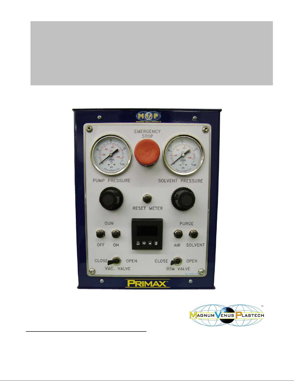
The CB-5000-PRX RTM Control Box is a modular system used to manually control the RTM
process. The CB-5000-PRX RTM Control Box includes a Digital Resin Meter. Using an optical
sensor, pulses are sent to the meter as the pump moves and then when a preset number
(amount of resin) is reached the gun & pump are turned off. It can be used with a basic
Primax pumping system or added to an existing RTM system. Then as the RTM process
demands more control, components can be added and manually controlled at the CB-5000PRX Control Box.
The CB-5000-PRX gives the option to control the following components:
Pump pressure
Solvent Flush pressure
Gun ON
Gun OFF
Solvent Purge / Flush
Air Purge / Flush
RTM Valve ON (injection port)
RTM Valve OFF (injection port)
Vacuum Assist Valve ON
Vacuum Assist Valve OFF
Digital Resin Meter (meters an
accurate amount of resin)
Page 5

5
2
CHAPTER
RTM Control Box Programming:
Quick Start
1. Turn power to the Control Box on
2. To set the Preset (number of counts) press or key once. Use the key to
increase that column to the desired number. Use the key to select the desired
column; you must set each of the columns, one’s, ten’s, and hundred’s separately.
3. When finished entering the desired number into the Preset press the key once to
store the number.
Note: Pressing the key will reset the counter to zero.
Calibration & Setup:
The Meter will take counts from a sensor assembly attached to the pump assembly. The
sensor assembly will send the meter a given number of counts per stroke depending on the
sensor assembly installed. The more counts per stroke provided to the meter the more
accurate it will be.
There are a couple of methods of calibrating the Preset for your part.
Set the counter at the maximum setting or very high for the first operation. Once you have
filled your part with the desired amount of material note the number on the display. This
number becomes your Preset. Enter the number into your Preset, when the counts reach that
number the pump will shut off and the display will reset to zero.
Another method to determine your Preset is to
1. Test sample resin by cycling the resin pump 10 full up and down strokes and note the
number that appears on the display.
2. Weigh the resin sample that was discharged from the pump.
3. Divide the desired amount (weight) of resin required to produce the part by the amount
(weight) of the resin sample discharged in the step above (step #2)
A (desired weight)
B (resin sample weight)
4. Multiply the number noted in step #1 by C the number derived in step #3. This becomes
your Preset, enter this number into your Preset, when the counts reach that number the
pump will shut off and the display will reset to zero.
= C
Page 6

6
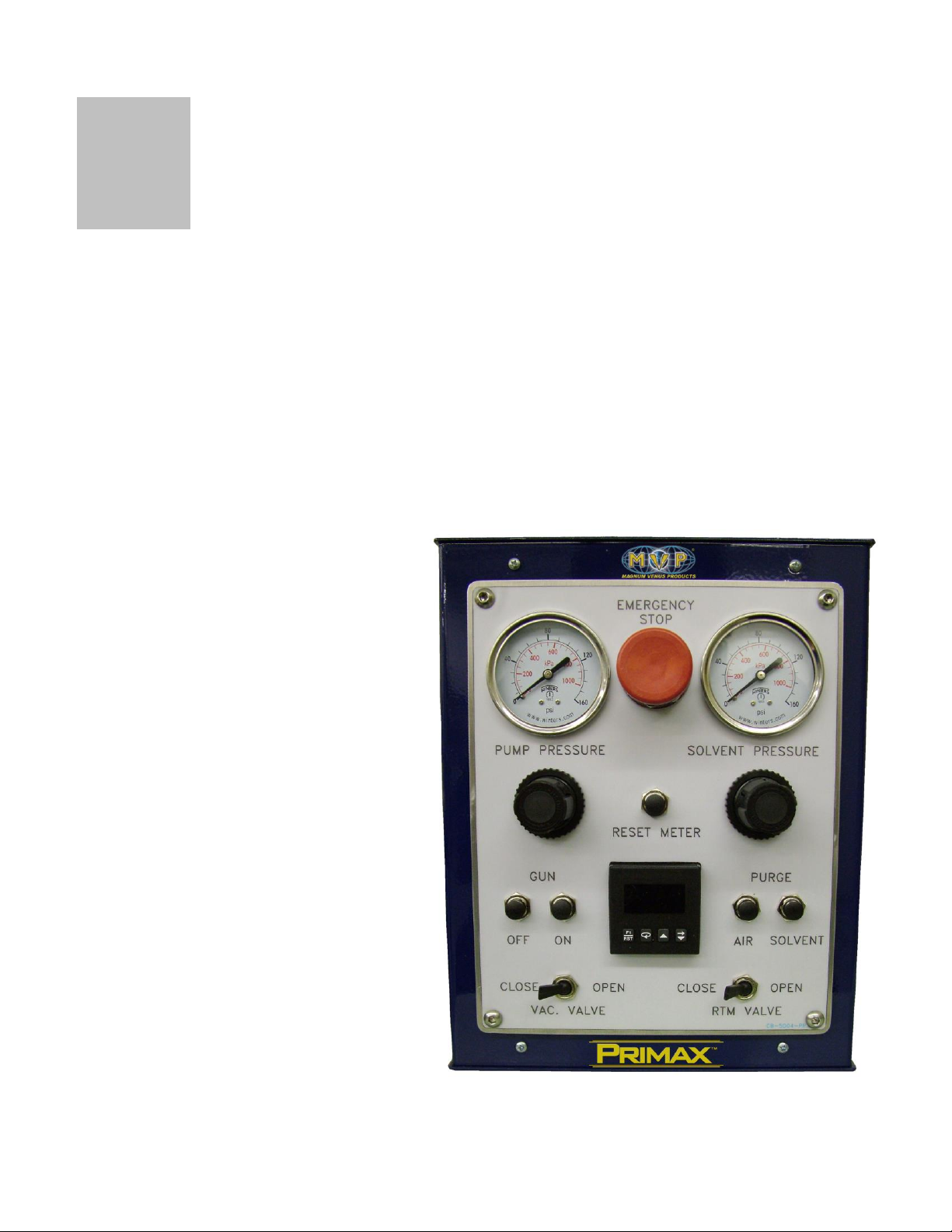
Front Panel Description:
The front panel bezel material is flame and scratch resistant, textured plastic with clear viewing
window that meets NEMA 4X/IP65 requirements, when properly installed. Continuous
exposure to direct sunlight might accelerate the aging process of the plastic material used in
the bezel. The bezel should be cleaned only with a soft cloth and neutral soap product. Do
NOT use solvents.
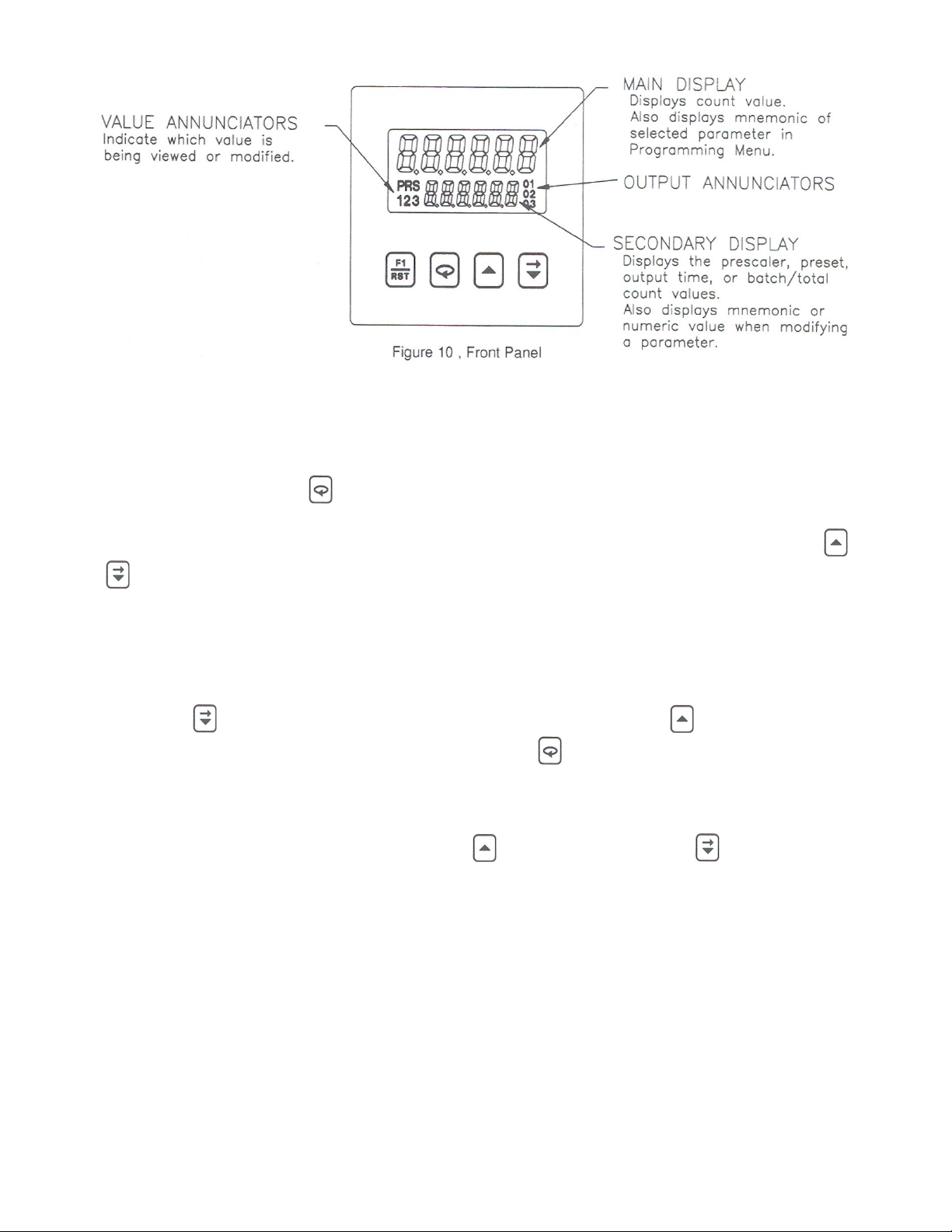
There are up to seven annunciators available in the lower display that illuminate to inform the
operator of the counter and output status. See Figure 10, Front Panel, for a description of the
annunciators.
Four front panel keys are used to access different modes and parameters. The following is a
description of each key.
Do not use tools of any kind (screwdrivers, pens, pencils, etc.) to operate the keypad of this
unit.
Keypad Functions:
This key is a user programmable key. When the key is pressed, the unit performs the
appropriate function as programmed. The RST printing on this key is used as a quick
reference for the operator if the function key is selected for a reset function.
This key is used to access programming, enter changes to data values, and scroll
through the available parameters in any mode.
This key selects the next available mode option during programming. When
programming a numerical value in digit entry mode, this key is used to increment the selected
digit position. When in auto scrolling entry mode, it increments the value. When in the
operating mode, this key is pressed to allow changing of the data value viewed in the
secondary display.
When programming a numerical value in digit entry mode, this key accesses the value
and selects the digit to the right. When in auto scrolling entry mode, it decrements the value.
When in the operating mode, this key is pressed to allow changing of the data value viewed in
the secondary display.
Page 7
7
Programming Numeric Data Values:
The presets, prescaler, and output time values may be accessible when the unit is in the
normal operating mode (not programming mode), providing that the Program Disable input is
not activated. Pressing the key will sequence the secondary display through the available
presets, prescaler, and output time values.
To change a numeric data value it must be visible on the secondary display. Pressing the
or key will allow changing of the value. The two methods for changing numeric data values
are "digit entry" and "auto scrolling".
Digit Entry:
If the data entry method has been set to "digit entry", the least significant digit will blink.
Pressing the key multiple times will select other digits. Pressing the will increment the
selected digit. The data value will be entered when the key is pushed, or the old value will
be retained if no key activity is detected for 10 seconds.
Short-Cut - Decrementing Value
To decrement a digit value, press and hold the key and then press the key. This will
decrement the selected digit to zero if held.
Page 8

8
3
SHIFT VALVE SUPPLY
SOLVENT TANK PRES.
VACUUM VALVE OFF
VACUUM VALVE ON
AIR PURGE
SOLVENT PURGE
RTM VALVE ON
RTM VALVE OFF
GUN ON
GUN OFF
CHAPTER
Making Control Box Connections:
To make the connections disassemble the connector plug attached to the side of the control
box. Use 1/4 inch poly tube, MVP number 01417 and Hose Clamp 7701-2-1 to make
connections between the connector plug and component. Connections are made by sliding
the Hose Clamp onto the correct poly tube pushing the poly tube onto the correct barb fitting
and thread the Hose Clamp over the poly tube and barb fitting. It is a good idea to mark both
ends of each piece of tubing to aid in trouble shooting and plumbing.
The CB-5000 is a modular system and for this manual it will show how to make all
connections. If the connection to the Vacuum valve, RTM valve or the Gun are not going to be
used you must plug the “OFF” signals. This can be done by attaching a short piece of poly
tube to correct port and folding it over (kink) then tape it to itself, or plugging it with something.
The “ON” signals or other components will only blow air if they are pushed, but can be plugged
as desired by following the process mentioned above.
Below is a diagram of the signal connections for the CB-5000-PRX RTM Control Box.
It is best to organize and plan the routing of the tubing as it is installed to make the installation
easier and look better. Use plastic ties or tape to pair similar tubing and control the tubing
bundle.
Page 9

9
Plug Disassembly:
1. Remove the four screws holding the outer shell of the plug together.
2. Remove the inner guard from the plug shell. Remember to put the tubing thru the inner
guard before connecting it to the barb fitting.
Shift Valve Supply:
3. Mark both ends of the poly tube appropriately and put one end thru the inner guard and
slide the hose clamp onto the tube and then attach it to the #1 barb fitting. (see diagram
above)
4. Push the other end of the poly tube into the push fitting located on the bottom side of
the air motor valve.
Solvent Tank Pressure:
5. Mark both ends of the poly tube appropriately and put one end thru the inner guard and
slide the hose clamp onto the tube and then attach it to the #2 barb fitting. (see diagram
above)
6. Attach the other end of the poly tube to the Flush Tank on the side marked as “AIR”.
Vacuum Assist Valve:
7. Mark both ends of the poly tube appropriately and put one end thru the inner guard and
slide the hose clamp onto the tube and then attach it to the #3 barb fitting (Vacuum
Valve “OFF” signal). (see diagram above)
8. Push the other end into the push fitting located at the top of the Vacuum Assist Valve.
(see drawing below)
9. Mark both ends of the poly tube appropriately and put one end thru the inner guard and
slide the hose clamp onto the tube and then attach it to the #4 barb fitting (Vacuum
Valve “ON” signal). (see diagram above)
10. Push the other end into the push fitting located on the bottom of the air cylinder of the
Vacuum Assist Valve, just below the “OFF” signal. (see drawing below)
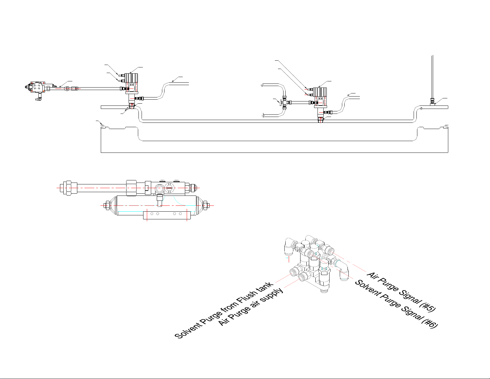
Air Purge:
11. Mark both ends of the poly tube appropriately and put one end thru the inner guard and
slide the hose clamp onto the tube and then attach it to the #5 barb fitting (Air Purge).
(see diagram above)
12. Push the other end into the push fitting located at the top of air purge portion of the RTM
Flush Valve mounted on the gun. (see drawing below)
Page 10

10
Solvent Purge:
13. Mark both ends of the poly tube appropriately and put one end thru the inner guard and
slide the hose clamp onto the tube and then attach it to the #6 barb fitting (Solvent
Purge). (see diagram above)
14. Push the other end into the push fitting located at the top of solvent purge portion of the
RTM Flush Valve mounted on the gun. (see drawing below)
RTM Valve / Injection Port:
15. Mark both ends of the poly tube appropriately and put one end thru the inner guard and
slide the hose clamp onto the tube and then attach it to the #7 barb fitting (RTM Valve
“ON”). (see diagram above)
16. Push the other end into the push fitting located on the bottom of the air cylinder of the
RTM Valve, just below the “OFF” signal. (see drawing below)
17. Mark both ends of the poly tube appropriately and put one end thru the inner guard and
slide the hose clamp onto the tube and then attach it to the #8 barb fitting (Vacuum
Valve “OFF”). (see diagram above)
18. Push the other end into the push fitting located at the top of the RTM Valve. (see
drawing below)
Gun Control:
19. Mark both ends of the poly tube appropriately and put one end thru the inner guard and
slide the hose clamp onto the tube and then attach it to the #9 barb fitting (Gun “ON”
signal). (see diagram above)
20. Attach the other end into the fitting located at the front of the Pro Gun. (see drawing
below)
21. Mark both ends of the poly tube appropriately and put one end thru the inner guard and
slide the hose clamp onto the tube and then attach it to the #10 barb fitting (Gun “OFF”
signal). (see diagram above)
22. Attach the other end into the fitting located at the back of the Pro Gun. (see drawing
below)
Page 11
11
VACCUM VALVE FLUSH ASSY.
AIR/FLUSH FOR VACUUM ASSIST VALVE
VACUUM ASSIST LINE
Inner/Part Seal
Outer Mold Seal
RTM-LT-CK
TO WASTE TANK/BUCKET
MAS-1000
Mold Half
MAS-1001
VACCUM VALVE - OFF SIGNAL (#3)
VACCUME VALVE - ON SIGNAL (#4)
Vacuum Clamp
RTM-3000
Auto Pro Gun
RTM VALVE - ON SIGNAL (#7)
RTM VALVE - OFF SIGNAL (#8)
MAS-1000
TO WASTE TANK / BUCKET
MAS-1001
Auto Pro Gun
Gun “ON” Signal (#9)
Gun “OFF” Signal (#10)
RTM Flush Assembly
Use caution to connect the correct signal
line to the corresponding purge material
Page 12

12
CONNECTOR PLUG & INNER
GUARD
PIN OUT/ PLUMBING DECAL
REGULATED AIR SUPPLY TO
AIR MOTOR
SENSOR (APS-1025) ATTACHES
TO CSD-1000-UPS and CSD-1000APS, LOCATED ON THE PUMP
BASE PLATE – USE SENSOR ESEN-102 FOR PATRIOT UNITS.
SENSOR CABLE (APS-1024)
USED WITH APS & UPS UNITS
MAIN AIR SUPPLY TO THE CB5000-PRX RTM CONTROL BOX
Miscellaneous Connections:
1. Screw the Sensor (APS-1025) in to the Sensor Mount (CSD-1005-M12) on the side of the
pump base plate (see drawing CSD-1000-UPS sensor assembly – UPS Drive in the
drawing section).
2. Connect the main air supply to the control box supply ball valve. The air supplied to the
control box should be clean and dry. (minimum 8 CFM @ 100psi)
3. Connect the regulated pump air supply to the air motor inlet.
4. Plug the power cord into an appropriate power supply. (110-220 volts AC)
Page 13

13
4
CHAPTER
Start up and Shut down procedures:
RTM LITE SYSTEM DAILY START UP:
1. Check all hoses for damage.
2. Check all material supplies and fill or replace as needed.
3. Open main inlet air valve on the air manifold.
4. Turn on power to the Control Box.
5. Open recirculation valve on Catalyst Manifold
6. Remove the Pivot Pin from the UPS catalyst pump drive.
7. Manually pump the catalyst pump with the UPS drive, observe catalyst returning to the
catalyst jug, pump until the stream is air free.
8. Check pump air regulator and gauge if needed use the regulator on the manifold, slowly
turn up the pump air pressure to the operating pressure, normally 25 – 40psi. If a safety
over ride valve is installed press and hold the priming button while adjusting air pressure.
Note: If the Pump pressure is too high the mold can be damaged. The pressure
compensating valve (PCV-2000) is recommended to help prevent excessive mold
pressures.
9. Close recirculation valve on Catalyst Manifold.
10. Manually pump the catalyst pump with the UPS drive, bring catalyst pressure to operating
pressure 100 – 200psi.
11. Replace the Pivot Pin into the UPS catalyst pump drive.
12. Adjust the catalyst percentage as required.
13. Set the Preset number / amount of material into the Resin Meter.
14. Reset counter in preparation for injection.
15. Insert the Distribution Ring into the Mix Chamber locating rim.
16. Place mix housing Seal into the Mix Chamber locating rim.
Page 14

14
17. Insert the Catalyst Injector and injector seal into the aperture in the Distribution Ring. The
spring goes into the gun block.
18. Place Mix Chamber and Catalyst Injector onto the front of the Pro Gun, secure it with the
2 screws.
19. Flush the assembled mix chamber with solvent.
20. Apply a little red grease (6706-2-1) to the threads of the mix chamber.
21. Install the RTM-LT-CK onto the mix chamber.
DAILY SHUT-DOWN:
1. Disconnect the gun from the injection port.
2. Flush the gun with solvent.
3. Remove RTM-LT-CK assembly from the mix chamber.
4. Turn off the main inlet air ball valve at the manifold.
5. Turn off power to the Control Box.
6. Release the solvent flush tank pressure, by lifting pressure relief valve.
7. Release Catalyst pressure by opening the recirculation valve on the catalyst manifold.
8. Remove the Mix Housing and clean it.
9. Wipe the gun block face with a clean rag.
10. Hang the gun with the gun block exit holes facing down.
Emergency Stop:
If the emergency stop button is pushed during operation the gun and pump will stop. To
restart pull out the emergency stop button and push the gun “ON” button.
It may take a split second for the pump to stop traveling and a count might be registered on
the counter. So beware you will want to monitor the amount of material injected into the mold
and correct for this situation. This condition could also occur if the gun is turned off during the
injection process.
Page 15

15
5
CHAPTER
TROUBLESHOOTING:
The majority of problems can be traced to improper connections or incorrect set-up parameters. Be sure all connections are clean and tight, that the
correct output board is fitted, and that the set-up parameters are correct. Also, be sure the DIP switch settings and the User Input Plug Jumper
position are correct for the particular application.
PROBLEMS POSSIBLE CAUSE REMEDIES
NO DISPLAY 1. Power off. 1. Verify power.
2. Loose connection or improperly wired. 2. Check connections and wiring.
3. Bezel assembly not fully seated into rear of unit. 3. Check installation.
Err 1 DISPLAYED AT 1. Data error in count values detected by processor. 1. Press key.
POWER UP 2. Check signal lines for possible noise sources.
Err 2 DISPLAYED AT 1. Data error in preset, prescaler, or output time values 1. Press key.
POWER UP detected by processor. a. Check presets, prescaler, and output time values.
2. Check signal lines for possible noise sources.
Err 3 DISPLAYED AT 1. Data error in programming parameters detected 1. Press key.
POWER UP by processor. a. Check all programming parameters.
2. Check signal lines for possible noise sources.
UNIT DOES NOT COUNT 1. No input signal. 1. Check sensor connections.
a. Verify power to sensor.
2. Type of input signal incorrectly selected. 2. Check DIP switch settings.
3. Count inhibited. 3. Disable count inhibit.
4. Prescaler value too small. 4. Check prescaler value.
Page 16

16
PROBLEMS POSSIBLE CAUSE REMEDIES
UNIT COUNTS 1. Input signal type incorrectly selected. 1. Check DIP switches. Set HI/LO FRQ. switch to LO for
INCORRECTLY count speed of less than 50 Hz.
2. Inputs improperly connected. 2. Check sensor input connections.
3. Electrical noise interference. 3. Check power source for noise.
a. Check signal wire routing.
4. Incorrect counting mode 4. Verify count input mode.
5. Prescaler incorrect. 5. Verify prescaler.
UNIT COUNTS WHILE 1. User input reset mode set for momentary reset. 1. Program User input to a maintained reset.
RESET IS ACTIVATED
OUTPUTS NOT WORKING 1. Output board not installed. 1. Install output board.
2. Improperly wired. 2. Check wiring.
3. Incorrect output board. 3. Check output board.
4. Defective output board. 4. Check or replace output board.
Page 17

17
6
CHAPTER
Component Drawings:
1. CB-5000-PRX RTM CONTROL BOX
2. RTMFLUSH RTM DUAL FLUSH ASSEMBLY
3. SPG-1000-A AUTOMATIC SUPER PRO GUN ASSEMBLY
4. CPC-1000-A AUTOMATIC CLASSIC PRO GUN
5. CPC-2000-A AUTOMATIC CLASSIC PRO GUN – FIT MIX CHAMBER
6. Electrical Diagram
7. CSD-1000-UPS SENSOR ASSEMBLY – UPS
8. CSD-1006 PUMP BASE PLATE MODIFICATION
9. CSD-1000-HV SENSOR ASSEMBLY – HV UPS
10. PNEUMATIC CIRCUT
Page 18

18
Page 19

19
Page 20

20
PARTS LIST
ITEM
PART NUMBER
QTY
DESCRIPTION
66 09169-1 5 3-WAY PNL MNT VALVE
65 F-BHCS-04C-08 4 Hex Socket Button Head Cap Screw
64 09613 1 CORD SET
63 BV-6F6F-LP 1 BALL VALVE
62 PF-ME-06 1 ELBOW
61 NOF-06 1 FILTER
60 PF-SE-04-BR 1 MALE ELBOW
59 F-HN-06C 4 HEX NUT
58 F-SW-06 4 LOCK WASHER
57 F-HB-06C-40 4 HEX CAP SCREW
56 COL-CLMP 2 COLUMN CLAMP
55 PF-HN-06-04 1 HEX NIPPLE
54 07645 10 TERMINAL PLUG - 1/4 TUBE
53 07640 1 MULTI-PLUG
52 07644 10 TERMINAL SOCKET - 1/4 TUBE
51 01659 2 CHECK VALVE
50 TRU-1021 2 SWIVEL ELBOW FITTNING
49 07225 1 MALE CONNECTOR
48 00446-1 1 .25 TEE
47 PF-HN-04 1 HEX NIPPLE
46 F-KN-440 2 KEP NUT
45 F-PH-440-10 2 PAN HEAD SCREW
44 07254 1 SOLINOID VALVE
43 09575 2 STRAIN RELIEF
42 7701-3-19 2 BULKHEAD FITTING
41 7701-6-3 4 10-32 BARBED FITTING
40 MPM-2585 2 MALE ELBOW
39 PF-AP-04 2 ALLEN PLUG
38 00416 1 BRANCH TEE
37 09852 2 4-WAY TOGGLE VALVE
36 07234 3 MALE POLY ELBOW
35 PF-RB-04-02 1 PIPE BUSHING
34 08804 2 ELBOW
33 08185 2 FITTING
32 F-PH-832-20 2 PAN HEAD SCREW
31 7701-6-7 15 BARB FITTING
30 F-FW-03 2
29 08807 10 SWIVEL TEE
28 09750 3 SHUTTLE VALVE
27 09187 2 4-WAY VALVE - DUAL PILOT
26 F-HN-832 4 HEX NUT
MAGNUM VENUS PLASTECH
PRX CONTROL BOX ASSY CB-5000-PRX
Page 21

21
PARTS LIST
ITEM
PART NUMBER
QTY
DESCRIPTION
25 INCL WITH VALVE 1 LOCK WASHER
24 INCL WITH VALVE 1 NUT
23 09524 1 PULSE VALVE
22 08801 27 1/16 barb to 10-32 connector
21 F-KN-832 4 KEP NUT
20 F-PH-832-06 2 PAN HEAD SCREW
19 09068 2 ANGEL MNT BRKT - MINI VALVE
18 CB-5003-PRX 1
17 07414 2 WATTS REGULATOR
16 F-HB-04C-08 4 1/4 HEX BOLT
15 CB-5003-PRX-11 2 MOUNTING BRACKET
14 9807-1-1 5 PILOT OPERATOR
13 9807-2-1 1 PRESSURE SWITCH
12 F-HN-632 4 NIPPLE
11 F-PH-632-06 6 PAN HEAD SCREW
10 F- STS-632-06 12 SELF TAPPING SCREW
9 07641 1 MULTI SOCKET
8 F-HN-04C 8 PLATED HEX NUT
7 9811-1-1 1 PRE SET COUNTER
6 07311 1 PUSH BUTTON
5 05804 2 PNL MNT GAUGE
4 CB-5002-PRX 1 CONTROL PANEL FACE
3 CB-5005-PRX 2 ANGLE BRACKET
2 CB-5001B-PRX 1 PRIMAX CONTROL BOX
1 CB-5001A-PRX 1 PRIMAX CONTORL BOX FRONT
MAGNUM VENUS PLASTECH
PRX CONTROL BOX ASSY CB-5000-PRX
Page 22

22
MAGNUM VENUS PRODUCTS
RTM DUAL FLUSH ASSEMBLY
REV. A = ITEM 9 WAS 7304-3-1 SEAL WASHER QTY 6, REMOVED ALL FROM DRAWING, NEW ITEM 9 REPLACES 2 ITEM 13 7/21/045 JEM
RTMFLUSH
TYPICAL FLUSH VALVE ASSY
SHOWN ABOVE 3 REQUIRED
FLUSH VALVE ASSY
FLUSH VALVE ASSY
7
10
8
19
6
20
2
7
21
1
12
7
16
3
5
23
18
4
22
22
17
13
11
9
15
7
15
14
8
8
8
10
Page 23

23
1
00973
3
GRIP RING
PARTS LIST
RTM DUAL FLUSH ASSEMBLY RTMFLUSH
PART NO.
ITEM
QTY
DESCRIPTION
2
O-B-010 3
O-RING
3
O-K-008 3
O-RING
4
O-A-007 3
O-RING
5
9203-2-3 3
SPRING
6
04356
3
SPRING
7
06867 4
ADJUSTABLE ELBOW
9
O-E-3-904 2
O-RING
10
08807 2
ADJUSTABLE TEE
11
7701-4-6
1
SCREW PLUG
12
09750 1
SHUTTLE VALVE
16
5104-25-1 3
FLUSH BUTTON
18
58681-1
3
BODY - FLUSH VALVE
19
58716-1 3
PUSH STEM
20
58717-1
3
BODY - AUTO FLUSH
21
58718-1 3
BACKUP RING
22
5104-23-1 3
SEAL BODY
23
MPM-2052-6"
2
1/4" x 6' POLY TUBE
8
06977 4
FITTING - 10-32 x 1/4 POLY
14
5104-22-1 2
FLUSH VALVE NECK
17
58677-3 1
FLUSH NECK - DUAL FLUSH
15
5104-26-1 3
FLUSH SEAL
13
5104-21-1 1
SPLIT SEAL
NOTE:
DO NOT EXCEED 90 psi ON SOVENT OR AIR PURGE PRESSURE
Page 24

24
MAGNUM VENUS PRODUCTS
SuperPro Automatic Gun Assembly
REV. -
SPG-1000-A
WITH 58681-1 (AUTO FLUSH VALVE BODY)
REPLACE 5104-24-1 (FLUSH VALVE BODY)
1
2
3
4
18
10
14
5
6
7
19
23
20
25
24
25
15
16
22
11
12
9
17
21
24
4 REQD
8
13
NOTE:
Page 25

25
24
00373
2
POLY NUT
OPTIONAL PARTS AND ASSEMBLIES
PART NO.
ITEM
DESCRIPTION
QTY
FIGURE 1-1
1
58757-1 1
MOUNTING PAD - PRO GUN
PARTS LIST
SuperPro Automatic Gun Assembly SPG-1000-A
PART NO.
ITEM
QTY
DESCRIPTION
2
5110-6-1 1
GASKET - 2 POSITION GUN
3
VFTC-4200 1
ACTUATOR ASSEMBLY
4
5104-00-01
1
GUN BLOCK ASSEMBLY
5
5107-27-3
1
STD TURBULENT MIXER
6
T-002552C 1 SPRAY NOZZLE .052 x 50
7
8704-4-1 1
NOZZLE CAP
8
58681-1
1
AUTO FLUSH VALVE BODY
9
58716-1
1
PUSH STEM
10
58717-1 1 MANUAL / AUTO FLUSH BODY
11
58718-1 1
BACK UP RING
12
00973
1
GRIP RING
13
01019
1
O-RING
14
04356 1
SPRING
15
7304-3-1
1
NYLON SEAL
16
7701-6-3 1
BARBED FITTING
17
7701-2-1 1
HOSE CLAMP
18
7202-4-8
1
LOCK WASHER
19
7101-1-4
1
HEX CAP SCREW
20
MPH-2534 1
MALE ELBOW POLY FITTING
25
00437
2
FERRULE
21
7701-6-14 1
STRAIGHT POLY FITTING
22
00667
1
COMPACT ELBOW
23
02806-2
4
SLOTTED PAN HEAD SCREW
M6707-1-1
1
MANUAL - SUPERPRO GUNS
Page 26

26
MAGNUM VENUS PRODUCTS
Auto Pro Gun Assembly
REV. - 03/07/06 BT2
CPC-1000-A
1
2
3
4
5
9
2 REQD
PART OF 2
PART OF 2
PART OF 2
7
8
6
Page 27

27
OPTIONAL PARTS AND ASSEMBLIES
PART NO.
ITEM
DESCRIPTION
QTY
1
58704-1 1
MOUNTING PAD - PRO GUN
PARTS LIST
Auto Pro Gun Assembly CPC-1000-A
PART NO.
ITEM
QTY
DESCRIPTION
6A
5107-27-2
1
CRITICAL TURBULENT MIXER
1.75
4-1/4
2-1/2
5006
VENUS
4x 1/4-20 UNC
(PARTIAL BOTTOM VIEW)
2.55
7-5/8
MOUNTING HOLES
NOTE: WEIGHT (AS SHOWN) = 835 GRAMS.
2
CPC-1200-A
1
ACTUATOR ASSEMBLY
3
5104-00-01-A 1
GUN BLOCK ASSEMBLY
5
F-HB-04C-08 1 HEX BOLT
4
F-SW-04 1
LOCK WASHER
7
T-002552C
1
SPRAY NOZZLE .052 X 50
8
8704-4-1 1
NOZZLE CAP
9
02806-2
2
PAN HEAD SCREW
3A
5104-00-03-A 1
ABRASIVE GUN BLOCK
6
5107-27-3 1
STD TURBULENT MIXER
Page 28

28
1
2
3
4
5
9
2 REQD
MAGNUM VENUS PRODUCTS
Auto Pro Gun Assembly (International)
REV. - 03/07/06 BT2
CPC-1000-A-INT
PART OF 2
PART OF 2
PART OF 2
7
8
6
Page 29

29
OPTIONAL PARTS AND ASSEMBLIES
PART NO.
ITEM
DESCRIPTION
QTY
1
58704-1 1
MOUNTING PAD - PRO GUN
PARTS LIST
Auto Pro Gun Assembly CPC-1000-A-INT
PART NO.
ITEM
QTY
DESCRIPTION
6A
5107-27-2 1
CRITICAL TURBULENT MIXER
1.75
4-1/4
2-1/2
5006
VENUS
4x 1/4-20 UNC
(PARTIAL BOTTOM VIEW)
2.55
7-5/8
MOUNTING HOLES
NOTE: WEIGHT (AS SHOWN) = 835 GRAMS.
2
CPC-1200-A 1
ACTUATOR ASSEMBLY
3
5104-00-01-A-INT 1
GUN BLOCK ASSEMBLY
5
F-HB-04C-08
1
HEX BOLT
4
F-SW-04 1
LOCK WASHER
7
T-002552C
1
SPRAY NOZZLE .052 X 50
8
8704-4-1 1
NOZZLE CAP
9
02806-2 2
PAN HEAD SCREW
3A
5104-00-03-A
1
ABRASIVE GUN BLOCK
6
5107-27-3 1
STD TURBULENT MIXER
Page 30

30
1
2
3
4
6
7
5
10
2 REQD
MAGNUM VENUS PRODUCTS
Auto Pro Gun Assembly
REV. - 03/07/06 BT2
CPC-2000-A
PART OF 2
PART OF 2
PART OF 2
8
9
Page 31

31
1
58704-1
1
MOUNTING PAD - PRO GUN
PARTS LIST
Auto Pro Gun Assembly CPC-2000-A
PART NO.
ITEM
QTY
DESCRIPTION
4-1/4
2-1/2
4x 1/4-20 UNC
(PARTIAL BOTTOM VIEW)
2.55
MOUNTING HOLES
2
CPC-1200-A 1 ACTUATOR ASSEMBLY
3
VFTC-4100-A 1
GUN BLOCK ASSEMBLY
5
F-HB-04C-08 1 HEX BOLT
4
F-SW-04
1
LOCK WASHER
8
VFIT-6025 1
FIT NOZZLE
9
8704-4-1
1
NOZZLE CAP
6
VPG-1003 1
STATIC MIXER
7
VPG-1002
1
DIFFUSER
8.69
1.75
10
02806-2 2
PAN HEAD SCREW
3A
VFTC-4100-F-A
1
ABRASIVE GUN BLOCK
QTY
OPTIONAL PARTS AND ASSEMBLIES
ITEM
PART NO. DESCRIPTION
Page 32

32
MAGNUM VENUS PRODUCTS
Auto Pro Gun Assembly
REV. - 03/07/06 BT2
CPC-2000-A-INT
PART OF 2
PART OF 2
PART OF 2
8
9
1
2
3
4
6
7
5
10
2 REQD
Page 33

33
1
58704-1
1
MOUNTING PAD - PRO GUN
PARTS LIST
Auto Pro Gun Assembly CPC-2000-A-INT
PART NO.
ITEM
QTY
DESCRIPTION
4-1/4
2-1/2
4x 1/4-20 UNC
(PARTIAL BOTTOM VIEW)
2.55
MOUNTING HOLES
2
CPC-1200-A 1
ACTUATOR ASSEMBLY
3
VFTC-4100-A-INT
1
GUN BLOCK ASSEMBLY
5
F-HB-04C-08
1
HEX BOLT
4
F-SW-04
1
LOCK WASHER
8
VFIT-6025 1
FIT NOZZLE
9
8704-4-1 1
NOZZLE CAP
6
VPG-1003
1
STATIC MIXER
7
VPG-1002 1
DIFFUSER
8.69
1.75
10
02806-2
2
PAN HEAD SCREW
3A
VFTC-4100-F-A-INT
1
ABRASIVE GUN BLOCK
QTY
OPTIONAL PARTS AND ASSEMBLIES
ITEM
PART NO. DESCRIPTION
Page 34

34
MAGNUM VENUS PRODUCTS
Automatic Pro Duo 1:1 Gun Assembly
REV. - 04/07/06 BT2
CPD-4000-A
1
2
3
4
5
6
2 REQD
PART OF 2
PART OF 2
7
8
PART OF 2
Page 35

35
1
58704-1 1
MOUNTING PAD - PRO GUN
PARTS LIST
Auto Pro Gun Assembly CPD-4000-A
PART NO.
ITEM
QTY
DESCRIPTION
1.75
4-1/4
2-1/2
4x 1/4-20 UNC
(PARTIAL BOTTOM VIEW)
2.55
MOUNTING HOLES
2
CPC-1200-A
1
ACTUATOR ASSEMBLY
3
DUO-4100-A
1
GUN BLOCK ASSEMBLY
5
F-HB-04C-08
1
HEX BOLT
4
F-SW-04
1
LOCK WASHER
6
02806-2 2
PAN HEAD SCREW
7.80
7
01443 2 FT.
2 - 1 FT. TUBE SECTIONS
8
06946 1
Y CONNECTOR
Page 36

36
MAGNUM VENUS PRODUCTS
30
32
11
5
6
7
8
9
12
23
10
9
8
7
6
5
23
AUTOMATIC PRO 1:1 GUN BLOCK
CPD-4100-A
28
37
19
2
35
34
3
4
2
33
20
36
31
1
1
40
10
NOTE:
FLUSH VALVE ASSEMBLY IS THE
SAME ON BOTH SIDES OF THE
REV - 03/23/06 BT2
20
1
GUN BLOCK.
43
29
17
44
22
42
45
46
47
24
27
25
14
18
15
41
25
26
24
21
27
13
39
24
38
Page 37

37
DESCRIPTIONPART NO.
ITEM
PARTS LIST
QTY
ASSEMBLY - 1:1 GUN BLOCK CPD-4100-A
SEAL
02441-1
1
2
2
F-CS-832-10-GR8
4
SOCKET HEAD CAP SCREW
3
03199 2 BALL
4
04319
2
SPRING
5
5104-3-1
2
SECONDARY SEAL
6
5104-4-1
2
RELIEF SPACER
7
5104-5-1 2
RESIN SEAL
8
5104-7-1 2
PACKING RING
9
5104-8-1 2 PACKING NUT
10
5104-9-1 2 RESIN FITTING
11
5104-10-1 1 CENTER SPACER
12
5104-11-1 1 ACTUATING STEM
13
5104-21-1
2
FLUSH VALVE SPLIT SEAL
14
5104-22-1
2
FLUSH VALVE NECK
15
5104-23-1 2
FLUSH SEAL BODY
17
5104-25-1
2
FLUSH VALVE BUTTON
18
5104-26-1
2
FLUSH VALVE SEAL
19
5107-27-3
1
TURBULENT MIXER
20
F-BHCS-04C-06
2
SCREW
21
O-E-007
2
O - RING *DO NOT GREASE THIS O-RING*
22
O-E-008 2
O - RING *DO NOT GREASE THIS O-RING*
23
O-E-3-904 2
O - RING
24
7304-3-1 4
NYLON SEAL
25
7701-2-1 4
HOSE CLAMP
26
27
7701-6-3 4 BARB FITTING
28
8704-4-1
1
NOZZLE CAP
29
9203-2-3 2
SPRING
30
58691-1 1
1:1 GUN BLOCK
31
58692-3 1
MIX HOUSING
32
58693-1 1
VALVE ROD
33
58694-1
2
FACE SEAL
35
58696-1
2
PLUG
FIGURE 1-1
ELBOW FITTINGTRU-1021
2
PLUG SEAL
58695-1
34
2
58752-4
FLOW RESTRICTOR
36
1
ASSY - MIX HOUSING
ASSY - FILLED RESIN SEAL
ASSY - FLUSH ELBOW
ASSY - FLUSH VALVE
OPTIONAL PARTS AND ASSEMBLIES
DESCRIPTION
58692-1
5104-29-01
5104-02-01
58742-1
PART NO.
40
15A
39
38
ITEM
1
1
2
2
QTY
36A
58752-2
1
2:1 FLOW RESTRICTOR
FT-652
37
1
SPRAY NOZZLE
58752-3
36B
1
3:1 FLOW RESTRICTOR
58752-4
36C
1
4:1 FLOW RESTRICTOR
58752-5
36D
1
5:1 FLOW RESTRICTOR
58752-6
36E
1
6:1 FLOW RESTRICTOR
58752-7
36F
1
7:1 FLOW RESTRICTOR
58752-8
36G
1
8:1 FLOW RESTRICTOR
9:1 FLOW RESTRICTOR
158752-9
36H
10:1 FLOW RESTRICTOR
1
58752-10
36J
1
58693-1 VALVE ROD MUST BE INSTALLED WITH THE SLOTTED END TO THE LEFT SIDE
OF GUN BLOCK WITH ACTUATING STEM DOWN AS SHOWN ON DWG.
47
58716-1
04356
O-B-010
58717-1
58718-1
00973
58681-1
43
46
44
45
41
42
PUSH STEM
SPRING
O-RING
MANUAL / AUTO FLUSH BODY
BACK UP RING
GRIP RING
FLUSH VALVE BODY
2
2
2
2
2
2
2
Page 38

38
ELECTRICAL DIAGRAM
Item Part No. Qty. Description
11 APS-1025 1 SENSOR
APS-1024 1 CABLE ASSEMBLY
14 07254 1 4-WAY VALVE
15 9807-1-1 1 OPERATOR
16 9807-2-1 1 SWITCH
18 9811-1-1 1 PRESET COUNTER
Page 39

39
Page 40

40
MAGNUM VENUS PRODUCTS
Hardware Kit - UPS Catalyst Sensor
REV. - 12/1/05 JEM
CSD-1000-UPS
2
3
7
8
8
8
9
6
1
10
12
4
5
11
3101-8 (REF)
PISTON ROD ADAPTER
Page 41

41
OPTIONAL PARTS AND ASSEMBLIES
PART NO.
ITEM
DESCRIPTION
QTY
1
02670-8 1
SHOULDER BOLT
PARTS LIST
Hardware Kit - UPS Catalyst Sensor CSD-1000-UPS
PART NO.
ITEM
QTY
DESCRIPTION
2
7102-15-16 1 SET SCREW
3
CSD-1002 1 MAGNET HOLDER
4
CSD-1003-UPS
1
CONNECTING ROD
5
CSD-1004-UPS 1
PIN - CAT SENSOR MNT
6
CSD-1005-M12 1
SENSOR MOUNT
7
CSD-1006
1
MODIFIED PUMP PLATE
8
CSD-1007 3
MAGNET
9
CSD-1008 1
ROD END
6A
CSD-1005-M8
1
SENSOR MOUNT
10
F-CS-04C-12
1
SOCKET HEAD CAP SCREW
11
F-HN-O4C 1
HEX NUT
11
F-HN-O4F 1
HEX NUT
Page 42

42
CSD-1006 SENSOR MOUNTING HOLE – PUMP BASE PLATE
PUMP BASE PLATE MODIFICATION
ADD SENSOR MOUNTING HOLE TO EXISTING SYSTEMS AS SHOWN ABOVE.
Page 43

43
MAGNUM VENUS PRODUCTS
Hardware Kit - HVLS Resin Sensor
CSD-1000-HV
2
3
7
8
8
9
6
1
10
12
4
5
11
VLS-4613 (REF)
PISTON ROD ADAPTER
REV. 09-18-07 BT2
8
Page 44

44
OPTIONAL PARTS AND ASSEMBLIES
PART NO.
ITEM
DESCRIPTION
QTY
1
02670-8 1
SHOULDER BOLT
PARTS LIST
Hardware Kit - HVLS Resin Sensor CSD-1000-HV
PART NO.
ITEM
QTY
DESCRIPTION
2
7102-15-16
1
SET SCREW
3
CSD-1002
1
ASSY - MAGNET HOLDER
4
CSD-1003-UPS 1
CONNECTING ROD
5
CSD-1004-UPS 1
PIN - CAT SENSOR MNT
6
CSD-1005-M12 1 SENSOR MOUNT
7
HVLS-1002-CSD 1
MODIFIED PUMP PLATE
8
CSD-1007
3
MAGNET
9
CSD-1008
1
ROD END
6A
CSD-1005-M8
1
SENSOR MOUNT
10
F-CS-04C-12
1
SOCKET HEAD CAP SCREW
11
F-HN-04C 1
HEX NUT
12
F-HN-04F 1
HEX NUT
Page 45

45
Page 46

46
MAGNUM VENUS PLASTECH
CORPORATE HEADQUARTERS and MANUFACTURING
5148 113th Ave. N. *Clearwater, FL 33760 * Tel 727-573-2955 * Fax 727-571-3636
TECHNOLOGY CENTER and MANUFACTURING
1862 Ives Ave. * Kent, WA 98032 * Tel 253-854-2660 * Fax 253-854-1666
MVP Plastech UK
Chilsworthy Beam, Gunnislake, Cornwall, PL18 9AT UK, * Tel:+44 (0) 1822 832621
Fax: +44 (0) 1822 833999
www.mvpind.com
 Loading...