

Page 1
MS-CEFB
Filter Box
Magnum Energy, Inc.
2211 West Casino Rd.
Everett, WA 98204
Phone: 425-353-8833
Fax: 425-353-8390
Web:
http://magnumenergy.com
Installation Guide
Page 2
Introduction
Introduction
The CE Filter Box (PN: MS-CEFB) is an EMI (electromagnetic interference)
fi lter designed to control conducted emissions on the AC and DC side of
Magnum Energy’s MS-E and MS-PE Series inverters. It is used to ensure that
stringent international standards for electromagnetic compatibility (EMC)
are met. For specifi c EU directives and standards see info on the back page.
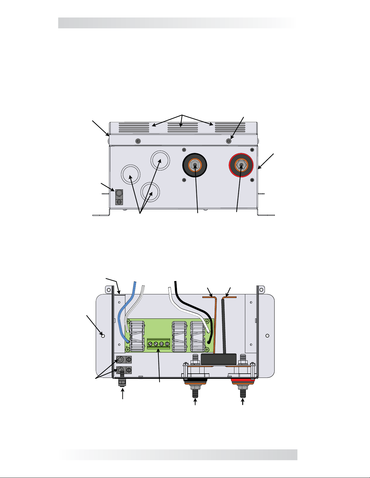
Refer to Figures 1 & 2 below to identify the MS-CEFB fi lter box’s features.
Top
Cover
DC
Ground
Connection
Inner Flange
Air Intake Vents
Dual knockouts (x3)
(1.9 and 2.5 cm)
Negative DC
Terminal
Cover screws (x4)
(#25 Torx)
Positive DC
Terminal
Figure 1, MS-CEFB Front Side Features
AC Output
Wires
AC Input
Wires
Negative DC
Busbar
Positive DC
Busbar
Filter
Base
Mounting
Holes (x2)
Toroid
AC
Ground
Connections
Ground
Connection
AC Input/Output
Terminal Block
DC
Negative DC
Terminal
Positive DC
Terminal
Figure 2, MS-CEFB Inside Features
1 © 2014 Magnum Energy, Inc.
Page 3
Introduction
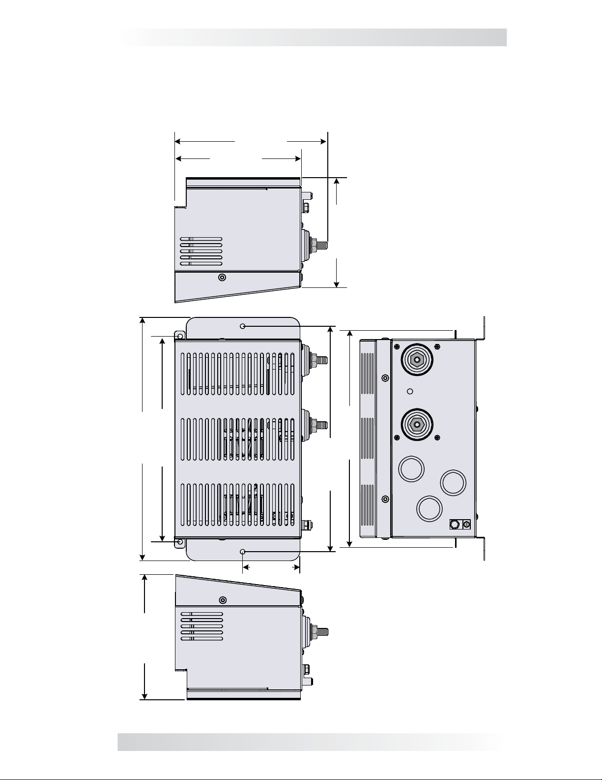
Knockouts and Dimensions
The MS-CEFB provides knockouts for use with ¾” and 1” trade size* conduit,
and adds just over 20 cm to the length of the inverter (see Figure 3).
* – “Trade size” refers to standard North American conduit. Actual openings
are approximately 2 cm and 2.7 cm.
20.3 cm
16.8 cm
14.5 cm
Right Side
Note: All four mounting
holes are approx. 6.4 mm (¼”)
Top
32.1 cm
16.5 cm
27.1 cm
28.7 cm
29.8 cm
7.6 cm
Left Side
Figure 3, MS-CEFB Dimensions
Front
© 2014 Magnum Energy, Inc. 2
Page 4
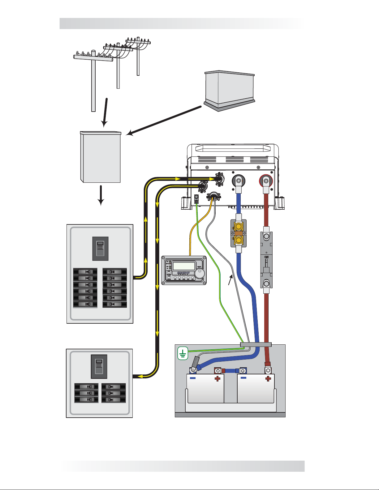
Installation
AC
RANSFER
T
S
WITCH
UTILITY POWER
(230VAC OUTPUT)
GENERATOR POWER
(230VAC OUTPUT)
MS-CEFB WITH
M
AGNUM INVERTER
230VAC POWER
TO INVERTER
ON
OFF
OFF
OFF
OFF
OFF
OFF
OFF
ON
ON
ON
ON
ON
ON
ON
ON
ON
ON
ON
ON
OFF
OFF
OFF
OFF
OFF
OFF
MAIN PANEL
230VAC PASS-THRU
POWER TO SUB-PANEL
ON
OFF
OFF
OFF
OFF
ON
ON
ON
ON
ON
ON
OFF
OFF
OFF
SUB-PANEL
ME-ARC
DC
HUNT
S
BTS
BATTERY BANK
DC
REAKER
B
Figure 4, Simplifi ed Installation Diagram
3 © 2014 Magnum Energy, Inc.
Page 5

Installation
Installation
CAUTION: Before installation, closely read and review all safety
information and procedures in this guide and in your inverter
owner’s manual.
WARNING: The inverter uses power from both AC and DC sources.
Before beginning the installation, ensure all AC power (utility/generator) and any negative/positive battery cables are safely disconnected from the inverter.
Review the simplifi ed system diagram shown in Figure 4 to assist you in
planning and designing your installation. This drawing is not intended to
override or restrict any national or local electrical codes. This drawing should
not be the determining factor as to whether the installation is compliant,
that is the responsibility of the electrician and the on-site inspector.
Safety Requirements
• The MS-CEFB should be reliably and permanently grounded (i.e., earthed)
to the system’s earth terminal. No plug or socket connection of the ground
wire is allowed.
• The EMI (electromagnetic interference) fi lter should be grounded before
connecting any power to the MS-CEFB. This bleeds relatively high leakage
currents through the fi lter common-mode capacitors to safety ground,
and removes hazardous voltage potentials from the fi lter body.
Installation Considerations
• In all installations, the inverter and the MS-CEFB should be installed
on the same metallic ground plane. Ensure all metal mating surfaces
used for connecting the inverter to the MS-CEFB are clean of paint, oil
or grease.
• It is recommended that equipment sensitive to EMI should be kept at
least 25 cm away.
• Any communication cable (remote, network, stacking and BTS) should
be separated from the AC IN and AC OUT power cables. Parallel runs of
cables should be avoided when possible. Cross-over of all cables should
be done at 90 degrees.
Unpacking and Inspection
Carefully remove the MS-CEFB fi lter box from the shipping container and
inspect all contents. Verify the following are included:
• MS-CEFB fi lter box
• Ferrite core
• DC terminal insulators (one black, one red)
• MS-CEFB Owner’s Manual
If items appear to be missing or damaged, contact your authorized Magnum
dealer or Magnum Energy. Save your proof-of-purchase as a record of ownership;
it will be needed if the unit should require in-warranty service.
Tools Needed
• #2 Phillips screwdriver • 1/2” wrench/socket
• 3/16” (≤4.8 mm) fl at-bladed screwdriver • 11/16” wrench/socket
• 7/16” wrench/socket
© 2014 Magnum Energy, Inc. 4
Page 6

Installation
MS-PE or MS-E inverter
Remove AC access cover
(#2 Phillips*)
Remove DC +/-
(1/2” Hex*)
Remove DC ground hardware
(7/16" Hex*)
Remove cover screws on each side
(#25 Torx*)
Stage I – Prepare Inverter
* Tool needed
to remove
terminal nuts
Stage II – Connect Filter Box to Inverter
Note: Before
re-attaching the
inverter’s DC
terminal nuts,
ensure the filter’s
DC busbars are
properly fitted over
the terminal bolts.
Stage III – Attach & Tighten Hardware
Figure 5, Attaching the MS-CEFB to the Inverter
5 © 2014 Magnum Energy, Inc.
Page 7

Installation
Installing the MS-CEFB
Prior to installation of the fi lter box, the inverter/charger must be prepared.
To prepare the inverter (Figure 5, Stage I):
1. Remove the inverter’s AC access cover (will need access to inside the
inverter to remove the DC ground connection and to wire AC connections).
2. Remove the inverter’s DC positive and negative terminal nuts/washers.
3. Remove the DC ground connection from the bottom left corner on the
front side of the inverter (reach into the AC terminal block compartment
to secure the hex nut while unscrewing the bolt on the outside of the
inverter using a 7/16” wrench/nut driver). Refer to Figure 6.
4. Remove the two #25 Torx screws that hold the inverter cover to the
base—located on each side of the inverter’s front.
To prepare the MS-CEFB fi lter box:
5. Detach the top cover of the fi lter box by removing the four #25 Torx
screws that secure the cover to the base.
6. Determine the AC and DC wiring through the fi lter box, and then remove
the appropriate knockouts (Figure 3).
Note: Magnum does not provide additional strain reliefs or conduit for
the knockout holes; to add either, you must supply the hardware.
To attach the MS-CEFB to the inverter (Figure 5, Stages II & III):
7. Attach the fi lter box to the inverter using the two #25 Torx screws that
were removed from the inverter cover in Step 4. Ensure the fi lter box’s
DC busbars align over the inverter’s positive and negative DC terminals.
8. Secure the fi lter box’s mounting fl anges—preferably to the same mount-
ing surface used for the inverter.
9. Re-attach the DC ground connection removed in Step 3—the ground’s
Hex screw fi ts through the inner fl ange on the fi lter box (Figure 6).
10. Re-attach and tighten the inverter’s DC positive and negative terminal
nuts/washers that were removed in Step 2—securing the fi lter box’s
DC busbars to their respective DC terminals on the inverter. Torque to
between 13.6 and 16.3 N-m (10 to 12 ft lbf).
¼-20 Hex nut*
Inverter
Int. tooth
¼”
lock washer (x2)
* Use 7/16"
wrench (or socket)
¼-20 x ¾
MS-CEFB
inner flange
Figure 6, Re-Attaching the DC Ground Hardware
© 2014 Magnum Energy, Inc. 6
Ground lug
Hex screw*
Page 8

Installation
To wire the inverter’s AC terminal block (top of Figure 7):
11. Route the fi lter box’s AC input/output wiring through the appropriate
knockouts/strain reliefs on the inverter, and then connect to the inverter’s
AC terminal block.
• Connect wire A (white w/ black stripe) to Terminal #1 (AC NEUT OUT).
• Connect wire B (blue) to Terminal #2 (AC HOT OUT).
• Connect wire C (black) to Terminal #3 (AC HOT IN).
• Connect wire D (white) to Terminal #4 (AC NEUT IN).
Tighten all to a maximum torque of 3.6 N-m (32 in lbf).
To wire the fi lter box’s AC terminal block (bottom of Figure 7):
12. Route the AC input source/output load wiring through the appropriate
knockouts/strain reliefs on the fi lter box, and then connect to the fi lter
box’s AC terminal block.
• Connect wire F (brown) to Terminal #1 (INV HOT OUT), and then
route and connect to the sub-panel.
• Connect wire G (blue) to Terminal #2 (INV NEUT OUT), and then
route and connect to the sub-panel.
• Connect wire H (blue) to Terminal #3 (INV NEUT IN), and then route
and connect to the main panel.
• Connect wire I (brown) to Terminal #4 (INV HOT IN), and then route
and connect to the main panel.
Tighten all to within a minimum/maximum torque of 1.2 N-m (10.6 in
lbf)/1.5 N-m (13.3 in lbf) – using a 3/16” (4.8 mm or less) fl at-bladed
screwdriver.
Note: The AC input source, output load, and grounds ( i.e., brown, blue,
and green with yellow stripe wires) are fi eld wires and must be provided
by the installer.
Info: Approved wire sizes for the MS-CEFB’s AC terminal block are
0.5-16 mm² (#20-6 AWG).
To wire the AC input/output grounds (bottom left of Figure 7):
13. Connect an AC ground wire from one of the fi lter box’s ground terminals
to the main panel’s ground busbar.
14. Connect another AC ground wire from the fi lter box’s other ground
terminal to the sub-panel’s ground busbar. Tighten both grounds to a
maximum torque of 5.1 N-m (45 in lbf).
Info: Approved wire sizes for the MS-CEFB’s ground terminals are
2 -33.6 mm² (#14-2 AWG) copper stranded.
To inspect the AC wiring:
1. Verify all wire runs are secured.
2. Verify strain reliefs or grommets are in place to prevent damage to the
wiring or conduit where it passes through walls or other openings.
3. Verify that all AC connections are correct, and all inverter and fi lter box
AC terminal screws are properly torqued.
4. Replace the inverter’s AC wiring access cover.
7 © 2014 Magnum Energy, Inc.
Page 9

Installation
AC NEUT OUT
(to Sub-Panel)
AC HOT OUT
(to Sub-Panel)
A
1 2 3
B
C
D
4
(from Main Panel)
AC HOT IN
(from Main Panel)
AC Terminal Block
(AC input/output wiring)
Note: AC GROUND
not needed
AC NEUT IN
MS-E
or
MS-PE Series
Inverter/Charger
MS-CEFB
B
AC GROUNDS
in/out
A
E
C
(from Main Panel)
(from Main Panel)
(to Sub-Panel)
INV NEUT OUT
(to Sub-Panel)
INV HOT OUT
1
F
Figure 7, AC Wiring
INV NEUT IN
2
3
4
H
G I
INV HOT IN
D
© 2014 Magnum Energy, Inc. 8
Page 10

Installation
To wire the MS-CEFB fi lter box to the battery bank:
1. Route the end of the positive DC battery cable from the battery bank
through the supplied red DC terminal insulator (do the same for the negative DC cable – using the black DC terminal insulator). The insulators protect the MS-CEFB’s DC terminals and can help prevent accidental shorts.
WARNING: Before connecting the DC cables from the battery bank
to the MS-CEFB, ensure DC overcurrent protection has been installed
and the correct DC voltage and polarity have been verified.
2. Connect the positive and negative battery cables to their respective terminal posts on the front of the fi lter box. When connecting the battery cables
to the fi lter’s DC terminals, the cable’s ring lug should be placed directly
against the fi lter terminal (Figure 8). Torque to 20.4 N-m (15 ft lbf).
3. Fit the red and black DC terminal insulators (that were routed over the
DC battery cables in Step 1) over their respective terminal posts.
WARNING: DO NOT close the DC circuit breaker or connect the fuse
to bring battery power to the inverter at this time. This will occur
in the Functional Test after the installation is complete.
Info: Refer to your inverter owner’s manual for the required DC
wiring sizes and overcurrent protection.
3/8"-16
SS Hex
Jam nut*
MS-CEFB DC terminal
(3/8"-16 bolt,
22 mm usable length)
3/8"
SS Flat
Battery cable
(with ring lug)
washer
3/8"
SS Spring
washer
CAUTION: Ensure nothing
is placed between the DC
terminal and ring lug.
Figure 8, MS-CEFB DC Hardware Installation
Communication Cables
When connecting a communication cable (remote, network, stacking or BTS)
to the inverter, a ferrite core must be connected to one end of the cable. A
ferrite core is shaped like a metal doughnut and is a passive electronic component used to suppress high frequency noise in electronic circuits. It is used
to reduce EMI that may be transmitting, and prevents the cable from acting
as an antenna and receiving interference from other devices.
Info: The BTS cable and another communication cable (e.g., remote
cable) can both fi t and be separately wrapped three times into a sin-
gle ferrite core. However, if using more than one cable with a single
ferrite, all must go in the same direction around the core.
* Use a 11/16" wrench
or socket
9 © 2014 Magnum Energy, Inc.
Page 11

Installation
To attach the ferrite core to a communication cable (Figure 9):
1. For each communication cable, route one end through the ferrite core
and wrap it several times around/through the core. There needs to be
at least three full turns around the ferrite core.
2. While wrapping the cable around the core, ensure the core is located as
close as possible to one end of the cable [within 2.5 to 5 cm (1-2 inches)
from the end]. The result should look something like Figure 9 below.
Note: Once the core is attached to the cable, plug the core-connected end of
the cable into the appropriate RJ11 port (Stack/Accessories, Remote, Network,
or BTS) on the inverter.
Communications
Cable
Note: Multiple cables can be wrapped
around a single ferrite core, but each
should have three full turns – ensure
each goes in same direction around core.
Ferrite
Core
Note: This end to be
connected to inverter port.
Figure 9, Ferrite Core Attached to a Communication Cable
Final Inspection
After all electrical connections to the inverter, batteries, AC source, and
sub-panel have been completed, follow the steps for the Functional Test as
directed in your inverter owner’s manual.
Note: When verifying the correct DC voltage, check the fi lter box’s positive
and negative DC terminals with a multimeter. When verifying the correct AC
output voltage, check the fi lter box’s AC terminal block NEUT OUT, HOT OUT,
and GROUND poles with a voltmeter (Figure 10 below).
Once your system passes all the steps, attach and secure the fi lter box’s cover.
AC Output
230 VAC
(± 5%)
Brown
Blue
Neutral to Ground
< 0.5 VAC
Figure 10, AC Voltage Checks
© 2014 Magnum Energy, Inc. 10
Page 12

EU Standards/Limited Warranty
EU Directives and Standards
A MS-CEFB (CE Filter Box) connected to a MS-E or MS-PE Series inverter/
charger conforms to the provisions of EMC Directive 1999/5/EEC, per:
• EN 55014-1 (2006) +A1, +A2, (> 1000W) Electromagnetic compat-
ibility – Requirements for household appliances, electric tools and similar
apparatus — Part 1: Emission
• EN 55014-2 (1997) +A1, +A2, Electromagnetic compatibility – Re-
quirements for household appliances, electric tools and similar apparatus
— Part 2: Immunity – Product family standard
• EN 61000-3-2 (2006) +A1, +A2, Electromagnetic compatibility (EMC)
— Part 3-2: Limits – Limits for harmonic current emissions (equipment
input current ≤16 amps per phase)
Additionally, these products conform to the C-Tick Mark requirements based
on the provisions in standard AS/NZS CISPR 14-1:2005.
Limited Warranty
Magnum Energy, Inc. warrants the CE Filter box for a maximum of 12 months
from the product’s original date of purchase according to the following terms
and conditions:
1. The limited warranty extends to the original purchaser of the product and
is not assignable or transferable to any subsequent purchaser.
2. During the limited warranty period, Magnum Energy will repair or replace
at Magnum Energy’s option any defective parts, or any parts that will not
properly operate for their intended use with factory new or remanufactured replacement items—if such repair or replacement is needed because
of product malfunction or failure during normal usage. The limited warranty does not cover defects in cosmetic appearance, or any decorative,
structural, or non-operative parts. Magnum Energy’s limit of liability
under the warranty shall be the actual cash value of the product at the
time the original purchaser returns the product for repair—determined
by the price paid by the original purchaser. Magnum Energy shall not be
liable for any other losses or damages.
3. Upon request from Magnum Energy, the original purchaser must prove
the product’s original date of purchase by providing a dated bill of sale
or itemized receipt.
4. This limited warranty is voided if:
• the product has been modifi ed without authorization;
• the product has been damaged through abuse, neglect, accident, or
corrosion;
• the product was not installed according to this installation guide.
11
PN: 64-0066 Rev A
 Loading...