

Page 1
MPX Series Extension Kit
Owner’s Manual
Page 2

Disclaimer of Liability
The use of this manual and the conditions or methods of installation, operation, use, and maintenance
of the MPX Extension Kit is beyond the control of Magnum Energy, Inc. Therefore, this company
does not assume responsibility and expressly disclaims liability for loss, damage or expense,
whether direct, indirect, consequential or incidental, arising out of or in anyway connected with
such installation, operation, use, or maintenance.
Due to continuous improvements and product updates, the images shown in this manual may not
exactly match the unit purchased.
Restrictions on Use
The MPX Extension Kit may only be used in life-support devices or systems with the express written
approval of Magnum Energy. F ailure of the MPX can reasonably be expected to cause failure of that
life-support device or system, or to affect the safety or effectiveness of that device or system. If the
MPX fails, it is reasonable to assume the health of the user or other persons may be endangered.
Copyright Notice
Copyright © 2011 by Magnum Energy, Inc. All rights reserved. Permission to copy, distribute, and/
or modify this document is prohibited unless express written permission from Magnum Energy , Inc.
is provided.
Contact Information
Magnum Energy, Inc.
2211 West Casino Rd.
Everett, WA 98204
Phone: 425-353-8833
Fax: 425-353-8390
Web: www.magnumenergy.com
Statement of Appreciation
From all of us at Magnum Energy Thank you for purchasing this Magnum Extension Kit (MPX).
We understand that you have many purchasing options in the marketplace, and are pleased that
you have decided on a Magnum Energy product. This MPX was proudly assembled and tested in the
United States at our Everett, Washington facility.
At Magnum, we are committed to providing you with quality products and services; and hope that
your experience with us is pleasant and professional.
Magnum Energy® is a registered trademark of Magnum Energy, Inc.
ii 2011 Magnum Energy, Inc.
Page 3

Table of Contents
1.0 Safety Information ........................................................................... 1
1.1 Safety Symbols .........................................................................................1
1.2 General Safety ..........................................................................................1
1.3 Battery Safety ...........................................................................................2
2.0 Introduction ..................................................................................... 3
2.1 MPX Series Kit...........................................................................................3
2.2 Available MPX Models .................................................................................5
3.0 Installation ....................................................................................... 7
3.1 Installing the MPX ......................................................................................7
3.1.1 Preparation .......................................................................................7
3.1.2 Attaching the MPX to the MP Enclosure ................................................10
3.1.3 Mounting the MP Enclosure (and Attached MPX) to a Backplate/Wall ........10
3.1.4 Attaching the DC and AC Breakers ...................................................... 11
3.1.5 Connect and Separate Inverter AC Wires ............................................. 13
3.1.6 Mounting the Second Inverter onto the MPX ........................................... 13
3.1.7 Attaching the Inverter Hood ...............................................................14
3.1.8 Attaching the Router Bracket .............................................................16
3.1.9 Attaching the Router to the Bracket ....................................................16
3.2 Wiring the MPX .......................................................................................17
3.2.1 Wiring Guidelines .............................................................................17
3.2.2 Wiring the MPXS-30D .......................................................................20
3.2.3 Wiring the MPXS-60S ........................................................................33
3.2.4 Wiring the MPXD-30D .......................................................................43
3.3 Installation Checklist ................................................................................52
3.4 Functional Test ........................................................................................52
3.5 Attaching Labels and Covers .....................................................................52
4.0 Warranty and Service ..................................................................... 58
4.1 Limited Warranty .....................................................................................58
4.2 How to Receive Repair Service...................................................................58
List of Tables
Table 2-1, MPX AC Wire Kit Part Numbers ...............................................................4
Table 2-2, DC 2/0 Battery Cable Lengths ................................................................5
Table 2-3, MPX Models .........................................................................................5
Table 3-1, MPX Wiring Table ................................................................................17
List of Figures
Figure 2-1, MPX Series Kit ....................................................................................3
Figure 2-2, MPX Kit Labels and Hardware ................................................................4
Figure 2-3, MPXS-60S Installation Confi gurations .....................................................5
Figure 2-4, MPXS-30D Installation Confi gurations ....................................................6
Figure 2-5, MPXD-30D Model Installation Confi guration ............................................6
Figure 3-1, MPX Series Dimensions and Knockout Locations/Sizes ..............................8
Figure 3-2, Removing a Knockout ..........................................................................9
© 2011 Magnum Energy, Inc. iii
Page 4

List of Figures (cont.)
Figure 3-3, Removing MPX Knockouts ....................................................................9
Figure 3-4, MPX with RTR Bracket .........................................................................9
Figure 3-5, Attaching the MPX to an MP Enclosure ................................................. 10
Figure 3-6, Mounting the MPX to a Backplate/Wall.................................................10
Figure 3-7, Removing Breaker Screws ................................................................. 11
Figure 3-8, Attaching the New DC Breaker ........................................................... 11
Figure 3-9, Attaching the New AC Breaker Within a MP Single Enclosure .................. 12
Figure 3-10, Attaching the New AC Breaker Within a MP Dual Enclosure ................... 12
Figure 3-11, Mounting the Second Inverter on the MPX.......................................... 13
Figure 3-12, Mounting Multiple Inverters on the MPX ............................................. 14
Figure 3-13, Attaching the Inverter Hood ............................................................. 15
Figure 3-14, Attaching Multiple Inverter Hoods ..................................................... 15
Figure 3-15, Attaching the Router Bracket ............................................................ 16
Figure 3-16, Mounting the Router to the Bracket ................................................... 16
Figure 3-17, DC Cable Connections ..................................................................... 19
Figure 3-18a, MPXS-30D / MPSL-30D Inverter AC Wiring ....................................... 23
Figure 3-18b, MPXS-30D / MPSL-30D External AC Wiring ....................................... 24
Figure 3-18c, MPXS-30D / MPSL-30D Inverter DC Wiring ....................................... 25
Figure 3-18d, MPXS-30D / MPSL-30D Battery Bank DC Wiring ................................ 26
Figure 3-18e, MPXS-30D / MPSL-30D Communication Wiring .................................. 27
Figure 3-19a, MPXS-30D / MPSH-30D Inverter AC Wiring ....................................... 28
Figure 3-19b, MPXS-30D / MPSH-30D External AC Wiring ...................................... 29
Figure 3-19c, MPXS-30D / MPSH-30D Inverter DC Wiring ....................................... 30
Figure 3-19d, MPXS-30D / MPSH-30D Battery Bank DC Wiring ............................... 31
Figure 3-19e, MPXS-30D / MPSH-30D Communication Wiring ................................. 32
Figure 3-20a, Inverter AC Input and Output Wiring Diagram .................................. 34
Figure 3-20b, MPXS-60S / MPSL-60S AC Breaker Input Wire Transition .................... 35
Figure 3-21a, MPXS-60S / MPSL-60S Inverter AC Wiring ........................................ 38
Figure 3-21b, MPXS-60S / MPSL-60S External AC Wiring ........................................ 39
Figure 3-21c, MPXS-60S / MPSL-60S Inverter DC Wiring ........................................ 40
Figure 3-21d, MPXS-60S / MPSL-60S Battery Bank DC Wiring ................................. 41
Figure 3-21e, MPXS-60S / MPSL-60S Communication Wiring .................................. 42
Figure 3-22a.1, MPXD-30D / MPDH-30D Inverter AC Wiring ................................... 46
Figure 3-22a.2, MPXD-30D / MPDH-30D Inverter AC Wiring (Closeup) ..................... 47
Figure 3-22b, MPXD-30D / MPDH-30D External AC Wiring ...................................... 48
Figure 3-22c, MPXD-30D / MPDH-30D Inverter DC Wiring ...................................... 49
Figure 3-22d, MPXD-30D / MPDH-30D Battery Bank DC Wiring ............................... 50
Figure 3-22e, MPXD-30D / MPDH-30D Communication Wiring ................................. 51
Figure 3-23, Attaching the Interior DC Labels ....................................................... 52
Figure 3-24, Attaching the MP Enclosure Cover ..................................................... 53
Figure 3-25, Attaching the MPX Cover ................................................................. 54
Figure 3-26, Attaching the Router Cover .............................................................. 55
Figure 3-27, Attaching the Exterior Labels MPSL/MPSH .......................................... 56
Figure 3-28, Attaching the Exterior Labels MPDH .................................................. 57
iv 2011 Magnum Energy, Inc.
Page 5
1.0 Safety Information
1.0 Safety Information
IMPORTANT SAFETY INSTRUCTIONS
This manual contains important safety instructions that must be followed during the installation and
operation of this product. Before using the MPX, read all instructions and cautionary markings in
this manual for: the MPX extension, the inverter/charger, the MP enclosure, and the batteries – as
well as the individual manuals provided for each component of the system.
These installation instructions are for use by qualifi ed personnel only. Do not perform any installation
or servicing other than that specifi ed in this owner’s manual unless you are qualifi ed to do so. Incor-
rect installation or servicing may result in a risk of electric shock, fi re, or other safety hazard.
1.1 Safety Symbols
The following safety symbols have been placed throughout this manual to indicate dangerous
conditions and important safety instructions.
WARNING: This symbol indicates that failure to take a specifi ed action could result in
physical harm to the user.
CAUTION: This symbol indicates that failure to take a specifi ed action could result in
damage to the equipment.
Info: This symbol indicates information that emphasizes or supplements important points
of the main text.
1.2 General Safety
• All electrical work must be performed in accordance with local and national electrical codes.
• This product is designed for indoor/compartment installation. It must not be exposed to rain,
snow, moisture, or liquids of any type.
• Use insulated tools to reduce the chance of electrical shock or accidental short circuits.
• Remove all jewelry such as rings, watches, bracelets, etc., when installing or performing
maintenance on the inverter.
• Both AC and DC overcurrent protection must be provided as part of the installation.
• Use Class 1 wiring methods for fi eld wiring connections to terminals of a Class 2 circuit.
• Listed or labeled equipment shall be installed and used in accordance with any instructions
included in the listing or labeling.
• To reduce risk of electric shock, disconnect all wiring before attempting any maintenance or
cleaning. Turning off the inverter will not reduce this risk, the inverter bypass must be used or
the panel should be totally disconnected from all sources.
• All wiring must have a minimum rating of 150V, 75°C when using 120V AC inverters; or 300V,
75°C when using 120V/240V AC inverters.
• AC wiring must be no less than 10 AWG (5.3 mm2) gauge copper wire.
• Battery cables should be no less than #4/0 AWG unless fused close to the battery bank for
smaller sized cables.
• Crimped and sealed copper ring terminal lugs with a 3/8” hole should be used to connect to the
DC terminals inside the MP enclosure. Soldered cable lugs are also acceptable.
• Torque all AC wiring connections and DC cable connections to the required torque values.
READ AND SAVE THESE INSTRUCTIONS
© 2011 Magnum Energy, Inc.
1
Page 6

1.0 Safety Information
1.3 Battery Safety
IMPORTANT BATTERY SAFETY INSTRUCTIONS
• Be very careful when working around batteries, they can produce extremely high currents if
short-circuited. Read the battery supplier’s precautions before installing and connecting the
inverter and batteries.
• Wear eye protection such as safety glasses when working with batteries.
• Remove all jewelry such as rings, watches, bracelets, etc., when installing or performing
maintenance on the batteries.
• Never work alone. Always have someone near you when working around batteries.
• Use proper lifting techniques when working with batteries.
• Never use old or untested batteries. Check each battery’s label for age, type, and date code to
ensure all batteries are identical.
• Batteries are sensitive to changes in temperature. Always install batteries in a stable environment.
• Install batteries in a well ventilated area. Batteries can produce explosive gasses. For
compartment or enclosure installations, always vent batteries to the outside.
• Provide at least one inch of air space between batteries to provide optimum cooling.
• Never smoke when in the vicinity of batteries.
• To prevent a spark at the battery and reduce the chance of explosion, alwa ys connect the cables
to the batteries fi rst. Then connect the cables to the MP enclosure/inverter system.
• Use insulated tools at all times.
• Always verify proper polarity and voltage before connecting the batteries to the MP enclosure/
inverter system.
• To reduce the chance of fi re or explosion, do not short across the battery terminal.
• In the event of accidental exposure to battery acid, wash thoroughly with soap and water . In the
event of exposure to the eyes, fl ood them for at least 15 minutes with running water and seek
immediate medical attention.
• Recycle old batteries.
• Be extra cautious to reduce the risk of dropping a metal tool onto batteries. It could short-circuit
the batteries or other electrical parts, resulting in sparks that could cause an explosion.
• Cover the terminals to prevent accidental shorting.
READ AND SAVE THESE INSTRUCTIONS
2
© 2011 Magnum Energy, Inc.
Page 7
2.0 Introduction
C
E
G
H
F
I
J
K
D
A
B
2.0 Introduction
The MPX Series Extension Kit provides the necessary equipment to mount and connect an additional
Magnum inverter to a MP Series enclosure and panel. The MPX is designed to allow a Magnum inverter to fi t seamlessly into the top.
IMPORTANT: If you have not yet installed any of your system (i.e., MP enclosure, fi rst
inverter), refer to the MP Owner’s Manual (PN: 64-0028) for initial setup instructions.
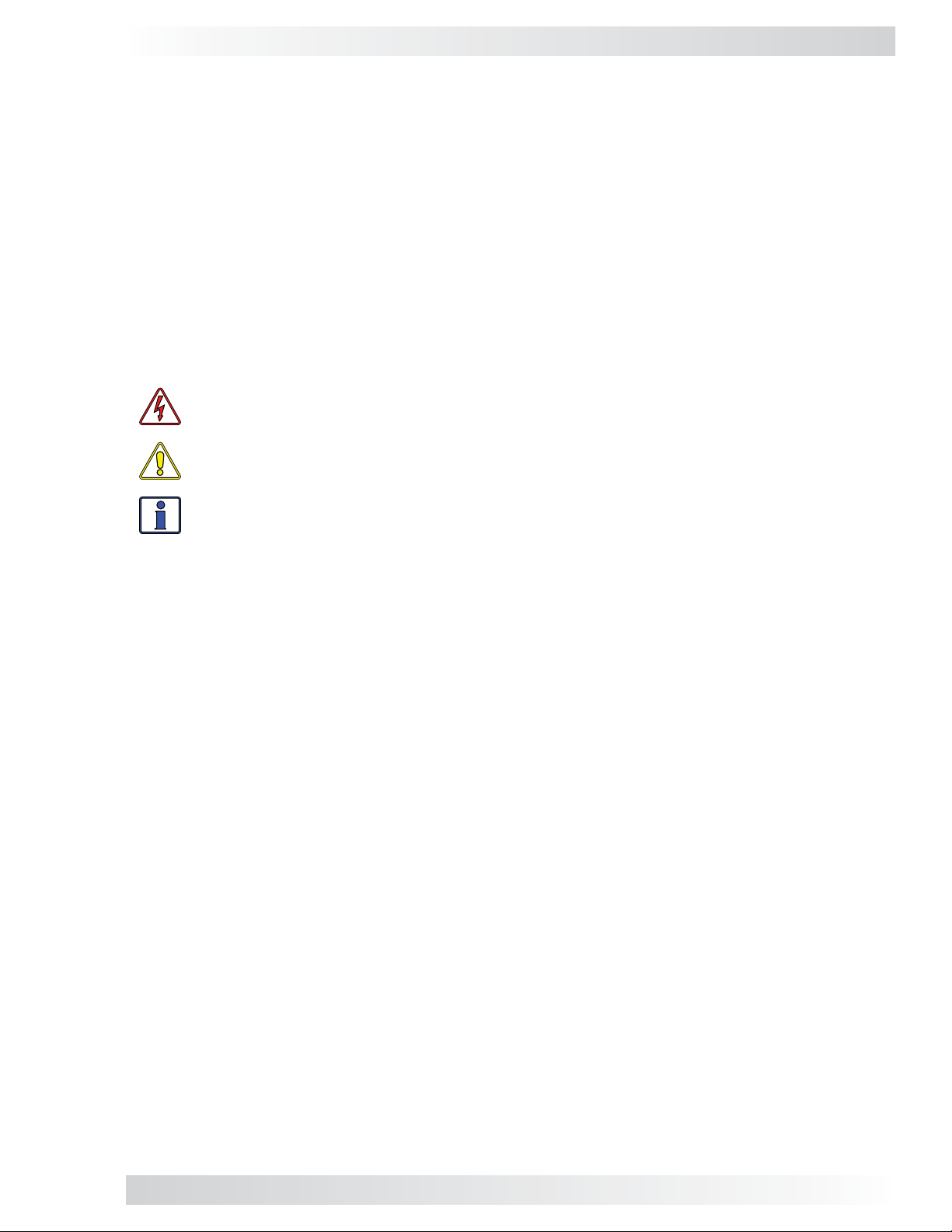
2.1 MPX Series Kit
Carefully remove the MPX from its shipping container and inspect all contents. Verify the below items
are included. Contact your authorized Magnum Energy dealer or Magnum Energy if anything is missing. Save your proof-of-purchase as a record of your ownership (needed for in-warranty service).
The MPX kit includes (see Figure 2-1):
A
MPX extension box
Inverter hood - for vertically mounting an
B
inverter
C
DC disconnect breaker - 250 ADC See Note* on stacking cables below.
Remote cable (300V) - for installing remote
G
control or router
Stacking cable - for series stacking MS4024
H
inverters or parallel stacking MS-PAE inverters
AC breaker - 30 AAC double-pole
D
(60 AAC single-pole with MPXS-60S)
DC positive/negative 2/0 AWG battery
E
cables (see Table 2-1)
MPX AC Wiring Kit - for wiring to the AC
F
terminals in MP panels (see Table 2-1)
Note* - The supplied parallel stacking cables must be used when installing the router. They are
like standard CAT 5 cables, but are rated for 300V to allow their use with the MS-PAE inverters and
to meet electrical safety code requirements.
I
Labels and mounting hardware (Figure 2-2)
J
MPX Series Owner’s Manual
Series Stacking Manual (MPXS-60S models
K
only)
© 2011 Magnum Energy, Inc.
Figure 2-1, MPX Series Kit
3
Page 8
2.0 Introduction
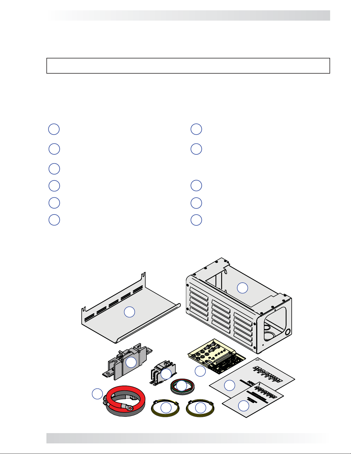
1
- (x4) ⅜”-16 x ¾” Hex bolts
4
2
- (x4) ⅜” split washers
1
2
3
TOP CONNECTION
OF
DC BREAKER
DC
POS
DC POS Top
Connection
MASTER
INVERTER
MASTER
INVERTER
MASTER
INVERTER
MASTER
INVERTER
TO
IN V
7
5
6
BOTTOM CONNECTION
OF
DC BREAKER
DC
POS
DC POS Bottom
Connection
SLAVE 1
INVERTER
SLAVE 1
INVERTER
SLAVE 1
INVERTER
SLAVE 1
INVERTER
8
TO
BAT
- (x2) ⅜”-16 nuts
3
4
- (x4) #8-32 x ¼” (T20) Torx screws
5
- (x1) #10-32 x ⅜” (T25) Torx screw
6
- (x1) #10 lock washer
7
- (x2) #10-32 x 3½” (T25) Torx screws
8
- (x2) DC breaker mounting straps
INVERTER
AC INPUT
SWITCH ON
TO CHARGE /
P
ASS-THRU
Inverter AC
Input Label
SLAVE 2
INVERTER
SLAVE 2
INVERTER
SLAVE 2
INVERTER
SLAVE 2
INVERTER
INVERTER DC
DISCONNECT
SWITCH ON
TO INVERT
Inverter DC
Disconnect Label
SLAVE 3
INVERTER
SLAVE 3
INVERTER
SLAVE 3
INVERTER
SLAVE 3
INVERTER
Master/Slave Labels
Figure 2-2, MPX Kit Labels and Hardware
TABLE 2-1, MPX AC WIRE KIT PART NUMBERS
AC Wire Function A80-MPXS-30D A80-MPXS-60S A80-MPXD-30D
INV HOT 1 IN #10 AWG Black (45”)* NA #10 AWG Black (55”)*
INV HOT 2 IN #10 AWG Red (45”)* #6 AWG Red (45”)* #10 AWG Red (55”)*
INV HOT 1 OUT #10 AWG Black w/Stripe (45”)* NA #10 AWG Black w/Stripe (55”)*
INV HOT 2 OUT #10 AWG Red w/Stripe (45”)* #6 AWG Red w/Stripe (45”)* #10 AWG Red w/Stripe (55”)*
INV NEUTRAL IN #10 AWG White (38”) #6 AWG White (38”) #10 AWG White (48”)
INV NEUTRAL OUT NA #6 AWG White (38”) NA
INV AC GROUND #10 AWG Green (38”) #10 AWG Green (38”) #10 AWG Green (48”)
* this wire is longer than needed to allow at least 7” to be cut and used for connecting to the inverter AC input
breakers
4
2011 Magnum Energy, Inc.
Page 9
2.0 Introduction
TABLE 2-2, DC 2/0 BATTERY CABLE LENGTHS
Model Black Cable Red Cable
MPXS-30D-L 23.25” 21.00”
MPXS-30D-R 15.25” 16.50”
MPXS-60S-L 23.25” 21.00”
MPXS-60S-R 15.25” 16.50”
MPXD-30D-L 39.00” 26.75”
MPXD-30D-R 14.75” 24.25”
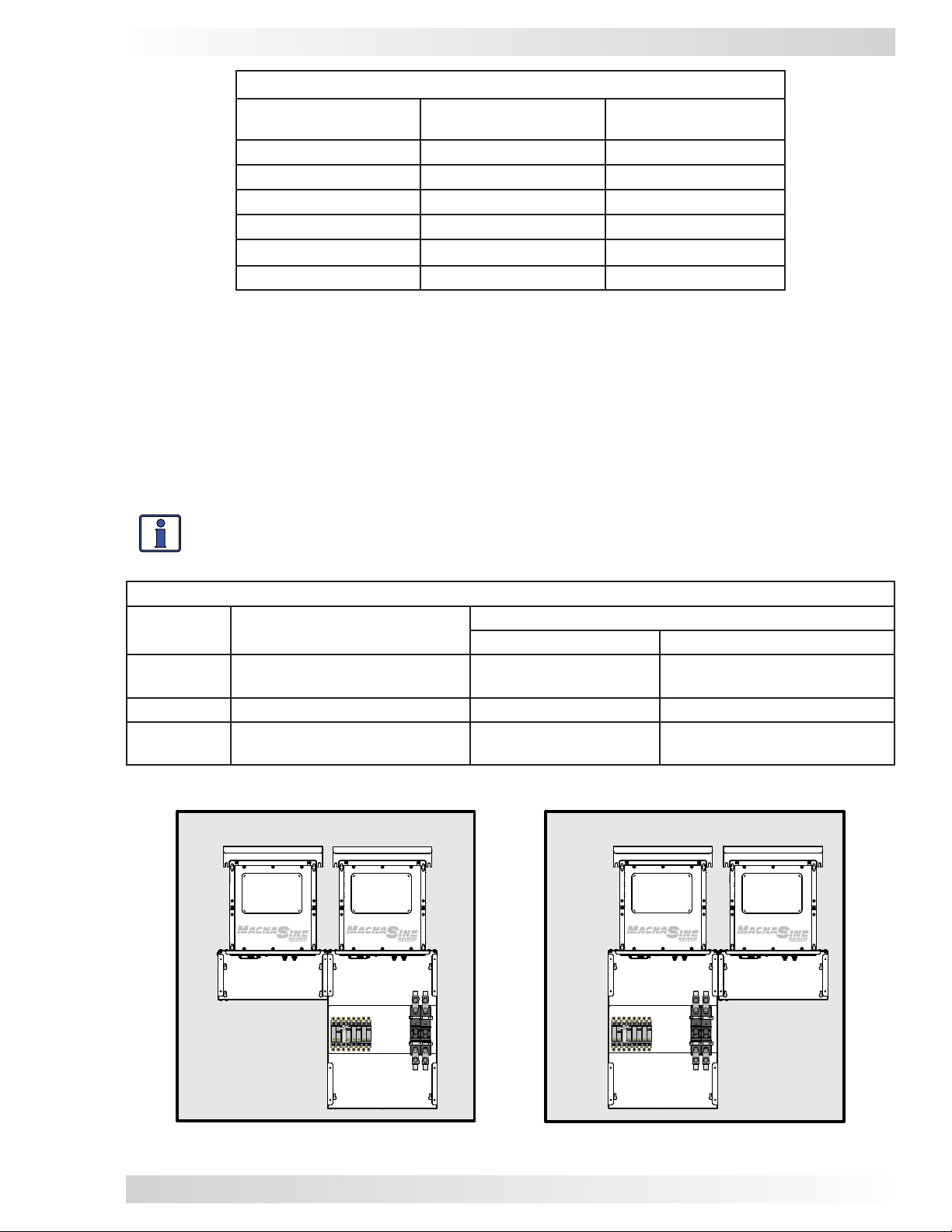
2.2 Available MPX Models
The three models in the MPX Series are: the MPXS-30D, MPXS-60S, and the MPXD-30D (see Figures 2-3
to 2-5). The MPXS-30D model is designed for use with a single MP enclosure (MPSL-30D and MPSH30D), the MPXS-60S is only used with the MPSL-60S, while the MPXD-30D is designed for use with
a dual MP enclosure (MPDH-30D). Each model comes in a left (L) and right (R) version. The ‘right’
version (MPXS-30D-R, MPXS-60S-R, or MPXD-30D-R) is used when the MPX is mounted to the right
of the MP enclosure, and the ‘left’ version (MPXS-30D-L, MPXS-60S-L, or MPXD-30D-L) is used when
the MPX is mounted to the left of the MP enclosure. The left version differs from the right only in that
the length of the supplied DC cables are different to accommodate the difference in distance from
the MP’s DC breaker to the new installed inverter.
Info: The MPXS-60S model is unique in that it provides #6 AC wiring and a single-pole
60 AAC breaker, rather than the #10 AC wiring and 30 AAC double-pole breaker that
comes with the MPXS-30D and MPXD-30D models.
TABLE 2-3, MPX MODELS
MPX
Model
MPXS-30D
(left or right installation)
MPXS-30D-L/MPXS-30D-R MPSL-30D/MPSH-30D
Versions
Used With:
MP Enclosure Inverters
MS4024PAE or MS4448PAE
stacked in parallel
MPXS-60S MPXS-60S-L/MPXS-60S-R MPSL-60S MS4024 stacked in series
MPXD-30D MPXD-30D-L/MPXD-30D-R MPDH-30D
MS4024PAE or MS4448PAE
stacked in parallel
MPXS-60S on left side (MPXS-60S-L) MPXS-60S on right side (MPXS-60S-R)
MS4024
I
NVERTER
MPXS-60S-L
MS4024
I
NVERTER
OR
MS4024
I
NVERTER
MS4024
I
NVERTER
MPXS-60S-R
MPSL-60S
MPSL-60S
Figure 2-3, MPXS-60S Installation Confi gurations
© 2011 Magnum Energy, Inc.
5
Page 10
2.0 Introduction
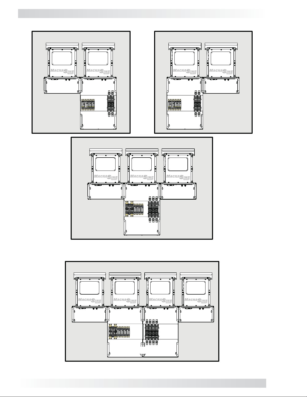
MPXS-30D on left side (MPXS-30D-L)
MS
-PAE
I
NVERTER
MS-PAE
NVERTER
I
MPXS-30D-L
MPSL-30D
MPXS-30D on both sides (MPXS-30D-L & MPXS-30D-R)
MS-PAE
NVERTER
I
OR
MS-PAE
I
NVERTER
MPXS-30D on right side (MPXS-30D-R)
MS-
PAE
I
NVERTER
MS-PAE
I
NVERTER
MPXS-30D-R
MPSL-30D
MS-PAE
NVERTER
I
MPXS-30D-L
MPXS-30D-R
MPSH-30D
Figure 2-4, MPXS-30D Installation Confi gurations
MPXD-30D on both sides (MPXD-30D-L & MPXD-30D-R)
MS-PAE
I
NVERTER
MPXD-30D-L
MS-PAE
I
NVERTER
MS-PAE
I
NVERTER
MS-PAE
I
NVERTER
MPXD-30D-R
MPDH-30D
Figure 2-5, MPXD-30D Installation Confi guration
6
2011 Magnum Energy, Inc.
Page 11
3.0 Installation
3.0 Installation
3.1 Installing the MPX
Info: Installations should be performed by qualifi ed personnel, such as a licensed or
certifi ed electrician. It is the installer’s responsibility to determine which safety codes
apply and to ensure that all applicable installation requirements are followed. Applicable
installation codes vary depending on the location and application of the installation.
WARNING: This manual does not cover all the relevant safety instructions for your entire
MP/MPX system. Review the safety information on pages 1 and 2 of this manual. Refer
to the MP Owner’s Manual (PN: 64-0028) prior to installing the MPX extension.
CAUTION: The MPX/MP enclosures and the inverters are heavy . Remember to use proper
lifting techniques during installation to prevent personal injury.
3.1.1 Preparation
Before proceeding, read the entire Installation section to determine how you are going to install your
MPX extension. The more thorough you plan in the beginning the more time you will save. Proper
planning will also help you avoid common, costly mistakes.
Required Materials and Tools
Materials
• Conduit, strain-reliefs, and appropriate fi ttings • 1/4” mounting bolts & lock washers
• Electrical tape • Wire ties
• Conductors/cables for wiring
Tools
• Miscellaneous screwdrivers • Insulated pliers • Wire cutters/strippers
• Drill and drill bits • Pencil or marker • Multimeter
• Level • 1/2” wrench • Torx driver (T20,T25)
• Torque wrenches • Ratchet drives
Location
Info: When possible, Magnum Energy recommends that if you are installing only one MPX
it should be mounted to the left of the MP enclosure. Mounting the MPX on the right may
prevent you from adding certain manufacturers’ charge controllers in the future.
Only install your enclosure/inverter system in a location that meets the following requirements:
Clean and Dry - System must be mounted indoors in a relatively cool, clean, and dry en vironment.
Ventilation - If installed on the MP enclosure or MPX, the inverters pull in air through the intake
vents. In order to provide full output power and avoid over-temper ature fault conditions do not cover
or block the MPX/MP enclosures’ ventilation openings, or install it in an area with limited airfl ow. At
the minimum, allow 3 inches of clearance to the left and right sides of the MPX/MP enclosures.
Close to the Battery Bank - Locate system as close to the batteries as possible. This ensures the
battery cable length is kept as short as possible. Long DC wires tend to lose effi ciency and reduce the
overall performance of an inverter. However, the MPX/MP enclosures, inverter, and any other equipment
that can spark (or that corrosion could damage) should not be installed in the same compartment/room
as the batteries or mounted where it will be exposed to battery gases. These gases are corrosive and
will damage this equipment; also, if these gases are not ventilated and if allowed to collect, they could
ignite and cause an explosion. Consult your battery supplier for proper installation requirements.
Info: Consult your inverter owner’s manual to determine the proper inverter-to-battery
cable size for the distance that is used. However, this cable must not be sized any smaller
than 0000 (4/0) AWG if the DC disconnect breaker in the MP enclosure will also be used
as the overcurrent device. If a cable smaller than 4/0 AWG is used, an appropriately sized
fuse must be installed to provide overcurrent protection to this smaller cable.
© 2011 Magnum Energy, Inc.
7
Page 12
3.0 Installation
Safe - Keep any fl ammable/combustible material (e.g., paper, cloth, plastic, etc.,) that may be
ignited by heat, sparks or fl ames at a minimum distance of 12 feet away from the MP/inverter
system. Do not install the MPX/MP/inverter system in any area that contains extremely fl ammable
liquids like gasoline or propane, or in locations that require ignition-protected devices. Sparks from
relays, circuit breakers, etc., could ignite the fumes or spills.
Accessible - Do not block access to the front of your system. Maintain at least a 36” (91 cm)
clear space in front to access the AC and DC wiring terminals and connections inside the MPX/MP
enclosure, as they will need to be checked and tightened periodically.
Removing the MPX’s Front Cover
Remove the front cover on the MPX extension using a T25 Torx screwdriver. The screws are #10-32
x 3/8” Pan head, T25 Torx drive, thread cutting screws and the washers are #10 external tooth Star
washers. You will need to reattach the MPX cover once all wiring is completed and tested.
TOP VIEW
BBB
8 1/16"
CC
AABBB
8 15/
64"
LEFT SIDE VIEW
A
8
1/16"
8 1/16"
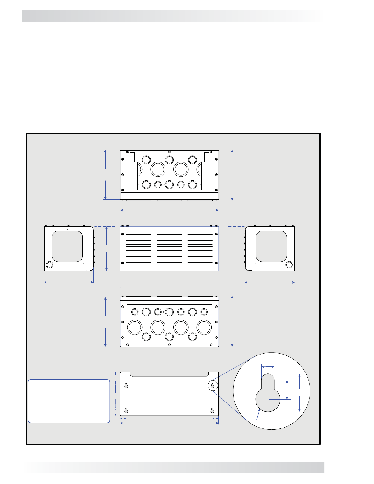
CONDUIT KNOCKOUTS:
A = ½" and ¾" (x6)
B = ¾" and 1" (x6)
C = 1½" and 2" (x4)
7 15/64"
1
2"
4"
1/8
16"
FRONT VIEW
BOTTOM VIEW
AAABBB
C
BB
C
C
BACK VIEW
1
14"
RIGHT SIDE VIEW
A
8 15/64"
A
8 15/64"
C
B
1
KEYHOLE DETAIL
(x4)
0.2
8"
0.412"
0.8145"
0.525"
Figure 3-1, MPX Series Dimensions and Knockout Locations/Sizes
8
© 2011 Magnum Energy, Inc.
Page 13
3.0 Installation
Conduit Knockouts
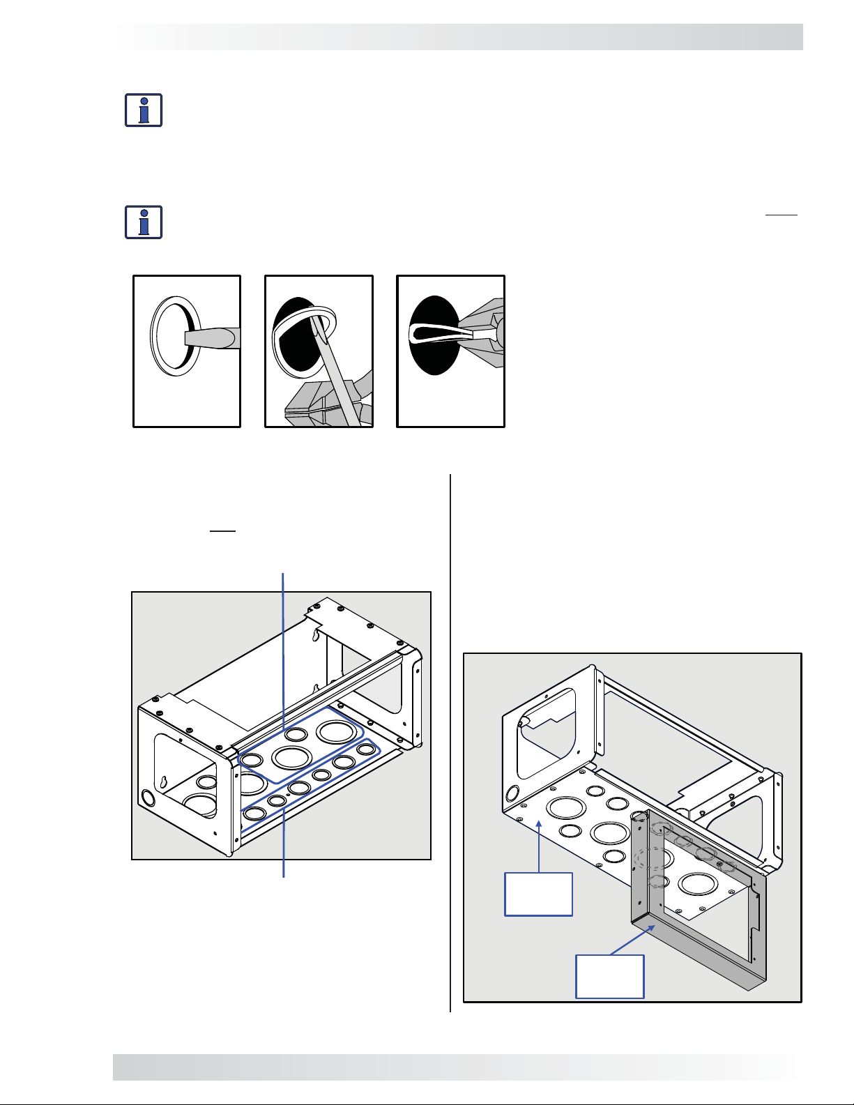
Info: Knockouts can be easily removed by tapping the edge with a straight bladed screw-
driver and a hammer, then twist out with pliers; refer to Figure 3-2. Ensure that no debris
remains inside the MPX after removing the knockouts.
The MPX
3-1 for the location of these conduit knockouts. Select the appropriate knockout that is closest to
the terminal to which you are running the cable/wire (see Figures 3-1 and 3-3).
comes standard with knockouts for 1/2”, 3/4”, 1”, 1 1/2”, and 2” conduits. Refer to Figure
Info: Identify and remove whatever MPX knockouts you will need for your installation prior
to attaching the MPX to the MP enclosure. It is much easier to do this now rather than once
the MPX is attached.
Figure 3-2, Removing
a Knockout
Remove one of these knockouts in order
to run the communication cables from
the router to the inverters.
Do not remove any these front knockouts if the router* is attached to the MPX
(see also Figure 3-4).
Note: The RTR bracket below is shown
mounted on the right side of the MPX. The
bracket can also be mounted on the left side
of the MPX.
Do not attach the RTR bracket to the MPX/
MP enclosure at this time (the bracket will be
attached later in Section 3.1.8).
Bottom
of MPX
RTR
* The router and bracket are only used
if inverters are to be parallel stacked.
bracket
Figure 3-3, Removing MPX Knockouts Figure 3-4, MPX with RTR Bracket
© 2011 Magnum Energy, Inc.
9
Page 14
3.0 Installation
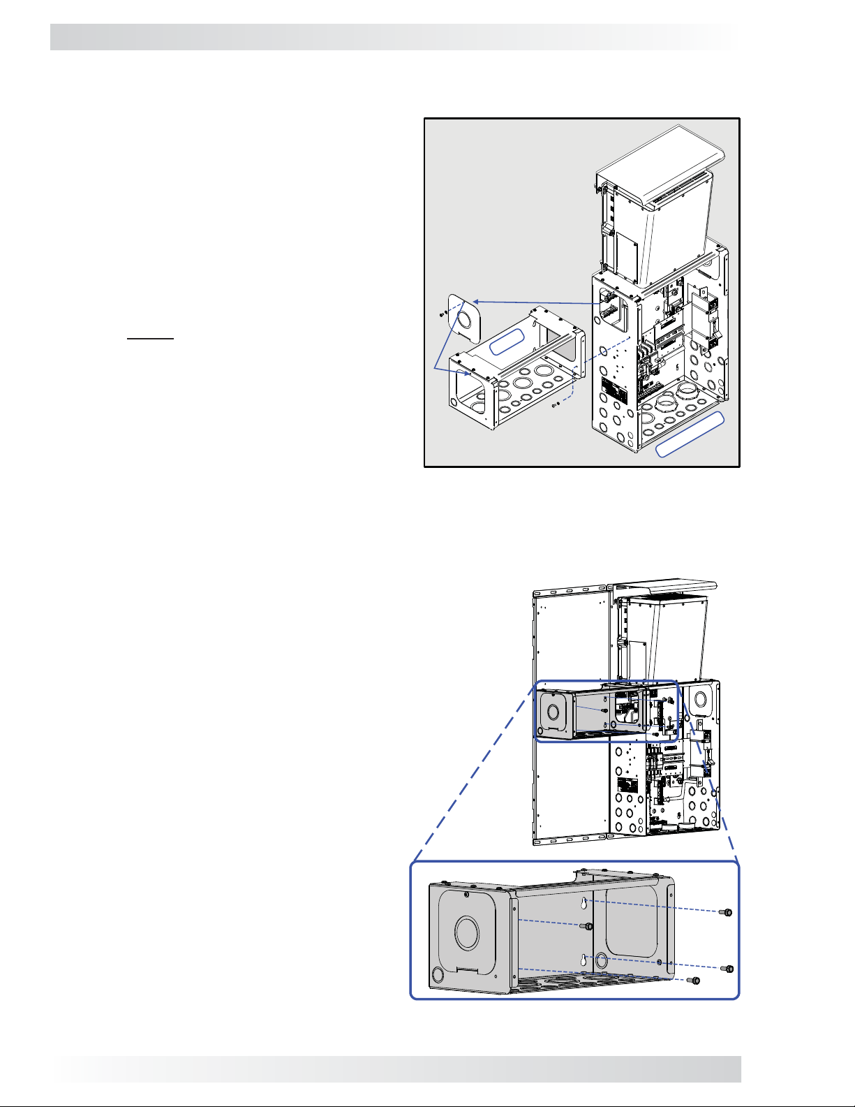
3.1.2 Attaching the MPX to the MP Enclosure
The MPX attaches to the MP enclosure. This provides unit stability when the MP enclosure is mounted to a backplate/sheathing, and also ensures good
metal-to-metal contact for grounding the MPX and
the MP enclosure together.
1. On the upper side of the MP enclosure, remove
the side access plate – the side to which you will
attach the MPX (see Figure 3-5).
2. Using the same screw and lock washer (see
Item A), attach the side access plate to the
side of the MPX (opposite the side of the MPX
that attaches to the MP).
Note: Before attaching the MPX to the MP
enclosure you should have already removed
a knockout from the bottom of the MPX (see
Figure 3-3). This knockout is needed for running the communication cables from the router
to the inverters.
Use the supplied (B) #1032 x 3/8” (T25) T orx screw
and #10 lock washer
(Figure 2-2, Items 5 & 6) to
attach the MPX to the MP
enclosure.
A
MPX
B
3. Use the supplied screw and lock washer (see
Item B) to attach the MPX to the MP enclosure.
The attachment hole is located towards the front
of the (lower) side of the MPX.
Figure 3-5, Attaching the MPX
to an MP Enclosure
3.1.3 Mounting the MP/MPX Enclosure to a Backplate/Wall
The MP enclosure and attached MPX can be mounted on a Magnum backplate or a wall (see the MP
Owner’s Manual for wall requirements).
1. Using eight bolts, screw them halfway into the
backplate/wall in the locations that the MP enclosure and attached MPX will be mounted (align
with each unit’s four keyhole slots).
Note: If you have purchased a Magnum dual
or single backplate, you will be supplied with
the necessary Hex head bolts (1/4-20 x 3/4”) to
mount the MP and MPX units to the backplate.
If you are mounting to a wall, the installer must
provide the appropriate mounting bolts.
2. Hang the MP enclosure and attached MPX onto
the eight bolts using each unit’s keyhole slots
(see Figure 3-6).
3. Tighten the bolts to secure the MP enclosure
and MPX onto the backplate/wall.
BP-S Magnum
Single Backplate
MP Enclosure
Figure 3-6, Mounting the MPX to a Backplate/Wall
10
© 2011 Magnum Energy, Inc.
Page 15

3.0 Installation
3.1.4 Attaching the DC and AC Breakers
Info: The holes on the breaker mounting plate inside the MP enclosure — for Torx screws
that hold the new DC and AC breakers — are NOT pre-threaded. Use a power driver to
screw these self-threading screws into the mounting plate.
WARNING: During normal operation the terminals, busbars, and electrical components
inside the MP enclosure may be energized - DO NOT TOUCH. Disconnect all power sources
before removing the cover.
DC Breaker
CAUTION: The DC break ers must be mounted in a vertical position to meet the specifi ed
trip current and trip delay curve.
The DC breaker is attached within the MP enclosure and functions as the inverter’s DC disconnect switch.
The DC breaker can be used as the battery-to-inverter circuit protection in most installations.
1. Using a T25 screwdriver, remove two of the #10-32 x 3½” Torx screws that secure the existing
DC breaker to the mounting plate – the removed screws should be the two that are adjacent to
where the new DC breaker will be mounted (see Figure 3-7).
2. Place the new DC breaker against the MP’s mounting plate and next to the existing DC breaker
where the two mounting straps are loose.
3. While holding the new DC breaker in place, fi t two new mounting straps over the new DC breaker.
Ensure the holes on the new mounting straps — that are over the new DC breaker — line up with
the holes of the adjacent two existing mounting straps (see Figure 3-8).
4. Insert the two Torx screws that were removed in Step 1 into the aligned holes of the new and
existing mounting straps on the adjacent sides of the breakers, and then tighten to secure the
existing DC breaker. Insert two new #10-32 x 3½” Torx screws into the other side of the new
mounting straps and tighten enough to hold the new DC breaker in place. Do not fully tighten the
screws, that will be done in Step 5 after being aligned.
5. Check for proper breaker alignment by temporarily placing the MP’s front panel co ver over the DC
breakers. If fi t and alignment are correct, tighten all T orx screws to secure the new DC break er.
CAUTION: Be careful not to over-tighten to the point of bending down the tabs on the
mounting straps.
Mounting Plate
(location for
new breaker)
Leave
existing
mounting
straps
(x2)
in place
Note: Figure 3-8 in-
cludes the new breaker’s DC wire connections. Actual connec-
New
mounting
straps
(x2)
tions occur in Section
3.2.
New
torx
screws
(x2)
Remove
screws
adjacent
to new
breaker
location
New
DC
breaker
Existing
mounting
straps
(x2)
Existing
torx
screws
(x2)
Existing
DC
breaker
Fig. 3-7, Removing Breaker Screws Fig. 3-8, Attaching the New DC Breaker
© 2011 Magnum Energy, Inc.
11
Page 16
3.0 Installation
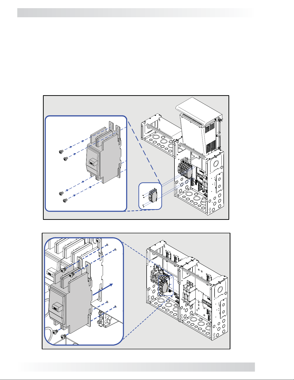
AC Breaker
The AC breaker is attached within the MP enclosure and functions as the inverter’s AC input disconnect switch.
1. While holding the new AC breaker against the MP’s mounting plate, align the breaker’s four mounting holes with the enclosure’s mounting holes (see Figure 3-9). Note: The AC breakers are always
installed in the left enclosure of a MP dual enclosure (see Figure 3-10).
2. Use the supplied four #8-32 x 1/4” T20 screws (Figure 2-2, Item 4) to hold the AC breaker in
place. Do not fully tighten the screws, that will be done in the next step after ensuring proper
alignment with the MP enclosure’s cover.
3. Check the AC breaker alignment by temporarily placing the MP’s front panel cover over the AC
breakers. If the fi t and alignment are correct, tighten all Torx screws to secure the new AC breaker.
Use four #8-32 x ¼”
(T20) Torx screws
Figure 3-9, Attaching the New AC Breaker Within a MP Single Enclosure
Figure 3-10, Attaching the New AC Breaker Within a MP Dual Enclosure
12
© 2011 Magnum Energy, Inc.
Page 17
3.0 Installation
3.1.5 Connect and Separate Inverter AC Wires
Prior to mounting the second inverter on the MP enclosure, connect the AC wires provided in the
MPX AC wire kit (see Figure 2-1, Item F and Table 2-1) to the inverter’s AC wiring terminal (see
the inverter owner’s manual or the MP Owner’s Manual for guidance in connecting the AC wires
inside the inverter). Before connecting the AC wires, separate them into two wire bundles (inverter
AC input and inverter AC output) to help ensure they are connected correctly after the inverter is
mounted on the MP enclosure.
It is possible to connect these wires after the inverter is mounted. However, you have more space and
easier access to the wiring terminal when the inverter’s AC wires are connected before mounting –
especially when installing multiple inverters side-by-side on an MP enclosure system. Replace the
AC wiring access plate once you have connected the wires inside the inverter.
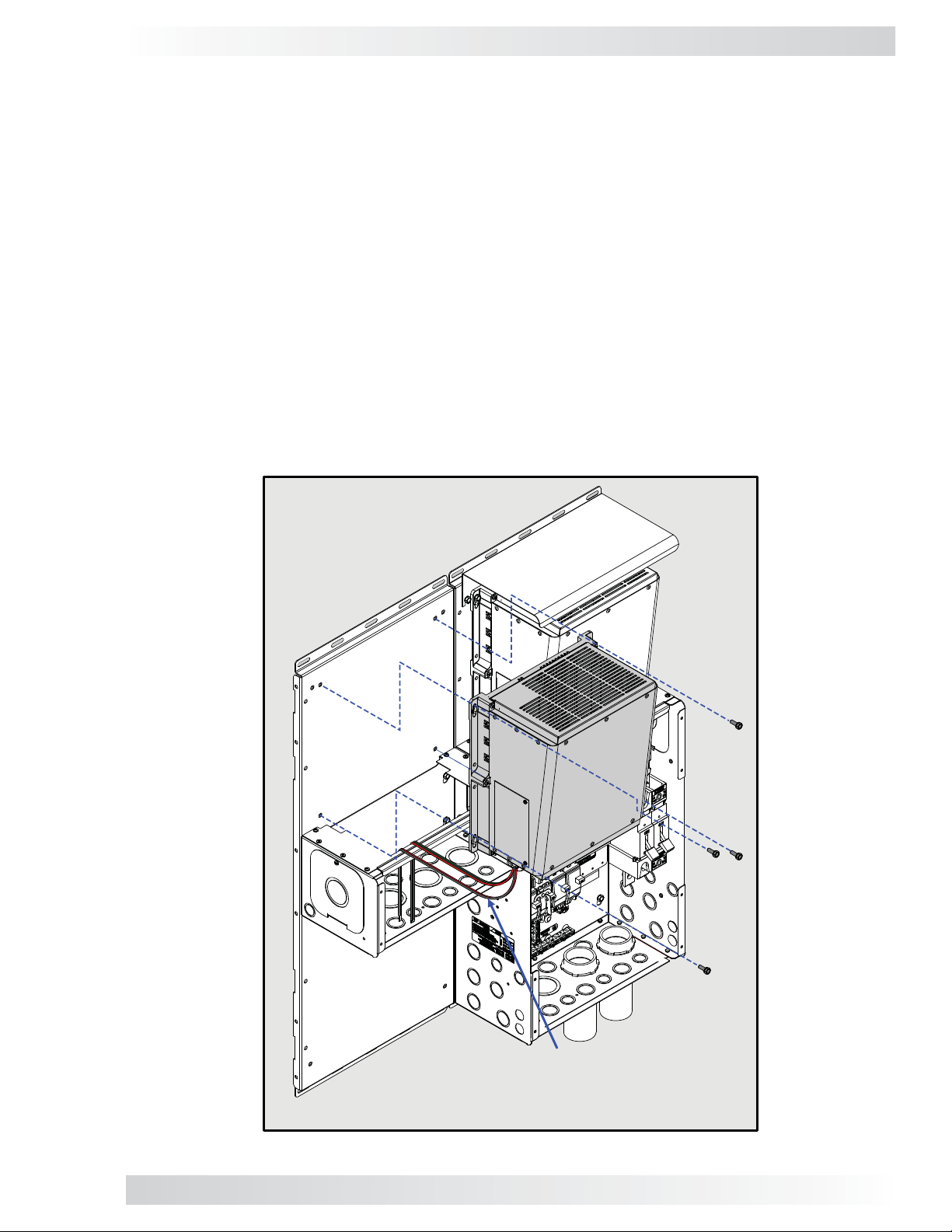
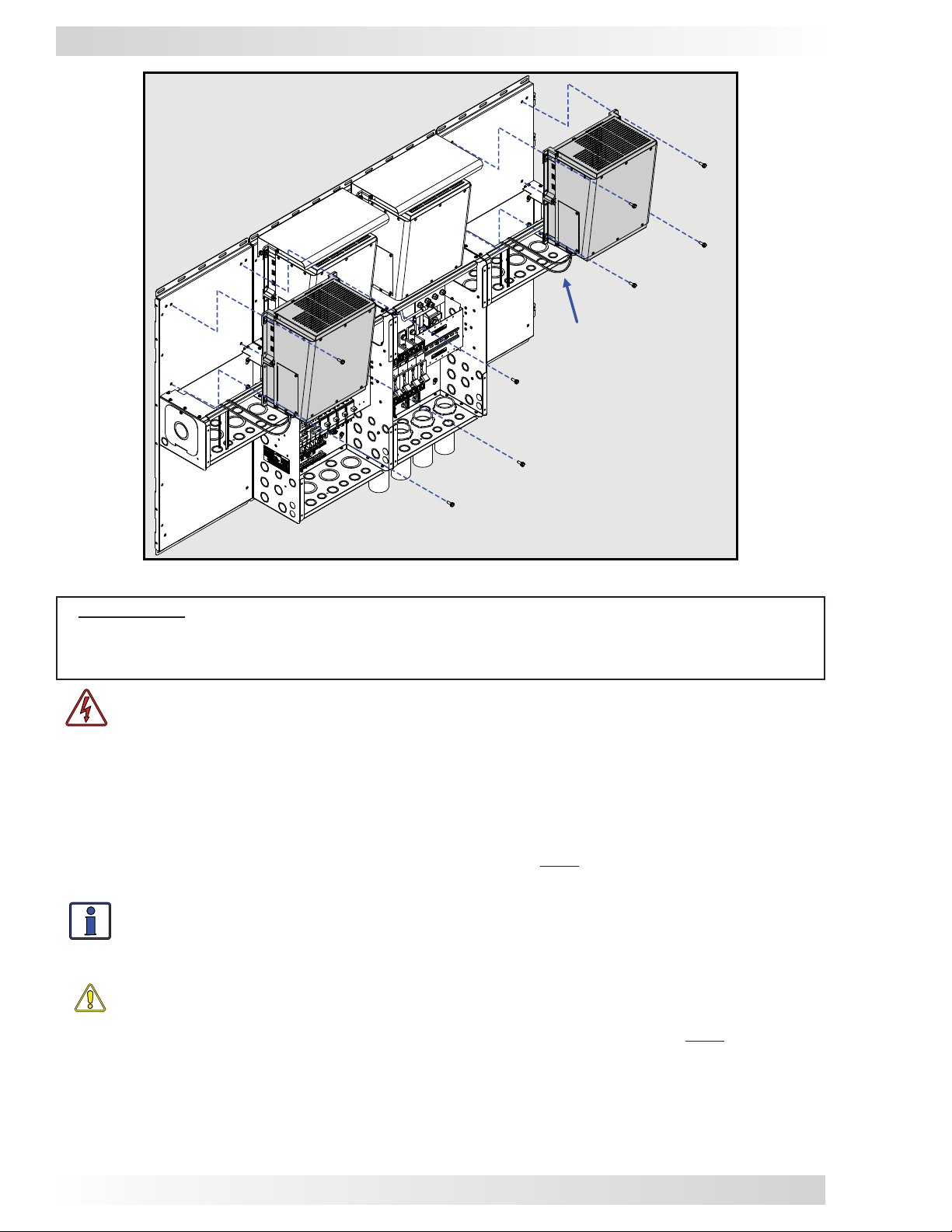
3.1.6 Mounting the Second Inverter onto the MPX
The additional inverter fi ts on top the MPX and is secured to the backplate/wall (Figures 3-11 & 3-12).
Note: Before mounting, pull the unconnected ends of the AC wiring outside of the inverter and
through the MPX enclosure (see Figure 3-12).
1. Place the Magnum inverter on top of the MPX.
2. Secure it to the backplate/wall using four Hex head bolts and the inverter’s keyhole slots.
3. Tighten the Hex head bolts to secure the inverter to the backplate/wall.
Note: Prior to mounting, connect the AC input
and output wires within the new inverter (refer
to your inverters owner’s manual), and then
route the wiring through the MPX.
Figure 3-11, Mounting the Second Inverter on the MPX
© 2011 Magnum Energy, Inc.
13
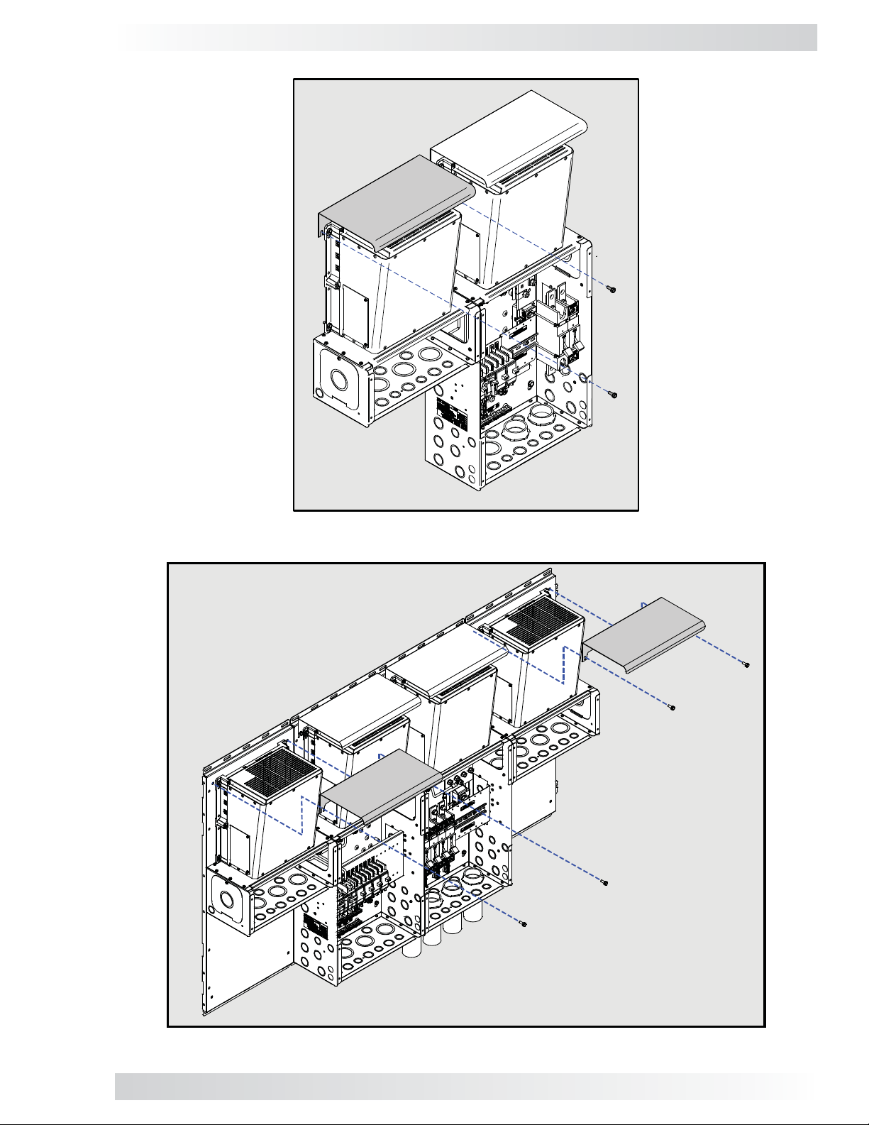
Page 18
3.0 Installation
Note: Prior to mounting,
connect the AC input and
output wires within each
new inverter (refer to your
inverter owner’s manual),
and then route the wiring
through the MPX.
Figure 3-12, Mounting Multiple Inverters on the MPX
IMPORTANT: If the inverter is ever removed from the top of the MPX for service and the
AC bypass breaker is used to continue to power the inverter loads, attach the knockout plate
(provided with the MP enclosure) to the top of the MPX for use as a safety plate to prevent
accidental access to live electrical circuits inside the MPX.
WARNING: If the knockout plate is used as a safety plate, the battery cables from the
top of the DC disconnect must be prevented from touching the metal knockout plate or
a short circuit to the battery bank may occur – causing lethal currents. Either remove
these cables or isolate them (i.e., using electrical tape/rubber caps), do not rely ONLY
on turning the DC disconnect switch to OFF.
3.1.7 Attaching the Inverter Hood
The inverter hood is designed to prevent objects from falling inside the top vents of the inverter,
which can cause damage. For installations where the inverter is mounted on a vertical surface (DC
terminals facing down) — such as a MP enclosure — the hood must be mounted above the inverter
in order to meet UL regulatory requirements.
Info: The inverter hood does not mount to the inverter chassis, it must be mounted to the
backplate/wall. Mounting bolts are included if a Magnum backplate has been purchased.
If no backplate, the installer must supply the bolts – the mounting slots on the hood will
accept up to a maximum 1/4” screw/bolt.
CAUTION: The inverter hood is not to be used as a drip shield to prevent water drops
from entering the inverter.
Refer to Figures 3-13 & 3-14 to install the hood. The bottom edge of the hood must be mounted
fl ush against the top of the inverter. This is the optimal position for minimizing the risk of objects
falling into the inverter, and at the same time providing the clearance needed for air fl ow from the
top vents of the inverter. Do not place anything on top of the inverter hood that might cause it to
bend downward, or place anything on the sides that might restrict air fl ow through the inverter.
1. Screw two bolts/screws halfway into the backplate/wall where the hood will be mounted.
2. Place the inverter hood on these screws, and then tighten securely.
14
© 2011 Magnum Energy, Inc.
Page 19
3.0 Installation
Figure 3-13, Attaching the Inverter Hood
Figure 3-14, Attaching Multiple Inverter Hoods
© 2011 Magnum Energy, Inc.
15
Page 20

3.0 Installation
3.1.8 Attaching the Router Bracket
The Magnum router can be easily attached to the MP and MPX enclosures using the router bracket.
The router bracket comes with four screws (#8 x 32 x 3/8” T15 drive) for mounting; one for attaching the bracket to the MPX, and three for attaching the bracket to the MP enclosure (router br acket
and hardware provided with MP enclosure). Refer to Figure 3-15.
Use the Torx drive screws
provided with the router bracket
Figure 3-15, Attaching the Router Bracket
3.1.9 Attaching the Router to the Bracket
The router is easily attached to the router bracket using the four screws (#8-32 x 1/2” Phillips drive)
in the router bracket kit provided with the MP enclosure. Refer to Figure 3-16 to attach the router
to the bracket.
Use the four Phillips screws
provided to attach the router
to the router bracket
Figure 3-16, Attaching the Router to the Bracket
16
© 2011 Magnum Energy, Inc.
Page 21

3.0 Installation
3.2 Wiring the MPX
This section covers installing AC, DC, and communication wiring for each MPX model (Table 3-1).
TABLE 3-1, MPX WIRING TABLE
MPX Model MP Enclosure
Used With:
MPXS-30D MPSL-30D Figure 3-18a Figure 3-18b Figure 3-18c Figure 3-18d Figure 3-18e
MPXS-30D MPSH-30D Figure 3-19a Figure 3-19b Figure 3-19c Figure 3-19d Figure 3-19e
MPXS-60S MPSL-60S Figure 3-21a Figure 3-21b Figure 3-21c Figure 3-21d Figure 3-21e
MPXD-30D MPDH-30D Figure 3-22a Figure 3-22b Figure 3-22c Figure 3-22d Figure 3-22e
*- ‘External’ refers to wiring that is required outside the MP/MPX panel (i.e., wiring to loads, grid/gen input wiring)
3.2.1 Wiring Guidelines
This section provides general information on the AC wiring to/from the new inverter, from the incoming AC source, and to the outgoing AC distribution panel (i.e., inverter sub-panel).
IMPORTANT: All wiring should meet local codes and standards and be performed by qualifi ed personnel such as a licensed electrician.
CAUTION: Before installing any AC wiring, review all safety information in the MP Owner’s
Manual (PN: 64-0028) and at the beginning of this manual, and the information below
to ensure a safe system:
• The AC wires must be appropriately sized, and must be no less than #10 AWG (5.3
mm2) gauge copper wire and be approved for residential wiring.
• DO NOT connect the Magnum inverter’s output to an AC power source. This could
cause severe damage to the inverter and is not covered under warranty.
Inverter
AC Wiring
External*
AC Wiring
Inverter
DC Wiring
Battery Bank
DC Wiring
Communica-
tions Wiring
WARNING: To reduce the risk of fi re, do not connect a 120V AC only inverter to both
busbars in an AC load center (circuit breaker panel) having multi-wire branch circuits
connected. Every circuit connected to a 120V AC panel must have its own neutral; otherwise, currents on shared neutrals will add rather than subtract – ov erloading the neutral
conductor.
The AC and DC wires into and out of the MP enclosure and the MPX extension must be protected as required by code. This can be done by using jacketed wires or by feeding wires through conduit.
Info: If using a Magnum inverter, and the AC wires are individual conductors (i.e., not
jacketed), the strain reliefs on the inverter can be replaced with 3/4” grommets.
• Use proper clamps or other approved methods for securing the cable/conduit to the enclosure.
• The MP enclosure is specifi cally approved/designed for both AC and DC wiring. However, where
DC wiring must cross AC or vice-versa, try to make the wires at the crossing point 90° to one
another.
• Use only copper wires with a minimum rating of 150V , 75°C if only 120V AC power is being used;
or, with a minimum rating of 300V, 75°C if 120/240V AC power is being used.
• In a system where one conductor is grounded, the wire colors on the DC side and the AC side
are the same. The insulation on all grounded conductors (DC negative/AC neutral) must be
white, gray, or any color except green if marked with white at each termination (marking only
allowed on 6 AWG or larger conductors). The equipment grounding conductors must be bare
(no insulation), or have green or green with yellow-striped insulation or identifi cation. The hot
ungrounded conductor (DC positive/AC hot) is usually red or black.
• Terminals containing more than one conductor must be listed for multiple conductors.
• The connectors or terminals used on fl exible, fi ne-stranded conductors must be specifi cally
marked or labeled for use with fi ne-stranded conductors.
• The MPX/MP enclosures include wires (along with communication cables) with insulation rated for
at least 300 volts, which allows 120/240V AC inverters to be installed. If installing a 120/240V
AC inverter, the installer must also provide wires (both power and communication) with the
insulation rated for at least 300 volts.
© 2011 Magnum Energy, Inc.
17
Page 22

3.0 Installation
AC Connections
To view the AC connection points inside the MP enclosures, review Figures 3-18a/b and 3-19a/b for
the MPSL-30D and MPSH-30D models, Figure 3-21a/b for the MPSL-60S model, or Figure 3-22a/b
for MPDH-30D model.
If using an MS-PAE Series inverter, the full AC continuous pass-thru capacity of these inverters is 30
amps for each AC leg (AC LEG 1 and AC LEG 2), and requires a maximum 30 amp breaker on each
AC input to protect the inverter’s inputs. This correlates with the MPSL-30D, MPSH-30D, and the
MPDH-30D enclosures, which include a dual 30 amp input inverter breaker and a minimum cable size
of #10 AWG in conduit.
In MS4024 inverters, the AC LEG 1 and AC LEG 2 may be combined to obtain a 60 amps pass-thru
capability. When tying the AC LEG 1 and AC LEG 2 together for a 60 amp continuous pass-thru capability, the AC input to the inverter requires a 60 amp breaker. This correlates with the MPSL-60S
model, which includes a single 60 amp breaker and requires a minimum cable size of #6 AWG in
conduit. Refer to Figure 3-20a for info on wiring to the MS4024 inverter.
If you are using other circuit breakers/wire sizes, refer to the appropriate electrical codes for proper
sizing requirements.
DC Cable Connections
Before proceeding with the DC wiring, review the instructions in Figure 3-17 to ensure proper DC
cable stacking and connections. Do not put anything between the DC cable ring lug and the battery
terminal post or the fl at metal part of the inverter’s DC terminal. When connecting the DC cable
to the battery or inverter DC terminals, the cable should be placed directly against the inverter or
battery terminals. Incorrectly installed hardware causes a high resistance connection which could
lead to poor inverter/charger performance, and may melt the cable and terminal connections.
Make sure to properly connect the DC cables and correctly stack the hardware. Tighten the terminal
connections from 10 to 12 ft lbf (13.6 to 16.3 N-m).
CAUTION: The DC terminal and Flange/Kep nuts supplied with the inverter are made
of stainless steel, which have a high likelihood of seizure. To help prevent the bolt and
nut from seizing — causing the bolts to strip or snap/break-off — the use of anti-seize
lubricant is highly recommended.
Info: If antioxidant grease or spray is used, apply it after all the connections have been
made and are properly tightened.
Info: A 1/2-inch wrench or socket is used to tighten the 5/16-18 SAE Flange/Kep nuts.
IMPORTANT: Magnum accessories (ME-ARC, ME-RTR, ME-AGS, and ME-BMK) each use a
communication chip to talk with the inverter. This communication chip is powered through the
communication lines using the B+ (battery positive) and B- (battery negative) supply. We hav e
found that customers are removing the battery negative circuit (B-) while the battery positive
circuit (B+) is still connected; or, they are connecting the battery positive (B+) before connecting battery negative (B-). When accessories are connected to the inverter and B+ is connected
or disconnected to the inverter without a return path (i.e., B-), the communication chips/lines
become the DC return path to the battery – causing permanent damage to all connected accessories on the network.
You should not ha ve any issue with communication circuits when using the MP/MPX panels. This
is because when you open the Inverter Disconnect Breaker on the MP to power-down the system you are opening the B+ circuit while all B- circuits remain connected. Once the system is
powered-down, you can connect and disconnect communication cables as needed. When you are
fi nished removing/adding accessories and comm cables, you can turn the Inverter Disconnect
Breaker back on to resume operation, which connects the B+ circuits (with B- circuits already
connected).
In summary: Ensure all battery negative (B-) circuits are connected before connecting
or disconnecting battery positive (B+).
18
© 2011 Magnum Energy, Inc.
Page 23

MPX
Inverter
#2
Enclosure
MP
Inverter
#1
3.0 Installation
INVERTER DC NEGATIVE AND POSITIVE CONNECTIONS
Inverter Hardware Stack-up:
Inverter DC terminals
1
2
3
INVERTER NEGATIVE TO SHUNT BUSBAR (TOP) DC POSITIVE CONNECTION
2
3
4
5
1
INVERTER POSITIVE TO INVERTER DC BREAKER (TOP) CONNECTION
3
2
4
1
BATTERY POSITIVE TO INVERTER DC BREAKER (BOTTOM) CONNECTION
1
3
2
4
1
Inverter cable lugs
2
[(-) to shunt busbar,
(+) to inverter DC breaker]
5/16-18 nut (Flange or Kep)
3
DO NOT place anything
between the inverter DC
terminals and the inverter
cable lugs
Top of Shunt Busbar Hardware
1
2
3
4
5
between the DC shunt busbar
and the negative inverter cable
Top of DC Breaker Hardware
1
2
3
4
Bottom of DC Breaker Hardware
1
2
3
4
Stack-up:
DC shunt busbar (top)
Hex bolt (3/8-16-3/4")
Negative (-) battery cable lug
Split-lock washer
3/8-16 nut
DO NOT place anything
Stack-up:
DC breaker (top) terminal
Positive (+) inverter cable lug
Split-lock washer
Hex bolt (3/8-16-3/4")
DO NOT place anything
between the DC breaker
terminal and the positive
inverter cable lug.
Stack-up:
DC breaker (bottom) terminal
Positive (+) battery cable lug
Split-lock washer
Hex bolt
between the DC breaker
terminal and the positive
(3/8-16-3/4")
DO NOT place anything
battery cable lug.
.
lug.
BATTERY NEGATIVE TO SHUNT BUSBAR (BOTTOM) CONNECTION
Bottom of Shunt Busbar
Hardware Stack-up:
4
1
2
3
5
1
DC shunt busbar (bottom
2
Hex bolt (3/8
3
Negative (-) battery cable lug
4
Split-lock washer
3/8-16 nut
5
DO NOT place anything
between the DC shunt busbar
and the negative battery cable
-16-3/4")
lug.
Figure 3-17, DC Cable Connections
© 2011 Magnum Energy, Inc.
)
19
Page 24

3.0 Installation
3.2.2 Wiring the MPXS-30D
The following steps are basic guidelines for installing and connecting the AC, DC, and communication wiring for the MPXS-30D (used with MPSL-30D or MPSH-30D enclosures).
WARNING: To prevent electrical shock, make sure all AC power (inverter, generator, or
utility) is off before making any AC connections inside the MP enclosure.
MPXS-30D AC Wiring
This section provides information on the AC wiring to/from the inverters, and to/from the main panel
and sub-panel. The MPX kit includes strand B wires for wiring to the AC terminals in the MP enclosure. The HOT 1 and HOT 2 wires into/out of the inv erter are longer than needed. This allows you to
cut and use the two excess wire lengths (one black and one red, or one black w/stripe and one red
w/stripe) for routing AC wires from the bottom of the AC breaker to the MP’s busbar terminals. See
Table 2-1 for AC wire size, color, length, and routing location.
Inverter AC Input Wiring (see Figure 3-18a - MPSL-30D, Figure 3-19a - MPSH-30D)
1. Route and attach a black wire from the top right terminal of each of the MP enclosure’s new AC input
breakers to each inverter’s AC HO T 1 IN terminal (Master, Slave 1, and if MPSH-30D enclosure, Slave 2).
2. Route and attach a red wire from the top left terminal of each of the MP enclosure’s new AC
input breakers to each inverter’s AC HOT 2 IN terminal.
3. Route and attach a green wire from the MP enclosure’s GROUND busbar to each inverter’s AC
GROUND terminal.
Inverter AC Output Wiring (see Figure 3-18a - MPSL-30D, Figure 3-19a - MPSH-30D)
1. Route and attach a black w/white stripe wire from the MP enclosure’s INV HO T 1 OUT busbar to
each inverter’s AC HOT 1 OUT terminal (Master, Slave 1, and if MPSH-30D enclosure, Slave 2).
2. Route and attach a red w/white stripe wire from the MP enclosure’s INV HOT 2 OUT busbar to
each inverter’s AC HOT 2 OUT terminal.
3. Route a white wire from the MP enclosure’ s AC NEUTRAL busbar to each inverter’s AC NEUTRAL terminal.
Bottom AC Breaker Wiring (see Figure 3-18b - MPSL-30D, Figure 3-19b - MPSH-30D)
1. Route and attach a black wire from the bottom right terminal of each of the new AC input
breakers to the MP enclosure’s AC LEG 1 IN busbar (Master, Slave 1, and if a MPSH-30D
enclosure, Slave 2).
2. Route and attach a red wire from the bottom left terminal of each of the new AC input breakers
to the MP enclosure’s AC LEG 2 IN busbar.
External AC Main Panel Wiring (see Figure 3-18b - MPSL-30D, Figure 3-19b - MPSH-30D)
1. Route and attach a black wire from MP enclosure’s AC LEG 1 IN busbar to the main AC electrical panel.
2. Route and attach a red wire from the MP enclosure’s AC LEG 2 IN busbar to the main AC electrical panel.
3. Route and attach a green wire from the MP enclosure’s GROUND busbar to the main AC electrical
panel’s Ground busbar.
4. Route and attach a white wire from the MP enclosure’s AC NEUTRAL busbar to the main AC
electrical panel’s Neutral busbar.
External AC Sub-Panel Wiring (see Figure 3-18b - MPSL-30D, Figure 3-19b - MPSH-30D)
1. Route and attach a black wire from the MP enclosure’s AC LEG 1 OUT busbar to the AC electrical
sub-panel.
2. Route and attach a red wire from the MP enclosure’s AC LEG 2 OUT busbar to the AC electrical
sub-panel.
3. Route and attach a green wire from the MP enclosure’s GROUND busbar to the AC electrical
sub-panel’s Ground busbar.
4. Route and attach a white wire from the MP enclosure’ s AC NEUTRAL busbar to the AC electrical
sub-panel’s Neutral busbar.
AC Wiring Inspection
After verifying all AC connections are correct — and all AC terminal screws are torqued correctly —
replace the covers on the main electrical panel/sub-panel.
20
© 2011 Magnum Energy, Inc.
Page 25

3.0 Installation
MPXS-30D DC Wiring
This section covers the DC wiring to/from the inverters, and from the battery bank.
WARNING: During normal operation, the terminals, busbars, and electrical components
inside the MP enclosure may be energized – DO NOT TOUCH. Disconnect all power sources
before removing the cover.
WARNING: Use precaution when working with the DC/battery system, even though it is
a “low voltage” system signifi cant hazards may be present, particularly if short circuits
occur.
CAUTION: DO NOT connect the battery cables to the battery bank until all wiring to
the inverters and inside the MP/MPX enclosures is complete, and the correct DC voltage
and polarity have been verifi ed.
Installing DC Cables from Inverters to MP (see Fig. 3-18c - MPSL -30D, Fig. 3-19c - MPSH-30D)
IMPORTANT: Coordinate the DC wiring to each inverter from each DC breaker such that the
far left inverter (Master) is connected to the far left breaker (Master DC breaker), and the
second inverter (Slave 1) is connected to the second DC breaker (Slave 1 break er), and so on.
1. Route a DC positive cable (red) from each inverter into the MP enclosure.
2. Connect the end of the DC positive cable (red) to the inverter’s positive DC terminal.
3. Connect the other end of the DC positive cable (red) to a DC circuit breaker’s top terminal.
4. Route a DC negative cable (black) from each inverter into the MP enclosure.
5. Connect the end of the DC negative cable (black) to the inverter’s negative DC terminal.
6. Connect the other end of the DC negative cable (black) to the top of the DC shunt’s busbar.
7. Route an appropriately sized DC equipment ground wire from each new inverter’s DC GROUND
terminal to the DC GROUND busbar in the MP enclosure.
8. Verify all DC connections are torqued from 10 to 12 ft lbf (13.6 to 16.3 N-m).
9. Once the DC connections are correctly wired and tested, coat the terminals with an approved
anti-oxidizing coating.
Installing the DC Cables From the Battery Bank to the MP Enclosure (see Figure 3-18d MPSL-30D, Figure 3-19d - MPSH-30D)
IMPORTANT: Damage may occur if DC power is connected to the MP enclosure before the
Communication wiring is completed. DO NOT connect the DC cables from the MP enclosure
to the battery bank until: 1) all DC, AC, and Comm wirings are completed, 2) the correct DC
and AC overcurrent protection have been installed and, 3) the correct DC voltage and polarity
have been verified.
WARNING: Ensure all AC and DC breakers are switched OFF before connecting or disconnecting the battery cables, and that all AC and DC power is disconnected from the
inverter.
WARNING: Lethal currents will be present if the positive and negative cables attached
to the battery bank touch each other. During the installation and wiring process, ensure
the cable ends are insulated or covered to prevent touching/shorting the cables.
CAUTION: The Magnum inverter is NOT reverse polarity protected, if this happens the
inverter will be damaged and will not be covered under warranty. Before making the
fi nal DC connection from the MP enclosure down to the battery bank, verify the correct
battery voltage and polarity by using a voltmeter. If the positive (+) terminal of the battery is connected to the negative (–) busbar of the MP enclosure and vice versa, severe
damage will result. Ensure the cables are color-coded to avoid polarity confusion.
1. Route a DC positive battery cable (red) from the battery bank thru the bottom of the MP
enclosure for each inverter.
2. Connect the end of each DC positive battery cable (red) to a DC circuit breaker’s bottom battery
positive connection.
© 2011 Magnum Energy, Inc.
21
Page 26

3.0 Installation
3. Route a DC negative battery cable (black) from the battery bank thru the bottom of the MP enclosure
for each inverter.
4. Connect the end of each DC negative battery cable (black) to the battery negative connection (DC
shunt’s bottom busbar).
5. Route an appropriately sized DC equipment ground wire from the ground terminal in the battery
bank enclosure to the DC ground terminal in the MP enclosure.
6. Route an appropriately sized DC grounding wire (green or bare wire) from the DC GROUND busbar
in the MP enclosure to the system ground (see the MP owner’s manual for information on sizing and
connecting the system ground wire).
7. Ensure the DC wire connections (to the inverter, DC circuit breaker, and DC shunt) are fl ush on the
surface of the DC terminals and the hardware used to hold these connections are stacked correctly
(see Figure 3-17); and then securely tighten these connections.
IMPORTANT: Only after the entire installation is complete and all connections are verifi ed,
should the DC circuit breaker be closed to provide power to the inverters.
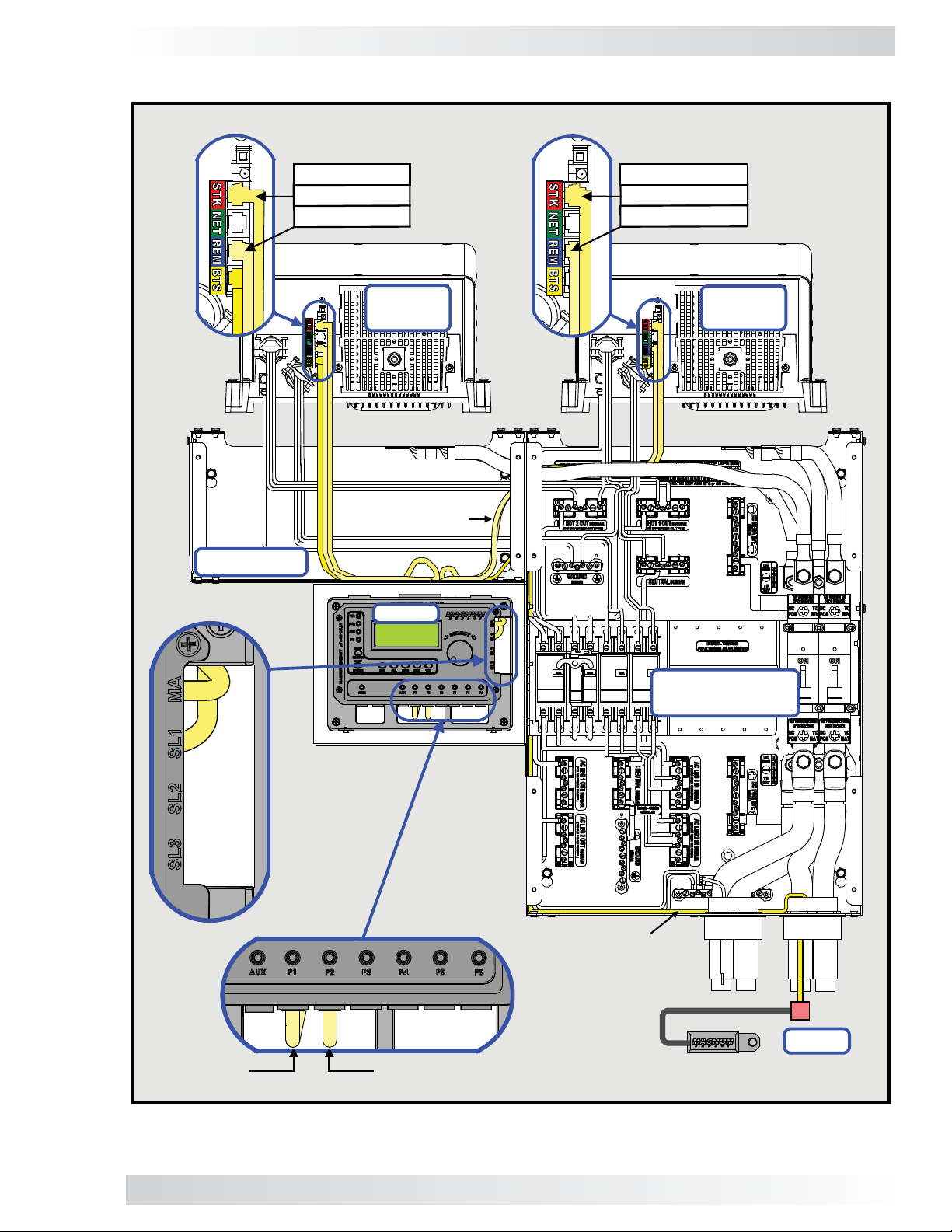
MPXS-30D Communication Wiring
Each MPXS-30D kit includes a remote cable and a stacking cable for connecting to a router. The
Magnum router comes with two CAT 5 stacking cables and two RJ11 remote cables. The MP enclosure
comes with an extension cable for connecting the inverter to a Battery Temperature Sensor (BTS).
Connecting Remote Cables to Router (Figure 3-18e - MPSL-30D, Figure 3-19e - MPSH-30D)
1. Using the supplied RJ11 remote cables, route a cable from each inverter through the MPX to
the attached router.
2. Connect one end of each remote cable to the Remote (blue label) port on each installed inverter.
3. Connect the other end of each remote cable to its respective comm port (P1-P6) on the router.
Info: It is recommended that the Master inverter be connected to Port 1, Slave 1 to P ort 2
etc., in order to k eep tr ack of which inv erter is displayed on each port.
Connecting Stacking Cables to Router (Figure 3-18e - MPSL-30D, Figure 3-19e - MPSH-30D)
1. Using the supplied stacking (CAT 5) cables, route a cable from each inverter through the MPX
to the attached router.
2. Connect one end of each stacking cable to the Stack Port (red label) on each installed inverter.
3. Connect the other end of each stacking cable to its respective CAT 5 port on the router (MA,
SL1, SL2, and SL3 ports for the appropriate number of installed inverters).
Info: At least one CAT 5 cable must be plugged into the router’s MA port in order for the
router to operate any inverters.
Battery Temperature Sensors (BTS) (Figures 3-18e - MPSL-30D, Figure 3-19e - MPSH-30D)
The Battery T emperature Sensor provides the inv erter with precise battery temperature information
that enables the batteries to be correctly charged under extreme temperature changes. If the BTS
is not installed and the batteries are subjected to large temperature changes, battery life may be
shortened.
1. Using the supplied extension cable, route the cable from the Master inverter through the MPX
and the MP enclosure to the BTS.
Info: When the inverters are installed in parallel, the BTS must be connected to the
Master inverter.
2. Connect one end the extension cable to the Battery Temp Sensor port (yellow label) on the
Master inverter.
3. Connect the other end of the extension cable to the RJ-11 connector on the BTS.
Connecting the DC Cables from the MP Enclosure to the Battery Bank
Once all the wiring is completed, connect the DC cables from the MP enclosure to the battery bank.
22
© 2011 Magnum Energy, Inc.
Page 27

Slave
(SL1)
Series
MS-PAE
Inverters
AC INPUT
(to Slave)
Black
Red
Green
Black w/ Stripe
White
Red w/ Stripe
AC OUTPUT
(from Slave)
3.0 Installation
Black
Red
Black
Red
Enclosure
MPSL-30D
SL1
MA
INPUT Breaker
Slave 1 Inverter AC
INPUT Breaker
Master Inverter AC
(MA)
Master
AC INPUT
(to Master)
Black
Red
Green
Black w/ Stripe
White
Red w/ Stripe
MPXS-30D
AC OUTPUT
(from Master)
TO MPSL-30D:FROM INVERTER
Router
:
WIRE
GROUND busbar
AC INPUT breaker
AC INPUT breaker
AC NEUTRAL busbar
INV HOT 2 OUT busbar
INV HOT 1 OUT busbar
AC INPUT
AC INPUT
AC INPUT
AC OUTPUT
AC OUTPUT
AC OUTPUT
RED
BLACK
WHITE
RED w/STRIPE
BLACK w/STRIPE
GREEN
Figure 3-18a, MPXS-30D / MPSL-30D Inverter AC Wiring
© 2011 Magnum Energy, Inc.
23
Page 28

3.0 Installation
Master Inverter AC
INPUT Breaker
MPSL-30D
.Red
Enclosure
Slave 1 Inverter AC
INPUT Breaker
.Red
.Black
.Black
.Black
LEG
1
IN
OFF
OFF
OFF
OFF
.Red
LEG
.White
2
IN
OFF
OFF
.Green
NEU
IN
ON
ON
ON
ON
ON
ON
ON
ON
.White
GND
ON
ON
AC Sub-Panel
(Inverter Loads)
OFF
OFF
OFF
OFF
AC Main Panel
(AC Source)
.Green
.Red
NEU
OUT
.Black
GND
LEG
OUT
ON
OFF
OFF
OFF
OFF
OFF
OFF
OFF
OFF
ON
ON
ON
ON
ON
ON
ON
ON
ON
ON
ON
ON
LEG
2
1
OUT
OFF
OFF
OFF
OFF
OFF
OFF
120V 240V
120V
Figure 3-18b, MPXS-30D / MPSL-30D External AC Wiring
24
© 2011 Magnum Energy, Inc.
Page 29

Red
Black
3.0 Installation
SL1
Slave
SL1
.Red cable
.Black cable
Red
Black
to positive
DC terminal
to negative
DC terminal
MA
Enclosure
MPSL-30D
(MA)
Master
DC Equipment
Ground Terminal
Series
MS-PAE
Inverters
.Red cable
to positive
DC terminal
MA inverter’s HOT 1 IN terminal
From AC Input breaker (LEG 1) to
From AC Input breaker (LEG 2) to
MPXS-30D
to negative
.Black cable
DC terminal
Figure 3-18c, MPXS-30D / MPSL-30D Inverter DC Wiring
BTS port to BTS
to GROUND busbar
MA inverter’s HOT 2 IN terminal
.From MA inverter’s ground terminal
From MA inverter’s
terminal to DC GROUND busbar
From MA inverter’s DC equipment ground
© 2011 Magnum Energy, Inc.
25
Page 30

3.0 Installation
MPSL-30D
Enclosure
Connected to each
inverter’s DC
Equipment Ground
Terminal (see also
Figure 3-18c)
Connected to
DC System
Ground
BTS extension
cable (300V)
MA
Black
Red
SL1
Black
Red
Battery
Temperature
Sensor
Figure 3-18d, MPXS-30D / MPSL-30D Battery Bank DC Wiring
26
© 2011 Magnum Energy, Inc.
Positive (x2), negative (x2),
and ground (x1)
cables connected to
inverter battery bank
Page 31
3.0 Installation
Remote (P1)
Stack (MA)
To BTS
MPXS-30D
Stacking Ports
To Router’s:
k
t
c
a
S
A
M
m
m
o
C
1
P
t
r
o
P
r
t
o
P
Master
(MA)
R
u
o
t
Remote Cable
(300V)
e
r
To Router’s:
r
t
o
P
k
c
a
S
1
t
S
L
r
o
t
P
m
m
o
C
P
2
Stack (SL1)
Remote (P2)
Slave 1
(SL1)
MA
SL1
Comm
Ports
To MA
inverter
Stacking Cables
P1 P2
S
M
L
A
1
Remote Cables
To Slave 1
inverter
Extension Cable
(300V) to BTS
M
E
S
P
L
3
-
D
0
c
n
s
o
l
r
u
e
B
S
T
Figure 3-18e, MPXS-30D / MPSL-30D Communication Wiring
© 2011 Magnum Energy, Inc.
27
Page 32

3.0 Installation
TO MPSH-30D:FROM INVERTER:
AC NEUTRAL busbar
INV HOT 2 OUT busbar
INV HOT 1 OUT busbar
GROUND busbar
AC INPUT breaker
AC INPUT breaker
(SL2)
Slave 2
(SL1)
Slave 1
Black w/ Stripe
Black
Red
Green
Black w/ Stripe
White
Red w/ Stripe
(to Slave 2)
AC INPUT
AC OUTPUT
(from Slave 2)
(to Slave 1)
AC INPUT
Black
Red
Green
White
Red w/ Stripe
MPXS-30D-R
Enclosure
MPSH-30D
Black
Red
Black
Red
Black
Red
SL2
MA SL1
Slave 2
Inverter AC
INPUT Breaker
Slave 1
Inverter AC
INPUT Breaker
AC OUTPUT
AC OUTPUT
AC OUTPUT
WIRE
WHITE
RED w/STRIPE
BLACK w/STRIPE
AC INPUT
AC INPUT
AC INPUT
RED
BLACK
GREEN
Series
MS-PAE
Inverters
(MA)
Master
AC OUTPUT
(from Slave 1)
(to Master)
AC INPUT
Green
Black
Red
Red w/ Stripe
Black w/ Stripe
White
Master
Inverter AC
INPUT Breaker
MPXS-30D-L
(from Master)
AC OUTPUT
Figure 3-19a, MPXS-30D / MPSH-30D Inverter AC Wiring
28
© 2011 Magnum Energy, Inc.
Page 33

3.0 Installation
Master Inverter
AC INPUT Breaker
MPSH-30D
Enclosure
Slave 1
AC INPUT Breaker
MA SL1
.Red
.Black
.Bl
.Red
ack
Slave 2
AC INPUT Breaker
SL2
.Black
.Red
LEG
120V
.Black
.Black
.Red
.White
.Green
LEG
1
2
IN
IN
OFF
OFF
OFF
ON
OFF
ON
OFF
ON
OFF
ON
NEU
IN
ON
ON
ON
ON
GND
ON
ON
AC Sub-Panel
(Inverter Loads)
OFF
OFF
OFF
OFF
NEU
OUT
AC Main Panel
(AC Source)
240V
120V
.Green
.White
GND
OFF
OFF
OFF
OFF
OFF
OFF
.Red
LEG
LEG
2
OUT
ON
OFF
OFF
ON
ON
ON
ON
ON
ON
ON
ON
ON
ON
ON
ON
1
OUT
OFF
OFF
OFF
OFF
OFF
OFF
Figure 3-19b, MPXS-30D / MPSH-30D External AC Wiring
© 2011 Magnum Energy, Inc.
29
Page 34

3.0 Installation
2
)
e
2
L
v
a
S
l
(
S
30D-R
MPXS-
1
e
v
a
l
S
r
e
t
s
a
M
)
1
L
S
(
)
A
M
(
E
A
P
S
M
s
e
i
r
e
S
s
r
e
t
r
e
v
n
I
l
a
e
e
l
v
n
i
i
b
t
a
i
m
c
s
r
o
e
d
t
p
e
C
o
R
.
t
D
l
e
e
l
a
v
b
n
i
i
t
a
c
a
m
r
g
k
e
e
c
t
n
a
l
C
o
B
t
D
.
DC Equipment
Ground Terminal
l
a
e
e
l
v
n
i
i
b
t
a
i
m
c
s
r
o
e
d
t
p
e
C
o
R
.
t
D
l
e
e
l
a
v
b
n
i
i
t
a
a
c
m
r
g
k
e
e
c
t
n
a
l
C
o
B
t
D
.
Red
Black
Red
Red
S
X
P
M
L
D
0
3
D
0
3
H
S
P
M
e
r
u
s
o
l
c
n
E
SL1SL2A
MA
B
A – From MA inverter’s AC HOT 2 OUT to INV HOT 2 OUT busbar
C
B – From MA inverter’s AC HOT 1 OUT to INV HOT 1 OUT busbar
E
D
E – From MA inverter’s AC HOT 1 IN to MA AC INPUT breaker
D – From MA inverter’s AC GROUND to GROUND busbar
C – From MA inverter’s AC NEUTRAL to AC NEUTRAL busbar
F
nverter’s
DC GROUND busbar
From MA i
terminal to
From MA inverter’s DC equipment ground
F – From MA inverter’s AC HOT 2 IN to MA AC INPUT breaker
BTS port to BTS
Figure 3-19c, MPXS-30D / MPSH-30D Inverter DC Wiring
30
© 2011 Magnum Energy, Inc.
Page 35

MPSH-30D
Enclosure
3.0 Installation
Connected to
each inverter’s
DC Equipment
Ground Terminal
(see also Figure
3-19c)
BTS extension
cable (300V)
Red
Black
Red
MA
SL1
SL2
Red
Black
Connected to
DC System
Ground
Positive (x3), negative (x3),
and ground (x1)
cables connected to
inverter battery bank
Battery
Temperature
Sensor
Figure 3-19d, MPXS-30D / MPSH-30D Battery Bank DC Wiring
© 2011 Magnum Energy, Inc.
31
Page 36

3.0 Installation
To Router’s:
MA Stack Port
P1 Comm Port
Remote
Cable
(300V)
Remote (P1)
Stack (MA)
To BTS
MS-PAE
Master
(MA)
MPXS-30D-L
To Router’s:
SL1 Stack Port
P2 Comm Port
Remote (P2)
Stack (SL1)
MS-PAE
Slave 1
(SL1)
Stacking Cable
(300V)
To Router’s:
SL2 Stack Port
P3 Comm Port
Remote (P3)
Stack (SL2)
MS-PAE
Slave 2
(SL2)
MPXS-30D-R
Stacking Ports
MA
SL1
SL2
Stacking Cables
Router
P1 P2 P3
Comm
Ports
To MA inverter To Slave 2 inverter
M
S
A
S
L
L
1
2
To Slave 1 inverter
Remote Cables
MPSH-30D
Enclosure
Extension Cable
(300V) to BTS
BTS
Figure 3-19e, MPXS-30D / MPSH-30D Communication Wiring
32
© 2011 Magnum Energy, Inc.
Page 37

3.0 Installation
3.2.3 Wiring the MPXS-60S
The following steps are basic guidelines for installing and connecting the AC, DC, and communication cables for the MPXS-60S.
WARNING: To prevent electrical shock, make sure all AC power (inverter, generator, or
utility) is off before making any AC connections inside the MP enclosure.
MPXS-60S AC Wiring
This section provides information on the AC wiring to/from the MS4024 inverters, and to/from the
main panel and sub-panel. The MPXS-60S kit includes #6 AWG strand B wires for wiring to the AC
terminals in the MP panel. The HOT 1 and HOT 2 wires into/out of the inv erter are longer than needed.
This allows you to cut and use the two excess wire lengths (one black and one red, or one black w/
stripe and one red w/ stripe) for routing AC wires from the bottom of the AC breakers to the MP’s
busbar terminals. See Table 2-1 for AC wire size, color, length, and routing location.
Inverter AC Input Wiring (see Figures 3-20a and 3-21a)
LEG 2 AC Input Wiring
1. Route and attach a red wire from the top terminal of the MP enclosure’s AC input breaker (B1)
to the HOT 2/LEG 2 inverter’s AC HOT 1 IN and AC HOT 2 IN terminals.
2. Route and attach a white wire from the MP enclosure’s AC NEUTRAL busbar to the HOT 2/LEG
2 inverter’s AC NEUTRAL terminal.
3. Route and attach a green wire from the MP enclosure’s GROUND busbar to the HOT 2/LEG 2
inverter’s AC GROUND terminal.
LEG 1 AC Input Wiring
NOTE: The LEG 1 AC input wiring is shown in the MP enclosure owner’s manual.
Inverter AC Output Wiring (see Figures 3-20a and 3-21a)
LEG 2 AC Output Wiring
1. Route and attach a red w/white stripe wire from the MP enclosure’s INV HOT 2 OUT busbar to
HOT 2/LEG 2 inverter’s AC HOT 2 OUT and AC HOT 1 OUT terminals.
2. Route and attach a white wire w/black stripe from the MP enclosure’s AC NEUTRAL busbar to
HOT 2/LEG 2 inverter’s AC NEUTRAL terminal.
LEG 1 AC Output Wiring
NOTE: The LEG 1 AC output wiring is shown in the MP enclosure owner’s manual.
NOTE: For the full 60 amp AC pass-thru on MS4024 model inverters, the inverter’ s HO T 1 and HOT
2 terminals must be wired together. Each terminal (separately) is only rated for 30 amp AC. See
Figure 4-1 in the MP manual (PN: 64-0028), or refer to your MS Series owner’s manual for more
info on AC wiring.
© 2011 Magnum Energy, Inc.
33
Page 38

3.0 Installation
Left side view of
inverter mounted
on MPX Enclosure
30
MS4024 Series Inverter (LEG 2) –
showing AC wires from the
internal AC wiring terminal
.AC NEUT OUT
.AC HOT 2 OUT
.AC HOT 1 OUT
.AC HOT 2 IN
.AC HOT 1 IN
.
.AC NEUT IN
AC
GROUND
.
GREEN
.
WHITE
.
RED
RED w/STRIPE
.
WHITE w/STRIPE
See NOTE
below
Inverter AC
Output Wires
(Leg 2 Only)
Inverter AC
Input Wires
(Leg 2 Only)
Figure 3-20a, Inverter AC Input and Output Wiring Diagram
Info: When wiring the MS4024 (or any other MS Series inverter), both the inverter input
and output neutral wires must be connected to a AC NEUTRAL busbar inside the MP enclosure. This is because — depending on the inverter’s operating mode — the inv erter’ s
input and output neutral terminals may not be connected together (i.e., inverter’s neutrals are not connected when “inverting”, and are combined when “charging”).
NOTE: Because a neutral to ground connection is also made in the MP enclosure, the neutral to
ground connection inside the MS4024 must be disconnected. Refer to your MS4024 owner’s manual
for information on how this is done.
34
© 2011 Magnum Energy, Inc.
Page 39

3.0 Installation
Bottom AC Breaker Wiring (see Figures 3-20b & 3-21b)
Info: Before proceeding any further, disconnect the black AC LEG 1 IN cable from the
bottom left terminal of the AC breaker and reconnect to the bottom right terminal
as shown in Figure 3-20b.
• Route and attach a red wire from the bottom terminal of the AC input breaker (B1) to the MP
enclosure’s AC LEG 2 IN busbar.
IMPORTANT: Prior to installing the MPXS-60S’s external AC wiring, disconnect and then recon-
nect the AC LEG 1 IN black wire from the left breaker (B1) to the newly installed right breaker (B2),
as shown in Figure 3-20b. This ensures that the phase relationship (LEG 1/black on right to LEG 2/
red on left) between the AC input source and the output are correct.
MPSL-60S
Enclosure
B1
B2
NOTE: The AC LEG 1 IN wire is
moved from the B1 position to
the B2 position to ensure correct
input/output phase relationship.
Figure 3-20b, MPXS-60S / MPSL-60S AC Breaker Input Wire Transition
External AC Main Panel Wiring (see Figure 3-21b)
1. Route and attach a black wire from the MP enclosure’s AC LEG 1 IN busbar to the main AC
electrical panel.
2. Route and attach a red wire from the MP enclosure’s AC LEG 2 IN busbar to the main AC
electrical panel.
3. Route and attach a green wire from the MP enclosure’s GROUND busbar to the main AC electrical
panel’s Ground busbar.
4. Route and attach a white wire from the MP enclosure’s AC NEUTRAL busbar to the main AC
electrical panel’s Neutral busbar.
External AC Sub-Panel Wiring (see Figure 3-21b)
1. Route and attach a black wire from the MP enclosure’s AC LEG 1 OUT busbar to the AC electrical
sub-panel.
2. Route and attach a red wire from the MP enclosure’s AC LEG 2 OUT busbar to the AC electrical
sub-panel.
3. Route and attach a green wire from the MP enclosure’s GROUND busbar to the AC electrical
sub-panel’s Ground busbar.
4. Route and attach a white wire from the MP enclosure’s AC NEUTRAL busbar to the AC electrical
sub-panel’s Neutral busbar.
AC Wiring Inspection
After verifying all AC connections are correct, and all AC terminal screws are torqued correctly,
replace the covers on the main electrical panel/sub-panel.
© 2011 Magnum Energy, Inc.
35
Page 40

3.0 Installation
MPXS-60S DC Wiring
This section covers the DC wiring to/from the inverters, and from the battery bank.
WARNING: During normal operation, the terminals, busbars, and electrical components
inside the MP enclosure may be energized – DO NOT TOUCH.
WARNING: Disconnect all power sources before removing the cover. Even though DC
voltage is “low voltage”, signifi cant hazards may be present, particularly from short cir-
cuits of the battery system.
CAUTION: DO NOT connect the battery cables to the battery bank until all wiring to the
inverters and inside the MP/MPX enclosure is complete and the correct DC voltage and
polarity have been verifi ed.
Installing the DC Cables From the Inverters to the MP (see Figure 3-21c)
IMPORTANT: Coordinate the DC wiring to each inverter from each DC breaker such that the
far left inverter is connected to the far left breaker (HOT 2/LEG 2 DC breaker), and the second
inverter is connected to the second DC breaker (HOT 1/LEG 1 breaker), and so on.
1. Route a DC positive cable (red) from each inverter into the MP enclosure.
2. Connect the end of the DC positive cable (red) to the inverter’s positive DC terminal.
3. Connect the other end of the DC positive cable (red) to a DC circuit breaker’s top terminal.
4. Route a DC negative cable (black) from each inverter into the MP enclosure.
5. Connect the end of the DC negative cable (black) to the inverter’s negative DC terminal.
6. Connect the other end of the DC negative cable (black) to the top of the DC shunt’s busbar.
7. Route an appropriately sized DC equipment ground wire from each new inverter’s DC GROUND
terminal to the DC GROUND busbar in the MP enclosure.
8. Verify all DC connections are torqued from 10 to 12 ft lbf (13.6 to 16.3 N-m).
9. Once the DC connections are correctly wired and tested, coat the terminals with an approved
anti-oxidizing coating.
Installing the DC Cables From the Battery Bank to the MP Enclosure (see Figure 3-21d)
IMPORTANT: Damage may occur if DC power is connected to the MP enclosure before the
Communication wiring is completed. DO NOT connect the DC cables from the MP enclosure
to the battery bank until: 1) all DC, AC, and Comm wirings are completed, 2) the correct DC
and AC overcurrent protection have been installed and, 3) the correct DC voltage and polarity
have been verified.
WARNING: Ensure all AC and DC breakers are switched OFF before connecting or disconnecting
the battery cables, and that all AC and DC power is disconnected from the inverter.
WARNING: Lethal currents will be present if the positive and negative cables attached
to the battery bank touch each other. During the installation and wiring process, ensure
the cable ends are insulated or covered to prevent touching/shorting the cables.
CAUTION: The Magnum inverter is NOT reverse polarity protected, if this happens the
inverter will be damaged and will not be covered under warranty. Before making the
fi nal DC connection from the MP enclosure down to the battery bank, verify the correct
battery voltage and polarity by using a voltmeter. If the positive (+) terminal of the battery is connected to the negative (–) busbar of the MP enclosure and vice versa, severe
damage will result. Ensure the cables are color-coded to avoid polarity confusion.
1. Route a DC positive battery cable (red) from the battery bank through the bottom of the MP
enclosure for each inverter.
2. Connect the end of the DC positive battery cable (red) to the DC circuit breaker’s bottom
battery positive connection.
36
© 2011 Magnum Energy, Inc.
Page 41

3.0 Installation
3. Route a DC negative battery cable (black) from the battery bank thru the bottom of the MP enclosure
for each inverter.
4. Connect the end of each DC negative battery cable (black) to the battery negative connection (DC
shunt’s bottom busbar).
5. Route an appropriately sized DC equipment ground wire from the ground terminal in the battery
bank enclosure to the DC ground terminal in the MP enclosure.
6. Route an appropriately sized DC grounding wire (green or bare wire) from the DC GROUND busbar
in the MP enclosure to the system ground (see the MP owner’s manual for information on sizing and
connecting the system ground wire).
7. Ensure the DC wire connections (to the inverter, DC circuit breaker, and DC shunt) are fl ush on the
surface of the DC terminals and the hardware used to hold these connections are stacked correctly
(see Figure 3-17); and then securely tighten these connections.
IMPORTANT: Only after the entire installation is complete and all connections are verifi ed,
should the DC circuit breaker be closed to provide power to the inverters.
MPXS-60S Communication Wiring
Each MPXS-60S kit includes a remote cable and a stacking cable. The MP enclosure comes with an
extension cable for connecting the inverter to a Battery Temperature Sensor (BTS).
Connecting Remote Cables to Remotes (see Figure 3-21e)
1. Using the supplied RJ11 remote cables, route a cable from each inverter to each remote control
(or router).
2. Connect one end of each remote cable to the Remote port (blue label) on each installed inverter.
3. Connect the other end of each remote cable to a separate remote control.
Connecting Inverters Using Series Stacking Cable (see Figure 3-21e)
1. Using the supplied stacking cable, route the cable from the HOT 2/LEG 2 inverter’s Stack port
(red label) through the MPX and MP enclosure to the HOT 1/LEG 1 inverter’s Stack port.
2. Connect the two ends of the series stacking cable to the Stack port of the two installed inverters.
Battery Temperature Sensors (see Figures 3-21e)
The Battery Temperature Sensor provides the inverter with precise battery temperature informa-
tion that enables the batteries to be correctly charged under extreme temperature changes. If the
BTS is not installed and batteries are subjected to large temperature changes, battery life may be
shortened.
1. Using the supplied extension cables, route a cable from the each inverter through the MP enclosure to a BTS.
Info: When the inverters are installed in a series, each inverter should have a BTS connected to its Battery Temp Sensor port.
2. Connect one end of each extension cable to the Battery Temp Sensor port (y ellow label) on each
inverter.
3. Connect the other end of each extension cable to the RJ-11 connector on a separate BTS.
Connecting the DC Cables from the MP Enclosure to the Battery Bank
Once all the wiring (AC, DC, and Comm) is completed, connect the DC cables from the MP enclosure
to the battery bank.
© 2011 Magnum Energy, Inc.
37
Page 42

3.0 Installation
Inverter
HOT 1/LEG 1
Inv.)
LEG 1
AC INPUT
(to HOT 1/
White
Green
Black
Black w/Stripe
White w/Stripe
Black
Red
Enclosure
MPSL-60S
AC INPUT Breaker
HOT 1/LEG 1 Inverter
B2
B1
Series
MS4024
Inverters
AC OUTPUT
Inverter
HOT 2/LEG 2
AC INPUT
Green
White
Red
White w/Stripe
Red w/Stripe
(from HOT 1/LEG 1 Inv.)
MPXS-60S
(to HOT 2/LEG 2 Inv.)
:FROM INVERTER
TO MPSL-60S
AC NEUTRAL busbar
INV HOT 1 OUT busbar
INV HOT 2 OUT busbar
GROUND busbar
AC NEUTRAL busbar
AC HOT 1 INPUT breaker
AC HOT 2 INPUT breaker
:
AC INPUT (NEUT IN)
AC INPUT (GROUND)
AC INPUT (INV HOT 1)
AC INPUT (INV HOT 2)
AC OUTPUT (NEUT OUT)
AC OUTPUT (INV HOT 1)
AC OUTPUT (INV HOT 2)
AC INPUT Breaker
HOT 2/LEG 2 Inverter
LEG 2 Inv.)
AC OUTPUT
(from HOT 2/
WIRE
RED w/STRIPE
RED
BLACK
GREEN
WHITE
BLACK w/STRIPE
WHITE w/STRIPE
Figure 3-21a, MPXS-60S / MPSL-60S Inverter AC Wiring
38
© 2011 Magnum Energy, Inc.
Page 43

B1
LEG 2
.Red
3.0 Installation
MPSL-60S
Enclosure
B2
LEG 1
.Black
LEG
120V
.Black
1
IN
OFF
OFF
OFF
OFF
.Red
LEG
.Black
.Green
.White
.Green
GND
GND
NEU
2
IN
IN
OFF
ON
OFF
ON
ON
ON
ON
ON
ON
OFF
ON
OFF
ON
OFF
ON
OFF
AC Sub-Panel
(Inverter Loads)
.White
NEU
OUT
OFF
OFF
OFF
OFF
OFF
OFF
.Red
LEG
LEG
OUT
ON
OFF
OFF
ON
ON
ON
ON
ON
ON
ON
ON
ON
ON
ON
ON
1
2
OUT
OFF
OFF
OFF
OFF
OFF
OFF
AC Main Panel
240V
120V
(AC Source)
Figure 3-21b, MPXS-60S / MPSL-60S External AC Wiring
© 2011 Magnum Energy, Inc.
39
Page 44

3.0 Installation
Inverter
BTS
HOT 1/LEG 1
Red
Black
LEG 1
Red
sitive DC
terminal
po
.Red cable to
to negative
DC terminal
.Black cable
und Terminal
DC Equipment
Gro
k
c
a
l
B
LEG 2
Enclosure
MPSL-60S
HOT 2 IN to HOT 2/LEG 2 AC INPUT breaker
– From HOT 2/LEG 2 inverter’s AC
A – From HOT 2/LEG 2 inverter’s AC INPUT GROUND to GROUND busbar
C
B – From HOT 2/LEG 2 inverter’s AC NEUTRAL IN to AC NEUTRAL busbar
D – From HOT 2/LEG 2 inverter’s AC NEUTRAL OUT to AC NEUTRAL busbar
E – From HOT 2/LEG 2 inverter’s AC HOT 1 IN to INV HOT 2 OUT busbar
Series
MS4024
Inverters
terminal
positive DC
.Red cable to
From HOT 2/LEG 2
MPXS-60S
inverter’s BTS port to BTS
ABCDE
Inverter
ground terminal to DC GROUND busbar
HOT 2/LEG 2
to negative
DC terminal
.Black cable
Figure 3-21c, MPXS-60S / MPSL-60S Inverter DC Wiring
40
© 2011 Magnum Energy, Inc.
From HOT 2/LEG 2 inverter’s DC equipment
Page 45

MPSL-60S
Enclosure
3.0 Installation
Connected to each
inverter’s DC
Equipment Ground
Terminal (see also
Figure 3-21c)
BTS extension cables (300V) connected to each
inverter’s BTS port (see also Figure 3-21e)
Red
Black
Connected to
DC System
Ground
HOT 2/
LEG 2
inverter
Black
HOT 1/
LEG 1
inverter
Red
Positive (x2), negative (x2), and
Battery Temperature Sensors
ground (x1) cables connected to
inverter battery bank
Figure 3-21d, MPXS-60S / MPSL-60S Battery Bank DC Wiring
© 2011 Magnum Energy, Inc.
41
Page 46

3.0 Installation
MPXS-60S
To HOT 2/LEG 2 inverter’s Stack Port
1
t
o
e
m
e
R
o
T
a
b
l
e
T
o
B
s
i
e
x
t
e
n
V
0
0
(
v
i
a
3
S
1
T
)
c
o
n
MS4024
HOT 2/LEG 2
Inverter
Stacking Cable
(300V)
To HOT 1/LEG 1
t
2
e
m
e
o
T
R
o
v
i
a
3
S
1
(
T
o
B
T
MS4024
HOT 1/LEG 1
Inverter
inverter’s Stack Port
a
b
l
i
c
o
n
x
t
e
s
n
e
V
0
0
e
)
Remote Cables
(300V)
.Remote 1 .Remote 2
NOTE: A router may be used
instead of two remotes if the
settings on both inverters are
identical.
Extension Cables
(
300V) to BTS’s
BTS 1
BTS 2
M
E
n
P
L
S
0
6
-
S
c
s
o
l
r
u
e
Figure 3-21e, MPXS-60S / MPSL-60S Communication Wiring
42
© 2011 Magnum Energy, Inc.
Page 47

3.0 Installation
3.2.4 Wiring the MPXD-30D
The following steps are basic guidelines for installing and connecting the AC, DC, and communication wiring for the MPXD-30D.
WARNING: To prevent electrical shock, make sure all AC power (inverter, generator, or
utility) is off before making any AC connections inside the MP enclosure.
MPXD-30D AC Wiring
This section provides information on the AC wiring to/from the MS-PAE Series inverters, and to/
from the main and sub-panels.
Inverter AC Input Wiring (see Figures 3-22a.1 and 3-22a.2)
1. Route and attach a black wire from the top right terminal of the new AC input breakers (left MP
enclosure) to each inverter’s AC HOT 1 IN terminal.
2. Route and attach a red wire from the top left terminal of the new AC input breakers to each
inverter’s AC HOT 2 IN terminal.
3. Route and attach a green wire from the left MP enclosure’s GROUND busbar to each inverter’s
AC GROUND terminal.
Inverter AC Output Wiring (see Figures 3-22a.1 and 3-22a.2)
1. Route and attach a black w/white stripe wire to each inverter’s AC HOT 1 OUT terminal from the
left MP enclosure’s INV HOT 1 OUT busbar.
2. Route and attach a red w/white stripe wire to each inverter’s AC HOT 2 OUT terminal from the
left MP enclosure’s INV HOT 2 OUT busbar.
3. Route and attach a white wire from the left MP enclosure’s AC NEUTRAL busbar to each inverter’s
AC NEUTRAL terminal.
Bottom AC Breaker Wiring (see Figure 3-22b)
1. Route and attach a black wire to the left MP enclosure’s AC LEG 1 IN busbar from the bottom
right terminal of each of the new AC input breakers.
2. Route and attach a red wire to the left MP enclosure’s AC LEG 2 IN busbar from the bottom of
each of the new AC input breakers.
External AC Main Panel Wiring (see Figure 3-22b)
1. Route and attach a black wire to the left MP enclosure’s AC LEG 1 IN busbar from the main AC
electrical panel.
2. Route and attach a red wire to the left MP enclosure’s AC LEG 2 IN busbar from the main AC
electrical panel.
3. Route and attach a green wire to the left MP enclosure’s GROUND busbar from the main AC
electrical panel’s Ground busbar.
4. Route and attach a white wire to the left MP enclosure’s AC NEUTRAL busbar from the main AC
electrical panel’s Neutral busbar.
External AC Sub-Panel Wiring (see Figure 3-22b)
1. Route and attach a black wire from the left MP enclosure’s AC LEG 1 OUT busbar to the AC
electrical sub-panel.
2. Route and attach a red wire from the left MP enclosure’s AC LEG 2 OUT busbar to the AC
electrical sub-panel.
3. Route and attach a green wire from the left MP enclosure’s GROUND busbar to the AC electrical
sub-panel’s Ground busbar.
4. Route and attach a white wire from the left MP enclosure’s AC NEUTRAL busbar to the AC
electrical sub-panel’s Neutral busbar.
AC Wiring Inspection
After verifying all AC connections are correct and all AC terminal screws are torqued correctly,
replace the covers on the main electrical panel/sub-panel.
© 2011 Magnum Energy, Inc.
43
Page 48

3.0 Installation
MPXD-30D DC Wiring
This section covers the DC wiring to/from the inverters, and from the battery bank.
WARNING: During normal operation, the terminals, busbars, and electrical components
inside the MP enclosure may be energized – DO NOT TOUCH.
WARNING: Disconnect all power sources before removing the cover. Even though DC
voltage is “low voltage”, signifi cant hazards may be present, particularly from short cir-
cuits of the battery system.
CAUTION: DO NOT connect the battery cables to the battery bank until all wiring to the
inverters and inside the MP/MPX enclosure is complete and the correct DC voltage and
polarity have been verifi ed.
Installing the DC Cables From the Inverters to the MP (see Figure 3-22c)
IMPORTANT: Coordinate the DC wiring to each inverter from each DC breaker such that the
far left inverter (Master)is connected to the far left breaker (Master DC breaker), and the second inverter (Slave) is connected to the second DC breaker (Slave 1 DC break er), and so on.
1. Route a DC positive cable (red) from each inverter into the MP enclosure.
2. Connect the end of the DC positive cable (red) to the inverter’s positive DC terminal.
3. Connect the other end of the DC positive cable (red) to a DC circuit breaker’s top terminal.
4. Route a DC negative cable (black) from each inverter into the MP enclosure.
5. Connect the end of the DC negative cable (black) to the inverter’s negative DC terminal.
6. Connect the other end of the DC negative cable (black) to the top of the DC shunt’s busbar.
7. Route an appropriately sized DC equipment ground wire from each new inverter’s DC GROUND
terminal to the DC GROUND busbar in the MP enclosure.
8. Verify all DC connections are torqued from 10 to 12 ft lbf (13.6 to 16.3 N-m).
9. Once the DC connections are correctly wired and tested, coat the terminals with an approved
anti-oxidizing coating.
Installing the DC Cables From the Battery Bank to the MP Enclosure (see Figure 3-22d)
IMPORTANT: Damage may occur if DC power is connected to the MP enclosure before the
Communication wiring is completed. DO NOT connect the DC cables from the MP enclosure
to the battery bank until: 1) all DC, AC, and Comm wirings are completed, 2) the correct DC
and AC overcurrent protection have been installed and, 3) the correct DC voltage and polarity
have been verified.
WARNING: Ensure all AC and DC breakers are switched OFF before connecting or disconnecting
the battery cables, and that all AC and DC power is disconnected from the inverter.
WARNING: Lethal currents will be present if the positive and negative cables attached
to the battery bank touch each other. During the installation and wiring process, ensure
the cable ends are insulated or covered to prevent touching/shorting the cables.
CAUTION: The Magnum inverter is NOT reverse polarity protected, if this happens the
inverter will be damaged and will not be covered under warranty. Before making the
fi nal DC connection from the MP enclosure down to the battery bank, verify the correct
battery voltage and polarity by using a voltmeter. If the positive (+) terminal of the battery is connected to the negative (–) busbar of the MP enclosure and vice versa, severe
damage will result. Ensure the cables are color-coded to avoid polarity confusion.
1. Route a DC positive battery cable (red) from the battery bank through the bottom of the MP
enclosure for each inverter.
2. Connect the end of the DC positive battery cable (red) to the DC circuit breaker’s bottom
battery positive connection.
44
© 2011 Magnum Energy, Inc.
Page 49

3.0 Installation
3. Route a DC negative battery cable (black) from the battery bank thru the bottom of the MP enclosure
for each inverter.
4. Connect the end of each DC negative battery cable (black) to the battery negative connection (DC
shunt’s bottom busbar).
5. Route an appropriately sized DC equipment ground wire from the ground terminal in the battery
bank enclosure to the DC ground terminal in the MP enclosure.
6. Route an appropriately sized DC grounding wire (green or bare wire) from the DC GROUND busbar
in the MP enclosure to the system ground (see the MP owner’s manual for information on sizing and
connecting the system ground wire).
7. Ensure the DC wire connections (to the inverter, DC circuit breaker, and DC shunt) are fl ush on the
surface of the DC terminals and the hardware used to hold these connections are stacked correctly
(see Figure 3-17); and then securely tighten these connections.
IMPORTANT: Only after the entire installation is complete and all connections are verifi ed,
should the DC circuit breaker be closed to provide power to the inverters.
MPXD-30D Communication Wiring
Each MPXD-30D kit includes a remote cable and a stacking cable for connecting to a router. The
Magnum router comes with two CAT 5 cables and two RJ11 communication cables. The MP enclosure
comes with an extension cable for connecting the inverter to a Battery Temperature Sensor (BTS).
Connecting Remote Cables to the Router (see Figure 3-22e)
1. Using the supplied RJ11 remote cables, route a cable from each inverter to the attached router.
2. Connect one end of each remote cable to the Remote port (blue label) on each installed inverter.
3. Connect the other end of each remote cable to its respective port (P1-P6) on the router.
Info: It is recommended that the Master inverter be connected to Port 1, Slave 1 to P ort 2
etc., in order to k eep tr ack of which inv erter is displayed on each port.
Connecting Stacking Cables to the Router (see Figure 3-22e)
1. Using the supplied stacking (CAT 5) cables, route a cable from each inverter to the attached router.
2. Connect one end of each stacking cable to the Stack Port (red label) on each installed inverter.
3. Connect the other end of each stacking cable to its respective CAT 5 port on the router (MA,
SL1, SL2, and SL3 ports for the appropriate number of installed inverters).
Info: At least one CAT 5 cable must be plugged into the router’s MA port in order for the
router to operate any inverters.
Battery Temperature Sensors (BTS) (see Figures 22e)
The Battery Temperature Sensor provides the inverter with precise battery temperature informa-
tion that enables the batteries to be correctly charged under extreme temperature changes. If the
BTS is not installed and batteries are subjected to large temperature changes, battery life may be
shortened.
1. Using the supplied extension cable, route it from the Master inverter through the MPX and MP
enclosure to the battery bank.
2. Connect one end of the extension cable to the Battery Temp Sensor port (yellow label) on the
Master inverter.
3. Connect the other end of the extension cable to the RJ-11 connector on a BTS (connected to
the battery bank).
Connecting the DC Cables from the MP Enclosure to the Battery Bank
Once all the wiring is completed, connect the DC cables from the MP enclosure to the battery bank.
© 2011 Magnum Energy, Inc.
45
Page 50
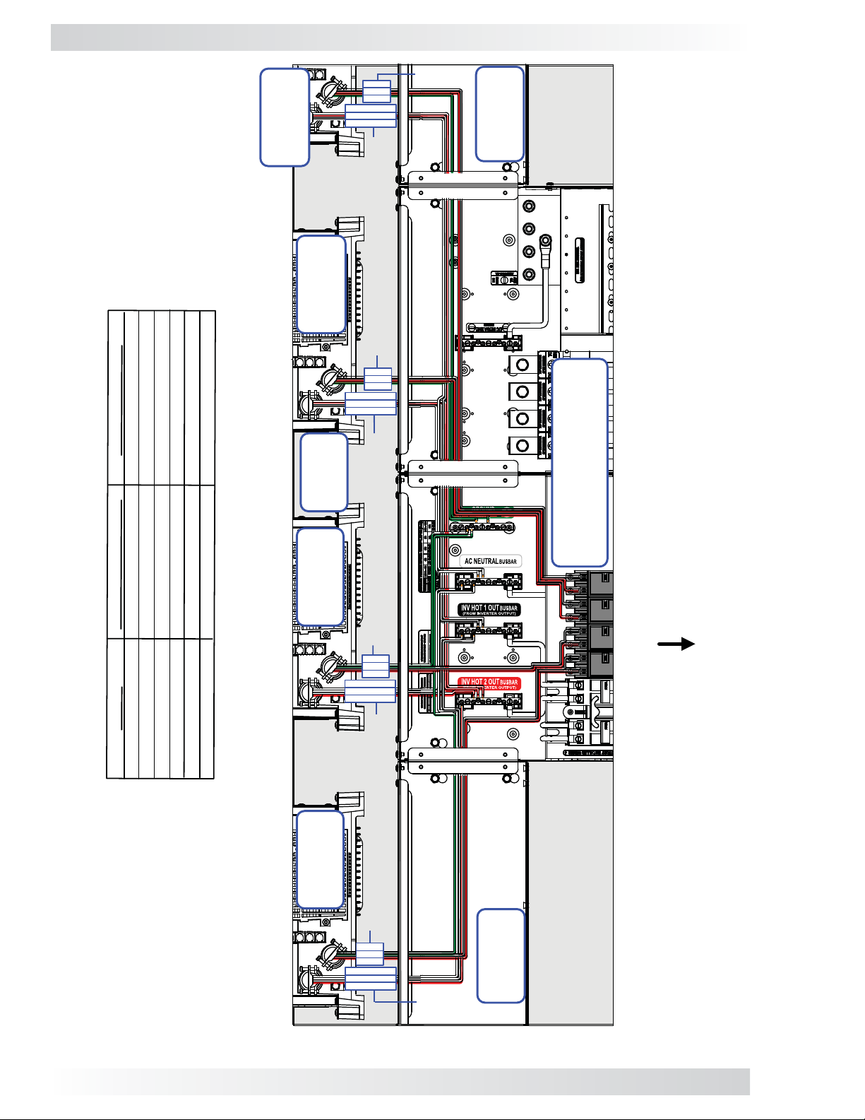
3.0 Installation
(SL3)
Slave 3
(SL2)
Slave 2
Black
Red
Green
Red w/ Stripe
Black w/ Stripe
White
AC OUTPUT
AC INPUT
(to Slave 3)
(from Slave 3)
30D-R
MPXD-
:
TO MPDH-30D
AC NEUTRAL busbar
INV HOT 2 OUT busbar
INV HOT 1 OUT busbar
GROUND busbar
AC INPUT breaker
AC INPUT breaker
:
AC INPUT
AC INPUT
AC OUTPUT
AC OUTPUT
AC OUTPUT
AC INPUT
FROM INVERTER
WIRE
RED
BLACK
WHITE
GREEN
Black
Red
Green
Red w/ Stripe
Black w/ Stripe
White
Series
MS-PAE
Inverters
(SL1)
Slave 1
Green
Black
Red
White
Black w/ Stripe
Red w/ Stripe
AC INPUT
(to Slave 2)
AC OUTPUT
(from Slave 2)
AC INPUT
(to Slave 1)
AC Side/DC Side
MPDH-30D Enclosure
SL3
MA SL1 SL2
RED w/STRIPE
BLACK w/STRIPE
AC OUTPUT
(from Slave 1)
See Figure 3-22a.2 for a closeup
(MA)
MASTER
AC INPUT
(to Master)
Green
Black
Red
White
Black w/ Stripe
Red w/ Stripe
AC
(from
Master)
OUTPUT
Figure 3-22a.1, MPXD-30D / MPDH-30D Inverter AC Wiring
46
© 2011 Magnum Energy, Inc.
30D-L
MPXD-
Page 51

1
234
3.0 Installation
7
8
9
10
11
12
5
6
1 – White 7 – Green
2 – White 8 – Green
3 – Black w/stripe 9 – Red
4 – Black w/stripe 10 – Black
5 – Red w/stripe 11 – Red
6 – Red w/stripe 12 – Black
Green
Black
Red
White
Black w/stripe
Red w/stripe
SL3
SL2
SL1
MA
White
Green
Black w/stripe
Red
Black
Red w/stripe
Figure 3-22a.2, MPXD-30D / MPDH-30D Inverter AC Wiring (Closeup)
© 2011 Magnum Energy, Inc.
47
Page 52

3.0 Installation
MPDH-30D
Enclosure
(AC side)
MA SL1
.Black
.Red
.Red
SL2 SL3
.Black
.Red
.Black
Red
.Red
.Black
Black
.Black
.Red
.Black
.White
.Green
.Green
.White
.Red
LEG
120V
LEG
2
IN
OFF
OFF
OFF
OFF
NEU
1
IN
OFF
OFF
ON
ON
ON
ON
ON
ON
ON
ON
GND
IN
ON
ON
OFF
OFF
OFF
OFF
AC Main Panel
(AC Source)
AC Sub-Panel
GND
(Inverter Loads)
240V
120V
NEU
OUT
O
FF
O
FF
O
FF
O
FF
O
FF
O
FF
LEG
OUT
ON
OFF
OFF
ON
ON
ON
ON
ON
ON
ON
ON
ON
ON
ON
ON
LEG
2
1
OUT
OFF
OFF
OFF
OFF
OFF
OFF
Figure 3-22b, MPXD-30D / MPDH-30D External AC Wiring
48
© 2011 Magnum Energy, Inc.
Page 53

Red cable
to Slave 3
positive DC
terminal
Black cable
Black
Black
to Slave 3
negative
DC
terminal
3.0 Installation
(SL2)
Slave 2
terminal
positive DC
Red cable to
terminal
negative DC
Black cable to
DC Equipment
Ground Terminal
Black
Black
Red
Red
Red
Red
(DC side)
MPDH-30D
SL3
SL2
SL1
MA
Series
MS-PAE
Inverters
terminal
positive DC
Red cable to
(SL1)
Slave 1
terminal
negative DC
Black cable to
Redcable
to Master
positive
DC
terminal
Black
cable to
Master
negative
DC
terminal
BTS ext.
connects
to
Master’s
BTS port
Figure 3-22c, MPXD-30D / MPDH-30D Inverter DC Wiring
© 2011 Magnum Energy, Inc.
(AC side)
MPDH-30D
49
Page 54

3.0 Installation
Connected to each inverter’s
DC Equipment Ground Terminal
(see also Figure 3-22c)
MA
Red
SL1 SL2 SL3
Red
Red
Red
MA
Black
MPDH-30D
Enclosure
SL1
Black
SL2
Black
SL3
Black
Positive (x4),
negative (x4), and
ground (x1) cables
connected to
inverter battery bank
BTS extension
(330V) cable
Connected to
DC System
Ground
Battery
Temperature
Sensor
Figure 3-22d, MPXD-30D / MPDH-3D Battery Bank DC Wiring
50
© 2011 Magnum Energy, Inc.
Page 55

.To Router’s:
.To Router’s:
3.0 Installation
R
D
3
t
t
r
r
o
o
P
P
k
m
c
a
m
t
o
S
C
3
4
L
P
S
.
.
t
t
r
r
o
o
P
P
k
m
c
a
m
t
o
S
C
2
3
L
P
S
.
.
)
3
e
L
v
a
S
l
(
S
2
)
e
2
L
v
a
S
l
(
S
0
3
D
X
P
M
S
T
B
t
r
o
P
k
c
a
t
S
1
L
.To Router’s:
S
.
t
r
o
P
k
c
a
t
S
A
.To Router’s:
M
.
(300V) to BTS
Extension Cable
1
)
e
t
r
o
P
m
m
o
C
2
P
.
1
L
v
a
S
l
(
S
.MS-PAE .MS-PAE .MS-PAE
D
0
3
H
D
P
M
Ports
Comm
inverter
To Slave 3
s
e
l
R
)
t
r
o
P
m
m
o
C
1
P
.
E
T
S
A
M
.MS-PAE
A
M
(
Remote Cable
(300V)
L
D
0
3
-
r
e
t
u
o
R
b
a
C
g
n
i
k
t
c
a
S
D
)
S
T
V
0
B
0
o
3
T
(
.
X
P
M
Stacking
Ports
MA
SL1
SL2
b
a
C
e
t
o
m
e
R
s
e
l
SL3
P2 P3 P4
P1
inverter
To Slave 2
inverter
To Slave 1
inverter
.To Master
Figure 3-22e, MPXD-30D / MPDH-30D Communication Wiring
© 2011 Magnum Energy, Inc.
51
Page 56
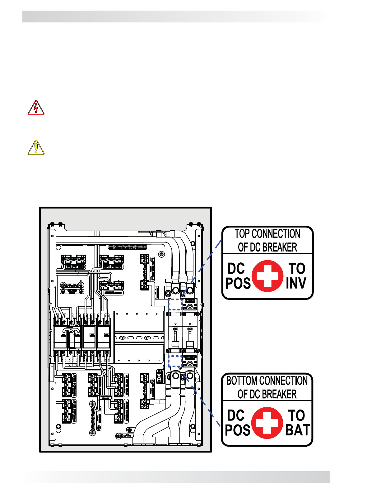
3.0 Installation
3.3 Installation Checklist
After all electrical connections from the MP enclosure to the inverters, batteries, AC source, and subpanel have been completed, refer to the installation checklist in Section 3.13 of your MP Enclosure
Owner’s Manual (PN: 64-0028) to confi rm proper installation.
3.4 Functional Test
Once you confi rm that the system has been installed properly, you are ready to perform a functional
test. Refer to the functional test procedure in Section 3.14 of your MP Enclosure Owner’s Manual.
WARNING: During the functional test – because the front cover has been removed —
you are exposed to potential dangerous voltages and shock hazards inside the MP enclosure that may cause damage, injury , or death. If y ou do not have experience working
with AC and DC voltage circuits, do not attempt this test – use an experienced electrical
installer.
CAUTION: During the functional test, if any step cannot be verifi ed or is incorrect, stop
and recheck/correct the connections before proceeding to the next step.
3.5 Attaching Labels and Covers
The MPX kit has labels for the DC breaker’s positive cable connections (see Figure 2-2). The “Top
Connection of DC Breaker” label affi xes to the top of the new DC breaker. The “Bottom Connection
of DC Breaker” label affi xes to the bottom of the new DC breaker. Refer to Figure 3-23 for proper
placement of both labels.
Figure 3-23, Attaching the Interior DC Labels
52
© 2011 Magnum Energy, Inc.
Page 57

3.0 Installation
Attaching Covers
MP Enclosure - Use the supplied screws and washers to secure the MP enclosure’s cover
(see Figure 3-24).
NOTE: Use #10-32 Star washers (x8),
and #10-32 x
screws (x8)
⅜” T25 Torx Drive
Figure 3-24, Attaching the MP Enclosure Cover
© 2011 Magnum Energy, Inc.
53
Page 58

3.0 Installation
MPX - Use the front cover screws and washers that you removed earlier (Section 3.1.1) to reattach
the MPX extension’s cover (see Figure 3-25).
NOTE: Use the #10-32 Star
washers (x4) and #10-32 x 3/8”
T25 Torx Drive screws (x4) you
removed in Section 3.1.1
Figure 3-25, Attaching the MPX Cover
54
© 2011 Magnum Energy, Inc.
Page 59

3.0 Installation
Router - Use the supplied screws and washers (x2) to secure the router’s cover (see Figure 3-26).
NOTE: Use the supplied
#8 x 3/4" Phillips drive flat
head screws (x2) to
secure the router cover
Figure 3-26, Attaching the Router Cover
© 2011 Magnum Energy, Inc.
55
Page 60

3.0 Installation
SLAVE 1
INVERTER
MASTER
INVERTER
INVERTER DC
DISCONNECT
SWITCH ON
TO INVERT
SLAVE 1
INVERTER
MASTER
INVERTER
INVERTER
AC INPUT
SWITCH ON
TO CHARGE /
P
ASS-THRU
MASTER
INVERTER
SLAVE 1
INVERTER
Figure 3-27, Attaching the Exterior Labels MPSL/MPSH
56
© 2011 Magnum Energy, Inc.
Page 61

KEY
MASTER
A -
SLAVE 1
INVERTER
INVERTER
B -
SLAVE 2
C -
SLAVE 3
INVERTER
D -
D
INVERTER
E -
SWITCH ON
AC INPUT
INVERTER
C
TO CHARGE /
B
ASS-THRU
P
3.0 Installation
TO INVERT
SWITCH ON
DISCONNECT
INVERTER DC
F -
D
F
C
F
B
A
D
E
C
E
B
A
A
Figure 3-28, Attaching the Exterior Labels MPDH
© 2011 Magnum Energy, Inc.
57
Page 62

4.0 Warranty and Service Information
4.0 Warranty and Service Information
4.1 Limited Warranty
Magnum Energy, Inc., warrants the MPX Extension Kit to be free from defects in material and
workmanship that result in product failure during normal usage, according to the following terms
and conditions:
1. The limited warranty for the product extends for 12 months beginning from the product’s
original date of purchase.
2. The limited warranty extends to the original purchaser of the product and is not assignable or
transferable to any subsequent purchaser.
3. During the limited warranty period, Magnum Energy will repair, or replace at Magnum Energy’s
option, any defective parts, or any parts that will not properly operate for their intended use
with factory new or remanufactured replacement items if such repair or replacement is needed
because of product malfunction or failure during normal usage. The limited warranty does not
cover defects in appearance, cosmetic, decorative or structur al parts or any non-operative parts.
Magnum Energy’s limit of liability under the limited warranty shall be the actual cash value of
the product at the time the original purchaser returns the product for repair, determined by the
price paid by the original purchaser. Magnum Energy shall not be liable for any other losses or
damages.
4. Upon request from Magnum Energy, the original purchaser must prove the product’s original
date of purchase by a dated bill of sale, itemized receipt.
5. The original purchaser shall return the product prepaid to Magnum Energy in Everett, WA. After
the completion of service under this limited warranty, Magnum Energy will return the product
prepaid to the original purchaser via a Magnum-selected non-expedited surface freight within
the contiguous United States and Canada; this excludes Alaska and Hawaii.
6. This limited warranty is voided if:
• the product has been modifi ed without authorization
• the serial number has been altered or removed
• the product has been damaged from abuse, neglect, accident, high voltage or corrosion
• the product was not installed and operated according to the owner's manual
4.2 How to Receive Repair Service
If your product requires warranty service or repair, contact either:
1. An Authorized Service Center, which are listed on the Magnum Energy website at
www.magnumenergy.com/servicecenters.htm; or
2. Magnum Energy, Inc. at:
Telephone: 425-353-8833
Fax: 425-353-8390
Email: warranty@magnumenergy.com
If returning the product directly to Magnum Energy for repair, you must:
• return the unit in the original, or equivalent, shipping container
• ensure the product is properly packaged, any damage due to inadequate packaging
is not covered under warranty
• receive a Return Materials Authorization (RMA) number from the factory prior to the
return of the product to Magnum Energy for repair
• place RMA numbers clearly on the shipping container or on the packing slip
BEFORE RETURNING ANY UNIT TO MAGNUM ENERGY INC.,
A RETURN MATERIAL AUTHORIZATION (RMA) NUMBER IS REQUIRED.
58
© 2011 Magnum Energy, Inc.
Page 63

Magnum Energy, Inc.
2211 West Casino Rd.
Everett, WA 98204
Phone: 425-353-8833
Fax: 425-353-8390
Web: www.magnumenergy.com
MPX Owner’s Manual (PN: 64-0051 Rev A)
 Loading...