

Page 1

Magnum Panels (MP) AC/DC Distribution Enclosures
Owner’s Manual
Page 2

Disclaimer of Liability
The
use of this manual and the conditions or methods of installation, operation, use and maintenance
of the Magnum Panel is beyond the control of Magnum Energy, Inc. Therefore, this company does
not assume responsibility and expressly disclaims liability for loss, damage, or expense, whether
direct, indirect, consequential or incidental, arising out of or anyway connected with such installation,
operation, use, or maintenance.
Note as well that while every precaution has been taken to ensure the accuracy of the contents
of this manual, the specifi cations and product functionality may change without notice. Magnum
Energy, Inc. assumes no responsibility for errors or omissions.
Restrictions on Use
Magnum Energy, Inc. does not recommend the use of any o
life saving, or other medical equipment or devices designated as “critical” by the U.S. FDA where
failure or malfunction of the Magnum Energy product can be reasonably expected to cause failure
of the life support device, or to signifi cantly affect its safety or effectiveness. Using Magnum Energy
products with this particular equipment is at your own risk.
f its products with life support systems,
Copyright Notice
Copyright © 2011 by Magnum Energy, Inc. All rights reserved. Permission to copy, distribute and/
or m
odify this document is prohibited unless express written permission from Magnum Energy, Inc.
is provided.
Contact Information
Magnum Energy, Inc.
2211 West Casino Rd.
Everett, WA 98204
Phone: 425-353-8833
F
ax: 425-353-8390
Web: www.MagnumEnergy.com
Statement of Appreciation
From all of us at Magnum Energy -
Thank you for purchasing this Magnum Panel (MP).
We
understand that you have many purchasing options in the marketplace, and are pleased that you
have decided on a Magnum Energy product. This MP enclosure was proudly designed, assembled
and tested in the United States at our Everett, Washington facility.
At Magnum, we are committed to providing you with quality products and services; we hope that
your experience with us is pleasant and professional.
Page i
Magnum Energy® is a registered trademark of Magnum Energy, Inc.
© 2010 Magnum Energy, Inc.
Page 3

Table of Contents
1.0 Safety Information
1.1 Safety Symbols .................................................................................... v
1.2 General Safety ..................................................................................... v
1.3 Battery Safety ......................................................................................vi
................................................................... v
2.0 Introduction ............................................................................. 1
2.1 MP Series Overview .............................................................................. 1
2.2 Regulatory Compliance .......................................................................... 6
2.3 MP External Components ....................................................................... 7
2.4 MP Internal Components ........................................................................ 9
3.0 Installation ............................................................................ 17
3.1 Pre-Installation ................................................................................... 17
3.2 Location ............................................................................................ 22
3.3 Preparing the MP Enclosure and Inverter ................................................ 25
3.4 Mounting the MP/Inverter System ......................................................... 31
3.5 Wiring the MP Enclosures ..................................................................... 36
3.6 AC Wiring .......................................................................................... 38
3.7 DC Wiring .......................................................................................... 44
3.8 Wiring Accessories .............................................................................. 51
3.9 Removing the NEUTRAL-GROUND Wire .................................................. 53
3.10 Removing the NEGATIVE-GROUND Busbar ............................................. 54
3.11 MP/Inverter System Grounding ............................................................. 55
3.12 Installation Checklist ........................................................................... 59
3.13 Functional Test ................................................................................... 61
3.14 Attaching Front Covers ........................................................................ 66
3.15 Master/Slave Identifi cation Label Set ..................................................... 67
4.0 Wiring Diagrams .................................................................... 68
5.0 Operation ............................................................................... 93
5.1 Inverter DC Disconnect Breaker ............................................................ 94
5.2 Inverter AC Input Breaker .................................................................... 94
5.3 Bypass Switch Assembly ...................................................................... 94
Appendix A - Misc. Info and Optional Equipment/Accessories ........ 97
A1 Installing the Charge Controller Bracket ................................................. 97
A2 Installing a Battery Monitor .................................................................100
A3 Inverter Hood Info .............................................................................102
A4 Router Bracket Info ...........................................................................102
A5 Knockout Plate ..................................................................................104
A6 Installing Optional DC Breakers ...........................................................105
A7 Installing Optional AC Load Breakers ....................................................107
A8 Aligning Front Breaker Face Plate .........................................................108
A9 Optional Router Front Top Cover ..........................................................109
A10 Installing Lightning Arrestors ...............................................................110
Appendix B - Warranty and Service .............................................. 112
B1 Limited Warranty ...............................................................................112
B2 How to Receive Repair Service .............................................................112
© 2010 Magnum Energy, Inc.
Page ii
Page 4

List of Figures
Figure 2-1a, MPSL-30D as Shipped ................................................................................................
Figure 2-1b, MPSL-30D with Field Installed Options ..........................................................................2
Figure 2-2a, MPSL-60S as Shipped .................................................................................................3
Figure 2-2b, MPSL-60S with Field Installed Options ..........................................................................3
Figure 2-3a, MPSH-30D as Shipped ................................................................................................4
Figure 2-3b, MPSH-30D with Field Installed Options .........................................................................4
Figure 2-4a, MPDH-30D as Shipped ...............................................................................................5
Figure 2-4b, MPDH-30D with Field Installed Options .........................................................................5
Figure 2-5, MPSL and MPSH External Components ...........................................................................7
Figure 2-6, MPDH External Components .........................................................................................8
Figure 2-7, MPSL-30D Internal Components .................................................................................. 12
Figure 2-8, MPSL-60S Internal Components .................................................................................. 13
Figure 2-9, MPSH-30D Internal Components ................................................................................. 14
Figure 2-10a, MPDH-30D (AC Side) Internal Components ............................................................... 15
Figure 2-10b, MPDH-30D (DC Side) Internal Components ............................................................... 16
Figure 3-1, Parts Included - MPSL and MPSH Models ...................................................................... 18
Figure 3-2, Parts Included - MPDH Models ..................................................................................... 18
Figure 3-3, MP Series Simplifi ed Parallel-Stacked Installation Diagram .............................................. 20
Figure 3-4, MP Series Simplifi ed Series-Stacked Installation Diagram ............................................... 21
Figure 3-5, System Dimensions (Single Enclosure) ......................................................................... 23
Figure 3-6, System Dimensions (Dual Enclosure) ........................................................................... 24
Figure 3-7, Front Cover Screws to Remove .................................................................................... 25
Figure 3-8, Removing Front Cover - Single Enclosure...................................................................... 26
Figure 3-9, Removing Front Covers - Dual Enclosure ...................................................................... 26
Figure 3-10, Conduit/Wire Routing ............................................................................................... 27
Figure 3-11, Removing Knockouts ................................................................................................ 28
Figure 3-12, Connect and Separate Inverter AC Wires .................................................................... 28
Figure 3-13, MPSL/MPSH Dimensions and Knockout Location/Sizes .................................................. 29
Figure 3-14, MPDH Dimensions and Knockout Location/Sizes ........................................................... 30
Figure 3-15a, Mounting the MP Single Enclosure ............................................................................ 31
Figure 3-15b, Mounting Inverter - MP Single Enclosure ................................................................... 32
Figure 3-15c, Mounting Inverter Hood - MP Single Enclosure ........................................................... 32
Figure 3-16a, Mounting the MP Dual Enclosure (DC Side) ................................................................ 33
Figure 3-16b, Mounting the MP Dual Enclosure (AC Side) ................................................................ 33
Figure 3-16c, Connecting the Two Sides Together - MP Dual Enclosure .............................................. 34
Figure 3-16d, Mounting First Inverter - MP Dual Enclosure .............................................................. 34
Figure 3-16e, Mounting Second Inverter - MP Dual Enclosure .......................................................... 35
Figure 3-16f, Mounting the Inverter Hoods - MP Dual Enclosure ....................................................... 35
Figure 3-17, MPSL-30D and MPSH-30D AC Wiring Connections ........................................................ 41
Figure 3-18, MPSL-60S AC Wiring Connections .............................................................................. 42
Figure 3-19, MPDH-30D AC Wiring Connections ............................................................................. 43
Figure 3-20, DC Hardware Connections ........................................................................................ 46
Figure 3-21, DC Wiring Connection Points for MPSL Models ............................................................. 48
Figure 3-22, DC Wiring Connection Points for MPSH-30D ................................................................. 49
Figure 3-23, DC Wiring Connection Points for MPDH-30D (DC Side) .................................................. 50
Figure 3-24, REMOTE Communication Cable (300V Rated) .............................................................. 51
Figure 3-25, NETWORK Communication Cable (300V Rated) ............................................................. 51
Figure 3-26, Extension Cable (300V Rated) .................................................................................... 51
Figure 3-27, Accessory Wiring Using 300 Volt Communications Cables .............................................. 52
Figure 3-28, Removing the NEUTRAL-GROUND Wire ....................................................................... 53
Figure 3-29, Removing the NEGATIVE-GROUND Busbar .................................................................. 54
Figure 3-30, Grounding System for Inverter with MP Enclosure ........................................................ 55
Figure 3-31, Single Connection to DC Ground Rod (Method 1) ......................................................... 56
Figure 3-32, Multiple Connections to DC Ground Rod (Method 2) ...................................................... 57
Figure
3-33, Multiple Connections to DC Ground Rod (Method 3) ...................................................... 57
Figure 3-34, DC V
Figure 3-35, DC V
Figure 3-36, AC Voltage Checks - MPSL-30D and MPSH-30D Models ................................................. 63
Figure 3-37, AC Voltage Checks - MPSL-60S Models ....................................................................... 64
Figure 3-38, AC Voltage Checks - MPDH-30D (AC Side) Models ........................................................ 65
Figure 3-39, Attaching Front Cover - MPSL/MPSH Models ................................................................ 66
oltage Checks - Single Enclosures
oltage Checks - Dual Enclosures (DC Side) ........................................................... 61
.......................................................................
61
2
Page iii
© 2010 Magnum Energy, Inc.
Page 5

Figure 3-40, Attaching Front Covers - MPDH Models ....................................................................... 66
Figure 3-41, Applying Master/Slave Identifi cation Labels ................................................................. 67
Figure 4-1, Inverter AC Input and Output Wiring Diagram - MS4024................................................. 69
Figure 4-2, Inverter AC Input and Output Wiring Diagram - MS-PAE Series ........................................ 70
Figure 4-3a, MPSL-30D Inverter AC Wiring .................................................................................... 71
Figure 4-3b, MPSL-30D External AC Wiring .................................................................................... 72
Figure 4-3c, MPSL-30D DC Wiring ................................................................................................ 73
Figure 4-3d, MPSL-30D Communications Wiring ............................................................................. 74
Figure 4-3e, MPSL-30D Full System Wiring Diagram ....................................................................... 75
Figure 4-4a, MPSL-60S Inverter AC Wiring .................................................................................... 76
Figure 4-4b, MPSL-60S External AC Wiring .................................................................................... 77
Figure 4-4c, MPSL-60S DC Wiring ................................................................................................ 78
Figure 4-4d, MPSL-60S Communications Wiring ............................................................................. 79
Figure 4-4e, MPSL-60S Full System Wiring Diagram ....................................................................... 80
Figure 4-5a, MPSH-30D Inverter AC Wiring ................................................................................... 81
Figure 4-5b, MPSH-30D External AC Wiring ................................................................................... 82
Figure 4-5c, MPSH-30D DC Wiring ............................................................................................... 83
Figure 4-5d, MPSH-30D Communications Wiring ............................................................................ 84
Figure 4-5e, MPSH-30D Full System Wiring Diagram ...................................................................... 85
Figure 4-6a, MPDH-30D Inverter AC Wiring ................................................................................... 86
Figure 4-6b, MPDH-30D External AC Wiring ................................................................................... 87
Figure 4-6c, MPDH-30D Inverter DC Wiring ................................................................................... 88
Figure 4-6d, MPDH-30D External DC Wiring .................................................................................. 89
Figure 4-6e, MPDH-30D Communications Wiring ............................................................................ 90
Figure 4-6f.1, MPDH-30D Full System Wiring Diagram (AC Side) ...................................................... 91
Figure 4-6f.2, MPDH-30D Full System Wiring Diagram (DC Side) ...................................................... 92
Figure 5-1, MP Functional Diagram............................................................................................... 93
Figure 5-2, 60A Bypass Switch Operation (MPSL-30D and MPSL-60S) ............................................... 95
Figure 5-3, 125A Bypass Switch Operation (MPSH-30D and MPDH-30D) ............................................ 96
Figure A1-1, Charge Controller Bracket - Physical Dimensions.......................................................... 97
Figure A1-2, Charge Controller Bracket Mounting Holes .................................................................. 98
Figure A1-3, Holes Used to Mount Bracket on MP Enclosure ............................................................. 99
Figure A2-1, Accessing the DC Shunt .......................................................................................... 100
Figure A2-2, Wiring the ME-BMK-NS ............................................................................................ 100
Figure A2-3, Mounting the Sense Module ..................................................................................... 101
Figure A2-4, Close-up of Wiring the Sense Module and DC Shunt .................................................... 101
Figure A3-1, Inverter Hood Dimensions ....................................................................................... 102
Figure A4-1, Router Bracket Dimensions ...................................................................................... 102
Figure A4-2, Router Bracket Kit .................................................................................................. 103
Figure A4-3, Mounting the Router Bracket and Router.................................................................... 103
Figure A5-1, Attaching Knockout Plate ......................................................................................... 104
Figure A5-2, Knockout Plate Dimensions and Knockouts ................................................................. 104
Figure A6-1, Installing DIN Rail-Mounted DC Breakers ................................................................... 105
Figure A6-2, Installing Back-Mounted DC Breakers ........................................................................ 106
Figure A6-3, Wiring DC Breakers to Controller/PV Array ................................................................. 106
Figure A7-1, Installing AC Load Breakers - Single MP Enclosure ...................................................... 107
Figure A7-2, Installing AC Load Breakers - Dual MP Enclosure ........................................................ 107
Figure A8-1, Removing the Front Breaker Face Plate ..................................................................... 108
Figure A9-1, Router Front Top Cover ........................................................................................... 109
Figure A10-1, Installing Lightning Arrestor on MP Enclosure ........................................................... 110
Figure A10-2, Wiring Lightning Arrestor to MP Enclosure ................................................................ 111
List of Tables
Table 3-1, T
Table 3-2, Torque Values for 3/8-16 Bolts ..................................................................................... 37
Table 3-3, Torque Values for Terminal Screws on AC Input Breakers ................................................. 37
Table 3-4, MP AC Wire Kits .......................................................................................................... 39
Table 3-5, Minimum AC Wire Size for AC Output Breaker ................................................................. 40
Table 3-6, AC Grounding Electrode Conductor Sizing ...................................................................... 56
Table 3-7, Equipment Grounding Conductor Sizing ......................................................................... 58
Table 4-1, MP Wiring Diagrams .................................................................................................... 68
Table A-1, Mounting Holes Used for Charge Controllers ................................................................... 97
© 2010 Magnum Energy, Inc.
orque Values for Dual Hole Busbars ............................................................................. 37
Page iv
Page 6

1.0 Safety Information
1.0 Safety Information
IMPORTANT SAFETY INSTRUCTIONS
his manual contains important safety instructions that
T
and operation of this product. Before using the Magnum Panel (MP), read all instructions
and cautionary markings on: (1) the MP enclosure, (2) the inverter/charger, and (3) the
batteries, as well as the individual manuals provided for each component of the system.
These installation instructions are for use by qualifi ed personnel only. Do not perform any
installation or servicing other than that specifi ed in this owner’s manual unless qualifi ed to do so.
Incorrect installation or servicing may result in a risk of electric shock, fi re, or other safety hazard.
must be followed during the installation
1.1 Safety Symbols
The following safety symbols have been placed throughout this manual to indicate dangerous
conditions and important safety instructions.
WARNING: This symbol
physical harm to the user.
CAUTION: This symbol indicates that failure to take a specifi ed action could result in
damage to the equipment.
Info: This symbol indicates information that emphasizes or supplements important
points of the main text.
indicates that failure to take a specifi ed action could result in
1.2 General Safety
• All electrical work must be performed in accordance with local and national electrical codes.
This product is designed for indoor/compartment installation. It must not be exposed to rain,
•
snow, moisture or liquids of any type.
• Use insulated tools to reduce the chance of electrical shock or accidental short circuits.
• Remove all jewelry such as rings, watches, bracelets, etc., when installing or performing
maintenance on the inverter.
• Both AC and DC overcurrent protection must be provided as part of the installation.
• Use Class 1 wiring methods for fi eld wiring connections to terminals of a Class 2 circuit.
• Listed or labeled equipment shall be installed and used in accordance with any instructions
included in the listing or labeling.
• To reduce risk of electric shock, disconnect all wiring before attempting any maintenance or
cleaning. Turning off the inverter will not reduce this risk, the inverter bypass must be used or
the panel should be totally disconnected from all sources.
• All wiring must have a minimum rating of 150V, 75°C when using 120V AC inverters; or 300V,
75°C when using 120/240V AC inverters.
• AC wiring must be no less than 10 AWG (5.3 mm2) gauge copper wire.
• Battery cables should be no less than #4/0 AWG unless fused close to the battery bank for
smaller sized cables.
• Crimped and sealed copper ring terminal lugs with a 3/8” hole should be used to connect to
the DC terminals inside the MP enclosure. Soldered cable lugs are also acceptable.
• Torque all AC wiring connections and DC cable connections to the required torque values.
READ AND SAVE THESE INSTRUCTIONS
© 2011 Magnum Energy, Inc.Page v
Page 7

1.0 Safety Information
1.3
Battery Safety
IMPORTANT BATTERY SAFETY INSTRUCTIONS
• Be very careful when working around batteries, they can produce extremely high currents if
short-circuited. Read
inverter and batteries.
• Wear eye protection such as safety glasses when working with batteries.
• Remove all jewelry such as rings, watches, bracelets, etc., when installing or performing
maintenance on the batteries.
• Never work alone. Always have someone near you when working around batteries.
• Use proper lifting techniques when working with batteries.
• Never use old or untested batteries. Check each battery’s label for age, type, and date code
to ensure all batteries are identical.
• Batteries are sensitive to changes in temperature. Always install batteries in a stable
environment.
• Install batteries in a well ventilated area. Batteries can produce explosive gasses. For
compartment or enclosure installations, always vent batteries to the outside.
• Provide at least one inch of air space between batteries to provide optimum cooling.
• Never smoke when in the vicinity of batteries.
• To prevent a spark at the battery and reduce the chance of explosion, always connect the
cables to the batteries fi rst. Then connect the cables to the MP enclosure/inverter system.
• Use insulated tools at all times.
• Always verify proper polarity and voltage before connecting the batteries to the MP enclosure/
inverter system.
• To reduce the chance of fi re or explosion, do not allow the battery terminals to be shortcircuited.
• In the event of accidental exposure to battery acid, wash thoroughly with soap and water. In
the event of exposure to the eyes, fl ood them for at least 15 minutes with running water and
seek immediate medical attention.
• Recycle old batteries.
• Be extra cautious to reduce the risk of dropping a metal tool onto batteries. It could short-circuit
the batteries or other electrical parts, resulting in sparks that could cause a fi re or an explosion.
the battery supplier’s precautions before installing and connecting the
• Cover the terminals to prevent accidental shorting.
READ AND SAVE THESE INSTRUCTIONS
© 2011 Magnum Energy, Inc.
Page vi
Page 8

2.0 Introduction
2.0 Introduction
The Magnum P
dardize inverter installations and allow for the ability to expand the inverter system in the future.
Specifi cally designed for multiple inverter applications, the MP enclosures ensure safety and reliability by combining all of the major components required for a renewable energy system — inverter/
battery disconnect, AC overcurrent protection, grounding connections, and a full-system bypass
switch — into an easy to install pre-wired enclosure. The modular design of the MP enclosure with
the Magnum Energy inverter allows it to be UPS shipped and easily assembled on site.
Installing an inverter system is now as simple as mounting the MP enclosure, installing the inverters, connecting the battery bank, and if needed, bringing in AC power from a generator or the
utility grid. Now all of the inverter’s required AC and DC disconnects and wire connection points
are all together, and integrated in the self-contained MP enclosure.
anels (MP) are part of a new line of enclosures from Magnum Energy that stan-
2.1 MP Series Overview
The MP enclosures are available in four basic confi gurations: the MPSL-30D, MPSH-30D, and
MPDH-30D are designed to be used with the Magnum MS-PAE inverter models when stacked in
parallel; and the MPSL-60S, which is designed for use with two MS4024 inverters when stacked
in series. These confi gurations provide different maximum power abilities to meet present and
future requirements.
2.1.1 Models
MPSL-30D (Magnum Panel,
MPSL-60S (Magnum Panel, Single Enclosure, Low Capacity, Single-pole 60A AC input breaker)
MPSH-30D (Magnum Panel, Single Enclosure, High Capacity, Double-pole 30A AC input breakers)
MPDH-30D (Magnum Panel, Dual Enclosure, High Capacity, Double-pole 30A AC input breakers)
Single Enclosure, Low Capacity, Double-pole 30A AC input breakers)
2.1.2 Standard Features
The main components and features for the MP Series enclosures are:
• Standard confi gur
• Enclosure is steel construction with a durable, white powder coat fi nish to help prevent corrosion
• Built-in, pre-wired, full system bypass switch for inverter isolation/battery maintenance
• Front-mounted AC and DC breakers for quick and easy operation
• AC, DC, and Ground busbars with set-screw type compression terminals (no lugs required)
• Full system capacity shunt (500 or 1000 DCA), allows easy connection to battery monitor
• Enclosure and components are certifi ed for indoor use to UL/CSA standards
• DC negative and ground busbars (negative can be isolated if PV-GFP device installed)
• Battery positive busbar for DC loads and PV arrays included (not available on MPSH-30D)
• Space available to add DC load/disconnect breakers (not available on MPSH-30D)
• Standalone top plate provided to allow other (non-Magnum) inverter installations
• Knockouts for inverter and battery cables, PV in/out, DC breakers
• Data cables with 300-volt rated insulation provided to allow 240V AC inverter installations
• Easy accessibility for fi eld installation/wiring of additional breakers/components
• Pre-wired AC over-current circuit breaker protection to the inverter’s input
• Space for additional AC breakers (depends on enclosure confi guration)
• Inverter DC disconnect with inverter-to-breaker battery cables included
• Plated copper busbars included for up to six additional battery positive and negative circuits
ations allow future expansion using MPX enclosures for increased power
© 2011 Magnum Energy, Inc.Page 1
Page 9
2.0 Introduction
MPSL-30D
MPXS-30D-L
MS-PAE
I
NVERTER
MPSL-30D
BP-D
ME-RTR
MS-PAE
I
NVERTER
MPXS-30D-L
MPSL-30D
MPXS-30D-R
MPSL-30D
MPXS-30D-R
MS-PAE
I
NVERTER
BP-D
ME-RTR
MS-PAE
INVERTER
MPSL-30D
2.1.3 Individual Features
MPS
L-30D (Magnum Panel, Single Enclosure, Low Capacity, Double 30A AC Inverter Input Breaker)
Capability for one MS-PAE Series inverter (expandable to a maximum of two MS-PAE Series
inverters stacked in parallel using an optional MPX extension box).
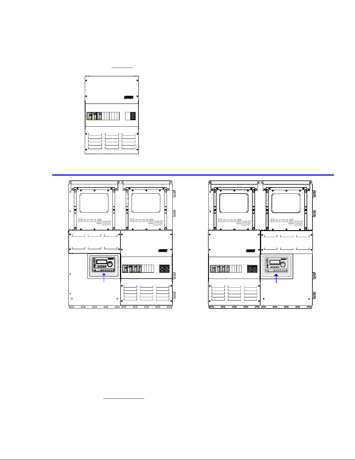
MPSL-30D (as shipped)
Includes:
• D
30A AC Inverter Input
Breaker (x1)
• 250A DC Disconnect
(x1)
• Inverter AC Input/
Output wires
• Data cables rated for
120/240V AC circuits
Figure 2-1a, MPSL-30D as Shipped
• D60A AC System
Bypass
• 500A/50mV DC
Shunt
• Inverter Hood (x1)
• Router Bracket
MPSL-30D
with MPXS-30D-L
Includes:
30A AC Inverter Input Breakers (x2) • D60A AC System Bypass
• D
• 250A DC Disconnects (x2) • 500A/50mV DC Shunt
• Inverter AC Input/Output wires • Inverter Hoods (x2)
• Data cables rated for 120/240V AC circuits • Router Bracket
Field Installed Options Shown (not included):
• PAE Series parallel-stack inverters (x2) • BP-D Dual Mounting Backplate
• ME-RTR R
outer
(MPX - Left Side)
with MPXS-30D-R (MPX - Right Side)
MPSL-30D
Figure 2-1b, MPSL-30D with Field Installed Options
© 2011 Magnum Energy, Inc.
Page 2
Page 10
2.0 Introduction
MPSL-30D
MPXS-30D-L
MS4024
INVERTER
MPSL-60S
BP-D
MS4024
INVERTER
MPXS-60S-L
ME-ARC
MPSL-30D
MPXS-30D-R
MPSL-60S
MPXS-60S-R
MS4024
I
NVERTER
BP-D
MS4024
I
NVERTER
ME-ARC
MPSL-30D
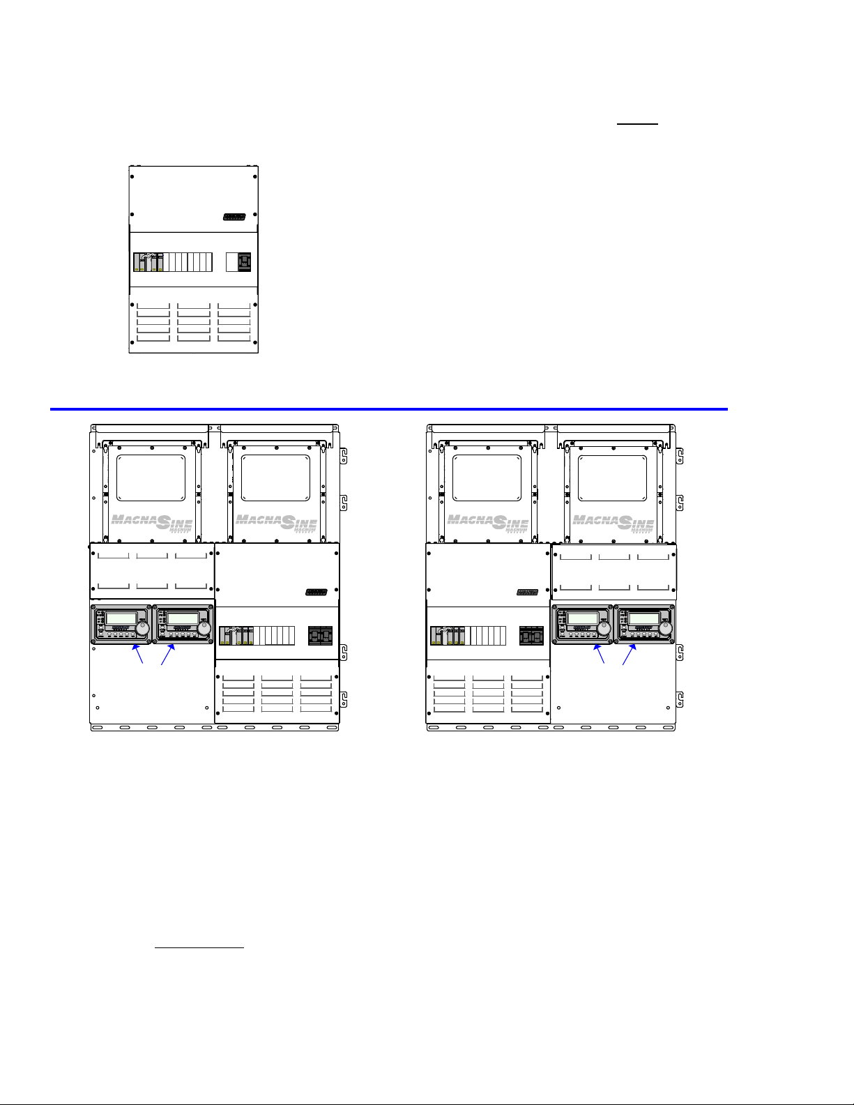
MPSL-60S (Ma
Capability for one MS4024 inverter (expandable to two MS4024’s stacked in series using an
optional MPX extension box)
gnum Panel, Single Enclosure, Low Capacity, Single 60A AC Inverter Input Breaker)
MPSL-60S
Includes:
S60A AC Inverter Input
•
Breaker (x1)
• 250A DC Disconnect
(x1)
• Inverter AC Input/
Output wires
• Data cables rated for
120/240V AC circuits
(as shipped)
• D60A AC System
Bypass
• 500A/50mV DC
Shunt
• Inverter Hood (x1)
• Router and Charge
Controller Bracket
Figure 2-2a, MPSL-60S as Shipped
MPSL-60S
with MPXS-60S-L
Includes:
60A AC Inverter Input Breakers (x2) • D60A AC System Bypass
• S
• 250A DC Disconnects (x2) • 500A/50mV DC Shunt
• Inverter AC Input/Output wires • Inverter Hoods (x2)
• Data cables rated for 120/240V AC circuits • Series Stacking Cable
Field Installed Options Shown (not included):
• MS4024 series-stack inverters (x2) • BP-D Dual Mounting Backplate
• ME-ARC Adv
anced Remotes (x2)
(MPX - Left Side)
Figure 2-2b, MPSL-60S with Field Installed Options
MPSL-60S
with MPXS-60S-R (MPX - Right Side)
© 2011 Magnum Energy, Inc.Page 3
Page 11
2.0 Introduction
MPXS-30D-L
MPXS-30D-R
MPSH-30D
MS-PAE
I
NVERTER
MPXS-30D-L
BP-S
ME-RTR
MS-PAE
I
NVERTER
MPXS-30D-R
BP-D
MPSH-30D
MS-PAE
I
NVERTER
MPSH-30D
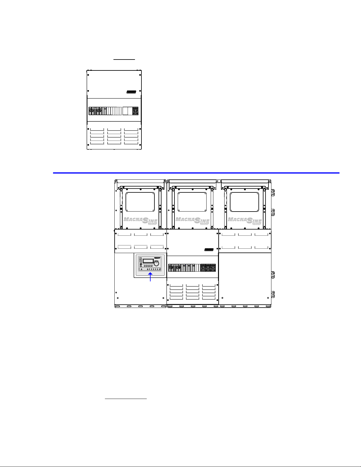
MPSH-30D (M
Capability for one MS-PAE Series inverter (expandable to a maximum of three MS-PAE Series
inverters stacked in parallel using optional MPX extension boxes)
agnum Panel, Single Enclosure, High Capacity, Double 30A AC Inverter Input Breaker)
MPSH-30D (as shipped)
Includes:
• D
30A AC Inverter Input
Breaker (x1)
• 250A DC Disconnect
(x1)
• Inverter AC Input/
Output wires
• Data cables rated for
120/240V AC circuits
• D125A AC System
Bypass
• 1000A/100mV DC
Shunt
• Inverter Hood (x1)
• Router and Charge
Controller Bracket
Figure 2-3a, MPSH-30D as Shipped
MPSH-30D with MPXS-30D-L (MPX - Left Side) and MPSX-30D-R (MPX - Right Side)
Includes:
30A AC Inverter Input Breakers (x3) • D125A AC System Bypass
• D
• 250A DC Disconnects (x3) • 1000A/100mV DC Shunt
• Inverter AC Input/Output wires • Inverter Hoods (x3)
• Data cables rated for 120/240V AC circuits • Router and Controller Bracket
Field Installed Options Shown (not included):
• PAE Series parallel-stack inverters (x3) • BP-S Single Mounting Backplate
• ME-RTR R
outer • BP-D Dual Mounting Backplate
Figure 2-3b, MPSH-30D with Field Installed Options
© 2011 Magnum Energy, Inc.
Page 4
Page 12
2.0 Introduction
MPXD-30D-L
MPXD-30D-R
MPDH-30D
MS-PAE
I
NVERTER
MPXD-30D-L
BP-D
ME-RTR
MS-PAE
I
NVERTER
MS-PAE
I
NVERTER
MS-PAE
I
NVERTER
MPXD-30D-R
BP-D
MPDH-30D
AC Side
DC Side
MPDH-30D
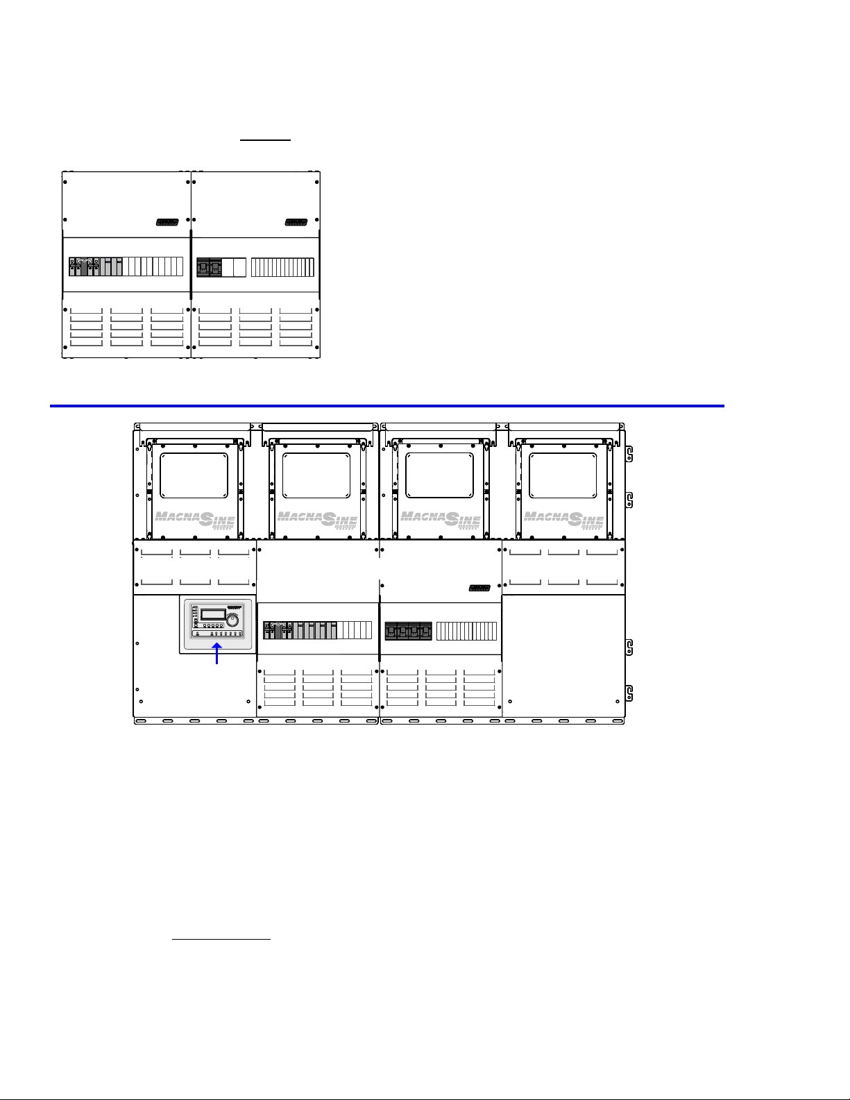
MPDH-30D (M
Capability for one or two MS-PAE Series inverters (expandable to a maximum of four MS-PAE
Series inverters stacked in parallel using optional MPX extensions).
agnum Panel, Dual Enclosure, High Capacity, Double 30A AC Inverter Input Breakers)
MPDH-30D (as shipped)
Includes:
• D
30A AC Inverter Input
Breakers (x2)
• 250A DC Disconnects
(x2)
• Inverter AC Input/
Output wires
• Data cables rated for
120/240V AC circuits
• D125A AC System
Bypass
• 1000A/100mV DC
Shunt
• Inverter Hoods (x2)
• Router and Charge
Controller Bracket
Figure 2-4a, MPDH-30D as Shipped
MPDH-30D with MPXD-30D-L (MPX - Left Side) and MPXD-30D-R (MPX - Right Side)
Includes:
30A AC Inverter Input Breakers (x4) • D125A AC System Bypass
• D
• 250A DC Disconnects (x4) • 1000A/100mV DC Shunt
• Inverter AC Input/Output wires • Inverter Hoods (x4)
• Data cables rated for 120/240V AC circuits • Router and Controller Bracket
Field Installed Options Shown (not included):
• PAE Series parallel-stack inverters (x4) • BP-D Dual Mounting Backplates (x2)
• ME-RTR R
outer
Figure 2-4b, MPDH-30D with Field Installed Options
© 2011 Magnum Energy, Inc.Page 5
Page 13

2.0 Introduction
2.1.4
• MP Dimensions (H x W x D): Each Enclosure = 18” x 13” x 6.75” (45.7cm x 33cm x 17.1cm)
MP Weight:
•
(20 kg), MPDH (D Side) = 46 lbs. (20.7 kg)
• Shipping Dimensions (H x W x D): 26.75” x 17.75” x 14.75” (56.9cm x 38.1cm x 31.8cm)
• Shipping Weight: MPSL = 50 lbs. (22.7 kg), MPSH = 53 lbs. (24 kg), MPDH (AC Side) = 46 lbs.
(20.7 kg), MPDH (D Side) = 48 lbs. (21.8 kg)
Physical Features
MPSL = 48 lbs. (21.8 kg), MPSH = 51 lbs. (23.1 kg), MPDH (AC Side) = 44 lbs.
2.1.5 Optional Accessories/Components
• ME-RC – R
confi gured and monitored, and maintains the critical settings in nonvolatile memory.
• ME-ARC – Advanced Remote Control with LCD display; has all the features of the ME-RC remote,
but also confi gures the advanced features of the inverter (or any connected accessory).
• ME-RTR – The ME-RTR, or “router” provides parallel capability for the MS-PAE Series inverters
and includes many of the same features as the ME-ARC advanced remote control. The router
is designed with a user-friendly LCD display and rotary SELECT knob that allows all connected
MS-PAE series inverter/chargers to be programmed in sync without the need to program
each inverter separately. The router will accommodate up to four MS-PAE inverter/chargers
in parallel, plus accessories.
• ME-BMK-NS – Battery Monitor; determines battery State of Charge (DC shunt not included).
• ME-AGS-N – Automatic Generator Start Controller (Network version); automatically starts/
stops generators.
• BP-S – Single Mounting Backplate; for mounting a Magnum inverter and MP/MPX enclosures.
It can be combined with the BP-D for additional mounting surface area. UPS shippable.
• BP-D – Dual Mounting Backplate; for mounting a Magnum inverter and MP/MPX enclosures,
It can be combined with the BP-S for additional mounting surface area. UPS shippable.
• DC Breakers – MP enclosure has space for E-Frame/back-mounted (1” width) or Q-Frame/
DIN rail-mounted (1/2” width) DC breakers (not applicable for the MPSH-30D model).
• MPX Extensions – These enclosures allow additional Magnum inverters to be mounted and
electrically wired to the Magnum Panel to allow an integrated panel system. The top of the
MPX is designed to allow Magnum inverters to fi t seamlessly into the top. The MPX Series
enclosures come with the AC and DC breakers and wiring to install another Magnum inverter.
An inverter hood is also included with each MPX extension to allow the inverter to be mounted
vertically.
• ME-MW-W - The MagWeb Wireless allows Magnum Energy’s inverters and accessories to be
remotely monitored. Installed on the Magnum network, the MagWeb provides live Internet
monitoring of the inverter, battery monitor, and automatic generator start module. Using your
always on Internet connection, the MagWeb makes live and historical conditions available to
you through a web browser at
emote Control with LCD display; allows inverter (or connected accessory) to be
http://data.magnumenergy.com
.
2.2 Regulatory Compliance
The MP enclosure
Equipment (ISE) for use with inverters. It has been independently tested and certifi ed by Intertek
Testing Services (known as ETL) to UL 1741, 2nd Edition, and is also CSA certifi ed to C22.2 No.
107.1-01 (R2006). These certifi cations mean the MP enclosure meets the minimum requirements
of prescribed product safety standards.
Note: ETL is a Nationally Recognized Testing Laboratory (NRTL). NRTL’s are qualifi ed organizations
that meet the requirements of Occupational Safety and Health Administration (OSHA) regulations
to perform independent safety testing and product certifi cation.
© 2011 Magnum Energy, Inc.
carries the ETL Listed Mark and is designated as Interconnection System
Page 6
Page 14
2.0 Introduction
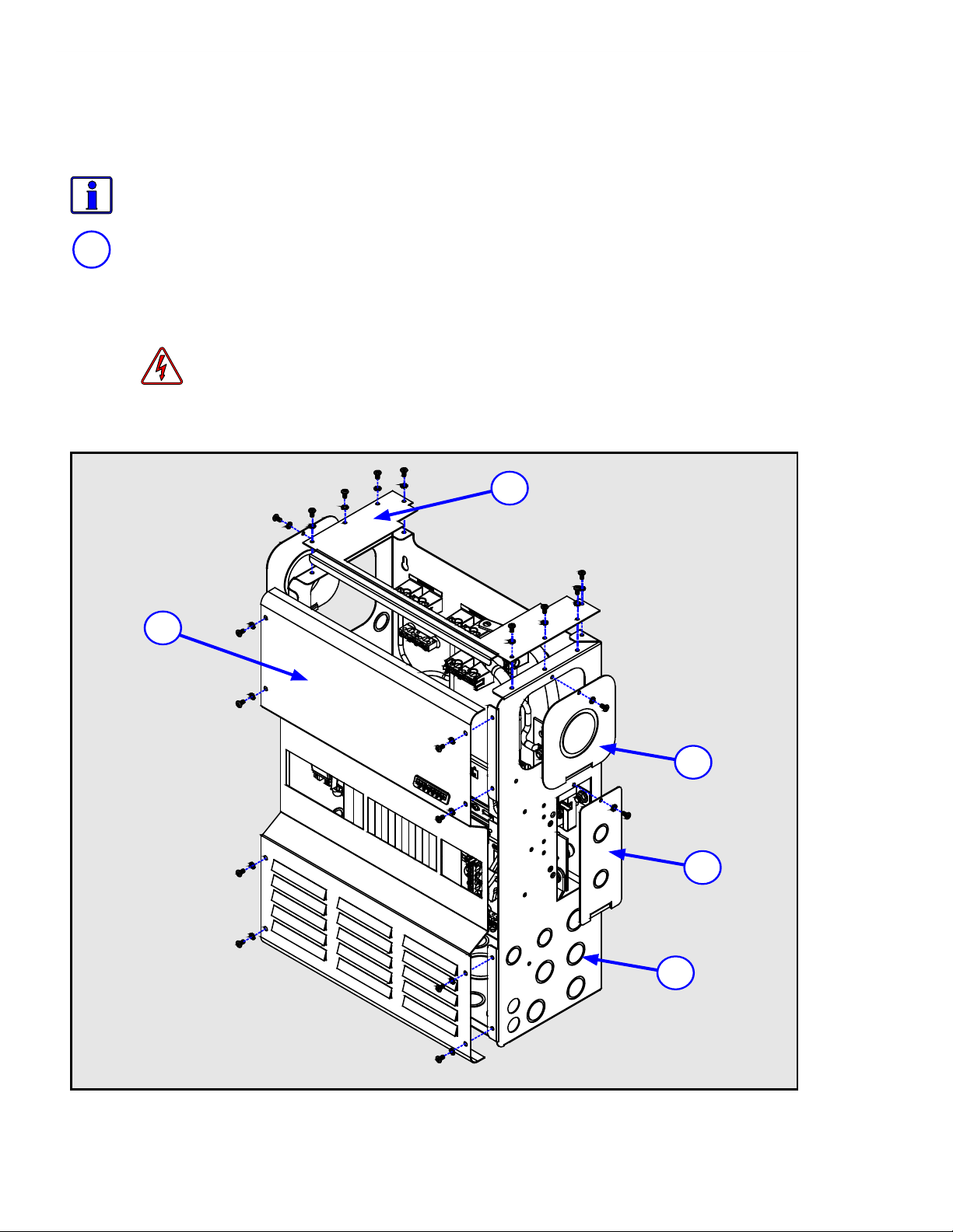
2.3 MP External Components
The main external
the MPDH enclosure (as shown in Figure 2-6) are described below:
components of the MPSL and MPSH enclosures (as shown in Figure 2-5) and
Info:
head, T25 T
1
Inv
This plate allows a Magnum inverter to sit on top of the MP enclosure, and allow the AC
and DC wiring to be easily routed from the inverter to the MP enclosure.
The inverter plate can be replaced with the Knockout Plate, which is used as an upper
conduit/safety plate. See Section A5 for more information on the Knockout Plate.
The external components are secured to the enclosure using #10-32 x 3/8” (Pan
orx driv
erter Plate - The MP enclosure is factory shipped with the inverter plate installed.
WARNING: To
MP enclosure, the Knockout Plate must be installed if the Magnum inverter is
removed for service and the AC bypass breaker is switched ON.
2
e) thread cutting screws and #10 lock washers.
prevent accidental access to live electrical circuits inside the
1
Figure 2-5, MPSL and MPSH External Components
© 2011 Magnum Energy, Inc.Page 7
3
4
5
Page 15
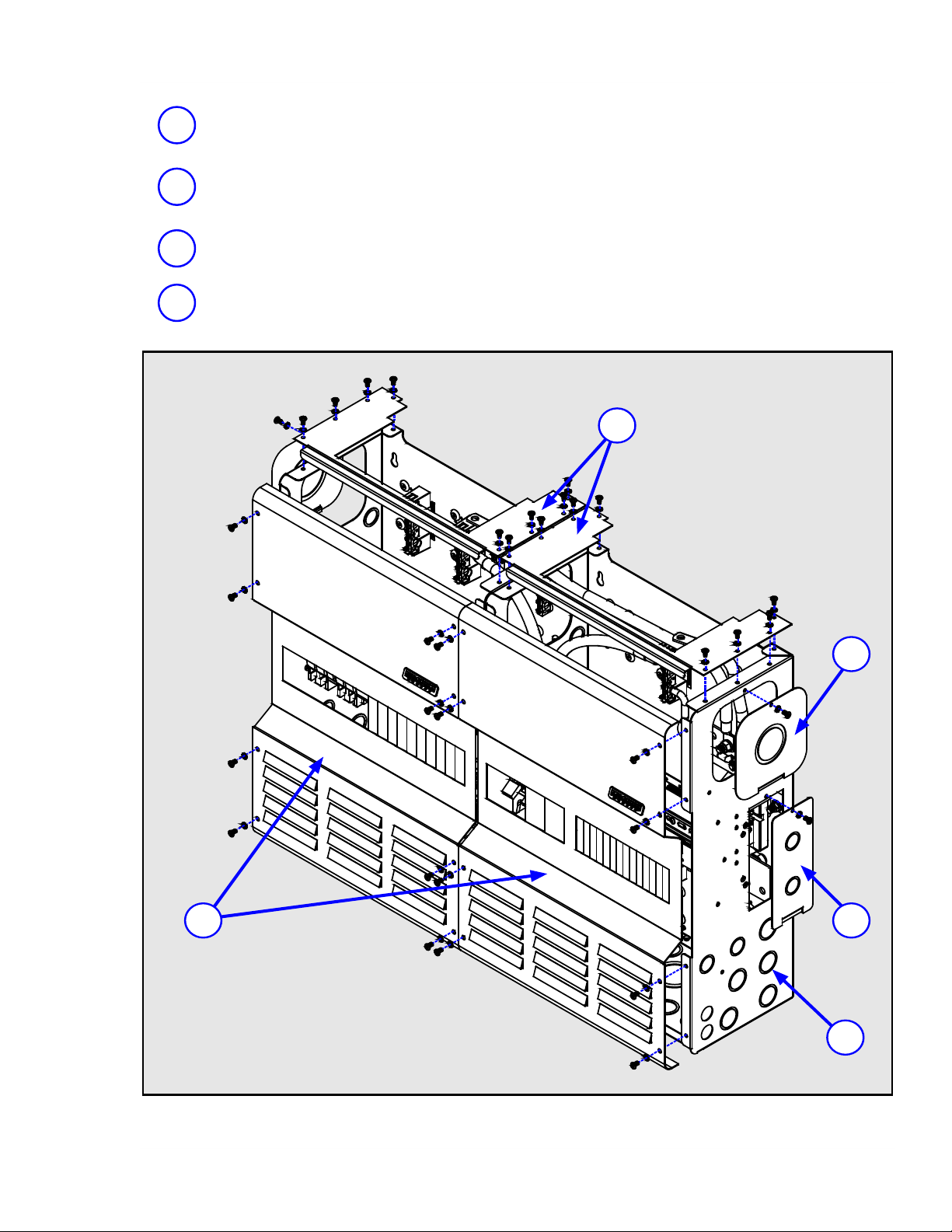
2.0 Introduction
2
3
4
5
Front Panel Cover
access the internal components. The front cover panels are equipped with rectangular
knockouts, to allow additional AC and DC circuit breakers to be installed.
Side
MP
and communications conductors to be routed from the main MP enclosure to a MPX
extension box (when used).
DC
battery monitor) and the DC ground stud.
Conduit
enclosure are provided to allow metal and PVC conduits. For dimensions and sizes, see
Figures 3-13 and 3-14.
Access
Shunt
Access
Knockouts
- The cover(s) on the front of the MP enclosures can be removed to
Plate (x2) - These access plates (one on each side) allow the power
Plate - This plate allows access to the DC shunt (for connecting a
Multiple sized knockouts on the side and bottom of the MP
-
1
3
2
4
5
Figure 2-6, MPDH External Components
© 2011 Magnum Energy, Inc.
Page 8
Page 16

2.0 Introduction
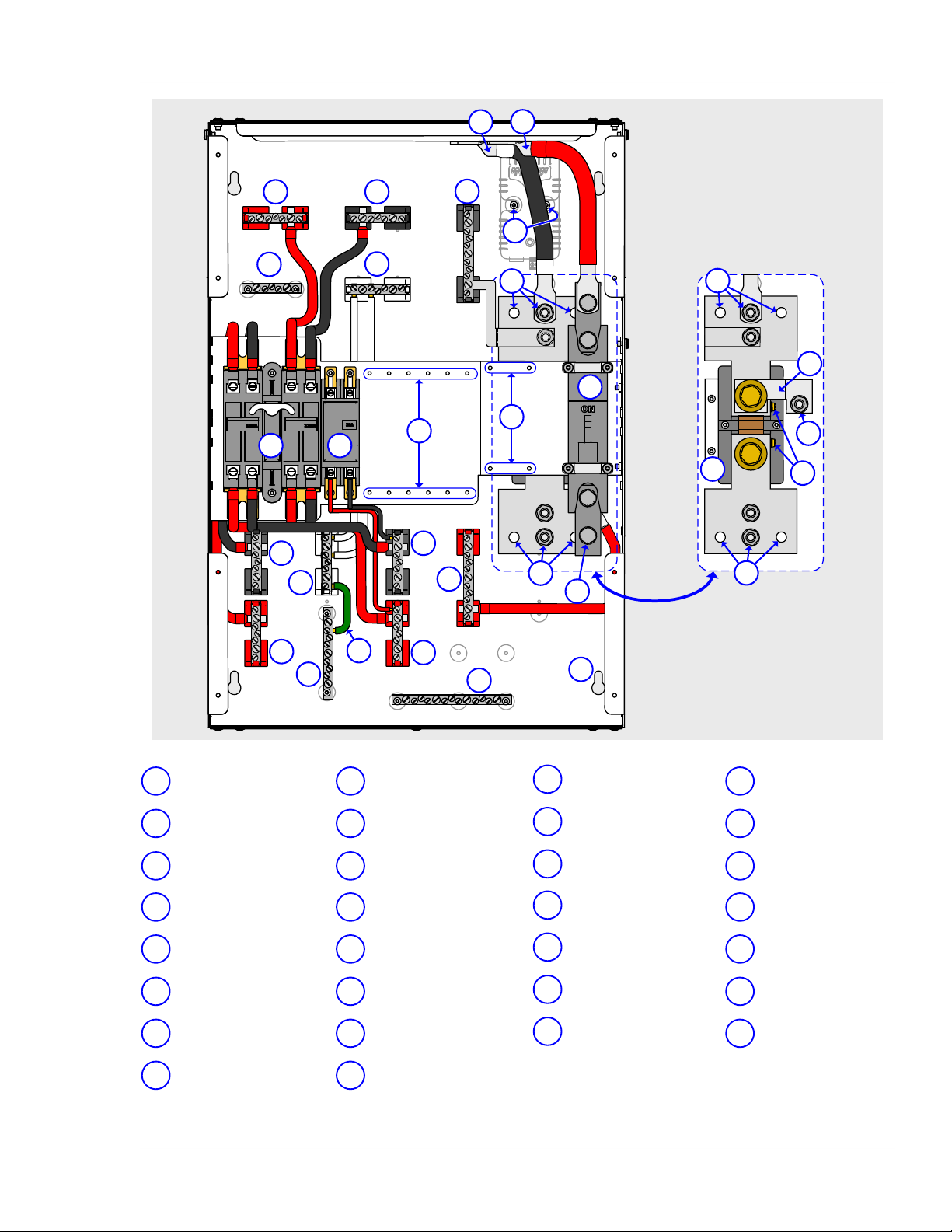
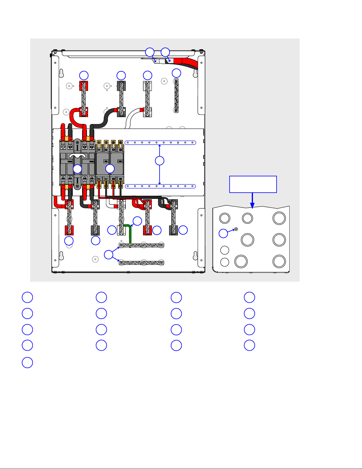
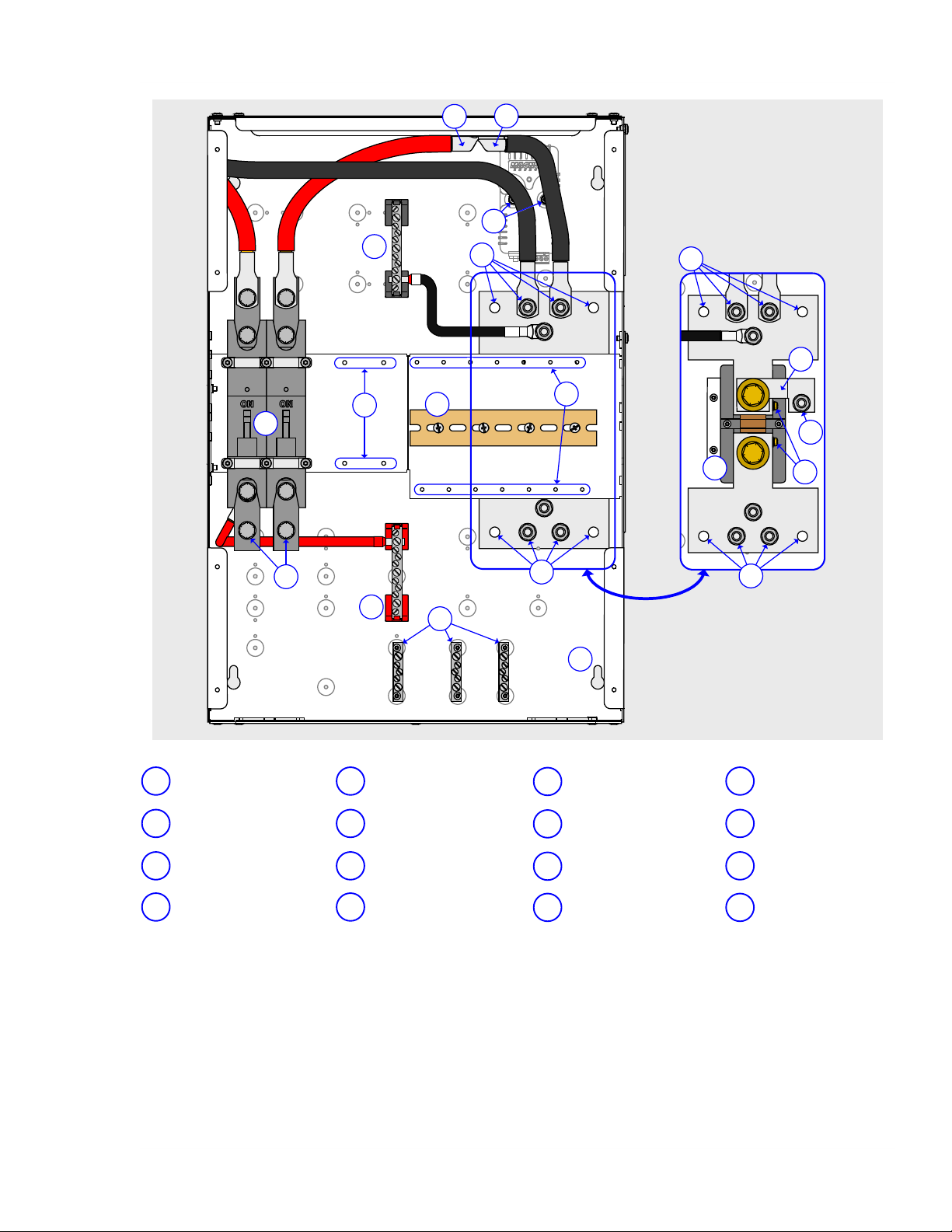
2.4 MP Internal Components
Additional
MPSL-30D (see Figure 2-7), the MPSL-60S (see Figure 2-8), the MPSH-30D (see Figure 2-9), and
the MPDH-30D (see Figures 2-10a and 2-10b) are listed alphabetically and described below:
components are located inside the MP enclosure. The components found inside the
Info:
A
compression terminals (no ring lugs required). The number of terminals available
depends on the particular busbar and the MP model.
Info:
common to each other as they are all connected to the MP chassis.
AC
GROUND
used to connect the incoming and outgoing AC circuit grounds to a common ground point.
AC LEG 1 IN Busbar - Connects incoming LEG 1 AC power from the grid or a generator to the
MP/inverter system. This busbar is used to connect the LEG 1 output of a 120/240V AC external
source (grid power or AC generator) to the MP enclosure. The AC LEG 1 IN busbar is connected to
the HOT 1 input of the inverter system (thru the inverter’s AC input breaker). The external source
is used by the inverter to charge the batteries and power downstream loads thru the inverter.
AC LEG 1 OUT Busbar - Supplies the LEG 1 power from the MP/inverter system to the AC loads.
This busbar is the connection point from the MP enclosure to the LEG 1 terminal in the electrical
panel powered by the inverter.
AC LEG 2 IN Busbar - Connects incoming LEG 2 AC power from the grid or a generator to the
MP/inverter system. This busbar is used to connect the LEG 2 output of a 120/240V AC external
source (AC generator or grid power) to the MP enclosure. The AC LEG 2 IN busbar is connected to
the HOT 2 input of the inverter system (thru the inverter’s AC input breaker). This external source
is used by the inverter to charge the batteries and power downstream loads thru the inverter.
AC LEG 2 OUT Busbar - Supplies the LEG 2 power from the MP/inverter system to the AC loads.
This busbar is the connection point from the MP enclosure to the LEG 2 terminal in the electrical
panel powered by the inverter.
AC NEUTRAL Busbars - The neutral leg for loads powered from the MP/inverter system and the
neutral leg for AC power supplied to the MP/inverter system by either a generator or grid. These
two busbars are the connection points for the AC neutrals in the system. The system neutrals
include: the neutral output from the external AC source (generator/grid), the neutral terminal in
the electrical panel that is powered by the inverter, and the input and output neutral terminals of
each inverter. Note: Both AC NEUTRAL busbars are electrically connected to each other.
All the busbars have dual hole sizes — the larger holes accept #14 to #1/0
WG
and the smaller holes accept #14 to #6 AWG — these holes have set-screw type
All AC Ground Busbars, DC Ground Busbars, and the DC Ground Stud are electrically
Busbar(s) - These busbars are connected to the MP enclosure chassis and are
• Installing MS-PAE Series inverters: Both neutral terminals are common with each other
within the MS-PAE Series, this means only one neutral from each MS-PAE inverter needs to
connect to the AC NEUTRAL busbar.
• Installing MS4024 inverters: The Neutral In and Neutral Out are not common with each
other within the MS4024; this means both input and output neutrals from each MS4024
inverter needs to connect to the AC NEUTRAL busbar.
AC NEUTRAL-GROUND Connection - A wire (green) connects the AC neutral to the system
ground. This green wire can be removed from the GROUND busbar if the primary AC neutral to
ground connection is made elsewhere in the system (see Section 3.10).
Battery Negative Connection - The bottom of the DC Shunt busbar is the connection point to
the negative terminal of the battery bank. This busbar is supplied with a 3/8-16 bolt and lock
washer to allow the battery cable to be connected.
© 2011 Magnum Energy, Inc.Page 9
Page 17

2.0 Introduction
Battery
point to the positive terminal of the battery bank. The DC disconnect provides a rear captive nut
to allow the battery cable to be front-connected using a 3/8-16 bolt and lock washer.
DC GROUND Busbar - This busbar is connected to the MP enclosure chassis and is used to tie
DC equipment grounds to a common point. This terminal is also used to connect the inverter/
MP/inverter system to the DC grounding electrode. If the DC grounding electrode conductor
is greater than #1/0 AWG, use the DC Ground Stud to connect to the DC grounding electrode
(i.e., ground rod).
DC Ground Stud - This 5/16-18 stud is connected to the MP enclosure chassis, and is provided
as a connection point to the DC grounding electrode when the conductor is larger than #1/0 AWG.
This stud also connects to the DC shunt through a busbar and serves as the DC negative to
ground connection point. If installing a PV-GFP device, this busbar must be removed (see Section 3.11). Note: For ground wires #1/0 AWG or smaller, use the DC GROUND busbar.
DC NEGATIVE Busbar - This busbar is connected to the battery bank negative through the
load side of the DC shunt. This busbar is the battery negative connection point for additional
DC circuits, such as from the DC negative output of a charge controller or when combining the
negatives of DC load circuit breakers. This busbar is rated to handle 120 amps.
DC NEGATIVE-GROUND Connection - This busbar connects the DC negative to the system
ground. It must be removed if the primary DC negative to ground connection is made elsewhere
in the system (see Section 3.11).
DC POSITIVE Busbar - This busbar is connected to the battery bank positive through the
bottom of the inverter DC disconnect. This busbar is the battery positive common point for
connecting additional DC circuits, such as from the output of a charge controller disconnect, the
DC positive feed to DC load breakers, and the positive connection to a battery status monitor.
This busbar is rated to handle 120 amps.
DC Shunt - A DC shunt installed in the DC negative side that is used to measure the amperage fl owing between the battery and the inverter (and any DC loads connected). This shunt is
pre-installed so that a battery monitor may be easily connected to display the current fl ow. See
Section A-2 for information on installing and wiring the ME-BMK-NS battery monitor inside the
MP enclosure. The MPSL-30D and MPSL-60S are supplied with a 500 amp/50mV DC shunt, and
the MPSH-30D and MPDH-30D have a 1000A/100mV DC shunt.
DC Shunt Voltage Sense Terminals - These two shunt terminals/screws serve as the sense
connections to the optional ME-BMK-NS battery monitor. When current is passed through the
shunt, the IR drop (AKA voltage drop) developed across it can be read by the battery monitor
to provide an accurate indication of the current fl owing through the shunt.
DIN Rail Track - For installing up to 1/2” (12.7mm) wide, DIN rail-mounted, Q-Frame type,
DC breakers. These breakers can be used for connecting DC loads or installing a PV-GFP device.
The track may be removed to allow 1” (25.4mm) wide, back-mounted, E-Frame type breakers
to be installed instead.
Enclosure Joining Screw/Washer - A #10-32 x 3/8” (Pan head, T25 Torx drive) thread
cutting screw and #10 lock washers are provided to join the two enclosures of the MPDH-30D
together – to have them at the same electrical potential. See Figure 3-16c for more information.
INV HOT 1 OUT Busbar - This busbar is the connection point for the HOT 1 output from each
installed inverter. The total output power combined from every inverter on this busbar is fed thru
the Inverter Bypass Breaker Assembly to the AC LEG 1 OUT Busbar.
INV HOT 2 OUT Busbar - This busbar is the connection point for the HOT 2 output from each
installed inverter. The total output power combined from every inverter on this busbar is fed thru
the Inverter Bypass Breaker Assembly to the AC LEG 2 OUT Busbar.
Positive Connection - The bottom of the inverter’s DC disconnect is the connection
© 2011 Magnum Energy, Inc.
Page 10
Page 18

2.0 Introduction
Inverter AC
circuit, a way to disconnect the AC input to the inverters, and overcurrent protection to the
inverter’s input wires when the minimum recommended AC wire sizes are used. Depending on
your MP model, the breaker provided for the inverter input will be either a double-pole 30 amp
(D30A) or a single-pole 60 amp (S60A) AC breaker.
The double-pole 30 amp AC breaker is provided on the MPSL-30D, MPSH-30D, and MPDH-30D
models to allow 120/240V AC inverters — up to 30 AC amps per leg pass-thru capability — to be
connected. The MPSL-30D and MPSH-30D come with one double-pole 30A input breaker and the
MPDH-30D comes with two double-pole 30A breakers. These three models require a double-pole
30A breaker for each additional inverter installed in a parallel-stacked confi guration.
The single 60 amp AC breaker is provided on the MPSL-60S models to allow 120V AC inverters
— up to 60 AC amps pass-thru capability — to be connected. If connecting MS4024’s in a
series-stacked confi guration, an additional single pole 60A breaker for the second MS4024 will
be required (as provided in the MPX extension kit).
Inverter Bypass Breaker Assembly - The Inverter AC Bypass Breaker Assembly is pre-wired
at the factory and consists of the inverter bypass switch and the inverter AC output disconnect
breaker. This breaker assembly provides a way to disconnect the AC output of the inverter
system, and to directly connect the AC input to the AC output by bypassing the inverter system.
The MPSL-30D and MPSL-60S are installed with a double-pole 60-amp AC bypass breaker
assembly, and the MPSL-30D and MPDH-30D are equipped with a double-pole 125-amp AC
bypass breaker assembly.
Inverter DC Disconnect Breaker - This 250 amp DC disconnect is a high interruption capacity,
magnetic-hydraulic, DC circuit breaker. These breakers were specifi cally designed and tested
to work with Magnum inverters to provide the delay time needed to minimize nuisance breaker
tripping. It provides an easy and convenient way to isolate the inverter from the battery, and
meets the NEC/CEC requirements for DC overcurrent protection when the size and length of the
battery-to-inverter cables are installed in accordance with the installation instructions in this
manual. These breakers have front-accessible connections, each provided with 3/8-16 Hex head
bolts with lock washers.
Inverter’s DC Negative Connection - Connects to Magnum inverter’s DC negative terminal.
Inverter’s DC Positive Connection - Connects to Magnum inverter’s DC positive terminal.
Mounting Dimples, BMK (x2) - These dimples allow the optional ME-BMK-NS (Battery Monitor
Kit without DC shunt) to be installed. Two #8-32 x 1/2” (T20 Torx drive) thread cutting screws
are provided to mount the battery monitor. See Section A2 for more information on mounting
the battery monitor.
Mounting Holes, Inv AC Input Breakers - Used to install additional Inverter AC Input
Breakers, which provide protection to each inverter’s AC input circuit.
Mounting Holes, Inv DC Backmount Breakers - For installing 1” (25.4mm) wide, back-
mounted, E-Frame type, DC breakers. These breakers can be used for connecting DC loads or
installing a PV-GFP device.
Mounting Holes, Inv DC Disconnect Breakers - Used to install additional Inverter DC
Disconnect Breakers, which isolate the inverter from the battery. These breakers meet the NEC/
CEC requirements for DC overcurrent protection when used in accordance with the installation
instructions in this manual.
Mounting Keyholes, MP Enclosure (x4) - Four keyholes for mounting the enclosure. See
Figures 3-5 or 3-6 for size information on these keyholes.
Input Breakers - These breakers provide protection to the inverter’s AC input
© 2011 Magnum Energy, Inc.Page 11
Page 19
2.0 Introduction
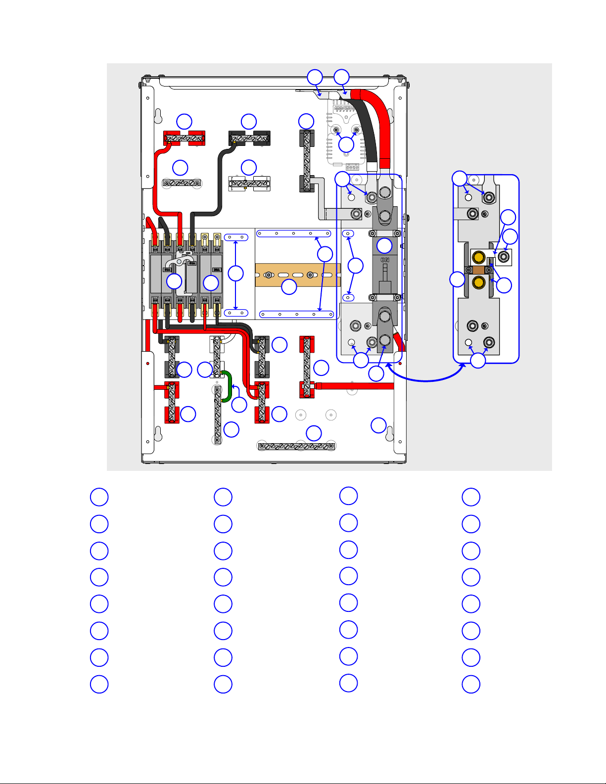
29
30
32
3 4
16
10
11
8
5
7
17
26
25
24
21
18
20
27
6
14
15
12
19
28
23
1
13
9
22
31
9
22
2
DC SHUNT
(
MOUNTED TO ENCLOSURE
UNDER INVERTER DC
OMPONENTS
C
DISCONNECT BREAKERS)
IN/OUT)
TIVE
Figure 2-7, MPSL-30D Internal Components
INVERTER’S DC NEGA
1
CONNECTION (CABLE)
DC NEGATIVE BUSBAR
5
INVERTER DC NEGATIVE
9
ONNECTIONS (BUSBAR)
C
DIN RAIL TRACK
13
AC LEG 1 OUT BUSBAR
17
AC LOAD PANEL)
(TO
DC POSITIVE BUSBAR
21
AC GROUND BUSBAR
25
(SOURCE/LOAD
DC NEGATIVE-
29
GROUND CONNECTION
© 2011 Magnum Energy, Inc.
INVERTER’S DC POSITIVE
2
CONNECTION (CABLE)
MOUNTING DIMPLES, BMK
6
10
14
18
22
26
30
ME-BMK-NS)
(FOR
INVERTER BY
ASSEMBLY (60A)
MOUNTING HOLES, DC
BACKMOUNT BREAKERS
AC NEUTRAL BUSBAR
(SOURCE/LOAD
BATTERY NEGATIVE
CONNECTIONS
AC LEG 2 IN BUSBAR
GEN OR GRID)
(FROM
DC GROUND STUD
PASS BREAKER
IN/OUT)
INV HOT 2 OUT BUSBAR
3
7
11
15
NVERTER OUTPUT)
(FROM I
AC GROUND BUSBAR
(INVERTER INPUT/O
INVERTER AC INPUT
BREAKER (
D30A)
MOUNTING HOLES, INV DC
DISCONNECT BREAKER
AC NEUTRAL-
19
GROUND CONNECTION
BATTERY POSITIVE
23
CONNECTION
DC GROUND BUSBAR
27
DC SHUNT
31
(500A/50MV)
UTPUT)
INV HOT 1 OUT BUSBAR
4
8
12
16
20
24
28
32
NVERTER OUTPUT)
(FROM I
AC NEUTRAL BUSBAR
(INVERTER INPUT/O
MOUNTING HOLES, TO ADD
AC INPUT BREAKER
INV
INVERTER DC DISCONNECT
BREAKER
AC LEG 1 IN BUSBAR
GEN OR GRID)
(FROM
AC LEG 2 OUT BUSBAR
AC LOAD PANEL)
(TO
MOUNTING KEYHOLES,
MP ENCLOSURE (
DC SHUNT VOLT
SENSE TERMINALS/SCREWS
Page 12
UTPUT)
X4)
AGE
Page 20
2.0 Introduction
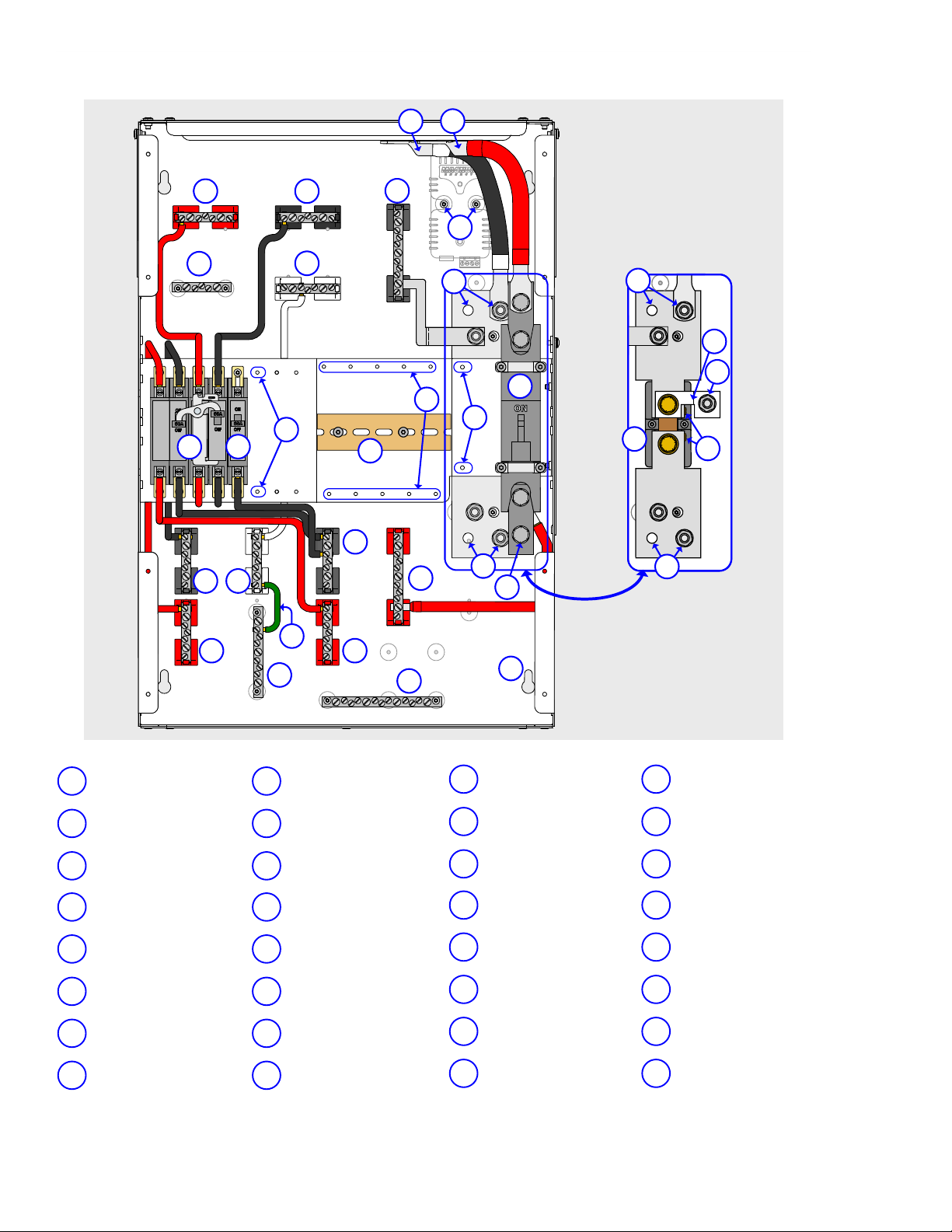
29
30
32
3 4
16
10
8
5
7
17
26
25
24
21
18
20
27
6
14
15
12
19
28
23
1
13
9
22
31
9
22
11
2
DC SHUNT
MOUNTED TO ENCLOSURE
(
UNDER INVERTER DC
C
OMPONENTS
DISCONNECT BREAKERS)
INVERTER’S DC NEGA
1
CONNECTION (CABLE)
DC NEGATIVE BUSBAR
5
INVERTER DC NEGATIVE
9
ONNECTIONS (BUSBAR)
C
DIN RAIL TRACK
13
AC LEG 1 OUT BUSBAR
17
AC LOAD PANEL)
(TO
DC POSITIVE BUSBAR
21
AC GROUND BUSBAR
25
(SOURCE/LOAD
DC NEGATIVE-
29
GROUND CONNECTION
IN/OUT)
TIVE
Figure 2-8, MPSL-60S Internal Components
INVERTER’S DC POSITIVE
2
CONNECTION (CABLE)
MOUNTING DIMPLES, BMK
6
10
14
18
22
26
30
ME-BMK-NS)
(FOR
INVERTER BY
ASSEMBLY (60A)
MOUNTING HOLES, DC
BACKMOUNT BREAKERS
AC NEUTRAL BUSBAR
(SOURCE/LOAD
BATTERY NEGATIVE
CONNECTIONS
AC LEG 2 IN BUSBAR
GEN OR GRID)
(FROM
DC GROUND STUD
PASS BREAKER
IN/OUT)
INV HOT 2 OUT BUSBAR
3
7
11
15
19
23
27
31
NVERTER OUTPUT)
(FROM I
AC GROUND BUSBAR
(INVERTER INPUT/O
INVERTER AC INPUT
BREAKER (
MOUNTING HOLES, INV DC
DISCONNECT BREAKER
AC NEUTRALGROUND CONNECTION
BATTERY POSITIVE
CONNECTION
DC GROUND BUSBAR
DC SHUNT
(500A/50MV)
UTPUT)
SINGLE 60A)
© 2011 Magnum Energy, Inc.Page 13
INV HOT 1 OUT BUSBAR
4
8
12
16
20
24
28
32
NVERTER OUTPUT)
(FROM I
AC NEUTRAL BUSBAR
(INVERTER INPUT/O
MOUNTING HOLES, TO ADD
AC INPUT BREAKER
INV
INVERTER DC DISCONNECT
BREAKER
AC LEG 1 IN BUSBAR
GEN OR GRID)
(FROM
AC LEG 2 OUT BUSBAR
AC LOAD PANEL)
(TO
MOUNTING KEYHOLES,
MP ENCLOSURE (
DC SHUNT VOLT
SENSE TERMINALS/SCREWS
UTPUT)
X4)
AGE
Page 21
2.0 Introduction
`
3 4
14
10 11
8
5
7
15
24
22
21
18
16
17
25
6
12
23
26
20
1
19
29
27
28
30
19
13
9
9
2
DC SHUNT
MOUNTED TO ENCLOSURE
(
UNDER INVERTER DC
C
OMPONENTS
DISCONNECT BREAKER)
INVERTER’S DC NEGA
1
CONNECTION (CABLE)
DC NEGATIVE BUSBAR
5
INVERTER DC NEGATIVE
9
ONNECTIONS (BUSBAR)
C
MOUNTING HOLES, INV DC
13
DISCONNECT BREAKER
AC LEG 1 IN BUSBAR
17
(FROM
AC LEG 2 OUT BUSBAR
21
(TO
DC GROUND BUSBAR
25
DC SHUNT
29
(1000A/100MV)
GEN OR GRID)
AC LOAD PANEL)
TIVE
Figure 2-9, MPSH-30D Internal Components
© 2011 Magnum Energy, Inc.
INVERTER’S DC POSITIVE
2
CONNECTION (CABLE)
MOUNTING DIMPLES, BMK
6
10
14
18
22
26
30
ME-BMK-NS)
(FOR
INVERTER BY
ASSEMBLY (125A)
INVERTER DC DISCONNECT
BREAKER
DC POSITIVE BUSBAR
AC GROUND BUSBAR
(SOURCE/LOAD
MOUNTING KEYHOLES,
MP ENCLOSURE (
DC SHUNT VOL
SENSE TERMINALS/SCREWS
PASS BREAKER
IN/OUT)
X4)
TAGE
INV HOT 2 OUT BUSBAR
3
7
11
15
19
23
27
NVERTER OUTPUT)
(FROM I
AC GROUND BUSBAR
(INVERTER INPUT/O
INVERTER AC INPUT
BREAKER (D30A)
AC LEG 1 OUT BUSBAR
AC LOAD PANEL)
(TO
BATTERY NEGATIVE
CONNECTIONS
AC NEUTRALGROUND CONNECTION
DC NEGATIVEGROUND CONNECTION
UTPUT)
INV HOT 1 OUT BUSBAR
4
8
12
16
20
24
28
NVERTER OUTPUT)
(FROM I
AC NEUTRAL BUSBAR
(INVERTER INPUT/O
MOUNTING HOLES, TO ADD
AC INPUT BREAKER
INV
AC NEUTRAL BUSBAR
SOURCE/LOAD
BATTERY POSITIVE
CONNECTION
AC LEG 2 IN BUSBAR
GEN OR GRID)
(FROM
DC GROUND STUD
Page 14
UTPUT)
IN/OUT)
Page 22
2.0 Introduction
3
4
8
5
7
10
14
11
12
6
13
15
9
16
1
2
17
INVERTER’S DC NEGA
1
CONNECTION (CABLE)
AC NEUTRAL BUSBAR
5
(INVERTER INPUT/O
MOUNTING HOLES, TO ADD
9
AC INPUT BREAKERS
INV
AC NEUTRAL-
13
GROUND CONNECTION
ENCLOSURE JOINING
17
CREW/WASHER
S
RIGHT SIDE VIEW
(LOWER
UTPUT)
INV HOT 2 OUT BUSBAR
3
7
11
15
NVERTER OUTPUT)
(FROM I
INVERTER BY
PASS BREAKER
ASSEMBLY (125A)
AC LEG 1 OUT BUSBAR
AC LOAD PANEL)
(TO
AC LEG 1 IN BUSBAR
GEN OR GRID)
(FROM
TIVE
UTPUT)
2
6
10
14
INVERTER’S DC POSITIVE
CONNECTION (CABLE)
AC GROUND BUSBAR
(INVERTER INPUT/O
AC LEG 2 OUT BUSBAR
AC LOAD PANEL)
(TO
AC LEG 2 IN BUSBAR
GEN OR GRID)
(FROM
SECTION)
INV HOT 1 OUT BUSBAR
4
8
12
16
NVERTER OUTPUT)
(FROM I
INVERTER AC INPUT
BREAKERS (D30A
AC NEUTRAL BUSBAR
(SOURCE/LOAD
AC GROUND BUSBARS
(SOURCE/LOAD
X2)
IN/OUT)
IN/OUT)
Figure 2-10a, MPDH-30D (AC Side) Internal Components
© 2011 Magnum Energy, Inc.Page 15
Page 23
2.0 Introduction
31
30
32
33
28
20
28
23
21
18
26
19
22
1
2
24
20
27
25
28
29
DC SHUNT
MOUNTED TO ENCLOSURE
(
UNDER INVERTER DC
C
OMPONENTS
DISCONNECT BREAKERS)
DC NEGATIVE BUSBAR
18
MOUNTING HOLES, INV DC
22
DISCONNECT BREAKER
DC POSITIVE BUSBAR
26
DC NEGATIVE-
30
GROUND CONNECTION
Figure 2-10b, MPDH-30D (DC Side) Internal Components
© 2011 Magnum Energy, Inc.
MOUNTING DIMPLES, BMK
19
23
27
31
ME-BMK-NS)
(FOR
DIN RAIL TRACK
DC GROUND BUSBARS
(X3)
DC SHUNT
(1000A/100MV)
INVERTER DC NEGATIVE
20
ONNECTIONS (BUSBAR)
C
MOUNTING HOLES, DC
24
BACKMOUNT BREAKERS
BATTERY NEGATIVE
28
CONNECTIONS
DC GROUND STUD
32
INVERTER DC DISCONNECT
21
BREAKERS (X
BATTERY POSITIVE
25
CONNECTIONS (X
MOUNTING KEYHOLES
29
33
EACH ENCLOSURE)
(X4 FOR
DC SHUNT VOLT
SENSE TERMINALS/SCREWS
2)
2)
AGE
Page 16
Page 24

3.0 Installation
3.0 Installation
This section describes the requirements and recommendations for installing the MP enclosure.
Info:
MPSL/MPSH
inverters are required, the optional MPX enclosures are used. Refer to the MPX Extension
Owner’s Manual (PN:64-1015) for information on installing these additional inverters.
This installation section primarily explains the installation of one inverter on the
enclosure,
and two inverters on the MPDH enclosure. When additional
3.1 Pre-Installation
Before proceeding with the installation:
• Please read and familiarize yourself with the entire Installation section.
• Read and ensure you understand the “Important Product Safety Information” and the “Important
Battery Safety Instructions” at the beginning of this manual.
• Be aware of all safety and electrical codes which must be met.
• Inspect all shipping cartons for evidence of physical damage. If a shipping carton is damaged,
request that the shipping agent be present for inspection when the carton is opened.
• Unpack the MP enclosure box and remove the components. Verify that you have the components
and hardware as listed below in Section 3.1.1 (and shown in Figures 3-1 and 3-2).
• Use the information in Section 3.1.2 to help identify most of the materials and tools required
for the installation.
• Read the information provided in Section 3.1.3 to properly plan for the installation.
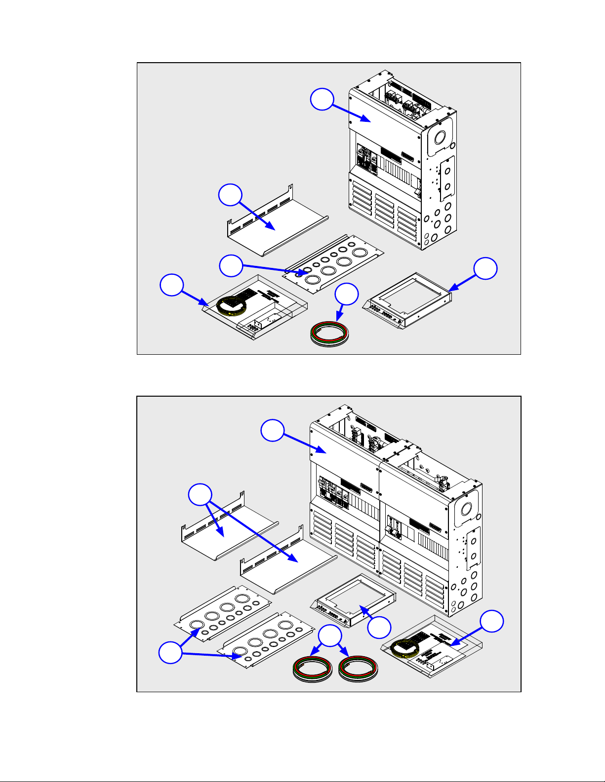
3.1.1 MP Parts Included
Refer to Figures 3-1 or 3-2 (and the item list below) for you particular MP model to verify the
nece
ssary parts are included. If items are missing, contact your authorized Magnum Energy dealer
or Magnum Energy.
1a
1b
2
3
4
5
6
Info: Save your proof-of-purchase as a record of your ownership; it will be needed if
the unit should require in-w
L or MPSH Models - The MPSL-30D, MPSL-60S, and MPDH-30D use a single enclosure
MPS
to provide the AC/DC breakers, busbars, and wiring for the inverter’s AC and DC circuits.
H Model - The MPDH-30D uses two enclosures, one enclosure (AC Side) provides
MPD
the AC breakers, busbars, and wiring for the inverters AC circuits; and, the other
enclosure (DC Side) provides the DC breakers, busbars, and wiring for the inverter’s
DC circuits.
Inverter Hood - The
that is mounted on a Magnum Panel to prevent items from falling into the ventilation
openings at the top of the inverter. See Section A3 for more information on this hood.
Knockout Plate -
safety plate. See Section A5 for more information on this plate.
RTR (Router) Bracket Kit - This kit consists of the router bracket and the hardware
ME-
to attach the ME-RTR (i.e., Router) to the side of the MP enclosure. This kit is not
provided with the MPSL-60S model. See Section A4 for more information on this kit.
Hardware Kit - This hardware kit consists of the Charge Controller bracket and
MP
hardware (see Section A1), the owner’s manual, communications cables (see Section
3.8), and a front cover label set (see Section 3.15).
MP AC Wiring
the inverter’s AC input and output terminals to the MP enclosure. See Section 3.6.3 for
more information on this kit.
The knockout plate is provided as an upper conduit plate, or as a
Kit - This wiring kit provides the appropriate AC wires needed to connect
arranty service.
inverter hood is required to be installed over a Magnum inverter
© 2011 Magnum Energy, Inc.Page 17
Page 25
3.0 Installation
1a
2
3
5
6
Figure 3-1, Parts Included - MPSL and MPSH Models
1b
2
4
3
Figure 3-2, Parts Included - MPDH Models
© 2011 Magnum Energy, Inc.
6
4
5
Page 18
Page 26
3.0 Installation
3.1.2
The following material and tools may be required for installing this equipment:
Materials
Conduit, str
•
• Electrical tape • Wire ties
• Conductors/cables for wiring AC source/load • A strong back
• Battery cables for wiring to battery bank • Conductors for system ground
Tools
• Flat-blade 1/4” screwdrivers • Insulated pliers • Wire cutters/strippers
• Phillips screwdriver • Pencil or marker • AC/DC Voltmeter
• Drill and drill bits • 1/2” open end wrench • Level
• Torque wrenches • Ratchet drives
• Torx screwdrivers (T15, T20 and T25 drive)
Required Material and Tools
ain-reliefs, and appropriate fi
ttings • 1/4” mounting bolts and lock washers
3.1.3 Planning
Installing the MP/inverter system can be fairly straightforward if you take time to plan before
the fi
turning
common, costly mistakes.
To assist you in planning and designing your installation, review the simplifi ed system diagram
shown in Figure 3-3 for parallel-stacked inverter installations, or Figure 3-4 for series-stacked
inverter installations. These drawings are a simple overview of the MP/inverter installation. They
are not intended to provide detailed information, override or restrict any national or local electrical
codes, nor should they be the determining factor as to whether the installation is compliant – that
is the responsibility of the electrician and the onsite inspector.
rst screw. The more thorough you plan, the more time you will save, and avoid
WARNING: Installations should
or certifi ed electrician. It is the installer’s responsibility to determine which safety
codes and standards apply, and to ensure that all applicable installation requirements
are followed. Applicable installation codes vary depending on the specifi c location and
application of the installation.
Info: Detailed MP/inv
depending on you MP model.
The installation section uses the following steps to perform the MP/inverter installation:
• Find the appropriate location (Section 3.2)
• Prepare the MP enclosure and inverter (Section 3.3)
• Mounting the MP enclosure and inverter (Section 3.4)
• Beware of wiring guidelines/safety (Section 3.5)
• Wire AC circuit (Section 3.6)
• Wire DC circuits (Section 3.7)
• Wire communications cables (Section 3.8)
• Removing negative or neutral to ground connections (Sections 3.9 and 3.10)
• Determine the system ground (Section 3.11)
• Perform a fi nal installation checklist (Section 3.12)
• Perform a functional test (Section 3.13)
• Attach the front covers (Section 3.14)
• Apply external labels (Section 3.15)
erter system wiring drawings are provided in Section 4.0,
be performed by qualifi ed personnel, such as a licensed
© 2011 Magnum Energy, Inc.Page 19
Page 27
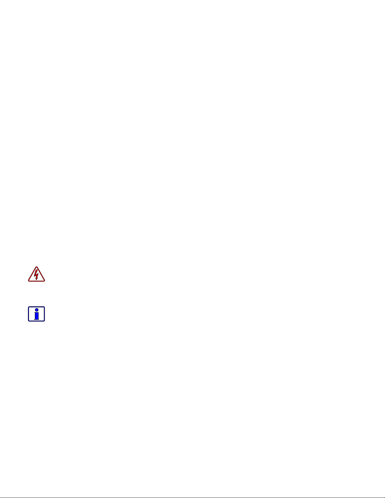
ME-AGS-N
Auto Gen Start Controller
(Magnum Accessory)
ON
OFF
ON
OFF
ON
OFF
ON
OFF
ON
OFF
ON
OFF
ON
OFF
ON
OFF
ON
OFF
ON
OFF
ON
OFF
ON
OFF
ON
OFF
G
ENERATOR POWER
(120/240VAC OUPUT)
UTILITY POWER
(120/240VAC OUTPUT)
AC
Transfer
Switch
#3
MS-PAE
I
NVERTER
(SLAVE)
F
l
u
x
C
a
p
a
c
i
t
o
r
G
e
n
e
r
a
t
o
r
ELECTRICAL PANEL*
(120/240VAC LOADS)
BATTERY
BANK
*A MAIN
PANEL AND SUB-PANEL
MAY BE REQUIRED
#2
MS-PAE
I
NVERTER
(SLAVE)
#4
MS-PAE
I
NVERTER
(SLAVE)
#1
MS-PAE
INVERTER
(MASTER)
AC SIDE
ME-BMK-NS
Battery Monitor
(Magnum Accessory)
DC SIDE
Magnum Panel (AC Side)
Includes Inverter Bypass &
AC Input/Output Breakers
ME-RTR
Router -
required
to stack
MS-PAE
inverters
in parallel
(Magnum
Accessory)
Maximum MS-PAE inverters that can be stacked in parallel:
MPSL-30D = maximum of two MS-PAE inverters
MPSH-30D = maximum of three MS-PAE inverters
MPDH-30D = maximum of four MS-PAE inverters
Magnum Panel
(DC side)
Includes DC Shunt
& DC Disconnects
3.0 Installation
Figure 3-3, MP Series Simplifi
© 2011 Magnum Energy, Inc.
ed Parallel-Stacked Installation Diagram
Page 20
Page 28
3.0 Installation
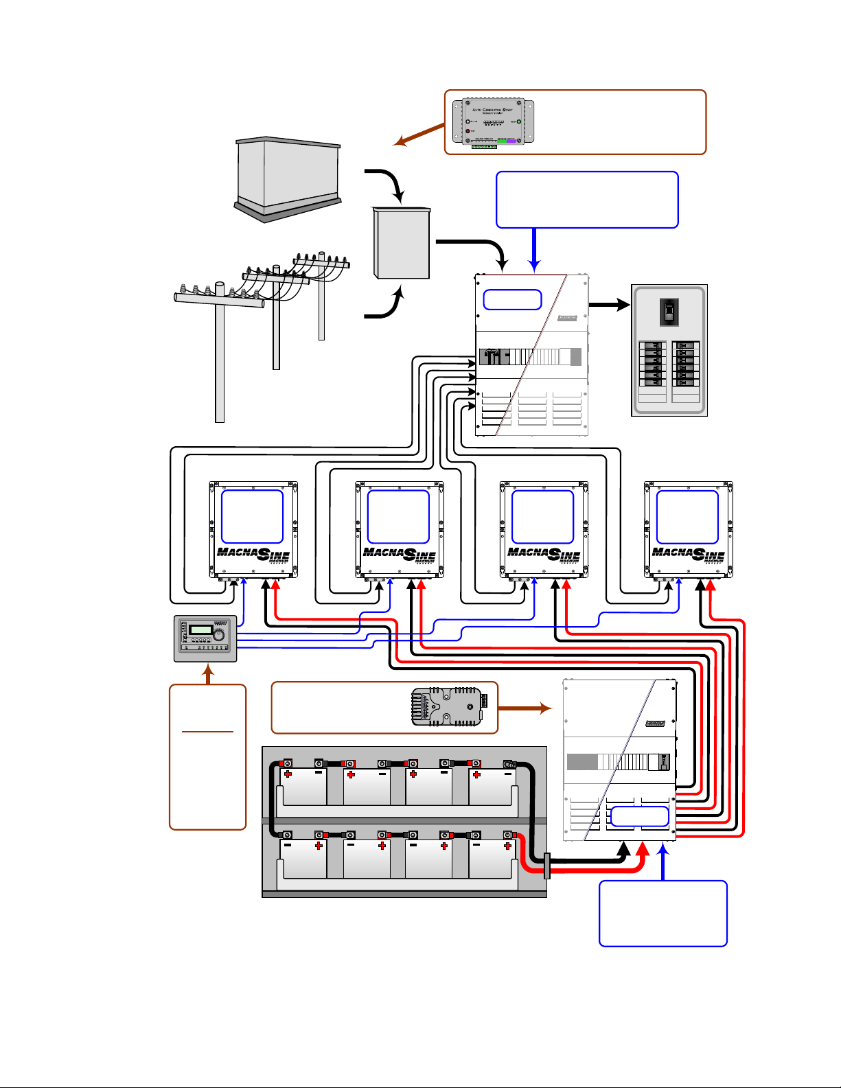
MS4024
INVERTER
ME-AGS-N
Auto Gen Start Controller
(Magnum Accessory)
ON
OFF
ON
OFF
ON
OFF
ON
OFF
ON
OFF
ON
OFF
ON
OFF
ON
OFF
ON
OFF
ON
OFF
ON
OFF
ON
OFF
ON
OFF
GENERATOR POWER
(120/240VAC OUPUT)
UTILITY POWER
(120/240VAC OUTPUT)
AC
Transfer
Switch
F
l
u
x
C
a
p
a
c
i
t
o
r
G
e
n
e
r
a
t
o
r
ELECTRICAL PANEL*
(120/240VAC L
OADS)
BATTERY
BANK
*A MAIN PANEL AND SUB-PANEL
MAY BE REQUIRED
AC SIDE
ME-BMK-NS
Battery Monitor
(Magnum Accessory)
DC SIDE
MPSL-60S (AC Side)
Includes Inverter Bypass &
AC Input/Output Breakers
ME-ARC (x2)
Advanced Remotes
- for inverter set up
and monitoring
(Magnum
Accessory).
The ME-RTR may
be used if identical
settings are used
on both inverters.
Series Stacking Cable,
required to stack MS4024
inverters in series.
(Magnum Accessory).
Included with MPXS-60S
Extension.
MPSL-60S allows a maximum of two
MS4024's to be stacked in series
MPSL-60S (DC side)
Includes DC Shunt &
DC Disconnects
MS4024
INVERTER
Figure 3-4, MP Series Simplifi
ed Series-Stacked Installation Diagram
© 2011 Magnum Energy, Inc.Page 21
Page 29

3.0 Installation
3.2
Choosing an appropriate location for the MP/inverter system should be determined early in the
installation process; install it only in a location that meets the following requirements:
Indoors ment away from sources of high temperature and moisture. The MP enclosure uses plated copper
busbars, powder coated metal components, and plated fasteners, which means it is very tolerant to corrosive or condensing environments (one in which humidity and/or temperature change
causes water to form on components). However, inverters are complex microprocessor controlled
devices and should be treated as sophisticated electronic devices, such as computers or stereo
equipment. When selecting the location for the MP/inverter system, don’t think of it in the same
terms as the other connected equipment, e.g., batteries, generators, etc. When inverters are
exposed to a corrosive or condensing environment their life will be shorten, and damage because
of corrosion is not covered by the product warranty.
Ventilation - If a Magnum inverter is installed on the MP enclosure, the inverter will pull in air
through the intake vents. In order for the inverter to provide full output power and avoid overtemperature fault conditions, do not cover or block the MP enclosure ventilation openings or install
it in an area with limited airfl ow. At the minimum, allow 3 inches of clearance to the left and right
of the MP enclosure to provide adequate ventilation.
Close to the Battery Bank - The MP enclosure/inverter system should be located as close to the
batteries as possible. This is to ensure the battery cable length is kept short. Long DC wires tend
to lose effi ciency and reduce the overall performance of an inverter. However, the MP enclosure,
the inverter, and any other equipment that can spark (or that corrosion could damage) should not
be installed in the same compartment/room as the batteries, or mounted where it will be exposed
to gases produced by the batteries. These gases are corrosive and will damage this equipment;
also, if these gases are not ventilated and if allowed to collect, they could ignite and cause an
explosion. Consult your battery supplier for proper installation requirements.
Location
The MP/inv
erter system must be mounted indoors in a relatively clean and dry environ-
Info: Consult the inverter owner’s manual to determine the proper inverter-to-battery
ble size for the distance used. However, this cable must not be sized any smaller than
ca
0000 (4/0) AWG if the DC disconnect breaker in the MP enclosure will also be used as
the overcurrent device. If a cable smaller than 4/0 AWG is used, an appropriately sized
fuse must be installed to provide overcurrent protection to this smaller cable.
Safe - Keep any fl ammable/combustible material (e.g., paper, cloth, plastic, etc.) that may be
ignited by heat, sparks or fl ames at a minimum distance of 12 feet away from the MP/inverter
system. Do not install the MP/inverter system in any area that contains extremely fl ammable liquids like gasoline or propane, or in locations that require ignition-protected devices. Sparks from
relays, circuit breakers, etc., could ignite the fumes or spills.
Accessible - Do not block access to the front of the MP enclosure. Maintain at least a 36” (91 cm)
clear space in front to access the AC and DC wiring terminals and connections inside the MP enclosure, as they will need to be checked and tightened periodically.
RFI - Most inverters can create RFI (Radio Frequency Interference). Keep this in mind when determining the placement of the MP/inverter system. You should locate the MP/inverter system as
far away as possible from any electronic equipment susceptible to radio frequency and electromagnetic interference.
Expandability - The MP enclosure was specifi cally designed to allow multiple inverters to be connected together. Keep in mind as your power needs grow, you can connect additional inverters
(using MPX enclosures - up to your models maximum inverter capability) to increase your power
capability. Use Figures 3-5 or 3-6 (depending on your MP model) to determine if you are allowing
the appropriate vertical and horizontal room to expand your MP/inverter system.
Rodent Proof - Ensure the MP/inverter system is located in an area that prevents rodents and
insects from entering and damaging wires/components – the MP/inverter can provide a warm
habitat in a cold environment. Mesh screens or nets may need to be installed over any openings
to ensure the unit is kept rodent free and well ventilated.
© 2011 Magnum Energy, Inc.
Page 22
Page 30
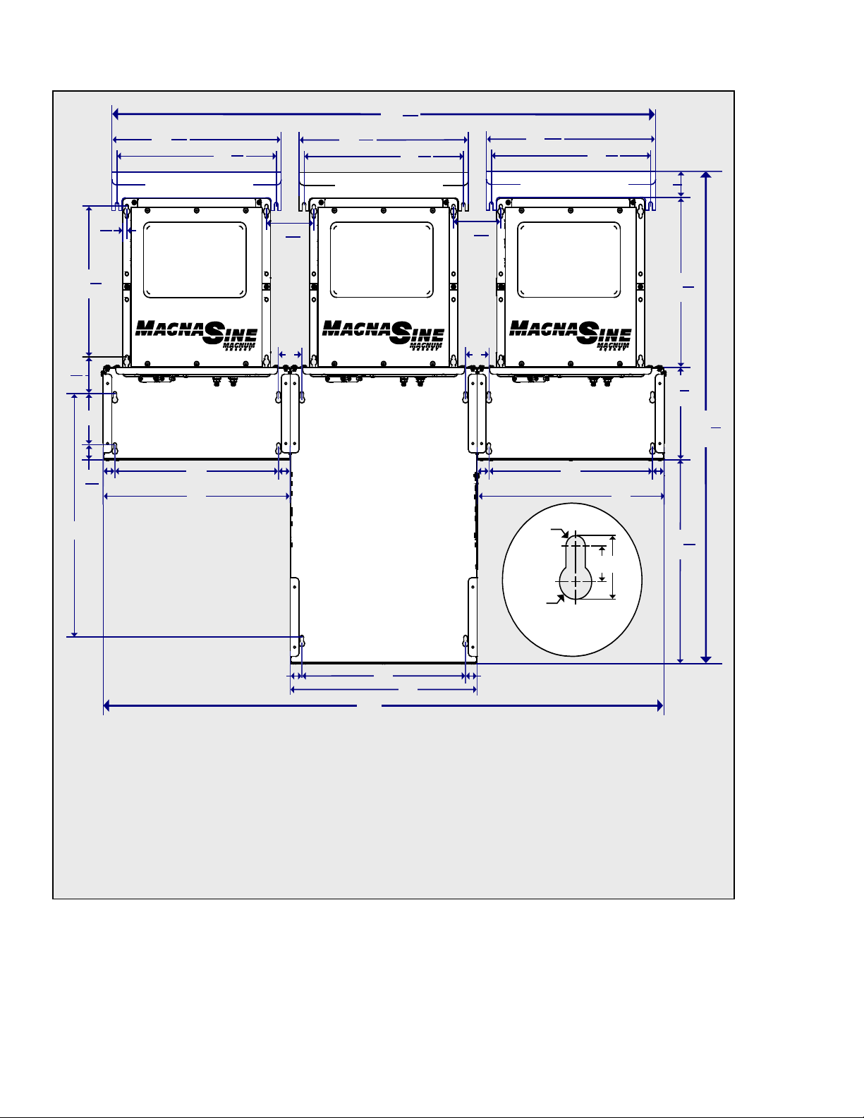
3.0 Installation
.
3
16
1
.
7
8
15
.
1
8
13
1
1
16
14
16
14
1
1
19
.
4
.
3
4
11
.
7
8
2
.
2
.
2
14
1
1
.
7
8
.
1
16
4
.
1
16
4
.
5
8
13
.
7
16
14
.
5
8
13
.
7
16
14
.
5
8
13
.
7
16
14
.
2
16
48
.
7
16
46
.
1
4
7
.
1
4
38
MP/MPX Series
Keyhole Detail
0.5
n
0.3n
0
.
5
0
.
9
INVERTER H
MAGNUM
MS-P
I
NVERTER
INVERTER H
MAGNUM
AE
MS-P
I
NVERTER
OOD
MPX LEFT SIDE
EXTENSION
MPSL/MPSH
(SINGLE E
OOD
AE
NCLOSURE)
INVERTER H
MAGNUM
MS-P
I
MPX RIGHT SIDE
EXTENSION
NVERTER
OOD
AE
Notes:
1. Lengths shown in inches.
MPSL models
2.
allow 1-2 inverters and MPSH models allow 1-3 inverters. Installations using one inverter
do not require a MPX extension, two inverters require one MPX extension, and three inverters require two
MPX extensions.
3. To meet UL regulatory requirements, an inverter hood must be installed above each Magnum inverter that
is mounted on the Magnum Panel (vertically).
Figure 3-5, System Dimensions (Single Enclosure)
© 2011 Magnum Energy, Inc.Page 23
Page 31

3.0 Installation
1
16
4
1
16
4
1
16
4
7
8
15
1
8
13
2
MPX
(Extension Box)
MPX
(Extension Box)
1
1
14
16
1
1
1 1
14
16
MPDH
Enclosure
(Dual Box)
14
16
1
1
14
16
2
2
2
5
8
13
7
16
14
5
8
13
5
8
13
5
8
13
7
16
14
7
16
14
7
16
14
3
16
1
19
4
7
8
2
1
4
38
1
4
7
5
8
60
64
7
8
3
4
11
MP/MPX Series
Keyhole Detail
0.5
n
0.3
n
0.5
0.9
INVERTER HOOD
MAGNUM
MS-PAE
INVERTER
MPX RIGHT SIDE
XTENSION
E
MAGNUM
INVERTER HOOD
INVERTER HOOD
MS-PAE
MAGNUM
MS-PAE
INVERTER
INVERTER
MPDH
ENCLOSURE
(DUAL ENCLOSURE)
MAGNUM
INVERTER HOOD
INVERTER
MS-PAE
EXTENSION
MPX LEFT SIDE
Notes:
1. Lengths shown in inches.
2. MPDH models allow 1-4 inverters. Installations using one or two inverters do not require a MPX extension, three inverters require one
MPX extension, and four inverters require two MPX extensions.
3. To meet UL regulatory requirements, an inverter hood must be installed above each Magnum inverter that is mounted on the Magnum
Panel (vertically).
Figure 3-6, System Dimensions (Dual Enclosure)
© 2011 Magnum Energy, Inc.
Page 24
Page 32

3.0 Installation
Remove the
upper four and
lower four Pan
head screws
(eight total)
to remove the
front cover.
DO NOT remove
these eight Truss
head screws to
remove the front
cover.
3.3 Preparing the MP Enclosure and Inverter
Prior to mounting any component, the installation will be easier if you prepare the MP enclosure
and the Magnum in
• Remove the MP enclosure front cover as described in Section 3.3.1.
• Remov
e the appropriate conduit knockouts as described in Section 3.3.2.
Note: It is much easier to access the enclosure sides and remove the knockouts if the enclosure
is sitting on a bench, rather than trying to remove the knockouts while the enclosure is mounted.
• Connect and separate the inverter’s AC input and output wires as described in Section 3.3.3.
When installing multiple inverters, access to the inverter’s AC terminals is limited, so take the
time to connect the wires and separate the wires prior to mounting the inverter.
3.3.1 Removing the Front Cover
To remove the front cover on each enclosure, use a T25 Torx screwdriver to unscrew the eight
upper and lower screws/w
T25 Torx drive, thread cutting screws and the washers are #10 external tooth star-washers.
The single MP enclosures (MPSL-30D, MPSL-60S, and MPSH-30D) use eight screws/washers to
hold the front cover in place, see Figure 3-8. The dual MP enclosure (MPDH-30D) also uses eight
screws/washers to hold each front cover in place (sixteen total), see Figure 3-9.
Important: On the AC side of the MPDH-30D, there is a #10-32 x3/8” Torx screw (T25 drive). It
is screwed into the right side (see Item 17, Figure 2-10a). It is used to join the two enclosures
together and must be removed prior to mounting (see Figure 3-16c).
Important: On some versions of the MP enclosure there are eight Truss head, Torx drive screws
in the middle (see Figure 3-7). DO NOT remove these middle screws to remove the front cover.
These screws are used to hold the top, middle and bottom sections of the front cover together,
and help align the knockout openings when additional breakers are installed (refer to Section A8).
verter by performing the following:
ashers as shown in Figure 3-7. The screws are #10-32 x 3/8” Pan head,
MP ENCLOSURE
Figure 3-7, Front Cover Screws to Remove
© 2011 Magnum Energy, Inc.Page 25
Page 33

3.0 Installation
#10-32
STAR
WASHERS
(X8)
#10-32 X
3/8” T25
ORX DRIVE
T
SCREWS
(X8)
Figure 3-8, Removing Front Cover - Single Enclosure
Figure 3-9, Removing Front Covers - Dual Enclosure
© 2011 Magnum Energy, Inc.
Page 26
Page 34

3.0 Installation
MP
Enclosure
MPX
Enclosure
PV Array
and
DC Loads
Charge
Controllers
Battery Cables
and
DC/System Ground
AC Source
and
AC Loads
Remote/
Router
and
Accessories
3.3.2 Planning Wire/Conduit Runs and Removing Knockouts
MP enclosure is designed to provide ample room for
The
to facilitate conduit installation for wire runs. See Figure 3-13 or 3-14 (depending on you model) to
see the size and location of these conduit knockouts. The 1/2”, 3/4”, and 1” knockouts are normally
used for the AC circuits, PV array, DC loads, and other smaller input cables. The 1 1/2” and 2”
knockouts are used to connect to the battery bank. Remove the appropriate knockout close to the
terminal where that wire connects, or whichever one works for the way your fi eld wiring comes in.
Before removing any knockout, review Figure 3-10 and think about all the wiring required and
where you are going to route the different circuits; such as:
• Wiring from the MP enclosure to the AC loads (AC sub-panel)
• Wire runs from the AC source (utility and/or a generator) to the MP enclosure
• Battery cable wiring from the battery bank to the MP enclosure
• Additional wiring from any external DC source (PV, wind, or hydro) to the MP enclosure
• Small signal wiring (remote controls, battery monitoring, auto gen starting)
• PV array and charge controller wiring
• Attaching lightning arrestors
wiring and comes standard with knockouts
Figure 3-10, Conduit/Wire Routing
© 2011 Magnum Energy, Inc.Page 27
Page 35

3.0 Installation
Inverter AC
Output Wires
Inverter AC
Input Wires
MP Enclosure
Magnum Inverter
As shown in Figure 3-11, remove the knockouts by tapping the edge with a straight bladed
scr
ewdriver and a hammer, then twist out with pliers. Ensure no debris remains inside the MP
enclosure after removing the knockouts.
Figure 3-11, Removing Knockouts
3.3.3 Connect and Separate Inverter AC Wires
ore mounting the inverter on the MP enclosure, we highly recommend using the wires provided
Bef
in the MP AC Wiring Kit (Item 6, Figures 3-1 and 3-2) and connecting them to the inverter’s AC
wiring terminals (see Figure 4-1 for MS4024 inverters, Figure 4-2 for MS-PAE Series inverters, or
refer to the inverters owner’s manual). It is possible to connect these wires after the inverter is
mounted, but space and access is limited - especially when installing multiple inverters side-byside on an MP enclosure system.
When connecting the inverter’s AC input and output wires, take time to separate the wires into
two bundles (AC input and AC output), and route each bundle thru different strain-reliefs on the
inverter as shown in Figure 3-12. This will help to ensure they are connected to the correct terminals in the MP enclosure after the inverter is mounted. Refer to Table 3-3 for information on each
wire in the AC wiring kit and where they are used.
Info: Once the AC wires are connected inside the inverter, ensure the AC wiring access
plate is reattached before mounting the inv
© 2011 Magnum Energy, Inc.
Figure 3-12, Connect and Separate Inverter AC Wires
erter on the MP enclosure.
Page 28
Page 36

3.0 Installation
.A
C
A
C
B
B
C
C
.1
4
8
B
D
.4
.1
23
.5
16
16
16
13
16
11
.5
16
11
.1
8
23
A
C
A
C
BB
FRONT
VI
EW
BOTTOM
VIEW
LEFT SIDE
VIEW
RIGHT SIDE
V
IEW
.1
16
8
.1
4
8
C
B
B B B
C
C
D D
D D
C
C
C
TOP VIEW
(WITH INVERTER
TOP PLATE)
.1
16
8
B
D
B
B
CONDUIT KNOCKOUTS:
A = ½” (x4)
B = ½” and ¾” (x12)
C = ¾” and 1” (x18)
D = 1 ½” and 2” (x6)
C
C
C
C
C
C
Figure 3-13, MPSL/MPSH Dimensions and Knockout Location/Sizes
NOTE:
ENSIONS
DIM
SHOWN IN
INCHES
© 2011 Magnum Energy, Inc.Page 29
Page 37

3.0 Installation
.A
C
A
C
B
B
C
C
.1
4
8
B
D
.1
4
23
.5
8
32
16
BOTTOM VIEW
LEFT SIDE VIEW
.1
16
8
.1
4
8
CONDUIT KNOCKOUTS:
A = ½” (x4)
B = ½” and ¾” (x16)
C = ¾” and 1” (x24)
D = 1 ½” and 2” (x10)
TOP VIEW
(WITH INVERTER
TOP PLATE)
ACA
C
BB
RIGHT SIDE VI
EW
.1
16
8
B
D
B
B
(AC SIDE) FRONT VIEW (DC SIDE)
C
B
B B B
C
C
D D
D
D
C
C
C
C
B
B B B
C
C
D D
D
D
C
C
C
.5
16
11
.1
8
23
.13
16
11
16
C
C
C
C
C
C
INCHES
SHOWN IN
DIMENSIONS
NOTE:
Figure 3-14, MPDH Dimensions and Knockout Location/Sizes
© 2011 Magnum Energy, Inc.
Page 30
Page 38

3.0 Installation
3.4 Mounting the MP/Inverter System
e careful to note the height at which you want to locate the MP and inverter to ensure you can
B
access any controls and wiring terminals. Use Figure 3-5 or 3-6 to determine the mounting keyhole
loctions, or use the base of the MP enclosure as a template to mark the mounting screw locations.
After marking the mounting screw locations, secure the MP enclosure to an appropriate solid noncombustible* vertical surface using appropriate mounting hardware. The mounting keyhole slots
on the MP enclosure will accept up to a maximum 1/4” screw/bolt.
The MP enclosure must be mounted on a vertical surface (on a wall) in an upright position to
meet regulatory requirements and to ensure the DC breakers operate properly. The surface and
mounting hardware must be capable of supporting at least three times the combined weight
of all the components mounted (i.e., MP enclosure, inverter, and any other accessories). When
considering the strength of the support surface, remember each MP enclosure with inverter can
weigh up to 120 lbs. (54 kg). Once the MP enclosure is fi rmly secured, set the Magnum inverter
into the top of the MP enclosure and secure it to the mounting surface.
If mounting the MPDH-30D, ensure the two enclosures (AC and DC sides) are mechanically and
electrically connected by screwing them together as shown in Figure 3-16c.
WARNING: The MP
to prevent personal injury.
CAUTION: When a Magnum inverter is installed vertically, the inverter hood (Item 2,
ures 3-1 and 3-2) must be installed over the top of the inverter to prevent objects
Fig
falling into the inverter’s vent openings.
Info: Magnum has two mounting backplates that provide a suitable non-combustible
rface and the required support for mounting MP enclosures, MPX enclosures, and
su
Magnum inverters together. The BP-S is the single backplate, and the BP-D is the dual
backplate. Harware to mount the MP enclosure is provide with either backplate.
* The Magnum
reach a temperature up
(90°C) and is required to be
mounted on a non-combustible
surface. A non-combustible surface
is one made of material that will not
ignite, burn, support combustion,
or release fl ammable vapors when
subjected to fi re or heat as per
the ASTM E136 standard. For the
most part, these are materials that
are largely comprised of inorganic
materials such as stone, steel, iron,
brick, tile, concrete, slate, and glass.
Common building materials such as
gypsum board as well as any paint,
wall coverings, and certainly wood
will not pass.
inverter base can
enclosure is heavy. Use proper lifting techniques during installation
to 194°F
BP-S
(SINGLE
MOUNTING
BACKPLATE)
MP SINGLE
ENCLOSURE
Figure 3-15a, Mounting the MP Single Enclosure
© 2011 Magnum Energy, Inc.Page 31
Page 39

BP-S
INGLE
(S
M
OUNTING
BACKPLATE)
MP SINGLE
ENCLOSURE
3.0 Installation
MAGNUM
I
NVERTER
Note: Prior to
mounting the inverter
connect and separate
the AC input and
output wires within the
inverter, and then route
the wiring through the
MP enclosure. Ensure
the AC access plate
is reattached to the
inverter.
,
Figure 3-15b, Mounting Inverter - MP Single Enclosure
BP-S
(SINGLE
MOUNTING
BACKPLATE)
MAGNUM
INVERTER
MP SINGLE
ENCLOSURE
INVERTER HOOD
Note: The inverter hood does not
mount to the in
must be mounted to a backplate or
wall. Mounting bolts for the hood
are included with the backplate,
otherwise the installer must supply
the bolts. The mounting slots on the
hood will accept up to a maximum
1/4” screw/bolt. The bottom edge
of the hood must be mounted fl ush
against the top of the inverter.
This is the optimal position for
minimizing the risk of objects falling
into the inverter, and at the same
time providing the airfl ow clearance
needed from the inverter’s top vents.
verter chassis, it
Figure 3-15c, Mounting Inverter Hood - MP Single Enclosure
© 2011 Magnum Energy, Inc.
Page 32
Page 40

3.0 Installation
BP-D
UAL
(D
OUNTING
M
BACKPLATE)
MPDH-30D
(DC SIDE
NCLOSURE)
E
BP-D
(DUAL M
BACKPLATE)
Figure 3-16a, Mounting the MP Dual Enclosure (DC Side)
MPDH-30D
(DC SIDE
ENCLOSURE)
OUNTING
Note: There is a #10-32
(T25 Torx drive) screw
and lock w
on the right side of the AC
side enclosure (see Item
17, Figure 2-10a).
Prior to mounting the AC
side enclosure, ensure
this Torx screw and lock
MPDH-30D
(AC SIDE
ENCLOSURE)
washer are removed.
They are used to join the
AC and DC enclosures as
shown in Figure 3-16c.
asher located
Figure 3-16b, Mounting the MP Dual Enclosure (AC Side)
© 2011 Magnum Energy, Inc.Page 33
Page 41

BP-D
(DUAL M
OUNTING
BACKPLATE)
MPDH-30D
(AC AND
DC SIDE
NCLOSURES)
E
3.0 Installation
RIGHT SIDE VIEW
Note: Screw the two enclosures
together at this location to ensure
they are electrically at the same
potential. Use the #10-32 x 3/8”
screw (T25 Torx drive) and lock
asher that is attached to the
w
AC side of the MPDH-30D at the
opposite side of this location
(see Item 17, Figure 2-10a).
Figure 3-16c, Connecting the Two Sides Together - MP Dual Enclosure
MAGNUM
PAE SERIES
INVERTER
BP-D
(DUAL M
OUNTING
BACKPLATE)
Note: Prior to mounting
, connect and
MPDH-30D
(AC AND DC SIDE
ENCLOSURES)
the inverter
separate the AC input and
output wires within the
inverter, and then route
the wiring through the MP
enclosure. Ensure the AC
access plate is reattached
to the inverter.
Figure 3-16d, Mounting First Inverter - MP Dual Enclosure
© 2011 Magnum Energy, Inc.
Page 34
Page 42

3.0 Installation
BP-D
UAL
(D
OUNTING
M
BACKPLATE)
MPDH-30D
(AC AND DC SIDE
ENCLOSURES)
Figure 3-16e, Mounting Second Inverter - MP Dual Enclosure
MS-PAE SERIES
INVERTERS
OUNTED
M
MAGNUM
AE SERIES
P
I
NVERTERS
Note: Prior to mounting
the inverter
separate the AC input and
output wires within the
inverter, and then route
the wiring through the MP
enclosure. Ensure the AC
access plate is reattached
to the inverter.
, connect and
INVERTER HOODS
INSTALLED
THE INVERTERS
OVER
Note: The inverter hood does not
mount to the in
must be mounted to a backplate or
wall. Mounting bolts for the hood are
included with the backplate, otherwise
the installer must supply the bolts. The
mounting slots on the hood will accept
up to a maximum 1/4” screw/bolt.
The bottom edge of the hood must be
mounted fl ush against the top of the
inverter. This is the optimal position for
minimizing the risk of objects falling
MPDH-30D
(AC AND DC SIDE
ENCLOSURES)
Figure 3-16f, Mounting the Inverter Hoods - MP Dual Enclosure
into the inverter, and at the same time
providing the airfl ow clearance needed
from the inverter’s top vents.
© 2011 Magnum Energy, Inc.Page 35
verter chassis, it
Page 43

3.0 Installation
3.5
Wiring the MP Enclosures
This section describes the requirements and recommendations for wiring to/from the MP enclosure.
Read all instructions before wiring the MP enclosure.
IMPORTANT: The installation of this MP enclosure/inverter system must meet all local
codes and standards and be performed by qualifi ed personnel such as licensed electricians
or Certifi ed Renewable Energy (RE) System installers.
The NEC (National Electric Code, ANSI/NFPA 70) for the United States and the CEC (Canadian
Electrical Code, CSA 22.1) for Canada provide the standards for safely wiring residential and
commercial installations. The NEC/CEC list the requirements for wire sizes, overcurrent protection,
and installation methods and requirements.
Be aware that the MP/inverter system involves power from multiple sources (inverter, generator,
utility, batteries, solar arrays, etc.) which make the wiring more hazardous and challenging.
WARNING: The AC neutral and DC negative are bonded to ground in this enclosure.
If the AC
must remove the DC and/or AC bonding inside this enclosure. Refer to Section 3.9 and
3.10 to remove the AC and/or DC ground bond connection.
WARNING: Ensure all sources of DC power (i.e., batteries, solar, wind, or hydro) and
AC power (utilit
fuses removed) before proceeding - to prevent accidental shock.
3.5.1 General Wiring Requirements
• The AC and DC wires into and out of the MP enclosure must be protected as required by code.
This can be done by using jacketed wires or by feeding the wires through conduit.
or DC circuits are already bonded to ground elsewhere in your system, you
y power or AC generator) are de-energized (i.e., breakers opened,
Info: If using a Magnum inverter, and the AC wires are individual conductors (i.e., not
cketed), the strain reliefs on the inverter can be replaced with 3/4” grommets.
ja
• Use proper clamps or other approved methods for securing the cable/conduit to the enclosure.
• The MP enclosure is specifi cally designed for both AC and DC wiring. However, where DC wiring
must cross AC or vice-versa, try to make the wires at the crossing point 90° to one another.
• Use only copper wires with a minimum rating of 150V, 75°C if only 120V AC power is being
used; or, with a minimum rating of 300V, 75°C if 120/240V AC power is being used.
• In a system where one conductor is grounded, the wire colors on the DC side and AC side
are the same. The insulation on all grounded conductors (DC negative/AC neutral) must be
white, gray, or any color except green if marked with white at each termination (marking only
allowed on 6 AWG or larger conductors). The equipment grounding conductors must be bare
(no insulation), or have green or green with yellow-striped insulation or identifi cation. The hotungrounded conductor (DC positive/AC hot) is usually red or black.
• Terminals containing more than one conductor must be listed for multiple conductors.
• The connectors or terminals used on fl exible, fi ne stranded conductors must be specifi cally
marked or labeled for use with fi ne-stranded conductors.
• The MP enclosure includes wires (along with communication cables) with insulation rated for
at least 300 volts, which allows 120/240V AC inverters to be installed. If installing a 120/240V
AC inverter, the installer must also provide wires (both power and communication) with the
insulation rated for at least 300 volts.
3.5.2 Disconnect Switch and Overcurrent Protection
For residential and commercial electrical systems, the NEC/CEC requires a disconnect switch and
vercurrent protection
o
MP enclosure provides both AC and DC circuit breakers that are used as the disconnect switch.
These circuit breakers can also be used as the overcurrent protection device when the ampacity
of the wire and its insulating material, voltage, and temperature rating are correctly sized to the
circuit breakers in your MP enclosure. Refer to the appropriate installation section (AC Wiring or
DC Wiring) to determine the minimum recommended wire size required.
for all ungrounded conductors on the AC side as well as the DC side. The
© 2011 Magnum Energy, Inc.
Page 36
Page 44

3.0 Installation
3.5.3 Wire Routing
Before
ypical routing scenarios are:
T
3.5.4 Grounding
The MP/Inverter system is intended to be installed as part of a permanently grounded electrical
s
yst
Code (CEC) CSA 22.1 in Canada, as well as all state and local code requirements. Information
and diagrams on the AC and DC ground circuits between the inverter and the MP enclosure are
provided in the AC and DC wiring sections.
Information on grounding the entire MP/inverter system to earth ground is provided in Section
3-11 and the actual system ground wiring confi guration must be determined by the installer.
3.5.5 Torque Requirements
Follow the specifi c torque recommendations in the tables below to ensure your fasteners are tightened
suffi ciently. To ensure your connections are correct, you should use an accurate, quality torque wrench.
connecting any wires, determine all wire routes to and from the MP enclosure/inverter.
•
AC input wiring from the main AC panel or from a gener
•
AC input and output from the MP enclosure to the inverter
• DC wiring from the batteries to the MP enclosure
• DC wiring from the inverter to the MP enclosure
• AC output wiring from the MP enclosure to the AC sub-panel or to dedicated circuits
• Battery Temperature Sensor cable from the inverter to the batteries
• Remote control and stacking cables to the inverter through the MP enclosure
• Ground wiring to and from the MP enclosure
em per the National Electrical Code (NEC) ANSI/NFPA 70 in the United States, Canadian Electrical
ator to the MP enclosure
CAUTION: It
torque after 5 days, and every 6 months thereafter.
CAUTION: AC and
loose and result in a fi re hazard. On the other hand, over-tightening a bolt could cause
the fastener to be snapped off.
is highly recommended to go back over all fasteners/connections and re-
DC power/wire connections that are under-torqued could become
Table 3-1, Torque Values for Dual Hole Busbars
Torque values for the dual hole busbars (i.e., AC, DC, AC NEUTRAL and GROUND busbars) -
these busbars have different torque v
Wire Size
#14 to #10 AWG
#8 AWG
#6 AWG
#4 AWG
#3 to #1/0 AWG
10-32 (Small Set-Screw) 5/16-24 (Large Set-Screw)
15 in. lbs. (1.7 N-m) 35 in. lbs. (4.0 N-m)
20 in. lbs. (2.3 N-m) 40 in. lbs. (4.5 N-m)
25 in. lbs. (2.8 N-m) 45 in. lbs. (5.1 N-m)
Table 3-2, Torque Values for
3/8-16 Bolts
1
Not Applicable 45 in. lbs. (5.1 N-m)
Not Applicable 50 in. lbs. (5.6 N-m)
alues for the small and large set-screws.
Busbar Set-Screw Size Torque Values
Table 3-3, Torque Values for Terminal
Screws on AC Input Breakers
10 to 12 ft. lbs.
(13.6 to 16.3 N-m)
Note 1 - The 3/8-16 bolts are used on the DC Shunt Busbars and DC Disconnect Breakers.
Single-pole 60A breakers 45 in. lbs. (5.1 N-m)
Double-pole 30A breakers
© 2011 Magnum Energy, Inc.Page 37
45 in. lbs. (5.1 N-m)
Page 45

3.0 Installation
3.6
This section provides information on the AC wiring inside the MP enclosure. It covers all AC wiring
to/from the inverter, from the incoming external AC source, and to the outgoing external AC
distribution panel (i.e., inverter sub-panel).
AC Wiring
3.6.1 AC Wiring Guidelines
CAUTION: Before
beginning of this manual and below to ensure a safe and long-lived system:
• Read all instructions and cautionary markings located at the beginning of this manual
and in the Pre-installation section before installing the inverter and batteries.
• AC wiring must be no less than #10 AWG (5.3 mm2) gauge copper wire and be
approved for residential wiring.
• DO NOT connect the Magnum inverter’s output to an AC power source. This could
cause severe damage to the inverter and is not covered under warranty.
WARNING: To
busbars in an AC load center (circuit breaker panel) having multi-wire branch circuits
connected. Every circuit connected to a 120V AC panel must have its own neutral;
otherwise, currents on shared neutrals will add rather than subtract, overloading the
neutral conductor.
installing
reduce the risk of fi re, do not connect a 120V AC only inverter to both
an
y AC wiring, review the safety information at the
3.6.2 AC Connections
To view the AC connection points inside the MP enclosure, review Figure 3-12 for MPSL-30D and
MPSH-30D models, Figure 3-13 for MPSL-60S models, or Figure 3-13 for MPDH-30D models.
3.6.2.1 AC Input/Output Connections
The MP enclosure provides busbars that allow the AC wiring (both inverter and external) to be
easily and permanently wired. Each busbar has dual set-screw compression terminals allowing #14
to #1/0 AWG wires using the larger set-screws and #14 to #6 AWG wires using the smaller setscrews. These busbars use slotted head set-screws and should be torqued according to Table 3-1.
The lower section of the MP enclosure provides the external AC input and output busbars. The
external AC input busbars are labeled AC HOT 1 IN, AC HOT 2 IN, AC NEUTRAL, and GROUND.
These busbars are used to wire a service/distribution panel (AC main panel) which allows the
incoming utility/AC generator input to be connected to the inverter’s input breakers. The external
AC output busbars are labeled AC HOT 1 OUT, AC HOT 2 OUT, AC NEUTRAL, and GROUND. These
busbars allow a dedicated inverter panel (AC sub-panel) to be wired between the inverter’s output
and the AC loads.
The upper section of the MP enclosure provides the inverter’s AC output busbars. The inverter
busbars are labeled INV HOT 1 OUT, INV HOT 2 OUT, AC NEUTRAL, and GROUND. These busbars
combine all the inverter outputs together when stacked for increased power capability.
Info: The busbars labeled AC NEUTRAL in the MP enclosure ARE connected together.
You do
using the Magnum MS-PAE Series inverter because the input and output neutrals are
connected together. However, using any other Magnum inverter, the input and output
neutrals are not connected, so you must connect to the inverter’s input and output
neutral terminals when wiring the neutral wires.
Info: The busbars labeled GROUND in the MP enclosure ARE connected together. You do
no
CAUTION: A neutral to ground connection is provided in the MP enclosure. If a neutral
to ground connection
the MP enclosure must be disconnected. See Section 3.9 for information to disconnect
this neutral to ground connection.
© 2011 Magnum Energy, Inc.
not need to provide both an inverter input and output neutral connection when
t need to provide both an inverter AC input and output ground connection.
is provided elsewhere in the AC system, the connection inside
Page 38
Page 46

3.0 Installation
3.6.3 Inverter AC Wires and Overcurrent Protection
d
he inverter’s AC input and output wiring must be size
T
requirements to ensure the wires’ ability to safely handle the inverter’s maximum load current. AC
wiring is required to be protected from short circuits and overloads by an overcurrent protection
device, and have a means to disconnect the AC circuits.
The wires provided in the MP AC Wire Kit (as listed in Table 3-4 for your particular MP enclosure
model) are sized to handle the inverter’s maximum load current. The MP enclosure provides AC
circuit breakers for the inverter’s AC input. These breakers are branch circuit rated and can be
used as the overcurrent protection and the AC disconnect device as long as the wires in the MP
AC Wire Kit for you particular MP enclosure (or wires with at least the same rating) are used. If
you are using other wire/circuit breaker sizes, refer to the appropriate electrical codes for proper
sizing requirements.
When parallel stacking, a Magnum MS4024PAE or MS4448PAE inverter will be used. The full AC
continuous pass-thru capacity of these inverters is 30 amps for each AC leg (AC HOT 1 or AC HOT 2),
and requires a maximum 30 amp breaker on each AC input to protect the inverter’s internal passthru relay. This correlates with the MPSL-30D, MPSH-30D, or MPDH-30D models, which include a
double-pole 30 amp input inverter breaker and requires a minimum wire size of #10 AWG1 in conduit.
When series stacking, the Magnum MS4024 inverter will be used. The AC HOT 1 and AC HOT 2 in
this inverter may be combined to obtain a 60 amps pass-thru capability. When tying the AC HOT
1 and HOT 2 together for a 60 amp continuous pass-thru capability, the AC input to the inverter
requires a 60 amp breaker. This correlates with the MPSL-60S models, which include a single 60
amp breaker for each inverter and requires a minimum wire size of #6 AWG1 in conduit.
per the local electrical safety code
Info: Additional space is provided in the MP enclosure to allow an AC breaker to be
installed for
MPX Extension Kit along with the required hardware and wires for installation.
AC Wire
Reference
INV HOT 1
IN
INV HOT 2
IN
INV NEUTRAL
IN
INV AC
GROUND
INV HOT 1
OUT
INV HOT 2
OUT
INV NEUTRAL
OUT
each additional inverter installed. These breakers are included with the
Table 3-4, MP AC Wire Kits
Separate
Wires
into:
AC
INPUT
Side
(3 wire
bundle)
AC
OUTPUT
Side
(2-3 wire
bundle)
A80-MPAC-30D-SH
(for MPSL-30D,
MPSH-30D and
MPDH-30D/AC Side)
#10 AWG Black
2
(24")
#10 AWG Red
2
(24")
NA (MS-PAE neutrals
in common)
#10 AWG Green
(24")
#10 AWG Black
w/Stripe (24”)
2
#10 AWG Red
w/Stripe (24”)
2
#10 AWG White
(24”)
A80-MPAC-60S-SH
(for MPSL
-60S)
#6 AWG Black
2
(24")
NA (provided with
MPX wire kit)
#6 AWG White
(24")
#10 AWG Green
(24")
#6 AWG Black
w/Stripe (24”)
NA (provided with
MPX wire kit)
#6 AWG White
w/Stripe (24”)
A80-MPAC-30D-LG
(for MPDH-30D/DC
Side)
#10 AWG Black
(33")
#10 AWG Red
(33")
NA (MS-PAE neutrals
in common)
#10 AWG Green
(33")
#10 AWG Black
2
w/Stripe (33”)
#10 AWG Red
w/Stripe (33”)
#10 AWG White
(33”)
2
2
2
Note 1 - This wire must be copper with a minimum rating of 300V, 75°C at an ambient temperature of 30°C.
Note 2 of the inverter AC input breakers.
This wire is longer than required to allow at least 7” to be cut and used for connecting to the bottom
© 2011 Magnum Energy, Inc.Page 39
Page 47

3.0 Installation
3.6.4 External AC Wires and Overcurrent Protection
The MP enclosure also provides a full system AC branchbypass switch. This AC breaker can be used as the overcurrent protection and disconnect for the
total current that the MP enclosure system provides to the inverter’s AC electrical sub-panel. This
is true as long as the wires routed from the MP enclosure to the inverter’s AC electrical sub-panel
are no smaller than those listed in Table 3-5 for your particular MP enclosure model. If you are
using other circuit breakers or wire sizes, refer to the appropriate electrical codes for proper sizing
requirements.
Table 3-5, Minimum AC Wire Size for AC Output Breaker
rated circuit breaker – as part of the AC
MP Enclosure
Model
-30D 60 amps #6 A
MPSL
MPSL-60S 60 amps #6 AWG (65 amps) #6 AWG (75 amps)
MPSH-30D 125 Amps #1 AWG (130 amps) #2 AWG (130 amps)
MPDH-30D 125 Amps #1 AWG (130 amps) #2 AWG (130 amps)
Note - The recommended minimum wire sizes listed above are based on using copper wire with a minimum
rating of 300V and at an ambient temperature of 30°C (86°F). If more than three cables are used together,
a cable fi ll factor de-rating may be needed. The insulation of the wire must be rated for the environmental
condition in which it will be used (i.e., for residential use, THHN is commonly used).
Note - Refer to Section 3.11 to asssit in determining the appropiate ground conductors for the AC system
based on the conductors used to/from the MP enclosure.
3.6.5
The following steps are basic guidelines for installing and connecting the AC wiring to and from the
inverter (refer
4.0 for the specifi c wiring diagrams for you particular MP enclosure.
Wiring External AC Source and AC Load Panel
. Route appropriate wires/cables from a dedicated breaker in the AC electrical main panel through
1
one of the MP enclosure’s knockouts to the AC input busbars (INPUT FROM GEN/GRID).
2. Route appropriate wires/cables (determined from Table 3-4) from the AC input busbars (OUTPUT
TO INVERTER LOADS) through another MP enclosure knockout to the AC electrical sub-panel.
AC Conductor Wiring
WARNING: To prevent electrical shock, make sure all AC power (inverter, generator,
or utility) is off before making any AC connections inside the MP enclosure.
AC Output Breaker
(part of Bypass
Assembly)
to Figures 3-17 thru 3-19 depending on your particular model). Also see Section
Conductor Temperature Rating
75°C (167°F)
WG (65 amps) #6 AWG (75 amps)
90°C (194°F)
CAUTION: When connecting external AC wires to the MP enclosure, the proper phasing
sequence (i.e.,
throughout the installation process. Refer to the system installation drawings in Section
4.0 showing the proper phasing convention. In the event the power conductors from
the external AC source (i.e., generator or grid) or the wiring into or out of the inverters
are not phased correctly, damage may occur.
Wiring Inverter AC Input/Output
1. Route the inverter’s AC input wires (previously connected in Section 3.3.3) to the top of the
inverter AC input breaker(s) inside the MP enclosure (INPUT TO INVERTER).
2. Route the inverter’s AC output wires (previously connected in Section 3.3.3) to the inverter
AC output busbars inside the MP enclosure (OUTPUT FROM INVERTER).
AC Wiring Inspection
After verifying all AC connections are correct, and all AC terminal screws are torqued correctly
(refer to Tables 3-1 to 3-3), replace the covers on the main electrical panel/sub-panel.
© 2011 Magnum Energy, Inc.
LEG 1/HOT 1 = Black, and LEG 2/Hot 2 = Red) should be maintained
Page 40
Page 48

3.0 Installation
IMPORTANT: AC - GROUND CONNECTION
(remove this green wire if the neutral is bonded
to ground either at the generator or grid source)
INV HOT 1 OUT
(from inverter’s
AC HOT 1 output)
INV HOT 2 OUT
(from inverter’s
AC HOT 2 output)
INV NEUTRAL OUT
(from inverter’s
AC NEUTRAL output)
AC NEUTRAL IN
(from neutral of
generator or grid)
AC LEG 1 IN
(from L1 side of
generator or grid)
AC LEG 2 IN
(from L2 side of
generator or grid)
GROUND BUSBAR
(inverter’s input and
output AC GROUND)
GROUND BUSBAR
(from generator/grid
ground and to AC
load panel ground)
OUTPUT FROM
I
NVERTER
INPUT TO
INVERTER
INVERTER
GROUND
OUTPUT TO
INVERTER LOADS
LOADS &
GEN/GRID
GROUND
INPUT FROM
GEN/GRID
INV NEUTRAL IN*
(to inverter’s
AC NEUTRAL input)
INV HOT 1 IN
(to inverter’s
AC HOT 1 input)
INV HOT 2 IN
(to inverter’s
AC HOT 2 input)
AC LEG 1 OUT
(to main breaker on L1
side in AC load panel)
AC LEG 2 OUT
(to main breaker on L2
side in AC load panel)
AC NEUTRAL OUT
(to NEUTRAL busbar
in AC load panel)
AC Connections (MPSL-30D and MPSH-30D Models)
* The INV NEUTRAL IN is not required if
M
S-P
AE
i
nverters are used (the neutrals
are common in these inverters).
Figure 3-17, MPSL-30D and MPSH-30D AC Wiring Connections
© 2011 Magnum Energy, Inc.Page 41
Page 49

IMPORTANT: AC - GROUND CONNECTION
(remove this green wire if the neutral is bonded
to ground either at the generator or grid source)
INV HOT 1 OUT (from AC HOT
1 output on Leg 1 inverter)
INV HOT 2 OUT (from AC HOT 2
o
u
tpu
t on Leg 2 inverter when a
second inverter (Leg 2) is installed)
INV NEUTRAL OUT [from AC
NE
UT
RAL output on Leg 1 inverter
(and neutral output to Leg 2 when
a se
cond inverter is installed)]
AC N
EUTRAL IN (from
neutral of generator or grid)
AC LEG 1 IN
(from Leg 1 side of
generator or grid)
AC LEG 2 IN (from Leg
2
s
i
de of generator or
grid when a second
inverter is installed)
GROUND BUSBAR
(inverter’s input and
output AC GROUND)
GROUND BUSBAR
(from generator/grid
ground and to AC
load panel ground)
OUT
PUT FROM
INV
ERTER
INPUT TO INVERTER
INVERTER
GROUND
OUTPUT TO
INVERTER LOADS
LOADS &
GEN/GRID
GROUND
INPUT FROM
GEN/GRID
INV NEUTRAL IN
[AC NEUTRAL to input
on Leg 1 inverter
(and input to Leg 2 when a
se
co
nd inverter installed)]
INV
HOT 1 IN
(to AC HOT 1 input
on Leg 1 inverter)
Note: If an additional
b
rea
ker is installed in this
position it becomes the
INV HOT 1 IN breaker.
The
adjacent breaker (original
HOT 1 IN) then becomes
the INV HOT 2 IN breaker.
AC LEG 1 OUT
(
t
o
main breaker on L1
side in AC load panel)
AC LEG 2 OUT
[to main breaker on L2
side in AC load panel
(from inverter’s AC
HO
T
2 OUT or Leg 2
side of generator or
grid when a second
inverter is installed)
AC NEUTRAL OUT
(to
NEUTRAL busbar
in AC load panel)
AC Connections (MPSL-60S Models)
to be added fo
r second
inverter (Leg 2)
3.0 Installation
© 2011 Magnum Energy, Inc.
Figure 3-18, MPSL-60S AC Wiring Connections
Page 42
Page 50

3.0 Installation
IMPORTANT: AC - GROUND CONNECTION
(remove this green wire if the neutral is bonded
to ground either at the generator or grid source)
AC NEUTRAL IN
(from neutral of
generator or grid)
AC LEG 1 IN
(from L
1 side of
generator or grid)
AC LEG 2 IN
(from L2 side of
generator or grid)
GROUND BUSBAR
(inverter’s input and
output AC GROUND)
GROUND BUSBARS
(from generator/grid
ground and to AC
load panel ground)
INPUT TO
INVERTERS
INVERTER
GROUND
OUTPUT TO
INVERTER LOADS
LOADS &
GEN/GRID
GROUND
INPUT FROM
GEN/GRID
AC Connections (MPDH-30D Models)
INV HOT
1 OUT
(from each inverter’s
AC HOT 1 output)
INV HOT 2 OUT
(from each inverter’s
AC HOT 2 output)
INV NEUTRAL OUT
(from each inverter’s
AC NEUTRAL output)
OUTPUT FROM
INVERTER
INV NEUTRAL IN*
(to each inverter’s
AC NEUTRAL input)
INV HOT 1 IN
(to inverter 2
AC HOT 1 input)
INV HOT 2 IN
(to inverter 2 AC
HOT 2 input)
INV HOT 1 IN
(to inverter 1
AC HOT 1 input)
INV HOT 2 IN
(to inverter 1 AC
HOT 2 input)
AC LEG 1 OUT
(to main breaker on L1
side in AC load panel)
AC LEG 2 OUT
(to main breaker on L2
side in AC load panel)
AC NEUTRAL OUT
(to NEUTRAL busbar
in AC load panel)
* The INV NEUTRAL IN is not required if
MS-PAE inverters are used (the neutrals
are common in these inverters).
Figure 3-19, MPDH-30D AC Wiring Connections
© 2011 Magnum Energy, Inc.Page 43
Page 51

3.0 Installation
3.7
DC Wiring
This section describes the DC wiring from inside the MP enclosure to the inverter, and from the
MP enclosure to the battery bank.
If installing optional DC breakers, see Section A6 in Appendix A.
Info:
3.7.1
• When the inverter is installed in a Photovoltaic System, the NEC requires that the DC circuit
conductors and overcurrent devices to the inverter be sized to carry not less than 125% of
the inverter’s maximum current rating.
• The DC positive and negative cables from the battery bank should be tied together with wire
ties or electrical tape approximately every six inches. This helps improve the surge capability
and reduces the effects of inductance, which improves the inverter waveform and reduces the
wear of the inverter’s fi lter capacitors.
• Crimped and sealed copper compression lugs with a 3/8” hole should be used to connect the
battery cables to the DC Disconnect Breaker and the DC Shunt busbar inside the MP enclosure.
• The battery bank voltage MUST match the DC voltage required by the inverter (i.e., 24-volt
battery bank for a 24-volt inverter), or the inverter may be damaged.
• The DC cables must be of a type listed for use in conduit (i.e., THHN, RHW or THW).
• To ensure the maximum performance from the inverter, all connections from the battery
bank to the inverter through the MP enclosure should be minimized, the exception is the DC
circuit breaker in the positive line and the DC shunt in the negative line. Any other additional
connection will contribute to additional voltage drops and may loosen during use.
• All wiring to the inverter and battery terminals should be checked periodically (once a month)
for proper tightness. Refer to the torque requirements in Tables 3-1 to 3-3.
• After making the battery connections and ensuring they are properly tightened, cover the
outside of the connection
jelly/anti-corrosion grease between the terminal and the battery cable.
• Ensure the color code for the DC cables/wires are correct: RED for positive (+); WHITE for
negative (-); and GREEN, GREEN with YELLOW stripe, or bare for DC equipment grounds.
DC Wiring Guidelines
WARNING:
inside the MP enclosure may be energized - DO NOT TOUCH. Disconnect all power
sources before removing the cover.
WARNING: Even
signifi cant hazards are present because of the high current available, particularly if the
battery system has a short circuit.
CAUTION: Before wiring the
of this manual and the following information to ensure a safe and long-lived system.
CAUTION: If you are using fi ne-stranded DC cables, the crimp or compression lug
used must be
Failure to use the proper terminal may cause the connection to heat-up, and it may
eventually fail or become a fi re hazard.
CAUTION: DO NOT connect the battery cables to the inverter until all wiring is
complete, and the correct DC voltage and polarity ha
During
normal
though the DC voltage/battery bank is considered “low voltage”,
specifi cally marked or labeled for use with fi ne-stranded conductors.
with petroleum jelly or an antioxidant grease/spray. Do not put
operation the terminals, busbars, and electrical components
DC cables, review the safety information at the beginning
ve been verifi ed.
© 2011 Magnum Energy, Inc.
Page 44
Page 52

3.0 Installation
3.7.2 Inverter DC Overcurrent Protection and DC Disconnect
a battery-based inverter system, the NEC/CEC assumes that each ungrounded conductor is
In
connected
and could potentially damage that conductor under fault conditions. Because of this, the NEC/
CEC requires that all ungrounded conductors in the inverter’s DC system be protected by an
overcurrent device, this can be either a circuit breaker or fuse. These breakers or fuses are not
intended to protect equipment from damage, but protect the conductor/wire from overheating
which may potentiality cause a fi re. This means the overcurrent device is required to open before
the conductor reaches its maximum current carrying capability, thereby preventing a fi re.
The NEC also requires the inverter system to have a DC disconnect switch to allow service providers
to isolate the inverter from the battery. The disconnect must be either a DC rated circuit breaker
or switch.
The MP enclosure is provided with a 250 amp UL listed, high interruption capacity, magnetichydraulic, DC rated circuit breaker. These breakers are designed to interrupt the tremendous
amount of current a battery can deliver when short-circuited. They are also specifi cally designed
to have a long enough time delay to prevent the breaker from tripping, as the inverter requires
high current levels when powering heavy loads.
If the battery cables to the inverter are no longer than fi ve feet and the wire size is a minimum
#4/0 AWG1 , the circuit breakers in the MP enclosure can provide the inverter system with both
the DC overcurrent protection device and a safety disconnect switch.
If your battery to inverter cable length is greater than fi ve feet, the DC wire size will need to be
increased. Longer distances cause an increase in resistance, which affects the performance of the
inverter.
If your battery to inverter cable size is smaller than the recommended minimum DC wire size (#4/0
AWG1), you must install a fuse/circuit breaker close to the battery bank that is compatible with this
smaller cable to protect against a potential fi re.
to
some
source
that supplies currents in excess of the ampacity rating of the conductor
CAUTION: In a
DC wire to achieve maximum effi ciency and to reduce fi re hazards associated with
overheating. Always keep your wire runs as short as practical to help prevent low
voltage shutdowns.
Info: Circuit breakers or fuses that are used on the DC side must be UL listed and DC
rated for the application.
3.8.2.1
When installing multiple inverters, the MP enclosure provides the space to add a 250 amp breaker,
for each additional inverter. These breakers — along with all the wires and hardware — are provided
with the MPX Series Extension Kit.
All MP enclosures (except for the MPSH-30D) provide space to fi eld install additional DC breakers
for use as DC input/output breakers for PV, charge controllers, or DC loads. See Section A6 for
more information.
1
Note 1 - Wire must be copper with a minimum rating of 300V, 75°C at an ambient temperature of 30°C.
Optional DC Breakers/Disconnects
low voltage/high amperage system, it is important to use the correct
© 2011 Magnum Energy, Inc.Page 45
Page 53

3.0 Installation
2
1
3
4
3
1
2
1
3
4
5
2
3.7.3 DC Hardware Connections
Do not put anything between the DC cable lug and the DC terminals (i.e., on the Inverter DC
Disconnect, DC shunt busbars,
these connections is stacked correctly. Incorrectly installed hardware causes a high resistance
connection which could lead to poor inverter performance, and may melt the cable and terminal
connections. Follow Figure 3-20 to connect the DC cables and stack the hardware correctly.
batteries, or inverter terminals). Ensure the hardware used to hold
Info: A
fter making the battery connections a
n
d ensuring they are properly torqued,
cover the outside of the connection with petroleum jelly or an antioxidant grease/spray.
Do not put jelly/anti-corrosion grease between the terminal and the battery cable.
Inverter Hardware Stack-up:
Inverter DC Terminals
INVERTER DC NEGA
POSITIVE CONNECTIONS
MAGNUM INVERTER
TIVE
AND
BATTERY POSITIVE CONNECTION TO
1
Inverter Cable Lugs
[(-) to Shunt Busbar,
2
(+) to Inverter DC Breaker]
5/16-18 Nut (Flange or Kep)
3
DO NOT Place anything between
the inverter DC terminals and the
inverter cable lugs.
DC BREAKER (BOTTOM)
Bottom of Inverter DC Breaker
Hardware Stack-up:
DC Breaker Terminal
1
Positive (+) Battery Cable Lug
2
Split-lock washer
3
Hex Bolt (3/8-16)
4
DO NOT place anything between
the DC breaker terminal and the
positive battery cable lug.
MP
ENCLOSURE
Figure 3-20, DC Hardware Connections
© 2011 Magnum Energy, Inc.
BATTERY NEGATIVE CONNECTION TO SHUNT BUSBAR (BOTTOM
Bottom of Shunt Busbar
Hardware Stack-up:
DC Shunt Busbar
1
Hex Bolt (3/8-16)
2
Negative (-) Battery Cable Lug
3
Split-lock washer
4
5/16-18 Nut
5
DO NOT place anything between
the DC Shunt busbar and the
negative battery cable lug.
)
Page 46
Page 54

3.0 Installation
3.7.4 Wiring the Battery Bank
Depending
batteries
interconnecting DC cables should be the same size and rating as those used between the battery
bank and the inverter.
Place the batteries as close as practical to the MP enclosure/inverter system, preferably in an
insulated and ventilated enclosure. Allow adequate space above the batteries to access the terminals
and vent caps (as applicable). Also allow at least 1” of space between the batteries to provide good
air fl ow. DO NOT mount the batteries directly under the MP enclosure/inverter system.
upon the voltage of the batteries used in the installation (2V, 6V, or 12V DC), the
must
be
wired
in series, parallel, or series-parallel to provide the correct voltage. The
Info: To ensure the best performance from the MP enclosure/inverter system, batteries
should
3.7.4.1 Wiring the MP enclosure to the Battery Bank/Inverter
WARNING: Ensure that
or disconnecting the battery cables, and that all sources of power (both AC and DC)
are disconnected from the inverter.
WARNING: Lethal currents
to the battery bank touch each other. During the installation and wiring process, ensure
the cable ends are insulated or covered to prevent touching/shorting the cables.
CAUTION: DO NO
accessory wiring are completed, 2) the correct DC and AC overcurrent protection have
been installed and, 3) the correct DC voltage and polarity have been verifi ed.
CAUTION: The Magnum inverter is NOT reverse polarity protected. Before making
the fi
the correct battery voltage and polarity. If the positive (+) terminal of the battery is
mistakenly connected to the negative (–) terminal of the inverter and vice versa, the
inverter will be damaged and will not be covered under warranty. Color code the cables
to avoid polarity confusion.
The following steps are basic guidelines for installing and connecting the DC wiring into and out of
the MP enclosure (refer to Figures 3-21 thru 3-23 depending on your particular model). Also see
Section 4.0 for the specifi c wiring diagrams for your particular MP enclosure.
1. Route the DC cables from inside the MP enclosure and connect them to the inverter’s DC
terminals; the negative cable (-) from the top side of the DC shunt busbar to the inverter’s DC
negative terminal, and
DC positive terminal. Be careful to observe proper polarity.
2. Route the DC cables from the battery bank — with the cables not connected to the battery —
and connect them to the MP enclosure; negative (-) to the bottom side of the DC shunt busbar,
positive (+) to the bottom side of the DC breaker. Be careful to observe proper polarity.
3. Ensure the DC wire connections (on the batteries, inverter, DC circuit breaker, and DC shunt
busbars) are fl ush on the surface of the DC terminals and the hardware used to hold these
connections are stacked correctly (see Figure 3-20); and then securely tighten these DC connections
(refer to the torque requirements in Table 3-2).
be
the same size, type, rating, and age. Do not use old or untested batteries.
of
all AC and DC breakers are switched OFF before connecting
will be present if the positive and negative cables attached
T connect the DC wires to the battery bank until: 1) all DC, AC, and
nal DC connection from the batteries to the inverter, use a voltmeter to verify
the positive cable (+) from the top side of the DC breaker to the inverter’s
CAUTION: Only after
should the DC circuit breaker be closed to provide power to the inverter.
4. Route an appropriately sized DC grounding wire (green or bare wire) from the inverter’s DC
equipment ground terminal and from the battery bank enclosure to the DC GROUND busbar in the
MP enclosure. Refer to Section 3.11 for grounding information and sizing the DC ground wires.
the entire installation is complete and all connections are verifi ed
© 2011 Magnum Energy, Inc.Page 47
Page 55

3.0 Installation
DC8A
DC6
DC8B
DC1
DC2
DC4
DC7
DC5
DC3
3.7.5 DC Wiring Connection Points
Figures 3-21 thru 3-23 show the connection points for the DC wiring inside the MP enclosures.
DC NEGA
ONNECTION
C
ADDITIONAL INVERTER
DC NEGA
NEGATIVE
ADDITIONAL BATTERY BANK
NEGATIVE
DC EQUIPMENT
GROUNDING
CONNECTION
TIVE CABLE
TO INVERTER
TIVE
ABLE CONNECTION
C
BATTERY BANK
CABLE CONNECTION
CABLE CONNECTION
DC POSITIVE
ONNECTION TO INVERTER
C
C
ABLE
BATTERY BANK
POSITIVE C
DC GROUNDING
ELECTRODE
CONNECTIONS
DC CONNECTIONS
UNDER
(
DISCONNECT)
ABLE CONNECTION
THE
DC
DC1
DC2
DC3
DC4
DC5
DC6
DC7
DC8
Figure 3-21, DC Wiring Connection Points for MPSL Models
Inverter’s DC Negative Cable Connection - Cable connection to Magnum inverter’s
DC negative terminal. Electrically connected to the top of the DC shunt.
Inverter’s DC Positive Cable Connection - Cable connection to Magnum inverter’s
DC positive terminal. Electrically connected to the top of the inverter’s DC disconnect.
Additional Inverter DC Negative Cable Connection - Provided so that as more inverter’s
are added, cables can be added and connected to the inverter’s DC negative terminals.
Battery Bank Negative Cable Connection - DC Negative Busbar connection (bottom
connection of DC shunt); connects cables to the battery bank’s negative terminal.
Additional Battery Bank Negative Cable Connection - Provided to connect
additional cables to the battery bank’s negative terminal when additional Magnum
inverters are installed.
Battery Bank Positive Cable Connection - Bottom of the inverter’s DC disconnect
breaker; connects the battery cable to the battery bank’s positive terminal.
DC Equipment Grounding Connection - This busbar is used as the common DC
equipment ground point for all DC equipment connected in the MP/inverter system.
DC Grounding Electrode Connections - These are the connection points for the MP/
inverter system to the DC grounding electrode. Use DC8A for #6 to #1/0 AWG wires,
and DC8B for greater than #1/0 AWG wires.
© 2011 Magnum Energy, Inc.
Page 48
Page 56

3.0 Installation
DC8A
DC6
DC8B
DC1 DC2
DC4
DC7
DC5
DC3
DC NEGA
ONNECTION
C
ADDITIONAL INVERTER DC
N
EGA
NEGATIVE
ADDITIONAL BATTERY BANK
NEGATIVE
DC EQUIPMENT
GROUNDING
CONNECTION
TIVE CABLE
TO INVERTER
TIVE
CABLE CONNECTIONS
BATTERY BANK
CABLE CONNECTION
CABLE CONNECTIONS
DC POSITIVE
ONNECTION TO INVERTER
C
C
ABLE
POSITIVE C
DC GROUNDING
ELECTRODE
CONNECTIONS
BATTERY BANK
ABLE CONNECTION
DC CONNECTIONS
(
THE
UNDER
DISCONNECT)
DC
DC1
DC2
DC3
DC4
DC5
DC6
DC7
DC8
Figure 3-22, DC Wiring Connection Points for MPSH-30D
Inverter’s DC Negative Cable Connection - Cable connection to Magnum inverter’s
DC negative terminal. Electrically connected to the top of the DC shunt.
Inverter’s DC Positive Cable Connection - Cable connection to Magnum inverter’s
DC positive terminal. Electrically connected to the top of the inverter’s DC disconnect.
Additional Inverter DC Negative Cable Connections - Provided so that as more inverter’s are added, cables can be added and connected to the inverter’s DC negative terminals.
Battery Bank Negative Cable Connection - DC Negative Busbar connection (bottom
connection of DC shunt); connects cables to the battery bank’s negative terminal.
Additional Battery Bank Negative Cable Connections - Provided to connect
additional cables to the battery bank’s negative terminal when additional Magnum
inverters are installed.
Battery Bank Positive Cable Connection - Bottom of the inverter’s DC disconnect
breaker; connects the battery cable to the battery bank’s positive terminal.
DC Equipment Grounding Connection - This busbar is used as the common DC
equipment ground point for all DC equipment connected in the MP/inverter system.
DC Grounding Electrode Connections - These are the connection points for the MP/
inverter system to the DC grounding electrode. Use DC8A for #6 to #1/0 AWG wires,
and DC8B for greater than #1/0 AWG wires.
© 2011 Magnum Energy, Inc.Page 49
Page 57

3.0 Installation
DC8A
DC6
DC1
DC2
DC4
DC7
DC5
DC3
DC8B
INVERTER DC CONNECTIONS
ADDITIONAL INVERTER DC
N
EGA
BATTERY BANK
NEGATIVE
CONNECTIONS
POSITIVE C
DC EQUIPMENT
GROUNDING
CONNECTIONS
AC SIDE)
(IN
TIVE
CABLE CONNECTIONS
CABLE
BATTERY BANK
ABLE CONNECTIONS
DC POSITIVE
C
ABLE
CONNECTIONS
TO INVERTER
DC CONNECTIONS
UNDER
(
THE
NEGATIVE CABLE
ELECTRODE CONNECTIONS
DC NEGA
C
ABLE
ONNECTIONS
C
TO INVERTER
DC DISCONNECT)
ADDITIONAL
Y BANK
BATTER
CONNECTIONS
DC GROUNDING
TIVE
Figure 3-23, DC Wiring Connection Points for MPDH-30D (DC Side)
DC1
DC2
DC3
DC4
DC5
DC6
DC7
DC8
Inverter’s DC Negative Cable Connections - Cable connections to Magnum inverter’s
DC negative terminal. Electrically connected to the top of the DC shunt.
Inverter’s DC Positive Cable Connections - Cable connections to Magnum inverter’s
DC positive terminal. Electrically connected to the top of the inverter’s DC disconnect.
Additional Inverter DC Negative Cable Connections - Provided so that as more inverter’s are added, cables can be added and connected to the inverter’s DC negative terminals.
Battery Bank Negative Cable Connections - DC negative busbar connections (bottom
connection of DC shunt); connect cables to the battery bank’s negative terminal.
Additional Battery Bank Negative Cable Connections - Provided to connect
additional cables to the battery bank’s negative terminal when additional Magnum
inverters are installed.
Battery Bank Positive Cable Connections - Bottom of the inverter’s DC disconnect
breaker; connect battery cables to the battery bank’s positive terminal.
DC Equipment Grounding Connections - These busbars are used as the common
DC equipment ground point for all DC equipment connected in the MP/inverter system.
DC Grounding Electrode Connections - These are the connection points for the MP/
inverter system to the DC grounding electrode. Use DC8A for #6 to #1/0 AWG wires,
and DC8B for greater than #1/0 AWG wires.
© 2011 Magnum Energy, Inc.
Page 50
Page 58

3.0 Installation
3.8 Wiring Accessories
NEC/CEC requires the insulation of all conductors inside the MP enclosure to be rated for the
The
highest voltage present. The MP enclosure is designed to work with inverters that provide 120/240V
AC (i.e., MS-PAE Series), therefore, the voltage rating of the communications cables inside the MP
enclosure must be rated for 300 volts or higher to be code compliant.
With the purchase of the MP enclosure, Magnum has included three six-foot, yellow communication
cables with 300-volt rated insulation. These communications cables — shown below — are provided
to make the connections between Magnum inverters and any accessories easier and code compliant.
Figure 3-27 shows a basic drawing for connecting accessories into and out of the MP enclosure.
Refer to Section 4.0 for specifi c communications wiring diagrams for your particular MP enclosure.
Info: These cables carry less than 30 volts and are thus considered a “limited energy
circuit”, which is normally not required to be installed in conduit.
F
igure 3-24 shows the ‘REMOTE’ cable. It allows
a remote control — such as the ME-RC (Remote
Control), ME-ARC (Advance Remote Control), or
ME-RTR (Router) — to be connected to the inverter
through the MP enclosure. This cable is a 6’ (1.83 m),
4-conductor, telephone-type cable with a RJ14 (m)
connector and a blue REMOTE label on each end. One
end of this cable is connected to the remote, and the
other end is routed inside the MP enclosure and then
connected to the inverter’s REMOTE port.
Figure 3-24, REMOTE Communication Cable (300V Rated)
Figure 3-25 shows
Magnum accessories — like the ME-AGS-N (Auto
Generator Start - Network) or ME-BMK-NS (Battery
Monitor - No Shunt) — to be connected to the inverter
through the MP enclosure. This cable is a 6’ (1.83
m), 4-conductor, telephone-type with a RJ14 (m)
connector and a green NETWORK label on each end.
One end of this cable is connected to the accessory,
and the other end is routed inside the MP enclosure
and then connected to the inverter’s NETWORK port.
the ‘NETWORK’ cable. It allows
Figure 3-25, NETWORK Communication Cable (300V Rated)
Figure 3-26 shows
the Magnum Battery Temperature Sensor (BTS) to be
connected to the inverter through the MP enclosure.
This is a 6’ (1.83 m), 4-conductor, telephone-type
cable with a RJ14 (m) connector on one end and
a RJ14 (f) plug on the opposite end. The female
plug connects to the ME-BTS (Battery Temperature
Sensor). After connecting to the ME-BTS, this
extension cable is routed inside the MP enclosure and
connects to the inverter’s BTS port.
the ‘EXTENSION’ cable. It allows
Figure 3-26, Extension Cable (300V Rated)
© 2011 Magnum Energy, Inc.Page 51
Page 59

BTS
Extension Cable (300 volt rated)
ME-BTS
REMOTE
Communication Cable
(300 volt rated)
REMOTE
REMOTE
NETWORK
NETWORK
NETWORK
Communication Cable
(300 volt rated)
ME-AGS-N
ME-RTR
(ME-RC or ME-ARC)
3.0 Installation
Figure 3-27, Accessory Wiring Using 300 Volt Communications Cables
© 2011 Magnum Energy, Inc.
Page 52
Page 60

3.0 Installation
3.9 Removing the NEUTRAL-GROUND Wire
The MP enclosure
of ground for the AC system. The neutral to ground connection is done by connecting a green wire
(Item 19, in Figures 2-7 and 2-8, Item 23 in Figure 2-9, or Item 13 in Figure 2-10a, depending on
your MP model) between the AC NEUTRAL busbar and the GROUND busbar inside the MP enclosure.
In installations where the MP enclosure is powered from utility power or large permanently installed
generator systems, the AC neutral to ground connection is normally provided inside the main AC
electrical distribution panel. In these installations, the factory-installed NEUTRAL-GROUND wire in
the MP enclosure must be removed to prevent multiple neutral to ground connections.
To remove the NEUTRAL-GROUND wire:
1. See Figure 3-28 below to help you locate the green wire with the NEUTRAL-GROUND CONNECTION label inside your MP enclosure.
2. Remove this green wire by loosening the screws on the AC NEUTRAL busbar and the GROUND
busbar.
3. After this wire is removed, tighten the loose screws back into the busbars to prevent them
from being lost.
is shipped with the AC neutral connected to ground to provide the single point
NEUTRAL-GROUND
Wire inside
MPSL/MPSH
AC
NEUTRAL
Busbar
NEUTRAL-
UND
GRO
CONNECTION
(green wire)
NEUTRAL-GROUND Wire
inside MPDH (AC Side)
GROUND
Busbar
Figure 3-28, Removing the NEUTRAL-GROUND Wire
© 2011 Magnum Energy, Inc.Page 53
Page 61

3.0 Installation
3.10 Removing the NEGATIVE-GROUND Busbar
The MP enclosure
of ground for the DC system. This negative to ground connection is done by connecting the DC
Shunt (battery negative connection point) to the DC Ground Stud using the NEGATIVE-GROUND
busbar. If a negative to ground connection is made elsewhere in the DC system — either at the
battery terminal, inside a charge controller, or if you are installing a PV-Ground Fault Protection (PVGFP) device — this busbar must be removed to prevent multiple negative to ground connections.
Step 1, Remove Plate and Locate NEG-GND Busbar
is shipped with the DC Negative connected to Ground to provide the single point
Follow the steps below to remove the
NEG
ATIVE-GROUND busbar (refer to
NEGATIVE-
GROUND
busbar
the diagram to the left to help locate the
components discussed):
1. Remove the Shunt Access Plate on
the right side of the MP enclosure.
DC
Ground
Stud
Locate the NEGATIVE-GROUND busbar (Item 27, in Figure 2-9; or Item
29, in Figures 2-7, 2-8 or 2-10b - depending on your MP model) attached
to the DC Shunt.
DC
Shunt
2. Remove the 5/16” fl ange nut (1/2”
wrench) holding the busbar to the
DC Ground Stud and then remove
the 3/8” brass bolt and washer (9/16”
wrench) from the top terminal of the
DC Shunt.
3. Remove the NEGATIVE-GROUND
busbar.
4. Reattach the fl ange nut on the DC
Shunt
Access Plate
Ground Stud and the brass bolt/
washer back onto the DC Shunt.
Ensure the hardware on the top ter-
MP Enclosure
minal of the DC Shunt is stacked/
reattached and torqued correctly.
Note: The DC Shunt hardware is
shown correctly stacked in the Step
4 diagram below.
Step 2, Remove
Shunt Hardware
Figure 3-29, Removing the NEGATIVE-GROUND Busbar
© 2011 Magnum Energy, Inc.
Step 3, Remove the
NEGATIVE-GROUND Busbar
Step 4, Reattach
Shunt Hardware
Page 54
Page 62

3.0 Installation
DC
S
OURCE
MAIN AC PANEL
.HOT1
.NEUT
.GND
.HOT2
.DC SIDE
.AC SIDE
MP ENCLOSURE
or
AC
SOURCE
AC and DC sides shared
DC side dedicated
AC side dedicated
or
or
DC Electrical
System
AC Electrical
System
Grounding System
.GND
.POS
.NEG
HOT 1
HOT 2
NEUT
GBB
SBJ
GEC-DC
GE
GE
GEC-AC
GE
GBB
SBJ
MAGNUM
I
NVERTER
BAT
BAT
or
GC-DCGC-AC
EGC
EGC
3.11 MP/Inverter System Grounding
MP/inverter system uses both AC and DC electrical systems, therefore each electrical system
The
is required to be properly connected to a permanent, common “ground” or “earth” reference. A
MP/inverter system that is properly grounded limits the risk of electrical shock, reduces radio
frequency noise, and minimizes excessive surge voltages induced by lightning. To understand
how the conductors in the electrical circuit will be connected to the system ground, the following
terms should be understood (also refer to Figure 3-30):
• Grounded Conductor (GC): The wire/cable in the electrical system that normally carries current
(usually the AC neutral and/or the DC negative), and is intentionally connected or “bonded” to
the ground system. This wire, or the ends of this wire, must be colored white or gray.
• Equipment Grounding Conductor (EGC): A wire/cable that does not normally carry current
and is used to connect the exposed metal parts of equipment — that might be accidentally
energized — to the grounding electrode system or to the grounded conductor. This wire, or the
ends of this wire, must be green or green with a yellow stripe; or, this wire can be bare copper.
• Grounding Electrode Conductor (GEC): The wire/cable that does not normally carry current,
and connects the grounded conductor and/or the equipment grounding conductor at the service
equipment (i.e., equipment delivering the electrical energy) to the grounding electrode.
• Grounding Electrode (GE): A ground rod or conducting element that establishes an electrical
connection to the earth or common ground reference.
• System Bonding Jumper (SBJ): The connection between the grounded circuit conductor in
the electrical system and the equipment grounding conductor at a separately derived system.
There are two types of grounding — equipment grounding and system grounding.
The exposed metal parts of the equipment in the system usually don’t carry electricity. However, if
the exposed metal becomes electrifi ed by a live wire, a person touching this live part could complete
the electrical circuit and receive a shock. Equipment grounding prevents shock by connecting all
the exposed metal parts of equipment (via Equipment Grounding Conductors - EGC) together
at a common ground point (Ground BusBar - GBB). This common ground point — installed in
the service disconnect panel for each electrical system (AC and DC) — is then connected (via
Grounding Electrode Conductor - GEC) to the common ground reference, such as a ground rod
(Grounding Electrode - GE). This connection to earth is made at only one point in each electrical
system; otherwise, parallel paths will exist for the currents to fl ow. These parallel current paths
would represent a safety hazard and are not allowed in installations wired per the NEC/CEC.
System grounding takes one of the current-carrying conductors (Grounded Conductor - GC) and
attaches it to the common ground point (Ground BusBar - GBB), usually by a System Bonding
Jumper (SBJ) in each electrical service disconnect panel. On the AC side, that is the neutral
conductor (GC-AC); on the DC side, it’s the negative conductor (GC-DC). The closer the grounding
connection is to the source, the better the protection from high voltage surges due to lightning.
Figure 3-30, Grounding System for Inverter with MP Enclosure
© 2011 Magnum Energy, Inc.Page 55
Page 63

3.0 Installation
DC
S
OURCE
MAIN AC PANEL
.HOT 1
.NEUT
.GND
.HOT 2
.DC SIDE
.AC SIDE
MP ENCLOSURE
AC
SOURCE
DC side dedicated
DC Electrical
Syst
em
AC Electrical
System
Grounding System
.GND
.POS
.NEG
GBB
SBJ
GEC-DC
GE
GBB
SBJ
MAGNUM
I
NVERTER
GEC-AC
GC-DC
BAT
GC-AC
HOT 1
HOT 2
NEUT
BAT
EGC
EGC
3.11.1 Sizing the Grounding Electrode Conductors
AC Side
the largest ungrounded conductor feeding the AC load center. One #8 AWG (8.4 mm2) copper
conductor will serve as an AC grounding electrode conductor for AC power conductors smaller than
and including #2 AWG (33.6 mm2) copper. See Table 3-6 for additional values.
- The size of the AC Grounding Electrode Conductor (GEC–AC) depends on the size of
Table 3-6, AC Grounding Electrode Conductor Sizing
Size of Largest Ungrounded
Conductor
#2 A
WG or smaller
#1 to #1/0 A
#2/0 or #3/0 AWG
Over #3/0 AWG
through 350 kcmil
WG
Minimum Size of Grounding
Electrode Conductor
WG (8.4 mm
#8 A
#6 AWG (13.3 mm
#4 AWG (21.1 mm
#2 AWG (33.6 mm
2
)
2
)
2
)
2
)
DC Side - To size the DC grounding electrode conductor, fi rst determine which one of the following
three methods will be used to connect the DC and AC grounding points in the inverter’s two
electrical systems (AC and DC) to the common “earth” ground.
Info: There are many variables to consider when choosing the size of the DC grounding
electrode conductor
. The MP enclosure provides the means to ground both the AC and
DC to a single ground, and when feasible, the Single Connection to Ground (Method 1)
is recommended. With this method the NEC allows a #6 AWG wire, which makes the
overall installation simpler and less costly.
1. Single Connection to Ground (Method 1): The AC Grounding Electrode Conductor
(GEC–AC) is bonded to the DC ground point and the DC Grounding Electrode Conductor (GEC–DC)
is the only connection to the grounding electrode, which must be a rod, pipe, or plate electrode
(see Figure 3-31).
Normally the size of the DC grounding electrode conductor must be no less than the size of the
battery bank’s negative cable. However, in this method, since there is only one connection to the
ground rod the NEC allows an exception. The DC grounding electrode conductor is not required
to be larger than #6 AWG (13 mm2) copper. The reasoning for allowing this smaller grounding
electrode conductor is that it is only required to stabilize the system voltage with respect to earth,
and the other properly-sized conductors in each electrical system will safely carry any fault currents
if they occur.
© 2011 Magnum Energy, Inc.
Figure 3-31, Single Connection to DC Ground Rod (Method 1)
Page 56
Page 64

3.0 Installation
DC
SOURCE
MAIN AC PANEL
.HOT 1
.NEUT
.GND
.HOT 2
.DC SIDE
.AC SIDE
MP ENCLOSURE
AC
SOURCE
AC and DC sides shared
DC Electrical
System
AC Electrical
System
Grounding System
.GND
.POS
.NEG
GBB
GE
GEC-AC
GBB
MAGNUM
I
NVERTER
GEC-DC
SBJ
SBJ
GC-DC
GC-AC
HOT 1
HOT 2
NEUT
BAT
BAT
EGC
EGC
DC
SOURCE
MAIN AC PANEL
.HOT 1
.NEUT
.GND
.HOT 2
.DC SIDE
.AC SIDE
MP ENCLOSURE
AC
SOURCE
DC side dedicated
AC side dedicated
DC Electrical
System
AC Electrical
System
Grounding System
.GND
.POS
.NEG
GBB
GE
GEC-AC
GE
GBB
MAGNUM
I
NVERTER
GEC-DC
BC
SBJ
SBJ
GC-DC
GC-AC
BAT
BAT
HOT 1
HOT 2
NEUT
EGC
EGC
2. Multiple Connections to Ground - Single Electrode (Method 2): When the
AC and
DC service panels are near each other, then the AC Grounding Electrode Conductor (GEC–AC) and
DC Grounding Electrode Conductor (GEC–DC) can be connected to a single grounding electrode
(see Figure 3-32). In this method — since there are multiple connections to the DC grounding
electrode — the size of the DC grounding electrode conductor cannot be smaller than the largest
conductor in the DC system (usually the battery-to-inverter cable).
Figure 3-32, Multiple Connections to DC Ground Rod (Method 2)
3. Multiple Connections to Ground - Multiple Electrodes (Method 3): This method
a separate grounding electrode for the DC system and the AC system (see Figure 3-33). In this
method — since there are multiple connections to the DC Grounding Electrode (GEC–DC) — the
size of the DC grounding electrode conductor cannot be smaller than the largest conductor in the
DC system (usually the battery-to-inverter cable).
The DC Grounding Electrode (GE–DC) must be bonded to the AC Grounding Electrode (GE–AC)
to make a grounding electrode system; this Bonding Conductor (BC) cannot be smaller than the
largest grounding electrode conductor, either AC or DC.
Figure 3-33, Multiple Connections to DC Ground Rod (Method 3)
© 2011 Magnum Energy, Inc.Page 57
uses
Page 65

3.0 Installation
3.11.2
Equipment Grounding Conductor
The MP enclosure and all other non-current carrying exposed metal surfaces in the entire electrical
yst
em that may be accidentally energized must be grounded. The equipment-grounding conductor
s
must be sized to safely carry the maximum ground-fault current likely to be imposed on it from
where a ground-fault may occur.
AC Side - When the inverter’s AC input circuit breaker provided in the MP enclosure is being
used as the inverter’s AC overcurrent protection device, the AC Equipment Grounding Conductor
(EGC–AC) for the inverter is based on the AC breaker size provided (#10 AWG for all MP models).
Connect the AC equipment-grounding conductor from the inverter’s AC ground connection to the
AC Ground Busbar (GBB) in the MP enclosure (Item 25 in Figure 2-7 or 2-8, Item 22 in Figure
2-9, or Item 16 in Figure 2-10a - depending on your MP model).
DC Side - When the DC circuit breaker provided in the MP enclosure is being used as the inverter’s
DC overcurrent protection device, the DC Equipment Grounding Conductor (EGC–DC) for the
inverter should be #4 AWG, which is based on the 250 amp DC breaker size provided. Connect the
DC equipment-grounding conductor from the inverter’s DC ground connection to the DC Ground
Busbar (GBB) in the MP enclosure (Item 27 in Figures 2-7 or 2-8, Item 25 in Figure 2-9, or Item
26 in Figure 2-10b - depending on your MP model).
If you are using AC or DC overcurrent protection that is different than that provided in the MP
enclosure or installing optional DC breakers inside the MP enclosure, in accordance with the NEC/
CEC you must determine your equipment-grounding conductors based on the ampere rating of
the overcurrent device protecting the circuit conductors. Use Table 3-7 to help determine the
equipment-grounding conductor. If the circuit conductors are oversized to compensate for voltage
drop, the equipment-grounding conductor must also be oversized proportionally.
Table 3-7, Equipment Grounding Conductor Sizing
Rating of Overcurrent Device Minimum Size of Copper Ground Wire
15 amp #14 AWG
20 amp #12 AWG
30 - 60 amp #10 A
100 amp #8 AWG
200 amp #6 AWG
300 amp #4 AWG
400 amp #3 AWG
WG
3.11.3 System Bonding Jumper
The MP enclosure provides the single point of ground [System Bonding Jumper (SBJ)] for the AC
DC system. If
and
in an off-grid system) and there is no other connection to ground from neutral (in the AC system)
or negative (in the DC system), then leave the ground bond connections in place. Remove any
other neutral to ground connection in the AC system, such as in other electrical sub-panels; or,
any negative to ground connection in the DC system.
For utility connected systems where the neutral and ground are already bonded in the main utility
circuit breaker box (AC distribution panel), the NEUTRAL-GROUND wire MUST BE REMOVED from
the MP enclosure. See Section 3.9 to remove this neutral to ground connection.
Info: Inverters and portable generators that have electrical outlets usually have the
neutral
to be connected to the MP/inverter system as they would fi rst need to be modifi ed to
separate the neutral and ground bonding internally.
For systems or devices that connect the DC negative to ground independently (i.e., separate DC
main electrical distribution panel or PV-GFP device), the NEGATIVE-GROUND busbar (Item 27 in
Figure 2-9, or Item 29 in Figures 2-7, 2-8 and 2-10b - depending on your MP model) MUST BE
REMOVED inside the MP enclosure. See Section 3.10 to remove this negative to ground connection.
the MP enclosure is the central connection point for all ground wiring (usually
and ground bonded internally. These types of devices are not recommended
© 2011 Magnum Energy, Inc.
Page 58
Page 66

3.0 Installation
3.12 Installation Checklist
Use this checklist
have been completed before proceeding with the functional test.
Mounting
❐ The MP enclosure/inverter system is securely mounted in a clean, dry, and ventilated area.
❐ The MP enclosure/inverter system is not mounted in the same enclosure as maintenance-free
or vented type batteries.
❐ The MP enclosure is mounted in a ‘vertical only’ position.
❐ There is adequate clearance to access the front and to view/adjust the remote (if installed).
DC Wiring
Inverter Side:
❐ The inverter is correctly placed on the MP enclosure with the inverter’s DC terminals attached
to the inverter DC negative and positiv
Battery Bank Side:
❐ An appropriately sized DC cable is routed from the positive (+) battery terminal and attached
to the bottom terminal of the inverter DC disconnect breaker inside the MP enclosure.
❐ An appropriately sized DC cable is routed from the negative (-) battery terminal and attached
to the busbar which is connected to the bottom terminal of the DC shunt inside the MP enclosure.
❐ The DC hardware is stacked correctly (refer to Figure 3-20).
❐ The DC cable connections are torqued correctly (refer to Tables 3-1 to 3-3).
AC Wiring
❐ To Inverter: The AC wires are appropriately sized and routed from the inverter AC Input breaker(s)
inside MP enclosure to the inverter’s AC input terminals.
❐ From Inverter: The AC wires are appropriately sized and routed from the inverter’s AC output
terminals to the AC output busbars (INV HOT 1 OUT, INV HOT 2 OUT, AC NEUTRAL and GROUND)
inside MP enclosure.
❐ To Main AC Electrical Panel: The AC wires are appropriately sized and are routed from the AC
input busbars (AC LEG 1 IN, AC LEG 2 IN, AC NEUTRAL and GROUND) inside MP enclosure to the
circuit breaker in the main AC electrical panel (i.e., main panel) powered by the generator or grid.
Use Table 3-4 to determine the AC wire size to/from the MP enclosure.
❐ To Inverter AC Load Panel: The AC wires are appropriately sized and routed from the AC output
busbars (AC LEG 1 OUT, AC LEG 2 OUT, AC NEUTRAL and GROUND) inside MP enclosure to the
main circuit breaker in the electrical panel powered by the inverter (i.e., sub-panel). Use Table
3-4 to determine the AC wire size to/from the MP enclosure.
❐ AC wires connected to the busbars/circuit breakers are torqued correctly (see Tables 3-1 to 3-3).
Grounding
❐ There is only one bonding connection to ground for the DC electrical system (negative to ground)
and one bonding connection to ground for the AC electrical system (neutral to ground). These
bonding connections may be connected to the same grounding electrode system (ground rod). If
separate electrodes are used, they must be bonded together.
❐ The exposed metal parts of equipment are properly grounded.
❐ Equipment grounding conductors are properly sized.
Electrical Connections
❐ Connectors are listed for the intended use and environment (inside, outside, wet, etc.).
❐ Pressure/screw terminals tightened to the recommended torque specifi cation.
❐ Terminals containing more than one conductor are listed for multiple conductors.
❐ Connectors using fl exible, fi ne-stranded conductors are listed for use with such conductors.
❐ All electrical terminal connections in the inverter are re-torqued to tighten any connections that
may have loosened since the initial installation.
as a fi nal review to ensure all essential steps of the MP enclosures installation
e cables inside the MP enclosure.
© 2011 Magnum Energy, Inc.Page 59
Page 67

3.0 Installation
Conductors and General Wiring Methods
❐ Conductors are rated for the application and the environment.
❐ Standard building-
Note: Welding, marine, locomotive (DLO), and auto battery cables don’t meet NEC/CEC
requirements. Flexible RHW or THW cables are available, but these cables require very limited,
specially listed terminals. When the battery conductors leave the battery enclosure, the conductors
must be of a type listed for use in conduit (RHW or THW).
❐ The DC and AC color codes for the ground conductors are the same – grounded conductors are
white and equipment-grounding conductors are green, green/yellow, or bare (no insulation).
❐ All wiring insulation have a minimum rating of 150V, 75°C when using only 120V AC power/
inverter; or, with a minimum rating of 300V, 75°C when using 120/240V AC power/inverter.
❐ Strain reliefs/cable clamps or conduit are used on all cables and cords.
❐ Conductors between the inverter and battery bank are installed in conduit.
❐ No multi-wire branch circuits when single, 120V AC inverters are connected to 120/240V AC
load centers.
Note: A multi-wire branch circuit is a three-wire circuit with a shared neutral for two, 120V AC
branch circuits.
Overcurrent Protection
❐ Properly sized and rated disconnects and overcurrent devices are used in the ungrounded
conductors in each circuit (AC and DC).
❐ Overcurrent devices in the DC circuits are listed for DC operation.
❐ DC overcurrent protection is provided at the batteries when they are located in a separate room,
or more than fi ve feet away from the MP enclosure.
❐ The DC overcurrent protection device and battery cables to the inverter are sized for the inverter’s
DC input current.
Note: Inverter’s DC input current is calculated using rated AC output in watts, divided by lowest
battery voltage, divided by inverter effi ciency at that power level.
❐ When the inverter DC disconnect breaker inside the MP enclosure is not used as the DC overcurrent
device, high interrupt, listed, DC-rated fuses or circuit breakers must be used in the battery cable
circuits.
wire conductors and appropriate wiring methods are used.
Batteries
❐ Battery terminals and other live parts are guarded, and adequate working space around the
battery bank is provided.
❐ Batteries are installed in well-vented areas (garages, outbuildings), and not in living areas.
❐ Adhere to the “IMPORTANT BATTERY SAFETY INSTRUCTIONS” at the beginning of this manual.
Marking
❐ Battery bank is labeled with maximum operating voltage, equalization voltage, and polarity.
❐ Utility Back-up Systems: Exterior visible sign indicating the building contains an inverter back-
up system and identifi es the locations of the disconnects.
❐ An electrical system supplied by a 120V AC only inverter includes a label warning against
connecting multi-wire branch circuits.
❐ All required “Warning” and “Caution” signs/labels are installed in the proper locations, as required
in the NEC/CEC.
Inspection
❐ Electrical inspection complete and a Certifi cate of Electrical Inspection has been issued by the
local Authority Having Jurisdiction (AHJ). The local AHJ or inspector has the fi nal say on what is
or is not acceptable. Local codes may modify the requirements of the NEC/CEC.
Part of this checklist is obtained from the Photovoltaic Electrical Power Systems Inspector/Installer Checklist
created by John Wiles, Southwest Technology Development Institute, New Mexico State University, June 2006.
© 2011 Magnum Energy, Inc.
Page 60
Page 68

3.0 Installation
Multimeter
(DC Volts)
MPDH-30D
(DC Side)
Multimeter
(DC Volts)
3.13 Functional Test
After all electrical
the electrical panel have been completed, follow the steps below to test the installation of the MP
enclosure and to verify proper operation of the AC breakers.
connections from the MP enclosure to the inverter, batteries, AC source, and
WARNING: Du
ring this functional test, the front cover is removed and exposes
personnel to potential dangerous voltages and shock hazards inside the MP enclosure
that may cause damage, injury, or death. If you do not have experience working with
AC and DC voltage circuits, do not attempt this test – use an experienced electrical
installer.
CAUTION: During this functional test, if any step cannot be verifi ed or is incorrect,
stop and recheck/correct the connections before proceeding to the next step
1
Turn OFF all breakers (i.e., DC Disconnect, INV BYP, AC OUT, and INV IN) in the MP enclosure.
.
.
2. Perform DC voltage/polarity checks (refer to Figure 3-34 for single enclosures or Figure 3-35
for dual enclosures):
a. Use a DC voltmeter or multimeter (set to DC Volts) and place the negative (-) meter probe
(usually black) on the negative battery busbar (bottom of the DC shunt). Then place the positive
(+) meter probe (usually red) at the bottom of each DC breaker. Verify the battery voltage is
correct for your particular inverter model (i.e., 24-volt battery bank for a 24-volt inverter).
b. Ensure the voltmeter reading is a positive number. When the probes are connected correctly
(positive probe on DC circuit breaker and negative probe on battery negative busbar) and the
number is positive, the polarity of the battery voltage is correct.
If the battery voltage and polarity are correct, apply battery power to the inverter by turning the
inverter DC disconnect breaker(s) to the ON (up) position.
Figure 3-34, DC Voltage Checks -
Single Enclosures
Figure 3-35, DC Voltage Checks -
Dual Enclosures (DC Side)
© 2011 Magnum Energy, Inc.Page 61
Page 69

3.0 Installation
3. AC break
Note: For the following steps, refer to Figure 3-36 for MPSL-30D and MPSH-30D models, Figure
3-37 for the MPSL-60S models, and Figure 3-38 for MPDH-30D models.
a. Now that the appropriate battery voltage is connected to the inverter, turn OFF all inverter
loads in the inverter load panel (i.e., sub-panel) and turn the inverter ON.
b. Connect an AC voltmeter (or multimeter set to AC Volts) to the Inverter AC Output
Terminals and verify the correct AC voltage from the inverter. Refer to Figure 3-36, 3-37, or
3-38 (depending on your MP model) to determine the correct inverter AC output voltage.
ers connections/operation:
CAUTION: Ensure you have read your inverter’s owner’s manual and are familar with
the power
Info: If the inverter does not turn on, refer to the Troubleshooting section for your
particular inverter
Info: If the inverter has a Search mode feature, the inverter’s AC full output voltage will
not be
to bring the inverter out of Search mode.
If using a Magnum inverter, use a light bulb that requires more than 5 watts (5 watts
is the default setting) to bring the inverter out of Search mode; or, turn the Search
mode off (inverter full output will always be on) with a remote control (i.e., ME-RC,
ME-ARC, or ME-RTR).
-up test for y
present/on until Search is turned OFF, or a large enough light bulb is connected
our particualr in
.
verter and remote control.
CAUTION: To prevent damage to valuable equipment, DO NOT connect anything to the
put of the MP but a light bulb until all wiring and voltages are confi rmed to be correct.
out
c. Turn ON the AC OUT1 breaker in the MP enclosure and confi rm that the inverter AC output
voltage is passing thru the AC OUT breaker by verifying that the inverter AC output voltage
is present on the AC Output Terminals.
d. Turn ON the INV BYP1 breaker in the MP enclosure (BYPASS Operation) and verify that
the inverter AC output voltage is no longer present on the AC Output Terminals (all voltage
readings should be 0 volts AC).
e. Turn the inverter OFF.
f. Apply power from an external AC source (utility grid or AC generator) to the AC Input
Terminals and verify the correct AC voltage from the external AC source. Refer to Figure 3-36,
3-37, or 3-38 (depending on your MP model) to determine the correct AC input voltage.
g. Connect the voltmeter to the AC Output Terminals and check that the external AC source
voltage is passing thru the INV BYP breaker by verifying the AC source voltage is now present
on the AC Output Terminals.
h. Turn ON the AC OUT1 and INV IN breakers in the MP enclosure (NORMAL Operation) and
wait for the inverter to connect to the external AC source (approximately 30 seconds). Verify
that the external AC source is present on the AC Output Terminals.
Info: Even though the inverter is turned off, with the external AC source connected
and the INV IN
— after a brief period of time (normally within 30 seconds) — and pass-thru the AC
OUT breaker to the AC Output Terminals.
This concludes the MP functional test. If all steps pass, the MP enclosure is ready for use. Disconnect
all power to the MP enclosure and proceed to Section 3.14 to install the front cover.
If any of the steps fail, recheck your wiring connections within the Installation section and/or refer
to the Troubleshooting section for your inverter.
Note 1 - The INV BYP and AC OUT breakers are interlocked together. Physically turning ON one will turn
OFF the other, and vice versa.
breaker turned ON, the external AC source will connect to the inverter
© 2011 Magnum Energy, Inc.
Page 62
Page 70

3.0 Installation
Inverter (AC)
Output
Terminals
240V
AC Input
Terminals
AC
Breakers
AC Output
Terminals
120V
120V
.0V
120V
240V
120V
.0V
120V
120V 240V.0V
OFF
Operation
BYPASS (with AC in)
Operation
NORMAL
Operation
AC BREAKERS OPERATION
INV BYP
= OFF
AC OUT
= OFF
INV IN
= OFF
INV BYP
= ON
AC OUT
= OFF
INV IN
= ON
INV BYP
= OFF
AC OUT
= ON
INV IN
= ON
INV
IN
AC
OUT
INV
BYP
Figure 3-36, AC Voltage Checks - MPSL-30D and MPSH-30D Models
© 2011 Magnum Energy, Inc.Page 63
Page 71

Inverter (AC)
Output
Terminals
240V*
AC Input
Terminals
AC
Breakers
AC Output
Terminals
120V
120V*
.0V
120V
.0V
120V
120V* 240V*.0V
120V*
240V*
INV
IN
INV
BYP
AC
OUT
*LEG 2 / HOT 2 voltages will
not
be available unless a
second MS4024 inverter is
connected in series.
OFF
Operation
BYPASS (with AC in)
Operation
NORMAL
Operation
AC BREAKERS OPERATION
INV BYP
= ON
AC OUT
= OFF
INV BYP
= OFF
AC OUT
= ON
INV BYP
= OFF
AC OUT
= OFF
INV
IN =
OFF
INV
IN =
ON
INV
IN =
ON
3.0 Installation
Figure 3-37, AC Voltage Checks - MPSL-60S Models
© 2011 Magnum Energy, Inc.
Page 64
Page 72

3.0 Installation
Inverter (AC)
Output
Terminals
AC Input
Terminals
AC
Breakers
AC Output
Terminals
OFF Operation
BYPASS (with AC in) Operation
NORMAL Operation
AC
B
REAKERS OPERATION
INV BYP
= OFF
AC OUT
= OFF
INV IN
= OFF
INV IN
= OFF
240V
.0V
120V
240V
120V
.0V
240V
120V
120V
120V
.0V
120V
INV BYP
= OFF
AC OUT
= ON
INV IN
= ON
INV IN
= ON
INV BYP
= ON
AC OUT
= OFF
INV IN
= ON
INV IN
= ON
INV
IN
AC
OUT
INV
BYP
INV
IN
Figure 3-38, AC Voltage Checks - MPDH-30D (AC Side) Models
© 2011 Magnum Energy, Inc.Page 65
Page 73

3.0 Installation
3.14
Use the screws and washers that were removed in Step 3.3.1 to attach the front cover to the MP
enclosure. See Figure 3-39 for MPSL and MPSH models, or Figure 3-40 for MPDH models.
Attaching Front Covers
Info: The MP enclosure uses #10-32 x 3/8” Pan head, T25 Torx drive screws, and
#10-32
and MPSH models) use a total of 8 of these screws/washers, the dual enclosure (MPDH
model) uses a total of 16 of these screws/washers.
lock
ashers to hold each front cover in place. The single enclosures (MPSL
w
Figure 3-39, Attaching Front
Cover - MPSL/MPSH Models
er the front cover’s are attached, open and close all circuit breakers, checking for correct
Aft
alignment and free operation with the cover now in-place.
The hardware installation procedures for the MP enclosure are complete, if multiple inverters are
installed, ensure the inverters are labeled to identify their relationship to one another (see Section
3.15). Otherwise, proceed to Section 5.0 to familiarize yourself with the operation of the MP/inverter
system. Also, refer to the Appendix section to learn about the different options available for use
with your MP/inverter system.
© 2011 Magnum Energy, Inc.
Figure 3-40, Attaching Front
Covers - MPDH Models
Page 66
Page 74

3.0 Installation
Master/Slave
Identification
Label Set
DC BREAKERS
ADDED LABELS
ADDED LABELS
AC BREAKERS
MASTER
INVERTER
SLAVE 1
INVERTER
MASTER
INVERTER
MASTER
INVERTER
SLAVE 1
INVERTER
SLAVE 1
INVERTER
SLAVE 1
INVERTER
SLAVE 1
INVERTER
SLAVE 1
INVERTER
SLAVE 1
INVERTER
MASTER
INVERTER
MASTER
INVERTER
MASTER
INVERTER
MASTER
INVERTER
SLAVE 3
INVERTER
SLAVE 3
INVERTER
SLAVE 3
INVERTER
SLAVE 3
INVERTER
SLAVE 2
INVERTER
SLAVE 2
INVERTER
SLAVE 2
INVERTER
SLAVE 2
INVERTER
3.15 Master/Slave Identifi cation Label Set
o h
elp reduce operator and maintenance errors resulting from incorrect identifi cation of the inverters
T
and circuit breakers, a Master/Slave Identifi cation Label Set is provided. After the MP enclosure/
Inverter system is wired and tested for proper operation, refer to Figure 3-41 to apply the labels
to the front cover of each inverter and to each circuit breaker in the MP enclosure. These labels
allow the operator to clearly identify the AC and DC breakers wired to each inverter; and to know
the relationship of each inverter to one another when connected in a parallel-stacked confi guration.
Figure 3-41, Applying Master/Slave Identifi cation Labels
© 2011 Magnum Energy, Inc.Page 67
Page 75

4.0 Wiring Diagrams
4.0
Diagrams of the AC, DC, and communications wiring for the different MP Series enclosures are
provided in this section to assist the system installer. Use Table 4-1 to quickly fi nd the wiring
diagram for your MP model.
Wiring Diagrams
Info: Due to the variety of applications and differences in local and national electrical
codes,
intended to override or restrict any national or local electrical codes; and, these diagrams
should not be the determining factor as to whether the installation is compliant, that
is the responsibility of the electrician and the onsite inspector.
these
wiring
diagrams should be used as a general guideline only. They are not
Table 4-1, MP Wiring Diagrams
MP Enclosure Models
Wiring Diagrams
Inverter AC Input/Output
Wiring
Inverter AC Wiring Figure 4-3a Figure 4-4a Figure 4-5a Figure 4-6a
External AC Wiring Figure 4-3b Figure 4-4b Figure 4-5b Figure 4-6b
MPSL-30D MPSL-60S MPSH-30D
Figure 4-2
(MS-PAE
Series)
Figure 4-1
(MS4024)
Figure 4-2
(MS-PAE
Series)
MPDH-30D
Figure 4-2
(MS-PAE
Series)
DC Wiring
(Inverter and External)
Communications Wiring Figure 4-3d Figure 4-4d Figure 4-5d Figure 4-6e
Full System Wiring Figure 4-3e Figure 4-4e Figure 4-5e Figure 4-6f
Figure 4-3c Figure 4-4c Figure 4-5c
Figure 4-6c
and
Figure 4-6d
Description of Wiring Diagrams:
• Inverter AC Input/Output Wiring - These diagr
AC input and output wires, separating them into two bundles (AC Input and AC Output), and
routing each bundle thru different strain-reliefs on the inverter.
• Inverter AC Wiring - These diagrams show the AC wiring inside the MP enclosure from the
inverter’s AC input and output wires.
• External AC Wiring - These diagrams show the AC wiring inside the MP enclosure to the
external AC source (i.e., generator or grid) and the external AC loads (main panel or sub-panel).
• DC Wiring (Inverter and External) - These diagrams show the DC wiring inside the MP
enclosure to the inverter’s DC terminals and the DC wiring to the external DC source (i.e.,
battery bank).
• Communications Wiring - These diagrams show the communications cables wired inside the
MP enclosure. These communications cables are for connecting the BTS and remote control
into and out of the MP enclosure.
• Full System Wiring - These diagrams show all the wiring (inverter AC/DC, external AC/
DC, and communications) as a fully complete system with the maximum amount of inverters
allowed for each specifi c model.
ams show how to connect the inverter’s
© 2011 Magnum Energy, Inc.
Page 68
Page 76

4.0 Wiring Diagrams
MS4024 Series Inverter –
showing AC wires from the
internal AC wiring terminal
30
Left side view of
inverter mounted
on MP Enclosure
Inverter AC
Input Wires
(Leg 1 Only)
Inverter AC
Output Wires
(Leg 1 Only)
AC
GROUND
AC HOT 2 OUT
AC NEUT IN
AC NEUT OUT
AC HOT 1 OUT
AC HOT 1 IN
AC HOT 2 IN
.BLACK
.WHITE
.BLACK w/STRIPE
.WHITE w/STRIPE
.GREEN
See Note
Below
Figure 4-1, Inverter AC Input and Output Wiring Diagram - MS4024
Info: When wiring the MS4024 (or any other MS Series inverter), both the inverter input
and output
enclosure. This is because — depending on the inverter’s operating mode — the inverter’s
input and output neutral terminals may not be connected together (i.e., inverter’s
neutrals are not connected when “inverting”, and are combined when “charging”).
Note: Because a neutral to ground connection is also made in the MP enclosure, the neutral to
ground connection inside the MS4024 must be disconnected. Refer to the MS4024 owner’s manual
for information on how this is done.
neutral wires must be connected to a AC NEUTRAL busbar inside the MP
© 2011 Magnum Energy, Inc.Page 69
Page 77

4.0 Wiring Diagrams
MS-PAE Series Inverter –
showing AC wires from the
internal AC wiring terminal
3030
Left side view of
inverter mounted
on MP Enclosure
.BLACK
.RED
.WHITE
.BLACK w/STRIPE
.RED w/STRIPE
.GREEN
Inverter AC
Input Wires
(Leg 1 and 2)
Inverter AC
Output Wires
(Leg 1 and 2)
AC
GROUND
AC HOT 2 OUT
AC NEUTRAL
AC NEUTRAL
AC HOT 1 OUT
AC HOT 1 IN
AC HOT 2 IN
Figure 4-2, Inverter AC Input and Output Wiring Diagram - MS-PAE Series
Info: When wiring the MS-PAE Series inverter, only a single neutral wire (either an
inverter
busbar inside the MP enclosure. This is because the input and output neutral terminals
are connected together inside the MS-PAE Series inverter.
Info: The busbars labeled AC NEUTRAL in the MP enclosure ARE connected together,
so all neutr
© 2011 Magnum Energy, Inc.
input or output neutral wire) is required to be connected to a AC NEUTRAL
al connections are in common with each other
.
Page 70
Page 78

4.0 Wiring Diagrams
MS-PAE
Series
inverter
MPSL-30D
Enclosure
Red
Black
Red
Green
Black
AC
OUTPUT
AC
INPUT
Red w/stripe
White
Black w/stripe
Figure 4-3a, MPSL-30D Inverter AC Wiring
© 2011 Magnum Energy, Inc.Page 71
Page 79

MPSL-30D
Enclosure
ON
OFF
ON
OFF
ON
OFF
ON
OFF
ON
OFF
ON
OFF
OFF
ON
OFF
ON
OFF
ON
OFF
ON
OFF
ON
OFF
ON
OFF
ON
OFF
LEG
2
OUT
GND
NEU
OUT
LEG
1
OUT
AC Main Panel
(AC Source)
ON
OFF
ON
OFF
ON
OFF
ON
OFF
ON
OFF
ON
OFF
ON
OFF
ON
OFF
ON
OFF
ON
OFF
120V 240V
120V
AC Sub-Panel
(Inverter Loads)
LEG
2
IN
LEG
1
IN
GND
NEU
IN
.Black
.Red
.Green
.Green
.White
.White
.Red
.Black
.Red
.Black
Note: The
NEUTRAL-GROUND
CONNECTION wire
must be remov
ed if a
neutral to ground
connection is made in
the AC Main panel
(see section 3.9)
4.0 Wiring Diagrams
© 2011 Magnum Energy, Inc.
Figure 4-3b, MPSL-30D External AC Wiring
Page 72
Page 80

4.0 Wiring Diagrams
MS-PAE
Series
Inverter
MPSL-30D
Enclosure
Red cable
to positive
DC terminal
Black cable
to negative
DC terminal
DC Equipment
Ground Terminal
Red
Black
Connected to
inverter’s DC
Equipment
Ground Terminal
.Red
.Black
Connected to
DC System
Ground
Positive, negative
and ground
cables connected to
inverter battery bank
Figure 4-3c, MPSL-30D DC Wiring
© 2011 Magnum Energy, Inc.Page 73
Page 81

4.0 Wiring Diagrams
Remote
to BTS
MPSL-30D
Enclosure
MS-PAE
Series
inverter
Remote
C
able
(
300V)
Remote
Extension
Cable (300V)
to BTS
Battery
Temperature
Sensor
Figure 4-3d, MPSL-30D Communications Wiring
© 2011 Magnum Energy, Inc.
Page 74
Page 82

4.0 Wiring Diagrams
MS-PAE SERIES
INVERTER/CHARGER
(ADDED)
SLAVE 1
COM
PORTS
.S
N
R
AC LEG 1 OUT
AC WIRING
< 1/0
AWG
ME-RTR
GROUND
.INVERTER DC DISCON
NECT (ADDED)
INVERTER DC DISCONNECT
Remove this
NEUTRAL TO
GROUND
CONNECTION
if a Neutral
to Ground
c
onnection
is made
elsewhere
in the AC
system.
BATTERY BANK
(DC SOURCE)
DC WIRING
TO
SYSTEM
GROUND
AC MAIN PANEL
(AC SOURCE)
ON
OFF
ON
OFF
ON
OFF
ON
OFF
ON
OFF
ON
OFF
OFF
ON
OFF
ON
OFF
ON
OFF
ON
OFF
ON
OFF
ON
OFF
ON
OFF
GND
LEG
1
OUT
NEU
OUT
LEG
2
OUT
AC SUB-PANEL
(INVERTER LOADS)
ON
OFF
ON
OFF
ON
OFF
ON
OFF
ON
OFF
ON
OFF
ON
OFF
ON
OFF
ON
OFF
ON
OFF
120V
240V
120V
LEG
2
IN
NEU
IN
LEG
1
IN
GND
.B
.INVERTER BYPASS
&
OUTPUT BREAKERS
(D60A)
GROUND
GROUND
= 1/0
AWG
BTS
BATTERY
TEMP
S
ENSOR
MPSL-30D SYSTEM WIRING
AC LEG 2 IN
AC LEG 2 OUT
TO DC
N
EGATIVE
BUSBAR
TO DC
P
OSITIVE
BUSBAR
INVERTER INPUT (D30A)
(ADDED)
INVERTER INPUT (D30A)
MS-PAE SERIES
INVERTER/CHARGER
MASTER
COM
PORTS
.N
I
.H2O.H1O.N
O
.H1I.H2
I
.B
.B
.B
.B
.N
I
.H2O.H1O.N
O
.H1
I
.H2
I
.DC SHUNT
(500A/50MV)
INV HOT 1 OUT
INV HOT 2 OUT
NEUTRAL
AC LEG 1 OUT
AC LEG 1 IN
NEUTRAL
.B
Remove this
NEGATIVE TO
GROUND BUSBAR if a
Negative to Ground
connection is
made elsewhere
in the DC system
(i.e., PV-GFP).
.S
N
R
GROUND
DC
AC
AC AC AC DC
Figure 4-3e, MPSL-30D Full System Wiring Diagram
© 2011 Magnum Energy, Inc.Page 75
Page 83

4.0 Wiring Diagrams
Magnum
inverter
MPSL-60S
Enclosure
Green
Black
White
AC
INPUT
AC
OUTPUT
White w/Stripe
Black
w/stripe
Note: This fi gure shows
wiring inside the MPSL
for one MS4024 - as LEG 1
(120V AC only).
A second MS4024 can be
connected in a Series-
stacked confi guration - as
LEG 2 (120/240V AC).
Refer to information on the
MPX Extension models for
stacking a second MS4024
in series.
-60S.
Figure 4-4a, MPSL-60S Inverter AC Wiring
© 2011 Magnum Energy, Inc.
Page 76
Page 84

4.0 Wiring Diagrams
MPSL-60S
Enclosure
.Black
.Black
.Black
.Green
.Green
.White
.White
ON
OFF
ON
OFF
ON
OFF
ON
OFF
ON
OFF
120VAC
Loads
AC Sub-Panel
(Inverter Loads)
LEG
1
IN
GND
NEU
IN
ON
OFF
ON
OFF
ON
OFF
ON
OFF
ON
OFF
ON
OFF
OFF
ON
OFF
ON
OFF
ON
OFF
ON
OFF
ON
OFF
ON
OFF
ON
OFF
NEU
OUT
LEG
1
OUT
GND
AC Main Panel
(120VAC Source)
Note: The
NEUTRAL
CONNECTION wire
must be remo
-GROUND
v
ed
if a neutral to
ground
connection is
made in the AC
Main panel
(see section 3.9)
Figure 4-4b, MPSL-60S External AC Wiring
© 2011 Magnum Energy, Inc.Page 77
Page 85

Red
Black
.Black
Black cable
to negative
DC terminal
Red cable
to positive
DC terminal
Magnum
Inverter
MPSL-60S
Enclosure
DC Equipment
Ground Terminal
Connected to
inverter’s DC
Equipment
Ground Terminal
.Red
Connected to
DC System
Ground
Positive, negative
and ground
cables connected to
inverter battery bank
4.0 Wiring Diagrams
© 2011 Magnum Energy, Inc.
Figure 4-4c, MPSL-60S DC Wiring
Page 78
Page 86

4.0 Wiring Diagrams
Remote
Remote
Cable
(300V)
Magnum
Inverter
MPSL-60S
Enclosure
Remote
to BTS
Extension
Cable (300V)
to BTS
Battery
Temperature
Sensor
Figure 4-4d, MPSL-60S Communications Wiring
© 2011 Magnum Energy, Inc.Page 79
Page 87

MS4024
INVERTER/CHARGER
INVERTER 2
COM
PORTS
AC LEG 1 OUT
AC WIRING
< 1/0
AWG
GROUND
.INVERTER DC DISC
ONNECT (ADDED)
INVERTER DC DISCONNECT
Remove this
NEUTRAL TO
GROUND
C
ONNECTION
if a Neutral
to Ground
c
onnection
is made
elsewhere
in the AC
system.
BATTERY BANK
(24VDC SOURCE)
DC WIRING
TO
SYSTEM
GROUND
AC MAIN PANEL
(120/240VAC SOURCE)
ON
OFF
ON
OFF
ON
OFF
ON
OFF
ON
OFF
ON
OFF
OFF
ON
OFF
ON
OFF
ON
OFF
ON
OFF
ON
OFF
ON
OFF
ON
OFF
GND
LEG
1
OUT
NEU
OUT
LEG
2
OUT
AC SUB-PANEL
(INVERTER LOADS)
ON
OFF
ON
OFF
ON
OFF
ON
OFF
ON
OFF
ON
OFF
ON
OFF
ON
OFF
ON
OFF
ON
OFF
120V
240V
120V
LEG
2
IN
NEU
IN
LEG
1
IN
GND
.B
.INVERTER BYPASS &
O
UTPUT BREAKERS
(D60A)
GROUND
GROUND
= 1/0
AWG
BTS
BTS
BATTERY
T
EMP
SENSORS
MPSL-60S SYSTEM WIRING
AC LEG 2 OUT
TO DC
NEGATIVE
BUSBAR
TO DC
P
OSITIVE
BUSBAR
S60A INVERT
ER INPUT (ADDED)
MS4024
INVERTER/CHARGER
INVERTER 1
COM
PORTS
.DC SHUNT
(500A/50MV)
INV HOT 1 OUT
INV HOT 2 OUT
AC LEG 1 OUT
NEUTRAL
Remove this
NEGATIVE TO
GROUND BUSBAR
if a Negative to
Ground connection is
made elsewhere in
the DC system
(i.e., PV-GFP).
.S
N
R
.S
N
R
ME-ARC
1
ME-ARC
1
AC LEG 2 IN
AC LEG 1 IN
.B
NEUTRAL
ME-SSI
CABLE
2
GROUND
Note 1: The ME-RTR (Router)
may be used instead of two
ME-ARCs if the inverter and
charger settings will be the
same on both MS4024s.
Note 2: The ME-SSI cable
must be used to series-stack
two MS4024 units for 120/
240VAC output. It is included
in the MPXS-60S Extention Kit.
.N
I
.H2O.H1O.N
O
.H1I.H2
I
.B
.B
.B
.B
.N
I
.H2O.H1O.N
O
.H1
I
.H2
I
S60A INVERTER INP
UT
AC
AC
DCDC
ACAC
4.0 Wiring Diagrams
© 2011 Magnum Energy, Inc.
Figure 4-4e, MPSL-60S Full System Wiring Diagram
Page 80
Page 88

4.0 Wiring Diagrams
MPSH-30D
Enclosure
MS-PAE
Series
Inverter
Red
Green
Black
AC
INPUT
AC
OUTPUT
White
Black w/
stripe
Red w/stripe
.Red
.Black
Figure 4-5a, MPSH-30D Inverter AC Wiring
© 2011 Magnum Energy, Inc.Page 81
Page 89

MPSH-30D
Enclosure
.Black
.Red
.Green
.White
.Green
.White
.Red
.Black
.Red
.Black
ON
OFF
ON
OFF
ON
OFF
ON
OFF
ON
OFF
ON
OFF
ON
OFF
ON
OFF
ON
OFF
ON
OFF
120V 240V
120V
AC Sub-Panel
(Inverter Loads)
LEG
2
IN
LEG
1
IN
GND
NEU
IN
ON
OFF
ON
OFF
ON
OFF
ON
OFF
ON
OFF
ON
OFF
OFF
ON
OFF
ON
OFF
ON
OFF
ON
OFF
ON
OFF
ON
OFF
ON
OFF
LEG
2
OUT
NEU
OUT
AC Main Panel
(AC Source)
LEG
1
OUT
GND
Note: The
NEUTRAL
-GROUND
CONNECTION wire
must be remo
v
ed
if a neutral to
ground
connection is
made in the AC
Main panel
(see section 3.9)
4.0 Wiring Diagrams
© 2011 Magnum Energy, Inc.
Figure 4-5b, MPSH-30D External AC Wiring
Page 82
Page 90

4.0 Wiring Diagrams
MS-PAE
Series
Inverter
Black cable
to negative
DC terminal
Red cable
to positive
DC terminal
DC Equipment
Ground Terminal
Red
Black
Connected to
inverter’s DC
Equipment
Ground Terminal
Connected to
DC System
Ground
Positive, negative
and ground
cables connected to
inverter battery bank
Black
Red
MPSH-30D
Enclosure
Figure 4-5c, MPSH-30D DC Wiring
© 2011 Magnum Energy, Inc.Page 83
Page 91

4.0 Wiring Diagrams
Remote
MPSH-30D
Enclosure
MS-PAE
Series
inverter
Remote
Cable
(
300V)
To BTS
Remote
Extension
Cable
(300V) to
BTS
Battery
Temperature
Sensor
© 2011 Magnum Energy, Inc.
Figure 4-5d, MPSH-30D Communications Wiring
Page 84
Page 92

4.0 Wiring Diagrams
MS-PAE SERIES
INVERTER/CHARGER
SLAVE 2
COM
PORTS
MS-PAE SERIES
INVERTER/CHARGER
SLAVE 1
COM
PORTS
AC LEG 1 OUT
AC WIRING
< 1/0
AWG
INVERTER INPUT (D30A)
(ADDED)
INVERTER INPUT (D30A)
INVERTER INPUT (D30A)
(ADDED)
ME-RTR
GROUND
.INVERTER DC DISCONNECT (ADDED)
INVERTER DC DISCONNECT (ADDED)
Remove this
NEUTRAL TO
G
ROUND
CONNECTION
if a Neutral
to Ground
c
onnection
is made
elsewhere
in the AC
system.
BATTERY BANK
(DC SOURCE)
DC WIRING
TO
SYSTEM
GROUND
DC SHUNT
(1000A/100MV)
AC MAIN PANEL
(AC SOURCE)
ON
OFF
ON
OFF
ON
OFF
ON
OFF
ON
OFF
ON
OFF
OFF
ON
OFF
ON
OFF
ON
OFF
ON
OFF
ON
OFF
ON
OFF
ON
OFF
GND
LEG
1
OUT
NEU
OUT
LEG
2
OUT
AC SUB-PANEL
(INVERTER LOADS)
ON
OFF
ON
OFF
ON
OFF
ON
OFF
ON
OFF
ON
OFF
ON
OFF
ON
OFF
ON
OFF
ON
OFF
120V
240V
120V
LEG
2
IN
NEU
IN
LEG
1
IN
GND
.B
.INVERTER BYPASS &
O
UTPUT BREAKERS
(D125A)
Remove this NEGATIVE TO
GROUND BUSBAR
connection if it
is made elsewhere
in the DC system
(i.e., PV-GFP).
GROUND
GROUND
GROUND
MS-
PAE SERIES
INVERTER/CHARGER
MASTER
COM
PORTS
.N
I
.H2O.H1O.N
O
.H1I.H2
I
.B
.B
.B
.B
.N
I
.H2O.H1O.N
O
.H1I.H2
I
= 1/0
AWG
BTS
BATTERY
TEMP
SENSOR
NEUTRAL
MPSH-30D SYSTEM WIRING
.S
N
R
.S
N
R
.S
N
R
.B
INV HOT 1 OUT
AC LEG 1 IN
INV HOT 2 OUT
NEUTRAL
.N
I
.H2O.H1O.N
O
.H1I.H2
I
AC LEG 1 OUT
AC LEG 2 OUT
TO DC
NEGATIVE
B
USBAR
AC LEG 2 IN
INVERTER DC D
ISCONNECT
AC
DC
DC
AC
AC
ACACAC
.B
.B
DC
TO DC
P
OSITIVE
BUSBAR
Figure 4-5e, MPSH-30D Full System Wiring Diagram
© 2011 Magnum Energy, Inc.Page 85
Page 93

MPDH-30D
(AC Side)
AC OUTPUT
(fro
m Master)
AC INPUT
(to Master)
AC OUTPUT
(from Slave)
AC INPUT
(to Slave)
.Black
.Red
Red w/ Stripe
Black w/ Stripe
White
Red
Green
Black
Master
(MAS)
Red
Green
Black
Red w/ Stripe
Black w/ Stripe
White
Slave 1
(SL1)
MS-PAE
Series
inverters
MPDH-30D
(DC Side)
.Red
.Black
(SL1).(MAS)
4.0 Wiring Diagrams
Figure 4-6a, MPDH-30D Inverter AC Wiring
© 2011 Magnum Energy, Inc.
Page 86
Page 94

4.0 Wiring Diagrams
.(SL1)
.Black
.Red
.Red
.Black
MPDH-30D
(AC Side)
.Black
.Red
.White
.Green
ON
OFF
ON
OFF
ON
OFF
ON
OFF
ON
OFF
ON
OFF
ON
OFF
ON
OFF
ON
OFF
ON
OFF
120V 240V
120V
AC Sub-Panel
(Inverter Loads)
LEG
2
IN
LEG
1
IN
GND
NEU
IN
ON
OFF
ON
OFF
ON
OFF
ON
OFF
ON
OFF
ON
OFF
OFF
ON
OFF
ON
OFF
ON
OFF
ON
OFF
ON
OFF
ON
OFF
ON
OFF
LEG
2
OUT
AC Main Panel
(AC Source)
LEG
1
OUT
GND
NEU
OUT
.Black
.Red
.White
.Green
.(MAS)
Note: The NEUTRAL
CONNECTION wire must be remo
-GROUND
v
ed
if a neutral to ground connection is
made in the AC Main panel
(see section 3.9)
Figure 4-6b, MPDH-30D External AC Wiring
© 2011 Magnum Energy, Inc.Page 87
Page 95

4.0 Wiring Diagrams
MPDH-30D
Enclosure
(DC side)
MPDH-30D
Enclosure
(AC side)
.Black
.Black
.Red
.Red
Red cable
to positive
DC terminal
DC Equipment
Ground Terminal
MS-PAE
Series
Inverters
Attached to Master
inverter’s DC Ground
Terminal
Slave
(SL1)
Master
(MA)
Black cable
to negative
DC terminal
Black cable
to negative
DC terminal
Red cable
to positive
DC terminal
Figure 4-6c, MPDH-30D Inverter DC Wiring
© 2011 Magnum Energy, Inc.
Page 88
Page 96

4.0 Wiring Diagrams
Connected to each inverter’s DC
Equipment Ground Terminal
R
e
d
.Black
.
B
l
a
c
k
Positive, negative, and
ground cables
connected to inverter
battery bank
Connected to
DC System
Ground
R
e
d
MPDH-30D
Enclosure
(DC side)
Figure 4-6d, MPDH-30D External DC Wiring
© 2011 Magnum Energy, Inc.Page 89
Page 97

MS-PAE Series
Inverters
Slave 1
(SL1)
Master
(MA)
To BTS
Stack (MA)
Remote (P
1)
Remo
te (P2)
Stac
k (SL1)
MPDH-30D
Enclosure
(DC Side)
MPDH-30D
Enclosure
(AC Side)
Remote
MA
SL 1
Stacking
Ports
Comm
Ports
Remote Cables
Stacking Cables
P1 P2
Extension Cable
(30
0V) to BTS
Remote
Cables
(300V)
Stacking
Cables
(300V)
Battery
Temperature
Sensor
4.0 Wiring Diagrams
© 2011 Magnum Energy, Inc.
Figure 4-6e, MPDH-30D Communications Wiring
Page 90
Page 98

4.0 Wiring Diagrams
MS-PAE SERIES
INVERTER/CHARGER
MS-PAE SERIES
INVERTER/CHARGER
MASTER SLAVE 1
AC WIRING
INVERTER BYPASS &
OUTPUT BREAKERS
(125A)
ME-RTR
COM
PORTS
.INVERTER INPUT
(ADDED)
.INVERTER INPUT
INVERTER INPUT
.INVERTER IN
PUT
(ADDED)
.6
.7
.8
.9
11
13
14
15
16
17
COM
PORTS
12
GROUND
Remove this NEUTRAL TO
GROUND CONNECTION
if a Neutral to Ground
connection i
s made
elsewhere in the
AC system.
.5
AC MAIN PANEL
(AC SOURCE)
ON
OFF
ON
OFF
ON
OFF
ON
OFF
ON
OFF
ON
OFF
OFF
ON
OFF
ON
OFF
ON
OFF
ON
OFF
ON
OFF
ON
OFF
ON
OFF
GND
LEG
1
OUT
NEU
OUT
LEG
2
OUT
NEUTRAL
10
.N
I
.H2O.H1O.N
O
.H1
I
.H2
I
.N
I
.H2O.H1O.N
O
.H1
I
.H2
I
AC SUB-PANEL
(INVERTER LOADS)
LEG
2
IN
NEU
IN
LEG
1
IN
GND
ON
OFF
ON
OFF
ON
OFF
ON
OFF
ON
OFF
ON
OFF
ON
OFF
ON
OFF
ON
OFF
ON
OFF
120V
240V
120V
.4
MPDH-30D (AC SIDE) SYSTEM WIRING
.S
N
R
.S
N
R
.1
.2
.3
AC LEG 2 OUT
AC LEG 1 IN
AC LEG 2 IN
AC LEG 1 OUT
INV HOT 1 OUT
INV HOT 2 OUT
NEUTRAL
GROUND
.B
.B
DC
.B.B
DC
AC
AC
AC
AC
Figure 4-6f.1, MPDH-30D Full System Wiring Diagram (AC Side)
© 2011 Magnum Energy, Inc.Page 91
Page 99

< 1/0
AWG
GROUND
BATTERY
BANK
(DC SOURCE)
DC WIRING
MS-PAE SERIES
INVERTER/CHARGER
(ADDED)
.6
11
12
13
14
15
16
17
.7
DC SHU
NT
(1000A/100
MV)
BTS
BATTERY
TEMP
S
ENSOR
SLAVE 2
COM
PORTS
.8
.9
.B
INVERTER DC DISCONNECT
INVERTER DC DISCONNECT (ADDED)
INVERTER DC DISCONNECT
IN
VERTER DC DISCONNECT (ADDED)
.1
.2
.3
.4
.5
.S
N
R
.N
I
.H2O.H1O.N
O
.H1
I
.H2
I
.N
I
.H2O.H1O.N
O
.H1
I
.H2
I
10
.B
Remove this
NEGATIVE TO GROUND
B
USBAR if a Negative
to Ground connection
is made elsewhere
in the DC system
(i.e., PV-GFP).
GROUND
= 1/0
AWG
MS-PAE SERIES
INVERTER/CHARGER
(ADDED)
SLAVE 3
COM
PORTS
.S
N
R
MPDH-30D (DC SIDE) SYSTEM WIRING
TO
SY
ST
EM
GROUND
TO DC
N
EGATIVE
BUSBAR
TO DC
POSITIVE
BUSBAR
AC
.B.B
DC
.B
.B
DC
ACAC
AC
4.0 Wiring Diagrams
Figure 4-6f.2, MPDH-30D Full System Wiring Diagram (DC Side)
© 2011 Magnum Energy, Inc.
Page 92
Page 100

5.0 Operation
AC Input BusbarsAC IN AC OUT
AC
OUTPUT
AC
INPUT
INVERTER
(AC side)
AC Output BusbarsINV IN INV OUT
AC INPUT
Breakers
DC Side
AC Side
MP Enclosure
AC
SOURCE
FROM MAIN
PANEL
(Customer
Connection
)
DC
INPUT
INVERTER
(DC side)
DC Shunt
DC NEG Busbar
DC POS Busbar
INV DC Breaker
BATTERY
BANK
(Customer
Connection)
NEG (-)
POS (+)
AC BYPASS AC OUTPUT
ON
OFF
ON
OFF
DC
LOADS
(Customer
Connection)
DC
Breakers
(optional)
AC
LOADS
IN SUB-
PANEL
(Customer
Connection)
5.0 Operation
The MP enclosure
your inverter/battery system. These breakers are used as the main power disconnecting means
and/or overcurrent
operation of the breakers within the MP enclosure.
Info:
refer to the relev
Info: F
If
short-circuit condition occurs, or if a load is placed on the circuit breaker that is more than its
a
rated capacity, the breaker will trip OFF (down). On the AC breakers, a red indicator will display
through the clear window on the circuit breaker to show a tripped condition. On the other circuit
breakers, the handle will trip all the way to the OFF position.
Before resetting the breaker, fi rst determine the cause of the overcurrent fault. Then, reset the
circuit breaker by turning it all the way OFF, and then all the way back ON. For proper maintenance
and longer life, the circuit breakers should be turned off and on several times at least once a year.
This will help to prevent the contacts inside from sticking together.
To shut the MP/inverter system OFF completely, all of the circuit breakers in the MP
enclosure must be switched to the OFF position.
provides you with circuit breakers/disconnects to easily operate and maintain
protection. Refer to Figure 5-1 to view a simple diagram of the functional
Figure 5-1 is for descriptive purposes only, for specifi c wiring directions please
ant wiring diagr
or information on operating the inverter, refer to its owner’s manual.
am in the Installation section of this manual.
Figure 5-1, MP Functional Diagram
© 2011 Magnum Energy, Inc.Page 93
 Loading...