

Page 1
MP-CCB Instruction Sheet
Magnum Energy, Inc.
2211 West Casino Rd.
Everett, WA 98204
www.magnumenergy.com
Introduction
The MP Charge Controller Bracket (MP-CCB) enables you to mount charge
controllers to a Magnum enclosure. It can be easily attached to either the
left or right side of the Magnum MMP (Mini Magnum Panel) or MP (Magnum
Panel) enclosure. This bracket is designed to work with Magnum Energy’s PT100 charge controller and other common charge controllers on the market.
The MP-CCB comes with the necessary hardware to secure this bracket to an
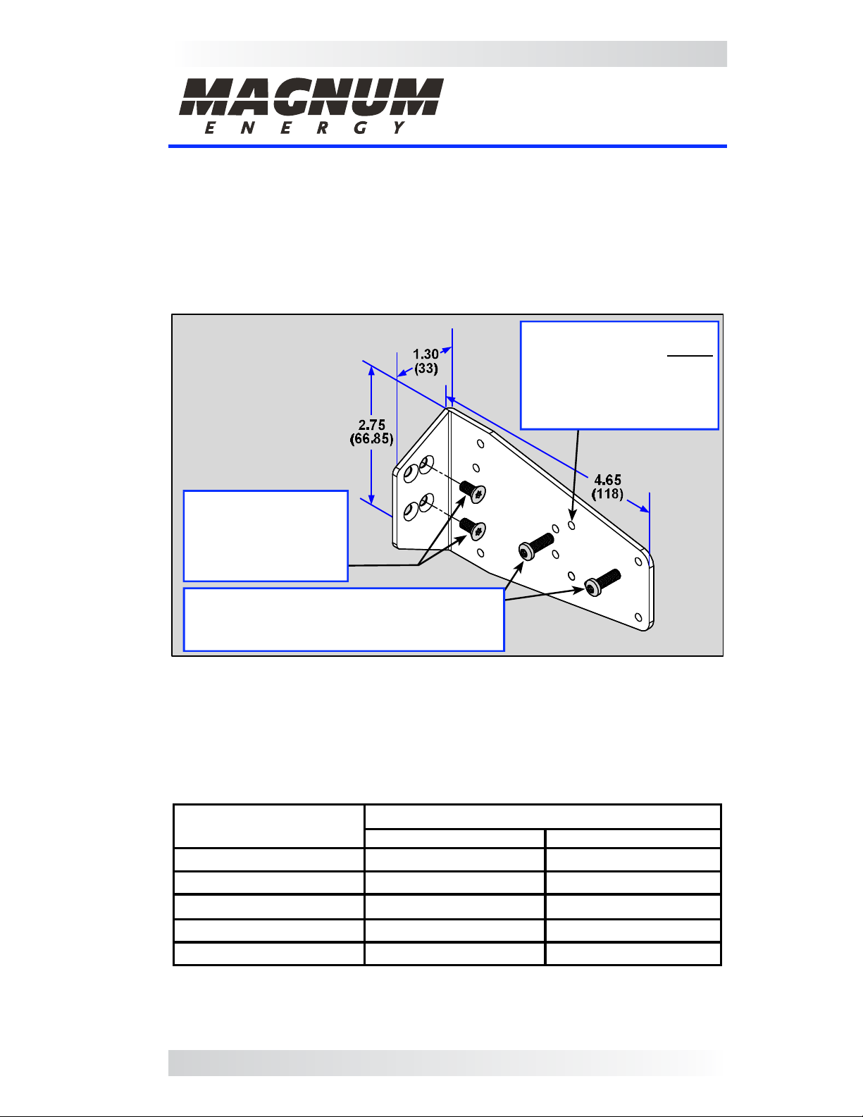
enclosure and to attach a controller to the bracket (see Figure 1).
Holes (x10) for mounting
Sizes shown in
inches (mm)
a charge controller. Before
attaching the bracket, use
the form threading screws
provided to pre-thread the
hole(s) you will use.
Two #8-32 x 3/8” fl at
head Torx drive (T15)
screws to attach the
bracket to the
MMP/MP enclosure.
Two thread forming #8-32 x 1/2” Torx drive
(T20) screws to mount a charge controller.
Most controllers only use one screw.
Figure 1, MP-CCB Physical Dimensions
Installation
Before proceeding, use Table 1 to determine for your particular charge controller:
• which side of the enclosure (left or right) to mount the charge controller,
• which enclosure mounting holes (upper or lower) to use to attach the bracket,
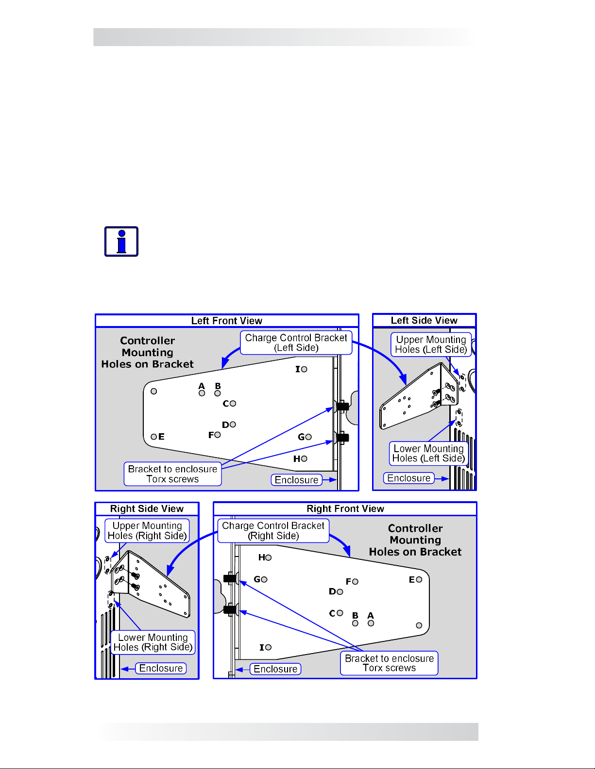
• which bracket hole(s) (A-I) to use to mount the charge controller (see Figure 2).
Table 1, Mounting Holes Used for Charge Controllers
Charge
Controller
PT-100 (ME) (I) / [upper] (H) / [upper]
Classic w/o Turbo (MN) (B) / [upper] (F) / [upper]
Classic w/Turbo (MN) (A) / [upper] (F) / [upper]
FlexMax 80 (OB)
1
Tristar (MS) (D) / [lower] (C) / [lower]
(ME) = Magnum Energy, (MN) = MidNite, (OB) = OutBack, (MS) = MorningStar
Note 1 - The FlexMax 80 is taller than most controllers and may not fi t if something
is mounted above it. If an MPX extension is to be installed on an MP enclosure, mount
the MPX on the left side to allow the FlexMax 80 to be mounted on the right-hand side.
Holes to use: (Bracket) / [Enclosure]
Left Side Install Right Side Install
NA (G) and (E) / [upper]
Part Number: 64-0044 Rev D 1
Page 2
MP-CCB Instruction Sheet
Refer to Figure 2 to locate the holes you will use to attach the bracket to
the enclosure and to mount the controller to the bracket. Use the provided
thread forming screws (T20 Torx drive) to pre-thread the selected mounting
holes. It is easier to do this now rather than after it is installed.
After pre-threading the particular bracket hole(s), attach the bracket to the
enclosure. Before you mount the charge controller to the attached bracket,
remove the appropriate knockout from the side of the controller and an
adjacent knockout on the side of the enclosure. This allows you to use a 1”
close nipple with two locknuts to secure the charge controller to the enclosure
(in addition to the bracket), and provides a path to run the necessary wiring
between the two units. Mount the controller to the attached bracket using
the supplied hardware. Insert the close nipple through the knockouts and
secure with the locknuts.
Info: It may take three locknuts on the close nipple to anchor the
controller to the enclosure. An additional locknut may be required
between the enclosure and the controller to act as a spacer. Also,
a standard 1” plastic bushing should be used on the nipple ends to
protect the wire insulation as it enters/exits the nipple.
Figure 2, Mounting Holes
2 © 2014 Magnum Energy, Inc.
 Loading...