

Page 1
MM-AE Series
Inverter/Chargers
Owner’s Manual
Page 2
Disclaimer of Liability
The use of this manual and the conditions or methods of installation,
operation, use, and maintenance of the MM-AE Series Inverter/
Charger are beyond the control of Magnum Energy, Inc. Therefore,
this company assumes no responsibility and expressly disclaims
any liability for loss, damage, or expense whether direct, indirect,
consequential, or incidental that may arise out of or be in any way
connected with such installation, operation, use, or maintenance.
Due to continuous improvements and product updates, the images
shown in this manual may not exactly match the unit purchased.
Restrictions on Use
The MM-AE Series Inverter/Charger may only be used in life-support
devices or systems with the express written approval of Magnum
Energy. Failure of the MM-AE Series Inverter/Charger can reasonably
be expected to cause the failure of that life-support device or system,
or to affect the safety or effectiveness of that device or system. If the
MM-AE Series Inverter/Charger fails, it is reasonable to assume that
the health of the user or other persons may be endangered.
Contact Information
Magnum Energy, Inc.
2211 West Casino Rd.
Everett, WA 98204
Phone: (425) 353-8833 / Fax: (425) 353-8390
Web: www.magnumenergy.com
Record the unit’s model and serial number in case you need to provide
this information in the future. It is much easier to record this information
now, instead of trying to gather it after the unit has been installed.
Model: Serial Number:
MM612AE Q1
MM1512AE AG
MM1524AE S1
Conventions Used in this Manual
Terminology
AC source or External AC power - refers to Alternating Current
(AC) provided by the utility electric power grid or from a generator.
AE application - typically refers to using the inverter in a system that
uses Alternative Energy (e.g., solar, wind, or hydro). This term is also
used to refer to inverters used in a home, offi ce, or cabin installation.
i
© 2010 Magnum Energy, Inc.
Page 3
Safety symbols
To reduce the risk of electrical shock, fi re, or other safety hazard, the
following safety symbols have been placed throughout this manual
to indicate dangerous and important safety instructions.
WARNING: This symbol indicates that failure to take a
specifi ed action could result in physical harm to the user.
CAUTION: This symbol indicates that failure to take a
specifi ed action could result in damage to the equipment.
Info: This symbol indicates information that emphasizes
or supplements important points of the main text.
IMPORTANT PRODUCT SAFETY INSTRUCTIONS
This manual contains important safety instructions that must be followed during the installation and operation of this product. Read all
instructions and safety information contained in this manual before
installing or using this product.
• All electrical work must be performed in accordance with local,
state, and federal electrical codes.
• This product is designed for indoor/compartment installation.
DO NOT expose to rain, snow, moisture, or liquids of any type.
• Use insulated tools to reduce the chance of electrical shock or
accidental short circuits.
• Remove all jewelry such as rings, watches, bracelets, etc., when
installing or performing maintenance on the inverter.
• Always disconnect the batteries or energy source prior to
installing or performing maintenance on the inverter. Live power
may be present at more than one point since an inverter utilizes
both batteries and AC. Turning off the inverter may not reduce
this risk. As long as AC power is connected, it will pass through
the inverter regardless of the ON/OFF power switch setting.
• Always verify proper wiring prior to starting the inverter.
• Do not operate the inverter if it has been damaged.
• Do not dismantle the inverter; there are no user-serviceable
parts contained in this product. Attempting to service the unit
yourself could cause electrical shock. Internal capacitors remain
charged after all power is disconnected.
• No AC or DC disconnects are provided as an integral part of this
inverter. Both AC and DC disconnects must be provided as part
of the system installation.
© 2010 Magnum Energy, Inc.
ii
Page 4

• No overcurrent protection for the battery supply is provided as
an integral part of this inverter. Overcurrent protection of the
battery cables must be provided as part of the installation.
• No overcurrent protection for the AC output wiring is provided as
an integral part of this inverter. Overcurrent protection of the AC
output wiring must be provided as part of the installation.
IMPORTANT BATTERY SAFETY INSTRUCTIONS
• Wear eye protection (safety glasses) when working with
batteries.
• Remove all jewelry such as rings, watches, bracelets, etc., when
installing or performing maintenance on the inverter.
• Never work alone. Always have someone near you when working
around batteries.
• Use proper lifting techniques when working with batteries.
• Never use old or untested batteries. Check each battery’s label
for age, type, and date code to ensure all batteries are identical.
• Batteries are sensitive to changes in temperature. Always install
batteries in a stable environment.
• Install batteries in a well ventilated area. Batteries can produce
explosive gasses. For compartment or enclosure installations,
always vent batteries to the outside.
• Provide at least one inch of air space between batteries to
provide optimum cooling.
• Never smoke when in the vicinity of batteries.
• To prevent a spark at the battery and reduce the chance of
explosion, always connect the cables to the batteries fi rst. Then
connect the cables to the inverter.
• Use insulated tools at all times.
• Always verify proper polarity and voltage before connecting the
batteries to the inverter.
• To reduce the chance of fi re or explosion, do not short-circuit the
batteries.
• In the event of accidental exposure to battery acid, wash
thoroughly with soap and water. In the event of exposure to the
eyes, fl ood them for at least 15 minutes with running water and
seek immediate medical attention.
• Recycle old batteries.
iii
SAVE ALL INSTRUCTIONS
© 2010 Magnum Energy, Inc.
Page 5

Table of Contents
1.0 Introduction ..................................................................1
MM-AE Series Models ............................................................ 1
How an Inverter/Charger Works ............................................. 2
Appliances that will run from a Modifi ed Sine Inverter ............... 2
Appliances and Run Time ....................................................... 2
Standard Features and Benefi ts .............................................. 3
Battery Temperature Sensor .............................................. 5
2.0 Installation ....................................................................6
Pre-Installation .................................................................... 6
Unpacking and Inspection ...................................................... 6
Locating and Mounting the Inverter ......................................... 8
Wiring Guidelines ................................................................10
DC Wiring ...........................................................................11
DC Wire Sizing and Overcurrent Protection .........................11
DC Overcurrent Protection ................................................13
DC Grounding .................................................................13
DC Cable Connections ......................................................14
Battery Bank Wiring ............................................................15
Inverter to Battery Bank Wiring ............................................15
DC Ground Wire ..............................................................16
DC Negative Wire ............................................................16
Battery Temperature Sensor .............................................16
DC Positive Wire .............................................................16
AC Wiring ...........................................................................17
Neutral to Safety Ground Bonding .....................................17
AC Wiring Connections .....................................................18
AC Wire Size and Overcurrent Protection ............................18
AC Input Wiring ..............................................................19
AC Output Wiring ............................................................20
Ground-Fault Circuit Interruption Breakers .........................21
Functional Test ....................................................................21
3.0 Operation ................................................................... 23
Operating Modes .................................................................23
Inverter Mode .................................................................23
Standby Mode ................................................................24
Protection Circuitry Operation ...............................................28
Inverter Start-up .................................................................29
ON/OFF Switch ...............................................................29
Status LED Indicator .......................................................29
Factory Default Settings .......................................................30
4.0 Maintenance and Troubleshooting ...............................32
Recommended Inverter and Battery Care ...............................32
Resetting the Inverter ..........................................................32
© 2010 Magnum Energy, Inc.
iv
Page 6

Table of Contents
5.0 Specifi cations .............................................................. 34
Appendix A - Optional Equipment and Accessories ............35
Appendix B - Battery Information .....................................36
Battery Bank Sizing .............................................................36
Battery Types .....................................................................36
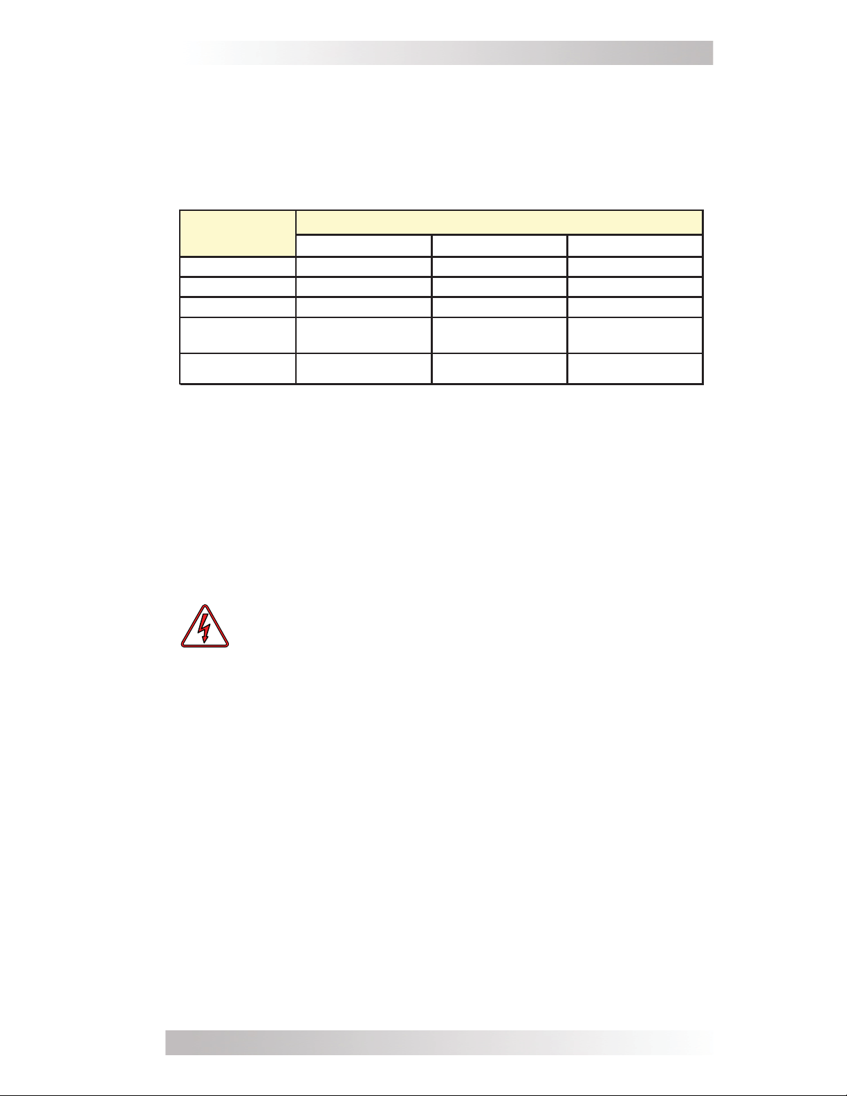
Battery Confi guration ...........................................................36
Series Wiring ..................................................................36
Parallel Wiring ................................................................37
Series-Parallel Wiring .......................................................37
Appendix C - Warranty/Service Information .....................40
How to Receive Repair Service ..............................................41
List of Figures
Figure 1, MM-AE Series Inverter/Charger .................................. 1
Figure 2, Top Side Features ..................................................... 3
Figure 3, Front and Back Side Features ..................................... 4
Figure 4, Left Side Features .................................................... 5
Figure 5, Battery Temperature Sensor (BTS) ............................. 5
Figure 6, Basic Installation Diagram ......................................... 7
Figure 7, Approved Mounting Orientations ................................. 9
Figure 8, MM-AE Series Inverter/Charger Dimensions ................10
Figure 9, DC Cable to Battery Terminals ...................................14
Figure 10, DC Cable to Inverter’s DC Terminals .........................14
Figure 11, AC Wiring Connections ...........................................20
Figure 12, Automatic 4-Stage Charging Graph ..........................26
Figure 13, BTS Temperature to Charge Voltage Change ..............27
Figure 14, Series Battery Wiring .............................................36
Figure 15, Parallel Battery Wiring ............................................37
Figure 16, Series-Parallel Battery Wiring ..................................37
Figure 17, Battery Bank Wiring Examples (12-volt) ...................38
Figure 18, Battery Bank Wiring Examples (24-volt) ...................39
List of Tables
Table 1, Recommended DC Wire/Overcurrent Device .................12
Table 2, DC Wire Size For Increased Distance ...........................13
Table 3, Wire Color to AC Wire Connection ...............................18
Table 4, Minimum Wire Size to Circuit-breaker Size ...................19
Table 5, Inverter Battery Turn On/Off Levels .............................29
Table 6, Inverter/Charger Default Settings ...............................31
Table 7, Troubleshooting Guide ...............................................33
Table 8, MM-AE Series Specifi cations .......................................34
© 2010 Magnum Energy, Inc.v
Page 7
1.0 Introduction
1.0 Introduction
Congratulations on your purchase of an MM-AE Series inverter/charger from Magnum Energy, Inc. This product is designed especially for
your back-up power or standalone application. Powerful, yet simple
to use, the Magnum Energy inverter will provide you with years of
trouble-free use.
Please read this chapter to familiarize yourself with the features and
benefi ts of your particular MM-AE Series model.
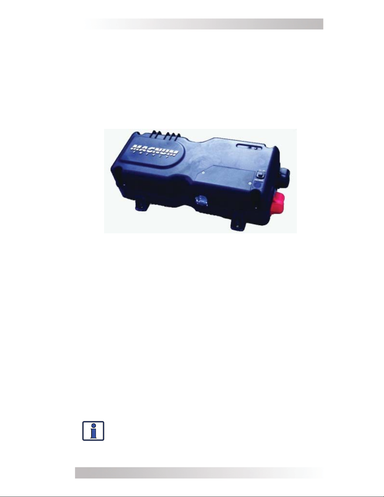
Figure 1, MM-AE Series Inverter/Charger
MM-AE Series Models
MM612AE - a 600 watt inverter/charger with 7 amp AC transfer
capability and 30 amp/12 VDC, 4-stage PFC charger. The AC input
and output are provided with pigtail wires to allow hardwiring to a
main AC distribution panel and to an inverter sub-panel. Includes a
15’ battery temperature sensor.
MM1512AE - a 1500 watt inverter/charger with 12 amp AC transfer
capability and 70 amp/12 VDC, 4-stage PFC charger. The AC input
and output are provided with pigtail wires to allow hardwiring to a
main AC distribution panel and to an inverter sub-panel. Includes a
15’ battery temperature sensor.
MM1524AE - a 1500 watt inverter/charger with 12 amp AC transfer
capability and 35 amp/24 VDC, 4-stage PFC charger. The AC input
and output are provided with pigtail wires to allow hardwiring to a
main AC distribution panel and to an inverter sub-panel. Includes a
15’ battery temperature sensor.
Info: These units have common input/output neutrals
for uses in AE applications (i.e., homes/cabins/offi ces).
If your installation is for a mobile application (RV, truck,
or boat), the appropriate model for these applications is
the MM or MMS Series inverter.
© 2010 Magnum Energy, Inc.
1
Page 8

1.0 Introduction
How an Inverter/Charger Works
An inverter takes direct current (DC) from your batteries and turns
it into alternating current (AC), like you use at home. With MM-AE
Series models, it also takes alternating current (when connected to
a generator or to utility power) and transforms it into direct current
to recharge your batteries.
The two modes of operation associated with this inverter/charger are
referred to in this document as:
Inverter Mode: DC from the batteries is transformed into modifi ed
sine wave AC for powering your AE applications.
Standby Mode: The unit operates as a battery charger to convert
incoming AC power into DC power to recharge the batteries while continuing to pass the incoming AC power directly to the inverter’s output
to power any AC loads.
Appliances that will run from a Modifi ed Sine Inverter
Today’s inverters come in two basic output waveforms: modifi ed sine
(actually a modifi ed square wave) and pure sine wave. Modifi ed sine
wave inverters approximate a pure sine waveform.
The output of a modifi ed sine wave inverter will run most electronic
and household items including but not limited to TV, VCR, satellite dish
receiver, computers, and printers. Some devices such as rechargeable
power supplies for phones, drills, and other like devices may not run
or be damaged by modifi ed sine wave inverters.
Appliances and Run Time
The MM-AE Series inverter/charger can power a wide range of household appliances. As with any appliance using batteries for power, there
is a certain length of time that it can run – this is called “run time”.
Actual run time depends on several variables including the size and
the type of appliance, the type of batteries installed in your application, as well as the battery’s capacity and age. Other factors such
as the battery’s state of charge and temperature can also affect the
length of time your appliances can run.
Depending on your inverter capacity, larger electrical appliances such
as coffee pots and hair dryers can be used for short durations. However, loads that are used for longer periods such as stoves or water
heaters can quickly drain your batteries and are not recommended
for inverter applications.
All electrical appliances are rated by the amount of power they consume. The rating is printed on the product’s nameplate label, usually located on its chassis near the AC power cord. Even though it is
diffi cult to calculate exactly how long an inverter will run a particular
appliance, the best advice is trial and error. Your MM-AE Series inverter/charger has a built-in safeguard that automatically protects
your batteries from being over-discharged.
© 2010 Magnum Energy, Inc.2
Page 9
1.0 Introduction
Standard Features and Benefi ts
The MM-AE Series inverter/charger converts 12 or 24 volts (de-
pending on model) direct current (VDC) power from your battery to
120 volts alternating current (VAC) power.
charger optimizes incoming AC power using Power Factor Correction
(PFC) technology to keep the inverter’s battery bank fully charged.
This inverter is designed to allow easy installation and use, and with
its die-cast aluminum baseplate it ensures maximum durability and
cooler more effi cient operation.
The inverter/charger provides the following:
• 600 or 1500 watts continuous (depending on model) at 25°C.
• Numerous protection features to provide a safe and
peace-of-mind operation.
• AC transfer switch circuitry; allowing incoming AC power to
continue to pass-thru to power loads even if the inverter is off.
• Dead battery charging for batteries that are extremely low.
The multi-stage battery
• Automatic 4-stage battery charger with power factor correction
and temperature compensation – for optimum battery charging
(using the temperature sensor).
• Modern and aesthetically pleasing design with large AC wiring
compartment (provides easy access to AC wiring for simple and
quick connections) and 360° DC connection terminals with color
coded insulating covers.
• True RMS output voltage regulation to ensure the inverter will
deliver the correct amount of power – within the DC input volt age range and the continuous output power level.
• Quick connection accessory and remote ports – easily accepts
several optional remote controls and the Battery Temperature
Sensor.
21
3
5
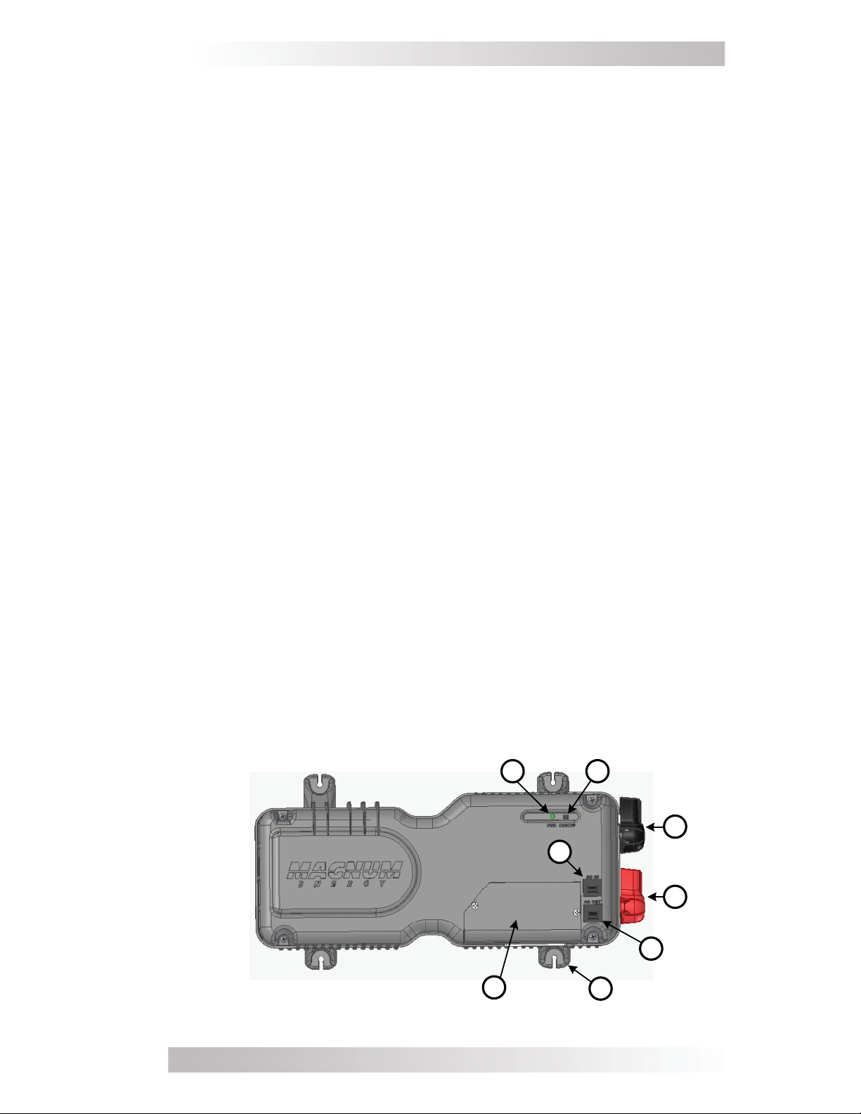
Figure 2, Top Side Features
© 2010 Magnum Energy, Inc.
4
6
8
7
3
Page 10
1.0 Introduction
1. Inverter Status Indicator - this green LED illuminates to
provide information on the inverter’s operation.
2. Power Switch - momentary pushbutton switch that turns the
inverter on or off.
3. Negative DC Terminal (black) - the inverter’s connection to
the negative terminal on the battery bank.
4. Positive DC Terminal (red) - the inverter’s connection to the
positive terminal on the battery bank.
5. Input Circuit Breaker - this circuit breaker protects the unit’s
internal wiring and pass-thru relay.
6. Output Circuit Breaker - this circuit breaker provides another
layer of overload protection. This is not a branch-circuit rated
breaker. Separate AC output breakers are required on the output.
7. Mounting Flanges (x4) - secures the inverter to shelf/wall.
8. AC Wiring Compartment - provides access for all AC input
and output connections on the inverter.
Front S ide
9
10
11
12
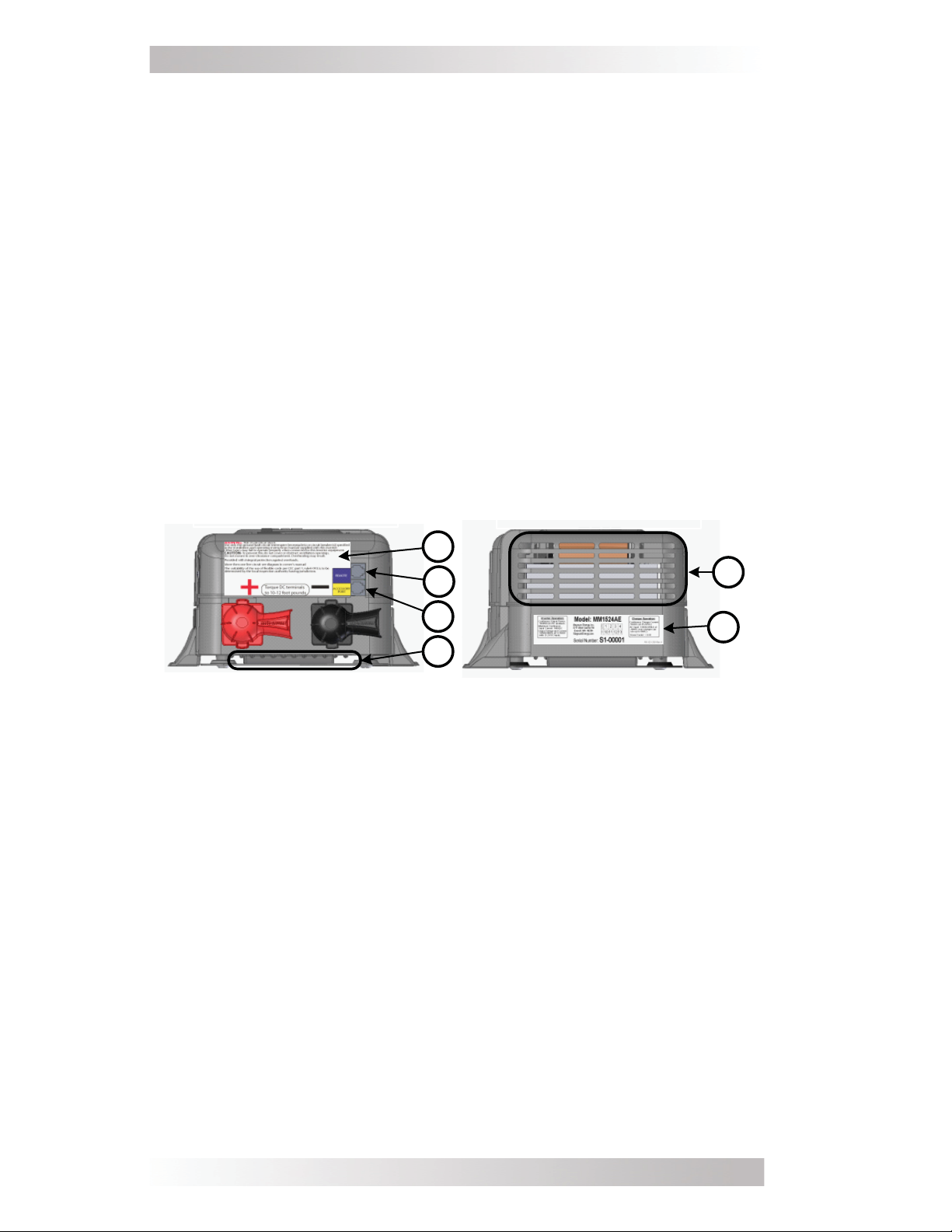
Figure 3, Front and Back Side Features
9. Warning and Information Label - provides pertinent
information for safely using the inverter.
10. REMOTE Port Connection - a RJ11 connector that allows an
optional remote control to be connected.
11. ACCESSORY PORT Connection - a RJ11 connector to allow
the Battery Temperature Sensor (BTS) or MM-AE accessories (e.g.,
MM-DCLD) to be connected.
12. Intake Vent - ventilation openings to pull in air to help keep
the inverter cool for peak performance.
Back Side
13
14
13. Exhaust Vent - ventilation openings that allow heated air to
be removed by the internal cooling fan.
14. Model/Serial Number Label - includes model/serial number
and provides specifi cations and information on the inverter and
charger. See the MM-AE Series Specifi cations on page 34 for
more information and the different models available.
4
© 2010 Magnum Energy, Inc.
Page 11
1.0 Introduction
15
16
17
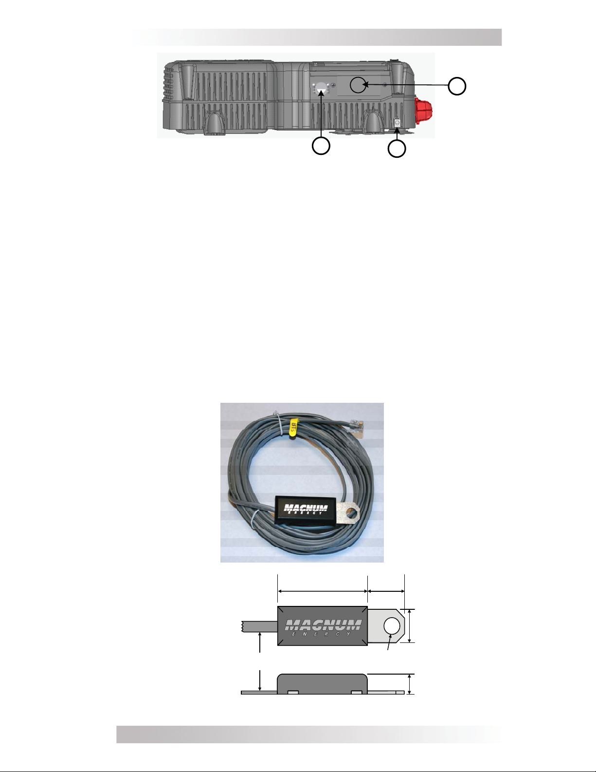
Figure 4, Left Side Features
15. AC Output Connection - AC knockout (output) for
hardwiring.
16. AC Input Connection
- AC knockout (input) for hardwiring.
17. DC Ground Terminal - this connection is used to tie the
exposed chassis of the inverter to the DC grounding system. This
terminal accepts CU/AL conductors from #14 AWG to #6 AWG.
Battery Temperature Sensor
A plug-in external Battery Temperature Sensor (BTS) is provided
for units with the battery charger feature. When installed, the
BTS automatically adjusts the battery charger’s BULK, ABSORB,
and FLOAT voltage set-points (based on temperature) for better
charging performance and longer battery life. If the temperature
sensor is NOT installed and the batteries are subjected to large
temperature changes, battery life may be shortened.
FRONT VIEW
Cable
SIDE VIEW
Figure 5, Battery Temperature Sensor (BTS)
© 2010 Magnum Energy, Inc.
~2"
~1"
~¾”
0.375" diameter
~½”
5
Page 12

2.0 Installation
2.0 Installation
Pre-Installation
Before installing the inverter, read the entire Installation section. The
more thorough you plan in the beginning, the better your inverter
needs will be met.
WARNING: Installations should be performed by qualifi ed
personnel, such as a licensed or certifi ed electrician. It
is the installer’s responsibility to determine which safety
codes apply, and to ensure that all applicable installation
requirements are followed. Applicable installation codes
vary depending on the specifi c location and the type of
installation.
Info: Review the “Important Product Safety Information”
on page ii and the “Important Battery Safety Instructions”
on page iii before any installation.
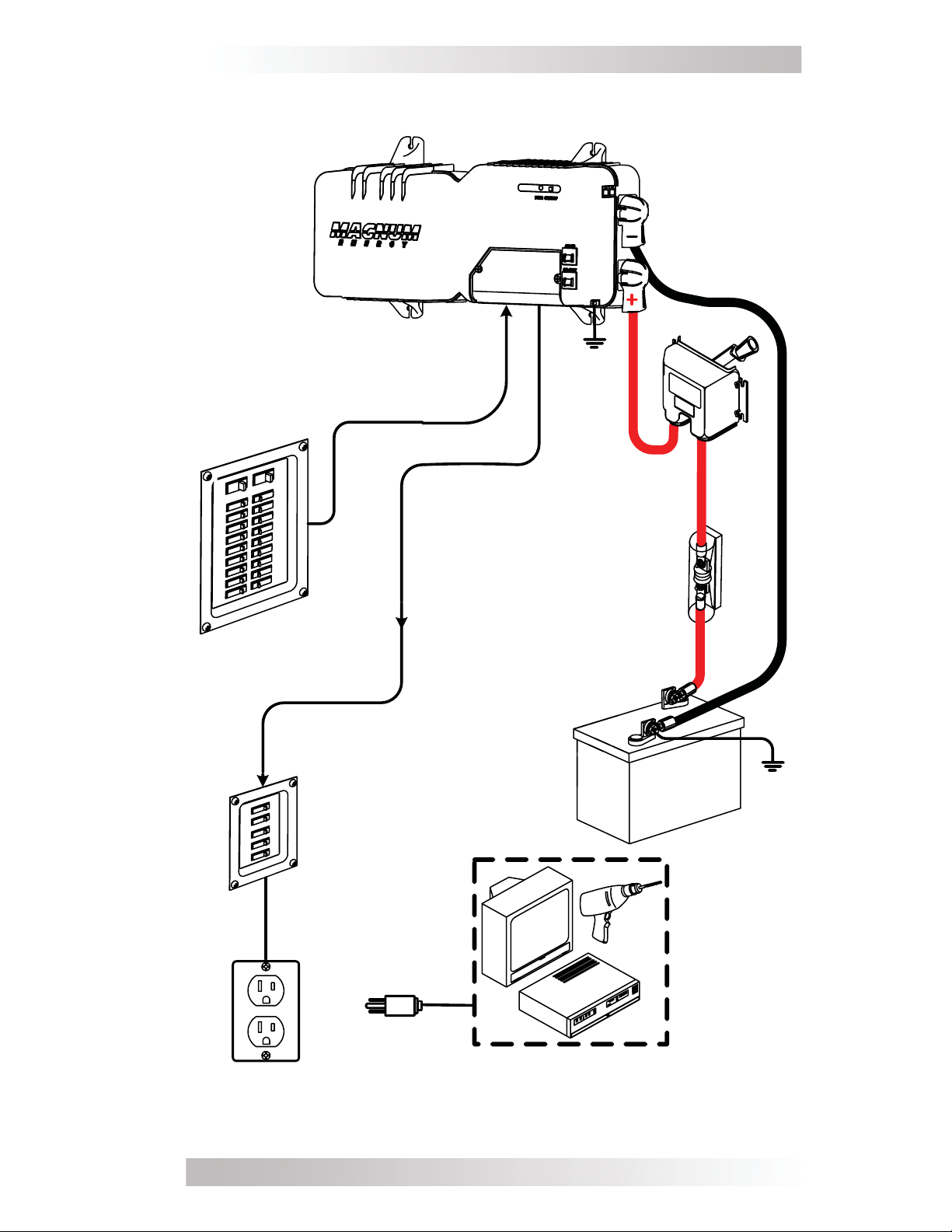
The basic system diagram shown in Figure 6
assist you in planning and designing your installation.
should be reviewed to
Unpacking and Inspection
Carefully remove the MM-AE Series inverter/charger from its shipping container and inspect all contents. Verify the following items
are included:
− MM-AE Series inverter/charger
− Red and black DC terminal covers
− AC access cover with two screws
− Two 1/2” hex-head kep nuts (installed on the DC terminals)
− Battery Temperature Sensor (BTS)
− MM-AE Series Owner’s Manual
If items appear to be missing or damaged, contact your authorized
Magnum Energy dealer or Magnum Energy.
If at all possible, keep your shipping box. It will help protect your
inverter from damage if it ever needs to be returned for service.
Save your proof-of-purchase as a record of your ownership; it will
also be needed if the unit should require in-warranty service.
Record the unit’s model and serial number in the front of this manual
in case you need to provide this information in the future. It is much
easier to record this information now, instead of trying to gather it
after the unit has been installed.
6
© 2010 Magnum Energy, Inc.
Page 13
MM -AE Series Inverter
AC IN
DC
Ground
AC
OUT
disconnect
overcurrent
2.0 Installation
DC
and
device
AC
Main Panel
Outlet
AC
Sub-Panel
AC
TV
VCR
B attery
B ank
Tools
A C Loads
Figure 6, Basic Installation Diagram
© 2010 Magnum Energy, Inc.
7
Page 14

2.0 Installation
Locating and Mounting the Inverter
WARNINGS:
• Do not mount the inverter near any fl ammable or
combustible fl uid or components.
• Provide adequate clearance/ventilation to the inverter.
• Mount only on a non-combustible surface.
• Maximum ambient temperature around the inverter must
not exceed 77° F (25° C) to meet power specifi cations.
The inverter should only be installed in a location that meets the
following requirements:
Clean and Dry - The inverter should not be installed in an area that
allows
ventilation openings. The area also must be free from any risk of
condensation, water,
inverter. The inverter uses stainless steel fasteners, plated copper
busbars, and a power-coated aluminum base. Also, the internal circuit
boards are conformal coated. The above measures are undertaken
to help fi ght the harmful effects of corrosive environments. However,
the life of the inverter is uncertain if used in any of these types of
environments, and inverter failure under these conditions is not covered
under warranty.
dust, fumes, insects, or rodents to enter or block the inverter’s
or any other liquid that can enter or fall on the
Cool - The inverter should be
sun or any equipment that produces extreme heat.
protected from direct exposure to the
The ambient air
temperature should be between 32° F (0° C) and 104° F (40° C);
keep in mind that the inverter’s output specifi cations are rated at 77°
F (25° C), so the cooler the better within this range.
Ventilated - In order for the inverter to provide full output power
and avoid over-temperature fault conditions do not cover or block
the inverter’s ventilation openings, or install this inverter in an area
with limited airfl ow. Allow as much clearance around the inverter’s
intake and exhaust ventilation openings as possible, see Items 12
and 13 in Figure 3. At the minimum, allow an airspace clearance of
6” (15 cm) at the front and back, and 3” (7.5 cm) everywhere else
to provide adequate ventilation.
If installed in an enclosure, a fresh air intake opening must be provided directly to the front side (intake vent) and an exhaust opening on the back side (exhaust vent) of the inverter. This will allow
cool air from the outside to fl ow into the inverter, and heated air to
exit away from the inverter and the enclosure. When mounted in an
enclosed compartment, airfl ow must be at least 59 cfm in order to
maintain no more than a 68° F (20° C) rise in compartment temperature. Minimum clearances can be reduced if airfl ow is increased,
but in no case should clearance around the inverter be less than 2”
(5 cm) on all sides.
8
© 2010 Magnum Energy, Inc.
Page 15
2.0 Installation
Safe - Keep any fl ammable/combustible material (e.g., paper, cloth,
plastic, etc.) that may be ignited by heat, sparks, or fl ames at a
minimum distance of 2 feet (60 cm) away from the inverter. Do not
install this inverter in any area that contains extremely fl ammable
liquids like gasoline or propane, or in locations that require ignitionprotected devices.
Close to the battery bank - As with any inverter, it should be
located as close to the batteries as possible. Long DC wires tend to
lose effi ciency and reduce the overall performance of an inverter.
However, the unit should not be installed in the same compartment as
the batteries or mounted where it will be exposed to gases produced
by the batteries. These gases are corrosive and will damage the
inverter. Also, if these gases are not ventilated and allowed to collect,
they could ignite and cause an explosion.
Accessible -
Do not block access to the inverter’s remote control and
accessory ports. Also, allow enough room to access the AC and DC wiring
connections, as they will need to be checked and tightened periodically.
See Figure 8 for the MM-AE Series’ inverter dimensions.
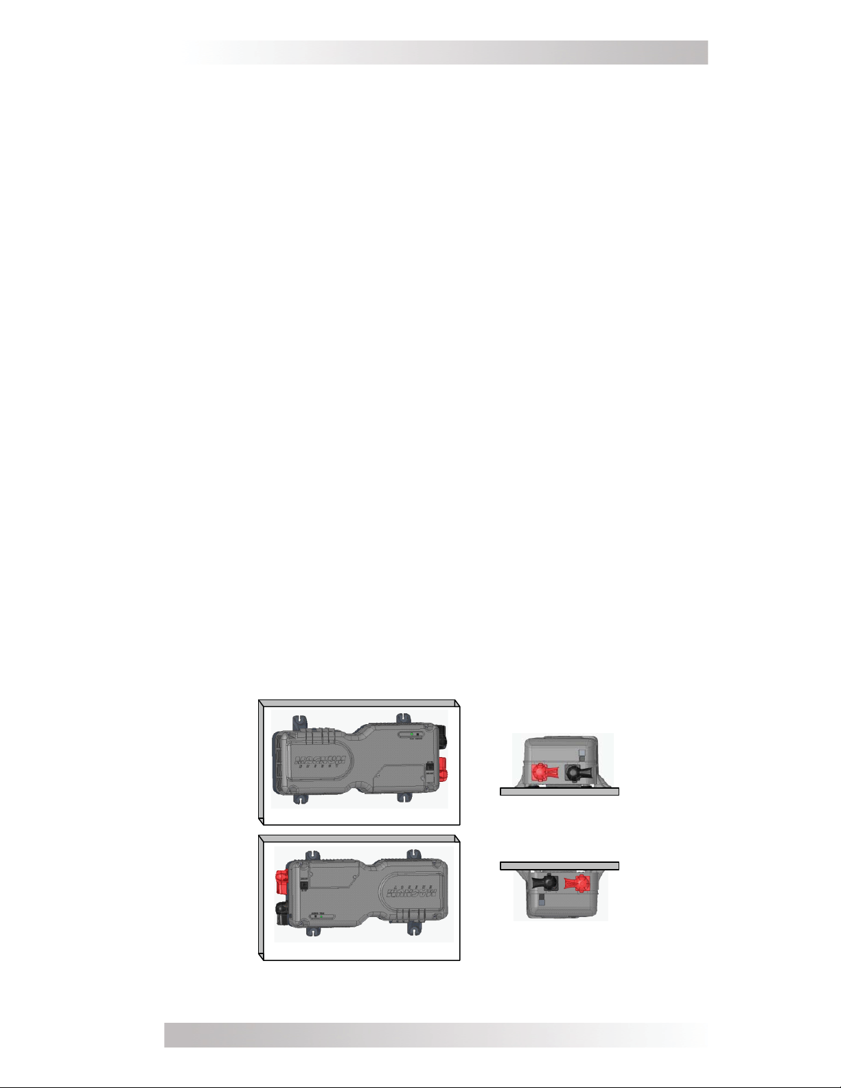
Mounting Orientation - To meet regulatory requirements, the
MM-AE Series inverter/charger can only be mounted
on a horizontal
surface (shelf or table) or a vertical surface (wall or bulkhead) either
right-side up or upside-down, as shown in Figure 7. The inverter must
be mounted on a non-combustible surface, and this surface and the
mounting hardware must be capable of supporting at least twice the
weight of the inverter. After determining your mounting position, use
the base of the inverter’s chassis as a template to mark your mounting
screw locations. Remove the inverter and drill pilot holes into the
mounting surface.
After the inverter has been properly mounted, proceed to the DC
Wiring section.
Shelf Mounted
(right-side up)
Wall Mounted (right-side up)
Wall Mounted (up-side down)
Figure 7, Approved Mounting Orientations
© 2010 Magnum Energy, Inc.
Shelf Mounted
(up-side down)
9
Page 16

2.0 Installation
5/8"
~ 16
(16.5 9")
M ounting holes x 4
[¼ ” (0.25 ") diameter]
10 .0"
11 /16"
~ 4
(4.66")
~ 6 3/4" (6.71")
~ 7 ½" (7.51")
~ 8 7/16" (8.41")
Figure 8, MM-AE Series Inverter/Charger Dimensions
Wiring Guidelines
• Before connecting any wires, determine all wire routes to and
from the inverter throughout the home or cabin.
• Conductors passing through walls or other structural members
must be protected to minimize insulation damage such as
chafi ng, which can be caused by vibration or constant rubbing.
• Always check for existing electrical, plumbing, or other areas
of potential damage prior to making cuts in structural surfaces or
walls.
• Make sure all wires have a smooth bend radius and do not be come kinked.
• Both AC and DC overcurrent protection must be provided as part
of the installation.
© 2010 Magnum Energy, Inc.10
Page 17

2.0 Installation
• DC wires and cables should be tied together with wire ties or
electrical tape approximately every 6 inches. This helps improve
the surge capability and reduces the effects of inductance, which
improves the inverter waveform and reduces wear on the
inverter’s fi lter capacitors.
• Use only copper wires with a minimum temperature rating of
75°C.
• To ensure the maximum performance from the inverter, all
connections from the battery bank to the inverter should be
minimized; the exceptions are the DC overcurrent disconnect in
the positive line and a shunt in the negative line. Any other ad ditional connection will contribute to additional voltage drops,
and these extra connections points may loosen during use.
• All wiring to the battery terminals should be checked periodically
(once a month) for proper tightness. The torque requirement
for the DC terminals is between 10 to 12 foot-pounds. If you
don’t have a torque wrench, ensure all DC terminals are tight
and cannot move.
CAUTION: Be aware that overtightening and misthreading
the nuts on the DC terminals can cause the bolts to strip
and snap/break off.
DC Wiring
This section describes the inverter’s required DC wire sizes and the
recommended disconnect/overcurrent protection, and how to make
the DC connections to the inverter and the battery bank.
DC Wire Sizing and Overcurrent Protection
It is important to use the correct DC wire to achieve maximum effi ciency from the system and reduce fi re hazards associated with
overheating. See Table 1 to select the minimum DC wire size needed
based on your inverter model. If the distance from the inverter to the
battery bank is greater than 3 feet, use Table 2 to help determine
the minimum recommended cable sizes for longer distances. Always
keep your wire runs as short as practical to help prevent low voltage shutdowns, and keep the DC breaker from nuisance tripping (or
open fuses) because of increased current draw. Undersized cables
can also lower the inverter’s peak output voltage, as well as reduce
its ability to surge heavy loads.
Info: The DC wires must be color coded with colored
tape or heat shrink tubing; RED for positive (+), BLACK
for negative (-), and GREEN for DC ground.
© 2010 Magnum Energy, Inc.
11
Page 18
2.0 Installation
The DC wires must have soldered and crimped lugs, crimped copper
compression lugs, or aluminum mechanical lugs. Soldered connections alone are not acceptable for this application.
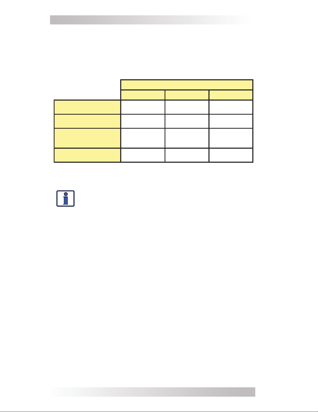
Table 1, Recommended DC Wire/Overcurrent Device
Inverter Model
MM612AE MM1512AE MM1524AE
Maximum Continuous
Current¹
DC Grounding
Electrode Wire Size
Minimum DC Wire Size
(90˚C rating in free air)
Maximum DC
Fuse Size
80 amps 200 amps 100 amps
# 6 AWG # 6 AWG # 6 AWG
# 2 AWG
(190 amps)
200 amps with
time delay
# 1/0 AWG
(260 amps)
300 amps with
time delay
# 1/0 AWG
(260 amps)
300 amps with
time delay
Info: The term “in free air” is defi ned by the NEC as not
encased in conduit or raceway.
If the inverter is expected to operate at a distance greater than
three feet from the battery bank, the DC wire size will need to be
increased to overcome the increase in resistance – which affects the
performance of the inverter. Continue to use the overcurrent device
and DC ground wire previously determined from Table 1 and then,
refer to Table 2 to determine the minimum DC wire size you need for
various distances based on your inverter model.
Note 1 - Maximum Continuous Current is based on the inverter’s continuous
power rating at the lowest input voltage with an ineffi ciency factor.
Note 2 - Per the NEC, the DC grounding electrode conductor can be a #6
AWG conductor if that is the only connection to the grounding electrode and
that grounding electrode is a pipe, rod, or plate electrode.
Note 3 - Wire size is based on the requirements needed to increase effi cien-
cy and reduce stress to the inverter.
Note 4 - The next larger standard size overcurrent device may be used if
the de-rated cable ampacity falls between the standard overcurrent devices
found in the NEC.
12
© 2010 Magnum Energy, Inc.
Page 19

2.0 Installation
Table 2, DC Wire Size For Increased Distance
Minimum recommended DC wire size (one way)
3 ft or less 3 to 5 ft 5 to 10 ft 10 to 15 ft
MM612AE #2 AWG #1 AWG #1/0 AWG #2/0 AWG
MM1512AE # 1/0 AWG #1/0 AWG #2/0 AWG #4/0 AWG
MM1524AE # 1/0 AWG #1/0 AWG #2/0 AWG #4/0 AWG
DC Overcurrent Protection
For safety and to comply with NEC (National Electrical Code) electrical
code regulations, you must install a DC overcurrent protection device
in the positive DC cable line to protect your DC cables. This DC
overcurrent device can be a fuse or circuit-breaker, but must be DC
rated. It must be correctly sized according to the size of DC cables
being used, which means it is required to open before the cable
reaches its maximum current carrying capability, thereby preventing
a fi re.
minimum wire size for your inverter model.
See Table 1 to select the DC overcurrent device based on the
If using a fuse, we recommend using a
This fuse type is rated for DC operation, can
circuit currents, and
allows for momentary current surges from the
class-T type or equivalent.
handle the high short-
inverter without opening.
DC Grounding
The inverter/charger should always be connected to a permanent,
grounded wiring system.
The idea is to connect the metallic chassis
of the various enclosures together to have them at the same voltage
potential, which reduces the possibility for electric shock.
For the
majority of installations, the inverter chassis and the negative battery
conductor are connected to the system’s ground bond via a safetygrounding conductor (bare wire or green insulated wire) at only one
point in the system. Per the NEC, the size for the grounding conductor
is usually based on the size of the overcurrent device used in the DC
system.
Refer to Table 1 to select the appropriate DC ground wire
based on the overcurrent device used for your inverter model.
© 2010 Magnum Energy, Inc.
13
Page 20

2.0 Installation
DC Cable Connections
When connecting the DC cable to the battery or to the inverter’s DC
terminals, the hardware should be installed in the correct order to
prevent high resistance connections from heating up and possibly
causing the connections to melt. Follow Figures 9 and 10 to stack
the hardware correctly. Tighten the terminal connections from 10 to
12 foot-pounds.
CAUTION: Do not put anything between the DC cable ring
lug and the battery terminal post or inverter’s DC terminal.
If antioxidant grease or spray is used, apply it after all the
connections have been made and are properly tightened.
CAUTION: Overtightening or misthreading nuts on the DC
terminals will cause the bolts to strip and snap/break-off.
Tem perature sensor
DC cable
w ith r ing lug
ba tte r y
post
nut
lock w a sh e r
BATTERY
ba tte r y te r mina l
flat washer
Verify that the
bolt
Torque the battery terminals
with the battery terminals.
from 10 to 12 foot-pounds.
DC cable lugs are flush
Figure 9, DC Cable to Battery Terminals
CAUTION: The inverter is NOT reverse polarity protected
(negative and positive connected backwards). You must
verify the correct voltage polarity BEFORE connecting the
DC wires or damage may occur.
Crimped and sealed copper ring terminal lugs with a 5/16” hole should
be used to connect the DC wires to the inverter’s DC terminals.
14
DC cable
with ring lug
DC
ter minal cove r
(snaps on)
Inve r te r ’s
DC terminal
5/16” (Kep
nut with star-w asher) or
Flange nut
Figure 10, DC Cable to Inverter’s DC Terminals
© 2010 Magnum Energy, Inc.
Page 21

2.0 Installation
Battery Bank Wiring
WARNING: Lethal currents will be present if the positive
and negative cables attached to the battery bank touch each
other. During the installation and wiring process, ensure
the cable ends are insulated or covered to prevent touching/shorting the cables.
Info: DO NOT connect the DC wires from the battery bank
to the inverter until: 1) all DC/AC wiring is complete, 2)
the correct DC and AC overcurrent protection have been
installed, and 3) the correct DC voltage and polarity have
been verifi ed.
Info: For optimum performance, a minimum battery bank
of 200 AHr is recommended.
Depending upon the type of batteries you use in the installation (6
or 12 VDC), the batteries must be wired in series, parallel, or seriesparallel (see Appendix B - Battery Information, for guidance on wiring
batteries together). The interconnecting DC wires must be sized and
rated exactly the same as those that are used between the battery
bank and the inverter.
Place the batteries as close as practical to the inverter, preferably in
an insulated and ventilated enclosure. Allow adequate space above
the batteries to access the terminals and vent caps (as applicable).
Also, allow at least 1” of space between the batteries to provide good
air fl ow. DO NOT mount the batteries directly under the inverter.
Info: To ensure the best performance from your inverter
system do not use old or untested batteries. Batteries
should be of the same size, type, rating, and age.
CAUTION: Install batteries in a well ventilated area. Bat-
teries can produce explosive gasses. For compartment
or enclosure installations, always vent batteries to the
outside.
Inverter to Battery Bank Wiring
WARNING: Ensure all sources of DC power (i.e., batter-
ies, solar, wind, or hydro) and AC power (utility power or
AC generator) are de-energized (i.e., breakers opened,
fuses removed) before proceeding.
© 2010 Magnum Energy, Inc.
15
Page 22
2.0 Installation
CAUTION: The inverter is NOT reverse polarity pro-
tected. If this happens, the inverter will be damaged and
will not be covered under warranty.
the DC wires from the batteries to the inverter, verify
the correct battery voltage and polarity using a voltmeter. If the positive terminal of the battery is connected
to the negative terminal of the inverter and vice versa,
severe damage will result. If necessary, color code the
cables with colored tape or heat shrink tubing; RED for
positive (+), and BLACK for negative (-) to avoid polarity confusion.
Info: The DC overcurrent device (i.e., fuse or circuit
breaker) must be placed in the positive (RED) DC cable
line between the inverter’s positive DC terminal and
the battery’s positive terminal (RED); as close to the
battery as possible.
DC Ground Wire
Route an appropriately sized DC grounding wire (GREEN or bare
wire) from the inverter’s DC Ground Terminal (see Figure 4, Item 17)
to a dedicated system ground. Recommended tightening torque is
45 in. lbs.
Before connecting
DC Negative Wire
Route an appropriately sized DC negative wire (BLACK) from the
negative terminal of the fi rst battery string to the inverter’s negative
terminal (see Figure 16 for reference).
Battery Temperature Sensor
Connect the RJ11 connector end of the BTS to the ACCESSORY PORT
(see Figure 3, Item 11) on the inverter. Connect the other end of the
BTS to the negative terminal of the fi rst battery string (in same place as
the negative DC wire above); refer to Figure 9 for the correct hardware
placement.
DC Positive Wire
Mount the DC fuse block and disconnect (or circuit breaker assembly)
as near as practical to the batteries, and then open the disconnect
(or circuit breaker).
WARNING: DO NOT close the DC fuse/DC disconnect (or
close the DC circuit breaker) to enable battery power to
the inverter at this time. This will occur in the Functional
Test after the installation is complete.
Route and connect an appropriately sized DC positive wire (RED) from
the DC fuse block (or circuit breaker assembly) to the inverter’s positive DC terminal.
16
© 2010 Magnum Energy, Inc.
Page 23

2.0 Installation
Connect a short wire (same rating as the DC wires) to one end of the
fuse block and the other end of the short wire to the positive terminal
of the last battery string (see Figure 16). This is essential to ensure
even charging and discharging across the entire battery bank.
Ensure the DC wire connections (to batteries, inverter, and fuse lugs/
DC circuit breaker) are fl ush on the surface of the DC terminals, and
the hardware (lock washer and nut) used to hold these connections
are stacked correctly (see Figures 9 and 10).
Verify all DC connections are torqued from 10 to 12 foot-pounds.
Once the DC connections are completely wired and tested, coat the
terminals with an approved anti-oxidizing spray.
Press the red and black terminal covers onto the inverter’s DC con-
nectors to secure them in place.
If batteries are in an enclosure, perform a fi nal check of the hold
down brackets and all connections. Close and secure the battery
enclosure.
AC Wiring
This section describes the required AC wire size and the overcurrent
protection needed. It also provides information on how to make the
AC connections.
WARNING: All wiring should be done by a qualifi ed
person or a licensed electrician following all local/NEC
codes.
Neutral to Safety Ground Bonding
The NEC (National Electric Code) provides the standards for safely
wiring AE (house, cabin, or offi ce) installations in the United States.
These wiring standards require the AC source (inverter, utility power,
or a generator) to have the neutral conductor tied to ground. These
standards also require that the AC neutral be connected to safety
ground (often called a “bond”) in only one place at any time.
than one bond is established, currents can circulate between neutral
and ground and cause ground-loop currents. These “ground-loops”
can trip GFCIs and cause an electric shock hazard. In AE installations,
the neutrals are connected together and are always connected to
safety ground at the main AC panel – never at the inverter.
If more
Info: For an AE application, you must use an MM-AE
Series inverter/charger. Non “AE” versions are designed
for use in mobile applications.
© 2010 Magnum Energy, Inc.
17
Page 24

2.0 Installation
AC Wiring Connections
For all hardwired inverter models, the AC input and output wiring is
performed in the AC wiring compartment. This compartment is located
on the top panel (see Figure 2, Item 8). If installed, remove the two
Phillips screws on the cover to access the AC wiring compartment
and locate the inverter’s AC wiring. There is a label located in the AC
access compartment which gives information on which wires are used
for the AC input and output. You can also refer to Table 3 to match
the inverter’s AC wires to the appropriate AC wire connection.
Table 3, Wire Color to AC Wire Connection
Wire color (label) Wire connection
Black (HOT IN) Hot In
AC IN
White (NEUT IN) Neutral In
Red (HOT OUT) Hot Out
AC OUT
White with black
stripe (NEUT OUT)
Neutral Out
AC Ground
Green (GROUND) AC IN & AC OUT Ground
The AC wires inside the AC compartment are #16 AWG with a temperature rating of 105° C. All AC connections should be made using
an approved connector for your application (e.g., split bolt, twist-on
wire connectors, etc.). Ensure the wire connectors used are rated for
the size and number of wires you are connecting.
After connecting the wires together, gently pull on the wires to ensure
they are securely held together. In a proper connection, no bare wire
should be exposed
.
Info: Per UL certifi cation, non-metallic sheathed cable
(i.e., Romex™) or an SO fl exible cord with listed strain
reliefs are allowed to be used to connect to the inverter;
conduit connections are not allowed.
After all AC wiring in the inverter is complete (and before reattaching the AC access cover), ensure all connections are correct and
secure.
AC Wire Size and Overcurrent Protection
The AC input and output wiring must be sized per the NEC and local
electrical safety code requirements
safely handle the inverter’s
maximum load current. After determining
to ensure the wire’s ability to
the proper AC wire sizes, the inverter’s AC input (unless you are using
a fl exible cord) and output wires are required to be protected against
overcurrent and have a means to disconnect the AC circuits.
18
© 2010 Magnum Energy, Inc.
Page 25

2.0 Installation
Overcurrent protection must be provided by fuses or circuit-breakers,
and must
and the appliances being powered.
An external disconnect device is required for both the AC input and
AC output wiring. Most inverter’s that are “hardwired” use a service/
distribution panel wired to the inverter’s input (main panel), and a
dedicated panel between the inverter’s output wiring and the AC loads
(sub-panel). These systems use the circuit breakers provided in the
panels as the overcurrent protection and the AC disconnect. If fuses
are used, then separate AC disconnect switches will be needed.
Based on information from the NEC, Table 4 provides the minimum
AC wire size and the suggested breaker size based on the inverter
model. H
age drop. The
copper wire and a temperature rating of 75° C or higher. A minimum
of #14 AWG is required for all AC wiring.
be properly sized and rated for the wire they are protecting
owever, larger wire size may be required because of volt-
AC wire sizes provided in this table assume using only
Table 4, Minimum Wire Size to Circuit-breaker Size
AC Input AC Output
Inverter
Model
MM612AE 7 amps #14 AWG 10 amps 8 amps #14 AWG 10 amps
MM1512AE 20 amps #12 AWG 20 amps 12 amps #14 AWG 15 amps
MM1524AE 20 amps #12 AWG 20 amps 12 amps #14 AWG 15 amps
Input
Breaker
Minimum
Wire Size
Suggested
Breaker
Size
Output
Breaker
Minimum
Wire Size
Suggested
Breaker
Size
AC Input Wiring
Your inverter has an AC transfer feature that passes the AC input
power to the inverter’s output. Connection to the AC input is made
by hardwiring from a distribution panel as described below:
1. Run an appropriately sized 2-conductor plus ground cable (from the
AC distribution panel) through a strain relief on the AC IN opening.
Refer to Table 4 for minimum wire size and overcurrent protection
required for the AC input wiring.
2. Remove about two inches of the insulating jacket from the AC
cable, and then separate the three wires and strip about 3/4” of
insulation from each wire.
3. Using approved AC wire connectors, connect the incoming Hot
In, Neutral In, and Ground wires to the MM-AE Series’ AC wires
colored black (HOT IN), white (NEU IN), and green (AC GROUND)
respectively.
4. After making the AC input connections, secure the AC input cable
by tightening the strain relief.
The AC input wiring in the inverter is complete. Review all AC wiring
to ensure all connections are correct and secure.
© 2010 Magnum Energy, Inc.
19
Page 26

2.0 Installation
Neutral
(w h ite)
In
AC
Ground
In/Out
(g re e n)
N eutral Out
(white w/black
stripe)
Hot
In
(b la ck)
Figure 11, AC Wiring Connections
AC Output Wiring
AC IN
Hot
Out
(re d)
Strain
reliefs
AC O UT
CAUTION: The inverter’s AC output must never be con-
nected to an AC power source. This will cause severe
damage to the inverter and is not covered under warranty.
When hardwiring the output of the inverter, a cable must be routed
from the inverter’s output to an AC distribution panel (sub-panel)
that provides overcurrent protection to the loads powered by the inverter. Connect the AC output to this distribution panel as described
below:
1. Remove the 1/2” knockout on the AC Output Connection
(see Figure 4, Item 15) – use a utility knife to cut thru the round
slot.
2. Discard this knockout and install a 1/2” strain relief in the AC OUT
opening. You may need to fi le the opening edge for proper fi t.
3. Run a 2-conductor plus ground cable through the strain relief in
the AC OUT opening. Refer to Table 4 for the minimum wire size and
the overcurrent protection required for the AC output wiring.
20
© 2010 Magnum Energy, Inc.
Page 27

2.0 Installation
4. Remove about two inches of the insulating jacket from the AC
cable, and then separate the three wires and strip about 3/4” of
insulation from each wire.
5. Using approved AC wire connectors, connect the outgoing Hot
Out, Neutral Out, and AC Ground wires to the MM-AE Series’ AC
wires colored red (HOT OUT), white with black stripe (NEU OUT), and
green (AC GROUND) respectively. Gently pull on the wires to ensure
they are securely held together, and check to see that no bare wire
is exposed.
6. After making the AC output connections, secure the AC output
cable by tightening the strain relief.
7. Connect the outgoing AC wires to an AC load panel equipped with
overcurrent protection (e.g., circuit breakers).
The AC output wiring in the inverter should be complete. Before
reattaching the AC access cover, review all AC wiring to ensure all
connections are correct and secure.
Ground-Fault Circuit Interruption (GFCI) Breakers
Some electrical safety codes require GFCI’s to be installed in AE
applications (home/cabin/offi ce). In compliance with UL standards,
Magnum Energy has tested the following GFCIs and fi nd that they
function properly when connected to the inverter’s AC output.
TM
Shock Sentry
#XGF15V-SP
Leviton Smart Lock #8899-A
Hubbel #GF520EMBKA
WARNING: Risk of electric shock. Use only the GFCIs [receptacles or circuit breaker(s)] specifi ed in this
manual. Other types may fail to operate properly when
connected to this inverter.
Functional Test
After all electrical connections to the inverter, batteries, AC source,
and loads (using a sub-panel)
steps to test the installation and the inverter’s operation.
1. Check the battery voltage and polarity before connecting the
batteries to the inverter. Use a multimeter to verify 10 to 14 VDC
(12-volt models) or 20 to 28 VDC (24-volt models) at the batteries’
positive and negative terminals.
have been completed, follow these
2. Apply battery power to the inverter by switching the DC disconnect
ON (or close the DC circuit-breaker). The inverter will remain OFF,
but the green status indicator on the front of the inverter will quickly
blink once to indicate that DC power has been connected and is ready
to be turned on.
© 2010 Magnum Energy, Inc.
21
Page 28

2.0 Installation
3. Prior to turning on the inverter, make sure all connected loads (e.g.,
appliances) are switched OFF or disconnected from the AC outlets.
4. a. If a remote switch is connected, press the ON/OFF switch to
turn the inverter on.
b. If there is not a remote switch connected, lightly press and
release the inverter’s ON/OFF power switch — located on the top of
the inverter — to turn the inverter on.
Verify the inverter’s status indicator is blinking – indicating the inverter is providing AC power.
5. Check the output voltage of the inverter by connecting a true
RMS multimeter to the outlets powered by the inverter. Verify the
voltage is 120 VAC +/- 5 VAC. If not using a true RMS meter the
output AC voltage could indicate from 90 to 130 VAC, depending on
the battery voltage.
6. Turn on or connect a load to the outlets and verify it comes on.
Continue to keep the load connected and turned on.
7. Press the remote ON/OFF switch to turn the inverter off. If the
remote is not used, press and release the inverter’s ON/OFF power
switch to turn the inverter off. The inverter’s status indicator and the
connected load should go off.
8. Apply AC power to the inverter’s AC input. After the AC input power
is qualifi ed (approximately 15 seconds), the incoming AC power will
transfer through the inverter to the inverter’s AC output and power
the connected load. Verify the inverter’s status indicator and the
connected load comes on.
9. Even though the connected load is on, the inverter is currently
disabled/off. Press the remote’s ON/OFF switch (or press and release the ON/OFF power switch on the inverter) to enable/turn on
the inverter.
10. Disconnect the incoming AC power to the inverter. Verify the connected load remains on, but now is powered by the inverter.
If the inverter passes all the steps, the inverter is ready for use.
If the inverter fails any of the steps, refer to the Troubleshooting
section.
© 2010 Magnum Energy, Inc.22
Page 29

3.0 Operation
3.0 Operation
Operating Modes
The MM-AE Series inverter/charger has two normal operating routines; Inverter Mode, which powers your loads using the batteries,
and Standby Mode, which transfers the incoming AC power (i.e.,
utility power or a generator) to power your loads and also uses this
incoming power to recharge the batteries. This inverter also includes
an extensive protection circuitry that shuts down the inverter under
certain fault conditions.
Inverter Mode
When the inverter is fi rst powered up, it defaults to the OFF mode.
momentary ON/OFF power switch (
pressed to turn the inverter ON. Subsequently pressing this switch
alternately turns the inverter OFF and ON.
•
Inverter OFF - When the inverter is OFF, no power is used from
the batteries to power the AC loads and
OFF. If AC power from an external source (utility or generator)
is connected and qualifi ed on the inverter’s AC input, this AC in-
put power will pass through the inverter to power the AC loads.
However, if this AC power is lost, the AC loads will no longer be
powered because the inverter is OFF.
Figure 2, Item 2) must be lightly
the status LED will be
The
When the inverter is turned ON, it operates either by “Searching”
or “Inverting”, depending on the connected AC loads.
•
Searching - When the inverter is fi rst turned ON, the automatic
Search feature is enabled. This feature is provided to conserve
battery power when AC power is not required. In this mode, the
inverter pulses the AC output looking for an AC load (i.e., electrical
appliance). Whenever an AC load (greater than 5 watts) is turned
on, the inverter recognizes the need for power and automatically
starts inverting. When there is no load (or less than 5 watts) detected, the inverter automatically goes back into search mode to
minimize energy consumption from the battery bank. When the
inverter is “Searching”, the inverter’s green LED fl ashes (fast).
Info: The factory default value for the Search feature
is 5 watts, it can be turned off or adjusted from 5 to 50
watts using the ME-RC50 remote display.
•
Inverting - When a load greater than 5 watts is connected to the
inverter output, the MS Series “inverts” the DC power from the battery and supplies 120 VAC power to your sub-panel. The
green LED fl ashes once every 2 seconds (medium fl ash) to indicate
it is inverting. The
providing power is directly related to the amount of AC loads
and
that are connected and the capacity of the battery bank.
amount of time the inverter can be inverting
inverter’s
© 2010 Magnum Energy, Inc.
23
Page 30

3.0 Operation
Standby Mode
The MM-AE Series features an automatic transfer relay and an internal
battery charger when operating in the Standby Mode. The Standby
Mode begins whenever AC power (utility or generator) is connected
to the inverter’s AC input. Once the AC voltage and frequency of the
incoming AC power is within the AC input limits, an automatic AC
transfer relay is activated. This transfer relay passes the incoming AC
power through the inverter to power the AC loads on the inverter’s
output. This incoming power is also used to activate a powerful internal battery charger to keep the battery bank charged in case of
a power failure.
Battery charging
- The MM-AE Series models are equipped with an
active Power Factor Corrected (PFC) multi-stage battery charger. The
PFC feature is used to control the amount of power used to charge
the batteries in order to obtain a power factor as close as possible to
1 (or unity). This causes the battery charger to look like a resistor to
the line (forces the charge current waveshape to mirror the voltage
waveshape). This feature maximizes the real power available from
the AC power source (utility or generator), which translates into less
power wasted and a greater charging capability than most chargers
available today.
When an AC source (utility power or generator) is connected to an
inverter that has a battery charger, the inverter monitors the AC
input for acceptable voltage. Once the inverter has accepted the AC
input, the AC transfer relay will close and charging will begin. Once
charging, the DC voltage is monitored to determine the charging
stage. If the DC voltage is low (≤12.9 VDC/12 volt models or ≤25.8
VDC/24 volt models), the charger begins bulk charging. If the DC
voltage is high (>12.9 VDC/12 volt models or >25.8 VDC/24 volt
models), the charger skips the initial Bulk/Absorb Charging stages
and goes directly to fl oat charging.
The multi-stage charger can use up to fi ve different charging stages
to help monitor and keep the batteries healthy.
The fi ve stages
include an automatic 4-stage charging process (Bulk, Absorb, Float,
and Full Charge), and a manual Equalization (EQ) charge stage. The
automatic 4-stage charge process provides complete recharging and
monitoring of the batteries without damage due to overcharging (see
Figure 12). The Equalization stage (requires the ME-RC50 remote)
is used to stir up stratifi ed electrolyte and reverse any battery plate
sulfation that might have occurred.
While charging, the unit may go into Charger Back-off protection
which automatically reduces the charge current to the batteries.
This is caused by:
1. The internal temperature is too hot – the charger automatically
reduces the charge rate to maintain temperature; or,
24
© 2010 Magnum Energy, Inc.
Page 31

3.0 Operation
2. The AC input voltage falls < 85 VAC – the charger reduces the charge
current to zero to help stabilize the incoming AC voltage; or
3. FET Temperature.
The automatic 4-stage charging process includes:
Bulk Charging: This is the initial stage of charging. While bulk
•
charging, the charger supplies the battery with constant current.
The charger remains in bulk charge until the absorption charge
voltage is achieved (14.6 VDC/12 volt models or 29.2 VDC/24 volt
models)* – as determined by the Battery Type selection**.
Absorb Charging: This is the second charging stage and begins
•
after the bulk voltage has been reached. Absorb charging provides the batteries with a constant voltage and reduces the DC
charging current in order to maintain the absorb voltage setting.
The absorb charging time is 120 minutes – as determined by the
Battery AmpHrs selection**.
Float Charging: The third charging stage occurs at the end of the
•
absorb charging time. While fl oat charging (also known as a main-
tenance charge), the batteries are kept fully charged and ready if
needed by the inverter. The Float Charging stage reduces battery
gassing, minimizes watering requirements (for fl ooded batteries),
and ensures the batteries are maintained at optimum capacity.
In this stage, the charge voltage is reduced to the fl oat charge
voltage (13.4 VDC/12 volt models or 26.8 VDC/24 volt models)*
— as determined by the Battery Type selection** — which can
maintain the batteries indefi nitely.
Full Charge (Battery Saver™ mode): The fourth stage occurs
•
after four hours of fl oat charging. The Full Charge stage maintains
the batteries without overcharging, preventing excessive loss of
water in fl ooded batteries or drying out of GEL/AGM batteries. In
this stage, the charger is turned off and begins monitoring the
battery voltage. If the battery voltage drops low (≤12.7 VDC/12
volt models or ≤25.4 VDC/24 volt models), the charger will automatically initiate another four hours in fl oat charge.
* These voltage settings are based on the Battery Temperature Sensor
(BTS) being disconnected, or at a temperature of 77° F (25° C). If the BTS
is installed, these voltage settings will increase if the temperature around
the BTS is below 77° F (25° C), and decrease if the temperature around the
BTS is higher than 77° F (25° C).
** The MM-AE Series uses changeable settings (see Table 6, Inverter Default
Settings) that are adequate for most installations. However, if you determine
that some of your operating parameters need to be changed, the ME-RC50
remote control can be purchased to allow changes to those settings.
© 2010 Magnum Energy, Inc.
25
Page 32

3.0 Operation
Full
Charge
Monitored
Voltage
Goes to Full
Charge after 4
hours in Float
Charge
No Current
DC
Voltage
DC
Current
Bulk
Charging
Increased
Voltage
‘Adj
Char ge
Rate’
Setting
Constant
Current
Absorb
Charging
Absorb volts
Absorb and F loat vo ltage settings a re
determ ined by the ‘Battery T ype’ sele ction
Constant
Voltage
Time
Absorb Time
(det erm in ed b y
the ‘Adj Batt
AmpHrs’ setting)
Reduced
Current
Float
Charging
Float
volts
Reduced
Voltage
Monitored
Current
Figure 12, Automatic 4-Stage Charging Graph
Transfer time - While in Standby Mode, the AC input is continually
monitored. Whenever AC power falls below the VAC dropout voltage
(80 VAC, default setting), the inverter automatically transfers back
to Inverter Mode with minimum interruption to your appliances – as
long as the inverter is turned on. The transfer from Standby Mode
to Inverter Mode averages approximately 16 milliseconds. While the
MM-AE Series is not designed as a computer UPS system, this transfer
time is usually fast enough to hold them up. However, the VAC dropout
setting has an effect on the ability of the loads to transfer without
resetting. The lower this setting, the longer the effective transfer
will be and therefore, the higher the probability for the output loads
to reset. This occurs because the incoming AC voltage is allowed to
fall to a level that is so low that when the transfer does occur, the
voltage on the inverter’s output has already fallen to a low enough
level to reset the loads.
The disadvantage of a higher VAC dropout setting is that smaller
generators (or large generators with an unstable output) may nuisance transfer. This commonly happens when powering loads that
are larger than the generator can handle – causing the generator’s
output voltage to constantly fall below the inverter’s input VAC dropout threshold.
Info: You must use the ME-RC50 remote to adjust the
VAC dropout setting – which in turn determines the VAC
dropout threshold.
Info: When switching from Inverter Mode to Standby
Mode, the inverter waits approximately 15 seconds to
ensure the AC source is stable before transferring.
26
© 2010 Magnum Energy, Inc.
Page 33
3.0 Operation
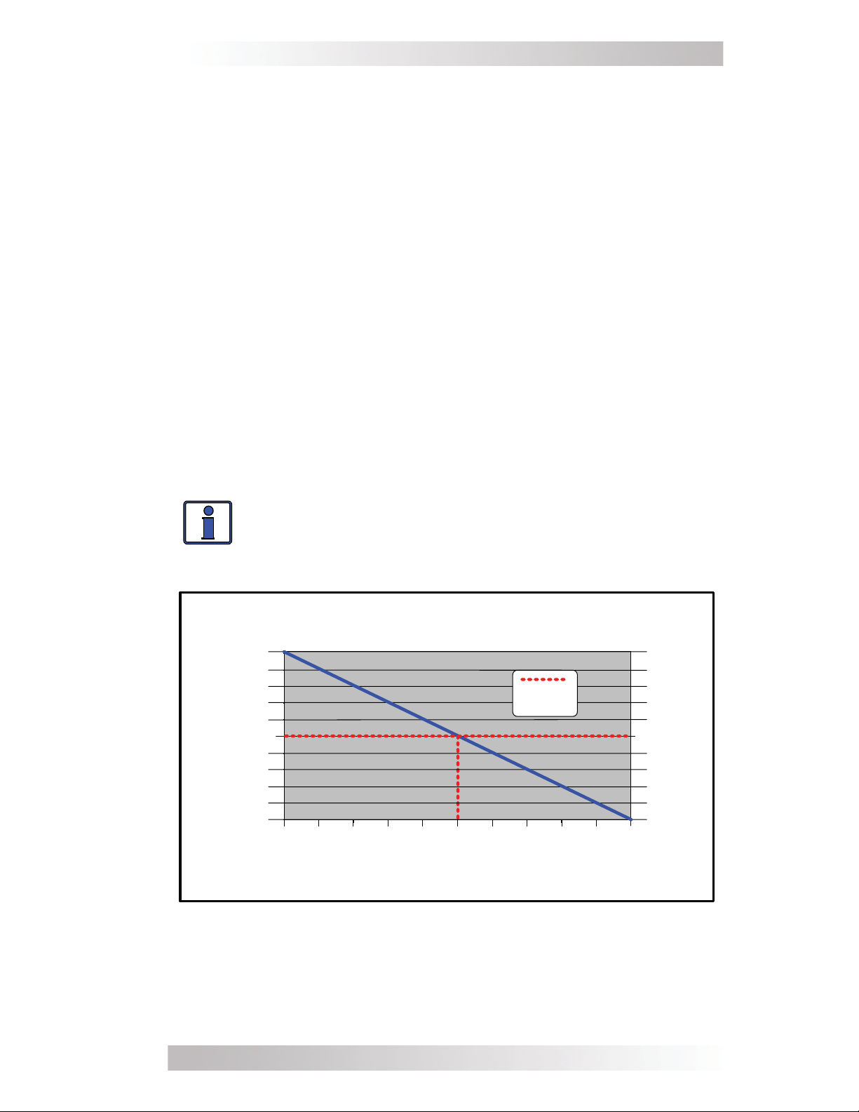
Battery Temperature Sensor Operation - The plug-in Battery Tem-
perature Sensor (BTS) is used to determine the battery temperature
around the batteries. This information allows the multi-stage battery
charger to automatically adjust the battery charge voltages for optimum charging performance and longer battery life.
When the BTS is installed, if the temperature around the BTS is below
77°F (25°C) the absorb and fl oat charge voltage increases. If the
temperature around the BTS is higher than 77°F (25°C), the absorb
and fl oat charge voltage decreases. See Figure 13
much the charge voltage changes (increases or decreases) as the
temperature reading of the BTS changes. For example, the nominal
absorb charge voltage for a fl ooded battery at 77°F (25°C) on a 24-
volt model is 29.2 VDC. If the battery temperature is 95°F (35°C),
the absorb charge voltage would decrease to 28.6 VDC (29.2 VDC
- 0.6 change).
If the temperature sensor is NOT installed, the charge voltages will
not be compensated and the battery will maintain the charge it had
at a temperature of 77°F (25°C). The life of the batteries may be
reduced if they are subjected to large temperature changes when
the BTS is not installed.
to determine how
Info: When the BTS is connected, the battery charger
uses a value of -5mV/°C/Cell from 0-50°C to change the
charge voltage based on temperature.
12VDC units
+0.75 V
0.75
+0.6 V
0.6
+0.45 V
0.45
+0.3 V
0.3
+0.15 V
0.15
No Change
-0.15 V
-0.15
-0 .3V
-0.3
-0.45 V
-0.45
-0 .6V
-0.6
-0.75 V
-0.75
Cha ng e to ba ttery charg ing voltage
Temperature Compensation using BTS
no BT S
connected
0
0C
0 5 10 15 20 25 30 35 40 45 50
32F5C41F
10C
50F
15C
59F
20C
68F
25C
77F
30C
86F
Tem perature reading from BTS
35C
95F
40C
104F
45C
113F
24VDC units
+1.5 V
+1.2 V
+0.9 V
+0.6 V
+0.3 V
No Change
-0 .3V
-0 .6V
-0 .9V
-1 .2V
-1 .5V
50C
122F
Figure 13, BTS Temperature to Charge Voltage Change
© 2010 Magnum Energy, Inc.
27
Page 34

3.0 Operation
Protection Circuitry Operation
The inverter is protected against fault conditions, and in normal usage
it will be rare to see any. However, if a condition occurs that is outside
the inverter’s normal operating parameters, then it will shut down
and attempt to protect itself, the battery bank, and your AC loads. If
there is a condition that causes the inverter to shut down, it may be
one of the conditions listed below. Refer also to the Troubleshooting
section to diagnose and clear the fault.
•
Low Battery - The inverter will shut off whenever the battery
voltage falls to the Low Battery Cut Out (LBCO) level to protect
the batteries from being over-discharged. After the inverter
has reached the LBCO level and turned off, the inverter will
automatically restart after one of the following conditions:
1. AC power is applied and the inverter begins operating as a
battery charger.
2. Battery voltage rises to the Low Battery Cut In (LBCI)
level.
The inverter’s status LED turns off when a low battery fault condition occurs. Refer to Table 5 to determine the LBCO and LBCI
levels for your particular inverter model.
•
High Battery - In the event the battery voltage approaches the
High Battery Cut Out (HBCO) level, the inverter will automatically
shut down to prevent the inverter from supplying unregulated AC
output voltage. The inverter’s status LED turns off when a high
battery fault condition occurs. The inverter will automatically
restart when the battery falls to the High Battery Cut In (HBCI)
level. Refer to Table 5 to determine the HBCO and HBCI levels for
your particular inverter model.
Info: When the BTS is connected, the battery charger
uses a value of -5mV/°C/Cell from 0-50°C to change the
charge voltage based on temperature.
Overload - During Inverter and Standby operation modes, the
•
inverter monitors the DC and AC current levels. In the event
of a short-circuit or an overload condition for more than a few
seconds, the inverter will shut down. To start operating after this
fault, the inverter would need to be restarted (turned back on)
after the inverter’s AC loads are reduced/removed.
Over-temperature - If internal power components begin to
•
exceed their safe operating temperature level, the inverter will
shut down to protect itself from damage. The inverter’s status LED
turns OFF to indicate the over-temperature fault condition. The
inverter will automatically restart after the units cools down.
28
© 2010 Magnum Energy, Inc.
Page 35
3.0 Operation
•
Internal Fault - The inverter continually monitors several inter-
nal components and the processor communications. If a condition
occurs that doesn’t allow proper internal operation, the inverter
will shut down to protect itself and the connected loads. The
inverter will need to be reset to start operating.
Table 5, Inverter Battery Turn On/Off Levels
Inverter Battery
Turn On/Off
Levels
HBCO >15.8 VDC >15.8 VDC >31.6 VDC
HBCI 15.5 VDC 15.5 VDC 31.0 VDC
LBCI ≥12.5 VDC ≥12.5 VDC ≥25.0 VDC
LBCO*
(one minute delay)
LBCO
(immediate)
MM612AE MM1512AE MM1524AE
10.0 VDC
(9.0 - 12.2 VDC
8.5 VDC 8.5 VDC 17.0 VDC
* - adjustable with remote
Inverter Model
10.0 VDC
(9.0 - 12.2 VDC
)
20.0 VDC
(18.0 - 24.4 VDC)
)
Inverter Startup
ON/OFF Switch - The inverter can be turned on and off by lightly
pressing and releasing the Power ON/OFF switch on the front of the
inverter. When the inverter is fi rst connected to the batteries, or when
its automatic protection circuit has turned the inverter off, the ON/OFF
switch will need to be pressed to start the unit. Once the inverter
has been turned on, pressing the Power ON/OFF switch alternately
turns the inverter on and off.
WARNING: The Power ON/OFF control switch does not
turn on or off the charger feature. If AC power (utility or
generator) is connected and qualifi ed on the AC input,
this AC power will also be available on the AC output
and is not controlled by the Power ON/OFF switch.
Status LED Indicator - The status indicator is a green LED (Light
Emitting Diode) that provides information on the operational mode of
the inverter. Watch this indicator for at least 10 seconds to determine
the inverter’s operational condition from the information below:
Inverter Mode
Off - Indicates the inverter is off; there is no AC power from
•
the inverter, utility, or generator at the inverter’s output
terminals.
Blinks On (once every second) - The inverter is on and is
•
using energy from the battery. The inverter is either providing full power to the loads connected to the inverter, or it’s in
Search Mode and ready to supply AC power to the connected
loads.
© 2010 Magnum Energy, Inc.
29
Page 36

3.0 Operation
Protection Mode
There are fi ve fault conditions that will cause the inverter to shut
down: Low Battery, High Battery, Over-temperature, AC Overload,
and Internal faults. If your inverter has shut down, monitor the
status indicator and count the number of blinks that occur every
four seconds to determine the particular reason for the shutdown.
Refer to the Troubleshooting section to help diagnose/clear the
fault condition.
• Blinks on 1 time every four seconds - Low Battery fault.
• Blinks on 2 times every four seconds - High Battery fault.
• Blinks on 3 times every four seconds - Over-temperature
fault.
• Blinks on 4 times every four seconds - AC Overload fault.
• Blinks on 5 times every four seconds - Internal fault.
Charge Mode
The green LED status indicator provides additional
information:
• Blinks off every four seconds - The unit is charging the
batteries connected to the inverter. The external AC power
(utility power or generator) connected to the inverter’s input
is passing through the inverter and is powering the AC loads
connected to the inverter’s output.
Factory Default Settings
The MM-AE Series inverter/charger uses default settings that are adequate for most installations (see Table 6). However, you can adjust
these parameters using Magnum’s optional ME-RC50 remote. The
settings once programmed are saved in non-volatile memory and are
preserved until changed – even if DC power to the inverter is lost
(the ME-RC50 must always be connected). The following information
can help you determine if you need the ME-RC50 remote*.
01 Search Watts: This setting allows you to turn off the power-saving
Search Mode circuitry and to adjust the power level at which the
inverter will “wake up” and start inverting.
02 Low Battery Cut Out: This setting determines when the inverter
will turn off based on low battery voltage. The inverter turns off
automatically after the battery voltage has been below this setting for
more than one minute. This protects the batteries from over-discharge
and the AC loads from unregulated power (brown-outs).
* Visit www.magnumenergy.com for more information.
30
© 2010 Magnum Energy, Inc.
Page 37

3.0 Operation
03 Battery AmpHrs: This setting allows you to input the battery bank
size in amp hours. This provides information to the charger on how
long to charge the batteries in the Absorb Charging stage.
04 Battery Type: This setting identifi es the type of batteries being
used in the system. This provides information to the charger to
determine what voltage level to use to charge the batteries.
05 Charge Rate: T
his setting can be used to turn off the charger, limit
the amount of current that the charger can use (leaving more current
available to power loads); or, to ensure small battery banks are not
overheated because of a charge rate that is too high.
06 VAC Dropout: Sets the minimum AC voltage that must be pres-
ent on the AC input before the unit transfers from Standby Mode to
Inverter Mode. This protects the AC loads from utility outages and
brown-outs.
The ME-RC50 remote also provides the following features:
allows you to enable an equalize charge for certain battery
•
types
displays the inverter/charger’s operating status
•
provides fault information for troubleshooting
•
Table 6, Inverter Default Settings
Function Default Settings
Search Watts 5W
LowBatCutOut 10.0 VDC (MM1524AE - 20.0 VDC)
Battery AmpHrs
Battery Type
(MM1524AE - Bulk = 29.2 VDC, Float = 26.8 VDC)
Charge Rate 100%
VAC dropout 80VAC
(Absorb Time = 120 minutes)
Flooded - Liquid Lead Acid
(Bulk = 14.6 VDC, Float = 13.4 VDC)
400 AmpHrs
© 2010 Magnum Energy, Inc.
31
Page 38

4.0 Maintenance and Troubleshooting
4.0 Maintenance and Troubleshooting
Recommended Inverter and Battery Care
The MM-AE Series inverter/charger is designed to provide you with
years of trouble-free service. Even though there are no user-serviceable parts, it is recommended that every 6 months you perform the
following maintenance steps to ensure optimum performance and
extend the life of your batteries.
WARNING: Prior to performing these checks, switch
both the AC and DC circuits OFF.
• Visually inspect the batteries for cracks, leaks, or swelling –
replace if necessary.
• Use baking soda to clean and remove any electrolyte spills or
buildups.
• Check and tighten all battery holddown clamps.
• Clean and tighten (10 to 12 foot-pounds) all DC terminals
(battery and inverter) and connecting cables.
• Check and fi ll battery water levels (Liquid Lead Acid batteries
only).
• Check individual battery voltages (replace those that vary
more than 0.3 VDC of each other).
• Check all cable runs for signs of chafi ng – replace if necessary.
• Check the inverter’s cooling vents – clean as necessary.
Resetting the Inverter
Under some fault conditions (i.e., an internal fault), the inverter will
need to be reset.
To reset the inverter:
Press and hold the Power ON/OFF pushbutton for approximately
1.
15 seconds, or until the status LED comes on and fl ashes rapidly
(see Figure 2, Items 1 and 2).
Release the Power ON/OFF pushbutton once the rapid fl ashing
2.
has begun. The status LED will go off.
Press the Power ON/OFF pushbutton again to turn the
3.
inverter on.
Info: The Power ON/OFF pushbutton is a small momentary
type switch which operates by lightly pressing and
releasing.
32
© 2010 Magnum Energy, Inc.
Page 39

4.0 Maintenance and Troubleshooting
Troubleshooting
The MM-AE Series inverter/charger is a fairly simple device to troubleshoot. There are only two active circuits (AC and DC), as well as a
charging circuit. The following chart is designed to help you quickly
pinpoint the most common inverter and charger faults.
Table 7, Troubleshooting Guide
Symptom Possible cause Recommended Solution
Low Battery Voltage
(the status indicator
blinks on 1 time every
4 secs)
High Battery Voltage
(the status indicator
blinks on 2 times
every 4 secs)
Over-temperature
condition
(the status indicator
blinks on 3 times
every 4 secs)
AC Overload
(the status indicator
blinks on 4 times
every 4 secs)
Internal fault
(the status indicator
blinks on 5 times
every 4 secs)
The battery voltage level has dropped
below the Low Battery Cut Out
(LBCO) set-point for more than one
minute (10.0VDC = LBCO default
setting).
The battery voltage is above 15.5
VDC. The inverter automatically
resets and resumes operation when
the battery voltage drops below 15.5
VDC.
The internal temperature of the
inverter has risen above acceptable
limits; caused by loads too great for
the inverter to operate continuously,
or by lack of ventilation to the
inverter. When the unit has cooled, it
will automatically reset and resume
operation.
The inverter has turned off because
the connected loads are larger than
the inverters output capacity or the
output wires are shorted.
This fault occurs when an internal
fault is detected.
Battery voltage is too low. Check fuses/
circuit-breakers and cable connections.
Check battery voltage at the inverter's
terminals. Your batteries may need
to be charged, this fault condition will
automatically clear when the battery
voltage exceeds 12.5VDC.
This condition usually occurs only when
an additional charging source (alternator,
solar panels or other external charging
sources) is used to charge the battery
bank. Reduce or turn off any other
charger to the inverter batteries to allow
the voltage level to drop.
Reduce the number of electrical loads
that you are operating, this will avoid a
repeat Over-temp shutdown if the cause
was too many loads for the ambient
Check ventilation around the inverter,
ensure cool air is available to pass-thru
the inverter.
Reduce the AC loads connected to the
inverter or remove all AC output wiring
and restart the inverter.
To clear this fault, an inverter reset
is required. Remove DC power to the
inverter or press and hold down the
power switch on the inverter for 15
seconds (until the green Status LED
comes on). If this fault does not clear, the
unit will need to be serviced.
Inverter's status light
is off.
AC input won't connect
(AC IN on remote
blinks)
Appliances turn off
and on; or there is low
AC output power.
Inverter AC output
voltage is too low or
too high when using
an AC voltmeter.
While charging, the
DC charge voltage is
higher or lower than
expected.
Inverter is switched OFF or there is
no DC voltage (battery) connected to
inverter.
The incoming AC voltage will not
be accepted if it is below the VAC
Dropout setting (80VAC = VAC
Dropout default setting).
Loose AC output connections. Tighten AC output connections.
Loose / corroded battery cables. Clean and tighten all cables.
Wrong type of voltmeter used (will
display 90 VAC to 130 VAC depending
on the battery voltage).
If the Battery Temperature Sensor is
installed, it will increase or decrease
the DC voltage level depending on
temperature around the battery
sensor.
© 2010 Magnum Energy, Inc.
Switch the inverter ON. Connect a battery
with correct voltage to the inverter.
Check the incoming AC voltage to the
input of the inverter, ensure it is present
and above the VAC dropout level.
Most meters are made to read Average
AC voltage. The AC output of the MM is a
"modifi ed" waveform which requires using
a “true” RMS voltmeter to correctly read
the output voltage.
This is normal.
33
Page 40

5.0 Specifi cations
5.0 Specifi cations
Table 8, MM-AE Series Specifi cations
MODEL MM612AE MM1512AE MM1524AE
Inverter Specifi cations
Input battery voltage range 9 to 16 VDC 9 to 16 VDC 18 to 32 VDC
Nominal AC output voltage 120 VAC +/- 5%
Output frequency and accuracy 60 Hz +/- 0.1 Hz
1msec surge current (amps AC) 27 42 45
100msec surge current (amps AC) 11 23 24
5 sec surge power (real watts) 1100 2100 2650
10 sec surge power (real watts) 1050 1900 2575
30 sec surge power (real watts) 1000 1750 2500
5 min surge power (real watts) 950 1550 2350
30 min surge power (real watts) 675 1525 1900
Continuous power output at 25° C 600 VA 1500 VA 1500 VA
Maximum input battery current 80 ADC 200 ADC 100 ADC
Inverter effi ciency (peak) 95% 95% 91%
Transfer time 16 msecs
AC transfer capability 7A 12A 12A
Search mode (typical) 3 watts 6 watts 4 watts
No load (120 VAC output, typical) 10 watts 18 watts 9 watts
Waveform Modifi ed Sine Wave
Charger Specifi cations
Continuous output at 25° C 30 ADC 70 ADC 35 ADC
Charger effi ciency 85% 88% 88%
Power factor > 0.95
Input current at rated output (amps AC) 4 9 9
Battery temperature compensation Yes, 15 ft Battery Temp Sensor standard
General Features and Capabilities
Protection circuitry Low/High Battery, Over-temp & Overload
Corrosion protection PCB's conformal coated, powder coated chassis
Output circuit breaker 7A switchable 12A switchable 12A switchable
Input circuit breaker 8 AAC 20 AAC 20 AAC
Internal cooling Yes, 0 to 59 cfm variable speed
Optional remotes available MM-RC or ME-RC50
UL listing NA
Environmental Specifi cations
Operating temperature -20° C to +60° C (-4° F to 140° F)
Non-operating temperature -40° C to +70° C (-40° F to 158° F)
Operating humidity 0 to 95% RH non-condensing
Physical Specifi cations
Dimensions (L x W x H) 16.6"x 8.4”x 4.7” (42cm x 21cm x 12cm)
Mounting Shelf or wall (no vents facing downward or upward)
Weight 16 lbs. (7.3 kg) 22 lbs. (10 kg) 22 lbs. (10 kg)
Shipping weight 18 lbs. (8.2 kg) 24 lbs. (10.9 kg) 24 lbs. (10.9 kg)
Specifi cations @ 25° C - Subject to change without notice
34
© 2010 Magnum Energy, Inc.
Page 41

Appendix A - Optional Equipment and Accessories
Appendix - Optional Equipment and Accessories
The following Magnum Energy components are available for use
with the MM-AE Series inverter/charger. Some of these items are
required depending upon the intended use of the inverter.
Smart Battery Combiner
The Smart Battery Combiner (ME-SBCTM) is designed to monitor and
charge a second battery using a portion of the current that is charging
the main battery. The ME-SBC eliminates a signifi cant voltage drop,
and provides automatic turn-on and turn-off based on adjustable voltage set-points. This allows different batteries to be charged from a
single charging source, and prevents overcharging/undercharging.
Basic Remote Control
The ME-RC50 Remote Control Panel is simple to use; an LCD screen
and “at a glance” LEDs display complete inverter/charger status. Soft
keys provide simple access to menus and a rotary encoder knob allows you to scroll through and select a wide range of settings.
Auto Generator Start Controller
The ME-AGS-N Automatic Generator Start controller (Network version) is designed to automatically start your generator based on low
battery condition or high temperature.
an input voltage jumper (for 12, 24, and 48 volt battery banks) and
a 4-position DIP (Dual In-line Package) switch which provides the
ability to change the relay timing confi gurations to allow compatibility
with a wider range of generators.
The AGS controller includes
Battery Monitor Kit
The ME-BMK Battery Monitor Kit is a single battery bank amp-hour
meter
mation to let you know how much energy you have available and
let you plan your electrical usage to ensure the battery is not being
over-discharged. The ME-BMK-NS version does not include
– order the ME-BMK to receive a 500A/50mv DC shunt.
Fuse Block/Fuses
The Magnum Fuse/Fuse-blocks are used to protect the battery bank,
inverter, and cables from damage caused by DC short circuits and
overloads. They include a slow-blow fuse with mounting block and
protective cover. The 125 and 200 amp models use an ANL type fuse
and the 300 and 400 amp models use a Class-T fuse.
DC Load Disconnect
The MM-DCLD (DC Load Disconnect) pigtail adapter is designed to
provide a means to DISABLE the inverter function when a 12 volt
DC signal is removed.
Ignition Switch Activate
The MM-ISA is a pigtail adapter designed to automatically ENABLE
the inverter function when a 12 volt DC signal is supplied.
that monitors the condition of the battery and provides infor-
a DC shunt
© 2010 Magnum Energy, Inc.
35
Page 42

Appendix B - Battery information
Appendix B - Battery Information
Battery Bank Sizing
The size of the battery bank determines how long the inverter can
power the AC loads without recharging. The larger the battery bank,
the longer the run time. Size your battery bank to the system’s AC
load requirements and the length of time required to run the load
from the batteries. In general, the battery bank should not be discharged more than 50%.
Battery Types
Batteries are available in different sizes, amp-hour ratings, voltage,
and chemistries; they also come in liquid or gel, vented or nonvented, etc. They are also available for starting applications (such
as an automobile starting battery) and deep discharge applications.
Only the deep cycle types are recommended for inverter applications.
Choose the batteries best suited for the inverter installation and cost.
Use only the same battery type for all batteries in the bank. For best
performance, all batteries should be from the same lot and date. This
information is usually printed on a label located on the battery.
Battery Confi guration
The battery bank must be wired to match the inverter’s DC input voltage specifi cations. In addition, the batteries can be wired to provide
additional run time. The various wiring confi gurations are:
Series Wiring
Wiring batteries in a series increases the total battery bank output
voltage. A series connection combines each battery in a string until the
voltage matches the inverter’s DC requirement. Even though there
are multiple batteries, the capacity remains the same. In the example
below (Figure 14), two 6 VDC/200 AHr batteries are combined into
a single string – resulting in a 12 VDC/200 AHr bank.
ov erc urr ent protection
To
6 volts
(200 AHrs )
6 volts
(200 AHrs)
12 VDC
Inverter
12 volt batt er y bank (tot al capacit y = 200 AHrs)
Figure 14, Series Battery Wiring
36
© 2010 Magnum Energy, Inc.
Page 43

Appendix B - Battery Information
Parallel Wiring
Wiring the batteries in parallel increases the total run time the batteries can operate the AC loads. A parallel connection combines
overall battery capacity by the number of batteries in the string. Even
though there are multiple batteries, the voltage remains the same.
In the example below (Figure 15), four 12 VDC/100 AHr batteries
are combined into a single 12 VDC/400 AHr battery bank.
12 volts
(100 AHrs )
12 volts
(100 AHrs )
12 volts
(100 AHrs )
12 volts
(100 AHrs )
12 volt battery b ank (tot al capacity = 400 AHrs)
over c urrent
protec tion
To
12 VDC
Inverter
Figure 15, Parallel Battery Wiring
Series-Parallel Wiring
A series-parallel confi guration increases both voltage (to match the
inverter’s DC requirements) and capacity (to increase run time for
operating the loads) using smaller, lower-voltage batteries. In the
example below (Figure 16), four 6 VDC/200 AHr batteries are combined into two strings resulting in a 12 VDC/400 AHr battery bank.
over c urrent
protec tion
To
12 VDC
Inverter
String 1
String 2
6 volts
(200 AHrs)
6 volts
(200 AHrs)
12 volt bat tery bank (total capacity = 400 AHrs)
6 volts
(200 AHrs)
6 volts
(200 AHrs)
Figure 16, Series-Parallel Battery Wiring
© 2010 Magnum Energy, Inc. 37
Page 44
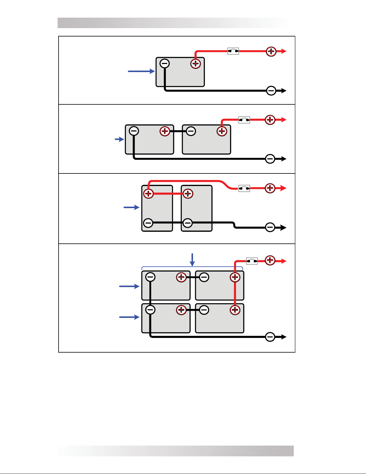
Appendix B - Battery Information
overcurrent
protection
String
(12 VDC @ 100 AH)
12 vol t batte ry bank (one string of one 12-v ol t batte r y)
Series String
(6 VDC + 6 VDC)
12 volt battery bank (one string of two 6-volt batteries wired in series)
Parallel String
(100 AH + 100 AH)
6 VDC
battery
(200 AH )
12 VDC
battery
(100 AH )
12 VDC
battery
(100 AH )
12 VDC
battery
(100 AH )
6 VDC
battery
(200 AH )
to 12 V D C
(total capacity
= 100 AH)
overcurrent
protection
to 12 V D C
(total capacity
= 200 AH)
overcurrent
protection
to 12 V D C
(total capacity
= 200 AH)
inverter
inverter
inverter
12 vol t batte ry bank (paral l el two 12-vol t batter i e s)
Pa r a lle l String (200 AH + 200 AH)
Series String
(6 VDC + 6 VDC)
Series String
(6 VDC + 6 VDC)
12 volt battery bank (two strings of two 6-volt batteries wired in series and
6 VDC
battery
(200 AH )
6 VDC
battery
(200 AH )
connected in parallel)
6 VDC
battery
(200 AH )
6 VDC
battery
(200 AH )
overcurrent
protection
(total capacity
Figure 17, Battery Bank Wiring Examples (12 volt)
to 12 VDC
inverter
= 400 AH)
38
© 2010 Magnum Energy, Inc.
Page 45
Appendix B - Battery Information
Series String
(12 VDC + 12 VDC)
24 volt battery bank (one string of two 12 -volt batteries wired in series )
12 VD C
battery
(100 A H)
Series String
(6 VDC + 6 VDC
+ 6 V DC + 6 VD C)
24 volt battery bank (one string of four 6-volt batteries wired in series )
6 VD C
battery
(200 AH )
(200 AH)
Parallel String (100 AH + 100 AH)
Series String
(12 VDC + 12 VDC)
Series String
(12 VDC + 12 VDC)
12 VD C
battery
(100 A H)
12 VD C
battery
(100 A H)
6 VD C
battery
12 VD C
battery
(100 A H)
6 VD C
battery
(200 AH )
12 VD C
battery
(100 AH)
12 VD C
battery
(100 A H)
6 VD C
battery
(200 AH )
overcurrent
protection
overcurrent
protection
overcurrent
protection
to 24 VD C
inverter
(total capacity
= 100 A H)
to 24 VD C
inverter
(total capacity
= 200 A H)
to 24 V D C
inverter
(total capacity
= 200 AH)
24 volt battery bank (two strings of two 12-volt batteries wired in series and connected in parallel )
Parallel String (200 AH + 200 AH)
Series String
(6 VDC + 6 VDC
+ 6 VD C + 6 VD C)
6 VD C
battery
(200 AH )
6 VD C
battery
(200 AH)
6 VD C
battery
(200 AH )
6 VD C
battery
(200 AH )
Series String
(6 VDC + 6 VDC
+ 6 VD C + 6 VD C)
24 volt battery bank (two strings of four 6-volt batteries wired in series and connected in parallel )
6 VD C
battery
(200 A H)
6 VD C
battery
(200 AH)
6 VD C
battery
(200 A H)
6 VD C
battery
(200 A H)
overcurrent
protection
(total capacity
to 24 VD C
inverter
= 400 A H)
Figure 18, Battery Bank Wiring Examples (24-volt)
© 2010 Magnum Energy, Inc.
39
Page 46

Appendix C - Warranty/Service Information
Appendix C - Warranty/Service Information
24 Month Limited Warranty
Magnum Energy, Inc., warrants this MM-AE Series Inverter/Charger
to be free from defects in material and workmanship that result in
product failure during normal usage, according to the following terms
and conditions:
1. The limited warranty for the product extends for 24 months
beginning from the product’s original date of purchase.
2. The limited warranty extends to the original purchaser of the
product and is not assignable or transferable to any subsequent
purchaser.
3. During the limited warranty period, Magnum Energy will repair or
replace (with factory new or rebuilt replacement items) at Magnum
Energy’s option any defective parts, or any parts that will not properly
operate for their intended use – if such repair or replacement is
needed because of product malfunction or failure during normal
usage. The limited warranty does not cover defects in appearance
(cosmetic or decorative), or any structural or non-operative parts.
Magnum Energy’s limit of liability under the limited warranty shall be
the actual cash value of the product at the time the original purchaser
returns the product for repair, determined by the price paid by the
original purchaser. Magnum Energy shall not be liable for any other
losses or damages.
4. Upon request from Magnum Energy, the original purchaser must
prove the product’s original date of purchase by a dated bill of sale,
itemized receipt.
5. The original purchaser shall return the product prepaid to Magnum
Energy in Everett, WA. After the completion of service under this
limited warranty, Magnum Energy will return the product prepaid to
the original purchaser via a Magnum selected non-expedited surface
freight within the contiguous United States and Canada; this excludes
Alaska and Hawaii.
6. If Magnum repairs or replaces a product, its warranty continues for
the remaining portion of the original warranty period or 90 days from
the date of the return shipment to the original purchaser, whichever
is greater. All replaced products and parts removed from repaired
products become the property of Magnum Energy.
7. This limited warranty is voided if:
• the product has been modifi ed without authorization
• the serial number has been altered or removed
• the product has been damaged through abuse, neglect
accident, high voltage, or corrosion
• the product was not installed and operated according to the
owner’s manual
BEFORE RETURNING ANY UNIT, CONTACT MAGNUM ENERGY FOR A
RETURN MATERIAL AUTHORIZATION (RMA) NUMBER.
40
© 2010 Magnum Energy, Inc.
Page 47

Appendix C - Warranty/Service Information
How to Receive Repair Service
If your product requires warranty service or repair, contact either:
1. An Authorized Service Center as listed on the Magnum Energy
website at www.magnumenergy.com/servicecenters.htm; or
2. Magnum Energy, Inc. at:
Telephone: 425-353-8833
Fax: 425-353-8390
Email: warranty@magnumenergy.com
If returning the product directly to Magnum Energy for repair, you
must:
return the unit in the original, or equivalent, shipping container
•
receive a Return Materials Authorization (RMA) number from
•
the factory prior to the return of the product to Magnum Energy for repair
place RMA numbers clearly on the shipping container or on the
•
packing slip.
When sending your Product for service, please ensure it is properly
packaged. Damage due to inadequate packaging is not covered
under warranty. We recommend sending the Product by traceable
or insured service.
© 2010 Magnum Energy, Inc.
41
Page 48

Magnum Energy, Inc.
2211 West Casino Rd.
Everett, WA 98204
Phone: (425) 353-8833
Fax: (425) 353-8390
Web: www.magnumenergy.com
PN: 64-0035 Rev A
© 2010 Magnum Energy, Inc.
 Loading...