

Page 1
ME-SBC
TM
Smart Battery Combiner
TM
Owner’s Manual
Page 2
Disclaimer of Liability
Since the use of this manual and the conditions or methods of installation,
operation, and maintenance of the ME-SBC
TM
are beyond the control of Magnum
Energy Inc., this company does not assume responsibility and expressly
disclaims liability for loss, damage or expense, whether direct, indirect,
consequential or incidental, arising out of or anyway connected with such
installation, operation, use, or maintenance.
Due to continuous improvements and product updates, the images shown in
this manual may not exactly match the unit purchased.
Restrictions on Use
The ME-SBCTM shall not be used in connection with life support systems, life
TM
saving or other medical equipment or devices. Use of the ME-SBC
with this
particular equipment is at your own risk.
IMPORTANT PRODUCT SAFETY INSTRUCTIONS
This manual contains important safety instructions that must be followed
during the installation and operation of this product. Read all instructions
and safety information contained in this manual before installing or using
this product.
WARNINGS:
• All electrical work must be performed in accordance with local, state and
federal electrical codes.
• This product is designed for indoor / compartment installation. It must not
be exposed to rain, snow, moisture or liquids of any type.
• Use insulated tools to reduce the chance of electrical shock or accidental
short circuits.
• Remove all jewelry such as rings, watches, bracelets, etc., when installing
or performing maintenance on the ME-SBC
TM
system.
• Always disconnect the batteries or energy source prior to installing or performing maintenance on the ME-SBC
TM
system.
Safety Symbols
To reduce the risk of electrical shock, fi re, or other safety hazard, the fol-
lowing safety symbols have been placed throughout this manual to indicate
dangerous and important safety instructions.
WARNING: This symbol indicates that failure to take a specifi ed
action could result in physical harm to the user.
CAUTION: This symbol indicates that failure to take a specifi ed ac-
tion could result in damage to the equipment.
Info: This symbol indicates information that emphasizes or supple-
ments important points of the main text.
ii ©2009 Magnum Energy Inc.
Page 3

List of Sections
1.0 Introduction ............................................................................. 1
2.0 Installation ............................................................................... 3
TM
3.0 Adjusting the ME-SBC
.......................................................... 11
4.0 Limitations of Throughput ..................................................... 12
5.0 LED Indicators ........................................................................ 13
6.0 Troubleshooting .................................................................... 14
7.0 Specifi cations ......................................................................... 15
8.0 Limited Warranty ................................................................... 16
List of Tables
Table 2-4, Recommended Wires Sizes for 3% loss ......................... 5
Table 3-2, Battery Combining Operation ....................................... 12
Table 5-1, LED Indicators ............................................................. 13
Table 6-1, Troubleshooting Table ................................................ 14
Table 7-1, Specifications .............................................................. 15
List of Figures
Figure 1-1, Front Panel Interface ................................................... 2
Figure 2-1, ME-SBC
Figure 2-2, Power Terminal Block ................................................... 4
Figure 2-3, Accessories Terminal Block .......................................... 4
Figure 2-5, ME-SBC
Figure 2-6, Solenoid Drive .............................................................. 8
Figure 2-7, Remote Volt Sense ..................................................... 10
Figure 3-1, Battery Combining Setpoints ...................................... 11
Figure 3-2, Battery Combining Operation ..................................... 12
©2009 Magnum Energy Inc. iii
TM
Dimensions ................................................... 3
TM
- 25 Amp Combiner Mode .............................. 6
Page 4

Introduction
1.0 Introduction
The Magnum Smart Battery CombinerTM (ME-SBCTM) is designed to monitor
and charge a second battery using a portion of the current that is charging
a main battery.
The ME-SBC
circuit that eliminates a signifi cant voltage drop and provides automatic turn
on and off based on adjustable voltage setpoints; allowing different batteries
to be charged from a single charging source and preventing over or under
charging.
TM
uses MOSFETs, which is a bidirectional electronic switch, control
1.1 Product Features
• Compatible with 12 or 24 volt Systems
• Very easy install and setup
• Auto-detecting input voltage (12, 24V)
• Transfers up to 25 Amps
• Solenoid drive for ampacity requirement greater than 25 Amps
• Over-temp shutdown
• Wide voltage range allows maximum charging fl exibility
• Adjustable Voltage settings
• Over-current shutdown
• Front panel LED’s for status and troubleshooting
• Reverse polarity protection
Virtually zero voltage loss
•
Bidirectional charging
•
Sense lead for long run applications
•
1 ©2009 Magnum Energy Inc.
Page 5
1
3
Introduction
2
5
4
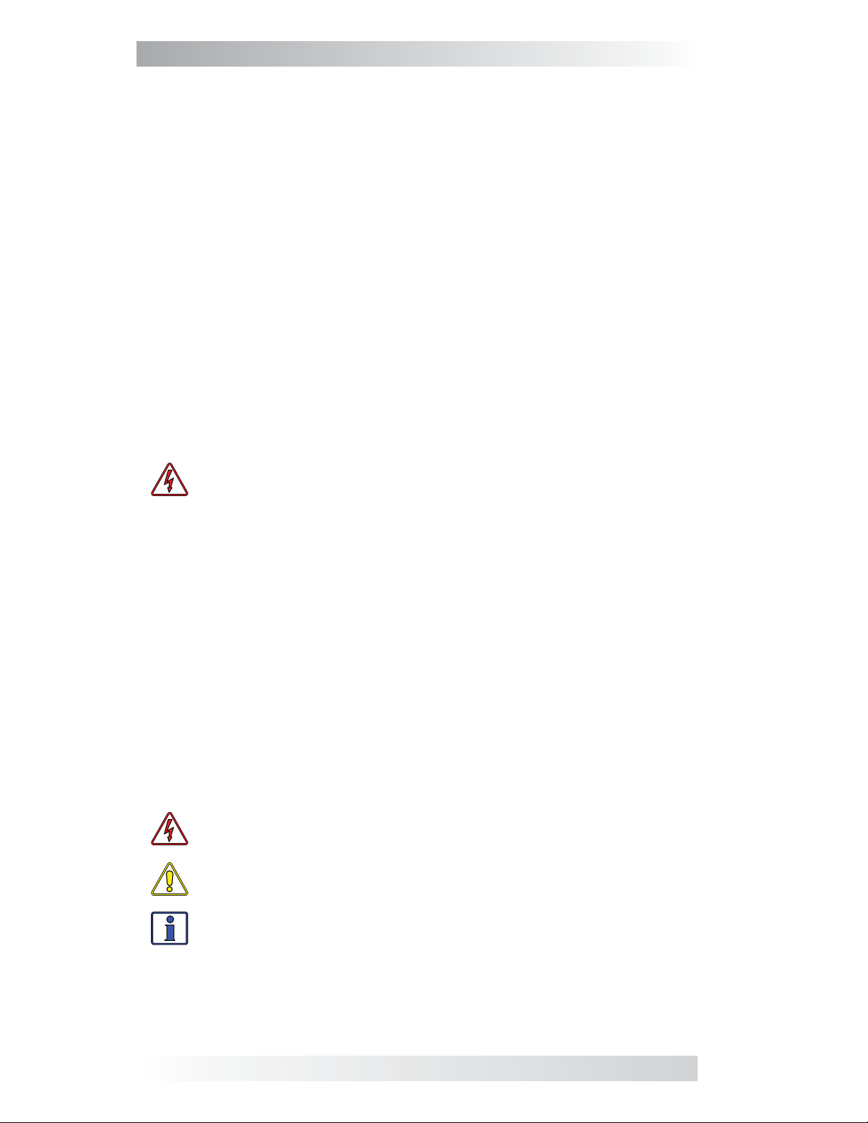
Figure 1-1, Front Panel Interface
1.2 Front Panel
1. LED Indicators - The at-a-glance LEDs provide status and operation in
a straightforward way.
2. Adjustable Voltage Settings - Three dials for adjusting the CONNECT
VOLTS DC and the LOW and HIGH VDC DISCONNECT settings for maximum
charging fl exibility.
3. Reset Switch - Performs a full reset of the ME-SBC
4. Power Terminal Block- The oversized, removable terminal block allows
fast and easy wire connections from the battery banks and makes provision
for large wires to accomodate for long wire runs.
5. Accessories Terminal Block - Easy wire terminal block adds functionality
to drive a solenoid, or run a seperate Remote Voltage Sense line to
compensate for systems with long wire runs.
TM
.
©2009 Magnum Energy Inc. 2
Page 6
Installation
2.0 Installation
Before installing the ME-SBCTM, read this entire section to be aware of all aspects of the installation; then you can thoroughly plan the details to ensure
the overall system requirements are accomplished.
To assist you in planning and designing your installation; you should review
the basic system diagram shown in Figure 2-2 and Figure 2-3.
Info: Installations should be performed by qualifi ed personnel, such
as a licensed or certifi ed electrician. It is the installer’s responsibility
to determine which safety codes apply and to ensure that all applicable installation requirements are followed.
Info: Review the “Important Product Safety Information” on the
front inside cover page before any installation.
2.2 Location and Mounting
Select a location that is dry and away from extreme temperatures to mount
TM
the ME-SBC
; using the supplied #8 x 3/4 screws (x4).
access the three adjustment dials, to view the LEDs
blocks
; refer to Figure 2-1 for dimensions on the ME-SBCTM.
TM
CAUTION: Do not mount the ME-SBC
ment or in an area
TM
ME-SBC
and cause shorting or corrosion. The internal circuit board
where water or any other liquid can enter the
in a closed battery compart-
Allow ample room to
and to access the terminal
is conformal coated to help prevent corrosion. However, a failure that
is caused by corrosion is not covered by the warranty.
WARNING: This device is not tested for Ignition Protection. Do not
install this device in a gasoline engine room or any other area that
requires an ignition protection rating.
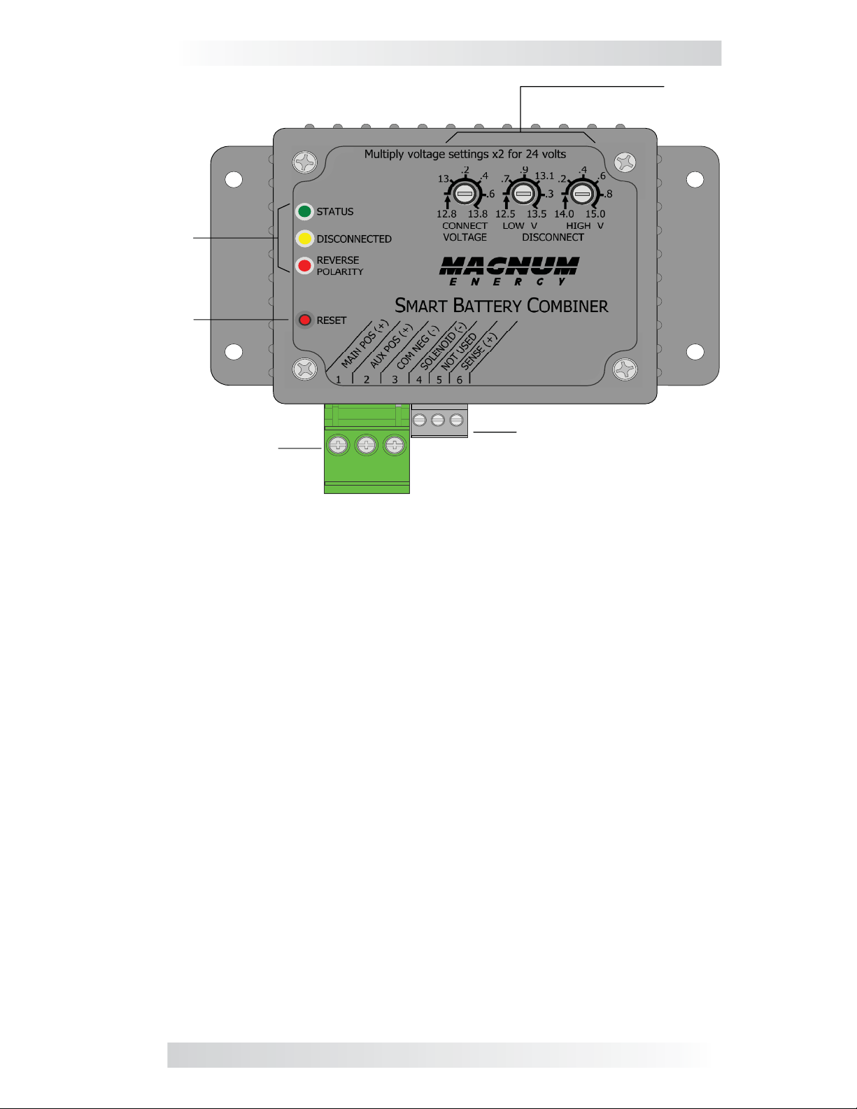
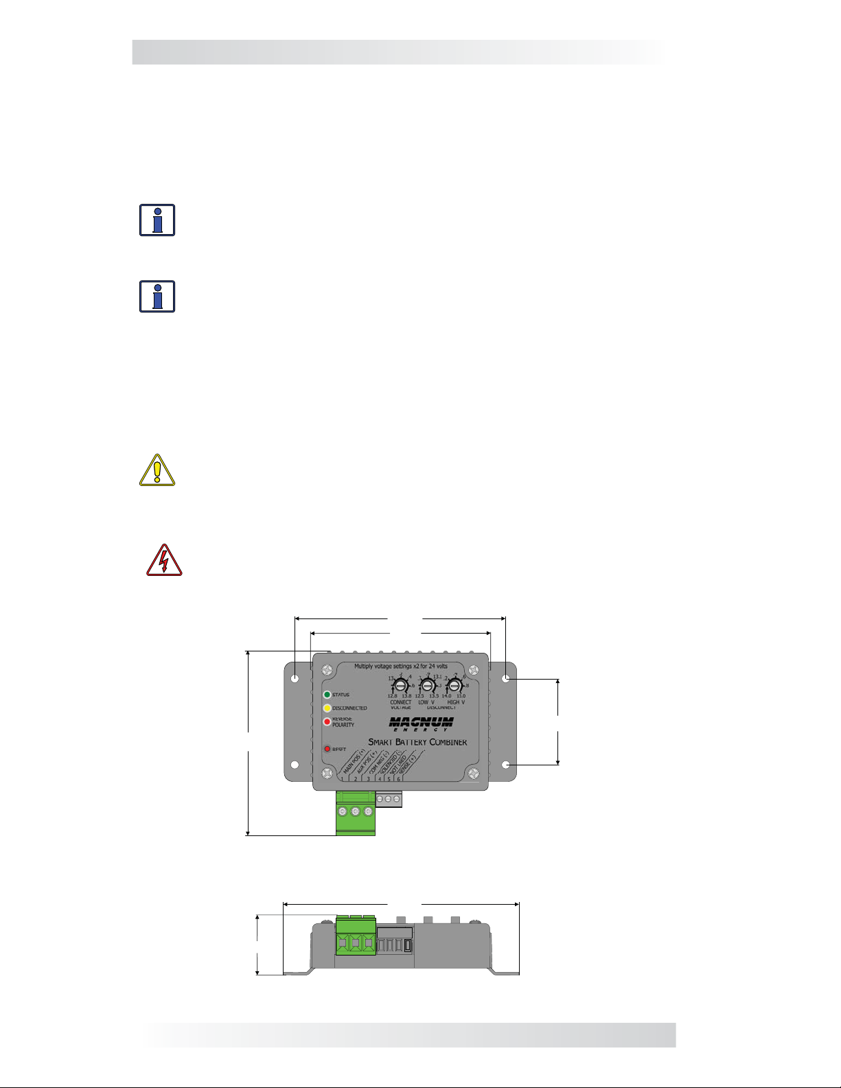
4.9"
4.2"
2.0"
4.2"
5.4"
1.4"
Figure 2-1, ME-SBCTM Dimensions
3 ©2009 Magnum Energy Inc.
Page 7

Installation
2.3 Connections
Please refer to the diagrams below for connectivity information.
ME-SBC™
To Main Battery
Positive
To Auxiliary
Battery Positive
Figure 2-2, Power Terminal Block
ME-SBC™
The Power
Termi nal B lock is
removable and
each port accepts
12 to 8 AWG wire
To Common
Battery
Negative
The Accessories
Termi nal B lock is
removable and each
port accepts
18 to 12 AWG wire
Remote Voltage Sense
Not Used
Negative to the
Solenoid Drive
Figure 2-3, Accessories Terminal Block
2.4 Confi gurations
The ME-SBCTM can be confi gured to accomplish battery combining in a simple,
fl exible way. There are two methods and they are as follows:
25 Amp Combiner - This confi guration is simple to install and use. The
3-wire connection system is similar to connection methods used by other
battery combining products. One of the the advantages of this controller is
the advanced combining options that are available to the installer. It is best
to choose this method when designing systems where 25 amps or less are
required. For this confi guration see Figure 2-5.
Solenoid Drive - If more battery combining capacity (or Ampacity) is required
the installer can employ any solenoid, so long as the coil of that solenoid
consumes less than 2 Amps. The source that provides power to the solenoid
must not exceed 40 VDC. This circuit switches DC Negative to the accessory
terminal block position #4 entitled Solenoid (-). For this confi guration please
see Figure 2-6.
©2009 Magnum Energy Inc. 4
Page 8

Installation
2.4.1 ME-SBCTM Wiring Connections - 25 Amp
CAUTION: Before connecting any wires, turn off any battery charger
and loads that are connected to the battery banks that the ME-SBCTM
will be combining.
Info: If installing in a boat, RV or truck, ensure the conductors
passing through walls, bulkheads or other structural members are
protected to minimize insulation damage such as chafi ng; which can
be caused by vibration or constant rubbing.
The ME-SBC
TM
should now be mounted if not please refer to section 2.2.
During installation please refer to Figures 2-5 during the following steps:
TM
1. Unplug the Power Terminal Block from ME-SBC
and ensure the open-
ings are unscrewed enough to allow the wires to be inserted.
1
2. Select and connect an appropriately sized red wire
from terminal #1
- MAIN POS (+) on the Power Terminal Block to the positive terminal of
the Main Battery.
3. Select and Connect an appropriately sized red wire with a white stripe
from terminal #2 - AUX POS (+) on the Power Terminal Block to the positive
terminal of the Auxiliary Battery.
1
4. Select and connect an appropriately sized a black wire
from terminal #3
- COM NEG (-) on the Power Terminal Block to the Negative bus-bar or
vehicle chassis.
Info: The Negative busbar must connect the negative terminals on
the Main and Auxiliary Batteries together.
5. When all the connections are made and checked, plug the Power Terminal
TM
Block into the ME-SBC
to supply DC power.
Info: If there is a miswire in the system the “Reverse Polarity” LED
will be on. Correct the polarity of the wires connected to the Main
Terminal.
1
TM
6. Immediately after applying DC power, the LED’s on the ME-SBC
should
come on as the unit goes through a power-up self-test. After the initial self-
test completes, the Status LED should be illuminated. If so, your ME-SBC
TM
is now ready for set-up; if not, please refer to the troubleshooting section.
10 ft 15 ft 20 ft 30 ft
12 V
10 AWG 8 AWG not recommended not recommended
24 V 12 AWG 12 AWG 10 AWG 8 AWG
Table 2-4, Recommended Wires Sizes for 3% loss
note 1 : The wires connected to #1 - MAIN POS (+), #2 - AUX POS (+)
and #3 - COM NEG (-) should be sized for 30 amps and the same size.
The battery positive #1 - MAIN POS (+) and #2 - AUX POS (+) lines
should be protected with a 30 Amp fast blow fuse. Wire size should be
appropriate for the application.
5 ©2009 Magnum Energy Inc.
Page 9

Installation
Magnum Energy
Inverter/Charger
ME-RC
Remote Control
PWR
FA ULT
Inverting
CHG
DC 12.6V 5A
INV
ON/OFF
CHARG ER
ON/OFF
AGS MET ER SETUPSHOREINVERTER
TECH
ME-SBC
S m art Battery Co m bin er
SELECT
U
S
E
F
T
S
C
S
L
A
Main
Battery Bank
A uxiliary (A U X)
Battery Bank
Negative Bus-bar
Figure 2-5, ME-SBC - 25 Amp Combiner Mode
©2009 Magnum Energy Inc. 6
Page 10

Installation
2.4.2 ME-SBCTM Wiring Connections - Solenoid Drive
CAUTION: Before connecting any wires, turn off any battery charger
and loads that are connected to the
will be combining.
Info: If installing in a boat, RV or truck, ensure the conductors
passing through walls, bulkheads or other structural members are
protected to minimize insulation damage such as chafi ng; which can
be caused by vibration or constant rubbing.
battery banks that the ME-SBCTM
The ME-SBC
TM
should now be mounted, if not please refer to section 2.2.
During installation please refer to Figures 2-6 during the following steps:
TM
1. Unplug the Power Terminal Block from ME-SBC
and ensure the open-
ings are unscrewed enough to allow the wires to be inserted.
1
2. Select and connect an appropriately sized red wire
from terminal #1 -
MAIN POS (+) on the Power Terminal Block to the positive terminal of
the Main Battery.
1
3. Select and connect an appropriately sized red with white stripe wire
from
terminal #2 - AUX POS (+) on the Power Terminal Block to the positive
terminal of the Auxiliary Battery.
1
4. Select and connect an appropriately sized black wire
from terminal #3
- COM NEG (-) on the Power Terminal Block to the negative busbar or
vehicle chassis.
Info: The negative busbar must connect the negative terminals on
the Main and Auxiliary Batteries together.
2
5. Use an appropriately sized wire
to connect each terminal of the solenoid
to the appropriate battery terminal. Please refer to Figure 2-4 for more
information
6. Connect one side of the solenoid coil to a positive post on the Main or Aux-
iliary Battery or one of the main terminal on the solenoid. Use the appropriate
fuse to protect the wire (2 Amp fast blow maximum). For more information,
please consult the solenoid manufacturers installation instructions.
7. Connect the other side of the solenoid coil to # 4 - SOLENOID (-) on the
Accessories Terminal Block.
8. When all the connections are made and checked, plug the Power Terminal
TM
Block into the ME-SBC
9. Immediately after applying DC power, the LED’s on the ME-SBC
to supply DC power.
TM
should
come on as the unit goes through a power-up self-test. After the initial self-
test completes, the Status LED should be Illuminated. If not, please refer to
the troubleshooting section.
note 1 : The wires connected to #1 - MAIN POS (+), #2 - AUX POS (+)
and #3 - COM NEG (-) should be sized for 30 amp. The battery positive
lines should be protected with a 30 Amp fast blow fuse. Wire size should be
appropriate for the application.
note 2 : The size of this wire will likely be determined by considering the
3% voltage drop requirements of the charging circuit. Always consult the
solenoid manufacturers installation documentation.
7 ©2009 Magnum Energy Inc.
Page 11

Magnum Energy
Inverter/Charger
Installation
ME-RC
Remot e Con trol
PWR
FA ULT
CHG
INV
ON/OFF
CHARG ER
ON/OFF
Inverting
DC 12.6 V 5A
SELECT
TECHAG S M ETER SETUPSHOREINVERTER
Smart Battery Combiner
ME-SBC
Optional
Solenoid
C
U
L
S
F
T
S
A
E
S
Main
Battery Bank
A uxilia r y ( A UX )
Battery Bank
Negative B us- ba r
Figure 2-6, Solenoid Drive
©2009 Magnum Energy Inc. 8
Page 12

Installation
2.4.3 ME-SBCTM Wiring - Remote Volt Sense
The Remote Volt Sense Wire, or the wire connected to #6 - SENSE (+), can
be used to better sense when the batteries are being charged. As the ME-SBCTM
combines the Main and Auxiliary Batteries, the current path distributes
voltage drops throughout the circuit that may cause the ME-SBC
unneccessarily. The Remote Volt Sense Wire, if utilitzed, tells the ME-SBC
what the actual voltage is by bypassing the current path and therefore the
voltage drops. The Remote Volt Sense Wire can be connected at the battery
or at the charging source (i.e. Alternator, Solar, Wind, etc).
CAUTION: Before connecting any wires, turn off any connected
battery charger and ensure all negative
and positive battery cables
are disconnected from the battery bank.
Info: If installing in a boat, RV or truck, ensure the conductors
passing through walls, bulkheads or other structural members are
protected to minimize insulation damage such as chafi ng; which can
be caused by vibration or constant rubbing.
TM
to cycle
TM
1. Install and connect the ME-SBC
TM
as indicated in Section 2.2.2 or Sec-
tion 2.2.3
2. Remote Volt Sense Wire: Install a minimum of an 18 AWG wire between
the Main Battery positive and the #6 - SENSE (+) on the accesories ter-
TM
minal on the ME-SBC
. The Remote Volt Sense Wire should be fused at
0.25 Amps with a fast blow fuse.
Info: Connect the highest current cable directly to the battery ter-
minal, and in descending order in terms of ampacity, connect the
rest of the cables. The Remote Volt Sense Wire should be the last
connection on the battery. For a detail of this information, please see
the Main Battery positive post in Figure 2-7.
9 ©2009 Magnum Energy Inc.
Page 13

Magnum Energy
Inverter/Charger
Installation
ME-RC
(Remote Control )
PWR
FA ULT
Inverting
CHG
DC 12.6V 5A
INV
ON/OFF
CHARG ER
ON/OFF
ME-SBC
S m art Battery C omb iner
SELECT
TECHAGS MET ER SETUPSHOREINVERTER
F
U
S
A
T
S
C
S
L
Main
B attery B ank
E
A uxiliary (A ux)
Battery Bank
Negative Bus-bar
Figure 2-7, Remote Volt Sense
©2009 Magnum Energy Inc. 10
Page 14

Setup
3.0 Adjusting the ME-SBC
Bulk
TM
Absorption Float
H igh Voltage
D isc onnect
C onnect V oltage
D isc onnect
Low V oltage
D isc onnect
Battery Voltage
Figure 3-1, Battery combining setpoints
The above diagram represents a typical three-stage charging profi le. The fi rst
of the three stages is Bulk Charge. This is where up to 80% of the charging
is accomplished. During this stage the battery voltage increases signifi cantly
and the current that the charging source is providing to the Main Battery
is at a maximum. The second stage is Absorption, during this stage the battery voltage is held at the Absorption voltage for a period of time. By the end
of this process the charge on the battery bank is about 95% complete. The
third and fi nal stage is Float. In this stage, the remainder of the charging
is accomplished. As long as the Main Battery voltage is between the Low
Voltage Disconnect and the High Voltage Disconnect, and the Main bat-
TM
tery voltage is above the Connect Voltage, the ME-SBC
will pass charging
current through to the Auxiliary Battery.
- C onnec ted
TM
The ME-SBC
Connect Voltage: (Settable: 12.8-13.8 VDC) adjusts the point at which the ME-
TM
passes the charge from the Main Battery bank to the Auxiliary Battery bank
SBC
or vice versa. This setting is not active until a charging source is applied to one of the
batteries and the voltage begins to increase. Once this setpoint has been reached, the
ME-SBC
tery. Default = 12.8 / 25.6 VDC (12V /24 V system)
Low Voltage Disconnect: (Settable: 12.5-13.5 VDC) once the charging process has
begun and the battery voltage has exceeded the Connect Voltage setpoint, the Low
Voltage Disconnect becomes active. If the voltage begins to decrease, this is the
point at which the ME-SBC
the other battery. Default = 12.5 / 25.0 VDC (12V /24 V system)
High Voltage Disconnect: (Settable: 14.0-15.0 VDC) This setting should be used to
prevent the ME-SBC
other. If this voltage is reached, the ME-SBC
the high voltage from affecting the other battery. Default = 14.0 / 28.0 VDC (12V /24
V system)
TM
combining setpoints as follows:
will automatically start to pass the charge current through to the other bat-
TM
disconnects and stops passing charge current through to
TM
from passing through too high of a voltage from one battery to
TM
disconnects the batteries and prevents
11 ©2009 Magnum Energy Inc.
Page 15

ME-SBC
Sm art B attery Com b iner
Operation
Main
Battery Bank
Negative B us-bar
Au xiliary (A U X)
Battery Bank
Average Amps Output Behavior Status LED
0 - 25 Amps Full output Solid steady GREEN
26 - 30 Amps in dial-back so as to
maintain some output.
>30 Amps No output Fast blink RED
Table 3-2, Battery Combining Operation
Slow blink GREEN
1
4.0 Limitations of Throughput
TM
The ME-SBC
can allow charge currents from either battery to fl ow through
to the other battery (i.e. Main Battery to Auxiliary Battery or Auxiliary
Battery to the Main Battery). When the MOSFET turns on inside the ME-
TM
and the batteries are combined and a signifi cant inrush of current
SBC
occurs. This inrush may cause the ME-SBCTM to shutdown to protect itself or
reduce how much current it actually lets through to the other battery. If the
TM
ME-SBC
tempt to recombine. If the ME-SBC
shutsdown to protect itself, it will restart in 10 Seconds and at-
TM
reduces the output in order to maintain
a stable output, it will return to full output as soon as the average amperage
through the MOSFET lowers to a safe sustainable level.
note 1: When the ME-SBC
about 1/2 of the available amperage. It will continue to operate like this until
the total available Amps safely drops to a level the ME-SBC
TM
is in the reduced output mode it only lets through
TM
can conduct con-
tinuously. With a current probe, it may look like 50% of the rated output.
©2009 Magnum Energy Inc. 12
Page 16

Operation
5.0 LED Indicators
The LEDs on the front of the ME-SBC
TM
of the ME-SBC
, Faults, and Warnings. Use the table below to determine the
status of the device.
The Reverse Polarity LED indicates that the wiring to the Main Terminal is
incorrect. Correct the reverse polarity and the LED should turn off.
TM
ME-SBC
STATUS and DISCONNECTED LED Indicators
TM
are there to communicate the status
Status LED
(bi-color Red or
Green)
Disconnected
LED (Yellow)
OFF OFF No Power
OFF ON
OFF Slow Blink
Solid Green OFF
Slow
Blinking Green
Slow Blinking
Red
OFF
ON
Description
Low Voltage Disconnect (LVD).
Disconnected
High Voltage Disconnect (HVD).
Disconnected
FET switch connects MAIN and AUX
connect voltage requirement is met
on either battery, connected
FET Temp > 80C – goes to 50% duty
cycle for charging, connected
FET Temp > 90C, temperature
disconnect. Auto reconnect when
FET temperature falls below 70C
and if voltage meets “connect” spec.
Disconnected
Fast
Blink
Red
OFF
Average current > 20 Amp. Autoreconnect after 10 Secs if voltage
meets “connect” setting. Discon-
nected
Average current >30A, current
Solid
Red
ON
disconnect. Auto reconnect after
10secs when FET temperature falls
below 70C and if voltage meets “pull-
in” spec. Disconnected
Table 5-1, LED Indicators
13 ©2009 Magnum Energy Inc.
Page 17

6.0 Troubleshooting
Symptom Solution
Check Voltages at the Power Terminal Block. If
the Voltage #1 - MAIN POS (+) and #3 - COM
NEG (-) or #2 - AUX POS (+) and #3 - COM
Not combining
No indicators
Not Disconnecting
NEG (-) are above the connect Voltage and the
difference between them is less the 10 VDC the
TM
ME-SBC
may be defective. Please call Magnum
(425) 353-8833.
Check Voltages at the Power Terminal Block. If
the Voltage #1 - MAIN POS (+) and #3 - COM
NEG (-) or #2 - AUX POS (+) and #3 - COM
NEG (-). The Voltage between 1 and 3 or 1 and 2
must be more than 5VDC.
ME-SBC
TM
does not disconnect. Remove the fuse
at both batteries and check resistance at #1
- MAIN POS (+) and #2 - AUX POS (+) on the
TM
ME-SBC
. There should be about 600k Ohms (Ω).
If there isn’t the ME-SBCTM might be defective.
Please call Magnum (425) 353-8833
Troubleshooting
If the Voltage requirements are satisfi ed and
this cycling occurs, then the Current sensing
Auto Reconnecting
every 10 Sec
is corrupt or the Current exceeds continuous
capabilities. Wait for the charger to go into Float
Mode and check status again. If the ME-SBC
still toggling it may be defective, otherwise it’s
probably operating normally and protecting itself.
Adjustments are
unresponsive
Turn the knobs fully counterclockwise until they
stop and then adjust up to the setting. If they
don’t stop or don’t move call Magnum.
Table 6-1, Troubleshooting table
TM
is
©2009 Magnum Energy Inc. 14
Page 18

7.0 Specifi cations
Sense Module/Meter Specifi cations
DC Volts 12 or 24 VDC nominal
DC Amps 25 Amps Continuous;
Maximum VDC 40V peak
Average Operating Tare Loss ~150mW
Maximum Operatinng Tare Loss <220mW
Non-operating Tare Loss
(on - not combined)
Operating Range: 0-32 VDC
Shipping Weight: ~2 lbs. (Includes Manual)
Shipping Dimensions 10 x 8 x 3 inches
Unit Dimensions 4.2 x 5.4 x 1.4 inches
Maximum Operating
Temperature
Maximum Storage
Temperature
Regulatory Ignition Protected
Table 7-1, Specifications
<50mWatts
-40 to 185F (-40 to 85C)
-40 to 194F (-40 to 90C)
15 ©2009 Magnum Energy Inc.
Page 19

Service and Warranty Info
8.0 Limited Warranty
Magnum Energy, Inc., warrants the ME-SBC
defects in material and workmanship that result in product failure during
normal usage, according to the following terms and conditions:
1. The limited warranty for this product extends for 12 months from the
product’s original date of purchase.
2. The limited warranty extends to the original purchaser of the product and
is not assignable or transferable to any subsequent purchaser.
3. During the limited warranty period, Magnum Energy will repair, or replace
at Magnum Energy’s option, any defective parts, or any parts that will not
properly operate for their intended use with factory new or rebuilt replacement
items if such repair or replacement is needed because of product malfunction
or failure during normal usage. The limited warranty does not cover defects
in appearance, cosmetic, decorative or structural parts or any non-operative
parts. Magnum Energy’s limit of liability under the limited warranty shall be
the actual cash value of the product at the time the original purchaser returns
the product for repair, determined by the price paid by the original purchaser.
Magnum Energy shall not be liable for any other losses or damages.
4. Upon request from Magnum Energy, the original purchaser must prove the
product’s original date of purchase by a dated bill of sale, itemized receipt.
TM
battery monitor to be free from
5. The original purchaser shall return the product prepaid to Magnum Energy
in Everett, WA. After the completion of service under this limited warranty,
Magnum Energy will return the product prepaid to the original purchaser via a
Magnum-selected non-expedited surface freight within the contiguous United
States and Canada; this excludes Alaska and Hawaii.
6. If Magnum repairs or replaces a product (with either a new or refurbished
product), its warranty continues for the remaining portion of the original warranty period or 90 days from the date of the return shipment to the original
purchaser, whichever is greater. All replaced products and parts removed
from repaired products become the property of Magnum Energy.
7. This limited warranty is voided if:
• the product has been modifi ed without authorization,
• the serial number has been altered or removed,
• the product has been damaged through abuse, neglect, accident, high
voltage or corrosion.
• the product was not installed and operated according to the owner’s
manual.
BEFORE RETURNING ANY UNIT, CONTACT MAGNUM ENERGY FOR A
RETURN MATERIAL AUTHORIZATION (RMA) NUMBER.
©2009 Magnum Energy Inc. 16
Page 20

PN: 64-0019
Magnum Energy, Inc.
2211 West Casino Rd.
Everett, WA 98204
Phone: 425.353.8833
Fax: 425.353.8390
Web: www.magnumenergy.com
 Loading...