

Page 1
ME-RTR
Router Control
25 .6 VDC 20 Amps
Sys te m Ho me
Inverti ng
Owner’s Manual
(for Revision 2.2 or higher)
Page 2

Disclaimer of Liability
The use of this manual and the conditions or methods of installation, operation, use, and maintenance of the ME-RTR are beyond the control of Magnum
Energy, Inc. Therefore, this company does not assume responsibility and
expressly disclaims liability for loss, damage or expense, whether direct,
indirect, consequential or incidental, arising out of or in any way connected
with such installation, operation, use, or maintenance.
Due to continuous improvements and product updates, the images shown in
this manual may not exactly match the unit purchased.
Restrictions on Use
The ME-RTR may only be used in life-support devices or systems with the
express written approval of Magnum Energy. Failure of the ME-RTR can reasonably be expected to cause the failure of that life-support device or system, or
to affect the safety or effectiveness of that device or system. If the ME-RTR
fails, it is reasonable to assume that the health of the user or other persons
may be endangered.
Important Product Safety Instructions
This manual contains important safety instructions to follow during the installation and operation of this product. Read all instructions and safety information
contained in this manual before installing or using this product.
All electrical work must be performed in accordance with local, state,
•
and federal electrical codes.
This product is designed for indoor/compartment installation. It must not
•
be exposed to rain, snow, moisture, or liquids of any type.
Use insulated tools to reduce the chance of electrical shock or accidental
•
short circuits.
Remove all jewelry such as rings, watches, bracelets, etc., when installing
•
or performing maintenance on the inverter.
Always disconnect the batteries or energy source prior to installing or
•
performing maintenance on the inverter. Live power may be present at
more than one point since an inverter utilizes both batteries and AC.
Turning off the inverter may not reduce this risk. As long as AC power is
connected, it will pass through the inverter regardless of the power switch
on the inverter or the ON/OFF INVERTER button on the router.
Safety Symbols
To reduce the risk of electrical shock, fi re or other safety hazard, the following
safety symbols have been placed throughout this manual to indicate dangerous and important safety instructions.
WARNING: This symbol indicates that failure to take a specifi ed
action could result in physical harm to the user.
CAUTION: This symbol indicates that failure to take a specifi ed
action could result in damage to the equipment.
Info: This symbol indicates information that emphasizes or
supplements important points of the main text.
Remedy: This symbol provides possible solutions for related
issues.
i © 2010 Magnum Energy, Inc.
Page 3

Table of Contents
1.0 Overview .................................................................................. 1
2.0 Installation ............................................................................... 3
2.1 Installation Guidelines ............................................................... 3
2.2 Tools Required ..........................................................................3
2.3 Installation Overview ................................................................. 3
2.4 Mounting the Router .................................................................. 6
2.5 Connecting the CAT 5 Parallel Stacking Cables .............................. 7
2.6 Connecting the Communication Cables ......................................... 8
2.6.1 Optional Cable Connection Routes ......................................... 9
2.7 Wiring the Auxiliary Relay ........................................................ 10
2.8 Installing the Router Cover ....................................................... 11
2.9 Power-up Routine .................................................................... 11
3.0 Setup ...................................................................................... 12
3.1 Navigating the Router .............................................................. 12
3.2 Router Pushbuttons and Menu Items ......................................... 13
3.2.1 PORT Button ..................................................................... 13
3.2.2 CTRL (Control) Button ....................................................... 14
01 AC In Control .................................................................... 15
02 CHG (Charge) Control ........................................................ 16
03 Gen Control ...................................................................... 17
3.2.3 METER Button ................................................................... 18
01 DC Meters......................................................................... 19
02 AC Meters ......................................................................... 19
03 AGS Meters ....................................................................... 20
04 BMK Meters ...................................................................... 20
3.2.4 SETUP Button .................................................................. 22
01 Router Setup ..................................................................... 23
02 Invert Setup .................................................................... 26
03 Charger Setup ................................................................... 30
3.2.4.1 Accessory Setup .......................................................... 37
04 AGS Setup ..................................................................... 37
05 BMK Setup ..................................................................... 38
06 REM Setup ..................................................................... 38
3.2.5 TECH Button ..................................................................... 39
4.0 ME-RTR Menu Maps ................................................................ 43
5.0 Operation ............................................................................... 52
5.1 Front Panel ............................................................................ 52
5.1.1 LED Indicators .................................................................. 52
5.1.2 LCD Display ...................................................................... 52
5.1.3 ON/OFF Pushbuttons ......................................................... 53
5.1.4 Menu Pushbuttons ............................................................. 53
5.1.5 Rotary SELECT Knob .......................................................... 53
5.2 Operating the Inverter/Charger ................................................. 54
5.2.1 Inverter Mode ................................................................... 54
5.2.2 Charger Mode ................................................................... 54
5.3 System Status Messages .......................................................... 55
5.3.1 Inverter Mode Messages .................................................... 56
5.3.2 Charger Mode Messages ..................................................... 57
5.3.3 AC In Control Messages ..................................................... 61
© 2010 Magnum Energy, Inc. ii
Page 4

Table of Contents (cont.)
5.3.4 Fault Mode Messages ......................................................... 61
5.3.4.1 System Fault Messages ............................................... 62
5.3.4.2 Stacking Fault Messages ............................................... 66
5.3.4.3 Internal Fault Messages ............................................... 67
5.3.5 LED Indicator Guide .......................................................... 69
6.0 Troubleshooting ..................................................................... 70
6.1 Troubleshooting Tips................................................................ 71
6.1.1 Inverter Problems ............................................................. 71
6.1.2 Charger Problems ............................................................. 71
6.2 Performing an Inverter Reset .................................................... 72
6.3 Powering Down the Inverter ..................................................... 72
7.0 Warranty and Service Info ...................................................... 73
7.1 Limited Warranty .................................................................... 73
7.2 How to Receive Repair Service .................................................. 74
List of Figures
Figure 1-1, Front Panel Features .......................................................... 1
Figure 1-2, Router Connections Overview..............................................2
Figure 2-1, System Overview .............................................................. 4
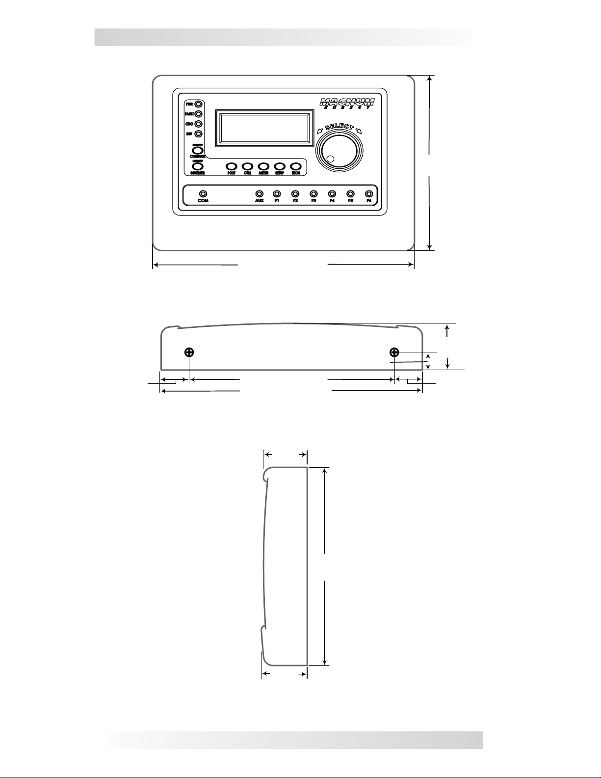
Figure 2-2, Router Dimensions ............................................................ 5
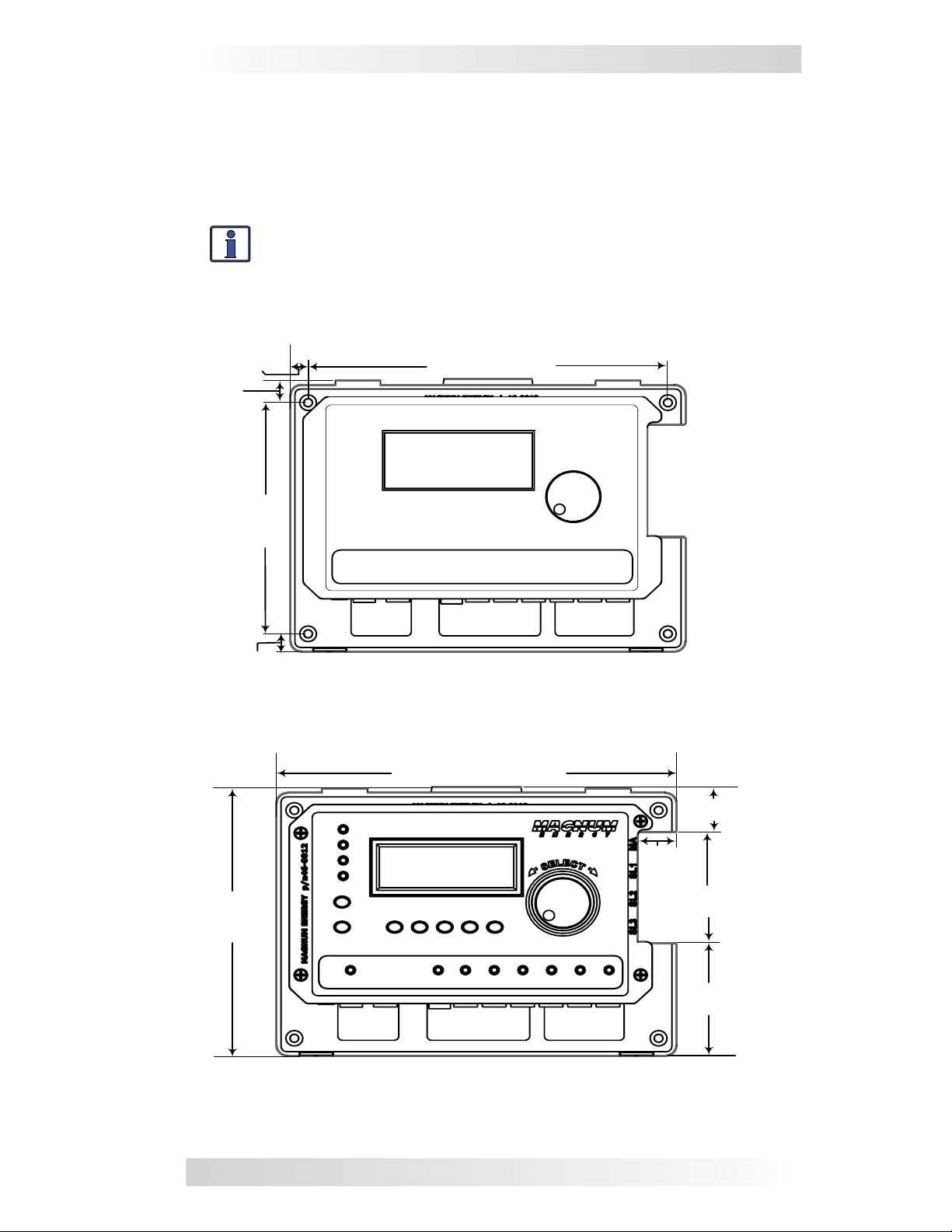
Figure 2-3, Router Mounting Holes ....................................................... 6
Figure 2-4, Internal Router Dimensions ................................................ 6
Figure 2-5, Connecting CAT 5 and Communication Cables to Inverters ...... 7
Figure 2-6, Connecting the CAT 5 Cables to the Router ........................... 7
Figure 2-7, Concealed Mounted Communication Cables ........................... 9
Figure 2-8, Surface Mounted Communication Cables ..............................9
Figure 2-9, Router Cover’s Cable Connection Cutouts ........................... 10
Figure 2-10, Wiring the Auxiliary Relay ............................................... 10
Figure 2-11, Installing the Router Cover ............................................. 11
Figure 2-12, Power-up Routine .......................................................... 11
Figure 3-1, Up and Down Arrows for Hidden Lines ................................ 12
Figure 3-2, PORT Button ................................................................... 13
Figure 3-3, CTRL (Control) Button ...................................................... 14
Figure 3-4, METER Button ................................................................. 18
Figure 3-5, SETUP Button ................................................................. 22
Figure 3-6, Aux Relay LED ................................................................ 25
Figure 3-7, TECH Button ................................................................... 39
Figure 3-8, Fault History ................................................................... 40
Figure 4-1 PORT/CTRL Button Menu Maps (page 1 of 9) ........................ 43
Figure 4-2 METER Button Menu Map (page 2 of 9) ............................... 44
Figure 4-3 SETUP Button Menu Map - Router (page 3 of 9).................... 45
Figure 4-4 SETUP Button Menu Map - Router (page 4 of 9).................... 46
Figure 4-5 SETUP Button Menu Map - Inverter (page 5 of 9).................. 47
Figure 4-6 SETUP Button Menu Map - Charger (page 6 of 9) .................. 48
Figure 4-7 SETUP Button Menu Map - Charger (page 7 of 9) .................. 49
Figure 4-8 SETUP (Accs)/TECH Menu Map (page 8 of 9) ........................ 50
Figure 4-9 TECH Button Menu Map (page 9 of 9) ................................. 51
Figure 5-1, ME-RTR Front Panel Controls and Indicators ........................ 52
Figure 5-1.1, SYSTEM Screen Status Messages .................................... 55
iii © 2010 Magnum Energy, Inc.
Page 5

List of Figures (cont.)
Figure 5-1.2, PORT Screen Status Messages ........................................ 55
Figure 5-2, OFF Mode...................................................................... .56
Figure 5-3, Searching Mode............................................................... 56
Figure 5-4, Inverting Mode............................................................... 56
Figure 5-5, Inverter Standby Mode .................................................... 57
Figure 5-6, Charging Mode ................................................................ 57
Figure 5-7, Bulk Charging Mode ......................................................... 57
Figure 5-8, Absorb Charging Mode ..................................................... 58
Figure 5-9, Float Charging Mode ........................................................ 58
Figure 5-10, Full Charge Mode ........................................................... 58
Figure 5-11, Charger Standby Mode ................................................... 59
Figure 5-12, Silent Mode .................................................................. 59
Figure 5-13, Force Float Mode ........................................................... 59
Figure 5-14, Equalizing Mode ............................................................ 60
Figure 5-15, VDC Connect Mode ........................................................ 61
Figure 5-16, Time Connect Mode ....................................................... 61
Figure 5-17, AC In - Disabled Mode .................................................... 61
Figure 5-18, Low Battery Fault .......................................................... 62
Figure 5-19, High Battery Fault ......................................................... 62
Figure 5-20, Overtemp Fault ............................................................. 63
Figure 5-21, AC Overload Fault .......................................................... 63
Figure 5-22, Hi Volts AC Fault ............................................................ 63
Figure 5-23, Dead Battery Charge Fault .............................................. 64
Figure 5-24, Overcurrent Fault .......................................................... 64
Figure 5-25, FET Overload Fault......................................................... 64
Figure 5-26, Breaker Tripped Fault ..................................................... 65
Figure 5-27, Unknown Fault xx .......................................................... 65
Figure 5-28, Transformer Overtemp Fault ............................................ 65
Figure 5-29, No Inverter Comm Fault ................................................. 66
Figure 5-30, StackClock Fault ............................................................ 66
Figure 5-31, Stack Mode Fault ........................................................... 66
Figure 5-32, StackPhase Fault ........................................................... 67
Figure 5-33, Internal Bridge Fault ...................................................... 67
Figure 5-34, Internal Charger Fault .................................................... 67
Figure 5-35, Internal NTC Fault ......................................................... 68
Figure 5-36, Internal Relay Fault ....................................................... 68
Figure 6-1, Performing an Inverter Reset ............................................ 72
List of Tables
Table 3-1, Battery Type to Charge Voltages ......................................... 31
Table 3-2, Battery Amp/Hrs Capacity to Suggested Absorption Time ....... 33
Table 5-1, LED Indicator Guide .......................................................... 69
Table 6-1, Router Control Troubleshooting Guide .................................. 70
© 2010 Magnum Energy, Inc. iv
Page 6
1.0 Overview
1.0 Overview
The ME-RTR, or “router” hereafter, has many of the same features as the
ME-ARC50 advanced remote with the added functionality required to parallel Magnum MS-PAE inverter/chargers. The router is designed to easily and
quickly connect the MS-PAE series inverter/charger in parallel without the
need to program each inverter. The router will accommodate up to four MSPAE inverter/chargers in parallel plus accessories.
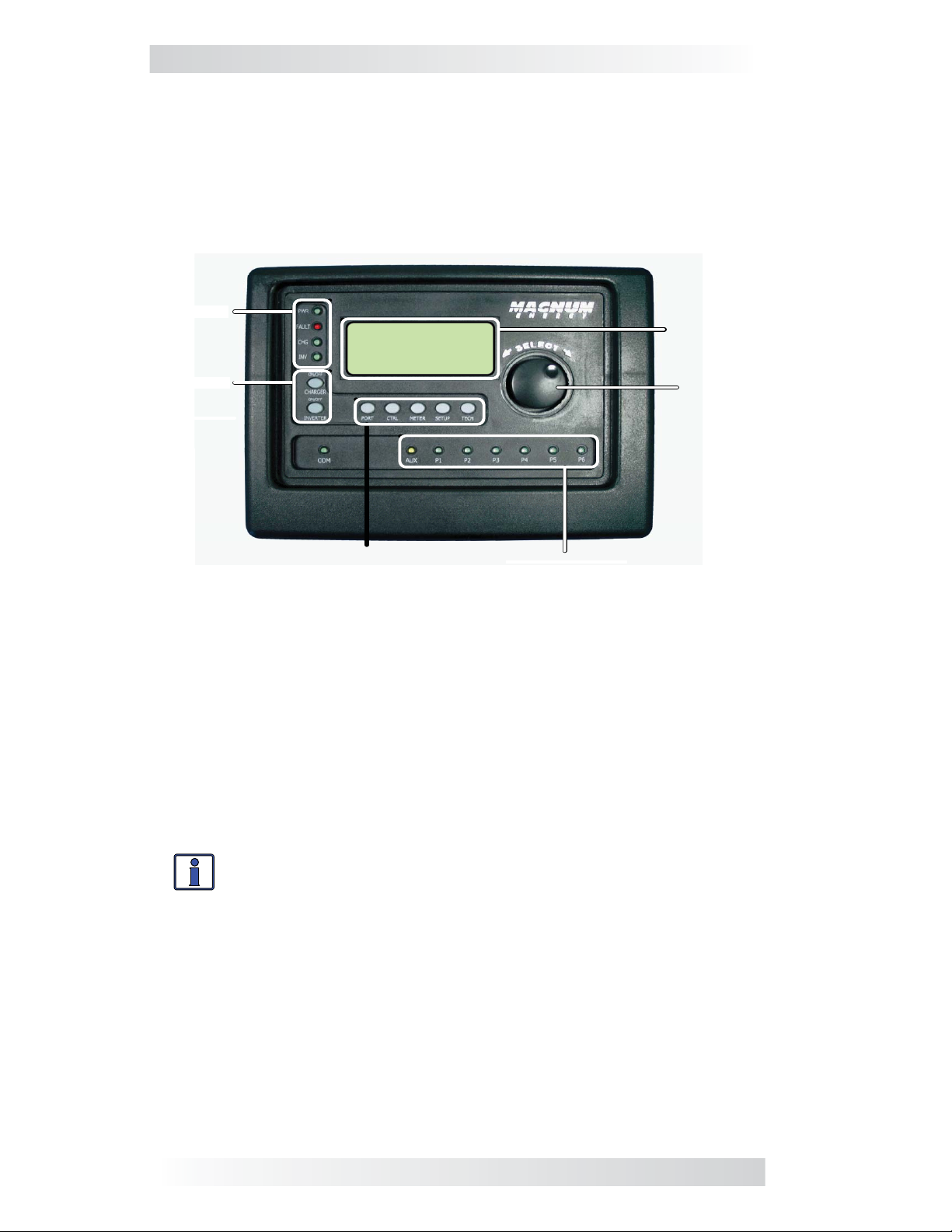
LED
LCD Display
Rotary
SELECT Knob
ON/OFF
Inverti ng
25 .6 VDC 20 Amps
Sys te m Home
PORT, CTRL, METER, SETUP,
TECH Buttons
LED Indicators
Figure 1-1, Front Panel Features
The ME-RTR is equipped with the following features:
LED Indicators - The at-a-glance LEDs provide the inverter/charger,
•
router, communication ports, and auxiliary relay statuses in a
straightforward way.
LCD Display - The LCD display is a 20 x 4 line (80 characters total)
•
alphanumeric display used for setting up the inverter/charger operation,
as well as viewing current status or fault messages.
ON/OFF Pushbuttons (x2) - Allows all the inverters or chargers to be
•
quickly enabled or disabled.
Info: The router’s ON/OFF INVERTER and ON/OFF CHARGER
buttons function normally when a ME-ARC is connected
through a router in a parallel system.
PORT Button - This button scrolls through the six communication and
•
accessory ports and displays information.
CTRL Button - This button is used to select inverter, charger, and AGS
•
functions previously set up using the SETUP button.
METER Button - This button is used to access the ‘read only’ meters for
•
DC, AC, AGS, and BMK.
SETUP Button - This button is used to access the setup menus for the
•
inverter, charger, AGS, and BMK. The SETUP button may be password
protected to keep unauthorized users from accessing the SETUP
menus.
1 © 2010 Magnum Energy, Inc.
Page 7
1.0 Overview
TECH Button - This button is used to access technical information, fault
•
history, and to set a password for the SETUP button.
Rotary Knob/SELECT Button - The rotary encoder knob is similar to
•
a dash radio knob and is used to quickly scroll through Ports 1-6, or to
select various menu items and settings. Pressing this rotary knob allows
you to select a menu item or to save a setting, once it is displayed on
the LCD screen.
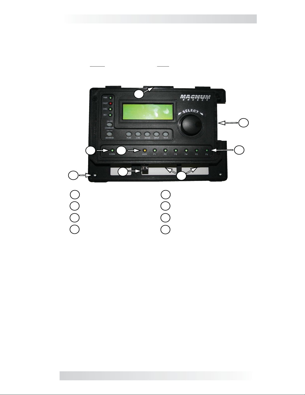
A
B
ED
F
Mounting tabs for top cover
A
Parallel CAT 5 jacks (x4)
B
C
LEDs for communication (P1-P6)
LED for Comm (not functional,
D
for future use)
G
Figure 1-2, Router Connections Overview
H
E
LED for Aux Relay operation
F
Mounting screw holes (x4)
Aux Relay 2-wire terminal
G
w/ removable plug
H
Communication ports (P1-P6)
C
© 2010 Magnum Energy, Inc. 2
Page 8

2.0 Installation
2.0 Installation
Review this entire section before proceeding with the installation of your router.
The more thorough you plan in the beginning, the better your router/parallel
system needs will be met.
WARNING: Installations should be performed by qualifi ed
personnel, such as a licensed or certifi ed electrician. It is the
installer’s responsibility to determine which safety codes apply
and to ensure that all applicable installation requirements are
followed. Applicable installation codes vary depending on the
specifi c location and application.
Info: Review the Important Product Safety Information section
on the front inside cover page before any installation.
2.1 Installation Guidelines
•
Before connecting any wires determine the router’s cable route throughout
the home or vehicle/boat, both to and from the inverter.
•
Always check for existing electrical, plumbing, or other areas of potential
damage BEFORE drilling or cutting into walls to mount the router.
Make sure all wires have a smooth bend radius and do not become
•
kinked.
If installing this router in a boat, RV, or truck ensure the conductors
•
passing through walls, bulkheads, or other structural members are
protected. This minimizes insulation damage such as chafi ng, which can
be caused by vibration or constant rubbing.
2.2 Tools Required
Installing the router is a simple process and requires the following tools:
• Phillips screwdriver • Level • Drill
• Cut-out tool (knife/saw) • Pencil • Drill bit (7/64”)
2.3 Installation Overview
The ME-RTR is required in order to parallel stack the MS-PAE Series inverter/
charger. Each inverter/charger must be connected directly to the router using
the supplied CAT 5 and RJ11 communication cables. DO NOT substitute for
the supplied cables. The router comes with four 6 ft. CAT 5 cables and four 6
ft. RJ11 communication cables rated at 300 VAC – which is required to meet
NEC/CEC codes when installing the router in a Magnum Panel system.
Each paralleled inverter/charger requires a CAT 5 high speed communication
cable to be connected to the router’s parallel stacking ports marked MA (Master), SL1 (Slave 1), SL2 (Slave 2), and SL3 (Slave 3). One inverter/charger
will always be designated the Master, and subsequently any other connected
inverter/chargers will be designated as Slaves. You can stack up to four MSPAE Series inverter/chargers using one router.
The router must be located close to the inverter/chargers (within fi ve feet) and
acts as the system control panel. If a remote monitoring location is required,
a ME-RC50 or ME-ARC50 may be connected to one of the communication
ports (P1-P6) on the router, and will act as a remote on/off switch and assist
in monitoring the system.
3 © 2010 Magnum Energy, Inc.
Page 9
2.0 Installation
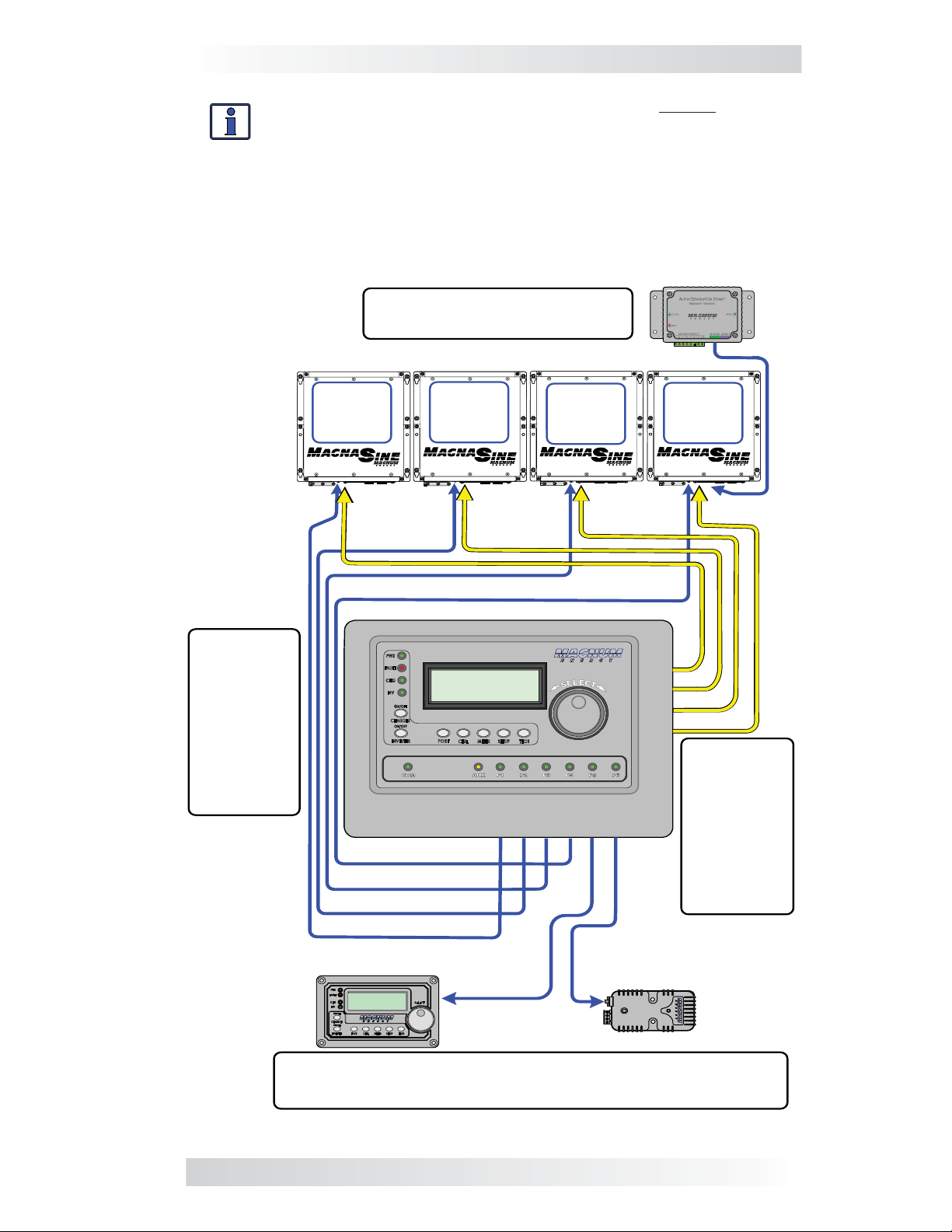
Info: It is recommended that you set up the master inverter/
charger as the fi rst unit on the left so that the CAT 5 and
communication cables are connected to the inverter/chargers
in order from left to right – MA (Master), SL1, SL2, and SL3.
This confi guration makes it easy to identify the master and slave
units without having to trace the wires from the router to each
inverter/charger.
ME - AGS - N
Cable from ME - AGS - N
to Network Port (green)
Cables
(x4) from
router to
each
inverter’s
Remote
Port
(blue)
#1
MS-PAE
I
NVERTER
(M
ASTER
#2
MS-PAE
I
NVERTER
(S
LAVE
)
1)
#3
MS-PAE
I
NVERTER
(S
LAVE
2)
MA
SL1
SL2
SL3
#4
MS-PAE
I
NVERTER
(S
LAVE
3)
Cables
(x4) from
router to
P1 P2 P3 P4 P5 P6
each
inverter’s
Stack Port
(red)
ME - ARC
ME - BMK
Cables from router to ME - BMK/ME - BMK - NS and
ME - ARC, or to ME - AGS - N
Figure 2-1, System Overview
© 2010 Magnum Energy, Inc. 4
Page 10
2.0 Installation
15/16" (22.7 cm)
8
FRONT VIEW
6
5/8"
(16. 8 cm )
15/16"
(2.4 cm)
7
1/16" (17.9 cm)
8
15/16" (22.7 cm)
BOTTOM VIEW
(3.8 cm)
1 ½
”
6
5/8"
(16. 8 c m)
5/8"
(1.6 cm)
1
9/16"
(4 cm)
15/16"
(0.9 cm)
1
9/16
"
(4 cm)
RIGH T SIDE
Figure 2-2, Router Dimensions
5 © 2010 Magnum Energy, Inc.
Page 11
2.0 Installation
2.4 Mounting the Router
To mount the router:
1.
Select an appropriate location to install the router.
2.
Mount the router base to the wall using the 4 screws provided. See
Figure 2-3.
Info: If the router is being installed on a Magnum Panel en-
closure (MP), it can be attached to either the left or right-hand
side using the bracket (ME-RTR-B) provided. Refer to the MP
manual (PN: 64-0028) for information on mounting the router
on a MP panel.
3/8"
(0.9 cm)
½
"
(1.3 cm)
8"
(20.3 cm)
5
½
(14 cm )
7/16"
(1.1 cm)
6 ½
(16. 5 c m)
"
"
Figure 2-3, Router Mounting Holes
8
13/16" (22.4 cm)
1
1/16"
(2.7 cm)
7/8"
(2.2cm)
2
11/16"
(6.8 cm)
2 ¾
"
(7 cm)
FRONT - BEZEL
REMOVED
Figure 2-4, Internal Router Dimensions
© 2010 Magnum Energy, Inc. 6
Page 12
2.0 Installation
2.5 Connecting the CAT 5 Parallel Stacking Cables
The router comes with four 6 ft. CAT 5 cables for parallel stacking. These
cables must be used when installing the router. They are like standard CAT 5
cables, but are rated for 300 VAC to allow their use with the MS-PAE inverters,
and they meet the electrical safety code requirements.
To connect the CAT 5 parallel stacking cables:
Connect a CAT 5 cable to the Stack Port on every inverter installed in
1.
parallel (see Figure 2-5).
Route the inverter-connected CAT 5 cables from each inverter/charger
2.
to your router. Depending on your particular setup, the cables may need
to be routed through walls or the MP Panel enclosure system.
Connect each CAT 5 cable to its respective CAT 5 port on the router (MA,
3.
SL1, SL2, and SL3 ports for the appropriate number of inverters installed
in parallel). See Figure 2-6.
Info: At least one CAT 5 cable must be plugged into the router’s
MA port in order for the router to operate any inverters.
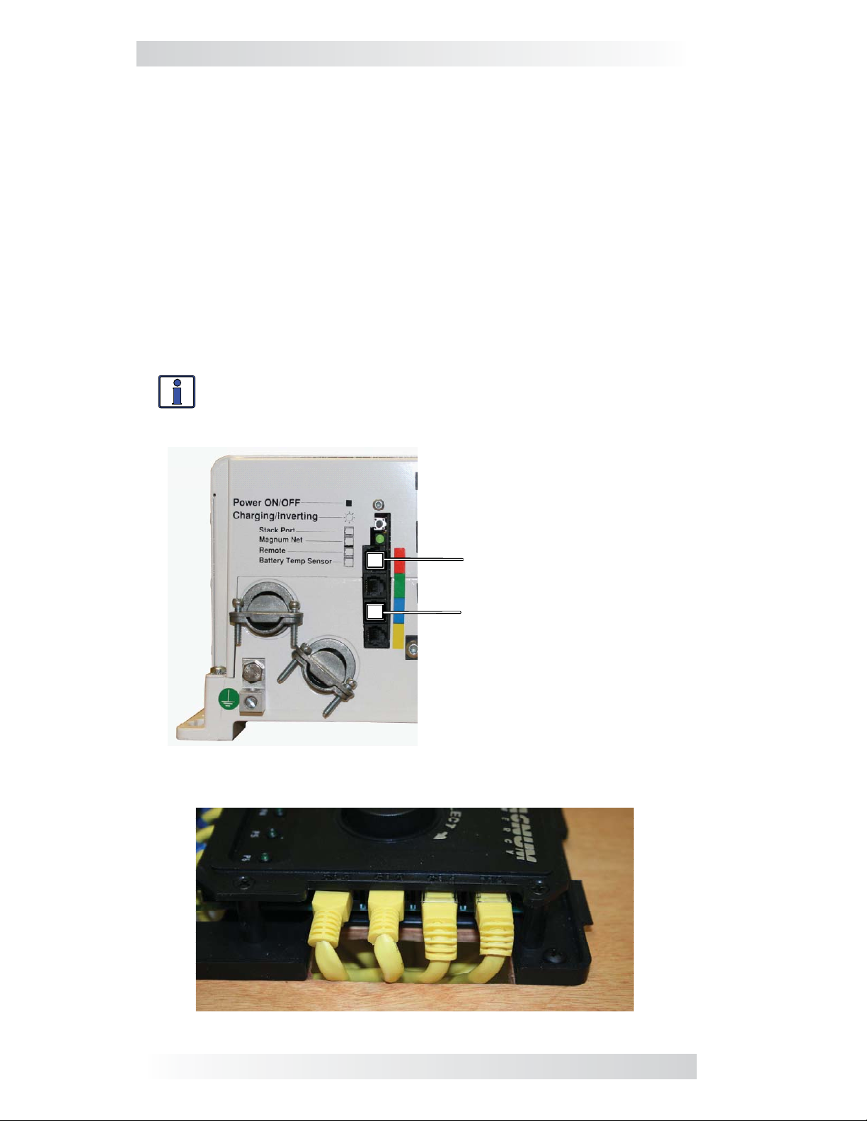
Connect the CAT 5 cable to the
top port marked “Stack Port .”
Connect the communication cable
to the port marked “Remote.”
Figure 2-5, Connecting CAT 5 and Communication Cables to the
Inverters
Figure 2-6, Connecting the CAT 5 Cables to the Router
7 © 2010 Magnum Energy, Inc.
Page 13

2.0 Installation
2.6 Connecting the Communication Cables
To connect the communication cables:
Connect a communication cable to the Remote port on every inverter
1.
installed in parallel (see Figure 2-5), using the supplied remote cables.
Route the inverter-connected communication cables from each inverter/
2.
charger to your router. Follow the same route you used for the CAT 5
cables.
Connect each communication cable to its respective communication port
3.
on the router. (P1-P6 for the appropriate number of inverters installed in
parallel.) Refer to Section 2.6.1 and Figures 2-7 through 2-9.
Connect any accessories to the remaining open communication ports
4.
on the router.
Info: It is recommended that the Master inverter be connected
to remote communication Port 1, Slave 1 to remote communication Port 2 etc., in order to more easily keep track of which
inverter is displayed on each port.
Info: It is recommended that all accessories be connected
directly to the router using any available communication ports
(P1-P6). Except for remotes (i.e., ME-RC or ME-ARC), if there
are additional accessories to connect, but all the router’s communication ports are being used, the additional accessories may
be connected to the Network ports on the stacked inverter/chargers. Any accessory connected directly to the Network port on
an inverter/charger will display as an accessory on the router
port to which the inverter/charger is connected.
Example: A ME-AGS-N connected to the Network port on the
master inverter (P1) will display as P1Acc on the router.
Info: Multiple accessories of the same type may be connected
to the system, but there are some limitations to the number
of accessories. You may connect a maximum of one ME-RC or
ME-ARC remote, two ME-AGS-N modules, and any number of
ME-BMK/ME-BMK-NS accessories.
Info: The ME-ARC or ME-RC remote must be connected directly
to the router and programmed to indicate which port the remote
is monitoring. It is recommended that the ME-RC or ME-ARC
is set to monitor “System” in most installations. The ME-RC
or ME-ARC must not be directly connected to the Remote or
Network ports on the MS -PAE inverter when the router is also
connected.
Info: When used in conjunction with a router, a ME-RC or ME-
ARC has limited functions. The remote control monitors the port
it is designated to display, turns all parallel inverter/chargers
on/off, and displays METER and TECH information. The ME-ARC
does not control the inverter/chargers via the CTRL button.
© 2010 Magnum Energy, Inc. 8
Page 14
2.0 Installation
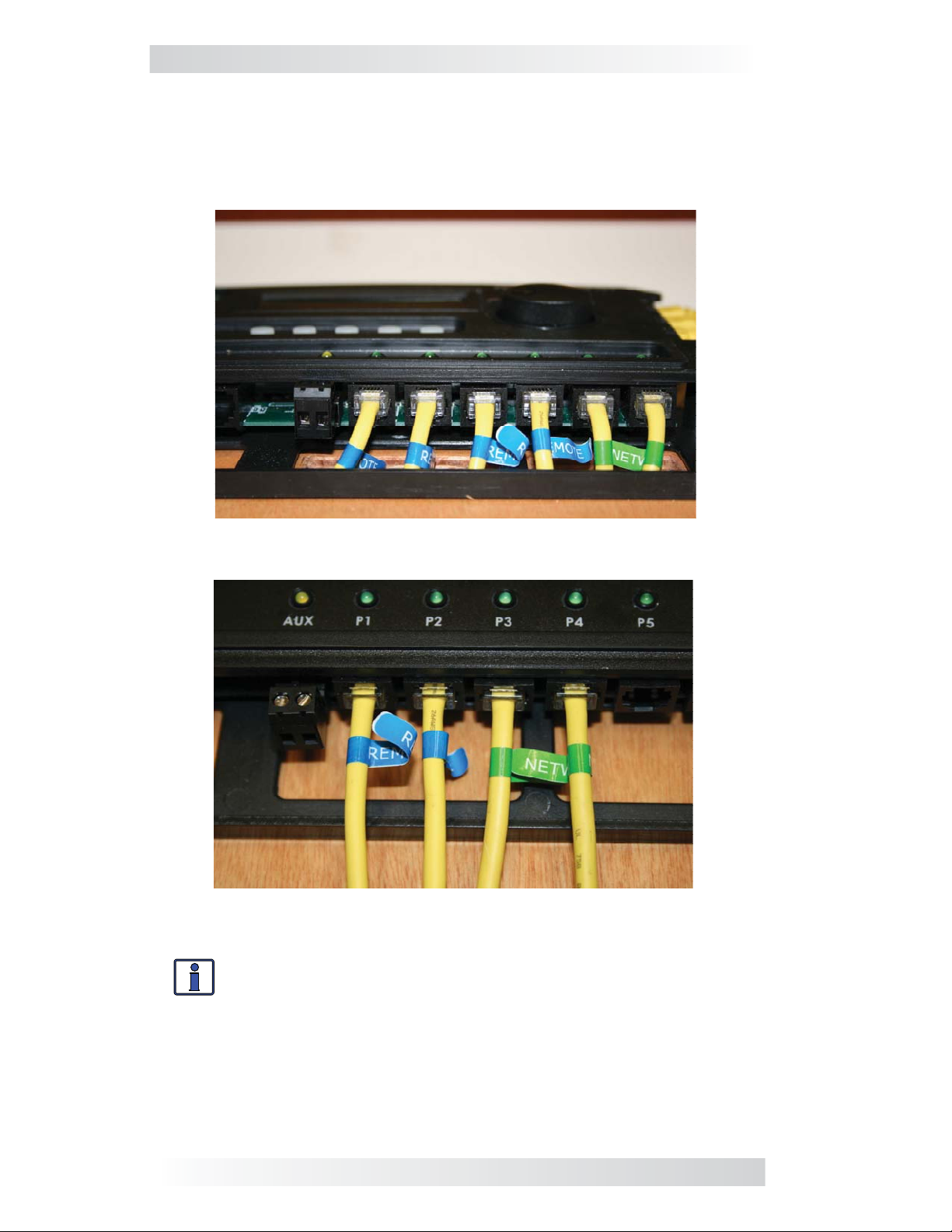
2.6.1 Optional Cable Connection Routes
You can either surface mount or conceal the cable connections to the router.
The cables can be fl ush mounted through an opening in a wall (Figure 2-7);
or, if there is insuffi cient room behind the wall or no desire to cut into the
wall, the cables can be surface mounted (Figures 2-8).
Figure 2-7, Concealed Mounted Communication Cables
Figure 2-8, Surface Mounted Communication Cables
Info: The CAT 5 and communication cables may be installed
on the mounting surface or through the wall. If the cables are
installed on the surface, the router cover has cutout sections to
accommodate the cables (see Figure 2-9). These cutout sections
are made thinner to allow them to be easily broken or cut. Only
remove those cutout sections needed for the number of cable
connections you are installing.
9 © 2010 Magnum Energy, Inc.
Page 15
2.0 Installation
BOTTOM VI EW – ROUTER COVER
Communication cable cutouts (x9)
RIGHT SIDE VIE W – ROUTER COVER
CAT 5 cable cutouts (x4)
Figure 2-9, Router Cover’s Cable Connection Cutouts
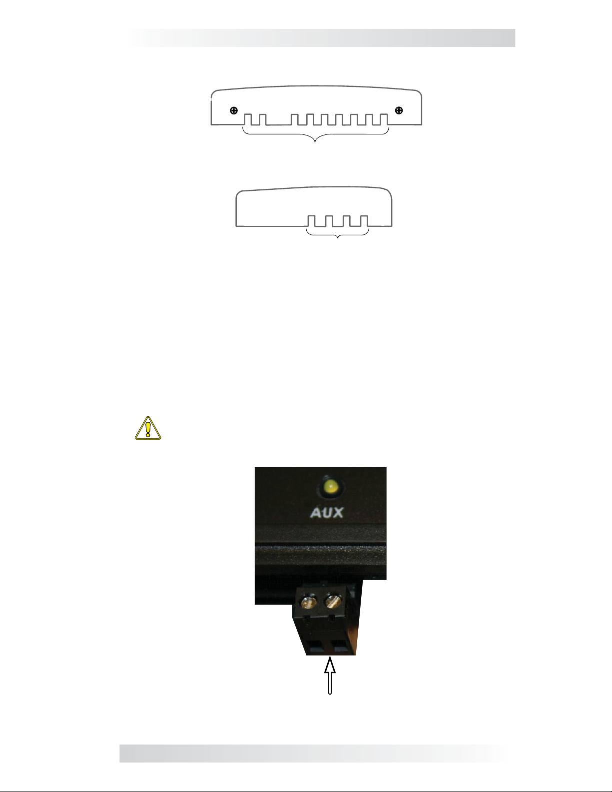
2.7 Wiring the Auxiliary Relay
The Aux Relay is a 2-wire dry contact relay that is either normally open or
closed. The Aux Relay may be wired to any device requiring a contact closure that draws no more than 0.1 amp of current. The Aux Relay is a voltage
controlled relay and may be programmed to open or close on VDC, with an
adjustable delay.
CAUTION: When wiring the Aux Relay, use an inline 0.5 amp
fuse to protect the relay. Damage to this relay is not covered
by warranty.
2-wire dry contact terminal
Figure 2-10, Wiring the Auxiliary Relay
© 2010 Magnum Energy, Inc. 10
Page 16
2.0 Installation
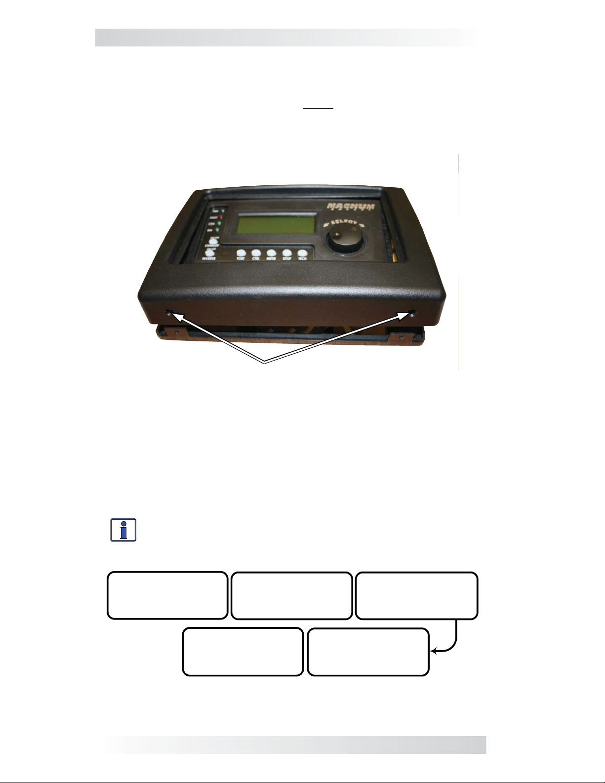
2.8 Installing the Router Cover
Once all the wiring is completed, you are ready to install the router cover.
Tip the top of the cover down and hook it over the router top (protruding
horizontal tabs on inside top of cover go under corresponding mounting tabs
at top of router), and then drop the cover down (cover the router’s bottom
vertical tabs). Install the two fl athead Phillips screws into the bottom tabs to
hold the router cover in place.
Install with two flathead Phillips
mounting screws
Figure 2-11, Installing the Router Cover
2.9 Power-up Routine
When the router is first connected to an inverter, a power-up routine is
initialized. During the power-up routine, the LCD displays “MAGNUM ENERGY
ROUTER Ver x.x”. The next three screens prompt you to set HOURS, MINUTES,
and AM/PM. Once the clock has been set, the router displays the SYSTEM
HOME screen.
Info: Pressing and holding down the METER button for three
seconds takes you back to the System Home screen from any
menu.
Set Clock
12:15 am
ALL EDIT RTR Setup
12:00 pm
MAGNUM ENERGY
ROUTER
Ver 2.1
Set Clock
12:00 am
ALL edit RTR Setup
Set Clock
MS4024PAE
System Home
Figure 2-12, Power-up Routine
11 © 2010 Magnum Energy, Inc.
ALL EDIT RTR Setup
Page 17
3.0 Setup
3.0 Setup
When a router is connected to a Magnum inverter/charger, the settings in the
router determine the inverter/charger’s operating parameters. The router’s
default settings are adequate for most installations; however, you have the
option to change some of the operating parameters. This section shows you
how to navigate the router and gives you an understanding of the function of
each adjustable setting. See Figures 4-1 thru 4-9 for complete maps of the
router’s menu items and adjustable settings.
*** IMPORTANT ***
All settings/setup menus in the router are compatible with MS-PAE Series
inverter/chargers. If you are using the router with another inverter/charger
(other than the MS-PAE Series), some features and setup menus may not
be compatible with your inverter and will not function. Contact Magnum
Energy to determine if a particular feature/setup menu provided in the
router is compatible with your inverter.
3.1 Navigating the Router
Familiarize yourself with the controls on the front panel which are used to fi nd,
adjust, and save the desired settings (refer to Figure 1-1). They are:
• LCD Display - The 4-line LCD display shows status and info for the inverter/
charger and any attached accessories. All setup menus and faults also appear
on the LCD display.
Info: The LCD display returns to the System Home screen to show
system status after 5 minutes if no buttons have been pressed.
Info: When the “←” (left facing arrow) symbol is shown on the
screen it indicates that the displayed setting has been selected
and will be used.
• Menu Pushbuttons (x5) - These buttons allow simple access to menu
items that can help with confi guring, monitoring, and troubleshooting your
inverter/charger system.
• Rotary SELECT Knob - This rotary knob allows you to quickly scroll through
and select various menu items and settings. Pressing the knob selects the
menu item to change, or saves the current selection. Refresh the LCD display
by holding the rotary knob down for seven seconds.
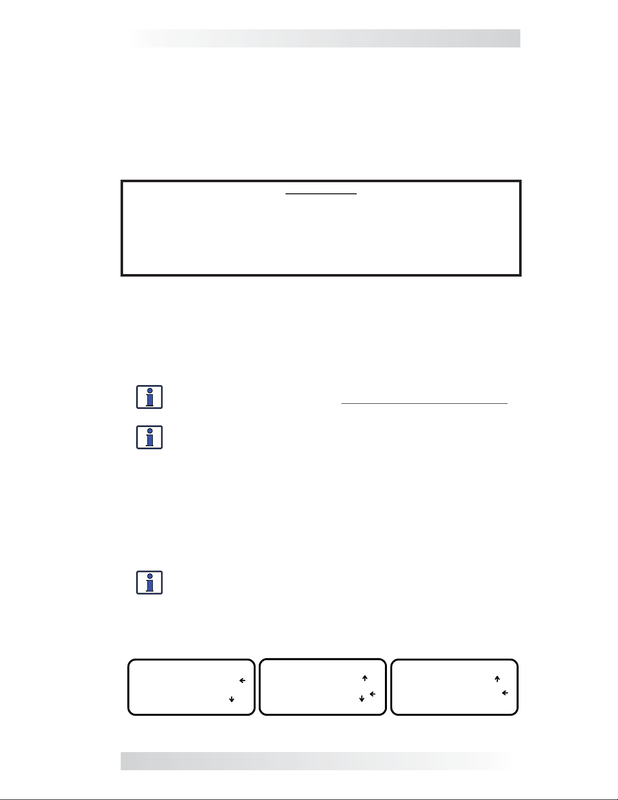
Info: The LCD screen features a 4-line display. If there are
more choices than will fi t on the screen, up and down arrows
are present to guide you in accessing those choices. An up arrow
indicates you must rotate the SELECT knob counterclockwise to
display the next line. A down arrow requires a clockwise rotation.
If both an up and down arrow display, rotate the SELECT knob
clockwise or counterclockwise to display all hidden lines.
Set AC In Control
Auto Connect
VDC Connect
EDIT Control
Figure 3-1, Up and Down Arrows for Hidden Lines
© 2010 Magnum Energy, Inc. 12
Set AC In Control
VDC Connect
Time Connect
EDIT Control
Set AC In Control
Time Connect
AC In – Disabled
EDIT Control
Page 18
3.0 Setup
3.2 Router Pushbuttons and Menu Items
The fi ve pushbuttons (PORT, CTRL, METER, SETUP, and TECH) located beneath
the LCD screen allow the inverter/charger system to be confi gured to your
specifi c preferences. These pushbuttons also allow you to access menu items
that can help with monitoring and troubleshooting your system.
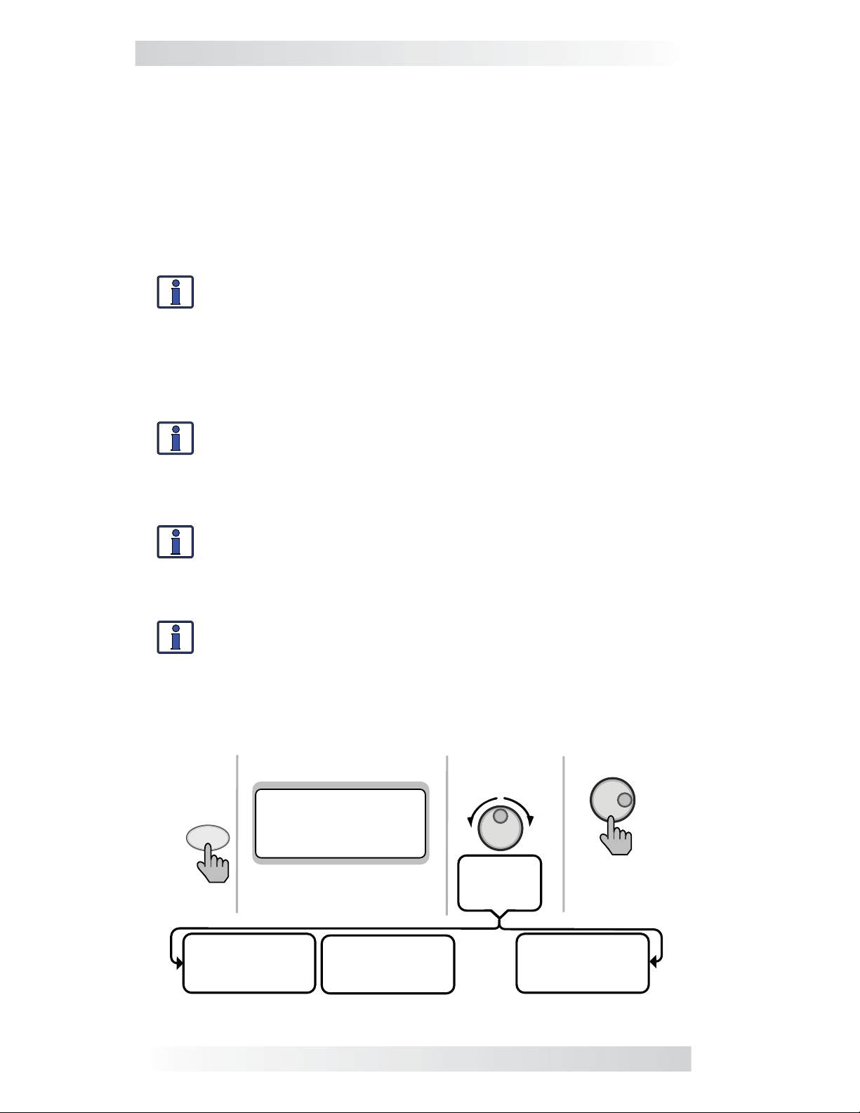
3.2.1 PORT Button
The PORT button scrolls between the six communication ports on the bottom
of the router. Each parallel inverter/charger must be connected to a communication port in order to be programmed and to display status info.
Info: You must be on a Home screen menu (“Home” appears
in bottom right corner of router’s LCD display) in order for the
PORT button to scroll through all the active ports. If you are not
on a Home screen, pressing the PORT button will only display
devices that are related to the screen you are currently viewing
(only true for METER, SETUP, and TECH button menus, PORT
button does not work from CTRL button menus).
Info: Pressing and holding down the METER button for 3-seconds
takes you back to the System Home screen from any menu.
Any remaining open ports may be used to connect Magnum accessories such
as an ME-AGS-N, ME-BMK/ME-BMK-NS, and an ME-RC or ME-ARC remote.
Info: You can connect a maximum of four inverter/chargers
to a router. If the maximum number of inverter/chargers are
connected, two open ports remain. If more ports are needed
for accessories, the Network port on each inverter/charger may
also be used for accessories.
Info: When an accessory is plugged into a communication port
on the router, the PORT button displays the accessory as the
corresponding port (i.e., Port 5 would show “ME-AGS-N”). If an
accessory is plugged into the Network port on one of the parallel
inverter/chargers, the PORT button will display the accessory
as “P#Acc” (i.e., a ME-AGS-N plugged into a parallel inverter/
charger that is plugged into Port 1 would display as “P1Acc”).
Top line shows status
OR rotate to
next port
MS4024PAE
Inverting
PORT
Press
25.6 VDC 20ADC
System INV Home
Bottom line shows current
port. Press PORT button to
access next port.
Rotate to
desired
selection:
Press to edit
setting
MS4024PAE
Inverting
25.6 VDC 10 ADC
P1 INV Home
Auto Gen Start
Ready 0.0 Hrs
25.6 VDC 70F
P1Acc AGS Home
…......
MS4024PAE
Inverting
25.6 VDC 10 ADC
P3 INV Home
Figure 3-2, PORT Button
13 © 2010 Magnum Energy, Inc.
Page 19
3.0 Setup
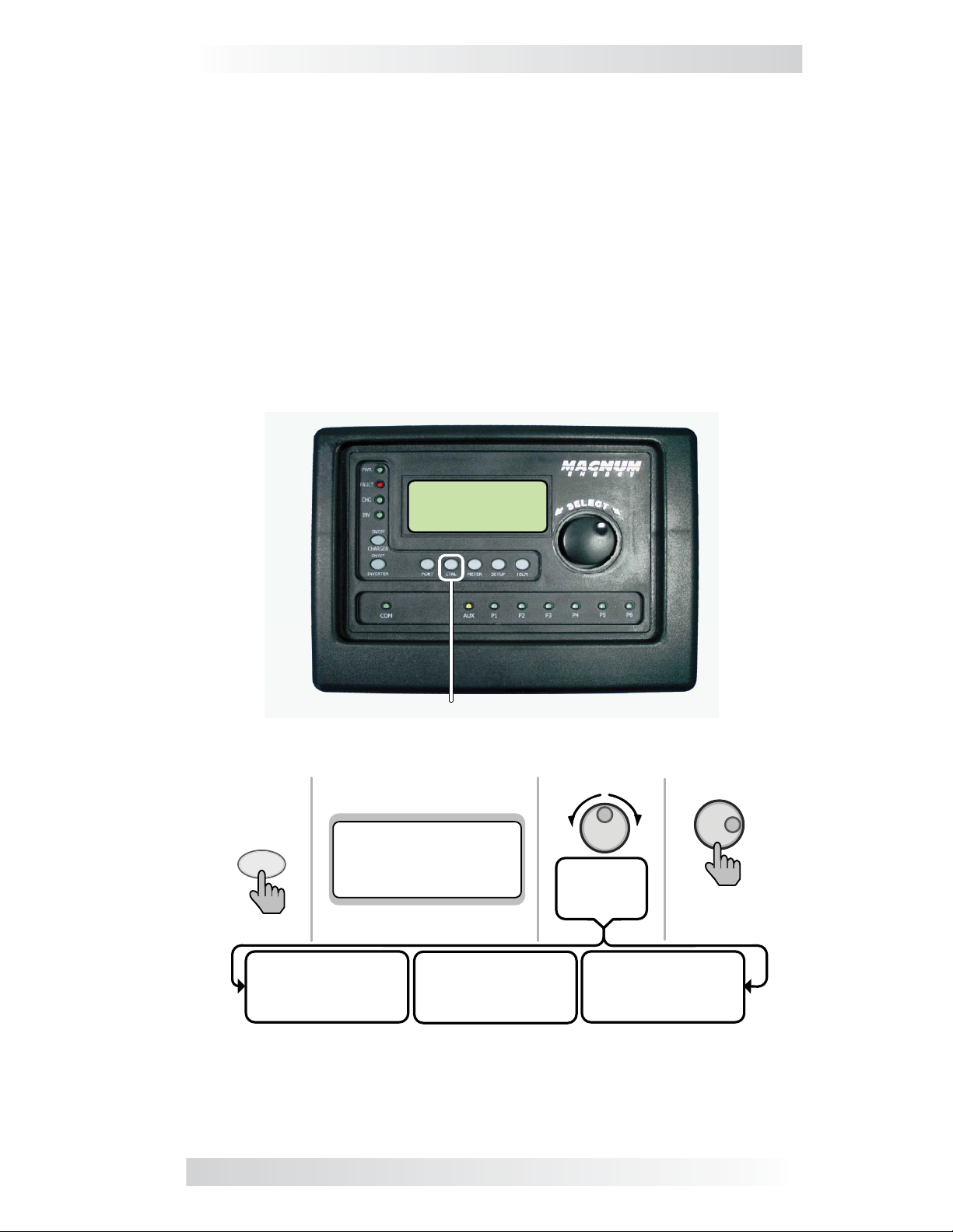
3.2.2 CTRL (Control) Button
The CTRL button contains the menus for 01 AC In Control, 02 CHG Control,
and 03 Gen Control (an AGS must be connected in order for the Gen Control
menu to display). The CTRL button gives you quick control of the main functions
of the inverter/charger without having to access the SETUP menus in order
to change the operation of the inverter/charger or the generator. Once the
settings have been programmed in the SETUP menus, the features can then
be enabled using the CTRL button.
Example: The SETUP menu’s 02C AC In - Time setting is used to set what
time of day (e.g., 12AM to 8AM) you want the inverter to connect to the
incoming AC. Once this time is set, use the CTRL button to access the
AC In Control menu item and select Time Connect. When Time Connect
is selected, the inverter/charger will only connect to AC when the time
is between 12AM and 8AM.
01 A C In Control
Auto Connec t
View Contr ol
Top line shows menu
01 AC In Control
CTRL
Auto Connect
View Control
Press
01 AC In Control
Auto Connect
View Control
Bottom line shows view
Figure 3-3, CTRL (Control) Button
CTRL
Button
02 CHG Control
Multi-Stage
View Control
Rotate to
desired
selection:
03 Gen Control
OFF
View Control
Press to
edit setting
© 2010 Magnum Energy, Inc. 14
Page 20

3.0 Setup
01 AC In Control
The 01 AC In Control menu has four different conditions in which the
inverter/charger will connect to incoming AC power. Only one condition may
be selected at any one time – multiple conditions can be enabled, but only
one can be active.
Info: Before the inverter allows the AC input to connect to the
AC source (grid or gen), the incoming AC must be qualified by
the inverter/charger (voltage is below the high AC input require-
ments, above the VAC Dropout setting, and between 50 Hz to
70 Hz for domestic models – 40-60 Hz for export models).
Info: The top status line of the LCD display alternates the
inverter/charger status with a secondary AC IN status when
AC is present, but is not connecting as a result of a selection
made in the SETUP menu.
•
Auto Connect: Automatically connects to incoming AC power.
•
VDC Connect: Connects to incoming AC when the DC battery voltage
is below the Set Connect Volts setting in the 02D AC IN VDC menu.
Disconnects from incoming AC when the DC battery voltage is above the
Set Disconnect Volts setting, also in the 02D AC IN VDC menu.
Info: See SETUP menu 02D on page 28 for a complete
explanation of the Set Connect Volts setting.
•
Time Connect: Connects to incoming AC when the time of day is between
the Set Connect Time and Set Disconnect Time settings per the 02C AC
In - Time menu.
Info: See SETUP menu 02C on page 27 for a complete
explanation of the Set Connect Hour/Minute/AM-PM setting.
AC In - Disabled: Disconnects incoming AC when selected. This setting
•
will prevent incoming AC from connecting to the inverter/charger.
Example: AC is present, but Time Connect has been selected from the
01 AC In Control menu, and the current time of day is 6PM. The 02C AC
In-Time menu’s current setting is 2AM - 8AM. The current time of 6PM is
outside the connect time, so the inverter/charger will not connect to the
incoming AC until after 2AM. The primary status will display “Inverting”
and the secondary status will display “Time Connect” to let you know the
reason that incoming AC has not connected.
15 © 2010 Magnum Energy, Inc.
Page 21
3.0 Setup
02 CHG (Charge) Control
02 CHG Control allows you to set the Charger mode to Multi-Stage, Force
Float, or to Restart Bulk. Most of the time the charger should be left in the
Multi-Stage setting, but to override this setting use the CTRL button and the
CHG Control menu. The charger can be forced into the Float mode or you
can start the Bulk mode using the Force Float or Restart Bulk settings from
the CTRL button’s 02 CHG Control menu item.
•
Multi-Stage: This charge profi le starts in Bulk mode (maximum cur-
rent). It transitions to the Absorption stage (constant voltage). When
the Absorption voltage is reached (as determined by the SETUP menu’s
03E Absorb Done setting), it fi nally transitions to the fi nal charge stage
as selected in the SETUP menu’s 03G Final Charge Stage menu item.
Info: Multi-Stage must be selected in order to use the fi nal
charge stage selected in the 03G Final Charge Stage menu.
Force Float: This charge profi le forces the charger to stay in the Float
•
mode as long as AC is present and the charger is active. Force Float is
most often used when another source of charging such as PV, wind, or
hydro is available to keep the batteries at or above the fl oat voltage. If
AC is disconnected and then reconnected the charger will go directly to
the Float mode, and will not initiate a Bulk or Absorption charge cycle.
CAUTION: Using the Force Float setting may not fully charge the
batteries. Most batteries require a Bulk and Absorption charge
cycle in order to fully recombine the electrolyte in the batteries
and bring the specifi c gravity to the proper level. Be sure to check
with your battery manufacturer before using this setting.
Info: If Silent is selected from the 03G Final Charge Stage menu,
you can override this selection with Force Float to temporarily
fl oat the batteries.
Restart Bulk: This selection restarts the Bulk cycle from any stage in
•
the charge cycle. The Restart Bulk setting is useful when a full Multi-
Stage charge cycle does not bring the specifi c gravity of the batteries
to the proper level.
Info: The Restart Bulk setting automatically defaults back to
the Multi-Stage setting once the inverter/charger status displays
“Bulk Charging”.
Info: If you have to continually restart the Bulk cycle in order
to bring the batteries to full charge, check the settings from the
SETUP button’s 03 Charger Setup menu items to make sure the
batteries are fully charged at the end of a regular Multi-Stage
charge cycle. Check with your battery manufacturer for proper
battery charger settings.
CAUTION: Frequently restarting the Bulk cycle may result in
overcharging of the batteries.
© 2010 Magnum Energy, Inc. 16
Page 22

3.0 Setup
03 Gen Control
03 Gen Control is used for controlling a standby generator that is connected
to the system and using the optional ME-AGS-N module. Once the ME-AGS-N
is installed in the system, the generator can be manually started and stopped,
or set to start and stop automatically from the Gen Control menu.
Info: An ME-ARC must be directly connected to one of the
router’s communication ports in order to be used (in a remote
location) to control a generator that is connected to an MEAGS-N.
Info: When the ME-ARC is connected directly to the router, the
CTRL button function of the ME-ARC is defeated. However, the
ME-ARC does contain the Gen Control selection in its FAVS menu.
This allows the generator to be controlled via the ME-ARC through
the FAVS menu, but not through the CTRL menu.
Info: The ME-AGS-N must be installed in order for the 03 Gen
Control menu to control a standby generator. Refer to the ME-
AGS-N manual (PN: 64-0039) for more information on controlling
standby generators.
OFF: The OFF selection will stop the generator by sending a ‘stop’
•
command from the ME-AGS-N control module (can be running from
either a manual start or an autostart command). When the OFF setting
is selected, the generator will not start automatically.
Info: If DC power is lost to the router, this menu resets to the
default OFF position for safety.
•
ON: The ON selection will start the generator by sending a ‘start’ com-
mand from the ME-AGS-N control module. Once the generator is start-
ed, it may be stopped by selecting OFF from the 03 Gen Control menu,
which sends a stop command from the ME-AGS-N.
Info: You can manually start and automatically stop a connected
generator by selecting ON from the Gen Control menu, and then
change the selection to AUTO. When the AUTO setting is selected
after the generator has been manually started, it will use the
stop setting in either the SETUP button’s Set Stop Gen Volts or
Set Max Gen Run Time menu items, whichever occurs fi rst.
Info: The ON selection uses warm-up time. The OFF selection
stops immediately and does not use the cool-down time.
AUTO: This selection uses the settings in the 04 AGS Setup menus to
•
automatically start and stop the generator based on battery voltage,
time of day, AC load on the inverter, high temperature, or battery state
of charge (requires a ME-BMK/ME-BMK-NS accessory). Refer to the 04
AGS Setup section on page 37 to set the start and stop parameters for
the generator.
17 © 2010 Magnum Energy, Inc.
Page 23
3.0 Setup
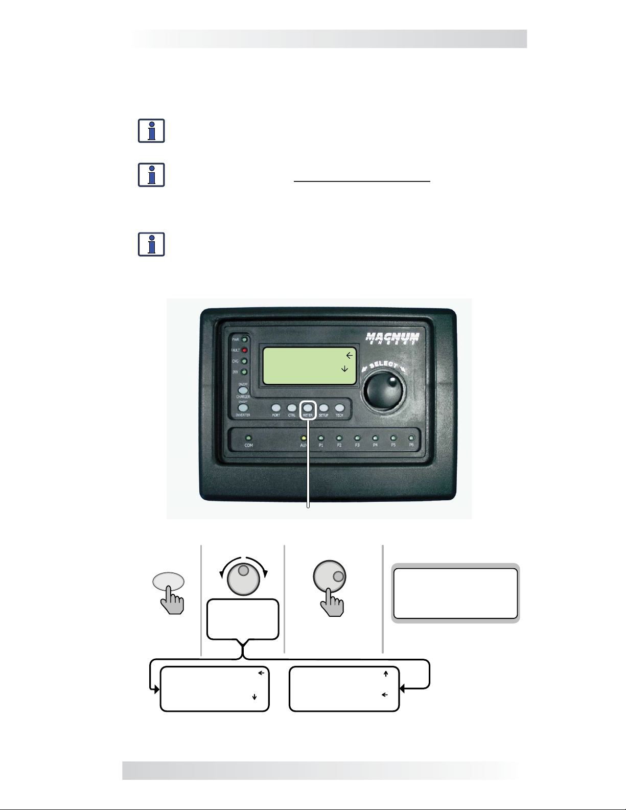
3.2.3 METER Button
The METER button gives you access to different meters which help determine
the status of the inverter/charger and battery system.
Info: Some METER functions may not be accessible with older
inverter software. If some meters do not function, check for
current inverter software.
Info: Most displays automatically return to the System Home
screen fi ve minutes after the last button push. When using the
METER button, the selected menus stay and do not return to
the Home screen. This feature is useful for displaying commonly
used meter readings.
Info: Pressing and holding down the METER button for 3 seconds
takes you back to the System Home screen from any menu.
METER
Press
Rotate to
desired
selection:
1 DC Meters
2 AC Meters
3 AGS Meters
All Se lect M eter
METER Button
Press to
view meters
Top line shows menu
01A DC Volts
1 25.9 2---- 3---4---- 5---- 6--- ALL View INV Meter
Bottom line shows view
1 DC Meters
2 AC Meters
3 AGS Meters
ALL SELECT Meter
2 AC Meters
3 AGS Meters
4 BMK Meters
ALL SELECT Meter
Figure 3-4, METER Button
© 2010 Magnum Energy, Inc. 18
Page 24

3.0 Setup
01 DC Meters
01A DC Volts: DC Volts provides the battery voltage. The DC Volts
•
display provides the voltage from the battery bank connected to the
inverter. Accuracy is ±1.5% with a 0.1 VDC resolution.
01B DC Amps: While inverting, the DC Amps reading displays a negative
•
number to show the battery current used by the inverter. If in Charge
mode, this setting displays a positive number to show the amount of
current delivered to the batteries. The accuracy of this display below 1
amp AC (~10 amps DC @ 12VDC) is not detected. When the current in
or out of the batteries is greater than 1 amp AC, the display accuracy
is ±20%.
01C Charge Time: This meter displays whenever the charger is in the
•
Bulk or Absorb mode. The meter does not accumulate time when in
Float, Charger Standby, Full, or Silent mode.
Info: Once the charger leaves the Absorption mode and
enters the fi nal charge stage, this timer is reset and will not
accumulate until the charger reenters the Bulk or Absorption
charge mode.
02 AC Meters
02A Output Volts: This menu provides the AC voltage measurement at
•
the inverter’s output terminals. If inverting, this measures the inverter’s
output voltage. If in Charge mode, this measures the AC voltage that is
passing through the inverter from the source (e.g., grid or generator).
02B Output Hz: While inverting, this menu displays the output frequency
•
of the inverter. When the incoming AC source is connected to an inverter,
this meter displays the frequency of the incoming AC source (i.e. grid or
generator) that is passing through the inverter to the inverter’s output
terminals. The frequency is shown in Hertz (Hz).
•
02C Load Amps: This menu displays the load the inverter is running in
AC amps – measured at the inverter’s output terminals. This number is
always displayed as a positive number.
•
02D Input Amps: This menu displays the total AC amps being used by
the inverter for charging, and any connected load at the output of the
inverter.
Example: If the charger is using 20A from the AC source and the load
connected to the inverter output is using 10A, the combined load on the
incoming AC source is 30A. So, 30A would be displayed as the input amps.
•
02E Inv/Chg Amps: While charging, this menu displays the amps the
charger is using from the AC source. When inverting, this menu displays
the current of the load the inverter is powering.
Info: The 02E Inv/Chg Amps value is determined by subtracting
the 02C Load Amps value from the 02D AC Input Amps value.
19 © 2010 Magnum Energy, Inc.
Page 25

3.0 Setup
03 AGS Meters
03A AGS Status: If there is no Automatic Generator Start (ME-AGS-N)
•
module connected, the status will read “No Comm”. If there is a ME-AGS-N
connected, please refer to the ME-AGS-N owners manual (PN: 64-0039)
for information on the status messages.
Info: These menus allow the optional ME-AGS-N (Auto Gen Start
-Network version)
— if installed — to display the status of the
generator. Refer to the ME-AGS-N Owner’s Manual (PN: 64-0039)
for detailed information on the AGS and these menus.
03B DC Volts-AGS: This menu displays the DC voltage measured at pins
•
3 and 4 of the ME-AGS-N module. This menu is useful in setting up the
voltage start for the AGS, and for troubleshooting its operation.
Info: The DC voltage reading in this menu may vary from the
DC voltage readings in the 01A DC Volts and 04C DC Volts-
BMK menus. Each DC voltage reading is taken at a different
place in the system, and therefore there may be wire losses or
connections that make the readings differ. It is important when
troubleshooting the system to read the appropriate related meter
for each device. When troubleshooting the AGS, use the 03B DC
Volts-AGS menu item for verifi cation and testing purposes.
03C Gen Run Time: This menu displays the amount of time the
•
generator has been running since the AGS auto-started the generator.
This menu does not display run time when the generator has been
manually started.
Info: This hour meter resets each time the generator is stopped.
This is useful when trying to determine how long the generator
has been running in Auto mode if you were not present when
it started. This meter does not replace the hour meter for total
hours the generator has run.
03D AGS Temp: This menu displays the temperature of the AGS temp
•
sensor (included with ME-AGS-N, but use is optional), and is helpful in
determining proper placement and operation of the AGS temp sensor.
03E Since Gen Run: This menu displays the number of days since the
•
generator has last run. This menu is useful in determining if the AGS
start and stop settings are set up correctly.
Info: This meter resets whenever the generator is either auto-
started, exercised, or manually started. The meter reads the
B+/run signal provided by the generator to the AGS module.
04 BMK Meters
These menus display the status of the battery system from the optional
ME-BMK/ME-BMK-NS, if installed. Refer to the ME-BMK/ME-BMK-NS Owner’s
Manual (PN: 64-0013) for detailed information on the Battery Monitor Kit
and these menus.
04A BMK SOC: This display is the best way to monitor the actual state
•
of the battery. The read only display shows the State of Charge (SOC)
for the connected battery bank. The SOC represents the condition of the
battery as a percentage of the available capacity left in the battery.
© 2010 Magnum Energy, Inc. 20
Page 26

3.0 Setup
Range is 0% to 100%, where 100% represents a fully charged battery
and 0% means the battery is completely discharged.
If no % displays, there are 3 status menus to determine what state the
BMK is in:
Pwr-up Fault - The battery monitor faulted when it was powered-up.
The fault occurred because the power-up self-test failed.
No Comm - This indicates the ME-BMK/ME-BMK-NS is not communicating
with the router. The most common causes are: no ME-BMK/ME-BMK-NS
installed in the system, a bad network cable, or no power to the MEBMK/ME-BMK-NS.
Think’n - The battery monitor is connected and actively monitoring the
battery system. The router displays “Think’n” (or “n’k“in some screen
displays) to indicate that the SOC reference point is being calculated.
After the batteries are fully charged, the display changes from “Think’n”
to “100%” and begins to provide accurate SOC percentage values.
04B DC Volts - BMK: This meter displays the real-time battery voltage
•
from 07.00 to 70.00 volts (± 0.02 volts).
04C DC Amps - BMK: This meter displays the real-time charge current
•
(amps into the battery), or the discharge current (amps out of the
battery). Charging is shown as a positive (+) number and discharging is
shown as a negative (-) number. The range is from ±0.1 to 999 amps,
with a 1.0% accuracy.
04D AH In/Out: This meter displays the amp-hours returned to or
•
removed from the battery. When this value is positive, it represents
amp-hours returned to the battery during any subsequent charging. A
negative value represents amp-hours removed from a full battery. Its
range is ±32768 AH.
O4E Resettable AHrs: This meter displays the total amp-hours
•
removed from the battery since it was last reset. This display can be
used as a battery load indicator to help determine and monitor the
battery load consumption. Its range is 0 to 6,553.50 amp-hours (0.1
amp hour resolution).
04F Total kAHrs Out (Total Amp-Hours Removed): This meter
•
displays the total amp-hours removed from the battery since the Sense
Module was fi rst connected. This display can be used as a battery
service life indicator. The value is displayed in 0.1k [or 100 amp-hours
(“k” equals 1000)] resolution up to a maximum of 6,553.5k amp-hours
(6,553,500 amp-hours). The displayed number resets to 0.0k when the
Sense Module is disconnected from power.
04G Minimum VDC: This menu displays the lowest battery voltage
•
since the last reset. The voltage shown on the display is averaged each
second and is helpful when troubleshooting or detecting an over-discharge
condition.
•
04H Maximum VDC: This menu displays the highest battery voltage
since the last reset. The voltage shown on the display is averaged each
second, this allows you to check your charging system (battery charger,
charge controller, etc.) to ensure the charging voltage has been attained.
This display is also helpful when troubleshooting or detecting if an overcharge condition has occurred.
21 © 2010 Magnum Energy, Inc.
Page 27

3.0 Setup
3.2.4 SETUP Button
Pressing the SETUP button provides access to the menu items and settings
that enable you to confi gure the router display, the inverter/charger, and any
connected accessory. Review each menu item to determine if you need to
adjust any settings to meet your system requirements.
Info: The fi rst screen that may appear when the SETUP button
is pushed is a password screen. If the PIN has been set under
the TECH button’s SETUP PIN menu item, the fi rst screen is the
Set SETUP PIN menu. The proper PIN must now be entered in
order to access the SETUP menus. After 5 minutes from the last
button push, the display automatically returns to the System
Home screen and the PIN must be reentered in order to access
the SETUP menus. Refer to the TECH button’s SETUP PIN menu
item to set or change the PIN number. Refer also to Section
3.2.4.1 for more info on accessory setup.
Info: In any SETUP menu that contains a range of settings,
if the fi rst and last settings are equal (set to the same value)
the function will be disabled, even if selected/enabled from the
CTRL menu.
SETUP
Press
1 Rout er
2 Inverter
3 Charger
ALL SELECT Setup
SETUP Button
Top 3 lines show menus
1 Router
2 Inverter
3 Charger
ALL SELECT Setup
Press to
select
Rotate to
desired
selection:
01A Set Time
12:00pm
ALL View RTR Setup
01B Display
Contrast 100%
Brightness 50%
ALL View RTR Setup
01H Aux Relay Timing
Close Delay 10
Open Delay 10
ALL View RTR Setup
…
Figure 3-5, SETUP Button
© 2010 Magnum Energy, Inc. 22
Page 28

3.0 Setup
01 Router Setup
The following menus are used to set up the router screen and clock.
01A Set Time: The router contains a real time clock that must be set
•
for proper operation of some features. These features are: the SETUP
button’s 02C AC In-Time, 04B Gen Run Time, 04G Quiet Time, 04H Gen
Exercise, and the Fault History menu items under the TECH button.
**IMPORTANT**
It is very important that you set the time clock as it is a critical piece in
effectively addressing fault issues, as well as for the proper start/stop
functions of your AGS device, if installed.
Info: The clock obtains power from the inverter and will reset if
the router is disconnected from the inverter.
To Set the Current Time
From the Set Clock menu:
Rotate the SELECT knob to the hour of day, and then press
1.
SELECT.
Rotate the SELECT knob to the correct minute setting, and then
2.
press SELECT.
Rotate the SELECT knob to the appropriate AM or PM setting, and
3.
then press SELECT.
01B Display: This setting adjusts the contrast and brightness of the
•
LCD screen based on the current lighting conditions and viewing angle.
Default settings - Contrast = 100%, Brightness = 50%
01C Power Save: This setting turns off the Power Save™ feature, or
•
selects the time (from off to 60 minutes) that determines when the
display goes into Power Save mode. This setting also allows the Port LEDs
to be turned “off” or set to “Auto” mode. In Auto mode, the Port LEDs
automatically blink whenever a device is connected to a router port.
Default setting - PowerSave [min] = 15, Port LEDs = Auto
What is the Power Save feature? The Power Save feature turns off the
LCD backlight and the LEDs on the router to conserve energy. The router
goes into Power Save mode if there hasn’t been a button press or fault
message for a period of time (this time is determined by the SETUP menu’s
01C Power Save setting). Whenever the router goes into the Power Save
mode, the LCD backlight and the LEDs can be reactivated by pressing any
button. If you have a fault during the Power Save mode, the LCD backlight
and the FAULT LED will come on and stay on as long as the fault is present.
Info: If you want the LCD backlight and LEDs to always be on,
you will need to turn the Power Save feature off by selecting
PowerSave [min] = off.
Info: If you want the Port LEDs to always be off, you will need
to set the Port LEDs to Port LEDs = off.
01D Temp Display: This menu item selects whether to display
•
temperatures in Fahrenheit or Celsius. Once you select either Fahrenheit
or Celsius, the following menu items will appear with this selection:
23 © 2010 Magnum Energy, Inc.
Page 29

3.0 Setup
03D AGS Temp, 04E Gen Run Temp, and 01 Temperatures under the
TECH button.
Default setting - Fahrenheit
01E Viewing Ports: The Viewing Ports menu item sets the main screen
•
to either automatically scroll through each connected port, or requires you
to manually select each port by pressing the PORT button. Adjusting the
seconds allows you to select how long the Port screen is displayed before
it automatically scrolls to the next screen. Range is off-60 seconds.
Default setting - Auto Roll (sec) = off
01F Aux Relay State: Selections are Open, Auto, and Close.
•
Open - Manually opens the Aux Relay contacts. This setting manually
controls the device connected to the Aux Relay, or tests the Aux Relay
operation.
Auto - Uses the Relay Close and Relay Open settings from the 01G Aux
Relay V Trip menu, and the Close Delay and Open Delay settings in the
01H Aux Relay Timing menu to automatically control the Aux Relay.
Closed - Manually closes the Aux Relay. This setting manually controls the
device connected to the Aux Relay, or tests the Aux Relay operation.
Default setting - Open
Info: When the open or closed selections are made, the Aux
Relay will open or close without any time delay.
01G Aux Relay V Trip: This menu sets the Battery Voltage Trip point to
•
open and close the Aux Relay contacts. Once the battery voltage reaches
the trip point, the relay will open or close once the time set in the 01H
Aux Relay Timing menu item is satisfied.
Relay Close - Set this voltage to close the Aux Relay contacts. This range
can be below or above the Relay Open setting depending on if you want
the Aux Relay to be Active Low or Active High.
Range is 8-17 (12 VDC), 16-34 (24 VDC) and 32-51 (48 VDC)
Relay Open - Set this voltage to open the Aux Relay contacts. This range
can be below or above the Relay Close setting depending on if you want
the Aux Relay to be Active Low or Active High.
Range is 8-17 (12 VDC), 16-34 (24 VDC) and 32-51 (48 VDC)
Default settings - For both the Relay Open and Relay Close settings:
14 (12 VDC), 28 (24 VDC) and 56 (48 VDC).
Example - Active Low: Set the Relay Close voltage below the Relay
Open voltage. If the Relay Close voltage is set at 12.0 VDC and the
Relay Open voltage is set at 14.5 VDC, the relay would close when
the battery voltage dropped to 12.0 VDC and open when the battery
voltage rises to 14.5 VDC. This configuration might be used to control
a battery exhaust fan or as a simple PV charge controller.
Example - Active High: Set the Relay Open voltage below the Relay
Close voltage. If the Relay Open voltage is set at 12.0 VDC and the
Relay Close voltage is set at 14.5 VDC, the relay would open when
the battery voltage dropped to 12.0 VDC and close when the battery
voltage rises to 14.5 VDC. This configuration might be used to control
a low voltage disconnect circuit for a DC load.
© 2010 Magnum Energy, Inc. 24
Page 30

3.0 Setup
•
01H Aux Relay Timing: This setting delays the automatic closing and
opening of the Aux Relay contacts after the Relay Open and Relay Close
settings have been satisfied.
Close Delay - Use this setting to delay the close of the Aux Relay contact
once the Voltage Trip point has been reached. This sets a hysteresis so
the Aux Relay does not cycle unnecessarily. Range is 0-240 seconds
Open Delay - Use this setting to delay the opening of the Aux Relay
contact once the Voltage Trip point has been reached. This sets a
hysteresis so the Aux Relay does not cycle unnecessarily. Range is 0-
240 seconds
Default settings - Close Delay and Open Delay: 10 seconds
Auxiliary (Aux) Relay
The router contains a 2-wire dry contact Aux Relay. The Aux Relay can be
manually opened or closed, or is voltage driven and can be set to either close
on low DC voltage and open on high DC voltage, or to close on high DC voltage
and open on low DC voltage. The relay can be set to the Auto position where
it will read the open and close voltage settings with delay times, or it can be
manually either forced closed or open.
What is the Aux Relay used for? The most common use is to turn on an
exhaust fan to eliminate your battery bank gasses using the VDC start and
stop settings. The Aux Relay can also be used to control the coil of a current
carrying relay.
How do I adjust the Aux Relay? The three menus used to adjust the Aux
Relay are the 01F Aux Relay State, 01G Aux Relay V Trip, and 01H Aux Relay
Timing menus. These three menus are used to select the operating state of the
Aux Relay (menu 01F), the DC voltage at which the Aux Relay automatically
opens and closes (menu 01G), and the delay timing on open and closing of
the Aux Relay (menu 01H).
Aux Relay LED - The Aux Relay LED will illuminate in an amber color if the
relay is active (closed) in the programmed state.
Example: The Aux Relay is set to Auto in menu 01F. The 01G Aux Relay V
Trip’s Relay Close setting is 12.0 VDC and the Relay Open setting is 14.5
VDC. The 01H Aux Relay Timing menu’s Close Delay and Open Delay settings are 10 seconds.
When the battery voltage reaches 12.0 VDC after a 10 second delay, the
Aux Relay will close and the LED will illuminate amber. When the battery
voltage reaches 14.5 VDC after a 10 second delay, the Aux Relay will open
and the Aux Relay LED will turn off.
Aux Relay LED
Figure 3-6, Aux Relay LED
25 © 2010 Magnum Energy, Inc.
Page 31

3.0 Setup
02 Invert Setup
The following menus 02A - 02D are used to set up only the functions related
to the Inverting mode of the inverter/charger.
•
02A Search Watts: Allows you to turn off the Search Watts feature, or
to adjust the power level to determine when the inverter leaves Search
mode. The power level range selection is Off, 5W to 50W. If this feature
is not needed, select Search=Off. When search is turned off, the inverter
continuously provides full AC voltage to the loads.
Default setting - Search= 5W.
Info: When the Search Watts feature is active, “Searching”
appears on the top line of the LCD display and the green INV
LED will slowly fl ash.
What is the Search Watts feature? This feature is used to help save
battery power by reducing the inverter’s output to search pulses when there
is no detectable load. If a load greater than the wattage level setting turns on
while the inverter is ‘searching’, the inverter will start ‘inverting’ to provide
full voltage on its output.
Should I use the Search Watts feature? If the inverter can spend a great
deal of time searching (to reduce the power drain on your batteries) and you
can tolerate small loads (less than fi ve watts) being OFF, then the Search
mode feature should be used. However, if some small loads (i.e., digital
clocks, satellite receivers, answering machines, etc.,) are required to be on,
then this feature should be turned off (Search = Off).
Where should I set Search Watts? The Search Watts setting should be
adjusted to the same power level (or the next lower setting) of the smallest
load that you want to run. If you don’t know the wattage of the smallest load
you want to run, turn the switch for the load on and decrease the Search Watts
setting until the load comes on and stays on.
Example: You have reviewed all the loads you want to run and determined
that the smallest load is a 30 watt light. Set Search = 30W. Whenever you
turn on any load (because all the loads are greater than 30 watts), the
inverter will stop searching and start inverting to deliver power to the load.
Note: Even though the Search Watts feature is on, some connected equipment
may draw enough current even while turned off to keep the inverter in the
Inverting mode.
02B LBCO Setting: The Low Battery Cut-Out (LBCO) sets the DC voltage
•
level that turns off the inverter. This helps protect the batteries from
over-discharge damage. Selections are from 9.0 VDC to 12.2 VDC (12volt inverter models), 18.0 VDC to 24.4 VDC (24-volt inverter models),
or 36.0 to 48.8 (48-volt inverter models). If the battery voltage drops
below the LBCO set-point continuously for more than 1 minute, the FAULT
LED will come on, the inverter will turn off, and the display will show a
‘Low Battery’ status. If the battery voltage falls below 8.5 volts (12-volt
models), 17.0 volts (24-volt models) or 34.0 (48-volt models), the FAULT
LED and ‘Low Battery’ status will be immediate.
Default settings: LBCO = 10.0 VDC (12-volt models), 20.0 VDC (24-
volt models) or 40.0 VDC (48-volt models).
© 2010 Magnum Energy, Inc. 26
Page 32

3.0 Setup
Info: The inverter automatically begins inverting when the DC
voltage increases to ≥ 12.5 VDC (12-volt models), ≥ 25.0 VDC
(24-volt models), or ≥ 50.0 VDC (48-volt models). If AC power
is available and connected to the inverter’s input, the inverter
will automatically clear the low battery fault, pass the input AC
power to the output, and begin charging the batteries.
Where should I set the LBCO setting? If you want to cycle the batteries
slightly but don’t want to discharge them more than 20%*, then the
LBCO setting should be set from 11.5 to 12.2 VDC (12-volt models), 23.0
to 24.4 VDC (24-volt models), or 46.0 to 48.8 (48-volt models). In some
applications, such as those installed in an off-grid home or when doing a lot
of dry-camping in your RV, you may want to cycle down to 50%* by setting
the LBCO from 10.0 to 11.4 VDC (12-volt models), 20.0 to 22.8 VDC (24-volt
models) or 40.0 to 45.6 VDC (48-volt models). In extreme circumstances,
you have the ability to discharge the batteries to 80%* by setting the LBCO
to 9.0 or 9.5 VDC (12-volt models), 18.0 or 19.0 VDC (24-volt models), or
36.0 or 38.0 VDC (48-volt models) before recharging.
* These discharge percentages are rough estimates; for accurate battery
monitoring, a battery monitor such as Magnum’s ME-BMK/ME-BMK-NS is
required.
Info: The higher the LBCO setting, the less the inverter will
discharge the batteries; which should allow the batteries to have
a longer life. The down side to a higher LBCO setting is that you
need to charge more often to prevent the inverter from shutting
off in Fault mode.
Info: If there is an ME-AGS-N installed, it should be set to start
≥1.0 volts higher than the LBCO setting – this is to prevent the
inverter from shutting down before the generator comes on.
02C AC In-Time: This feature allows you to connect to the local power
•
utility at a predetermined time of day. When the current time falls within
the set times, the inverter/charger connects to the AC that is connected
to the AC input terminals. Once time passes outside the set times, the
inverter/charger disconnects from the AC source. If your local power
utility offers ‘time of day billing,’ this feature may save you money by
only connecting to the utility when rates are the least expensive.
Default setting - 6:00A - 6:00P
What is the AC In-Time feature? This feature allows the incoming AC to
connect to the inverter/charger and charge the batteries only during the time
of day as set in the 02C AC In-Time menu. Even if AC is present on the AC
input terminals of the inverter/charger it will only connect during those times
that were previously set up.
Should I use the AC In-Time feature? The most common use of AC In-
Time is when your local utility company offers peak rate savings. Peak rate
savings are when the utility company offers a lower rate per kWh (kilo Watt
hour) on your power bill, usually at night when there is less demand on the
local utility grid.
Where should I set AC In-Time? Check with your local utility company or
installer and see if they offer lower rates at particular times of the day. If a
lower rate is offered, try setting your connect time to coincide with the utility
companies lower rates, this will save you money.
27 © 2010 Magnum Energy, Inc.
Page 33

3.0 Setup
Example: The standard rate on your power bill is $.10 kWh. Your utility
company offers $.08 KWH between 12:00 AM and 7:00AM. Set your
connect time to coincide with the utility company’s lower rates in order
to save money when using utility power to charge the batteries.
•
02D AC In VDC: The AC In VDC setting determines when the inverter/
charger connects to incoming AC based on VDC (battery voltage). AC In
VDC is set within a range of battery voltages; the fi rst being the connect
DC voltage at which the inverter/charger will connect to incoming AC, and
the second being the disconnect DC voltage at which time the inverter
will disconnect from incoming AC. This setting is used when an alternate
charging source(s) is present. The alternate charging sources may be
PV, wind, and/or hydro. Typically, the AC In VDC setting optimizes the
alternate charging source(s) and only uses the grid to charge the batteries
if the alternate charging source is not able to maintain the batteries above
the Set Connect Volts setting.
Default setting - 11 - 14.1 VDC (12v), 22 - 28.2 (24v), 44 - 56.4 (48v)
What is the AC In VDC feature? This feature allows the incoming AC to
connect to the inverter/charger and charge the batteries once the set voltage
value in the 02D AC In VDC menu is reached. Even if AC is present on the AC
input terminals of the inverter/charger, it will only connect to incoming AC
when the Set Connect Volts setting is reached. It will disconnect when the
Set Disconnect Volts voltage setting is reached.
Should I use the AC In VDC feature? The most common use of AC In VDC is
when you have an alternate source(s) of battery charging. The most common
sources of alternate battery charging are PV, wind, and/or hydro. These sources
are directly connected to the batteries via a charge controller. In order to
optimize the alternate charge source(s), the incoming AC must be prevented
from connecting to the inverter/charger or else the inverter/charger will take
over charging the batteries and the alternate source will not be used.
Where should I set AC In VDC? Check with your battery manufacturer
or installer in order to determine the correct settings for your batteries.
Typically, battery manufacturers don’t recommend discharging the batteries
below 50%, which when related to a voltage setting is approximately 12.0-
12.2 VDC, 24.0-24.4 VDC and 48-48.8 VDC for 12, 24 and 48 volt battery
systems respectively.
Example: In order to protect the batteries from over-discharging, set
the connect voltage at 12.2 VDC, 24.4 VDC, or 48.8 VDC respectively. If
the alternate charge source cannot keep the battery charged, then the
grid will connect at 12.2 VDC and charge the batteries. You would set
the disconnect voltage at the Absorb voltage for your batteries to make
sure the batteries received at least a 75-80% charge before the AC is
disconnected.
© 2010 Magnum Energy, Inc. 28
Page 34

3.0 Setup
•
02E Parallel Threshold: This setting programs when the slave inverters
turn on as a result of the power being provided by the master inverter.
In order to keep from overcurrenting the master inverter before the
slave inverters can turn on and provide more power to run loads, the
master inverter should not be allowed to reach the full output capacity.
This setting is expressed in a percentage of power being provided by
the master inverter.
Info: When the Parallel Threshold setting is reached, all
connected slave inverters turn on at the same time to deliver
maximum power to the loads. After approximately 30-seconds
running to stabilize the AC current, the slave(s) that are not
needed will shut down and the units that are still inverting will
share the AC current equally.
Example: There are 3 MS4024PAE units in parallel (1- Master, Slave #1,
and Slave #2) with a total capacity of 12kW and the Parallel Threshold
default is set to 60%. The master inverter is running a 2000W load which
is below the 60% threshold (4000W x .6 = 2400W). A 1000W load is
added so the total load on the system is now 3000W, which exceeds
the Parallel Threshold setting of 2400W. Slave #1 and #2 inverters will
turn on, delivering up to 12000W total power. Within approximately 30seconds, the system will shut down Slave #2, and the master and Slave
#1 will each run 1500W (sharing the 3000W load equalling between
them). Now the 1000W load is turned off so the total system load is
2000W. Slave #1 will now turn off and the master inverter will be running
the 2000W load.
Default setting - 60%
Should I use the Parallel Threshold feature? This depends on the
application. Most applications set a threshold level such that the connected
slave inverters come on only when they are required to power the loads. This
reduces the power drain on the batteries because the slave inverters that are
not actively powering the loads are in standby.
If you have a load larger than the capacity of the Master inverter and the
startup current is needed very quickly, you may need to turn the threshold
setting OFF. This will ensure all the stacked inverters are always on to meet
the fast startup current requirements of this large load.
Where should I set Parallel Threshold? Where you set the threshold
depends on your typical AC loads and how much time you would like the
master inverter to run (versus the slaves). If you want the master inverter
to run as much of the loads as possible before the slave(s) turn on, then set
the threshold at a higher setting. If you want the slave(s) to share more of
the load, then set the threshold to a lower setting.
Example: Your loads are typically under 4000W and you have a 3-
inverter parallel system. You want the master to run loads up to 3000W
before the slave inverters turn on. You would set the Parallel Threshold
to 75% (4000W x .75 = 3000W). The master inverter will now run any
load up to 3000W before the slave inverters turn on. In this scenario,
if a 5000W load was turned on the slave inverters would turn on, and
then Slave #2 would turn off, and the master and Slave #1 would each
run at 2500W.
29 © 2010 Magnum Energy, Inc.
Page 35

3.0 Setup
03 Charger Setup
•
03A AC Input Amps: This selection ensures that the combined current
draw from the charger and the AC loads does not exceed the maximum
input current that is available. Whenever the utility or generator is
connected to the inverter, the current used to power the AC loads and
to charge the batteries is monitored. When the total current used to
power the AC loads and charge the batteries begins to approach the
AC Input Amps setting, the current used for charging the batteries is
automatically reduced. This ensures the AC loads have all the available
current when needed.
Default setting - Amps = 30 Amps
Where should I set AC Input Amps? Set the AC Input Amps setting
to match the current rating of the utility power or the generator’s circuit
breaker. If using multiple AC sources (utility and generator) through an
AC transfer switch, adjust this setting to the smaller AC breaker size. This
setting is dependent on the stability of the AC source. If using a generator,
factors such as altitude and output voltage regulation may require a lower
setting than the generator’s breaker size. For best performance, lower this
setting to 1/3 its rated capacity and gradually increase it while ensuring the
voltage level stays above the 03D VAC Dropout setting.
CAUTION: The AC Input Amps setting does not limit the current
to the inverter loads. If the current from the loads on the output
of the inverter are greater than the circuit breaker rating on the
incoming AC source, you may experience nuisance tripping on
this breaker.
Info: This setting controls the input current differently
depending on the inverter/charger model and the AC input wiring
confi guration selected for your particular model. ME, MS and
RD Series models have 2 AC inputs (HOT IN 1 and HOT IN 2).
AC Input Amps is only monitored on HOT IN 1 on these models
when wired as a dual-in/dual-out confi guration. On these models,
if a single-in/single-out confi guration is selected and HOT IN 1
and HOT IN 2 are jumped together, then set the AC Input Amps
setting to 1/2 the input breaker size as 1/2 the current will pass
through HOT IN 1 and HOT IN 2 simultaneously.
If MS-AE or MS-PAE models are used, these models have HOT IN
1 and HOT IN 2 and the current on both inputs are monitored.
Set AC Input Amps to match the input breaker size on these
models.
•
03B Battery Type: Used to select the battery type, which determines
the battery charge profi
proper charge voltage. The fi xed voltage selections are GEL (for Gel
batteries), Flooded (for liquid lead acid batteries), AGM 1 (for Lifeline
AGM batteries), and AGM 2 (for East Penn/Deka/Discover/Trojan
AGM batteries). The Custom selection allows the Float, Absorb and
Equalization charge v
Table 3-1 to determine the specifi c charge voltage based on the battery
type selected.
Default setting - Battery Type = Flooded
le and ensures the batteries are receiving the
oltage settings to be individually adjusted. See
© 2010 Magnum Energy, Inc. 30
Page 36

3.0 Setup
Info: The voltage settings shown in Table 3-1 are based on the
Battery Temperature Sensor (BTS) having been at a temperature
of 77° F (25° C), or not connected. If the BTS is connected, the
actual charge voltage will increase if the temperature around
the BTS is below 77° F (25° C), and decrease if higher than 77°
F (25° C). This ensures the batteries receive the correct charge
voltage regardless of temperature.
Table 3-1, Battery Type to Charge Voltages
Battery
Type
GEL
Inverter
Voltage
Absorption
Voltage
Float
Voltage
Equalization
Voltage
12 VDC 14.1 VDC 13.6 VDC 14.1 VDC
24 VDC 28.2 VDC 27.2 VDC 28.2 VDC
48 VDC 56.4 VDC 54.4 VDC 56.4 VDC
1
1
1
12 VDC 14.6 VDC 13.4 VDC 15.5 VDC
Flooded
24 VDC 29.2 VDC 26.8 VDC 31.0 VDC
48 VDC 58.4 VDC 53.6 VDC 62.0 VDC
12 VDC 14.3 VDC 13.1 VDC 15.5 VDC
2
AGM 1
24 VDC 28.6 VDC 26.2 VDC 31.0 VDC
48 VDC 57.2 VDC 52.4 VDC 62.0 VDC
1
1
1
AGM 2
12 VDC 14.5 VDC 13.5 VDC 14.5 VDC
3
24 VDC 29.0 VDC 27.0 VDC 29.0 VDC
48 VDC 58.0 VDC 54.0 VDC 58.0 VDC
12 VDC 12.0-16.0 VDC 12.0-16.0 VDC 12.0-16.0 VDC
Custom
4
24 VDC 24.0-32.0 VDC 24.0-32.0 VDC 24.0-32.0 VDC
48 VDC 48.0-64.0 VDC 48.0-64.0 VDC 48.0-64.0 VDC
Note 1: Voltage same as absorption voltage – to prevent equalization.
Note 2: Specifi
cations for Concord (Lifeline Series) AGM batteries.
Note 3: Specifi cations for East Penn, Deka, Discover and Trojan AGM batteries.
Note 4: When using the Custom setting, the EQ (Equalization) voltage
adjustment cannot be set lower than the Absorb Voltage setting. Also, the
EQ Voltage adjustment cannot be set higher than 2-volts (12-volt systems),
4-volts (24-volt systems), or 8-volts (48-volt systems) above the Absorb
voltage setting.
•
03C Max Charge Rate: Sets the maximum charge r
ate allowed to
charge the batteries during Bulk, Absorption, Float, and Equalize
charging. Selections are Max Charge = 0% up to Max Charge = 100%.
The Max Charge = 0% setting is available to help minimize charging
while continuing to allow pass-through power. The rest of the selections
are provided to limit the charge rate to the battery bank, which helps
prevent battery overheating caused by charging at too high a charge rate.
The maximum charge selections are provided as a percentage of the
inverter/charger’s maximum charging capability. Refer to the label on
the side of the inverter or the owner’s manual for the inverter/charger
to determine its maximum charge rate. Once you fi nd this maximum
charge rate, determine the percentage needed to limit the charge rate
to your battery bank.
31 © 2010 Magnum Energy, Inc.
Page 37

3.0 Setup
Example: The charger is rated for 120 amps, and you need to limit the
charge rate to 72 amps. Choose the Max Charge = 60% selection (72
amps = 60% of 120 amps).
Default setting - Max Charge Rate = 100%
Info: If the Max Charge Rate setting is 0%, the topology of the
Magnum inverter (when connected to an AC source) will override
the 0% setting and start charging if the battery voltage is <12
VDC (12 VDC models), <14 VDC (24-volt models), or <28 VDC
(48-volt models).
How do I determine where to set my maximum charge rate? The
maximum charge rate is generally set to a C/5* rate (C = the total amphour capacity of the battery bank – using the 20-hour AH rate). The C/5 rate
is usually used when the objective is to charge the batteries as quickly as
possible (i.e., 400 AH ÷ 5 = 80 amp maximum charge rate). A lower rate such
as C/20* is used when the batteries need to be charged as slow as possible.
* C/5 or C/20 rate - charge rates are commonly expressed as a ratio of the total
amp-hour (AH) capacity of the battery bank. For example, with a 400 AH battery
bank (C = 400), the C/5 charge rate is 80 A (400/5 = 80 A).
CAUTION: The C/5 or C/20 charge rate settings are guidelines;
they are not requirements on how you should set your battery
charge rate. For specifi c charge rate requirements, refer to your
battery manufacturer.
Info: If multiple inverter/chargers are used on a single battery
bank, you must ensure that the total charge rate from all
inverter/chargers is limited to the maximum charge rate needed
for your battery bank. The Max Charge Rate setting only limits
the charging on each inverter/charger individually, not on all
inverter/chargers.
•
03D Low VAC Dropout: Selects the minimum AC voltage that must be
present on the input before the inverter/charger switches from Inverter
mode to Charger mode.
This setting also determines the minimum AC voltage threshold where
the charger disengages and the inverter (when turned on) provides AC
power from the batteries. This protects AC loads from utility outages.
Example: If this value is set to 60 VAC, then the AC input voltage must
be above 60 volts before the inverter will switch from Inverter mode to
Charge mode.
Default setting - 80 VAC (Export inverter models 160 VAC)
Where do I set my VAC Dropout? It depends on the application and what
you are using as the AC source. The settings not only look at the incoming
voltage level to determine when to transfer, but also determines how quickly
the charger disconnects and starts inverting based of the fl uctuations of the
incoming AC voltage.
Dropout = 60 VAC to 100 VAC (For export models: Dropout = 120
VAC to 200 VAC) - Use a Low VAC Dropout setting of 60 VAC to 100 VAC
(export models: dropout from 120 VAC to 200 VAC) when the AC source
may have fl uctuations in RMS voltage. These settings attempt to prevent
the charger from disengaging unnecessarily due to poor quality voltage
and are highly recommended if using a generator for charging. The
© 2010 Magnum Energy, Inc. 32
Page 38

3.0 Setup
transfer time from Charge mode to Inverter mode is >16 milliseconds
when using these settings.
Dropout = UPS Mode - Use the UPS Mode setting when the AC source
is well regulated above 105 VAC (210 VAC for export inverter models)
and the inverter loads are sensitive to voltage fl uctuations. This setting
is intolerant of voltage fl uctuations and will provide a quick transfer. The
transfer time from Charge mode to Inverter mode is ≤16 milliseconds
when using this setting. Do not use this setting if using a generator as
your AC source.
Info: If you get nuisance AC disconnects, either change the
setting to 100 VAC or less (export inverter models: 200 VAC or
less), or obtain a better voltage regulated AC source.
•
03E Absorb Done (Time, Amps, SOC): This setting determines whether
time, amps, or SOC are used to determine when the second stage of
battery charging, or Absorption Stage, is fi nished and transitions to
the fi nal charge stage (see 03G Final Charge Stage). Absorption is the
second stage of the charge process and the batteries will be almost fully
charged.
Info: If the Absorb stage is short or terminated, the batteries
may not receive a full charge. In contrast, if the Absorb stage
is too long the batteries may be overcharged. Either scenario
may lead to damage to the batteries. Contact your battery
manufacturer to ensure the best charge settings are used for
your type of batteries.
Set Absorb Done Time - Set Absorb Done Time is used when a specifi c time
is determined to be the best solution for ending absorption time. When using
time, the battery bank size will typically determine the length of the absorb
time setting. Taking specifi c gravity readings of the batteries and adjusting
the absorb time may be needed in order to obtain the appropriate absorb time
for your battery type and battery bank size. The larger the battery bank the
longer the absorb time to ensure the batteries receive a full charge, or you
can use Table 3-2 to select the setting – as a general rule of thumb.
Default Setting - Absorb Done Time = 2.0 Hrs
Table 3-2, Battery Amp/Hrs Capacity to Suggested Absorb Time
Battery
AmpHrs
Capacity
Suggested
Absorb Time
Battery
AmpHrs
Capacity
Suggested
Absorb Time
200 to 300 60 minutes 1310 to 1500 240 minutes
310 to 500 90 minutes 1510 to 1700 270 minutes
510 to 700 120 minutes 1710 to 1900 300 minutes
710 to 900 150 minutes 1910 to 2100 330 minutes
910 to 1100 180 minutes 2110 to 2300 360 minutes
1110 to 1300 210 minutes 2310 to 2500 390 minutes
33 © 2010 Magnum Energy, Inc.
Page 39

3.0 Setup
Set Absorb Done Amps - This setting is used when the DC amperage
supplied to the batteries (i.e., return amps) is used to determine when
the batteries are fully charged. During the Absorb charge mode, the
return amps from the charger slowly decreases. When this current
decreases below the Absorb Done Amps setting, the charger transfers
from the Absorb charge cycle to the fi nal charge stage (Float or Silent
charge mode).
Most battery manufacturers use a specifi c formula to determine the
return amps that indicate a full charge for their particular type of battery.
The formula used by most manufacturers to absorb the batteries is
C/20, where C=Battery Bank’s Total Amp Hours. Basically, they take
approximately 5% of the total battery bank size, and consider the
battery totally charged when the charger’s return amps drop to this
level. Continuing to charge past this level may possibly overcharge the
batteries. Check with your battery manufacturer in order to determine
the correct return amp settings for your batteries.
Default setting - Absorb Done Amps = 20 ADC
Info: Setting the Absorb Done Amps menu item to 0 (zero) will
keep the charger in the Absorb charge mode until the 03F Max
Charge Time setting is reached (if no BMK installed).
Info: When using the Absorb Done Amps setting the charger will
stay in the Absorb charge mode for a minimum of two minutes
– independent of the actual Absorb Done Amps setting.
Info: If DC loads are connected directly to the batteries, it is not
recommended that you use the Absorb Done Amps setting. DC
loads cause the charger to increase amperage delivered to the
battery bank in order to charge the batteries, plus run the DC
loads. This scenario could result in overcharging the batteries
since the return amps reading will be skewed by the DC loads.
Info: It is highly suggested that you install a battery monitor if
the Absorb Done Amps setting is used. If a battery monitor is
not installed, the Absorb Done Amps setting relies on the METER
menu’s 01B DC Amps value to determine when to transfer out
of the Absorb charge mode. When a ME-BMK/ME-BMK-NS is
installed, the Absorb Done Amps setting relies on the METER
menu’s 04C DC Amps – BMK value to determine when to transfer
out of the Absorb charge mode. This is the most accurate DC
amperage measurement. The DC amps reading from the MEBMK/ME-BMK-NS is accurate to +/- .1 ADC.
Set Absorb Done SOC: This setting can be used if a ME-BMK/ME-BMK-
NS is installed and you want to use the SOC (State of Charge) of the
battery bank to determine when the batteries are fully charged. The
SOC is the best way to determine when the batteries are fully charged.
The SOC also is helpful because any DC loads or other charge sources
connected to the battery bank will not affect the SOC reading, and the
batteries will always receive a full charge.
Default setting - Absorb Done SOC = 100%
© 2010 Magnum Energy, Inc. 34
Page 40

3.0 Setup
Info: A ME-BMK/ME-BMK-NS is required in order for the Absorb
Done SOC setting to be used. If the Absorb Done SOC setting
is selected and there is no ME-BMK/ME-BMK-NS installed in
the system, then the Absorb Done SOC setting will be based
on the value selected in the SETUP menu’s 05B AmpHour Size
menu item.
Info: If the Absorb Done SOC setting is used when charging
from a generator source, then it is recommended that a setting
of less than 100% be used (usually around 90% is acceptable).
This lower setting is used because running the generator past
the 90% setting is sometimes considered an ineffi cient use of
fuel. If a setting lower than 100% is used, then at least once a
week the batteries should be charged to 100%, to make sure
damage is not done to the batteries by not bringing them to a
full charge state.
03F Max Charge Time: The Max Charge Time setting is the maximum
•
time the charger will operate in either the Bulk or Absorption mode. Once
the charger reaches the max charge time, it will transition to the fi nal
charge stage as set in the SETUP menu’s 03G Final Charge Stage.
Default setting - Max Charge Time = 12.0 Hours
Info: In order to ensure a complete charge cycle is accomplished,
adjust the Max Charge Time setting to a higher value than the
settings in the following SETUP menu items; 03E Absorb Done
Time, 03E Absorb Done Amps, and 03E Absorb Done SOC. The
Max Charge Time setting has priority over these menus and will
stop the charge cycle once that setting is satisfi ed.
Example: The Max Charge Time setting is six hrs, but the 03E Absorb
Done Time setting is eight hrs. The charge cycle will stop after six hrs as
per the Max Charge Time setting, and not fi nish the Absorb Done Time
setting of eight hrs.
03G Final Charge Stage: The Final Charge Stage setting is the stage the
•
charger will transition to after the Absorption Charge stage is completed
(as set in the 03E Absorb Done menu item). There are three choices for
the fi nal charge stage: Multi-Stage, Float, and Silent.
Info: The Final Charge Stage menu item is only used when
Multi-Stage is selected in the 02 CHG Control menu item.
Default setting - Set Final Charge Stage = Multi-Stage
Set Final Charge Stage = Multi-Stage - The Multi-Stage setting
transitions from the Absorption stage to Float. Once in the Float stage
for four hours with no DC load on the batteries, the charger will enter the
Full Charge stage. In the Full Charge mode, the charger automatically
goes into a Standby mode (stops charging but is still on and active)
and monitors the battery voltage. The charger will remain in the Full
Charge stage until the battery voltage drops below 12.7 VDC for 12v
batteries, 25.4 VDC for 24-volt batteries, and 50.8 VDC for 48-volt
batteries – at which time it will return to the Float stage. These battery
voltages are the fully charged voltages of a battery at rest. The charger
will continue to cycle between Float and Full Charge as long as incoming
AC is available.
35 © 2010 Magnum Energy, Inc.
Page 41

3.0 Setup
Info: The Full Charge stage will help reduce water consumption in
fl ooded batteries during long charge cycles. If another charge source
such as PV or wind is charging the batteries above the fully charged
voltage, the charger will remain in the Full Charge mode.
Why should I use the Multi-Stage? Multi-Stage is the most commonly used
charge mode. It is suitable for most applications and will assure a full charge
to the batteries, without overcharging. If there is another alternate charge
source charging the batteries such as PV, wind or hydro, then Multi-Stage mode
will use the inverter/charger to complete a full charge. The inverter/charger
will transition to Full Charge mode and the alternate charge source will then
maintain the battery voltage. If the alternate source is unable to maintain
the voltage, the charger will enter Float mode for another four hour period.
The Full Charge feature in the Multi-Stage mode also helps reduce water
consumption in fl ooded batteries when they are left in the Charge mode for
extended periods, such as in a backup power application.
Set Final Charge Stage = Float - The Float stage is a maintenance
charge mode that maintains a constant voltage – while delivering up to
the maximum rated current of the charger in order to power any DC loads
connected to the batteries. Most 3-stage chargers fi nish the Charge mode
in Float and remain in Float as long as an AC source is available on the
input of the charger. The fl oat voltage is determined by the battery type
selected in the 03B Battery Type menu item. Unlike Multi-Stage mode,
in Float mode there is no Full Charge mode.
Why should I use the Float mode? Float mode is typically used when the
charger is the only charge source connected to the batteries. This mode will
maintain the batteries at the fl oat voltage. If using fl ooded batteries and the
charger is in fl oat for an extended period, the water level should be checked
every two to three weeks for proper levels.
Set Final Charge Stage = Silent - Silent mode stops charging once it
transitions from Absorb mode to “Silent”. As the charger enters Silent
mode it monitors the battery voltage and starts charging once the
batteries fall to the DC Volts to Rebulk setting. Once the batteries reach
this setting, the charger restarts the charge cycle in Bulk mode and then
transitions to Absorb. After the Absorb cycle, the charger again transitions
to Silent mode and continues this cycle.
Set DC Volts to ReBulk - When Silent mode is selected, you must also
set the DC voltage set-point where the charger restarts the Bulk mode.
This setting should be the lowest DC volts to which you will allow the
batteries to fall before starting a new Bulk cycle. Typically, the lowest
DC volts the batteries are allowed to fall is 12.0 to 12.2VDC, (12-volt
systems) 24.0 to 24.4VDC (24-volt systems), and 48.0 to 48.8VDC (48volt systems) respectively.
Default setting - Set DC Volts to ReBulk = 12.0, 24.0, 48.0 VDC
Why should I use the Silent mode? Silent mode is typically used when
an alternate charge source is available and able to fully charge, or fi nish the
charge cycle after the Absorb stage. A major difference between Multi-Stage
mode and Silent is that Silent mode returns to Bulk mode instead of Float
mode. In Silent mode you can also adjust the Rebulk set-point in order to
allow the alternate charge source to provide more of the battery charging.
© 2010 Magnum Energy, Inc. 36
Page 42

3.0 Setup
3.2.4.1 Accessory Setup
The AGS Setup and BMK Setup menus only display if the related accessory
is connected to the router’s inverter/charger, or is directly connected to the
router and has been assigned to one of the router’s communication ports.
The REM Setup menu only displays if the remote is connected and assigned
to a communication port on the router.
Unlike the previous SETUP menu items, the accessory SETUP menus are
accessed through the System Home screen and the PORT button.
To access the SETUP menus for an accessory:
Display the System Home screen (press the METER button for 3-seconds):
Press the PORT button until: a) you fi nd the port (P#) to which the
1.
accessory is connected to the router; or, b) you fi nd the port (P#Acc)
to which the accessory is connected to an inverter.
Press the SETUP button. The accessory’s SETUP menu appears.
2.
Use the SELECT knob to navigate the menus and to make adjustments
3.
for that accessory.
04 AGS Setup
This menu is used to set up the functions related to the ME-AGS-N (Automatic
Generator Start - Network version). These functions automatically start and
stop the generator based on the following conditions:
04A Gen Run VDC: Starts/stops based on battery voltage as shown on
•
the System Home screen.
04B Gen Run Time: Starts/stops based on time of day. This feature
•
uses the router clock to determine start and stop times.
04C Gen Run Amps: Starts/stops based on the AC amp load on the
•
inverter while in Invert mode. When the AGS is connected directly to the
router, the AGS starts/stops based on the total AC amp load of all the
inverters in the parallel system (while inverting). When the AGS is directly
connected to an inverter, the AGS starts/stops based on that inverter’s
AC amp load (while inverting). The AC amp load value is determined from
the 02C Load Amps menu item (METER button’s AC Meters menu).
04D Gen Run SOC: Starts/stops based on the SOC reading from the BMK.
•
The AGS uses the SOC value as shown on the System Home screen to
determine when start/stop. If multiple BMK’s are installed in the system,
the System Home screen will display the SOC value of the BMK that is
connected to the lowest numbered port.
Example: An inverter connected to Port 2 has a BMK connected to
its Network port; this BMK is designated as “P2ACC”. A second BMK is
connected directly to Port 3 on the router and is designated as “P3”. The
System Home screen will display the SOC value from the BMK designated
as P2ACC.
04E Gen Run Temp: Starts based on the interior temperature or the
•
A/C thermostat as determined by the AGS temperature sensor, and stops
after the Gen Run Time setting is completed.
Info: For detailed information on the ME-AGS-N and all its
menus, refer to it’s owner’s manual (PN: 64-0039).
37 © 2010 Magnum Energy, Inc.
Page 43

3.0 Setup
05 BMK Setup
The ME-BMK/ME-BMK-NS (Battery Monitor Kit) accurately measures the SOC
(State Of Charge), battery voltage, and the DC amps of the battery bank.
Info: For detailed information on the ME-BMK/ME-BMK-NS and
all its menus, refer to it’s owner’s manual (PN: 64-0013).
06 REM Setup
A remote control (ME-ARC50 or ME-RC50) can be used as a second location
remote in a parallel system. By plugging a remote into one of the router’s
communication ports it becomes a system monitor. No setup features are
allowed from the remote control; all setup must be done using the router.
The remote control can be plugged into any port (P1-P6), and can monitor
any port to which an inverter is connected. However, it must be first assigned
to that port in order to monitor it.
Default - System will appear as the assigned port for the remote control.
System means the remote control will monitor the SYSTEM port.
To assign a different port, press the SELECT knob and rotate to the desired
port (P1-P6). Press the SELECT knob to save the port selection.
Info: The REM Setup menu is only available if a remote is
plugged into one of the router’s communication ports (P1-P6).
3.2.5 TECH Button
The TECH menu button provides access to selections that assist service
technicians in troubleshooting. It provides access to system information along
with an option that allows all system settings to be returned to the original
factory default values. See Figure 3-7 on the next page.
© 2010 Magnum Energy, Inc. 38
Page 44

3.0 Setup
TECH
Press
Rotate to
desired
selection:
INV Batt Se ns or T emp
1 25C 2 --- 3 --4 --- 5 --- 6 --ALL Te ch 01A
TECH Button
Top line shows menu
Inv FETs Temp
1 28C 2 ---- 3 ---4 ---- 5 ---- 6 ---ALL Tech 01C
Bottom line shows p or t
and menu item
Press to edit
setting if
available
INV Batt Sensor Temp
1 25C 2---- 3---4---- 5---- 6---ALL Tech 01A
Fault History
Press Select
to view
Tech 04
... ...
Load System Defaults
PRESS and HOLD KNOB
5.0 Seconds
Tech 07
Figure 3-7, TECH Button
When pushing the TECH button from the System Home screen, temperatures
of ALL the units connected to the router are displayed. The units display in the
order of the PORT to which they are connected (1-6).
Temperatures displayed are:
INV Batt Sensor Temp (TECH 01A) - Displays the temperature of the
•
inverter’s Battery Temperature Sensor (BTS).
INV Transformer Temp (TECH 01B) - Displays the temperature of the
•
inverter’s transformer.
INV FETs Temp (TECH 01C) - Displays the temperature of the inverter’s
•
Field Effect Transistors (FET).
Info: The temperatures are displayed in Celsius or Fahrenheit,
as selected in SETUP menu’s 01D Temp Display.
Firmware Versions (TECH 02): The Firmware Versions menu displays
•
ALL the units connected to the router. The unit versions display in the order
of the PORT to which they are connected (1-6).
Info: The router version will be displayed in the lower left of
the screen of the TECH’s Firmware Versions menu item.
39 © 2010 Magnum Energy, Inc.
Page 45

3.0 Setup
Info: When the router is connected to inverters that are stacked
in parallel or series, there will be a stacking indication following
the model number. The indications will indicate the following
stacking conditions: “PM”- Parallel Master; “PS”- Parallel Slave;
“SM”- Series Master; “SS”- Series Slave.
Info: The BMK, AGS, and the remote accessories may display
a “0.0” revision for several reasons. Either the accessory is not
installed, there is no communication because of a bad or miswired
network cable, the device is not powered, or the device is bad.
•
Firmware Versions (TECH 03): The Firmware Versions (Acc Port) menu
displays all the accessories connected to the router. The accessory versions
display in the order of the port to which they are connected (1-6).
•
Fault History (TECH 04): This menu shows a two screen display for each
history of the last 9 inverter faults. Information for each fault displays
from the most recent fault (H1) to the earliest fault (H2 up to H9).
Info: All recorded fault history displays will be retained (except
for the day the fault occurred), even if power is removed from
the router.
Info: All recorded fault history information can be cleared by
going to the Fault History front screen (display shows “Fault
History\Press Select to View\Tech 04”). Once this screen displays,
press and hold the SELECT knob for ~ 5 seconds until the screen
displays “No Faults Recorded\Tech 04”.
Fault History Number
Fault Mode
H 1 Low Battery
Inverting
21 .0 Vdc 12 Adc
P 1 3 12 :00 a Tech 04
Time
Menu
Days since fault
Port
DC Amps
DC Battery Voltage
Sta tus
Figure 3-8, Fault History (fi rst and second screens)
Figure 3-8 - first screen (left graphic): The top line displays the fault history
number and the fault mode. The second line displays the status of the inverter/
charger at the time of the fault. The third line displays DC battery voltage
and amperage readings at the time of the fault. The bottom line displays the
port that the fault occurred at, how many days ago the fault occurred, the
time of the fault, and the menu in which it occurred.
Figure 3-8 - second screen (right graphic): The top line displays the fault
history number and the fault mode. The second and third line display
transformer, battery, and FETs temperatures at the time of the fault. The
bottom line displays the port that the fault occurred at, how many days ago
the fault occurred, the time of the fault, and the menu in which it occurred.
Fault History Number
Fault Mode
H 1 Low Battery
BTS 25 C Tfmr 45 C
FETs 40 C
P 1 3 12 : 00 a Tech 04
Time
Menu
Days since fault
Port
Transformer,
Battery , and FET
Temps
© 2010 Magnum Energy, Inc. 40
Page 46

3.0 Setup
•
SETUP PIN (TECH 05): This menu sets the password (PIN - Personal
Identification Number) and locks/unlocks the SETUP button menus.
Why should I use the PIN feature? This feature is useful when the operation
of the inverter has been set up by an experienced user or installer. Restricting
access to the SETUP menus with a password can avoid any unauthorized
changes to your settings by inexperienced users.
Setting a PIN
If a PIN has not been set, the SETUP menus are accessible. When you first
enter the SETUP PIN menu, “Set SETUP PIN, PIN = 0000” displays. This is
the default setting.
To set a PIN (unlocked SETUP button)
From the Set SETUP PIN menu:
Press the SELECT knob. The first “0” begins blinking.
1.
Rotate the SELECT knob to the desired number 0-9, and then press
2.
SELECT again. Note: “0000” is not a valid PIN.
Repeat Step 2 to set the remaining 3-digits until the desired PIN
3.
displays.
After pressing the SELECT knob for the last digit, the PIN is set. The Set
4.
SETUP PIN menu displays with the following menu options:
Unlock Setup - Press SELECT to allow all users to access the SETUP
•
button menus.
Lock Setup - Press SELECT to restrict access to the SETUP button
•
menus to only those users with the valid PIN.
Set New PIN - Press SELECT to change the existing PIN.
•
Entering a Menu When the PIN is Set and Locked
When entering a menu (or pressing SETUP button) the “Set SETUP PIN, PIN =
0***” menu displays. The correct PIN must now be entered in order to access
the menu. If the incorrect PIN is entered, “Invalid PIN” displays. There is no
limit on how many attempts can be made to enter the correct PIN number.
To enter an existing PIN
From the Set SETUP PIN menu:
Rotate the SELECT knob to the correct digit, and then press SELECT.
1.
Repeat Step 1 to enter the remaining 3-digits of the correct existing PIN.
2.
After pressing the SELECT knob for the last digit, access to the
3.
menu is allowed. Refer to Step 4 in the ‘Setting a PIN’ procedure above
to lock/unlock the SETUP button menus.
Info: You can override a previously entered PIN. When “PIN
= 0***” displays, press and hold the SELECT knob until “PIN
= 0000” displays. Enter a new PIN number as previously
described.
Info: After the correct PIN has been entered you do not need
to reenter it again to access another protected menu, unless
5 minutes has been passed without any button push.
41 © 2010 Magnum Energy, Inc.
Page 47

3.0 Setup
Setting a new PIN
You can change your PIN at any time. However, to change an existing PIN, you
must first enter that PIN in order to access the Set New PIN menu item.
To set a new PIN
From the Set Setup PIN, Pin=0*** menu:
Use the SELECT knob to enter the exisiting PIN (see the ‘Entering an
1.
Exisitng PIN’ procedure on previous page).
Once the exisiting PIN is entered and you press SELECT for the last digit,
2.
the Set SETUP PIN menu options appear.
Rotate the SELECT button to the Set New Pin menu option, and then
3.
press the SELECT button. The Set SETUP PIN menu appears with the
current PIN displayed.
Enter the new PIN (see the ‘Setting a PIN’ procedure on previous page).
4.
Note: “0000” is not a valid PIN.
After pressing the SELECT knob for the last digit, the new PIN is set. You
5.
are returned to the Set SETUP PIN menu where you can lock/unlock the
SETUP button menus.
Info: There may be SETUP menus you want others to have
access to without giving away the PIN number. To do so, enter
the desired SETUP menus in the FAVS button before setting the
PIN number. Once you enter the SETUP menus in the FAVS button
the PIN number can then be entered, and the SETUP button will
be locked. The SETUP menus in FAVS are now accessible without
having to enter the PIN number. See the FAVS button section.
External Control (TECH 06): External Control is a read only menu.
•
Magnum Energy has adopted an “open protocol” policy which allows
third party firmware companies to control certain functions of the
inverter/charger. This menu displays if any external device/software is
controlling the router. It is designed to help support personnel determine
if the inverter/charger is operating normally, or being controlled by a
third party.
No - Indicates no third party network device is controlling the router.
Yes - Indicates a third party network device is currently controlling one
of the allowable functions of the router. The function(s) that are being
controlled by a third party will be displayed as a number. This number can
be used by Magnum Tech Support to determine what code is controlling
the router.
Load System Defaults (TECH 07): This menu restores factory defaults
•
to all settings on the inverter/charger and any settings on accessories
that are networked. To restore, continually press the rotary SELECT
knob for 5 seconds. After the default settings have been restored, the
display will show “System Defaults Have Been Restored”. Refer to the
menu maps on pages 43 -51 for default values.
Info: For information on the factory default settings for any
networked accessory, refer to the owner’s manual for that
accessory.
Info: If the PIN has been set and locked, it must be entered
before the Load System Defaults menu can be used.
© 2010 Magnum Energy, Inc. 42
Page 48

4.0 Menu Map
4.0 ME-RTR Menu Maps
Figures 4-1 thru 4-9 are a complete overview of the settings and info displays
available from the router; this should assist with menu navigation.
PORT
Inverting
48.0Vdc 24Adc
System Home
P5 Remote Home
Gen off
Remote Control
System
Inverting
CTRL
01 AC In Control
Auto Connect
View Control
S
Set AC In Control
Auto Connect
VDC Connect
edit Control
MS4448PAE
Inverting
48.0Vdc 12Adc
P1 INV Home
Battery Monitor
SOC 80% 15AHrs
48.0Vdc 0.0Adc
P4 BMK Home
Set AC In Control
VDC Connect
Time Connect
EDIT Control
MS4448PAE
Inverting
48.0Vdc 12Adc
P2 INV Home
Auto Gen Start
Gen Off 0.0Hrs
48.0Vdc 79F
P3 AGS Home
Set AC In Control
Time Connect
AC In-Disabled
EDIT Control
02 CHG Control
Multi-Stage
View Control
S
Set CHG Control
Multi-Stage
Force Float
edit Control
03 Gen Control
OFF
View Control
S
Set Gen Control
OFF
ON
edit Control
METER Button’s Menu Map starts on the top of the next page
Set CHG Control
Force Float
Restart Bulk
EDIT Control
Set Gen Control
ON
Auto
EDIT Control
Figure 4-1, PORT/CTRL Button Menu Maps (Page 1 of 9)
43 © 2010 Magnum Energy, Inc.
Page 49

4.0 Menu Map
4.0 Menu Map: ME-RTR Router Control (continued)
METER
1 DC Meters
2 AC Meters
3 AGS Meters
ALL SELECT Meter
S
1 DC Meters
2 AC Meters
3 AGS Meters
ALL SELECT Meter
S
1 DC Meters
2 AC Meters
3 AGS Meters
ALL SELECT Meter
Read Only displays
01A DC Volts
1 48.0 2 --- 3 --4 --- 5 --- 6 --ALL View DC Meter
02A Output Volts
1 120 2 --- 3 --4 --- 5 --- 6 --ALL View AC Meter
2 AC Meters
3 AGS Meters
4 BMK Meters
ALL SELECT Meter
01B DC Amps
1 12.0 2 --- 3 --4 --- 5 --- 6 --ALL View DC Meter
02B Output Hz
1 60 2 --- 3 --4 --- 5 --- 6 --ALL View AC Meter
02E Inv/Chg Amps
1 5.0 2 --- 3 --4 --- 5 --- 6 --ALL View AC Meter
01C Charge Time
0.0 Hours
ALL View DC Meter
02C Load Amps
1 10 2 --- 3 --4 --- 5 --- 6 --ALL View AC Meter
02D Input Amps
1 15 2 --- 3 --4 --- 5 --- 6 --ALL View AC Meter
S
03A AGS Status
1 off 2 --- 3 --4 --- 5 --- 6 --ALL View AGS Meter
2 AC Meters
3 AGS Meters
4 BMK Meters
ALL SELECT Meter
S
04A BMK SOC
1 89% 2 --- 3 --4 --- 5 --- 6 --ALL View BMK Meter
04F Total kAhrs Out
1 .3 2 --- 3 --4 --- 5 --- 6 --ALL View BMK Meter
04G Minimum VDC
1 46.3 2 --- 3 --4 --- 5 --- 6 --ALL View BMK Meter
03B DC Volts-AGS
1 48 2 --- 3 --4 --- 5 --- 6 --ALL View AGS Meter
03E Since Gen Run
1 10 2 --- 3 --4 --- 5 --- 6 --ALL View AGS Meter
04B DC Volts-BMK
1 48.2 2 --- 3 --4 --- 5 --- 6 --ALL View BMK Meter
04E Resettable AHrs
1 1450 2 --- 3 --4 --- 5 --- 6 --ALL View BMK Meter
04H Maximum VDC
1 62.5 2 --- 3 --4 --- 5 --- 6 --ALL View BMK Meter
03C Gen Run Time
1 0.0 2 --- 3 --4 --- 5 --- 6 --ALL View AGS Meter
03D AGS Temp
1 77F 2 --- 3 --4 --- 5 --- 6 --ALL View AGS Meter
04C DC Amps-BMK
1 125 2 --- 3 --4 --- 5 --- 6 --ALL View BMK Meter
04D AH In/Out
1-199 2 --- 3 --4 --- 5 --- 6 --ALL View BMK Meter
SETUP Button’s Router Menu Map starts on the top of the next page
Figure 4-2, METER Button Menu Map (Page 2 of 9)
© 2010 Magnum Energy, Inc. 44
Page 50

4.0 Menu Map
4.0 Menu Map: ME-RTR Router Control (continued)
SETUP
1 Router
2 Inverter
3 Charger
ALL SELECT Setup
01A Set Time
S
12:00am
ALL View RTR Setup
S
Set Clock
12:00am
ALL edit RTR Setup
Range : 12: 00A M – 11:59PM
Set Clock
12:00am
ALL EDIT RTR Setup
Set Clock
12:00am
ALL EDIT RTR Setup
01B Display
Contrast 100%
Brightness 50%
ALL View RTR Setup
S
01B Display
Contrast 100%
Brightness 50%
ALL SELECT RTR Setup
S
Set Display
Contrast 100%
Brightness 50%
ALL edit RTR Setup
01C Power Save
PowerSave [min] 15
Port LEDs Auto
ALL View RTR Setup
S
01C Power Save
PowerSave [min] 15
Port LEDs Auto
ALL SELECT RTR Setup
S
Set Power Save
PowerSave [min] 15
Port LEDs Auto
ALL edit RTR Setup
Range: 0 to 100%
Defa ults: Co ntr as t = 100 %, B r ig htne s s = 50 %
01B Display
Contrast 100%
Brightness 50%
ALL SELECT RTR Setup
S
Set Display
Contrast 100%
Brightness 50%
ALL edit RTR Setup
R ang e: OFF , 1, 5, 10, 15 , 30, 45 , 60 Min
Defaults: PwrSave = 15 mi n . , Port LEDs = Auto
01C Power Save
PowerSave [min] 5
Port LEDs Auto
ALL SELECT RTR Setup
S
Set Power Save
PowerSave [min] 15
Port LEDs Auto
ALL edit RTR Setup
01D Temp Display
Fahrenheit
ALL View RTR Setup
S
Set Temp Display
Fahrenheit
ALL edit RTR Setup
Range: Fahrenheit or Celsius
Default: Fahrenheit
Set Temp Display
Celsius
ALL EDIT RTR Setup
SETUP Button’s Router Menu Map continued on the top of the next page
Figure 4-3, SETUP Button Menu Map - Router (Page 3 of 9)
45 © 2010 Magnum Energy, Inc.
Page 51

4.0 Menu Map
4.0 Menu Map: ME-RTR Router Control (continued)
SETUP
1 Router
2 Inverter
3 Charger
ALL Select Setup
S
01E Viewing Ports
Auto Roll [sec]off
ALL View RTR Setup
S
Set Viewing Ports
Auto Roll [sec]off
ALL edit RTR Setup
Range: off, 1-60 seconds
Default: Auto Roll (sec ) = off
Set Viewing Ports
Auto Roll [sec]60
ALL EDIT RTR Setup
….
01F Aux Relay State
Open
ALL View RTR Setup
S
Set Aux Relay State
Open
ALL edit RTR Setup
01G Aux Relay V Trip
Relay Close 20.0
Relay Open 28.0
ALL View RTR Setup
S
01G Aux Relay V Trip
Relay Close 20.0
Relay Open 28.0
ALL SELECT RTR Setup
S S
Set Aux Relay V Trip
Relay Close 20.0
Relay Open 28.0
ALL edit RTR Setup
01H Aux Relay Timing
Close Delay 10
Open Delay 10
ALL View RTR Setup
S
01H Aux Relay Timing
Close Delay 10
Open Delay 10
ALL SELECT RTR Setup
Range: Open, Auto, Closed
Default: Open
Set Aux Relay State
Auto
ALL EDIT RTR Setup
Set Aux Relay State
Closed
ALL EDIT RTR Setup
Ra ng e: 8- 17 (12V), 16- 34 ( 24V ), 32-51 (48 V )
Defaults: 14 (12V), 28 (24V), 56 (48V)
01G Aux Relay V Trip
Relay Close 20.0
Relay Open 28.0
ALL edit RTR Setup
Set Aux Relay V Trip
Relay Close 20.0
Relay Open 28.0
ALL edit RTR Setup
Range: 0-240 seconds
Defaults: 10 sec.
01H Aux Relay Timing
Close Delay 10
Open Delay 10
ALL SELECT RTR Setup
S
Set Aux Relay Timing
Close Delay 10
Open Delay 10
ALL edit RTR Setup
S
Set Aux Relay Timing
Close Delay 10
Open Delay 10
ALL edit RTR Setup
SETUP Button’s Inverter Menu Map starts on the top of the next page
Figure 4-4, SETUP Button Menu Map - Router (Page 4 of 9)
© 2010 Magnum Energy, Inc. 46
Page 52

4.0 Menu Map
4.0 Menu Map: ME-RTR Router Control (continued)
SETUP
continued….
1 Router
2 Inverter
3 Charger
ALL Select Setup
S
02A Search Watts
OFF
ALL View INV Setup
S
Set Search Watts
ALL edit INV Setup
02B Low Bat Cutout
9.0 Volts
ALL View INV Setup
S
Set Low Bat Cutout
9.0 Volts
ALL edit INV Setup
02C AC In - Time
6:00am – 6:00pm
ALL View INV Setup
OFF
Range: OFF, 5 to 50 Watts
Default: 5 Watts
Set Search Watts
5 Watts
ALL EDIT INV Setup
Ran ge s: 9-12.2
(12V), 18 - 24.4 (24V), 36-48 .8 (48V)
Defaults: 10 VDC
Set Low Bat Cutout
….......
ALL EDIT INV Setup
(12V), 20 VDC (24V), 40 VDC(48V)
12.2 Volts
.....
Ranges: 12:0 0AM to 11:59PM
Defa ult: 6:00 am – 6:00 pm
Set Search Watts
50 Watts
ALL EDIT INV Setup
S
Set Connect Time
6:00am
ALL edit INV Setup
02D AC In VDC
11.0V - 14.1V
ALL View INV Setup
S
Set Connect Volts
11.0 Volts
ALL edit INV Setup
02E Parallel
Threshold OFF
ALL View INV Setup
S
Set Parallel
Threshold OFF
ALL edit INV Setup
Range: 9-16 (12V), 18-32 (24v), 36-64 (48v)
Default: 11.0 – 14.1 VDC
44-56.4
Range: OFF, 30% - 90% (10% increments)
Default: 60%
Set Disconnect Time
S
6:00pm
ALL edit INV Setup
(48v)
Set Disconnect Volts
S
14.1 Volts
ALL edit INV Setup
Set Parallel
Threshold 90%
…......
ALL EDIT INV Setup
(12v), 22-28.2 (24v),
SETUP Button’s Charger Menu Map starts on the top of the next page
Figure 4-5, SETUP Button Menu Map - Inverter (Page 5 of 9)
47 © 2010 Magnum Energy, Inc.
Page 53

4.0 Menu Map
4.0 Menu Map: ME-RTR Router Control (continued)
SETUP
1 Router
2 Inverter
3 Charger
ALL Select Setup
S
continued….
03A AC Input Amps
03B Battery Type
5 Amps
ALL View CHG Setup
S
Set AC Input Amps
ALL View CHG Setup
S
Set Battery Type
5 Amps
ALL edit CHG Setup
GEL
GEL
ALL edit CHG Setup
Ran ge: 5A to 60A
Default: 30 amps
Set AC Input Amps
60 Amps
ALL EDIT CHG Setup
.......
Range: GEL, Flooded, AGM1, AGM2, Cust om
Default: Flooded
Set Battery Type
Flooded
ALL EDIT CHG Setup
Set Battery Type
Custom
ALL EDIT CHG Setup
Set Battery Type
ALL EDIT CHG Setup
Set Battery Type
AGM 1
AGM 2
ALL EDIT CHG Setup
S
Range: 12-16 VDC
(12 V ), 24 -32 V DC (24 V) ,
48-64 VDC (48V)
Range: 12-16 VDC
(12 V ), 24 -32 V DC( 24 V ),
48 -64 V D C (48 V )
Range: 0 to 2 VDC above “Absorb
Volts” 16 VDC max (12V), 32 VDC
max (2 4V), 64 VD C max (48)
03C Max Charge Rate
ALL View CHG Setup
S
SETUP Button’s Charger Menu Map continues on the top of the next page
0%
Set Max Charge Rate
ALL edit CHG Setup
0%
Range: 0 to 100%
Default: 100%
Set Absorb Voltage
14.4 Volts
ALL edit CHG Setup
S
Set Float Voltage
ALL edit CHG Setup
S
Set Max Charge Rate
ALL EDIT CHG Setup
......
100%
13.2 Volts
Set EQ Voltage
15.6 Volts
ALL edit CHG Setup
Figure 4-6, SETUP Button Menu Map - Charger (Page 6 of 9)
© 2010 Magnum Energy, Inc. 48
Page 54

4.0 Menu Map
4.0 Menu Map: ME-RTR Router Control (continued)
SETUP
continued….
1 Router
2 Inverter
3 Charger
ALL Select Setup
03D Low VAC Dropout
60 VAC
ALL View CHG Setup
S
Set Low VAC Dropout
60 VAC
ALL edit CHG Setup
03E Absorb Done
Time = 2.0 Hours
ALL View CHG Setup
S
Set Absorb Done
Time
Amps
ALL edit CHG Setup
S
Set Absorb Done
Time = 2.0 Hours
ALL edit CHG Setup
Range: 0.1 to 25.5 Hrs
Default: 2.0 Hrs
Range: 60 VAC to 100 VAC, UPS Mode (120 VAC
to 200 VAC, UPS Mode for export models)
Default: 80 VAC (160 VAC for export models)
Set Low VAC Dropout
100 VAC
ALL EDIT CHG Setup
.........
Set Low VAC Dropout
UPS Mode
ALL EDIT CHG Setup
Ra ng e: Tim e, A m p s, SOC
Set Absorb Done
Time
Amps
ALL EDIT CHG Setup
S S
Set Absorb Done
Amps = 2.0 ADC
ALL edit CHG Setup
Range: 0 to 250 ADC
Set Absorb Done
Amps
SOC
ALL EDIT CHG Setup
Set Absorb Done
SOC = 100%
ALL edit CHG Setup
Range: 50% to 100%
Default: 20 ADC Default: 100%
03F Max Charge Time
Time = 0.0 Hours
ALL View CHG Setup
S
Set Max Charge Time
Time = 0.0 Hours
ALL edit CHG Setup
03G Final Charge
Stage= Multi-Stage
ALL View CHG Setup
S
Set Final Charge
Stage=Multi-Stage
ALL edit CHG Setup
Range: 0.0 to 25.5 Hrs
Default: 12.0 Hrs
Set Max Charge Time
Time = 0.1 Hours
ALL EDIT CHG Setup
Set Max Charge Time
Time = 25.5 Hours
ALL EDIT CHG Setup
.......
Range: Multi-Stage, Float, Silent
Default: Multi-Stage
Set Final Charge
Stage= Float
ALL EDIT CHG Setup
Set Final Charge
Stage= Silent
ALL EDIT CHG Setup
Set DC Volts to
Range: 12-16 VDC (12V), 24-32
VDC (24 V) , 48 -64 VD C (48V )
ReBulk 12.0 Volts
ALL edit CHG Setup
Accessory/TECH Menu Maps start on next page
Figure 4-7, SETUP Button Menu Map - Charger (Page 7 of 9)
S
49 © 2010 Magnum Energy, Inc.
Page 55

4.0 Menu Map
4.0 Menu Map: ME-RTR Router Control (continued)
Note : The acce ssory SETUP menus below ( AGS, BMK, ARC remote)
are accessed via t he Syst em Home screen and PORT button. Refer
to procedures on pages 36 -37 for these three menu items .
04A Gen Run VDC
13.0V – 14.4V
P1A View AGS Setup
S
Refer to the ME-AGS-N Owner’s Manual
(PN: 64-0039) for detailed information on this menu.
05A Charge Eff
P1A View BMK Setup
S
06A Remote Monitor
System
P2 View Remote Setup
S
TECH
INV Batt Sensor Temp
1 25C 2 --- 3 --4 --- 5 --- 6 ---
ALL Tech 01A
Auto
Refer to the ME-BMK/ME- BMK-NS Owner’s Manual
(PN: 64-0013) for detailed information on this menu.
Remote Control
MS4024 on port 1
Inverting
P4 Remote Home
This display is used to assign the port that the
remote will monitor when multiple inverters
are connected. Example to l eft: remote is
connected to Port 4 and will monitor inverter
connect ed t o Port 1.
INV Transformer Temp
1 28C 2 --- 3 --4 --- 5 --- 6 ---
ALL Tech 01B
Firmware Versions
1 AGS 2 --- 3 --4 --- 5 --- 6 --Acc Tech 03
INV FETs Temp
1 28C 2 --- 3 --4 --- 5 --- 6 ---
ALL Tech 01C
Firmware Versions
1 INV 2 --- 3 --4 --- 5 --- 6 --Router: 2.1 Tech 02
Fault History
Press Select
to view
Tech 04
S
H1 High Volts AC
22.0Vdc 0Idc
P1 0 5:35aTech 04
TECH Menu Map continues on the top of the next page
Off
H9 AC Overload
BTS 25C Tfmer 85C
FETs 80C
P1 7 4:30aTech 04
Displays: Fault History Number (H1 to H9), Fault
Mode, INV/CHG Status, Volts DC, Amps DC, Day
Since Fault, Time Fault Occurred, and BTS Temp,
Tran sformer Te mp , and Transi stor (FETs) Te mp
when f a ul t occurred.
H1 High Volts AC
BTS 25C Tfmer 45C
FETs 44C
P1 0 5:35aTech 04
H9 AC Overload
Inverting
27.0Vdc -200Idc
P1 7 4:30pTech 04
.......
Figure 4-8, SETUP (Accs)/TECH Menu Map (Page 8 of 9)
© 2010 Magnum Energy, Inc. 50
Page 56

4.0 Menu Map
4.0 Menu Map: ME-RTR Router Control (continued)
TECH
continued….
SETUP PIN
Unlock Setup
Tech 05
S
Set SETUP PIN
Pin = 0****
Tech 05
S
Set SETUP PIN
Unlock Setup
Lock Setup
Tech 05
External Control
No
Tech 06
Load Defaults
Set SETUP PIN
Pin = 0***
Tech 07
Set SETUP PIN
Lock Setup
Set New Pin
Tech 05
Read Only info (Yes or No)
Note: This screen only displays if the PIN has
previously been set. You must enter the
correct password to proceed .
S
Load System Defaults
PRESS and HOLD KNOB
5.0 Seconds
Tech 07
S
Load System Defaults
PRESS and HOLD KNOB
! Seconds
Tech 07
Press SELECT
Press SELECT
Pre ss and h old S ELEC T button for 5 secs
Seconds will “count down”
System Defaults
Have Been Restored
Tech 07
LEGEND
SETUP
02A Search Watts
Menu Button
Menu Heading
5 Watts
ALL View INV Setup
S
02A Search Watts
5 Watts
ALL edit INV Setup
Default/Current
Setting
Display Type
Menu Heading
Change settings
MenuPort
Figure 4-9, TECH Button Menu Map (Page 9 of 9)
51 © 2010 Magnum Energy, Inc.
Page 57

4.0 Menu Map
5.0 Operation
This section explains how to operate an inverter/charger using the router. It
also covers the operational statuses determined by the LED indicators and
the LCD display.
5.1 Front Panel
The router front panel contains LEDs and a LCD display for viewing system
status, pushbuttons to control system operation, and a rotary knob that
enables you to locate and select system information and settings.
LED
LCD Display
Rotary
SELECT Knob
ON/OFF
Inverti ng
25 .6 VD C 20 Amp s
Sys te m Home
PORT, CTRL, METER, SETUP,
TECH Buttons
LED Indicators
Figure 5-1, ME-RTR Front Panel Controls and Indicators
5.1.1 LED Indicators
There are four LED indicators on the front panel that light solid or blink to
indicate the inverter/charger’s status. When the router is fi rst powered-up,
all the LED’s come on as it goes through a self-test. Once the self-test is
complete, the LEDs and the LCD provide the operating status of the inverter/
charger. See Section 5.3.4 for more information on the LED indicators.
5.1.2 LCD Display
The LCD display is used for setting up the system operation, as well as
viewing current operating status and fault conditions. This display has four
lines of alphanumeric characters and features a backlight that can be set to
turn off to conserve power. The top line provides the inverter/charger status,
which is detailed in this section. The second line displays battery information
while using the METER menu, displays system troubleshooting information
while in the TECH menu, and displays menu items that can be confi gured
for your specifi c system operation while in the SETUP menu. This display
automatically powers-up with the current system status on the top line and
the Home screen (detailing the inverter’s DC voltage and current as shown
in Figure 5-1) on the bottom line.
© 2010 Magnum Energy, Inc. 52
Page 58

5.0 Operation
5.1.3 ON/OFF Pushbuttons
•
ON/OFF INVERTER: This button toggles the inverter function on and
off. The green INV LED turns on and off with the button.
ON/OFF CHARGER: This button toggles the charger function on and off
•
whenever the charger is actively charging. The green CHG LED turns on and
off with this button. This button is also used to initiate an Equalize charge.
For more information on using the Equalize charge feature, see Section 5.2.2
and the Equalizing mode information on page 60.
5.1.4 Menu Pushbuttons
These fi ve pushbuttons provide quick access to menu items for confi guring,
monitoring, and troubleshooting your inverter/charger system.
PORT: This button scrolls through the active communication ports.
•
Pressing the PORT button will skip over non-active or empty ports allowing
quick access to connected devices.
CTRL: This button contains the ACIN CONTROL, CHG CONTROL, and
•
GEN CONTROL menus. The CTRL button gives you quick control of the main
functions of the inverter/charger.
Info: If a ME-ARC50 is connected to the router, the CTRL button
on the ME-ARC50 is defeated. Any desired function from the
CTRL button must be accessed from the router.
METER: This button provides meter information on the inverter/charger,
•
and the ME-AGS-N and ME-BMK/ME-BMK-NS (if connected). See Section
3.2.3 for more detailed information.
SETUP: This button allows the router, the inverter/charger, and any
•
connected accessory to be confi gured to your specifi c system preferences.
See Section 3.2.4 for more detailed information.
TECH: This button allows you to access menu selections that can help
•
service personnel with troubleshooting, and also allows the factory default
settings for the inverter/charger and any connected accessory to be restored.
See Section 3.2.5 for more detailed information.
5.1.5 Rotary SELECT Knob
The rotary SELECT knob is similar to a dash radio knob and is used to easily
view and select various menu items and settings displayed on the LCD screen.
Turn the rotary knob clockwise/counterclockwise to view the different menu
items and the available inverter/charger, ME-AGS-N, and ME-BMK/ME-BMKNS settings. Press the rotary knob to select a menu item or to save a setting
once it is displayed on the LCD screen (hold down the SELECT knob for 10
seconds to refresh the LCD display).
Info: All adjustable inverter/charger settings in the router
(except for 01B Contrast, 01C Backlight, and 03 AGS Control
— which revert back to default) are saved in non-volatile memory
until changed — even if an inverter reset is performed or if all
power to the router or inverter is removed.
CAUTION: An accessory that is networked to the inverter
may have adjustable settings that revert back to default if all
power to the inverter is lost. Refer to the particular accessory’s
owner’s manual to determine if any setting for the accessory
is affected.
53 © 2010 Magnum Energy, Inc.
Page 59

5.0 Operation
5.2 Operating the Inverter/Charger
5.2.1 Inverter Mode
Turning the inverter on: Press the ON/OFF INVERTER button to activate the
inverter function. The inverter will either be actively “Inverting” by using power
from the batteries to power the AC loads (see Figure 5-4); or, the inverter will
be “Searching” for a load by using very little power from the batteries, if in
Search mode (see Figure 5-3). The green INV LED is on when the inverter is
actively inverting, and the green INV LED fl ashes while searching.
Turning the inverter off: While the inverter is actively inverting or searching,
press the ON/OFF INVERTER button to switch the inverter function off; which
turns the green INV LED off (see Figure 5-2).
Inverter Standby: The inverter is in standby when it is active (green INV
LED is on) but not actively providing power from the batteries to the inverter
loads. This can happen when an external AC power (utility/shore or generator)
is passing through to power the AC loads; or, in a parallel application where
the slave inverters are not actively powering a load, but ready and waiting
to power the load if needed.
5.2.2 Charger Mode
Turning the charger on: The Charge mode is automatically activated and
begins when acceptable AC power (utility or generator) is connected to the
input of the inverter. While in Charge mode, the display shows Charging, Bulk
Charging, Absorb Charging, Float Charging, Full Charge, Charger Standby,
Silent, Force Float, and Equalizing (see Figures 5-6 thru 5-14). (When the
charger is ON and actively charging, it produces DC voltage and current to
charge your batteries, and the CHG LED is solid.)
Charger Standby: When the charger is actively charging, press the ON/OFF
CHARGER button to switch the charger to Charger Standby. While in Charger
Standby, the incoming AC is still available on the inverter’s output, but the
charger is not allowed to charge. The LCD displays “Charger Standby” and
the CHG LED fl ashes (see Figure 5-11).
Info: To resume charging momentarily press the ON/OFF
CHARGER button, or disconnect/reconnect AC power to the
inverter’s input.
Equalize charging: Equalizing is a ‘controlled overcharge’ performed after
the batteries have been fully charged. It helps to mix the battery electrolyte
(to reverse the buildup of stratifi cation), and also helps to remove sulfates
that may have built up on the plates. These conditions if left unchecked will
reduce the overall capacity of the battery.
WARNING: Do not perform an Equalization charge without
reading and following all safety precautions pertaining to
charging/equalization as noted in this manual, and any
equalization information in the inverter’s manual.
To enable the Equalization charge, see Figure 5-14 and follow all related
information on page 60.
© 2010 Magnum Energy, Inc. 54
Page 60

5.0 Operation
5.3 System Status Messages
A status message may be an operational or fault message indicating the
inverter/charger’s current operating status. This section will cover the
inverter/charger’s operating and fault modes, and the available status
messages under each mode. Use these status messages and the Status
LED’s to determine the inverter/charger’s current operating status, and to
help troubleshoot the system if a fault occurs.
The System screen displays inverter/charger status messages on the top line
and any accessory status messages on the second line (see Figure 5-1.1). The
FAULT LED fl ashes to indicate that one of the ports has a fault. To determine
which port has the fault, press the PORT button or rotate the SELECT knob
until the FAULT LED turns solid. The fault now displays on the second line.
The fi rst line identifi es if it is an inverter/charger fault or an accessory fault
(see Figure 5-1.2).
Blinking
FAULT LED
Figure 5-1.1, SYSTEM Screen Status Messages
System Status
PWR
FAULT
CHG
INV
20.0Vdc 0Adc
System Home
System
Screen
Device Connected
PWR
MS4024PAE Inverter
FAULT
Accessory Status
(first port )
Over Temperature
Gen off
System Info
System Home
Device Status
Low Battery
Menu
20 .0Vdc 0Adc
P1 INV Home
Solid
FAULT LED
CHG
INV
Device Menu
PORT Screen
Figure 5-1.2, PORT Screen Status Messages
Info: Whenever referencing “inverter/charger” in this section,
please note it is referring to all inverter/chargers in the stack,
not individual inverter/chargers.
55 © 2010 Magnum Energy, Inc.
Device Info
Heading
Page 61

5.0 Operation
There are three operating modes of the inverter/charger system:
• Inverter Mode • Charger Mode • Fault Mode
5.3.1 Inverter Mode Messages
The inverter/charger will be in Inverter mode when AC power (utility or
generator) is not available, or unacceptable to the inverter/charger’s input.
The Inverter mode messages are Off, Searching, Inverting, and Inverter
Standby.
PWR
FAULT
CHG
INV
Off
Settings/Info...
Off appears on the LCD. All LEDs
are off.
Figure 5-2, Off Mode
Off - This message tells you that there is no AC available on the inverter’s
•
AC output. The inverter function is OFF and there is no utility or generator AC
power sensed on its input.
PWR
FAULT
CHG
INV
Searching
Settings/Info...
Searching appears on the LCD. The
PWR (green) LED is on solid and the
INV (green) LED slowly fl ashes. The
FAULT (red) and CHG (green) LEDs
are off.
Figure 5-3, Searching Mode
Searching - The inverter is in Search mode. This means the AC loads
•
on the inverter output are less than the SETUP menu’s 02A Search Watts
setting. The Search mode function is used to reduce the inverter draw from
the battery, and may be turned off at any time if you want full inverter output
voltage available at all times (see the 02 Invert Setup section on page 26).
PWR
FAULT
CHG
INV
Inverting
Settings/Info...
Inverting appears on the LCD. The
PWR (green) and INV (green) LEDs
are on solid. The FAULT (red) and
CHG LEDs are off.
Figure 5-4, Inverting Mode
Inverting - The inverter is providing AC voltage on its output by
•
inverting power from the batteries.
© 2010 Magnum Energy, Inc. 56
Page 62

3.0 Setup
PWR
FAULT
CHG
INV
Inverter Standby
Settings/Info...
Inverter Standby appears on the
LCD and the INV (green) LED is on
solid. All other LEDs are off.
Figure 5-5, Inverter Standby Mode
Inverter Standby - The inverter is on, but not actively providing power.
•
However, it is monitoring the power requirement of the parallel system to
determine when to activate and provide power to assist the master inverter.
5.3.2 Charger Mode Messages
When AC power (utility or generator) is connected to the inverter/charger it
begins to monitor the AC input for acceptable voltage. Once the AC input is
accepted, the AC transfer relay (inside the inverter) closes and Charge mode
begins. There are several Charger mode messages. View the top line of the
LCD display and the corresponding message in this section to determine and
understand the particular Charge mode.
Info: The AC input becomes acceptable once: a minimum 10
second delay passes, the voltage is greater than the SETUP
menu’s 03D VAC Dropout setting, and no ACIn Control menu
setting is actively preventing the AC from connecting.
PWR
FAULT
CHG
INV
Charging
Settings/Info...
Charging appears on LCD. PWR
(green) and CHG (green) LEDs are
on solid. FAULT (red) LED is off, and
INV (green) LED could be on or off.
Figure 5-6, Charging Mode
Charging - Once Charge mode has been enabled, the unit will wait and
•
display “Charging” to determine the charge routine. If the DC voltage is low
(≤12.8 VDC / 12-volt models, ≤25.6 VDC / 24-volt models, or ≤51.2 VDC /
48-volt models), the charger will initiate Bulk Charging. If the DC voltage is
high (>12.9 VDC / 12-volt models, >25.6 / 24-volt models, or >51.2 / 48volt models), the charger will skip the Bulk and Absorb charging stages and
go directly to the fi nal charge stage (Float or Silent).
PWR
FAULT
CHG
INV
Bulk Charging
Settings/Info...
Bulk Charging appears on LCD. PWR
(green) is on solid. CHG (green) LED
is typically on solid, but may blink
slowly. FAULT (red) LED is off. INV
(green) LED could be on or off.
Figure 5-7, Bulk Charging Mode
Bulk Charging - The battery charger is delivering maximum current
•
(determined by the SETUP menu’s 03C Max Charge Rate setting) to the
batteries. The charger will remain in Bulk charge until the absorb voltage
(determined by the SETUP menu’s 03B Battery Type setting) or the 03F Max
Charge Time setting is reached.
57 © 2010 Magnum Energy, Inc.
Page 63

5.0 Operation
PWR
FAULT
Absorb Charging
Absorb Charging appears on LCD.
PWR (green) is on solid. CHG (green)
LED is typically on solid, but may blink
CHG
INV
Settings/Info...
slowly. FAULT (red) LED is off, and INV
(green) LED could be on or off.
Figure 5-8, Absorb Charging Mode
Absorb Charging - The Absorb Charge state is the constant voltage
•
stage and begins when the absorb voltage is reached (determined by the
SETUP menu’s 03B Battery Type setting) while Bulk charging. During this
stage, the DC charging current decreases in order to maintain the absorb
voltage setting. This charge stage continues until the 03E Absorb Done
(Time, Amps, or SOC) or 03F Max Charge Time setting is reached.
PWR
FAULT
CHG
INV
Float Charging
Settings/Info...
Float Charging appears on LCD. PWR
(green) LED is on solid. CHG (green) LED
is typically on solid, but may blink slowly.
FAULT (red) LED is off, and INV (green)
LED could be on or off.
Figure 5-9, Float Charging Mode
•
Float Charging - In Float Charging mode, the charger reduces the
charge voltage and tries to maintain the batteries at the fl oat charge voltage
setting. This is determined by the SETUP menu’s 03B Battery Type setting
as shown in Table 3-1.
Info: If the battery voltage falls ≤12.1 VDC (12-volt models),
≤24.2 VDC (24-volt models) or ≤48.4 VDC (48-volt models);
the unit will initiate bulk charging.
PWR
FAULT
CHG
INV
Full Charge
Settings/Info...
Full Charge appears on LCD. PWR
(green) LED is on solid. CHG (green)
LED blinks slowly. FAULT (red) LED
is off, and INV (green) LED could be
on or off.
Figure 5-10, Full Charge Mode
Full Charge - This status indicates that you have entered the Battery
•
Saver™ mode. This mode maintains the batteries without overcharging,
and prevents excessive loss of water in fl ooded batteries or drying out of
GEL/AGM batteries. After four hours of fl oat charging, the charger will turn
off and “Full Charge” displays (charger is now in Battery Saver™ mode).
If the battery voltage drops to ≤12.6 (12-volt models), ≤25.2 (24-volt
models) or ≤50.4 (48-volt models), the charger will automatically initiate
another 4 hours of fl oat charging. This cycle helps to ensure the batteries are
maintained and continues as long as AC power is continuously connected to
the AC input. “Full Charge” only displays if Multi-Stage is selected from the
03G Final Charge Stage menu.
© 2010 Magnum Energy, Inc. 58
Page 64

5.0 Operation
PWR
FAULT
CHG
INV
Charger Standby
Settings/Info...
Charger Standby appears on LCD.
PWR (green) LED is on solid and CHG
(green) LED slowly blinks. FAULT
(red) LED is off, and INV (green) LED
could be on or off.
Figure 5-11, Charger Standby Mode
•
Charger Standby - This indicates the charger has been disabled to
prevent further charging, but the AC power (from utility or generator) to the
AC input is still available on the AC output. This display is shown when the
ON/OFF CHARGER button is pressed while the AC power is passing through
the inverter/charger.
Info: Press the ON/OFF CHARGER button to enable charging
again. When enabled, the charger will continue in the previous
Charge mode and the CHG (green) LED will come on solid.
PWR
FAULT
CHG
INV
Silent
Settings/Info...
Silent appears on LCD. PWR (green)
LED is on solid and CHG (green)
LED slowly blinks. FAULT (red) LED
is off, and INV (green) LED could be
on or off.
Figure 5-12, Silent Mode
•
Silent - This displays at the end of Absorption stage if Silent is selected
from the 03G Final Charge Stage menu. In Silent mode, the charger is not
actively charging but does monitor the battery voltage. When the battery
voltage reaches the Set DC Volts to ReBulk setting (under the 03G Final
Charge Stage menu) the charger will restart a Bulk and Absorb charge cycle,
and then transition back into Silent mode at the end of the Absorb cycle.
PWR
FAULT
CHG
INV
Force Float
Settings/Info...
Force Float appears on LCD. PWR
(green) LED is on solid and CHG
(green) LED blinks slowly. FAULT
(red) LED is off, and INV (green) LED
could be on or off.
Figure 5-13, Force Float Mode
•
Force Float - This charge profi le forces the charger to stay in the Float
mode as long as AC is present and the charger is active. Force Float is most
often used when another source of charging (such as PV, wind or hydro) is
available to keep the batteries at the fl oat voltage. If AC is disconnected and
then reconnected, the charger will go directly to the Float mode and will not
do a Bulk or Absorption charge cycle.
CAUTION: Using the Force Float mode may not fully charge the
batteries. Most batteries require a Bulk and Absorption charge
cycle in order to fully recombine the electrolyte in the batteries
and bring the specifi c gravity to the proper level. Be sure to check
with your battery manufacturer before using this setting.
59 © 2010 Magnum Energy, Inc.
Page 65

5.0 Operation
PWR
FAULT
CHG
INV
Equalizing
Settings/Info...
Equalizing appears on LCD. PWR
(green) and CHG (green) LEDs are
on solid. FAULT (red) LED is off, and
INV (green) LED could be on or off.
Figure 5-14, Equalizing Mode
•
Equalizing - This display indicates that the battery charger is delivering
the equalize voltage to the batteries. See Table 3-1 to determine the equalize
voltage for your battery type.
Equalize charging can be enabled by the ON/OFF CHARGER button – if the
SETUP menu’s 03B Battery Type setting allows. Equalization charging can only
be enabled while the charger is in Float Charge or Full Charge mode. To turn
on Equalize charging, ensure the LCD display reads “Float Charging” or “Full
Charge”, and then press and hold down the ON/OFF CHARGER button (about
5 seconds) until the LCD screen displays “Equalizing”.
The Equalize charge will continue for four hours and then automatically stop
and return to Float charging. The Equalize charge can be manually stopped by
pressing and holding down the ON/OFF CHARGER button (about fi ve seconds)
until the LCD screen displays “Float Charging”.
During Equalizing mode the batteries will begin gassing and bubbling vigorously
– which consumes water. Ensure each cell has adequate distilled water levels
prior to equalizing, and add water as needed after equalizing.
WARNING: Equalizing produces hydrogen and oxygen gas. To
avoid explosions, ensure the battery compartment has adequate
ventilation in order to dissipate this gas.
CAUTION: Ensure your batteries can be equalized. Only do so
if permitted by your battery manufacturer or dealer. Performing
an Equalize charge on batteries other than liquid lead acid or
certain AGM types could permanently damage them. Contact
your battery manufacturer for their recommendations.
CAUTION: Ensure the DC loads will not be damaged by the higher
voltage applied to the batteries during the Equalize charge. If in
doubt, disconnect the DC loads to prevent damage.
Info: Equalization charging is not available if GEL or AGM 2 is
selected as the SETUP menu’s 03B Battery Type setting.
How often should I equalize? Some experts recommend that heavily used
batteries should be equalized periodically, ranging anywhere from once a
month to once or twice per year. Other experts only recommend equalizing
when the cells have a low specifi c gravity, or when the difference between any
individual cell has a specifi c gravity reading greater than .015 after being fully
charged. Contact your battery manufacturer for their recommendations.
How long should I equalize? While the batteries are gassing, monitor the
specifi c gravity readings every hour. When the specifi c gravity readings no longer
increase, the Equalization charge is complete and should be stopped.
© 2010 Magnum Energy, Inc. 60
Page 66

5.0 Operation
FAULT
PWR
CHG
INV
VDC Connect
Settings/Info...
FAULT
PWR
CHG
INV
Time Connect
Settings/Info...
FAULT
PWR
CHG
INV
AC In - Disabled
Settings/Info...
5.3.3 AC In Control Status Messages
These displays alternate with the inverter/charger status to indicate that
there is AC power present at the AC input, but the inverter/charger is not
connecting to the incoming power.
VDC Connect appears on LCD. PWR
(green) is on solid and CHG (green)
is blinking.
Figure 5-15, VDC Connect Mode
•
VDC Connect - The DC battery voltage needs to fall below the Set
Connect Volts setting in the 02D AC IN VDC menu in order for the inverter/
charger to reconnect to incoming AC.
Time Connect appears on LCD. PWR
(green) is on solid and CHG (green)
is blinking.
Figure 5-16, Time Connect Mode
•
Time Connect - The time of day needs to fall within the Set Connect
Time setting per the 02C AC In - Time menu in order for the inverter/charger
to reconnect to incoming AC.
AC In - Disabled appears on LCD.
PWR (green) is on solid and CHG
(green) is blinking.
Figure 5-17, AC In - Disabled Mode
•
AC In - Disabled - The inverter/charger is being prevented from
reconnecting to any incoming AC.
5.3.4 Fault Mode Messages
The FAULT LED comes on and a fault status is displayed when an abnormal
condition is detected. Use the information in this section to determine and
correct the issue.
Info: Many of the faults will automatically restart when the fault
is cleared. Some will require a manual restart. This requires
the ON/OFF INVERTER button on the router to be pressed and
released. Finally, if the fault will not clear, an inverter reset may
be required – see Section 6.2 to perform an inverter reset.
61 © 2010 Magnum Energy, Inc.
Page 67

5.0 Operation
5.3.4.1 System Fault Messages
These fault messages are usually caused by some external issue that directly
affects the inverter/charger system.
PWR
FAULT
CHG
INV
Low Battery
Settings/Info...
Low Battery appears on the LCD
and the FAULT (red) LED is on. The
PWR (green), CHG (green) and INV
(green) LEDs are off.
Figure 5-18, Low Battery Fault
•
Low Battery – The inverter has turned off to prevent the batteries from
being over-discharged. The fault message displays and the FAULT (red) LED
illuminates when the battery voltage drops below the SETUP menu’s 02B
LBCO setting for more than one minute. The inverter will automatically restart
and resume operation when the battery voltage rises to ≥12.5 VDC (12-volt
models), ≥25.0 VDC (24-volt models), or ≥50.0 VDC (48-volt models).
Remedy: This fault will also automatically restart if AC power
such as utility power or a generator is connected to the inverter/
charger’s input and battery charging begins.
PWR
FAULT
CHG
INV
High Battery
Settings/Info...
High Battery appears on the LCD
and the FAULT (red) LED is on. The
PWR (green), CHG (green), and INV
(green) LEDs are off.
Figure 5-19, High Battery Fault
High Battery – The inverter has turned off because the battery voltage
•
is at a very high level. This fault message displays and the FAULT (red) LED
turns on when the battery voltage is above the High Battery Cut-Out (HBCO)
value. This fault will automatically restart and resume operation when the
battery voltage drops 0.3 VDC (12-volt models), 0.6 VDC (24-volt models),
or 1.2 VDC (48-volt models) below the HBCO value.
Info: The HBCO value is dependent on your inverter revision
and model. Normally, the HBCO value for the ME/MM/RD Series
inverters is 16 VDC (12-volt models) or 32 VDC (24-volt models); and, the HBCO value for the MS/MMS Series inverters is
17 VDC (12-volt models), 34 VDC (24-volt models), or 68 VDC
(48-volt models).
Remedy: This fault usually only occurs when an external DC
charging source is charging the inverter’s battery bank. Turn
off any other additional charging source to allow the DC voltage
level to drop.
© 2010 Magnum Energy, Inc. 62
Page 68

5.0 Operation
PWR
FAULT
CHG
INV
Overtemp
Settings/Info...
Overtemp appears on the LCD
and the FAULT (red) LED is on. The
PWR (green), CHG (green), and INV
(green) LEDs are off.
Figure 5-20, Overtemp Fault
•
Overtemp – This fault message indicates the inverter/charger has shut
down because the internal power components (FETs and/or Transformer)
have exceeded their safe temperature operating range. When the unit has
cooled down it will automatically restart and continue operation.
Remedy: If the fault occurs while inverting reduce the load on
the inverter. If it occurs while charging turn down the charge
rate. If this fault happens often, ensure the inverter is not in a
hot area, has proper ventilation, and the cooling fans inside the
inverter are working.
PWR
FAULT
CHG
INV
AC Overload
Settings/Info...
AC Overload appears on the LCD
and the FAULT (red) LED is on. The
PWR (green), CHG (green), and INV
(green) LEDs are off.
Figure 5-21, AC Overload Fault
•
AC Overload - This fault message displays when the AC load on the inverter/
charger’s output has exceeded the inverter’s AC current protection limits. If the
overload condition lasts for less than 10 seconds, the unit will automatically
restart and resume operation. However, if the overload occurs for more than 10
seconds, the unit will shut down and require a manual restart.
Remedy: This fault occurs because the connected AC loads are
larger than inverter’s output capacity, there is a wiring short on
the output, or the output wires are incorrectly installed. Once
the AC loads are reduced or the output wiring is corrected, the
inverter can be restarted after a manual restart.
PWR
FAULT
CHG
INV
High Volts AC
Settings/Info...
High Volts AC appears on the LCD
and the FAULT (red) LED is on. The
PWR (green), CHG (green), and INV
(green) LEDs are off.
Figure 5-22, High Volts AC Fault
•
High Volts AC - This fault causes the AC input to be disabled because
a very high AC voltage (>150 VAC; or >300 volts for export inverters) has
been detected on the AC input.
Remedy: Remove all AC power from the inverter’s AC input for
at least 15 minutes to automatically restart this fault. Ensure only
120VAC power is connected to each of the inverter’s AC inputs.
63 © 2010 Magnum Energy, Inc.
Page 69

5.0 Operation
PWR
FAULT
CHG
INV
Dead Batt Charge
Settings/Info...
Dead Batt Charge appears on the LCD
and the FAULT (red) LED is on. The PWR
(green), CHG (green), and INV (green)
LEDs are off.
Figure 5-23, Dead Battery Charge Fault
Dead Battery Charge – This fault indicates a discharged battery bank
•
or one that is disconnected from the inverter. The unit is attempting to enter
Charge mode, but has detected less than 7 volts (12-volt models), 14 volts
(for 24-volt models) or 28 volts (for 48-volt models) on the battery bank.
This fault will continue until current is able to fl ow into the battery from the
battery charger. Once this happens, the fault will automatically reset.
Remedy: Check DC voltage on the inverter’s DC terminals and
compare it with the DC voltage on the battery bank. These two
voltages should be very close (<0.5 VDC difference). If not,
check to ensure all connections are tight and the fuse/circuit
breaker between the inverter and battery bank is good.
PWR
FAULT
CHG
INV
Overcurrent
Settings/Info...
Overcurrent appears on the LCD
and the FAULT (red) LED is on. The
PWR (green), CHG (green), and INV
(green) LEDs are off.
Figure 5-24, Overcurrent Fault
Overcurrent - This fault may be the result of an excessive AC load
•
and causes the inverter to shut down to protect internal power components.
If the overload condition lasts for less than 10 seconds, the unit automatically
restarts and resumes operation. However, if the overcurrent condition occurs for
more than 10 seconds, the unit shuts down and requires a manual restart.
Remedy: This fault usually occurs because the connected AC
loads are larger than the inverter’s output capacity, there is a
wiring short on the AC output, or the wires are incorrectly wired.
Once the AC loads are reduced or the output wiring is corrected,
manually restart the inverter to resume operation. If this fault
condition continues after all of these recommendations, perform
a inverter reset (see Section 6.2).
PWR
FAULT
CHG
INV
FET Overload
Settings/Info...
FET Overload appears on the LCD
and the FAULT (red) LED is on. The
PWR (green), CHG (green), and INV
(green) LEDs are off.
Figure 5-25, FET Overload Fault
FET Overload - This fault message indicates the inverter/charger has
•
shut down because the internal FETs (Field Effect Transistors) have quickly
exceeded a safe operating temperature. When the FETs cool, the unit requires
a manual restart to resume operation.
© 2010 Magnum Energy, Inc. 64
Page 70

5.0 Operation
Remedy: If the fault continues, disconnect all the inverter’s AC
output wires and reset the inverter (see Section 6.2). If the fault
does not clear after the reset, the inverter may require service.
PWR
FAULT
CHG
INV
Breaker Tripped
Settings/Info...
Breaker Tripped appears on the
LCD and the FAULT (red) LED is on.
The PWR (green), CHG (green), and
INV (green) LEDs are off.
Figure 5-26, Breaker Tripped Fault
•
Breaker Tripped - The AC input breaker on the inverter/charger has
opened due to excess current fl ow thru the inverter to the AC loads.
Remedy: After reducing the AC loads, push in the inverter’s AC
input circuit breaker to reset and resume operation.
Info: While in Charger mode, the inverter’s AC input breaker
could nuisance trip if the loads on the inverter’s output exceeds
the current rating of the inverter’s input circuit breaker.
PWR
FAULT
CHG
INV
Unknown Fault XX
Settings/Info...
Unknown Fault appears on the LCD
and the FAULT (red) LED is on. The
PWR (green), CHG (green), and INV
(green) LEDs are off.
Figure 5-27, Unknown Fault xx
Unknown Fault - This fault message displays when the inverter/charger
•
has sent a fault code that cannot be determined by the router.
Remedy: Call the Technical Support department at Magnum
Energy for assistance in determining and understanding the
actual fault status.
PWR
FAULT
CHG
INV
Tfmr Overtemp
Settings/Info...
Tfmr Overtemp appears on the LCD
and the FAULT (red) LED is on. The
PWR (green), CHG (green), and INV
(green) LEDs are off.
Figure 5-28, Tfmr Overtemp Fault
Tfmr Overtemp - This fault message displays when the transformer
•
causes the inverter to shut down to protect the internal power transformer
from damage. Once the transformer cools down, the inverter automatically
restarts and resumes operation.
Remedy: If the fault occurs while inverting, reduce the load
on the inverter. If while charging, turn down the charge rate.
If this fault occurs often, ensure the inverter is in a cool location, has adequate ventilation, and the internal cooling fans are
operational.
65 © 2010 Magnum Energy, Inc.
Page 71

5.0 Operation
PWR
FAULT
CHG
INV
No Inverter Comm
Settings/Info...
No Inverter Comm appears on the
LCD. The FAULT (red), PWR (green),
CHG (green), and INV (green) LEDs
are normally off.
Figure 5-29, No Inverter Comm Fault
•
No Inverter Comm - This fault message indicates that the router is no
longer receiving any communication data via the Magnum Network.
Remedy: Reset the router by disconnecting the router
communications cable from the inverter for fi ve seconds, and
then reconnect (see Figure 2-5). If the fault continues check/
replace the router cable.
5.3.4.2 Stacking Fault Messages
A fault condition may occur when multiple inverters are stacked in parallel
— using the router — that is not possible on a single inverter installation. Refer
to the following fault messages to help troubleshoot the inverters.
PWR
FAULT
CHG
INV
StackClock Fault
Settings/Info...
StackClock Fault appears on the
LCD and the FAULT (red) LED is on.
The PWR (green), CHG (green) and
INV (green) LEDs are off.
Figure 5-30, StackClock Fault
StackClock Fault - 1. There is a stacker cable problem; or, 2. One
•
inverter is losing synchronization with the other inverter.
Remedy: Ensure you are using the CAT 5 cables supplied with
the router for parallel stacking. Check to make sure you hear an
audible “click” when plugging in the CAT 5 cables.
Info: This fault has been known to occur when a Magnum Energy
accessory is plugged into the Stack Port, but the installation is
not using multiple inverters in a stacked confi guration. If this
occurs, perform an inverter reset (see Section 6.2).
PWR
FAULT
CHG
INV
Stack Mode Fault
Settings/Info...
Stack Mode Fault appears on the
LCD and the FAULT (red) LED is on.
The PWR (green), CHG (green), and
INV (green) LEDs are off.
Figure 5-31, Stack Mode Fault
•
Stack Mode Fault - This unit has detected a problem with the “other”
stacked inverter, check that unit for a fault condition.
Remedy: This fault will automatically clear when the fault with
the other inverter is corrected.
© 2010 Magnum Energy, Inc. 66
Page 72

5.0 Operation
PWR
FAULT
CHG
INV
StackPhase Fault
Settings/Info...
StackPhase Fault appears on the
LCD and the FAULT (red) LED is on.
The PWR (green), CHG (green), and
INV (green) LEDs are off.
Figure 5-32, StackPhase Fault
StackPhase Fault - 1. The AC input wiring is incorrect; or, 2. One
•
phase was lost from the AC input source; or, 3. One of the inverter’s internal
transfer relays is bad; or, 4. The inverter’s AC input circuit breaker may be
open.
Remedy: If this fault doesn’t clear after checking these four
recommendations, perform an inverter reset (Section 6.2).
5.3.4.3 Internal Fault Messages
The inverter continually monitors several internal components. If a condition
inside the inverter occurs that does not allow proper operation, the inverter
shuts down to protect itself. To clear these “internal” faults, the inverter will
require an inverter reset.
Remedy: Perform an inverter reset (see Section 6-2). After
resetting the inverter, press the ON/OFF INVERTER button to turn
the inverter on and verify the fault has cleared. If the internal
fault remains, the inverter will require repair at an authorized
service facility.
PWR
FAULT
CHG
INV
Internal Bridge
Settings/Info...
Internal Bridge appears on the LCD
and the FAULT (red) LED is on. The
PWR (green), CHG (green), and INV
(green) LEDs are off.
Figure 5-33, Internal Bridge Fault
Internal Bridge - This fault message displays and the inverter shuts down
•
because the internal power-bridge protection circuit has been activated.
PWR
FAULT
CHG
INV
Internal Charger
Settings/Info...
Internal Charger appears on the
LCD and the FAULT (red) LED is on.
The PWR (green), CHG (green), and
INV (green) LEDs are off.
Figure 5-34, Internal Charger Fault
Internal Charger - This fault message displays and the inverter shuts
•
down because the internal charger protection circuit has been activated.
67 © 2010 Magnum Energy, Inc.
Page 73

5.0 Operation
PWR
FAULT
CHG
INV
Internal NTC
Settings/Info...
Internal NTC appears on the LCD
and the FAULT (red) LED is on. The
PWR (green), CHG (green), and INV
(green) LEDs are off.
Figure 5-35, Internal NTC Fault
Internal NTC - This fault message displays and the inverter shuts down
•
because the internal NTC (temperature sensor) circuit has been activated.
PWR
FAULT
CHG
INV
Internal Relay
Settings/Info...
Internal Relay appears on the LCD
and the FAULT (red) LED is on. The
PWR (green), CHG (green), and INV
(green) LEDs are off.
Figure 5-36, Internal Relay Fault
Internal Relay - This fault message displays and the inverter shuts
•
down because the internal AC transfer relay protection circuit has been
activated.
© 2010 Magnum Energy, Inc. 68
Page 74

5.0 Operation
5.3.5 LED Indicator Guide
The router provides the following LEDs (along with the LCD display) to assist
you in determining the operating status of your inverter/charger.
Table 5-1, LED Indicator Guide
LED Status Meaning
1. Inverter is disabled; 2. Router’s in Power Save
mode - press any button to activate LEDs; 3. No
PWR
OFF
(green)
power to router (check router cable or power to
inverter); or, 4. No AC power at the inverter’s AC
output terminals.
FAULT
(red)
CHG
(green)
ON
OFF Normal operation.
ON
OFF
ON
BLINKING,
display says
“Charger
Standby”
BLINKING,
display says
“Full Charge”
or “Silent”
BLINKING,
display shows
a charging
status (i.e.,
Bulk, Absorb,
Float)
AC power is available from inverter, utility, or
generator at the inverter’s AC output terminals.
A fault condition has been detected. Check the
LCD display to fi nd and correct the cause.
1. Router is in Power Save mode - press any
button to activate LEDs; or, 2. Charger off - no
utility or AC generator present.
Bulk, Absorb, Float or Equalize charge mode (see
the LCD display to determine charge status).
The charger is in Charger Standby mode. This
occurs when the ON/OFF CHARGER button is
pressed to disable the charger.
The charger is in Battery Saver mode. This mode
monitors battery voltage level and only charges
if the battery voltage decreases to a low level.
Silent mode will automatically start charging
when the ReBulk setting is reached.
The charger current is automatically decreased
because: 1. Charger Back-off - the inverter’s
internal temperature is getting hot, current is
decreased to reduce/maintain temperature; or,
2. Low AC Input Voltage - the input AC voltage
is <85 VAC, charger is disabled to help stabilize
incoming AC voltage to prevent AC disconnect.
BLINKING,
display does
not show any
charge status
OFF
INV
(green)
69 © 2010 Magnum Energy, Inc.
ON
BLINKING
The inverter is detecting AC voltage (from utility
or an AC generator) on the inverter’s AC input
terminals.
1. Inverter is disabled; or, 2. Router is in Power
Save mode - press any button to activate LED’s.
Inverter is enabled - 1. Supplying AC power on
the output; or, 2. In Standby (if both INV and
CHG LEDs are on); the inverter will automatically
supply AC power to the loads if utility or
generator power is lost.
Inverter is in Search mode (the AC load is below
the SETUP menu’s 02A Search Watts setting).
Page 75

6.0 Troubleshooting
6.0 Troubleshooting
The router may not be functioning correctly, use the following table to help
fi nd solutions.
Table 6-1, Router Control Troubleshooting Guide
Symptom Possible Cause Solution
Display shows
unrecognizable
letters or
symbols.
LCD text
display is
locked-up,
pressing any
button has
no response
- may show
“revision” or
“connecting”.
LEDs and
backlight are
off.
Static electricity
may have been
discharged into the
LCD display.
RJ11 connections on
communication cable
are not making a
good connection.
Router not getting
suffi cient power from
inverter.
Router is in Power
Save mode.
Refresh Display: Press and
hold the SELECT button for 10
seconds.
Reset router: 1) Disconnect
router cable from inverter for
5 seconds and reconnect; 2)
Check RJ11 cable connection on
back of router (see Figure 2-3).
Important: Ensure the RJ11
connector is pushed into the
correct port. You should feel/
hear “click” when the connection
is made.
Ensure inverter batteries are
connected and inverter is
operating correctly. Inverter
should be able to invert and
power AC loads from batteries
(ensure no AC power is
connected to the inverter AC
inputs).
Press any button to reactivate
router (or turn Power Save
mode to Off).
Router is nonfunctional
(no lights, no
text on LCD
display, and no
response when
pressing any
button).
© 2010 Magnum Energy, Inc. 70
Communication
cable bad or not
correctly connected
to router port on
inverter.
Inverter is not
connected to
batteries.
Check communications cable
from inverter to router, ensure:
1) It is connected to the
Router port, 2) The correct
communications cable is used
(a 4-conductor telephone
cable may be substituted to
determine if cable is good).
Ensure inverter batteries are
connected and inverter is
operating correctly without
any AC power connected (can
invert and power AC loads from
batteries).
Page 76

6.0 Troubleshooting
6.1 Troubleshooting Tips
6.1.1 Inverter Problems
•
Inverter turned on, green LED on inverter blinking, no output:
Inverter is in Search mode. Either defeat Search mode, if not needed, or turn
on loads greater than the Search Watts setting.
6.1.2 Charger Problems
•
Unit won’t transfer to Charge mode with AC applied: Is charge
(CHG) LED on router blinking? If not, then the charger does not recognize
the incoming as AC being within acceptable limits. Measure the input AC
voltage at the inverter input terminals, it should be 120VAC +/ 20 VAC
(230VAC +/- 40 VAC for export models). Also, check that the VAC Dropout
setting on the router is 80 VAC or less (export models: 160 VAC or less).
If the CHG LED is blinking, the transfer relay should be closing within 20
seconds, and the unit should begin charging. If the LED is on solid, the relay
should be closed, and the charger should begin charging.
•
Transfer relay closes, then opens and continues to cycle: AC
voltage is too low, or has transients that drop the AC voltage momentarily.
Change the VAC Dropout setting to 60 VAC (120VAC for export models) and
check for improvements. If the cycling continues, back off the Charge Rate
from 100% to 10%.
This cycling may also be caused if the AC output of the inverter is connected
to the inverter’s AC input, check for proper input and output AC wiring.
•
Charger not charging even though CHG LED is on steady and
the unit says “Charging”: Full charge rates are not obtained in Charging
mode, only after this mode changes to Bulk Charging, Absorb Charging, or
Float Charging modes.
•
Charger not charging even though CHG LED is on steady and the
unit says “Bulk Charging” (or “Absorb Charging”): Check the DC amps
meter and DC voltmeter on the router display. It should be 80% or more of
rated charge current if the battery voltage is under 14.0 VDC (28.0 VDC on
24-volt models or 48.0 VDC for 48-volt models). If not, check the 03C Max
Charge Rate setting and verify the setting is 80% or greater. Still low charge
rate? Check the 03A AC Input Amps setting. If no AC loads are being passed
through the inverter, the 03A Input Amps setting must be 15 amps (25 amps
for 3kW unit) or greater to receive the full charge rate.
•
Charger says “Float Charging” not “Bulk Charging” when the AC
is fi rst plugged in: Check DC voltmeter on the router display. If the battery
is over 13.0 VDC (26.0 VDC for 24-volt models or 52.0 VDC for 48-volt
models) then the battery was already charged and the charger automatically
goes to Float Charging to keep from overcharging the batteries. Try the
Restart Bulk setting from the 02 CHG Control menu.
•
Charge amps are lower than expected, or is 0 amps DC: Measure
input AC voltage and increase if the input voltage is under 90 VAC. The
charge rate is reduced to keep the input voltage above 90 VAC. Also, check
the 03A Input Amps and the 03B Max Charge Rate settings to determine if
the current is being limited.
•
Charger output voltage is different than expected: Check the
Battery Temperature Sensor (BTS) temperature. If the BTS is installed, the
charge voltage settings will increase if the temperature around the BTS is
below 77° F (25° C) and decrease if the temperature around the BTS is
higher than 77° F (25° C).
71 © 2010 Magnum Energy, Inc.
Page 77

6.0 Troubleshooting
6.2 Performing an Inverter Reset
Press and hold the Power ON/OFF button (see Figure 6-1) for approximately
fi fteen (15) seconds until the Charging/Inverting Status LED comes on and
fl ashes rapidly. Once the rapid fl ashing has begun, release the Power ON/
OFF button. The Status LED will go off after the button is released.
After the inverter reset is completed, press the Power ON/OFF button to turn
the inverter ON.
Some older inverter models do not allow an inverter reset. If the inverter reset
fails you will need to power-down the inverter using the procedure below. In
either case, if an internal fault does not clear the inverter will require repair
at an authorized service facility.
Info: The Power ON/OFF button is a small momentary type
switch which operates by lightly pressing and releasing.
Info: All adjustable inverter/charger settings in the router
(except Setup 01B Contrast, 01C Backlight, and 03 Gen Control
- which revert back to default) are saved in non-volatile memory
and are preserved until changed - even if an inverter reset is
performed or if all power to the router or inverter is removed.
1. Press and hold th e Power
ON/ OFF pushbut ton for 15
seconds .
2. Watch the Charging/
Inverting Status LED, after
approximately 15 seconds it
should come on an d flash
rapidly to indicate the inverter
has reset. The Statu s LED will
go off after the pushbu tton is
released.
Figure 6-1, Performing an Inverter Reset
6.3 Powering Down the Inverter
To power-down the inverter:
Remove all AC power (utility or generator power) to the inverter.
1.
Open all the inverter DC disconnects (or disconnect the positive bat-
2.
tery cable to the inverter).
Ensure all inverters and the router are disconnected from all AC and
3.
DC power (the router display will be blank).
After the inverters have been disconnected from all power for 30
4.
seconds, reconnect the inverter DC disconnects (or reconnect the
positive battery cable) and resume operation.
Info: If DC disconnects are not used, there may be a momen-
tary spark when the positive battery cable is connected to the
inverter’s terminal. This is normal and indicates that the inverter’s
internal capacitors are being charged.
© 2010 Magnum Energy, Inc. 72
Page 78

7.0 Warranty and Service Info
7.0 Warranty and Service Info
7.1 Limited Warranty
Magnum Energy, Inc., warrants the ME-RTR to be free from defects in material
and workmanship that result in product failure during normal usage, according
to the following terms and conditions:
1. The limited warranty for this product extends for a maximum of 12 months
from the product’s original date of purchase.
2. The limited warranty extends to the original purchaser of the product and
is not assignable or transferable to any subsequent purchaser.
3. During the limited warranty period, Magnum Energy will repair, or replace
at Magnum Energy’s option, any defective parts, or any parts that will not
properly operate for their intended use with factory new or remanufactured
replacement items if such repair or replacement is needed because of product
malfunction or failure during normal usage. The limited warranty does not
cover defects in appearance, cosmetic, decorative or structural parts or any
non-operative parts. Magnum Energy’s limit of liability under the limited
warranty shall be the actual cash value of the product at the time the original
purchaser returns the product for repair, determined by the price paid by the
original purchaser. Magnum Energy shall not be liable for any other losses
or damages.
4. Upon request from Magnum Energy, the original purchaser must prove the
product’s original date of purchase by a dated bill of sale, itemized receipt.
5. The original purchaser shall return the product prepaid to Magnum Energy
in Everett, WA. After the completion of service under this limited warranty,
Magnum Energy will return the product prepaid to the original purchaser via a
Magnum-selected non-expedited surface freight within the contiguous United
States and Canada; this excludes Alaska and Hawaii.
6. If Magnum repairs or replaces a product, its warranty continues for the
remaining portion of the original warranty period or 90 days from the date
of the return shipment to the original purchaser, whichever is greater. All
replaced products and parts removed from repaired products become the
property of Magnum Energy.
7. This limited warranty is voided if:
•
the product has been modifi ed without authorization
•
the serial number (if serialized) has been altered or removed
•
the product has been damaged through abuse, neglect, accident, high
voltage or corrosion
the product was not installed and operated according to the owner’s
•
manual
BEFORE RETURNING ANY UNIT, CONTACT MAGNUM ENERGY FOR A RETURN
MATERIAL AUTHORIZATION (RMA) NUMBER.
73 © 2010 Magnum Energy, Inc.
Page 79

7.0 Warranty and Service Info
7.2 How to Receive Repair Service
If your product requires warranty service or repair, contact either:
1. An Authorized Service Center, as listed on the Magnum Energy website at
http://www.magnumenergy.com/ServiceCenters.htm, or
2. Magnum Energy
If returning your product directly to Magnum Energy for repair, you must:
•
return the unit in the original, or equiv
•
receive a Return Materials Authorization (RMA) number from the factory
prior to the return of the Product to Magnum Energy for repair.
•
place RMA numbers clearly on the shipping container or on the packing
slip.
When sending your product for service, please ensure it is properly packaged.
Damage due to inadequate packaging is not covered under warranty.
We recommend sending the Product by traceable or insured service.
, Inc. at:
Telephone: 425-353-8833
Fax: 425-353-8390
Email: warranty@magnumenergy.com
alent, shipping container.
© 2010 Magnum Energy, Inc. 74
Page 80

PN: 64-0020 Rev A
Magnum Energy, Inc.
2211 West Casino Rd.
Everett, WA 98204
Phone: 425-353-8833
Fax: 425-353-8390
Web: www.magnumenergy.com
 Loading...