

Page 1
ME-RTR
Router Control
Owner’s Manual
(for Version 3.1 or higher: includes AGS & BMK info)
Page 2

Disclaimer of Liability
The use of this manual and the conditions or methods of installation, operation, use, and maintenance
of the ME-RTR are beyond the control of Magnum Energy, Inc. Therefore, this company does not
assume responsibility and expressly disclaims liability for loss, damage or expense, whether direct,
indirect, consequential or incidental, arising out of or in any way connected with such installation,
operation, use, or maintenance.
Note as well that while every precaution has been taken to ensure the accuracy of the contents
of this manual, the specifi cations and product functionality may change without notice. Magnum
Energy, Inc. assumes no responsibility for errors or omissions.
Restrictions on Use
The ME-RTR may only be used in life-support devices or systems with the express written approval
of Magnum Energy. Failure of the ME-RTR can reasonably be expected to cause the failure of that
life-support device or system, or to affect the safety or effectiveness of that device or system. If
the ME-RTR fails, it is reasonable to assume that the health of the user or other persons may be
endangered.
Copyright Notice
Copyright © 2014 by Magnum Energy, Inc. All rights reserved. Permission to copy, distribute, and/or
modify this document is prohibited without express written permission from Magnum Energy, Inc.
Document Information
Description – ME-RTR Owner’s Manual
Part Number and Revision – 64-0020 Rev C
Date Published – June 2014
This manual is printed without color for cost savings. However, this entire manual is available for
download under the Document Library tab at http://magnumenergy.com with many of the fi gures
available in color.
Contact Information
Magnum Energy, Inc.
2211 West Casino Rd.
Everett, WA 98204
Phone: 425-353-8833
Fax: 425-353-8390
Web: http://magnumenergy.com
Statement of Appreciation
From all of us at Magnum Energy:
Thank you for purchasing this ME-RTR router.
We understand that you have many purchasing options in the marketplace, and are pleased that
you have decided on a Magnum Energy product. This ME-RTR router was proudly assembled and
tested in the United States in our Everett, Washington, facility.
At Magnum we are committed to providing you with quality products and services, and hope that
your experience with us is pleasant and professional.
Magnum Energy® is a registered trademark of Magnum Energy, Inc.
Page i
© 2014 Magnum Energy, Inc.
Page 3
Safety Information
Important Product Safety Instructions
This manual contains safety instructions that must be followed during the installation and operation
of this product. Read all instructions and safety information contained in this manual before
installing or using this product.
Safety Symbols
To reduce the risk of electrical shock, fi re, or other safety hazard, the following safety symbols
have been placed throughout this manual to indicate dangerous and important safety instructions.
WARNING: Indicates that failure to take a specifi ed action could result in physical
harm to the user.
CAUTION: Indicates that failure to take a specifi ed action could result in damage to
the equipment.
Info: Indicates information that emphasizes or supplements important points of the
main text.
Remedy: Provides possible solutions for related issues.
Product Safety Alerts
All electrical work must be performed in accordance with local, state, and federal electrical codes.
WARNINGS:
• All electrical work must be performed in accordance with local, state and federal
electric codes.
• This product is designed for indoor/compartment installation. It must not be exposed
to rain, snow, moisture, or liquids of any type.
• Use insulated tools to reduce the chance of electrical shock or accidental short
circuits.
• Remove all jewelry such as rings, watches, bracelets, etc., when installing or
performing maintenance on the inverter.
• Always disconnect the batteries or energy source prior to installing or performing
maintenance on the inverter. Live power may be present at more than one point
since an inverter utilizes both batteries and AC. Turning off the inverter may not
reduce this risk on some Magnum inverters. As long as AC power is connected, it
will pass thru the inverter regardless of the power switch on the inverter or the ON/
OFF INVERTER button on the router.
© 2014 Magnum Energy, Inc.
Page ii
Page 4

Table of Contents
1.0 Introduction ...........................................................................................1
2.0 Installation .............................................................................................3
2.1 Pre-Installation ............................................................................................... 3
2.1.1 Inverter Requirements .................................................................................... 3
2.1.2 Installation Guidelines ..................................................................................... 3
2.1.3 Unpacking and Inspection ................................................................................ 3
2.1.4 Tools Required ................................................................................................ 3
2.2 Installation Overview ...................................................................................... 4
2.3 Router Dimensions .......................................................................................... 5
2.4 Communications Cables – Provided ................................................................... 6
2.4.1 Network Cable ................................................................................................ 6
2.5 Communications Cable Routing ......................................................................... 7
2.6 Mounting the Router on a Wall .......................................................................... 8
2.7 Connecting the Communication Cables .............................................................. 8
2.7.1 Connecting the Remote/Network Cables............................................................. 9
2.7.2 Connecting the Parallel Stack Cables ................................................................10
2.8 Installing the Router’s Front Cover ...................................................................10
2.9 Wiring the Auxiliary (Aux) Relay ......................................................................11
3.0 Setup .................................................................................................... 12
3.1 Power-up Routine ..........................................................................................12
3.2 Navigating the Router ....................................................................................12
3.3 Router Buttons and Menu Items.......................................................................13
3.3.1 PORT Button and Menus .................................................................................13
3.3.2 CTRL (Control) Button and Menus ....................................................................14
3.3.3 METER Button and Menus ...............................................................................18
3.3.3.1 Additional METER Menus for Port-connected Inverters .........................................22
3.3.4 SETUP Button and Menus ................................................................................23
3.3.4.1 Accessory Setup ............................................................................................41
3.3.5 TECH Button and Menus .................................................................................42
4.0 ME-RTR Menu Maps ..............................................................................47
5.0 Operation ............................................................................................. 53
5.1 Front Panel ...................................................................................................53
5.1.1 LED Indicators...............................................................................................53
5.1.2 LCD Display ..................................................................................................53
5.1.3 ON/OFF Buttons ............................................................................................54
5.1.4 Menu Buttons ................................................................................................54
5.1.5 Rotary SELECT Knob ......................................................................................54
5.1.6 Aux Relay LED Indicator .................................................................................54
5.2 Operating the Inverter/Charger .......................................................................55
5.2.1 Inverter Mode ...............................................................................................55
5.2.2 Charger Mode ...............................................................................................55
5.3 System Status Messages ................................................................................55
5.3.1 Inverter Mode Status Messages .......................................................................56
5.3.2 Charger Mode Status Messages .......................................................................57
5.3.3 Secondary Scrolling Status Messages ...............................................................62
5.3.4 Fault Mode Messages .....................................................................................64
5.3.4.1 System Fault Messages ...................................................................................64
5.3.4.2 Stacking Fault Messages .................................................................................70
5.3.4.3 Internal Fault Messages ..................................................................................71
5.3.5 LED Indicator Guide .......................................................................................72
Page iii
© 2014 Magnum Energy, Inc.
Page 5

Table of Contents (Cont.)
6.0 Troubleshooting ................................................................................... 73
6.1 Troubleshooting Tips ......................................................................................74
6.1.1 Inverter Problems ..........................................................................................74
6.1.2 Charger Problems ..........................................................................................74
6.2 Performing an Inverter Reset ..........................................................................75
6.3 Powering Down the Inverter ............................................................................75
7.0 Using an AGS Module ............................................................................ 76
7.0.1 Software Differences Between AGS Versions ......................................................76
7.1 ME-AGS-N Setup (with the ME-RTR) .................................................................78
7.1.1 ME-AGS-N Functional Tests using the ME-RTR ....................................................90
7.1.1.1 Determining AGS Status .................................................................................90
7.1.1.2 Starting the Generator from the Router ............................................................90
7.2 ME-AGS-N Operation/Monitoring (with the ME-RTR) ...........................................91
7.2.1 Controlling the AGS using the ME-RTR ..............................................................91
7.2.2 Enabling the ME-AGS-N ..................................................................................92
7.2.3 Monitoring the AGS using the ME-RTR ..............................................................92
7.2.3.1 ME-RTR Router’s AGS METER Button ................................................................92
7.2.4 Starting and Stopping the Generator ................................................................95
7.2.5 ME-RTR Router’s AGS Menu Maps ....................................................................96
7.2.6 ME-AGS-N Router Status Messages ..................................................................99
7.2.6.1 AGS Router Operational Statuses .....................................................................99
7.2.6.2 AGS Router Start Statuses ............................................................................ 100
7.2.6.3 AGS Router Fault Statuses ............................................................................ 100
7.3 ME-AGS-N Router Troubleshooting (with the ME-RTR) ....................................... 102
7.3.1 AGS Fault Message Screens for the Router ...................................................... 102
7.3.2 Resolving AGS Faults using your Router .......................................................... 102
7.3.2.1 How to Clear AGS Faults ............................................................................... 104
8.0 Using a BMK .......................................................................................105
8.1 ME-BMK Setup (with the ME-RTR) .................................................................. 105
8.1.1 Adjusting the Charge Effi ciency Setting ........................................................... 105
8.2 ME-BMK Operation/Monitoring (with the ME-RTR) ............................................107
8.2.1 How does the ME-BMK Battery Monitor Operate?..............................................107
8.2.2 BMK METER Menu Items (with ME-RTR) .......................................................... 108
8.2.3 ME-RTR Router’s BMK Menu Maps .................................................................. 109
8.2.4 BMK Status Messages (with the ME-RTR) ........................................................111
8.2.4.1 BMK Router Operational Statuses ................................................................... 111
8.2.4.2 BMK Router Fault Statuses ............................................................................ 111
8.3 ME-BMK Troubleshooting (with the ME-RTR) .................................................... 112
8.3.1 BMK Fault Message Screens for a Magnum Router ............................................ 112
8.3.2 Resolving BMK Faults using the Router ...........................................................112
9.0 Attaching a Remote Control ................................................................ 113
Appendix A – Router Display Abbreviations ................................................. 114
Appendix B – Router Feature to Inverter Compatibility ............................... 117
Appendix C – Using the Router with Non-stacked Inverters ........................ 121
C-1 Using the Router to Control Multiple Unconnected Inverters ...............................121
Appendix D – Using the ME-RTR in an AC Coupled Application .................... 122
D-1 What is an AC Coupled System ...................................................................... 122
D-2 Confi gure the Router to use in an AC Coupled System ......................................122
Appendix E – Warranty and Service Info ..................................................... 123
E-1 Limited Warranty .........................................................................................123
E-2 How to Receive Repair Service ....................................................................... 123
Index .......................................................................................................... 124
© 2014 Magnum Energy, Inc.
Page iv
Page 6

List of Figures
Figure 1-1, Front Panel Features ..................................................................................... 1
Figure 1-2, Router Features (front cover removed) ............................................................ 2
Figure 2-1, System Overview ......................................................................................... 4
Figure 2-2, Router Dimensions (with Front Cover) ............................................................. 5
Figure 2-3, Router Mounting Holes and Cutout Sections (back) ........................................... 5
Figure 2-4, Remote (RJ14) Communication Cable ............................................................. 6
Figure 2-5, Parallel Stack (RJ45) Communication Cable ..................................................... 6
Figure 2-6, Concealed Mounted Remote/Network Cables .................................................... 7
Figure 2-7, Surface Mounted Remote/Network Cables ........................................................ 7
Figure 2-8, Router Front Cover’s Cable Connection Cutouts ................................................ 7
Figure 2-9, Mounting the Router to a Wall ........................................................................ 8
Figure 2-10, Connecting the Parallel Stack and Remote Cables to an Inverter ....................... 9
Figure 2-11, Connecting the Parallel Stack Cables to the Router .........................................10
Figure 2-12, Installing the Router’s Front Cover ...............................................................10
Figure 2-13, Wiring the Auxiliary Relay ...........................................................................11
Figure 3-1, System Home Screen ..................................................................................12
Figure 3-2, Up and Down Arrows for Hidden Lines ............................................................12
Figure 3-3, PORT Button ...............................................................................................13
Figure 3-4, CTRL (Control) Button and Menus ..................................................................14
Figure 3-5, METER Button and Menus ............................................................................. 18
Figure 3-6, Current Flow – Inverter Mode .......................................................................21
Figure 3-7, Current Flow – Standby Mode .......................................................................21
Figure 3-8, Current Flow – Load Support Mode ................................................................21
Figure 3-9, ALL Ports vs Port-specifi c METER Menus .........................................................22
Figure 3-10, Accessing Port-specifi c METER Menus ...........................................................22
Figure 3-11, SETUP Button ...........................................................................................23
Figure 3-12, CV Charge Done Time/Amps Charge Stages ................................................. 34
Figure 3-13, Hold CV Charge Volts CC/CV Charge Stages ..................................................35
Figure 3-14, Final Charge Stage – Multi-Stage .................................................................40
Figure 3-15, Final Charge Stage – Float ..........................................................................40
Figure 3-16, Final Charge Stage – Silent .........................................................................40
Figure 3-17, TECH Button .............................................................................................42
Figure 3-18, Port-Specifi c TECH Menus ...........................................................................42
Figure 3-19, Inverter Fault History (fi rst and second screens) ............................................43
Figure 3-20, AGS Fault History ......................................................................................44
Figure 4-1, PORT/CTRL Button Menu Maps ......................................................................47
Figure 4-2, METER Button (ALL Ports & Port-specifi c) Menu Map .........................................48
Figure 4-3, SETUP Button (System and Inverter Setup – ALL Ports) Menu Map .....................49
Figure 4-4, SETUP Button (Charger Setup – ALL Ports) Menu Map ...................................... 50
Figure 4-5, TECH Button (ALL Ports) Menu Map ............................................................... 51
Figure 4-6, Legend Key for Menu Maps ...........................................................................52
Figure 5-1, ME-RTR Front Panel Controls and Indicators ....................................................53
Figure 5-2, Aux Relay LED ............................................................................................54
Figure 5-3.1, SYSTEM Screen Status Messages ................................................................56
Figure 5-3.2, Individual PORT Screen Status Messages ..................................................... 56
Figure 5-3.3, All PORTs Screen Status Messages .............................................................. 56
Figure 5-4, Empty .......................................................................................................56
Figure 5-5, Inverting Mode ...........................................................................................56
Figure 5-6, Inverter Standby Mode ................................................................................57
Figure 5-7, Off Mode ....................................................................................................57
Figure 5-8, Searching Mode .......................................................................................... 57
Page v
© 2014 Magnum Energy, Inc.
Page 7

List of Figures (Cont.)
Figure 5-9, Unknown Mode ## ......................................................................................57
Figure 5-10, Absorb Charging Mode ...............................................................................58
Figure 5-11, Bulk Charging Mode ...................................................................................58
Figure 5-12, Charger Standby Mode ...............................................................................58
Figure 5-13, Charging Mode .......................................................................................... 58
Figure 5-14, Constant Current Mode ..............................................................................59
Figure 5-15, Constant Voltage Mode ............................................................................... 59
Figure 5-16, Equalizing Mode ........................................................................................ 59
Figure 5-17, Float Charging Mode ..................................................................................60
Figure 5-18, Full Charge Mode .......................................................................................60
Figure 5-19, Load Support AAC Mode .............................................................................61
Figure 5-20, Load Support VDC Mode .............................................................................61
Figure 5-21, Silent Mode ..............................................................................................61
Figure 5-22, AC In – Disabled Mode ...............................................................................62
Figure 5-23, Gen Warm-up Mode ...................................................................................62
Figure 5-24, Max Charge Time Mode ..............................................................................62
Figure 5-25, Reminder to EQ Mode ................................................................................63
Figure 5-26, SOC Connect Mode ....................................................................................63
Figure 5-27, Time Connect Mode ...................................................................................63
Figure 5-28, VDC Connect Mode ....................................................................................63
Figure 5-29, AC Backfeed Mode .....................................................................................64
Figure 5-30, AC Overload Fault ......................................................................................64
Figure 5-31, Breaker Tripped Fault .................................................................................65
Figure 5-32, Dead Battery Charge Fault ..........................................................................65
Figure 5-33, FET Overload Fault.....................................................................................65
Figure 5-34, High Battery Fault .....................................................................................66
Figure 5-35, High Battery Temperature ...........................................................................66
Figure 5-36, High Speed Bus Fault .................................................................................66
Figure 5-37, High Volts AC Fault ....................................................................................67
Figure 5-38, Low Battery Fault ......................................................................................67
Figure 5-39, No Inverter Found! ...................................................................................67
Figure 5-40, Overcurrent Fault ......................................................................................68
Figure 5-41, Overtemp Fault .........................................................................................68
Figure 5-42, Stuck Relay Fault .......................................................................................68
Figure 5-43, Tfmr Overtemp Fault ..................................................................................69
Figure 5-44, Unknown Fault ## .....................................................................................69
Figure 5-45, StackClock Fault ........................................................................................70
Figure 5-46, Stack Mode Fault .......................................................................................70
Figure 5-47, StackPhase Fault .......................................................................................70
Figure 5-48, Internal Bridge Fault .................................................................................. 71
Figure 5-49, Internal Charger Fault ................................................................................71
Figure 5-50, Internal NTC Fault .....................................................................................71
Figure 5-51, Internal Relay Fault ...................................................................................71
Figure 6-1, Performing an Inverter Reset ........................................................................75
Figure 7-1, ME-RTR’s AGS Confi guration Access Buttons ...................................................76
Figure 7-2, AGS PORT, CONTROL, METER, and TECH Menu Maps ........................................96
Figure 7-3, AGS SETUP Menu Maps (Section 1) ................................................................97
Figure 7-4, AGS SETUP Menu Maps (Section 2) ................................................................98
Figure 7-5, ME-AGS-N Fault Message – Router Screens ................................................... 102
Figure 8-1, Accessing the Charge Effi ciency Setting ........................................................ 105
Figure 8-2, Accessing the Battery AmpHrs Size Setting ................................................... 106
© 2014 Magnum Energy, Inc.
Page vi
Page 8

List of Figures (Cont.)
Figure 8-3, Ending Battery Voltage Versus Time ............................................................. 107
Figure 8-4, BMK SETUP Menu Maps .............................................................................. 109
Figure 8-5, BMK METER Menu Maps (ALL Ports) ............................................................. 110
Figure 8-6, BMK METER Menu Map (Port-specifi c) .......................................................... 110
Figure 8-7, ME-BMK Fault Message – Router Screens ...................................................... 112
Figure 9-1, Accessing the RC Setup Menu ..................................................................... 113
List of Tables
Table 3-1, Battery Type to Charge Voltages (Fixed Voltage) ...............................................32
Table 3-2, Battery Amp/Hrs Capacity to Suggested Absorb Time ........................................36
Table 3-3, Inverter/Charger Default Settings on ME-RTR ................................................... 46
Table 5-1, LED Indicator Guide ......................................................................................72
Table 6-1, Router Troubleshooting Guide .........................................................................73
Table 7-1, Software Differences Between AGS Versions .....................................................77
Table 7-2, ME-RTR Autostart/Autostop Matrix ..................................................................78
Table 7-3, AGS Router Operational Statuses ....................................................................99
Table 7-4, AGS Router Start Statuses ........................................................................... 100
Table 7-5, AGS Router Fault Statuses ........................................................................... 100
Table 7-6, AGS Default Settings on ME-RTR ................................................................... 101
Table 8-1, BMK Router Operational Statuses .................................................................. 111
Table 8-2, BMK Router Fault Statuses ........................................................................... 111
Table A-1, Abbreviations on Router Display ................................................................... 114
Table B-1, ME-RTR (Version 3.1) Compatibility Matrix ..................................................... 117
Page vii
© 2014 Magnum Energy, Inc.
Page 9
Introduction
1.0 Introduction
The ME-RTR (or “router”) has many of the same features as the ME-ARC50 advanced remote control,
with the added functionality required to parallel Magnum MS-PAE or MS-PE inverter/chargers. The
router is designed to easily and quickly connect multiple inverter/chargers in parallel without the
need to program each inverter. The router can accommodate up to: four MS-PAE or MS-PE inverter/
chargers in parallel, two AGS modules, six BMKs, and one remote control.
Info: This manual is for the ME-RTR with version 3.1 or higher; see the TECH: 02 Port
Vers section on page 43 for information on how to determine your version level.
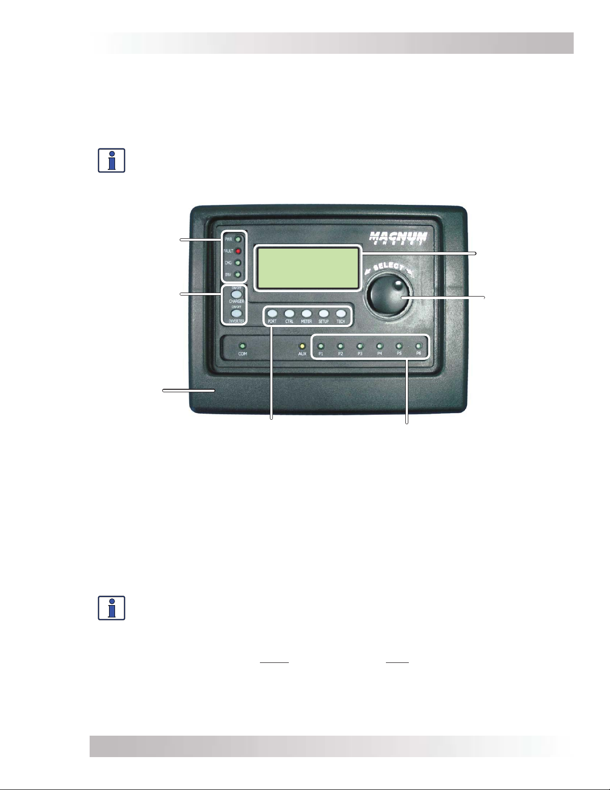
Status
LEDs
ON/OFF
Buttons
Inverting
FacFault Gen Off
29.3VDC -99.0ADC
ALL System Home
LCD Display
Rotary
SELECT Knob
Front
Cover
PORT, CTRL, METER,
SETUP, TECH Buttons
Comm
LEDs
Figure 1-1, Front Panel Features
The ME-RTR is equipped with the following features:
• Status LEDs (x4) – The at-a-glance LEDs provide the inverter/charger status in a
straightforward way.
• LCD Display – The LCD display is a 20 x 4 line (80 characters total) alphanumeric display
used for setting up the inverter/charger operation, as well as viewing current status or fault
messages.
• ON/OFF Buttons (x2) – The ON/OFF buttons allow all the connected inverters or chargers
to be quickly enabled or disabled.
Info: The router’s ON/OFF INVERTER and ON/OFF CHARGER buttons function normally
when a ME-ARC is connected through the router in a parallel system.
• Rotary SELECT Knob – The rotary encoder knob is similar to a car dash radio knob and is
used to quickly scroll through Ports 1-6, or to select various menu items and settings. Pressing
this rotary knob allows you to select a menu item or to save a setting, once it is displayed on
the LCD.
• Comm LEDs (x6) – The at-a-glance LEDs provide the connection statuses of the communication
ports.
• Front Cover – Removable front frame cover, allows access to the cable connections and
mounting holes.
© 2014 Magnum Energy, Inc.
Page 1
Page 10
Introduction
• Menu Buttons (x5) – Allow the inverter or charger to be confi gured to your specifi c system
preferences. These buttons also allow simple access to menu items that can help with monitoring
and troubleshooting your inverter/charger system.
PORT Button – This button accesses the six communication and accessory ports to display
information on the connected devices.
CTRL Button – This button is used to select inverter, charger, and AGS functions previously
set up using the SETUP button.
METER Button – This button is used to access ‘read only’ DC, AC, Timer, AGS, and BMK
meters.
SETUP Button – This button is used to access the setup menus for the inverter, charger,
AGS, and BMK. The SETUP button may be password protected to keep unauthorized users
from accessing the SETUP menus.
TECH Button – This button is used to access technical information, fault history, and to set
a password for the SETUP button.
• Auxiliary (Aux) Relay – The ME-RTR provides an Auxiliary Relay (Item G below)that can be
programmed to work either as a voltage-controlled relay (stays opened or closed based on VDC,
and activates either as an active high or active low type relay with an adjustable time delay),
a SOC-controlled relay (stays opened or closed based on the battery’s state of charge*), or
used as an inverter fault detection relay (opens if an inverter fault occurs). See Section 2.9 for
more information on this relay, as well as how to wire and set up the Aux Relay (using CTRL
button’s 04 RTR Aux Relay menu).
* Requires the optional ME-BMK (Battery Monitor Kit) to be installed.
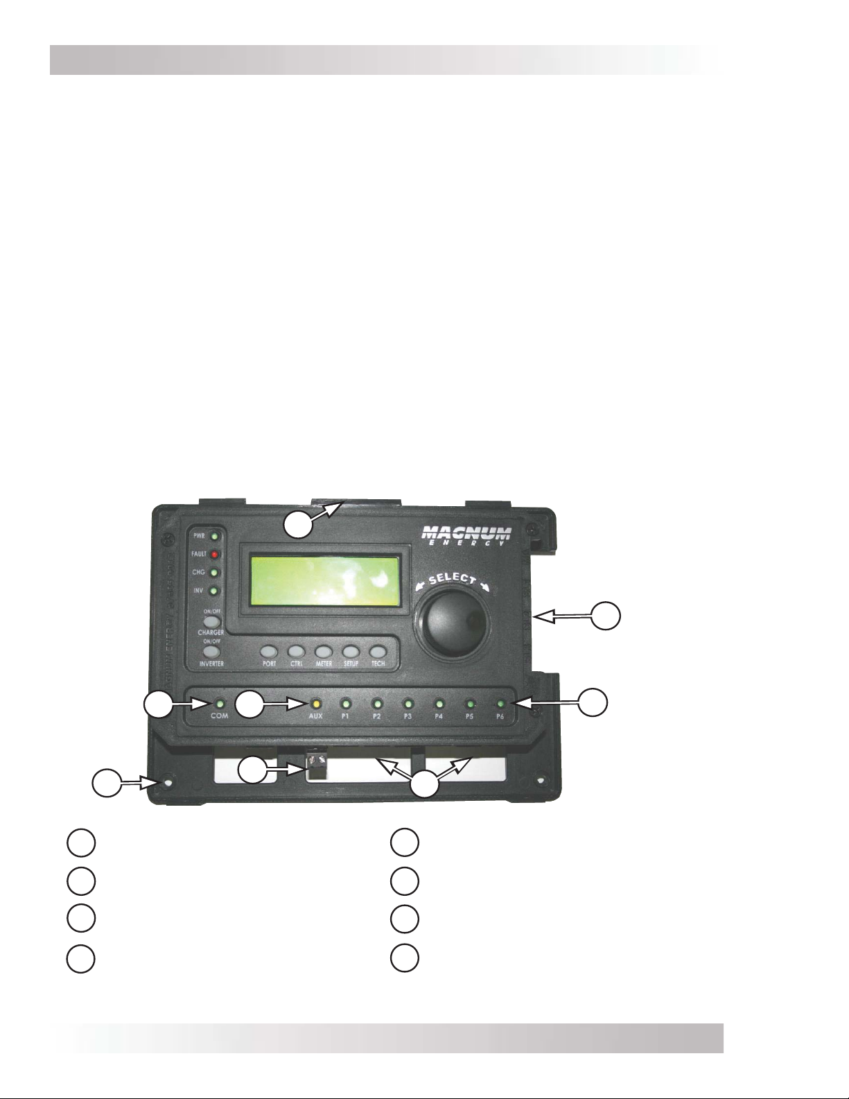
A
B
C
ED
G
F
Mounting tabs for front
cover
Parallel Stack ports (x4)
Six LEDs for communication
(P1-P6)
A
E
F
G
B
C
H
LED for Aux Relay operation
Mounting screw holes (x4)
Aux Relay 2-wire terminal
w/ removable plug
D
Page 2
LED for future use
(not functional)
Figure 1-2, Router Features (front cover removed)
H
Six Comm (Communication) ports
(P1-P6)
© 2014 Magnum Energy, Inc.
Page 11

Installation
2.0 Installation
Review this section and the important safety information on page ii before proceeding with the
installation of your router.
WARNING: Installations should be performed by qualifi ed personnel, such as a licensed
or certifi ed electrician. The installer determines which safety codes apply and ensures
all applicable installation requirements are followed. Applicable installation codes vary
depending on the specifi c location and application.
CAUTION: When connecting battery power to the inverter, all battery negative
connections must be connected prior to the battery positive connections. When removing
battery power from the inverter, the battery positive should be removed before any
battery negative connections are disconnected. This prevents any communication chips/
lines from becoming the DC return path to the battery—causing permanent damage to
all connected accessories.
Summation: Ensure all battery negative circuits are always connected before connecting
or disconnecting battery positive.
2.1 Pre-Installation
Before proceeding, read the entire Installation section to determine how you are going to install
your ME-RTR router. Save time and avoid common, costly mistakes by thoroughly planning the
installation before you start.
2.1.1 Inverter Requirements
The router is used to control multiple Magnum inverters that are normally connected in parallel.
Each connected inverter must: be the same model (i.e., two MS4024PAEs), use the same settings,
and be connected to the same battery bank. If the inverters are not stacked, see Appendix C.
2.1.2 Installation Guidelines
• Before connecting any wires, determine the router’s cable route throughout the home or vehicle/
boat—both to and from the inverter.
• Always check for existing electrical, plumbing, or other areas of potential damage BEFORE
drilling or cutting into walls to mount the router.
• Make sure all wires have a smooth bend radius and do not become kinked.
• If installing this router in a boat, RV or truck, ensure the conductors passing through walls,
bulkheads, or other structural members are protected. This minimizes insulation damage (such
as chafi ng) which can be caused by vibration or constant rubbing.
2.1.3 Unpacking and Inspection
Carefully remove the ME-RTR router from its shipping container and inspect all contents. Verify
the following items are included:
• ME-RTR router (
• Two 6’ RJ14 remote cables (see Figure 2-4)
• Two 6’ RJ45 stack cables (see Figure 2-5)
• Four #8 x 3/4 Phillips screws (for wall mounting)
• ME-RTR Owner’s Manual
If items appear to be missing or damaged, contact an authorized Magnum Energy dealer or
Magnum Energy.
IMPORTANT: Save your proof-of-purchase as a record of your ownership; it is needed if the unit
should require in-warranty service.
2.1.4 Tools Required
Installing the router is simple and requires the following tools:
• Phillips screwdriver • Level • Drill
• Cut-out tool (knife/saw) • Pencil • Drill bit (7/64”)
with removable front cover)
© 2014 Magnum Energy, Inc.
Page 3
Page 12
Installation
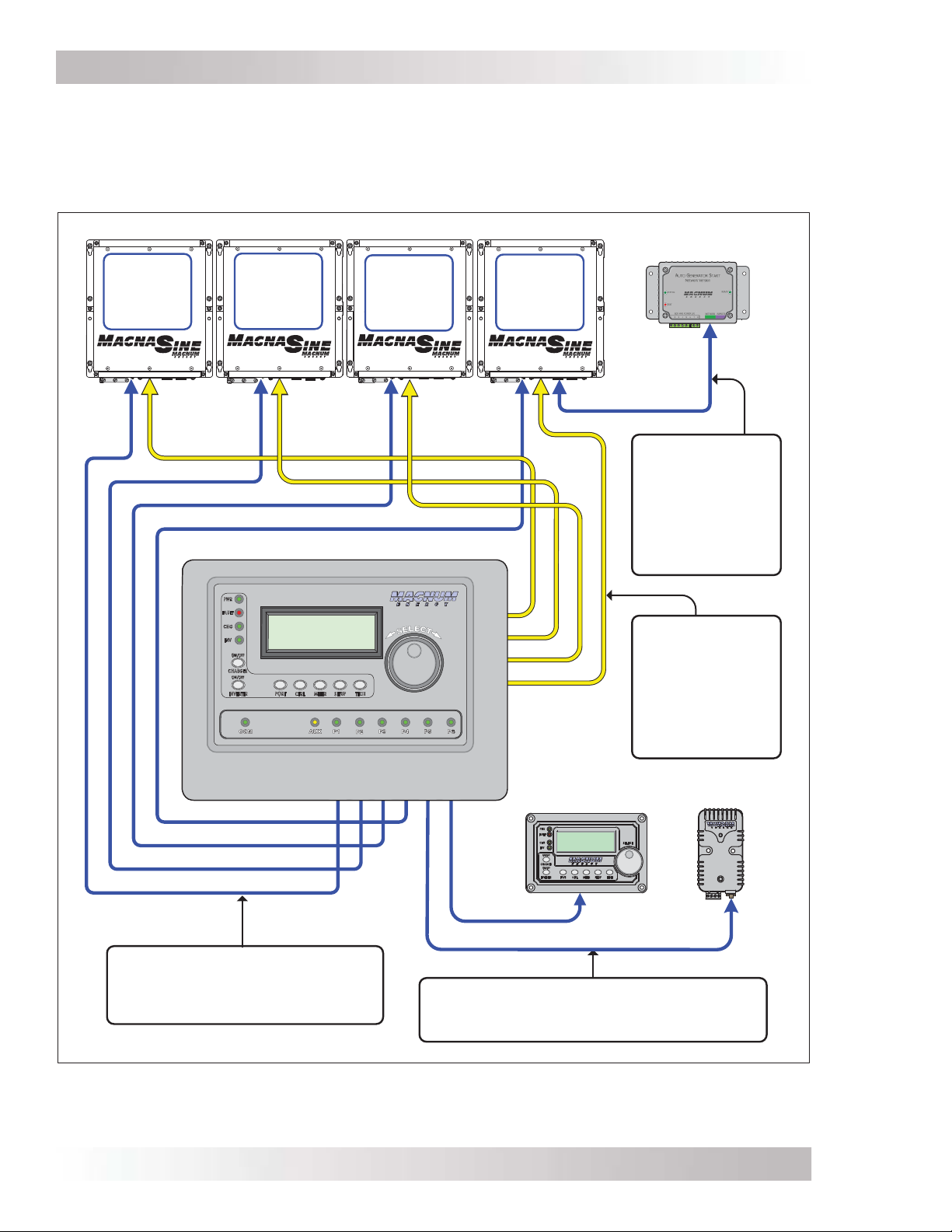
2.2 Installation Overview
The simplifi ed system diagram shown in Figure 2-1 should be reviewed to assist you in planning
and designing your installation. This drawing is not intended to override or restrict any national
or local electrical codes, nor should it be the determining factor as to whether the installation is
compliant—that is the responsibility of the electrician and the onsite inspector.
ME-AGS-N
#1
MS-PAE
I
NVERTER
(MASTER)
#2
MS-PAE
I
NVERTER
(SLAVE 1)
#3
MS-PAE
I
NVERTER
(SLAVE 2)
#4
MS-PAE
I
NVERTER
(SLAVE 3)
Network or
Remote cable
from
ME-AGS-N to
Network Port
(green)
P1 P2 P3
REMOTE cables (x4) from
router to each inverter’s
REMOTE Port (blue)
MA
SL1
SL2
SL3
Stack cables
(x4) from
router to each
inverter’s
Stack Port
(red)
P4
P5 P6
ME-ARC
ME-BMK
Cables from router to ME-BMK and
ME-ARC, or to ME-AGS-N
Figure 2-1, System Overview
© 2014 Magnum Energy, Inc.Page 4
Page 13
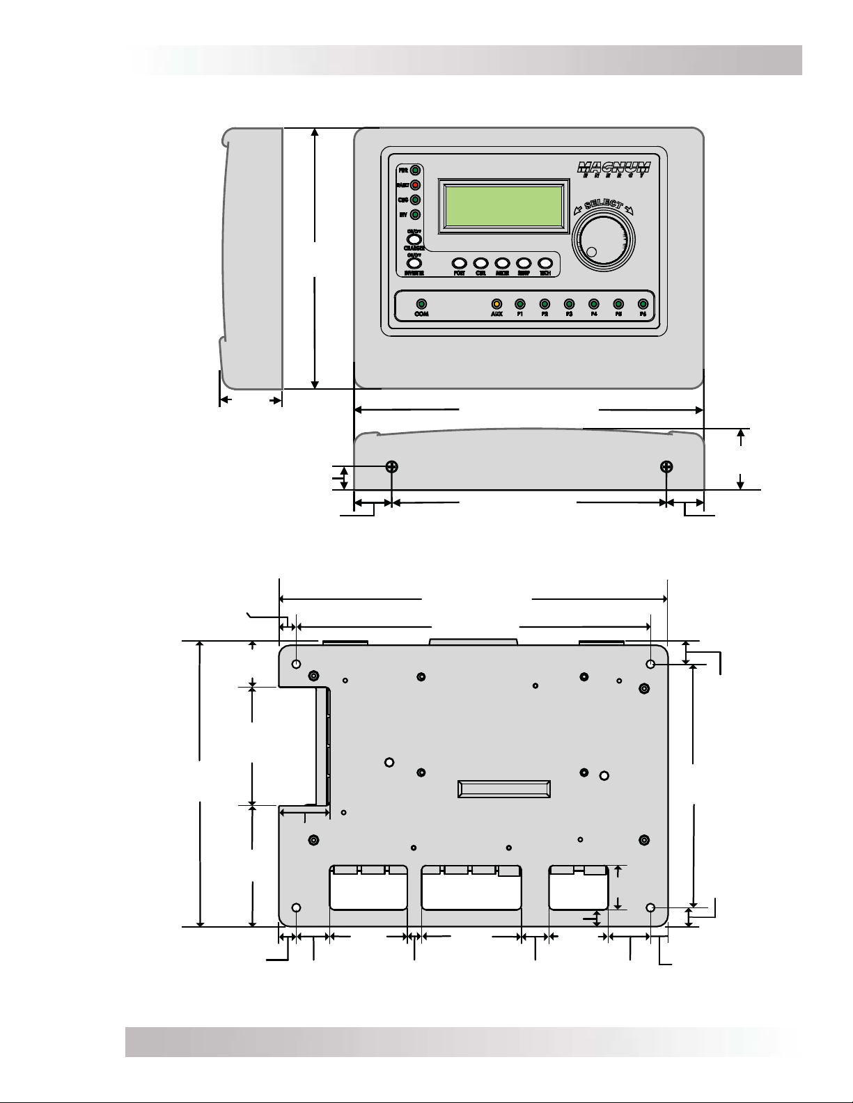
2.3 Router Dimensions
Installation
RIGHT
SIDE
1
9/16"
(4 cm)
BOTTOM
VIEW
Figure 2-2, Router Dimensions (with Front Cover)
3/8"
(0.9 cm)
6
5/8
(16.8 cm)
5/8
"
(1.6 cm)
15/16
(2.4 cm)
"
FRONT
VIEW
8
15/16
"(22.7 cm)
1
9/16
"
(4 cm)
7
1/16
"
" (17.9 cm)
15/16
"
(2.4 cm)
8
3/4" (22.2 cm)
8" (20.3 cm)
1
1/16"
(2.7 cm)
6 7/16"
(16.4 cm)
2 11/16"
(6.8 cm)
2 3/4"
(7 cm)
3/8"
(0.9 cm)
A
1 3/16" (3 cm)
(4.5 cm)
1 1/8"
(2.9 cm)
Figure 2-3, Router Mounting Holes and Cutout Sections (back)
© 2014 Magnum Energy, Inc.
1 3/4”
5/16"
(0.8 cm) (1.6 cm)
2 1/4”
(5.7 cm)
5/8"
BCD
3/8"
5/16"
1
(3.3 cm)
(3.5 cm)
1"
(2.5 cm)
1 3/8"
1/2"
(1.3 cm)
5 1/2"
(14 cm)
7/16"
(1.1 cm)
3/8"
(0.9 cm)
Page 5
Page 14
Installation
2.4 Communications Cables – Provided
With the purchase of the ME-RTR router, Magnum has included four six-foot, yellow communication
cables. These cables—shown below—are provided to make connections between the router and
your Magnum inverter easier and code compliant. Two of the communications cables are remote
(RJ14) cables, two are parallel stack (RJ45) cables.
Most of the systems that use the router will also use an enclosure that includes the components
required in a parallel inverter system (i.e., Magnum’s panels). The NEC/CEC requires the insulation
of all conductors inside the enclosure to be rated for the highest voltage present. The router is
designed to work with 120/240 VAC inverters, therefore, the voltage rating of the communications
cables inside the enclosure must be rated for 300 volts or higher to be code compliant. These
communications cables have 300-volt rated insulation, to meet NEC/CEC requirements DO NOT
substitute for the supplied cables—most cables do not have the properly rated insulation.
Info: These cables carry less than 30 volts and are thus considered a “limited energy
circuit”, which is normally not required to be installed in conduit.
Info: Additional stack cables are available with the purchase of a Magnum MPX Series
enclosure. Stack cables are not sold separately. If NEC/CEC requirements do not apply,
a CAT 5 cable (RJ45/8P8C) can be used. However, this CAT 5 cable must be no longer
than 6 feet—this ensures there is no communication issue as these cables transmit/
receive high speed data.
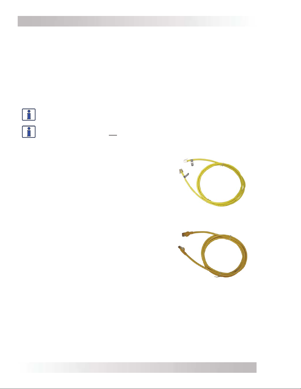
Figure 2-4 shows a ‘REMOTE’ cable (two are supplied).
This cable is 6’ (1.83m), with a RJ14 6P4C (6-position/4conductor) telephone-type male connector and a blue
REMOTE label on each end. It comes with 300-volt rated,
yellow insulation. One end of this cable is connected to
one of the communication ports (P1-P6) on the router
(see Figure 2-6 or 2-7), and the other end is connected
to the inverter’s Remote port (normally routed inside
the MP enclosure) as shown in Figure 2-10.
Figure 2-4, Remote (RJ14) Communication Cable
Figure 2-5 shows a ‘STACK’ cable (two are supplied).
This cable is 6’ (1.83m), with a RJ45 8P8C (8-position/8conductor) connector on each end. It comes with 300volt rated, yellow insulation. One end of this cable is
connected to one of the stacking ports (MA-SL3) on the
router (see Figure 2-11), and the other end is connected
to the inverter’s Stack/Accessories port (normally routed
inside the MP enclosure) as shown in Figure 2-10.
Figure 2-5, Parallel Stack (RJ45) Communication Cable
2.4.1 Network Cable
A network cable is not supplied with the router, but is included with the purchase of Magnum’s
networked accessories (i.e., ME-AGS-N, ME-BMK). If stacking inverters on Magnum’s MP Series
enclosures, the regular network cable must be replaced with a high voltage network cable, which
is included with the purchase of the MP Series enclosure. This cable has 300-volt rated yellow
insulation, is 6’ (1.83m) long, and has a RJ14 6P4C (6-position/4-conductor) telephone-type
male connector on each end. One end of this cable is connected to the accessory, and the other
end is connected to the router’s Comm port or the inverter’s Network port (see Figure 2-11). This
cable is wired similar to the remote cable, and can be substituted for the remote cable, if needed.
© 2014 Magnum Energy, Inc.Page 6
Page 15
Installation
2.5 Communications Cable Routing
Before mounting the router on a wall, determine whether to surface mount or to conceal the cable
connections to the router. The cables can be fl ush-mounted—concealed—through an opening in a
wall (Figure 2-6); or, if there is insuffi cient room behind the wall or no desire to cut into the wall,
the cables can be surface-mounted (Figure 2-7).
Info: If the router is being installed on a Magnum panel enclosure (MP), a router
mounting bracket is provided with the Magnum panels. This bracket can be attached
to either the left or right-hand side. Refer to the MP Owner’s manual (PN: 64-0028) for
information on mounting the router on a MP panel.
Figure 2-6, Concealed Mounted
Remote/Network Cables
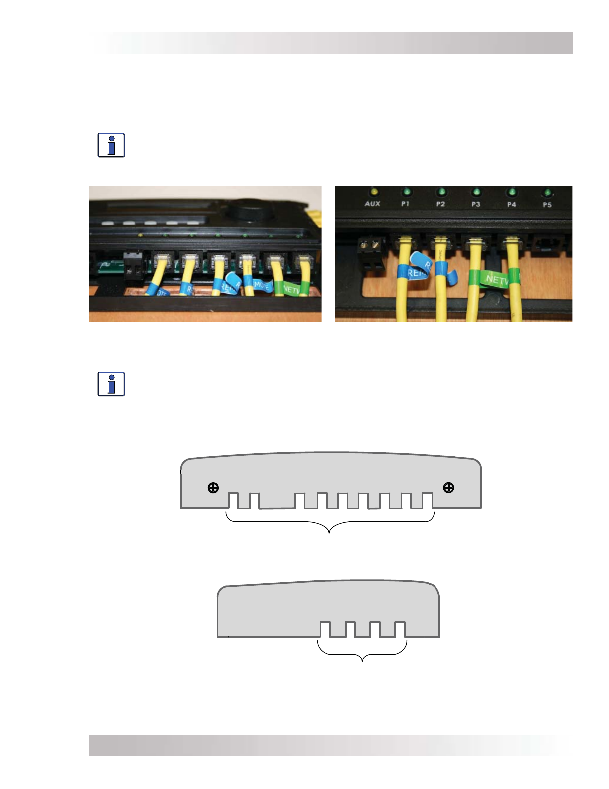
Info: If the cables are installed on the surface, the router’s front cover has cutout
sections to accommodate the cables (see Figure 2-8). These cutout sections are made
thinner to allow them to be easily broken or cut. Only remove those cutout sections
needed for the number of cable connections you are installing.
Figure 2-7, Surface Mounted
Remote/Network Cables
BOTTOM VIEW – ROUTER COVER
Remote and network cable cutouts (x9)
RIGHT SIDE VIEW – ROUTER COVER
Figure 2-8, Router Front Cover’s Cable Connection Cutouts
© 2014 Magnum Energy, Inc.
Stack cable cutouts (x4)
Page 7
Page 16
Installation
2.6 Mounting the Router on a Wall
CAUTION: The router must be located close to the inverter/chargers (within six feet).
The router is designed to exchange data from the master inverter with one or multiple
slave inverters. The high speed communication data between the stack ports on the
router and the inverter ensure the slave inverters are synchronized to the master
inverter. To ensure the communications is not impacted, DO NOT exceed the 6-foot
stack cable distance between the router and each connected inverter.
Info: If a more distant monitoring location is required (more than six feet), a ME-RC50
or ME-ARC50 remote control may be connected and acts as a remote on/off switch to
assist in monitoring the system. See Section 9.0 for more information.
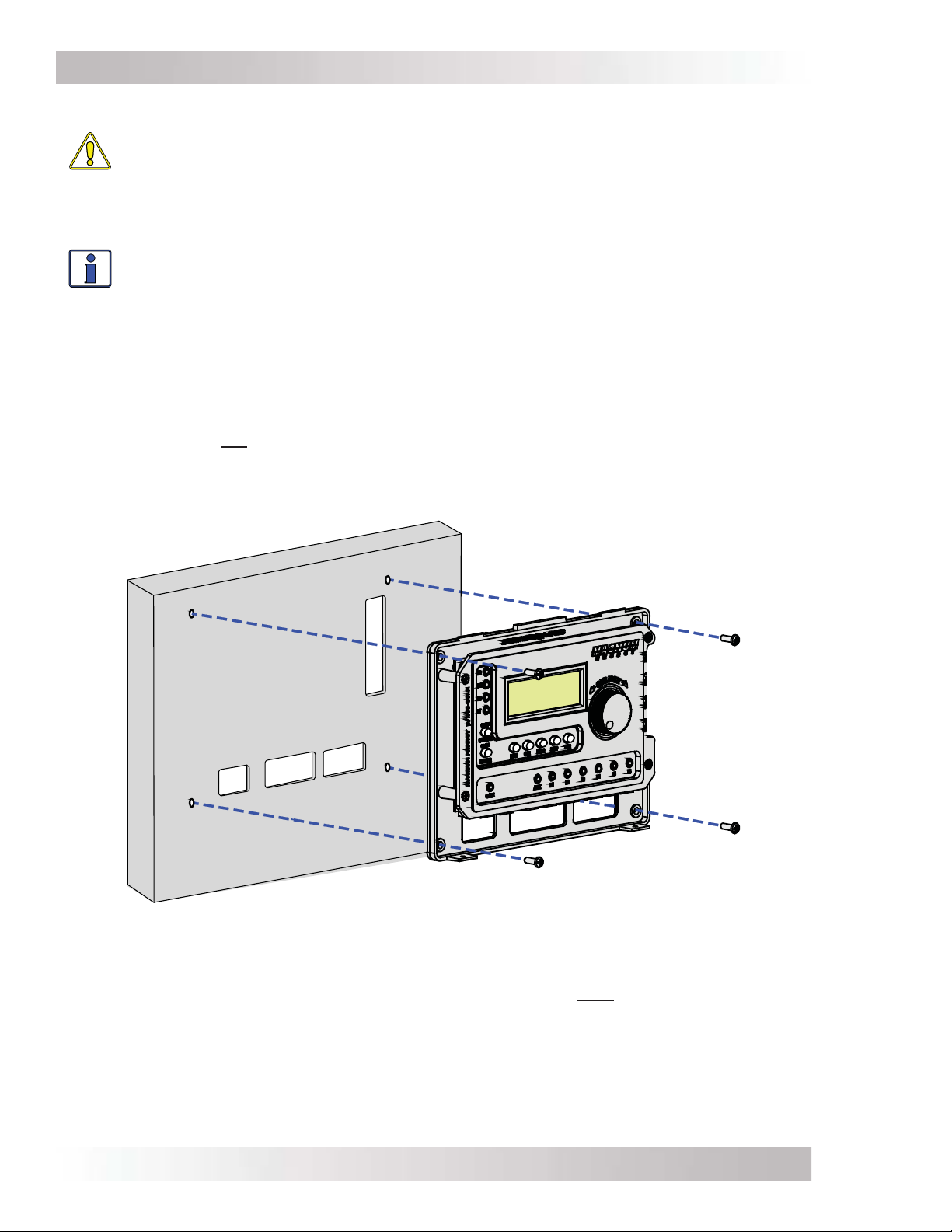
To mount the router on the surface of a wall:
1. Select an appropriate location to install the router (see Figures 2-2 & 2-3 for the router’s
dimensions).
2. Remove the router’s front cover, and then use the router bezel as a template to mark the
screw holes and the sections of the wall (or mounting surface) to remove to accommodate the
routing of the communication wires (Sections A-D on Figure 2-9).
Note: If you are not routing the communication wires thru the wall, there is no need to cut
sections from the wall.
3. Once the screw holes have been drilled and the optional wall sections are removed, mount the
router bezel to the wall using the 4 screws that are provided.
Cutout sections A-D to
accommodate routing
wires behind wall.
A
B
C
Figure 2-9, Mounting the Router to a Wall
2.7 Connecting the Communication Cables
The stack and remote communication cables are used to connect each inverter/charger directly
to the router. A network cable is used to connect accessories to the router.
Each paralleled inverter/charger requires a high speed parallel stack cable connected to a stack
port on the router—marked MA (Master), SL1 (Slave 1), SL2 (Slave 2), and SL3 (Slave 3)—see
Figure 2-1. One inverter/charger will always be designated the “Master”, and subsequently any
other connected inverter/chargers are designated as “Slaves”. You can stack up to four MS-PAE
or MS-PE Series inverter/chargers using one router. It is recommended that you set up the Master
inverter as the fi rst unit on the left, and Slave 1 as the second unit, etc.
D
© 2014 Magnum Energy, Inc.Page 8
Page 17
Installation
Once the stack cables are connected, coordinate the remote cables to the communications ports
so that the Master inverter is connected to Port 1 and the Slave 1 inverter is connected to Port
2 (the remote and stack cables are connected to the inverters in order from left to right—MA
(Master), SL1, SL2, and SL3). This confi guration makes it easy to keep track of which inverter is
displayed on each port, and allows you to identify the master and slave units without having to
trace the wires from the router to each inverter.
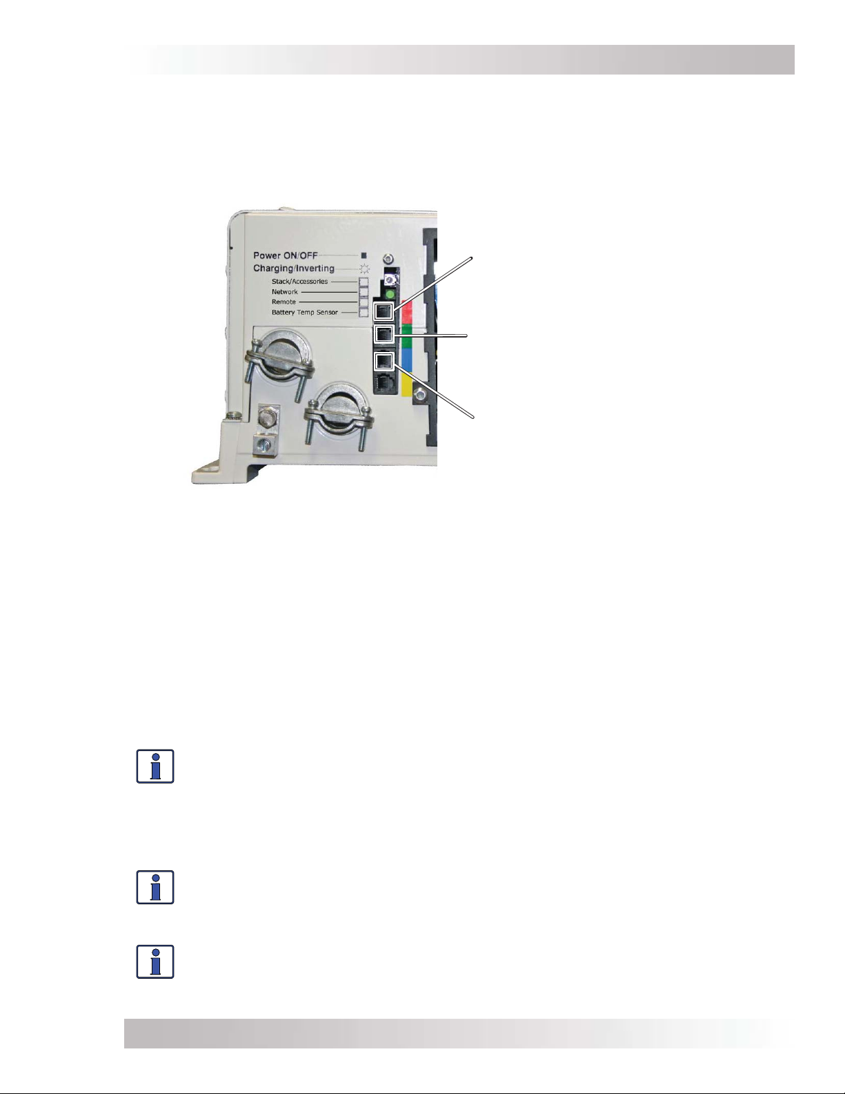
Connect the parallel stack cable
to the top port (red) marked
“Stack/Accessories.”
Connect the network cable to the
port (green) marked “Network.”
Connect the remote cable to the
port (blue) marked “Remote.”
Figure 2-10, Connecting the Parallel Stack and Remote Cables to an Inverter
2.7.1 Connecting the Remote/Network Cables
To connect the remote cables:
1. Connect a remote cable to the Remote port on every inverter installed in parallel (see Figures
2-1 & 2-10), using the supplied cables.
2. Route the inverter-connected remote cables from each inverter/charger to your router. Follow
the same route you used for the stack cables.
3. Connect each remote cable to its respective communication port on the router (P1-P6 per the
number of inverters installed in parallel). Refer to Section 2.4 and Figures 2-6 & 2-7.
4. Connect any accessories to the remaining open communication ports on the router using a
network cable.
Info: A maximum of four inverters can be connected to a router to work in parallel with
each other. If the maximum number of inverters are connected, two open ports remain.
If a ME-ARC or ME-RC remote is connected to a router, it must be connected directly to
a remote communication port on the router. If there are still open communication ports
on the router, connect any accessories—such as an ME-AGS-N or ME-BMK—directly to
the router first. Then, if all the router’s communication ports are being used and there
are additional accessories, they may be connected to the Network ports on the inverters.
Info: Any accessory connected directly to the Network port on an inverter will display
as an accessory on the router port to which that inverter is connected.
Example: A ME-AGS-N connected to the Network port on the master inverter (P1) will
display as P1A on the router.
Info: Multiple accessories of the same type may be connected to the system, but there
are limitations to the number of accessories. You may connect a maximum of one MERC or ME-ARC remote, two ME-AGS-N modules, and up to six ME-BMK/ME-BMK-NS
accessories.
© 2014 Magnum Energy, Inc.
Page 9
Page 18
Installation
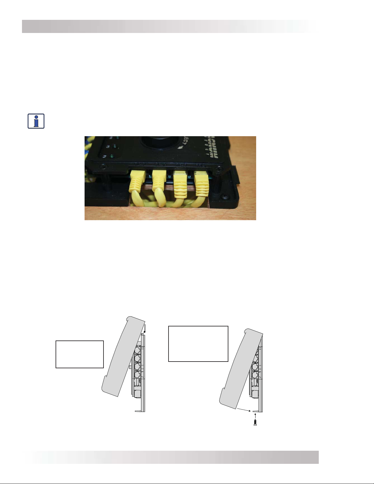
2.7.2 Connecting the Parallel Stack Cables
To connect the parallel stack cables:
1. Connect a stack cable to the Stack/Accessories port on every inverter installed in parallel (see
Figures 2-1 & 2-10).
2. Route the inverter-connected stack cables from each inverter/charger to your router. Depending
on your particular setup, the cables may need to be routed through walls or the MP panel
enclosure system.
3. Connect each stack cable to its respective stack port on the router (MA, SL1, SL2, and SL3
ports for the appropriate number of inverters installed in parallel). See Figure 2-11.
Info: At least one stack cable must be plugged into the router’s MA port in order for
the router to operate any inverters.
SL3
SL2
SL1
MA
Figure 2-11, Connecting the Parallel Stack Cables to the Router
2.8 Installing the Router’s Front Cover
Once all the wiring is completed, you are ready to re-install the front cover (if using the Aux Relay,
refer to Section 2.9 before re-installing the front cover). If you have surface mounted your router,
you must fi rst remove those cutout sections from the front cover that are needed for the number
of cable connections you have installed (see Figure 2-8).
Tip the top of the front cover down and hook it over the router top (protruding horizontal tabs on
inside top of the front cover go under corresponding mounting tabs at top of router), and then
drop the front cover down (cover the router’s bottom vertical tabs). Install the two fl athead Phillips
screws into the bottom tabs to hold the front cover in place (see Figure 2-12).
Push front cover
down fl ush, and
Place front
cover over
tabs at top.
install screws in
bottom tabs.
Figure 2-12, Installing the Router’s Front Cover
© 2014 Magnum Energy, Inc.Page 10
Page 19
Installation
2.9 Wiring the Auxiliary (Aux) Relay
The Aux Relay provides a 2-wire dry contact relay (i.e., no voltage provided) that is either open
or closed, and can be wired to any device requiring a contact closure to operate. For example, it
can be used as a signal relay to power a higher current relay.
Relay Information
• A single-pole, single-throw relay provided with the NO (Normally Open) and COM contacts.
• Contact rating: up to 30 VDC @ 1 amp, and from 31 VDC up to 60 VDC @ .25 amp.
• Opens if power to the router (provided through the inverter remote cable) is lost.
• Provides “dry contact” connections (it does not provide any voltage or current)—power for any
external device requiring voltage or current must be provided through the relay.
• This relay is not intended to directly provide power. Rather, this relay can be used to send a
signal to operate the coil of another higher amperage device that does the actual switching
of power.
CAUTION:
• Any voltage connected to the relay must be less than or equal to the relay’s contact
ratings (Contact Ratings: ≤ 1A up to 30 VDC, ≤ .25A from 31 VDC to 60 VDC).
• An in-line fuse rated up to 1 amp (up to 30 VDC) or .25 amp (from 31 VDC to
60 VDC) must be used to protect all power circuits connected to the Aux Relay
(do not fuse ground connections). The fuse should be located as close as possible
to the power source. A fuse must be used, even if the circuit is providing only a
“dry contact” or “ground” connection—it will prevent damage if the connection is
miswired or damaged. Ensure the fuse is correctly rated for the wire size used. Refer
to national and local codes for rating and type.
• The Aux Relay circuit is not rated for AC volts and may cause damage if used.
• The warranty does not cover damage to this relay.
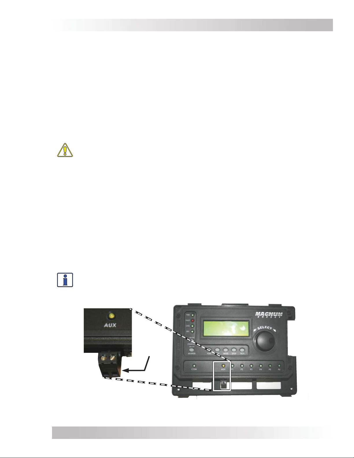
Relay Terminal Block
The Aux Relay is wired through an Euro-style removable connector (Figure 2-13). The connector
provides a two-port screw-type terminal block for wiring. This terminal block is friction-fi t into the
connector and can be removed by pulling it straight out. Each port on the terminal block accepts
a CU/AL single wire from #28 to #12 AWG (0.3 to 2.3 mm²).
Info: For information on setting the Aux Relay, refer to the CTRL: 04 RTR Aux Relay
menu.
2-wire dry
contact
terminal
Figure 2-13, Wiring the Auxiliary Relay
© 2014 Magnum Energy, Inc.
Page 11
Page 20
Setup
3.0 Setup
When a router is connected to a Magnum inverter/charger, the settings in the router determine the
inverter/charger’s operating parameters. This section shows you how to navigate the router and
gives you an understanding of the function of each adjustable setting. See Figures 4-1 through 4-5
for complete maps of the router’s menu items and adjustable settings.
*** IMPORTANT ***
All settings/setup menus in the router are compatible with MS-PAE/MS-PE Series inverter/
chargers. If you are using the router with an inverter/charger other than the MS-PAE/MS-PE
Series, some features and setup menus may not be compatible and will not function. Refer to
Appendix B to determine if a particular feature/setup menu is compatible with your inverter.
Refer to Appendix C for additional information on using the router with non-stacked inverters.
3.1 Power-up Routine
When the router is first connected to an inverter, a power-up routine is initialized. During the
power-up routine, the LCD displays “MAGNUM ENERGY, Self Test, ME-RTR, and Version 3.1” for
approximately 5 seconds. The next three Set System Clock screens prompt you to set the current
time (HOURS, MINUTES, and AM/PM). Once the clock is set, the System Home screen is displayed.
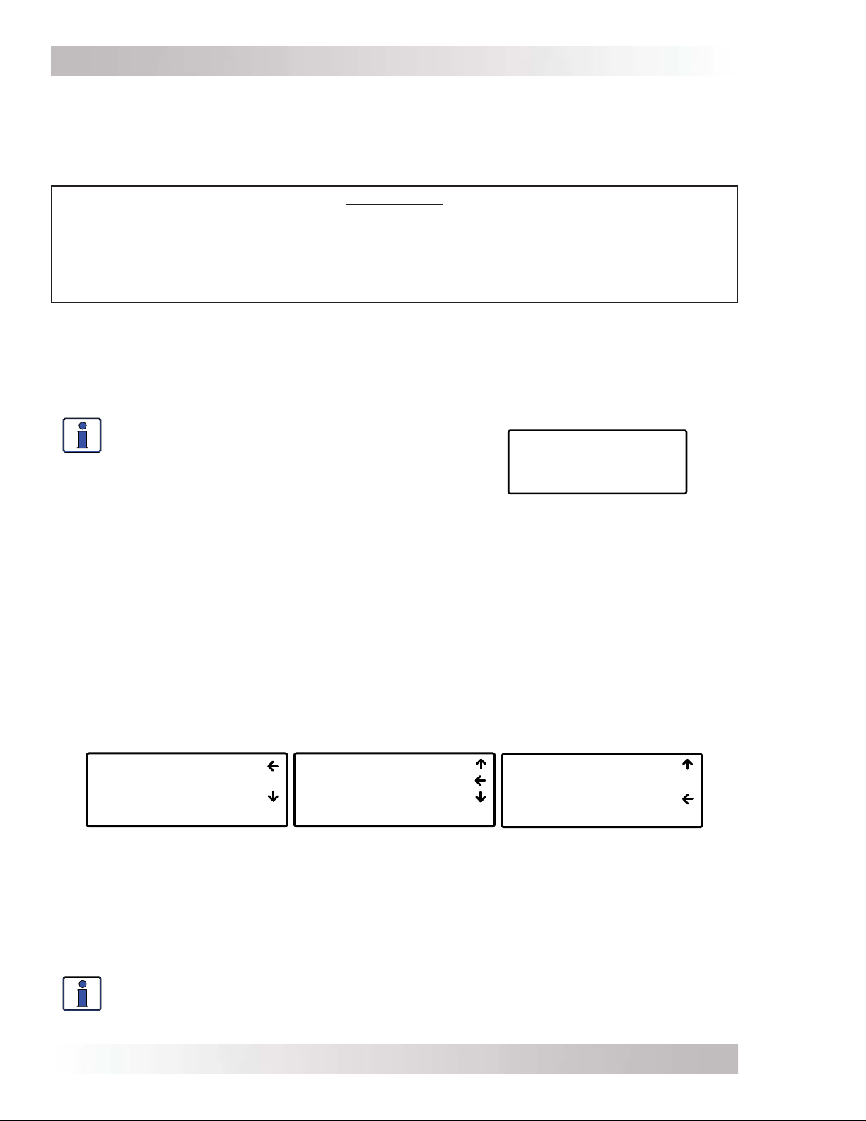
Info: Pressing and holding down the METER button
for three seconds takes you back to the System
Home screen (Figure 3-1) from any menu. The
LCD display automatically returns to the System
Home screen if no buttons have been pressed for
fi ve minutes.
Figure 3-1, System Home Screen
Off
29.3VDC 0ADC
ALL System Home
3.2 Navigating the Router
Familiarize yourself with the controls on the front panel which are used to fi nd, adjust, and save
the desired settings (refer to Figure 1-1). They are:
• LCD Display – The 4-line LCD display shows status and operation information for the inverter/
charger and any attached accessories. All setup menus and faults also appear on the LCD display. If
there are more choices than will fi t on the screen, up and down arrows are present to guide you in
accessing those choices. An up arrow indicates you must rotate the SELECT knob counterclockwise
to display the next line. A down arrow requires a clockwise rotation. If both an up and down arrow
display, rotate the SELECT knob clockwise or counterclockwise to display all the hidden lines. See
Figure 3-2 below for an example of a screen sequence.
01 DC Meters
02 AC Meters
03 Timers
ALL Select METER
Figure 3-2, Up and Down Arrows for Hidden Lines
• Menu Buttons (x5) – These buttons allow simple access to menu items for confi guring,
monitoring, and troubleshooting your inverter/charger system.
• Rotary SELECT Knob – This rotary knob allows you to quickly scroll through and select various
menu items and settings. Pressing the knob selects the menu item to change, or saves the current
selection.
Info: The “←” (left facing arrow) symbol indicates that the displayed setting has been
selected and will be used (if the menu item is blinking, it has not yet been selected;
press the SELECT knob to select that menu item). Refer to Figure 3-2 for an example.
02 AC Meters
03 Timers
04 AGS Meters
ALL Select METER
03 Timers
04 AGS Meters
05 BMK Meters
ALL Select METER
© 2014 Magnum Energy, Inc.Page 12
Page 21
Setup
3.3 Router Buttons and Menu Items
The fi ve menu buttons (PORT, CTRL, METER, SETUP, and TECH) allow the inverter/charger system
to be confi gured to your specifi c preferences. These buttons also allow you to access menu items
that can help with monitoring and troubleshooting your system.
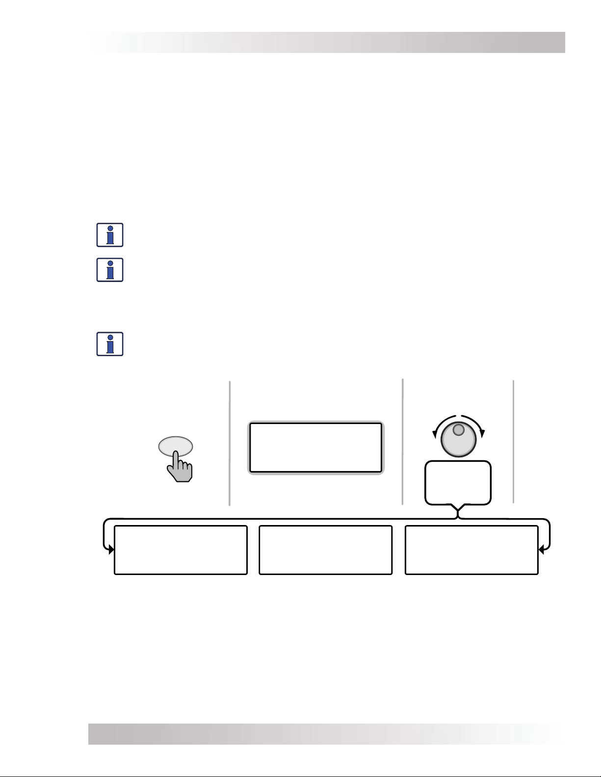
3.3.1 PORT Button and Menus
The PORT button allows you to access each active communication port. The communication port
can be one of the six ports at the bottom of the router, or it can be a Remote (blue) or Network
(green) port on the inverter. An inverter or accessory must be connected to a communication port
in order to be programmed and to display status info.
As you press the PORT button, the home screen menu (“Home” appears in the bottom right corner
of the router’s LCD display) for each device that is communicating with the router is shown. Each
home screen provides information and the status of the connected device.
Info: When you are at a specifi c device’s home screen, you can directly access the
meter and setup menus for that device by pressing the METER or SETUP button.
Info: When an accessory is plugged into a communication port (P1-P6) on the router,
the PORT button displays the accessory as the corresponding port (i.e., in Figure 3-3
below, Port 3 shows “AGS Home”). If an accessory is plugged into the Network port on
one of the parallel inverter/chargers, the PORT button displays the accessory as “P#A”
(i.e., a ME-AGS-N plugged into a parallel inverter/charger that is plugged into Port 1
would display as “P1A”).
Info: After pressing the PORT button, use the SELECT knob to scroll through all the
active ports, as well as all empty router communication ports.
From System Home
screen:
All Ports screen
displays
OR rotate to
next port
1 INV 2 Empty
PORT
Press
MS4024PAE Master
Inverting
29.3VDC 0ADC
P1 INV Home
3 AGS 4 BMK
5 Empty 6 Empty
ALL Port Home
Press PORT button to
access next active port.
Auto Gen Start
Gen Off 0.0Hrs
28.8VDC TS Open
P3 AGS Home
...
Figure 3-3, PORT Button
Rotate to
desired
selection:
Empty Port
P6 Home
...
© 2014 Magnum Energy, Inc.
Page 13
Page 22
Setup
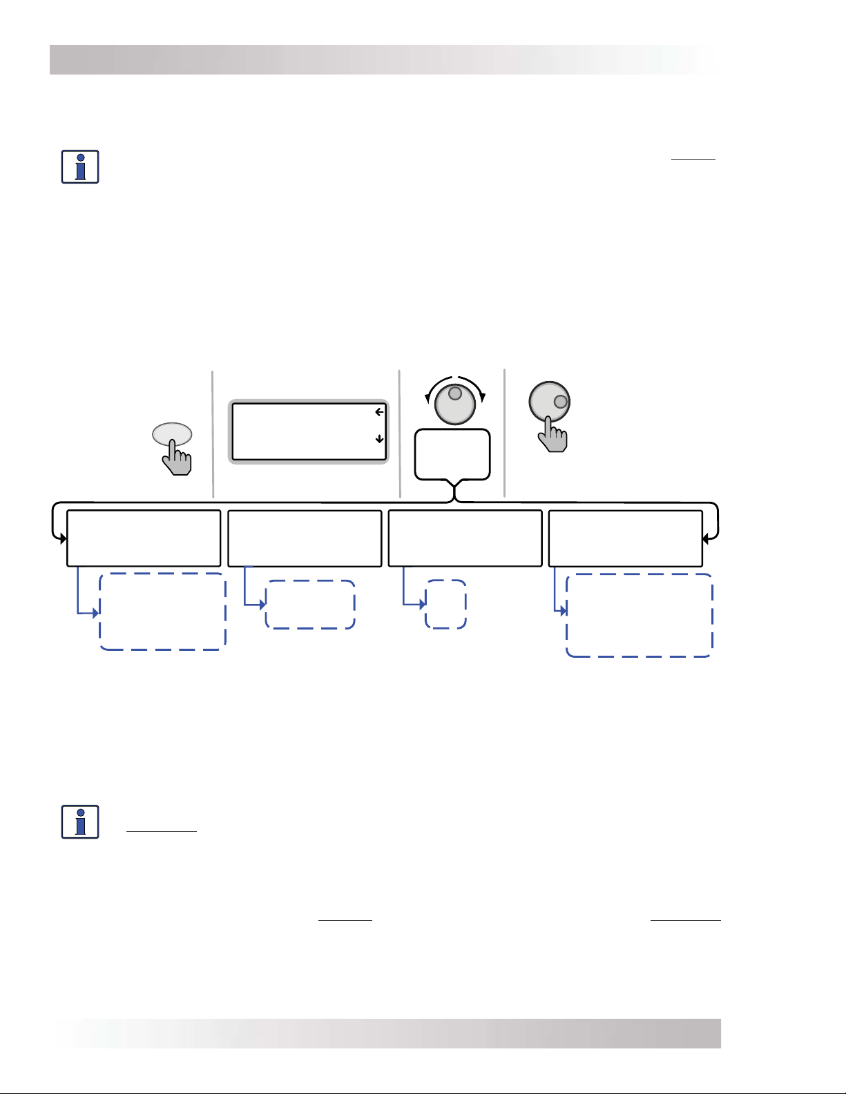
3.3.2 CTRL (Control) Button and Menus
The CTRL button accesses the 01 AC In Control, 02 Charger Control, 03 Gen Control, and 04 RTR
Aux Relay menus.
Info: An AGS must be connected in order for the Gen Control menu to display unless
the TECH: 07 Show all Menus menu has been set to “YES”. Refer to Section 3.3.5 for
more info on the TECH 07 menu. Otherwise, “No AGS Present” appears on the 03 Gen
Control screen.
The CTRL button gives you quick control of the main functions of the inverter/charger without having
to access the SETUP button’s menus in order to change the operation of the inverter/charger or
the generator. Once the settings have been programmed in the SETUP menus, the features can
then be enabled using the CTRL button.
Example: The SETUP menu’s 02C AC In – Time setting is used to set what time of day (e.g., 12AM
to 8AM) you want the inverter to connect to the incoming AC. Once this time is set, use the CTRL
button to access the Set AC In Control menu item and select Time Connect. When Time Connect
is selected, the inverter/charger will only connect to AC when the time is between 12AM and 8AM.
Top lines show menus
01 AC In Control
CTRL
Press
02 Charger Control
03 Gen Control
ALL Select CTRL
Bottom line shows view
Rotate &
press to
select:
Press to
edit setting
01 AC In Control
Auto Connect
ALL View ACI CTRL
Auto Connect
VDC Connect
Time Connect
SOC Connect
AC In - Disabled
02 Charger Control
Multi-Stage
ALL View CHG CTRL
Multi-Stage
Start Float
Start Bulk
03 Gen Control
OFF
P3 View AGS CTRL
OFF
ON
AUTO
04 RTR Aux Relay
Force Open
ALL View SYS CTRL
Force Open
Force Closed
Auto VDC
Auto VDC (BTS Comp)
Auto Fault
Auto SOC
Figure 3-4, CTRL (Control) Button and Menus
CTRL: 01 AC In Control
The 01 AC In Control menu has four different conditions in which the inverter/charger connects
to an incoming AC power source. Only one may be selected at any time—multiple conditions can
be set up and enabled, but only one can be active at any time.
Info: The top status line of the LCD display alternates the inverter/charger status with
a secondary AC IN status when AC is present, but is not connecting as a result of a
setting made in the SETUP menu.
Example: AC is present, but Time Connect has been selected from the 01 AC In Control menu and
the current time of day is 6PM. The SETUP menu’s 02C AC In – Time current setting is 2AM-8AM.
The current time of 6PM is outside the connect time, so the inverter/charger will not connect to
the incoming AC until after 2AM. The primary status will display “Inverting” and the secondary
status will display “ Time Connect” to let you know the reason that incoming AC has not connected.
• Auto Connect: Automatically connects to incoming AC power when the incoming AC is qualifi ed
by the inverter/charger (voltage is below the high AC input requirements, above the SETUP
button’s 03B Low VAC Dropout setting, and between 50 Hz to 70 Hz for domestic models;
40-60 Hz for export models).
© 2014 Magnum Energy, Inc.Page 14
Page 23

Setup
Info: The Auto Connect setting must be selected if the incoming AC source is a
generator. There is no benefi t from using the AC In feature if the AC source is from a
generator—the generator power may not be available if an AC In feature is activated;
because also, when the generator is turned on (autostarted or manually), it may be
prevented from connecting because the criteria to allow the AC input to connect (AC In
is based on time, VDC, or SOC) may not have been met.
Note: This is true unless using an inverter that has two independent AC inputs—one for
grid and the other for generator (i.e., MSH4024RE), because the AC In Control features
only work with the GRID IN (AC1) input.
• Time Connect: Incoming AC only connects when the time of day is between the Connect and
Disconnect time settings in the SETUP menu’s 02C AC In – Time menu item. See SETUP menu
02C on page 27 for a complete explanation of the Connect/Disconnect time menu settings.
• VDC Connect: Incoming AC only connects when the DC battery voltage falls below the Connect
volts setting in the SETUP menu’s 02D AC In – Volts DC menu item. Disconnects from incoming
AC when the DC battery voltage rises above the Disconnect volts setting, also from the 02D
AC In – Volts DC menu. See SETUP menu 02D on page 27 for a complete explanation of the
Connect/Disconnect volts menu settings.
• SOC Connect:
setting in the SETUP menu’s 02E AC In – SOC menu item. Disconnects from incoming AC when
the battery bank SOC rises above the Disconnect setting, also from the 02E AC In – SOC menu.
This feature requires the optional ME-BMK (battery monitor) to be installed. See SETUP menu
02E on page 28 for a complete explanation of the Connect SOC menu settings.
Info: If SOC Connect is selected and the incoming AC connects, the router issues
a one-time “Start Bulk” command to the inverter/charger. This ensures the charger
enters the Bulk/Absorb charge cycle regardless of battery voltage.
• AC In – Disabled: Disconnects incoming AC when selected. This setting prevents the incoming
AC from connecting to the inverter/charger.
CTRL: 02 Charger Control
The 02 Charger Control menu enables you to set the charge mode to Multi-Stage, Start Float, or
to Start Bulk. Most of the time the charger should be left in the Multi-Stage setting, but to override
this setting use the CTRL button and the 02 Charger Control menu. The charger can be forced to
start the Float or Bulk charge mode using the Start Float or Start Bulk settings from this menu.
• Multi-Stage: This charge profi le causes the charger to automatically operate thru the multi-
stage (Bulk, Absorption, and Final Stage) charge cycles. When AC is connected and the charge
mode begins¹, the inverter’s battery voltage is monitored to determine the charging stage. If the
battery voltage is low (≤12.8 VDC/12-volt models, ≤25.6 VDC/24-volt models, or ≤51.2/48-volt
models), the charger begins Bulk Charging. If the battery voltage is high (≥12.9 VDC/12-volt
models, ≥ 25.7 VDC/24-volt models, or ≥ 51.3/48-volt models), the charger skips the Bulk
and Absorb charge stages and goes directly to the fi nal charge stage (Multi-Stage, Float, or
Silent) as selected in the SETUP: 03F Final Charge Stage menu item.
Note¹ – If the SETUP: 03C Battery Type selection is CC/CV, once AC connects and the charge
mode begins, the charger enters the Constant Current charge mode. If the CTRL: 01 AC In
Control setting is “SOC Connect,” or if the SETUP: 03D Absorb Done setting is “SOC”, then the
charger will always enter the Bulk Charge mode once AC is connected and charging begins.
• Start Float: This selection restarts the Float charge cycle from any stage in the charge cycle
as long as the charger is active.
Info: The Start Float selection automatically defaults back to the Multi-Stage setting
once the inverter/charger status displays “Float Charging” (or “Silent” if battery type
CC/CV is selected).
Info: If battery type CC/CV is chosen, the Start Float selection transfers the charger
to Silent mode—unless “Hold CV Chg Volts” is selected, then the charger enters the
Constant Current charge mode.
Incoming AC only connects when the battery bank SOC falls below the Connect
© 2014 Magnum Energy, Inc.
Page 15
Page 24

Setup
• Start Bulk: This selection restarts the Bulk charge cycle from any stage in the charge cycle as
long as AC is present and the charger is active. The Start Bulk selection is useful when a full
multi-stage charge cycle does not bring the specifi c gravity of the batteries to the proper level.
Info: After Start Bulk is selected and activated, the 02 Charger Control selection
automatically returns back to the Multi-Stage setting.
Info: If the current charge mode is Bulk or Absorption, and Start Bulk is selected,
“Already in Bulk/Abs” displays on the router.
Info: If battery type CC/CV is chosen, and the charger is in Silent charge mode, the
Start Bulk selection transfers the charger to Constant Current mode.
Info: If you have to continually restart the bulk cycle in order to bring the batteries to
full charge, check the settings from the SETUP: 03 Charger Setup menu to ensure the
batteries are fully charged at the end of a regular multi-stage charge cycle.
CTRL: 03 Gen Control
03 Gen Control is used for controlling a standby generator that is connected to the system and
using the optional ME-AGS-N module. Once the AGS-N is installed in the system, the generator
can be manually started and stopped, or set to start and stop automatically from this menu.
Note: Options include: OFF (default setting), ON and AUTO.
Info: The AGS-N must be installed in order for the 03 Gen Control menu to control a
standby generator. See the ME-AGS-N owner’s manual (PN: 64-0039) for information.
Info: If a ME-ARC is directly connected to one of the router’s communication ports
(P1-P6), it can be used in a remote location as a remote on/off switch, and can assist
in monitoring the system and controlling a generator that is connected to an AGS-N.
Info: If a ME-ARC is directly connected to the router, the ARC’s CTRL button function is
defeated. However, the Gen Control selection is in the ARC’s FAVS menu, and the gen
can be controlled via the ARC through the FAVS menu, but not through the CTRL menu.
• OFF: The OFF selection will stop the generator by sending a ‘stop’ command from the AGS-N
control module (can be running from either a manual start or an autostart command from the
AGS). The generator will not start automatically if OFF is selected.
Info: If DC power is lost to the router, this menu resets to the default OFF position for
safety.
Info: When OFF is selected, the generator turns off immediately—regardless of any
delay settings (e.g., Cooldown).
• ON: The ON selection starts the generator by sending a ‘start’ command from the ME-AGS-N
control module. Once the generator is started, it may be stopped by selecting OFF from the
03 Gen Control menu, which sends a stop command from the AGS-N.
Info: The generator can be started manually and stopped automatically by fi rst selecting
ON from the 03 Gen Control menu, and then once the generator is running changing
the setting to AUTO. With this scenario, the generator stops when either the Stop Volts
setting under the SETUP/04A Gen Run DC Volts menu (even if not enabled) is satisfi ed,
or the 04F Max Gen Run Time setting is reached—whichever occurs fi rst.
Info: The ON selection uses warm-up time. The OFF selection stops immediately and
does not use the cooldown time.
• AUTO: This selection uses SETUP button’s 04 AGS Setup menus to automatically start and
stop the generator. See Section 7.0 for the conditions and settings that can be used to start
and stop the generator.
© 2014 Magnum Energy, Inc.Page 16
Page 25

Setup
CTRL: 04 RTR Aux Relay
The Aux Relay can be programmed to open or close based on the inverter’s battery voltage, the
battery’s state of charge (SOC), or used to indicate an inverter fault has occurred.
Note: Options include: Force Open (default setting), Force Closed, Auto VDC, Auto VDC (BTS
Comp), Auto Fault, and Auto SOC.
Info: When the relay is open (de-energized), the Aux Relay’s LED (yellow) is off. When
the relay closes (energized), the Aux Relay’s LED is on.
• Force Open – Manually forces the Aux Relay contacts to stay open. This setting manually
controls the device connected to the Aux Relay, or can be used to test the Aux Relay operation.
• Force Closed – Manually forces the Aux Relay contacts to stay closed. This setting manually
controls the device connected to the Aux Relay, or can be used to test the Aux Relay operation.
This setting also allows the Aux Relay to be forced closed and to stay closed until the open
setting [under the Auto VDC, Auto VDC (BTS Comp) or Auto SOC setting] is reached.
Normally, the Aux Relay is open until the closed setting is reached. However, if Forced Closed
is selected fi rst, and then:
– Auto VDC or Auto VDC (BTS Comp) is selected—if the battery voltage is between the open
and close settings after Auto VDC or Auto VDC (BTS Comp) is selected, the relay will stay
closed until the VDC open setting (and any delay time) is reached.
– Auto SOC is selected—if the SOC value is between the open and close settings after Auto
SOC is selected, the relay will stay closed until the SOC open setting is reached.
Info: When the Force Open or Force Closed options are selected, the Aux Relay will
open or close without any time delay.
• Auto VDC – Automatically activates the Aux Relay based on adjustable DC voltage settings
under the SETUP: 01F RTR Aux Relay menu. The relay uses the Close Volts and Open Volts
settings to close and open based on a low or high DC voltage, and allows the relay to be
confi gured to activate either as an “active high” or “active low” type relay. This relay also uses
the Close Delay and Open Delay settings to automatically control the Aux Relay’s open and
close delay times. (Refer to the SETUP: 01F RTR Aux Relay menu on pages 24-25 for more
information on these settings.)
• Auto VDC (BTS Comp) – Same as the Auto VDC setting. However, it compensates the voltage
settings based on the battery temperature reading when the BTS (Battery Temp Sensor) is used.
Example: The Open Volts setting is 26.2, the Close Volts setting is 25.1, and the BTS temperature is
50°F (a voltage compensation of +0.9 volts*). In this scenario, the aux relay will open when the actual
battery voltage is 27.1 (26.2 + 0.9) and close when the actual battery voltage is 26.0V (25.1 + 0.9).
* - Refer to “BTS Temperature to Charge Voltage Change” chart in your inverter owner’s manual.
Info: When the Aux Relay automatically activates using the Auto VDC or AUTO VDC
(BTS Comp) setting, the DC voltage is based on the DC voltage reading from the
System Home screen.
• Auto Fault – This setting causes the Aux Relay to stay open during normal operation, but
closes when an inverter/charger fault is detected (see Section 5.3.4 “Fault Mode Messages”
for a list of inverter/charger faults).
Note: The Aux Relay re-opens when the fault is cleared.
• Auto SOC – Automatically activates the Aux Relay based on adjustable SOC settings under the
SETUP: 01G Aux Relay SOC menu. The relay uses the Close and Open SOC settings to close
and open based on the battery SOC, and allows the relay to be confi gured to activate either
as an active high or active low type relay. (Refer to the SETUP: 01G Aux Relay SOC menu on
page 25 for more information on these settings.)
Info: The Auto SOC feature requires the optional ME-BMK (battery monitor) to be
installed.
© 2014 Magnum Energy, Inc.
Page 17
Page 26
Setup
3.3.3 METER Button and Menus
The METER button gives you access to the various meters which help determine the status of the
inverter/charger and battery system.
Info: Depending on the inverter, some meter functions may not be accessible. Refer to
Appendix B for more information.
Info: The displays automatically return to the System Home screen fi ve minutes after
the last button push, except when using the METER button. Menus selected under the
METER button stay and do not return to the home screen, this is useful for displaying
commonly used meter readings.
Info: Pressing and holding down the METER button (~2 seconds) takes you back to the
System Home screen from any menu.
Rotate to desired selection:
Top line shows menu
METER
Press
01 DC Meters
02 AC Meters
03 Timers
ALL Select METER
Press to
view meters
01 DC Meters
02 AC Meters
03 Timers
04 AGS Meters
05 BMK Meters
01A DC Volts to Inv
1 29.6 2 ---- 3 ---4 ---- 5 ---- 6 ---ALL Read DC METER
Bottom line shows view
Ex: DC Meters menu
Figure 3-5, METER Button and Menus
METER: 01 DC Meters
The DC Meters menus display battery voltage to the inverter and DC amps to/from the batteries.
Use these meters to monitor your battery bank.
• 01A DC Volts to Inv: This meter displays the battery voltage connected to each inverter. The
accuracy is ±1.5% with a 0.1 VDC resolution.
• 01B Inv/Chg DC Amps: This meter displays the inverter (–) or charger amps (+) and is
shown as a DC value. A negative number indicates the inverter is powering the inverter loads
and shows how much current is being removed from the battery (inverter amps). A positive
number indicates the amount of current delivered to the batteries (charger amps) from the
AC input source. This meter converts AC amps to display DC amps, so the accuracy below one
amp AC (~10 amps DC @ 12 VDC) is not detected. When the current in or out of the batteries
is greater than one amp AC, the accuracy of this meter is ±20%.
METER: 02 AC Meters
• 02A AC Output Volts: This meter displays the AC voltage at the inverter’s output terminals.
If inverting, the inverter’s output voltage is displayed. If in Standby mode, the voltage that is
passing through the inverter from the AC input source (i.e., grid or generator) is displayed.
MS-PAE Series (240 VAC output): Even though these inverters provide 240 volts, this meter
displays the AC output voltage as a nominal 120-volt value. It is calculated by adding the
voltage from each hot out (i.e., HOT 1 to NEUTRAL and HOT 2 to NEUTRAL) and dividing by two.
• 02B AC Output Hz: While inverting, this meter displays the output frequency of the inverter.
When in Standby mode, this meter displays the frequency of the incoming AC source
(i.e., grid or generator) that is passing through the inverter to the inverter’s output terminals.
The frequency value is shown in Hertz (Hz).
© 2014 Magnum Energy, Inc.Page 18
Page 27

Setup
MS-PAE (menus 02C-02G) or MSH models only (menus 02C-02I):
• 02C System AC Amps:
AC Load: This meter is the sum of the values from the 02E AC Load Amps menu for each
inverter connected in parallel (i.e., MS-PAE or PE Series). See the 02E AC Load Amps section
for more information on how the AC load amps value is determined.
AC Input: This meter is the sum of the values from the 02F AC Input Amps menu for each
inverter connected in parallel (i.e., MS-PAE or PE Series). This reading is always displayed as
a positive (+) number. See the 02F AC Input Amps section for more information on how the
AC input amps value is determined.
• 02D Inv/Chg Sys Amps (In/Out of Battery):
the 02G Inv/Chg AC Amps menu for each inverter connected in parallel (i.e., MS-PAE or PE
Series). See the 02G Inv/Chg AC Amps section for more information on how the inverter and
charger AC amps value is determined.
• 02E AC Load Amps: This meter displays the total AC current delivered to the loads on the
inverter’s AC output terminals. The Load Amps value is positive (+) showing power is being
pulled from the inverter to run an AC load—either using the batteries in Inverter mode, or
from the AC input source in Standby mode.
When I look at the Loads Amps display on a remote, how is this value calculated?
For MSH Series inverters: The Load Amps is determined by subtracting the input current value
(02F AC Input Amps) from the current charging the battery (02G Inv/Chg AC Amps).
◊ Inverter Mode example: 0A (input amps) minus – 10A (inverter amps) = 10A (load amps),
see Figure 3-6. A Load Amps of 10A means 10A x 120V = 1200W load on the inverter.
◊ Standby Mode example: 20A (input amps) minus 10A (charger amps) = 10A (load amps),
see Figure 3-7. A Load Amps of 10A means 10A x 120V = 1200W load on the inverter.
◊ Load Support Mode example: 10A (input amps) minus – 10A (inverter amps) = 20A (load
amps), see Figure 3-8. A Load Amps of 20A means 20A x 120V = 2400W load on the inverter.
This meter is the sum of the values from
For MS-PAE and MS-PE Series inverters: The Load Amps value is shown as 120VAC current,
even though there may be 240VAC loads, and is calculated differently based on the mode.
◊ When in inverter mode, the Load Amps value is the sum of all the 120V currents from both
HOT 1 and HOT 2 outputs.
Example: If I have a 5A @ 120V load on the HOT 1 output, a 15A @ 120V load on the HOT 2
output, and a 2A @ 240V load on the HOT 1 and HOT 2 outputs; what would the Load Amps
menu display? The display shows 24A, which is the 120V equivalent current. Calculated as:
AC1 to Neutral = 5A @ 120V AC2 to Neutral = 15A @ 120V
AC1 to AC2 = 2A @ 240V (2A @ 120V + 2A @ 120V)
Load Amps value = sum all 120V currents (5A+15A+2A+2A) = 24A (24A x 120V = 2880W)
◊ When in Standby mode, the Load Amps value is determined by subtracting the input current
value (02F AC Input Amps) from the current charging the battery (02G Inv/Chg AC Amps).
Example: 20A (input amps) minus 10A (charger amps) = 10A (load amps), see Figure 3-7.
A Load Amps display of 10A means 10A x 120V = 1200W load on the inverter.
• 02F AC Input Amps: This meter displays the total AC amps being used by the inverter for
charging and for any load connected to the output of the inverter. This reading is always
displayed as a positive (+) number.
Example: If the charger is delivering 20A to the battery from the AC source and the load
connected to the inverter output is using another 10A, the combined load on the incoming AC
source is 30A. So the input amps would display 30A.
• 02G Inv/Chg AC Amps: This menu displays the inverter or charger amps and is shown as
an AC value. A negative (–) amps reading indicates the inverter is powering the inverter loads
and the batteries are discharging (inverter amps). A positive (+) amps reading indicates the
inverter is using the AC input source to charge the batteries (charger amps).
© 2014 Magnum Energy, Inc.
Page 19
Page 28

Setup
MSH models only:
• 02H Input Volts AC1: This menu displays the RMS value of the AC voltage at the inverter’s
AC1 and NEUTRAL input terminals.
MSH-RE models only:
• 02I Input Volts AC2: This menu displays the RMS value of the AC voltage at the inverter’s
AC2 and NEUTRAL input terminals.
Info: The 02I Input Volts AC2 menu only displays if the router is connected to a dual
source inverter/charger that has an AC1 and AC2 input, such as the MSH4024RE.
Info: If the 02I Input Volts AC2 menu displays voltage (~ 50v), but the generator is off
or nothing is connected to the AC2 input, the AC2 neutral-to-ground bond connection is
not correct or not connected.
METER: 03 Timers
• 03A Charge Time: This meter displays the total time the charger is holding the batteries
at a high voltage level, defi ned as 0.2 volts greater than the fl oat voltage setting. The timer
counts while in Bulk, Absorption, or Equalization charge stages (or in the Constant Current and
Constant Voltage charge stages if CC/CV is selected under the SETUP/03C Battery Type menu).
The meter does not accumulate time when in Float, Charger Standby, Full, or Silent mode. The
charge timer resets whenever the charge status goes to “Charging” (AC is connected to the
inverter/charger), or the charger initiates another Bulk, EQ, or Constant Current charge cycle.
Info: The 03A Charge Time value that is displayed is used by the Max Charge Time
safety feature to determine when to display “Max Charge Time” and to blink the CHG
LED indicator.
Info: The Max Charge Time safety feature is set and enabled based on the battery type
that is selected under the SETUP/03C Battery Type menu:
a) If the battery type is ‘CC/CV’ – the Set Max CC/CV Charge Time setting is available
to set after the CV Chg Done Time (or Amps) is selected under the SETUP/03C Battery
Type: CC/CV menu.
b) If the battery type is not ‘CC/CV’ – the SETUP/03E Max Charge: Time menu is
available to set the maximum charge time.
• 03B Days Since:
◊ Absorb/CV Done – This menu displays the number of days since the Absorption charge
mode was completed (i.e., Absorb Done – Time, Amps, or SOC). This menu resets to zero once
an Absorb Done is completed as per the SETUP: 03D Absorb Done setting.
Info: The 03B Days Since: Absorb/CV Done timer resets to zero once an Absorb Done
is completed as per the SETUP: 03D Absorb Done setting; or, the Absorption Charge
mode is fi nished prematurely by starting another charge mode—such as enabling a
Start Float charge (using CTRL: 02 Charger Control/Start Float).
◊ EQ Chg Started – This menu displays the number of days since the EQ charge mode has
been enabled. This menu resets to zero once equalization has started. The SETUP: 03G Set
Days to remind when to EQ menu uses the time shown in this menu to determine when to
indicate it is time to perform an equalization charge to the batteries.
METER: 04 AGS Meters
Refer to Section 7.0 for information on all AGS menus available from the ME-RTR’s METER button.
METER: 05 BMK Meters
Refer to Section 8.0 for information on all BMK menus available from the ME-RTR’s METER button.
© 2014 Magnum Energy, Inc.Page 20
Page 29
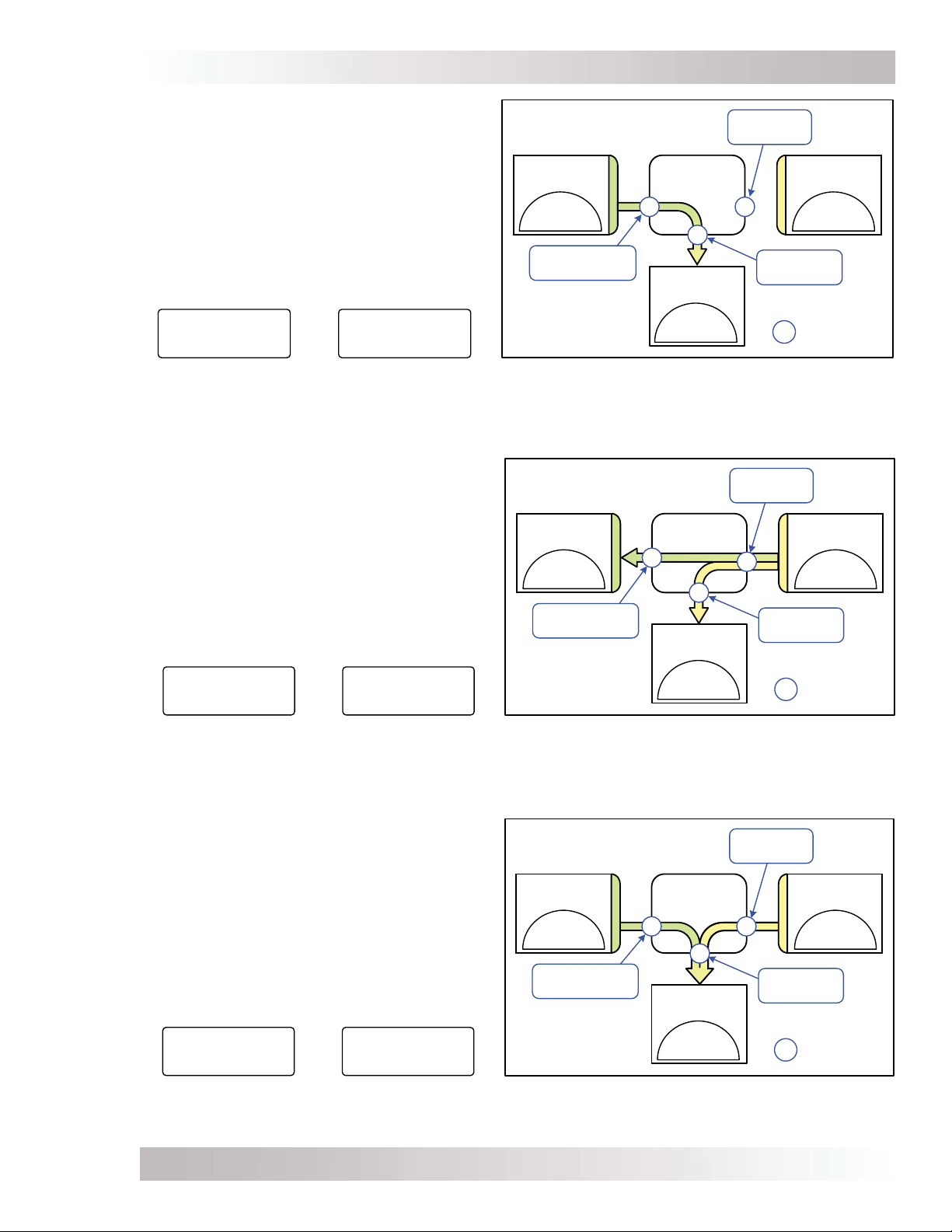
Setup
INVERT MODE
Current from the battery is used by the inverter
to power the inverter’s AC loads.
Example below:
Current to inverter input (AC Input)
= 0 Amps AC
Current from battery (Inv/Chg Amps)
= -10 Amps AC
Current to power the AC loads (AC Load)
= 10 Amps AC
02B AC Amps:
AC Load = 10 AAC
AC Input = 0 AAC
P1 Read AC METER
02C Inv/Chg Amps
(In/Out of Battery)
-10 Amps AC
P1 Read AC METER
Figure 3-6, Current Flow – Inverter Mode
STANDBY MODE
Current from the grid/generator to the inverter’s
AC input is used to power the inverter’s AC loads
and to charge the battery.
Example below:
Current to inverter input (AC Input)
= 20 Amps AC
Current to power the AC loads (AC Load)
= 10 Amps AC
Current to charge battery (Inv/Chg Amps)
= 10 Amps AC
02B AC Amps:
AC Load = 10 AAC
AC Input = 20 AAC
P1 Read AC METER
02C Inv/Chg Amps
(In/Out of Battery)
10 Amps AC
P1 Read AC METER
DC CURRENT
(BATTERY)
-120ADC
.FROM BATT
Inv/Chg Amps=
-10 Amps AC
DC CURRENT
(BATTERY)
120ADC
TO BATT
Inv/Chg Amps=
10 Amps AC
MAGNUM
INVERTER
INVERTER
AC LOADS
10AAC
TO LOADS
MAGNUM
INVERTER
A
INVERTER
AC LOADS
10AAC.
TO LOADS.
A
A
AC Input =
0 Amps AC
AC CURRENT
(GRID/GEN)
AA
AC Load =
10 Amps AC
A
AC Input =
20 Amps AC
AC CURRENT
(GRID/GEN)
A
AC Load =
10 Amps AC
A
0AAC
FROM GRID
Inverter
=
Amp meters
-20AAC.
FROM GRID
Inverter
=
Amp meters
Figure 3-7, Current Flow – Standby Mode
LOAD SUPPORT MODE
(MSH Series Only)
The MSH Series uses current from the battery to
assist in powering the inverter’s AC loads and to
reduce the current from the grid/generator.
Example below:
Current to inverter input (AC Input)
= 10 Amps AC
Current to power the AC loads (AC Load)
= 20 Amps AC
Current from battery (Inv/Chg Amps)
= -10 Amps AC
02B AC Amps:
AC Load = 20 AAC
AC Input = 10 AAC
P1 Read AC METER
02C Inv/Chg Amps
(In/Out of Battery)
-10 Amps AC
P1 Read AC METER
Figure 3-8, Current Flow – Load Support Mode
© 2014 Magnum Energy, Inc.
DC CURRENT
(BATTERY)
-120ADC
FROM BATT
Inv/Chg Amps=
-10 Amps AC
MSH SERIES
INVERTER
A
INVERTER
AC LOADS
20AAC.
TO LOADS.
AC Input =
10 Amps AC
AC CURRENT
(GRID/GEN)
AA
AC Load =
20 Amps AC
A
-10AAC.
FROM GRID
Inverter
=
Amp meters
Page 21
Page 30
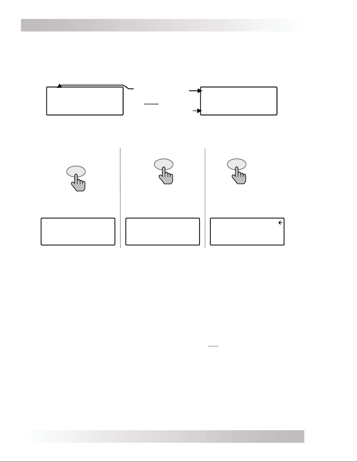
Setup
3.3.3.1 Additional METER Menus for Port-connected Inverters
The METER button also provides meter displays for each active port-connected inverter (or
accessory) in your system. These displays are similar to those listed in Section 3.3.3, but the
displayed information is specifi c to the particular inverter and/or model (Figures 3-9 & 3-10 below).
All Ports Inverter Single Port
02C System AC Amps:
AC Load = 20 AAC
AC Input = 30 AAC
ALL Read AC METER
Figure 3-9, ALL Ports vs Port-specifi c METER Menus
To access
System Home screen:
METER
Press &
hold 3
secs
Inverting
25.6VDC 20ADC
ALL System Home
Note that menu
prefix & title
may differ
Identifies Port#
PORT
Press the PORT
button until the
device’s Port
screen displays
MS4024PAE Master
Inverting
25.6VDC 20ADC
P1 INV Home
02B AC Amps:
AC Load = 20 AAC
AC Input = 30 AAC
P1 Read AC METER
METER
Press to
view meters
01 DC Meters
02 AC Meters
03 Timers
P1 Select INV METER
Figure 3-10, Accessing Port-specifi c METER Menus
Port-specifi c Inverter METER Menus
The following METER menus are available for each port-connected inverter. Information is for the
specifi c selected inverter (versus ALL-Port meters that are system meter information).
METER: 01 DC Meters
• 01A DC Volts to Inverter: See information for 01A DC Volts to INV menu in previous section.
• 01B Inv/Chg DC Amps (In/Out of Battery): See information for 01B Inv/Chg DC Amps
menu in previous section.
METER: 02 AC Meters
• 02A AC Output: See information for 02A AC Output Volts and 02B AC Output Hz menus in
previous section.
• 02B AC Amps: See information for 02C System AC Amps menu in previous section.
• 02C Inv/Chg Amps (In/Out of Battery): See information for 02D Inv/Chg Sys Amps (In/
Out of Battery) menu in previous section.
• 02D AC Input Volts: See information for 02H Input Volts AC1 menu in previous section.
Note: For a MSH-RE model inverters only, this menu also displays input volts for the AC2
source as well (02I Input Volts AC2). Refer to menu maps in Figure 4-2.
METER: 03 Timers
• 03A Charge Time: See information for 03A Charge Time menu in previous section.
03B Days Since: See information for 03B Days Since menu in previous section.
© 2014 Magnum Energy, Inc.Page 22
Page 31

Setup
3.3.4 SETUP Button and Menus
Pressing the SETUP button provides access to the menu items and settings that enable you to
confi gure the router display, the inverter/charger, a ME-AGS-N, and a ME-BMK. Review each menu
item to determine if you need to adjust any settings to meet your system requirements.
Info: The fi rst screen that may appear when the SETUP button is pushed is a password
screen. If the PIN has been set under the TECH button’s 05 SETUP PIN menu, the fi rst
screen is the Set SETUP PIN menu. The proper PIN must now be entered in order to
access the SETUP menus. After fi ve minutes from the last button push, the display
automatically returns to the System Home screen and the PIN must be reentered in
order to access the SETUP menus. Refer to the TECH button’s SETUP PIN menu to set
or change the PIN number.
Rotate to desired selection:
Top line shows menu
SETUP
Press
01 System Setup
02 Inverter Setup
03 Charger Setup
ALL Select SETUP
01 System Setup
Press to
select
02B Low Battery Cut
Out (LBCO) Volts =
20.0 Volts
ALL View INV SETUP
Bottom line shows menu
(Ex: Inverter Setup menu)
02 Inverter Setup
03 Charger Setup
04 AGS Setup
05 BMK Setup
06 RC Setup
Figure 3-11, SETUP Button
SETUP: 01 System Setup
The following menus are used to set up the router clock and screen.
• 01A System Clock: The router contains a real time clock that must be set for proper operation
of some features. These features are: the SETUP button’s 02C AC In – Time, 04B Gen Run
Time, 04G Gen Quiet Time, 04H Gen Exercise menus, and the TECH button’s 04 Fault History
menu items.
**IMPORTANT**
It is very important that you set the time clock as it is a critical piece in effectively addressing
fault issues, as well as for the proper start/stop functions of your AGS device, if installed.
Info: The clock obtains power from the inverter and will reset if the router is disconnected
from the inverter.
To Set the Current Time
From the Set System Clock menu:
1. Rotate the SELECT knob to the hour of day, and then press SELECT.
2. Rotate the SELECT knob to the correct minute setting, and then press SELECT.
3. Rotate the SELECT knob to the appropriate AM or PM setting, and then press SELECT.
• 01B Screen Setup: This setting adjusts the contrast and brightness of the LCD screen to
accommodate the current lighting conditions and viewing angle.
Default settings: Contrast = 100%, Brightness = 50%
Range: 0-100%
© 2014 Magnum Energy, Inc.
Page 23
Page 32

Setup
Info: If DC power is lost to the router, the 01B Screen Setup setting defaults back to
the default settings (Contrast = 100%, Brightness = 50%).
• 01C Power Save: This setting turns off the Power Save™ feature, or you can select a duration
of time (from 1 to 60 minutes) that determines when the display goes into Power Save mode.
This setting also allows the Port LEDs to be turned “OFF,” or set to “Auto” mode. If you want
the Port LEDs to always be off, you will need to set the Port LEDs to OFF. In Auto mode, the
Port LEDs automatically blink whenever a device is communicating to a router port.
Default settings: PowerSave [Min] = OFF, Port LEDs = Auto
Range: PowerSave = OFF, 1-60 min; Port LEDs = Auto, OFF
What is the Power Save feature? This feature turns off the router’s LCD backlight and LEDs to
conserve energy. The router enters Power Save mode if there hasn’t been a button press or fault
message for a set period of time (per minutes setting). When in Power Save mode, the router’s
LCD backlight and LEDs can be reactivated by pressing any button. If you have a fault during Power
Save mode, the LCD backlight and FAULT LED come on and stay on as long as the fault is present.
Info: If you want the LCD backlight and LEDs to always be on (while communicating),
the PowerSave [Min] setting must be OFF and the PORT LEDs set to Auto.
Info: Pressing the SELECT knob causes the router to exit Power Save mode. However,
rotating the SELECT knob will not cause the router to come out of Power Save mode.
• 01D Temp Display: This menu item selects whether to display temperatures in Fahrenheit
or Celsius. Once you select either Fahrenheit or Celsius, the following menu items are affected
by this selection: the METER button’s 04D AGS Temp menu, the SETUP button’s 04E Gen Run
Temp menu, and the TECH button’s 01 INV Temperatures menu.
Default setting: Fahrenheit
Range: Fahrenheit, Celsius
• 01E Viewing Ports: The Viewing Ports menu item sets the device “home” screen (i.e., Port
Home) to either automatically scroll through each active/connected port, or requires you to
manually select each port. Selecting and adjusting the seconds enables the Auto Scroll feature
and allows you to determine how long each active device home screen (under the PORT button)
is displayed before it automatically scrolls to the next active “home” screen.
Default setting: Auto Scroll [secs] = OFF
Range: Auto Scroll = OFF, 1-60 secs
Info: Once the Auto Scroll feature is enabled, the active “home” screen menus under
the PORT button begin auto-scrolling after one minute of inactivity (i.e., no button push
or pressing the SELECT knob).
Info: Rotating the SELECT knob pauses the display’s auto-scrolling. Once the SELECT
knob is no longer rotated, auto-scrolling resumes—it does not require another minute
of inactivity to resume auto-scrolling.
• 01F RTR Aux Relay: The Aux Relay becomes a battery voltage-controlled relay when Auto
VDC or Auto VDC (BTS Comp) is selected from the CTRL/04 RTR Aux Relay menu. It can be
programmed to open or close on DC volts with an adjustable delay using the following settings.
◊ Open Volts – The battery voltage trip point at which the Aux Relay contacts will open.
This setting can be below or above the Close Volts setting, depending on if you want the Aux
Relay to be active low or active high.
◊ Close Volts – The battery voltage trip point at which the Aux Relay contacts will close.
This setting can be below or above the Open Volts setting, depending on if you want the Aux
Relay to be active low or active high.
Default settings: Open = 10.0 VDC (12v), 20.0 VDC (24v), 40.0 VDC (48v);
Close = 14.0 VDC (12v), 28.0 VDC (24v), 56.0 VDC (48v)
Range: Open & Close Volts = 8.0-17.0 VDC (12v), 16.0-34.0 VDC (24v), 32.0-68.0 VDC (48v)
© 2014 Magnum Energy, Inc.Page 24
Page 33

Setup
Example – Active Low: Set Close Volts below Open Volts voltage. If the Close Volts voltage is
set at 24.0 VDC and the Open Volts voltage is set at 29.0 VDC, the relay would close when the
battery voltage dropped to 24.0 VDC and open when the battery voltage rises to 29.0 VDC. This
configuration might be used to control a battery exhaust fan or as a simple PV charge controller.
Example – Active High: Set Close Volts above the Open Volts voltage. If the Open Volts voltage
is set at 24.0 VDC and the Close Volts voltage is set at 29.0 VDC, the relay would open when the
battery voltage dropped to 24.0 VDC and close when the battery voltage rises to 29.0 VDC. This
configuration might be used to control a low voltage disconnect circuit for a DC load.
◊ Open Delay – Use to delay the opening of the Aux Relay contact once the battery voltage
trip point has been reached. This sets a hysteresis so the Aux Relay does not cycle unnecessarily.
◊ Close Delay – Use to delay the close of the Aux Relay contact once the battery voltage trip
point has been reached. This sets a hysteresis so the Aux Relay does not cycle unnecessarily.
Default settings: Open & Close Delay = 10 secs
Range: Open & Close Delay = 0-127 secs, then 1-127 mins
Info: The Close/Open Volts and Open/Close Delay settings are only available if the Auto
VDC or Auto VDC (BTS Comp) options have been selected (CTRL: 04 RTR Aux Relay).
Example: The Aux Relay is set to Auto VDC. The Open Volts setting is 29.0 VDC and the Close
Volts setting is 24.0 VDC, and the Open Delay and Close Delay settings are set to 10 seconds.
When the battery voltage reaches 24.0 VDC, after a 10-second delay the Aux Relay will close and
the LED will illuminate. When the battery voltage reaches 29.0 VDC, after a 10-second delay the
Aux Relay will open and the Aux Relay LED indicator will turn off.
• 01G Aux Relay SOC: The Aux Relay becomes a battery SOC-controlled relay when Auto SOC
is selected from the CTRL/04 RTR Aux Relay menu. It can be programmed to open or close on
the battery’s State of Charge using the following settings.
Note: Requires a ME-BMK battery monitor to provide SOC values to the inverter.
◊ Open – The battery SOC trip point at which the Aux Relay contacts will open. This setting
can be below or above the Close SOC setting, depending on if you want the Aux Relay to be
active low (i.e., set Open below Close) or active high (i.e., set Open above Close).
◊ Close – The battery SOC trip point at which the Aux Relay contacts will close. This setting
can be below or above the Open SOC setting, depending on if you want the Aux Relay to be
active low (i.e., set Open below Close) or active high (i.e., set Open above Close).
Default settings: Open = 50%; Close = 100%
Range: Open & Close = 20-100%
Info: The METER: 05 BMK Meters/05A BMK SOC meter must have a valid SOC number
for the Aux Relay to determine when to start and stop based on the battery SOC. Under
the METER/05 BMK Meters/05A BMK SOC menu, Think’n, No Comm, or any BMK fault
(i.e., Factory Fault, Power-up Fault, or Unknown Fault ##) are not valid SOC numbers.
SETUP: 02 Inverter Setup
The following menus (02A – 02D) are used to set up only the functions related to the Inverting
mode of the inverter/charger.
• 02A Search Watts: Allows turning off the Search Watts feature or adjusting the power level
to determine when the inverter leaves Search mode. If not needed, select Sensitivity = OFF.
When search is turned off, the inverter continuously provides full AC voltage to the loads.
Default setting: Sensitivity = 5 Watts
Range: OFF, 5-50 Watts
Info: When the Search Watts feature is active, “Searching” appears on the top line of
the LCD display and the green INV LED will fl ash.
© 2014 Magnum Energy, Inc.
Page 25
Page 34

Setup
What is the Search Watts feature? This feature is used to help save battery power by reducing
the inverter’s output to search pulses when there is no detectable load. If a load greater than the
wattage level setting turns on while the inverter is ‘searching’, the inverter will start ‘inverting’ to
provide full voltage on its output.
Should I use the Search Watts feature? If the inverter can spend a great deal of time searching
(to reduce the power drain on your batteries) and you can tolerate small loads (less than 5 watts)
being off, then the Search mode feature should be used. However, if some small loads (e.g., digital
clocks, satellite receivers, answering machines, etc.,) are required to be on, then this feature
should be turned off (Sensitivity = OFF).
Where should I set Search Watts? The Search Watts setting should be adjusted to the same
power level (or the next lower setting) of the smallest load that you plan to run. If you don’t know
the wattage of the smallest load, turn the switch for the load on and decrease the Search Watts
setting until the load comes on and stays on.
Info: Even with Search Watts on, some connected equipment— even if turned off—may
draw enough current to keep the inverter in the Inverting mode (i.e., not “searching”).
• 02B Low Battery Cut Out: The Low Battery Cut Out (LBCO) menu sets the DC voltage level
that turns off the inverter. This helps protect the batteries from over-discharge damage. If the
battery voltage drops below the LBCO set-point continuously for more than 1 minute, the FAULT
LED will come on, the inverter will turn off, and the display will show a ‘Low Battery’ status.
If the battery voltage falls below 8.5 volts (12-volt models), 17.0 volts (24-volt models) or
34.0 (48-volt models), the FAULT LED and ‘Low Battery’ status indications will be immediate.
Default settings: LBCO Volts = 10.0 VDC (12v), 20.0 VDC (24v), 40.0 VDC (48v)
Ranges: 9.0-12.2 VDC (12v), 18.0-24.4 VDC (24v), 36.0-48.8 VDC (48v)
Where should I set the LBCO setting? If your goal is to not discharge your batteries more
than 20%*, then set the LBCO from 11.5 to 12.2 VDC (12-volt models), 23.0 to 24.4 VDC (24-
volt models), or 46.0 to 48.8 (48-volt models). In some applications, such as those installed in
an off-grid home or when doing a lot of RV dry-camping, you may want to cycle down to 50%*
by setting the LBCO from 10.0-11.4 VDC (12-volt models), 20.0-22.8 VDC (24-volt models) or
40.0-45.6 VDC (48-volt models). In extreme circumstances, you have the ability to discharge the
batteries to 80%* by setting the LBCO to 9.0-9.5 VDC (12-volt models), 18.0-19.0 VDC (24-volt
models), or 36.0-38.0 VDC (48-volt models) before recharging.
* These are rough estimates. For accurate battery monitoring, use the ME-BMK battery monitor.
Info: The higher the LBCO setting, the less the inverter discharges the batteries; which
allows the batteries to have a longer life. The down side to a higher LBCO setting is that
you need to charge more often to prevent the inverter from shutting off in Fault mode.
**IMPORTANT**
1. To use the AC In Control features (AC In – Time, AC In – Volts DC, and AC In – SOC), the AC
source must always be connected and available for use at the inverter’s AC input—such as
utility power. There is no benefi t from using the AC In feature if using a generator, because
the generator power may not be available when the AC In feature becomes activated.
2. When an AC In feature (AC In – Time, AC In – Volts DC, or AC In – SOC) is selected, that
feature is active whether or not there is any AC power on the inverter’s input. If no AC
power is available, the inverter continues in Inverter mode. However, if AC power becomes
available on the inverter’s input after the connect setting (Time, VDC, or SOC) has been
reached, the inverter continues to allow the incoming AC power to be connected and used
until the disconnect setting is reached.
3. When using a dual source inverter/charger such as the MSH4024RE, the AC In features
only work with the GRID IN (AC1) input.
© 2014 Magnum Energy, Inc.Page 26
Page 35

Setup
• 02C AC In – Time: This feature allows you to connect to the local power utility at a
predetermined time of day. When the current time falls within the set times, the inverter/
charger connects to the AC that is connected to the AC input terminals. Once outside the set
times, the inverter/charger disconnects from the AC source.
◊ Connect – Determines what time each day the inverter/charger allows the incoming AC
to connect and transfer the loads from the inverter’s battery power to the utility grid.
Default setting: 6:00AM
Range: 12:00AM-11:45PM (15 minute increments)
◊ Disconnect – Determines what time each day the inverter/charger disconnects any incoming
AC that is connected, and resumes powering the AC loads from the inverter’s battery power.
Default setting: 6:00PM
Range: 12:00AM-11:45PM (15 minute increments)
What is the AC In – Time feature? This feature allows the incoming AC to connect to the
inverter/charger and charge the batteries only during the time of day as set in the 02C AC In –
Time menu item. Even if AC is present on the AC input terminals of the inverter/charger, it can
only connect during those times previously set. The most common use of AC In – Time is when
your local utility company offers peak rate savings (or “time of day billing”). The utility company
offers the peak rate savings with a lower rate per kWh (kilo Watt hour)—usually available at night
when there is less demand on the local utility grid. The AC In – Time feature may save you money
by only connecting to the utility when rates are the least expensive.
Where should I set AC In – Time? Check with your local utility company or installer and see
if they offer lower rates at particular times of the day. If a lower rate is offered, try setting your
connect/disconnect times to coincide with the utility companies lower rates to save you money.
• 02D AC In – Volts DC: Based on the inverter’s battery voltage, the AC In – Volts DC settings
determine when the inverter automatically connects and disconnects the incoming utility power.
◊ Connect – This setting determines at what DC voltage the inverter/charger connects to
incoming AC and transfers the loads from the inverter battery power to the utility grid. The
transfer occurs only if the battery voltage remains below this setting for 10 seconds.
Default settings: 11.0 VDC (12v), 22.0 VDC (24v), 44.0 VDC (48v)
Ranges: 9.0-15.9 VDC (12v), 18.0-31.8 VDC (24v), 36.0-63.6 VDC (48v)
◊ Disconnect – Once the inverter has connected to the incoming AC—based on the VDC
Connect setting—this setting determines at what DC voltage the inverter/charger disconnects
from incoming AC and resumes powering the AC loads from the inverter’s battery power.
Default settings: 14.1 VDC (12v), 28.2 VDC (24v), 56.4 VDC (48v)
Ranges: 9.1-16.0 VDC (12v), 18.2-32.0 VDC (24v), 36.4-64.0 VDC (48v)
Info: The 02D AC In – Volts DC (Connect and Disconnect) settings are not temperature-
compensated.
Info: If you have a ME-BMK battery monitor, use the AC In – SOC feature instead
of the 02D AC In – Volts DC feature. The AC In – SOC feature takes temperature
compensation into account and is a more accurate way to identify when your battery is
discharged/charged—to determine when to transfer to/from utility power.
What is the AC In Volts DC feature? This feature allows the inverter system to automatically
switch between utility connected and standalone battery operation—based on the VDC voltage
(i.e., battery) to the inverter. When using this feature, the inverter loads are powered from the
battery—which is normally charged from an energy source such as solar, wind, and/or hydro. In
the event the energy source cannot keep the battery voltage from falling, once the battery voltage
drops to the Connect volts setting the inverter connects to the utility to continue powering the
loads connected to the inverter’s output (and to charge the battery). When the energy source
can again deliver enough power to raise the battery voltage to the Disconnect volts setting, the
inverter disconnects from the utility and again powers the inverter loads from the battery.
© 2014 Magnum Energy, Inc.
Page 27
Page 36

Setup
Where should I set AC In – Volts DC? Check with your battery manufacturer to determine the
correct settings for your batteries. Typically, battery manufacturers do not recommend discharging
the batteries below 50%, which when related to a voltage setting is approximately 12.0-12.2
VDC, 24.0-24.4 VDC and 48-48.8 VDC for 12, 24 and 48-volt batteries, respectively. In order to
protect the batteries from over-discharging, set the connect voltage setting to 12.2 VDC, 24.4
VDC, or 48.8 VDC, respectively.
Set the disconnect voltage setting higher than the absorb voltage setting in order to reduce cycling
of the system. A setting higher than the absorb voltage requires the energy source (e.g., solar,
wind, etc.,) to raise the DC voltage above the charger settings. This ensures the battery gets at
least an 80-85% charge (preferably 100%) before the AC is disconnected and the inverter resumes
powering from the batteries.
• 02E AC In – SOC
disconnects the incoming utility power based on the SOC of the inverter battery bank.
Note: Requires a ME-BMK battery monitor to provide SOC values to the inverter.
◊ Connect – This setting determines at what battery SOC% the inverter connects to incoming
utility power and transfers the loads from the inverter battery power to the utility grid.
Default setting: 80% SOC
Range: 20-99%
◊ Disconnect – Once the inverter has connected to the incoming AC—based on the SOC
Connect setting—this setting determines the battery SOC% at which the inverter disconnects
from incoming utility power and resumes powering the loads from the inverter’s battery power.
Default setting: 100% SOC
Range: 21-100%
:
This setting determines when the inverter automatically connects and
Info: The transfer to/from incoming AC occurs immediately when the Connect SOC or
Disconnect SOC setting is reached.
Info: A ME-BMK is required in order to use the 2E AC In – SOC setting. If this setting is
selected and there is no ME-BMK installed in the system, or if a valid SOC number is not
displayed under the METER/05 BMK Meters/05A SOC menu (i.e., Think’n, No Comm,
Pwr-up Fault and Factory Fault are not valid SOC numbers), then the inverter will not
connect to the incoming AC power.
What is the AC In – SOC feature? This feature allows the inverter system to automatically
switch between utility connected and standalone battery operation based on the inverter’s battery
SOC that is provided by the ME-BMK battery monitor. When using this feature, the inverter loads
are normally powered from the battery and a solar array (or other energy source such as wind,
and/or hydro). In the event the solar array cannot deliver enough power and the battery’s SOC
drops to the Connect SOC setting, the inverter connects to the utility to continue powering the
loads connected to the inverter’s output and to charge the battery. Once the solar array can
again deliver enough power to charge the battery to the Disconnect SOC setting, the inverter
disconnects from the utility and again powers the inverter loads from the battery.
Where should I set AC In – SOC? Check with your battery manufacturer to determine the correct
settings for your batteries. For the Connect SOC setting, most manufacturers do not recommend
discharging the batteries below 50% to maintain the life of the battery. For the Disconnect SOC
setting, set it to a value to get at least an 80-85% charge (preferably 100%) before the AC is
disconnected and the inverter resumes powering from the batteries.
Info: When using AC In – SOC, ensure the SETUP: 03D Absorb Done SOC setting is
higher than the Disconnect SOC setting, or the inverter may not disconnect from the
incoming AC because the battery may not be charged to a high enough SOC level to
meet the Disconnect SOC setting.
© 2014 Magnum Energy, Inc.Page 28
Page 37

Setup
Notes on using the AC In feature based on VDC or SOC:
1. The AC In –VDC and AC – In SOC features allow you to optimize the use of another energy
source (i.e., solar, wind, and/or hydro), and only allow the use of the utility power when the
energy source is not able to keep up with the load demands under normal conditions (e.g.,
cloudy day).
2. The energy source should be sized to meet the daily power requirements of the loads being
operated under normal conditions. Otherwise, the inverter would be connected to utility power
most of the time, resulting in excessive energy consumption from the utility.
3. The inverter system should not be confi gured for use in a utility back-up scenario, otherwise
the battery may be in a highly discharged state when grid power goes down—preventing the
critical loads from running during a power outage.
4. The incoming AC is normally disconnected from the inverter. The Connect setting (VDC or
SOC) must be reached before the inverter will allow the incoming AC to connect.
• 02F Inverter Always Power-Up When DC is Connected: Forces the inverter to turn on
when DC voltage to the inverter is applied. Allows the inverter to power up and provide AC
power automatically once the battery is connected to the inverter.
Default setting: NO
Range: YES, NO
What is the Always Power-Up feature? Normally, when DC power is connected to the inverter,
the user is required to press the inverter’s or the router’s power button to turn on the inverter.
If the Always Power-Up feature is activated by selecting “YES”, then whenever DC power is
connected, the inverter is automatically turned on and starts searching or inverting—depending
on the SETUP button’s 02 Inverter Setup/02A Search Watts setting. Once automatically turned
on, the power button on the inverter or router can be used to turn the inverter on or off.
Why use the Always Power-Up feature? Some people are familiar with Uninterruptable Power
Supplies (UPS) that power-up automatically when DC power is connected. The Always Power-Up
feature allows the inverter to power-on similar to an UPS.
• 02G Inverter Threshold to Start Parallel (or, the “parallel threshold”): This setting
is used for inverters in a parallel-stacked inverter system, and determines when the slave
inverters turn on as a result of the percentage of power being provided by the master inverter
Default setting: 60%
Range: OFF, 30%-90% (10% increments)
Info: Ensure the parallel threshold setting is not too high or the master inverter may
reach its full output capacity and overload before the slave inverters can turn on and
assist in powering the loads.
Info: The 02G Inverter Threshold to Start Parallel feature only works with the parallel
stacking inverter models (i.e., MS-PAE and MS-PE Series).
Info: When this setting is reached, all connected slave inverters turn on at the same
time to deliver maximum power to the loads. After running approximately 30 seconds
to stabilize the AC current, the slave inverter(s) that are not needed will shut down and
the units that are still inverting will share the AC current equally.
Example: There are 3 MS4024PAE units in parallel (Master, Slave 1, and Slave 2) with a total
capacity of 12kW—the parallel threshold default is set to 60%. The master inverter is running a
2000W load, which is below the 60% threshold (4000W x .6 = 2400W). A 1000W load is added
for a total system load of 3000W, exceeding the parallel threshold setting of 2400W. Slave 1 and
Slave 2 inverters turn on, delivering up to 12,000W total power. Within approximately 30 seconds,
the system shuts down Slave 2, and the Master and Slave 1 each run 1500W (sharing the 3000W
load equally between them). Now, if the 1000W load is turned off (reducing the total system load
to 2000W again), Slave 1 turns off and only the Master inverter will be running the 2000W load.
© 2014 Magnum Energy, Inc.
Page 29
Page 38

Setup
Should I use the Parallel Threshold feature? Depends on the application. Most applications
set a threshold level such that the connected slave inverters come on only when required to power
the loads. This reduces the power drain on the batteries because the slave inverters that are not
actively powering the loads are in standby. On the other hand, if you have a load larger than the
capacity of the master inverter and the startup current is needed very quickly, you may need to
turn the threshold setting to OFF. This ensures all the stacked inverters are always on to meet
the fast startup current requirements of this large load.
Where should I set the Parallel Threshold? Depends on typical AC loads and how much time
you want the master inverter to run (versus the slaves). If you want the master inverter to run
as much of the loads as possible before the slave(s) turn on, then set the threshold at a higher
setting. If you want the slave(s) to share more of the load, then set the threshold to a lower setting.
Example: Loads are typically under 4000W and you have a 3-inverter parallel system. You want
the Master to run loads up to 3000W before the slave inverters turn on. Set the parallel threshold
to 75% (4000W x .75 = 3000W). The Master inverter will now run any load up to 3000W before the
slave inverters turn on. In this scenario, if a 5000W load was turned on, the slave inverters would
turn on, and then Slave 2 would turn off, and the Master and Slave 1 would each run at 2500W.
SETUP: 03 Charger Setup
• 03A AC Input Amps: This setting ensures that the combined current draw from the battery
charger and the AC loads does not exceed the maximum input current that is available from
the incoming AC power. This setting is used to set that maximum input current level. Whenever
the incoming AC is connected and passing thru the inverter, the current from the incoming
AC used to power the AC loads and charge the batteries is monitored. If this current begins
to approach the AC Input Amps setting, the charger current is automatically reduced. This
ensures the AC loads have all the available current from the incoming AC power when needed.
If using a MSH-M or MSH-RE (Hybrid) inverter, the AC input settings also determine when
the battery current begins to operate in parallel with the incoming AC power to support the
inverter loads, known as Load Support. The Load Support feature uses additional power from
the inverter’s battery to run loads greater than what the incoming AC power can run alone,
and prioritizes the power of any external DC source (e.g., solar, wind, etc.,) over the incoming
AC power to run inverter loads. For more information, see the Load Support Mode section in
the MSH-M or MSH-RE Series Owner’s Manual.
Setting for all models except MSH4024RE:
◊ Set AC Input Amps
Default setting: 30 Amps
Range: 5-60 Amps
Settings for MSH4024RE:
◊ Set AC Input Amps (AC1 and AC2)
Default setting: AC1 = 30 Amps, AC2 = 20 Amps
Ranges: 5-60 Amps
CAUTION: Unless you have an MS Hybrid Series inverter/charger—which has the Load
Support feature—the AC Input Amps setting only limits the current to the battery, it
does not limit the current to the inverter loads. If the current from the loads on the
output of the inverter is greater than the circuit breaker rating on the incoming AC
source, you will experience nuisance tripping.
Where should I set AC Input Amps? This setting needs to be set differently depending on your
inverter/charger model—as described below:
ME, MS, and RD Series: These models connect to a single AC source and have two inputs (HOT
IN 1 and HOT IN 2), but the current is only monitored on HOT IN 1. On these models—when wired
as a dual-in confi guration or as a single-in confi guration with only the HOT IN 1 connected—the
AC Input Amps setting should be set to the size of the AC circuit breaker that feeds the HOT IN
1 input. On these models, when wired as a single-in confi guration with HOT IN 1 and HOT IN 2
jumped together, set the AC Input Amps setting to half (x½) the input breaker size—as half the
current will pass through HOT IN 1 and the other half through HOT IN 2 simultaneously.
© 2014 Magnum Energy, Inc.Page 30
Page 39

Setup
MS-AE and MS-PAE Series: These models connect to a single AC source and have two inputs
(HOT IN 1 & HOT IN 2), with the current monitored on both inputs at the same time. Since the
input is from a single AC source, both of the input currents are added, then divided in half to
determine the AC Input Amps setting. If the input breaker is a dual-pole (120/240 VAC input), set
the AC Input Amps setting to the value of only one of the breaker poles (i.e., 30A dual-pole = 30A
setting). If the input breaker is a single-pole (120 VAC input) and connected to only one input, set
the AC Input Amps setting to one-half the input breaker size (i.e., 30A single-pole = 15A setting).
MS-E, MS-PE, MSH-M and RD-E Series: These models connect to a single AC source and have one
input. On these models, set the AC Input Amps setting to match the input AC circuit breaker size.
MSH-RE Series: These models can connect to two AC sources and have two inputs (AC1 & AC2),
with the current monitored on each input separately. AC1 is set to the size of the utility breaker
feeding the AC1 input, and the AC2 is set to the size of the generator’s breaker feeding the AC2 input.
MM, MM-AE and MMS Series (and any export version of these models): These models do
not monitor current on the input, therefore cannot benefi t from the AC Input Amps setting or
feature. On these models, even though the AC Input Amps setting may display and allow selection/
adjustment, this setting will not do anything to reduce the battery charger current.
Info: If you are supplying two AC sources (utility and generator) to the inverter’s single
input through an AC transfer switch, adjust the AC Input Amps setting to the smaller AC
circuit breaker side of the two AC sources.
Info: The AC Input Amps setting is dependent on the stability of the AC source. If
using a generator, factors such as altitude and output voltage regulation may require
a lower setting than the generator’s circuit breaker size. For best performance, lower
the AC Input Amps setting to 1/3 of the generator’s rated capacity, and then while
the generator is heavily loaded, gradually increase the setting as high as possible; but
ensure the voltage level stays above the 03B Low VAC Dropout setting.
• 03B Low VAC Dropout: Selects the minimum AC voltage that must be present on the input
before the inverter/charger connects to the AC input and switches from Inverter mode to
Standby mode. This setting also determines the lowest AC voltage that is allowed before the
charger disengages and the inverter (if enabled) resumes powering the AC loads from the
inverter’s battery power—to protect AC loads during utility outages.
Example: If the Low VAC Dropout setting is 60 VAC, then the AC input voltage must be above
60 volts before the inverter connects and switches from Inverter mode to Standby mode. Once
the AC is connected, the AC voltage must drop below 60 VAC to switch back to Inverter mode.
Settings for all models except MSH4024RE:
◊ Set Low VAC Dropout (AC1 only) – Sets at what AC voltage—from the HOT IN 1 to NEUT
IN 1 terminals—the inverter/charger will connect to or disengage from the incoming AC.
Default setting: 80 VAC (150 VAC for export models)
Range: 60-100 VAC, UPS Mode (110-190 VAC, UPS Mode for export models)
Settings for MSH4024RE models:
Info: The MSH4024RE is a dual input source inverter/charger having two independent
AC source inputs (AC1/GRID and AC2/GEN) with independent VAC dropout settings for
each input. The Set Low VAC Dropout screen only displays both the AC1 and AC2 fi elds
if the router is connected to the MSH4024RE.
◊ Set Low VAC Dropout (AC1 and AC2) – The AC1 setting determines at what AC voltage—
from the AC1 to NEUT terminals—the inverter/charger will connect to or disengage from the
incoming AC. The AC2 setting determines at what AC voltage—from the AC2 to NEUT terminals—
the inverter/charger will connect to or disengage from the incoming AC.
Default setting: AC1=80 VAC, AC2=70 VAC
Range: 60-100 VAC, UPS Mode*
* – Do not use UPS Mode as the AC2 setting if using a generator as your AC source.
© 2014 Magnum Energy, Inc.
Page 31
Page 40

Setup
Where do I set my VAC Dropout? It depends on the application and what you are using as
the AC source. The settings not only look at the incoming voltage level to determine when to
transfer, but also determine how quickly the charger disconnects and starts inverting based of
the fl uctuations of the incoming AC voltage.
Dropout = 60 VAC to 100VAC (Export inverter models: Dropout = 110 VAC to 190 VAC)
– Use a Low VAC Dropout setting from 60 VAC to 100 VAC (export models use a dropout from
110 VAC to 190 VAC) when the AC source may have fl uctuations in RMS voltage. These settings
attempt to prevent the charger from disengaging unnecessarily due to poor quality voltage, and
are highly recommended if using a generator for charging. The transfer time from Standby mode
to Inverter mode is >16 milliseconds when using these settings.
Dropout = UPS Mode – Use the UPS Mode setting when the AC source is well regulated above
105 VAC (200 VAC for export inverter models), and the inverter loads are sensitive to voltage
fl uctuations. This setting is intolerant of voltage fl uctuations and will provide a quick transfer. The
transfer time from Standby mode to Inverter mode is ≤16 milliseconds when using this setting.
Info: If you get nuisance AC disconnects, either change the setting to 100 VAC or less
(export models 190 VAC or less), or obtain a better voltage-regulated AC source.
• 03C Battery Type: This setting selects the battery type, which determines the battery charge
profi le and ensures the batteries are receiving the proper charge voltage. The charge voltage
settings are fi xed when using the GEL, Flooded, AGM1, or AGM2 selections, but can be adjusted
if using the CC/CV or Custom selections.
Default setting: Flooded
Range: AGM1, AGM2, Flooded, GEL, CC/CV, Custom
◊ Set Battery Type (GEL, Flooded, AGM1, or AGM2) – When the battery type selection is
GEL (for Gel batteries), Flooded (for liquid lead acid batteries), AGM1 (for Lifeline AGM batteries),
or AGM2 (for East Penn/Deka/Discover/Trojan AGM batteries), the charge voltage level for the
Absorption, Float, and EQ charge modes are fi xed and shown in Table 3-1—depending on the
battery type selected and the nominal inverter battery voltage.
Info: The voltage settings shown in Table 3-1 are based on the Battery Temperature
Sensor (BTS) at a temperature of 77° F (25° C), or not connected. If the BTS is
connected, the actual charge voltage will increase if the temperature around the BTS
is below 77° F (25° C), and decrease if higher than 77° F (25° C). This ensures the
batteries receive the correct charge voltage regardless of temperature.
Table 3-1, Battery Type to Charge Voltages (Fixed Voltage)
Battery
Type
Inverter
Voltage
Absorption
Voltage
Float
Voltage
Equalization
Voltage
12 VDC 14.1 VDC 13.6 VDC 14.1 VDC
GEL
24 VDC 28.2 VDC 27.2 VDC 28.2 VDC
48 VDC 56.4 VDC 54.4 VDC 56.4 VDC
12 VDC 14.6 VDC 13.4 VDC 15.5 VDC
Flooded
24 VDC 29.2 VDC 26.8 VDC 31.0 VDC
48 VDC 58.4 VDC 53.6 VDC 62.0 VDC
12 VDC 14.3 VDC 13.1 VDC 15.5 VDC
AGM1
2
24 VDC 28.6 VDC 26.2 VDC 31.0 VDC
48 VDC 57.2 VDC 52.4 VDC 62.0 VDC
12 VDC 14.5 VDC 13.5 VDC 14.5 VDC
AGM2
3
24 VDC 29.0 VDC 27.0 VDC 29.0 VDC
48 VDC 58.0 VDC 54.0 VDC 58.0 VDC
Note¹: Voltage same as absorption voltage—to prevent equalization.
Note²: Charge voltages for Concord (Lifeline Series) AGM batteries.
Note³: Charge voltages for East Penn, Deka, Discover and Trojan AGM batteries.
© 2014 Magnum Energy, Inc.Page 32
1
1
1
1
1
1
Page 41

Setup
◊ Set Battery Type (CC/CV) –
rent/Constant Voltage) charging cycle with an adjustable charge voltage and output current.
Note: CC/CV settings only display if CC/CV has been selected from the 03 Battery Type menu.
Info: If CV/CC has been selected from the 03C Battery Type menu, the following
menus are no longer accessible and display “CC/CV Controlled” when selected: 03D
Absorb Done, 03E Max Charge, 03F Final Charge, 03G Days to remind when to EQ. This
is to prevent charging confl icts that could occur while in the CC/CV profi le.
CAUTION: Whenever the CC/CV battery type is selected, some settings—within menus
that are no longer accessible—are internally linked to the CC/CV settings and can be
automatically changed. Because settings can be automatically changed once CC/CV has
been selected, if a different battery type is selected, then all charge settings must be
reviewed to ensure they are correct for the new battery type selection.
□ Max Chg Amps – Sets the maximum amperage allowed to charge the batteries during
the CC/CV charge cycle. This setting is provided to limit the charge current to the battery
bank, which helps prevent battery overheating caused by charging at too high a charge rate.
Default: Max Charge Amps = 200A
Range: 20 – 990 ADC
□ CV Chg Volts – Sets the voltage level at which the charger will hold the batteries during
the Constant Voltage cycle.
Default: CV Chg Volts = 13.8 VDC (12v), 27.6 VDC (24v), 55.2 VDC (48v)
Range: OFF, 12.0-16.0 VDC (12v), 24.0-32.0 VDC (24v), 48.0-64.0 VDC (48v)
Info: If the BMK (Battery Monitor Kit) is connected, the DC amps value determined by
the BMK (under METER: 05C DC Amps-BMK) will be used by the Max Chg Amps setting
instead of the inverter’s DC calculated current (shown under METER: 01B Inv/Chg DC
Amps)—as it is more accurate (+/ – .1 ADC).
CV Charge Done Time, CV Charge Done Amps, or Hold CV Charge Volts selections:
These selections determine when the second stage of charging (Constant Voltage) is fi nished.
If using the CV Charge Done Time or CV Charge Done Amps selections, once the constant voltage
charge cycle is fi nished, it transitions to a Silent charge stage. During the Silent charge mode,
charging is automatically stopped, but battery voltage is still monitored. The charger remains
“Silent” until the battery voltage drops to the Set DC Volts to Recharge setting, at which time
the charger will start another Constant Current/Constant Voltage charge cycle (see Figure 3-12).
The Hold CV Chg Volts selection holds the battery in the constant voltage charge cycle voltage
at the CV Chg Volts setting indefi nitely (see Figure 3-13).
Default: CV Charge Done Time
□ CV Chg Done Time – The CV Charge Done Time selection is used when a specifi c time
is selected to be the best solution for determining when the batteries are fully charged and
the Constant Voltage stage needs to end.
* Set CV Chg Done Time – This setting determines how long the charger will hold
the battery voltage at the CV Chg Volts setting—based on a set time period. When using
time, the battery bank size will typically determine the length of the CV Charge Done Time
setting. The larger the battery bank, the longer the time needed to ensure a full charge to
the batteries. The charger transitions to the Silent charge mode after the battery voltage has
been at the CV Chg Volts setting for the selected time. Refer to Table 3-2 to assist you in
selecting the CV Charge Done Time setting based on the AHr capacity of your battery bank.
Note: After choosing the Set CV Charge Done Time, the Set Max CC/CV Charge Time and
Set DC Volts to Recharge settings must be determined.
Default: Time = 2.0 Hrs
Range: 0.1-25.5 Hrs
□ CV Chg Done Amps – The CV Charge Done Amps setting is used when the DC amperage
supplied to the batteries (i.e., done amps) determines when the batteries are fully charged
and the Constant Voltage stage needs to end.
The CC/CV selection provides a 2-stage (Constant Cur-
© 2014 Magnum Energy, Inc.
Page 33
Page 42

Setup
Constant
Current
Max Charge
Amps
CURRENT & VOLTAGE
Current
Voltage
Constant
Voltage
CV Charge
Volts
CV Charge Done
(= Time or Amps)
Silent
Recharge
Volts
(restarts
Constant
Current
charge)
Constant
Current
TIME
Figure 3-12, CV Charge Done Time/Amps Charge Stages
* Set CV Charge Done Amps – This setting determines how long the charger will
hold the battery voltage at the CV Chg Volts setting—based on a minimum current setting
(i.e. done amps). During the Constant Voltage charge mode, as the battery charges, the
current from the charger slowly decreases. When this current decreases below the Set CV
Charge Done Amps setting, the charger transitions to the Silent charge stage. Most battery
manufacturers use a specifi c formula to determine the done amps that indicate a full charge
for their particular type of battery. The formula used by most manufacturers to absorb the
batteries is C/20, where C=Battery Bank’s Total Amp Hours. Basically, they take approximately
5% of the total battery bank size, and consider the battery totally charged when the charger’s
done amps drops to this level. Continuing to charge past this level may possibly overcharge
the batteries. Check with your battery manufacturer to fi nd out what the correct return amp
settings are for your batteries. Note: After choosing the Set CV Charge Done Amps selection,
the Set Max CC/CV Charge Time and Set DC Volts to Recharge settings must be determined.
Default: Amps = 20 ADC
Range: 0-250 ADC
Info: It is highly suggested that you install a battery monitor if the CV Charge Done
Amps setting is used. If a battery monitor is not installed, the CV Charge Done Amps
setting relies on the METER menu’s 01B Inv/Chg DC Amps value to determine when
to transfer out of the Constant Voltage charge mode. When a battery monitor kit (MEBMK/ME-BMK-NS) is installed, the CV Charge Done Amps setting relies on the METER
menu’s 05C DC Amps-BMK value to determine when to transfer out of the Constant
Voltage charge mode. This is the most accurate DC amperage measurement. The DC
amps reading from the battery monitor is accurate to +/ – .1 ADC.
Info: Setting the CV Charge Done Amps value to 0 (zero) will keep the charger in the
Constant Voltage charge mode until the Set Max CC/CV Time setting (under SETUP:
03C Battery Type/CC/CV) is reached.
Info: When using the CV Charge Done Amps setting, the charger will stay in the
Constant Voltage charge mode for a minimum of two minutes—even if the Done Amps
current is below the CV Charge Done Amps setting.
Info: If DC loads are connected directly to the batteries, it is not recommended that
you use the CV Charge Done Amps setting. DC loads cause the charger to increase the
amperage delivered to the battery bank in order to charge the batteries and to run the
DC loads. This scenario could result in overcharging the batteries since the done amps
reading will be skewed by the DC loads.
© 2014 Magnum Energy, Inc.Page 34
Page 43

Setup
ο Set Max CC/CV Time – This setting is a safety feature that ensures abnormal
conditions do not cause the charger to hold batteries at a high voltage for a prolonged period
of time. This menu sets a maximum time the charger is allowed to operate in either the
Constant Current or Constant Voltage charge modes. If the charger reaches the maximum
charge time setting, it will transition to the Silent charge stage. If using the OFF setting, the
charger will stay in the Constant Current and Constant Voltage charge modes indefi nitely.
Default: Time = 12.0 Hrs
Range: OFF, 0.1-25.5 Hrs
ο Set DC Volts to Recharge – This setting determines the DC voltage set-point to
which the batteries are allowed to fall—while the charger is in the Silent charge cycle—before
the charger restarts and recharges to the CV Chg Volts setting. This setting should be at
the lowest DC volts level that you want the batteries to fall before starting a new charge.
Default: DC Volts to Recharge = 12.0 (12v), 24.0 Volts (24v), 48.0 Volts (48v)
Range: 12.0-16.0 Volts (12v), 24.0-32.0 Volts (24v), 48.0-64.0 Volts (48v)
□ Hold CV Chg Volts – This setting holds the battery voltage at the CV Chg Volts setting.
This is for a system that requires a constant charge voltage to be present at all times.
Constant
Current
Max Charge
Amps
CURRENT & VOLTAGE
Current
Voltage
Constant Voltage
CV Charge
Volts
Hold CV Charge Volts
TIME
Figure 3-13, Hold CV Charge Volts CC/CV Charge Stages
◊ Set Battery Type (Custom) – This selection allows you to individually adjust the fl oat,
absorb, and equalization charge voltage settings and to set an equalization time for your
batteries. The following Custom battery settings display only if Custom has been selected from
the 03 Battery Type menu. Use these settings to determine the battery’s absorption, fl oat, and
equalization voltages, and the maximum amount of time spent equalizing.
CAUTION: To avoid damage during battery charging or equalization, consult the battery
manufacturer to ensure the best charge settings are used for your type of batteries.
□ Absorb Volts – Sets the level at which the charging voltage is held constant during an
Absorption cycle.
Default: 14.4 Volts (12v), 28.8 Volts (24v), 57.6 Volts (48v)
Range: 12.0-16.0 Volts (12v), 24.0-32.0 Volts (24v), 48.0-64.0 Volts (48v)
□ Float Volts – Sets the level at which the charging voltage is held constant during a Float
cycle.
Default: 13.2 Volts (12v), 26.4 Volts (24v), 52.8 Volts (48v)
Range: 12.0-16.0 Volts (12v), 24.0-32.0 Volts (24v), 48.0-64.0 Volts (48v)
© 2014 Magnum Energy, Inc.
Page 35
Page 44

Setup
□ EQ Volts – Sets the level at which the charging voltage is held constant during an
Equalization cycle. Note: Cannot be set lower than the Absorb Volts setting, or more than
2 volts (12v systems), 4 volts (24v systems), or 8 volts (48v systems) above the Absorb
Volts setting.
Default: 15.6 Volts (12v), 31.2 Volts (24v), 62.4 Volts (48v)
Range: 12.0-16.0 Volts (12v), 24.0-32.0 Volts, 48.0-64.0 Volts (48v)
□ EQ Time –
Default: 4.0 Hrs
Range: 0.1-25.5 Hrs
Info: The timer for the EQ Time setting (SETUP: 03C Battery Type/Custom menu):
a) Counts when EQ is enabled and the voltage is close to the EQ Volts setting (≥0.1v/12-
volt systems, ≥0.2v/24-volt systems, or ≥0.4v/48-volt systems).
b) Pauses when in Charger Standby.
c) Clears when EQ is fi nished, battery goes to Bulk/Absorb or Float, or EQ is stopped.
• 03D Absorb Done: This setting identifi es whether time, amps, or SOC are used to determine
when the Absorption charge stage is fi nished and transitions to the fi nal charge stage (see 03F
Final Charge Stage) afterwards. Absorption is the second stage of the battery charge process
that attempts to fully charge the batteries.
Note: If “CC/CV Controlled” displays on this menu’s screen, you will not be able to adjust the
settings as “CC/CV” has been selected as the battery type from the 03C Battery Type menu.
Default: Absorb Done Time
CAUTION: If the Absorption stage is short or terminated, the batteries may not receive
a full charge. In contrast, if the Absorption stage is too long the batteries may be
overcharged. Either scenario may lead to damage to the batteries. Contact your battery
manufacturer to ensure the best charge settings are used for your type of batteries.
◊ Set Absorb Done Time – Set Absorb Done Time is used when a specifi c time is determined
to be the best solution for ending the Absorption stage. When using time, the battery bank
size will typically determine the length of the Absorb Done Time setting. The larger the battery
bank, the longer the absorb time needed to ensure a full charge to the batteries. Taking specifi c
gravity readings of the batteries and adjusting the absorb time may be needed in order to
obtain the appropriate absorb time for your battery type and battery bank size. Use Table 3-2
to select the Absorb Done Time setting based on the amp-hr capacity of your battery bank.
Default setting: Absorb Done Time = 2.0 Hrs
Range: 0.1-25.5 Hrs
Sets the time (duration) the battery will charge at the EQ Volts setting.
Table 3-2, Battery Amp/Hrs Capacity to Suggested Absorb Time
Battery AmpHrs
Capacity
200 to 300 60 minutes 1310 to 1500 240 minutes
310 to 500 90 minutes 1510 to 1700 270 minutes
510 to 700 120 minutes 1710 to 1900 300 minutes
710 to 900 150 minutes 1910 to 2100 330 minutes
910 to 1100 180 minutes 2110 to 2300 360 minutes
1110 to 1300 210 minutes 2310 to 2500 390 minutes
Info: Range of the Absorb Done Time setting is dependent on the inverter’s compatibility
level. With a compatibility level of ≥4.0, the available range is 0.1-25.5 hrs. However,
if the compatibility level is less than 4.0, even though you can adjust the setting from
0.1-25.5 hours, the available range may not be recognized by the inverter, and causes
the charger to revert to the default setting of 2.0 hours. See Appendix B for more info.
Suggested Absorb
Time
Battery AmpHrs
Capacity
© 2014 Magnum Energy, Inc.Page 36
Suggested Absorb
Time
Page 45

Setup
◊ Set Absorb Done Amps – This setting is used when the DC amperage supplied to the
batteries determines when the batteries are fully charged. During Absorb Charge mode—as
the battery charges—the current required by the battery decreases. “Done amps” refers to
when the done amps decreases below the Absorb Done Amps setting continuously for two
minutes, the charger transfers from the Absorption charge cycle to the fi nal charge stage (see
03F Final Charge Stage). Most battery manufacturers use a specifi c formula to determine the
done amps that indicate a full charge for their particular type of battery. The formula used by
most manufacturers to absorb the batteries is C/20, where C=Battery Bank’s Total Amp Hours.
Basically, they take approximately 5% of the total battery bank size, and consider the battery
totally charged when the charger’s done amps drops to this level. Continuing to charge past
this level may possibly overcharge the batteries. Check with your battery manufacturer to fi nd
out what the correct return amp settings are for your batteries.
Default setting: Amps = 20 ADC
Range: 0-250 ADC
Info: Setting the Absorb Done Amps value to 0 (zero) will keep the charger in the
Absorption Charge mode until the 03E Max Charge: Time setting is reached.
Info: When using Absorb Done Amps, the charger stays in Absorption Charge mode for
a minimum of 2 mins—even if the done amps is below the Absorb Done Amps setting.
Info: If DC loads are connected to the batteries, the Absorb Done Amps setting should
not be used. In order to charge the batteries—plus run the DC loads—the charger
must increase the current delivered to the battery bank. This scenario could result in
overcharging the batteries since the done amps reading will be skewed by the DC loads.
Info: It is highly suggested that you install a battery monitor (ME-BMK or ME-BMK-NS) if
this setting is used. If a battery monitor is not installed, this setting relies on the METER
menu’s 01B Inv/Chg DC Amps value to determine when to transfer out of Absorption
Charge mode. When a battery monitor is installed, the Absorb Done Amps setting relies
on the METER menu’s 05C DC Amps–BMK value to determine when to transfer out of
Absorption Charge mode. This is the most accurate DC amperage measurement.
◊ Set Absorb Done SOC – This setting can be used if a battery monitor kit is installed, and
you want to use the SOC (State of Charge) of the battery bank to determine when the batteries
are fully charged. During the Absorption Charge mode, once the METER/05 BMK Meters/05A
SOC menu reaches the Set Absorb Done SOC setting, the charger transfers to the fi nal charge
stage (see 03F Final Charge Stage).
Note: SOC is the best way to determine when the batteries are fully charged—any DC loads
or other charge sources connected to the battery bank will not affect the SOC reading.
Default setting: Absorb Done SOC = 100%
Range: 50-100%
Info: A ME-BMK is required in order to use this setting. If the Absorb Done SOC setting
is selected and there is no ME-BMK installed in the system, or if there is not a valid SOC
number displayed under the METER/05 BMK Meters/05A SOC menu (i.e., Think’n, No
Comm, Pwr-up Fault, or Factory Fault are not valid SOC numbers), then the charger
uses the SETUP: 03D Set Absorb Done Time setting—even if this setting is not enabled—
to determine how long the charger stays in the Absorption Charge mode.
Info: If the Absorb Done SOC setting is used when charging from a generator source,
then it is recommended that a setting of less than 100% be used (usually around 90%
is acceptable). Running the generator higher than 90% is sometimes considered an
ineffi cient use of fuel. However, if a setting lower than 100% is used, then the batteries
should be charged to 100%, at least once a week, to make sure damage is not done to
the batteries by not bringing them to a full charge state.
Info: If the Absorb Done SOC setting is active, the charger will go into Bulk Charge
mode each time AC is connected.
© 2014 Magnum Energy, Inc.
Page 37
Page 46

Setup
• 03E Max Charge: This menu sets the maximum charge rate allowed to charge the batteries
during Bulk, Absorption, Float, and Equalize charging, as well as sets a maximum time the
charger is allowed to operate in either the Bulk or Absorption Charge mode.
Note: If “CC/CV Controlled” displays on this menu’s screen, you will not be able to adjust the
settings as “CC/CV” has been selected as the battery type from the 03C Battery Type menu.
◊ Set Max Charge: Rate – This setting is the maximum charge rate allowed to charge the
batteries during Bulk, Absorption, Float, and Equalize charging; and is provided to limit the
charge rate to the battery bank to prevent battery overheating caused by charging at too high
a charge rate. A 100% setting uses the maximum charging capability of the inverter/charger
to charge the batteries if needed, while a 0% setting minimizes the charging current while
continuing to allow pass-thru current.
The Max Charge: Rate setting is provided as a percentage of the inverter/charger’s maximum
charging capability. Refer to the label on the side of the inverter (or owner’s manual) to
determine the inverter’s maximum charge rate. Divide the maximum current required by the
inverter’s maximum charging capability to determine the percentage needed to limit the charge
rate to your battery bank.
Default setting: Max Charge Rate = 100%
Range: 0-100%
Example: The max charge rate of the inverter/charger is 120 amps. You need to limit the
charge rate to 72 amps. Divide 72 by 120 = 0.6 (60%), choose the Max Charge Rate = 60%.
Info: If the Maximum Charge: Rate setting is 0%, the topology of the Magnum inverter
(when connected to AC source) overrides the 0% setting and starts charging if battery
voltage is: <12 VDC (12-volt models), <22 VDC (24-volt), or <44 VDC (48-volt).
How do I determine where to set my Maximum Charge Rate? Generally, set to a C/5*
rate (C = total AH capacity of battery bank—using the 20-hour AH rate). The C/5 rate is usually
used when the objective is to quickly charge the batteries (i.e., 400 AH ÷ 5 = 80 amp maximum
charge rate). A lower rate such as C/20* is used when the batteries need to be charged as slow
as possible.
* C/5 or C/20 rate – charge rates are commonly expressed as a ratio of the total amp-hour (AH)
capacity of the battery bank. For example, with a 400 AH battery bank (C = 400), the C/5 charge
rate is 80 A (400/5 = 80 A).
CAUTION: The C/5 or C/20 charge rate recommendations are not requirements on
how you should set your battery charge rate. For specifi c charge rate requirements,
refer to your battery manufacturer.
CAUTION: If multiple inverter/chargers are used on a single battery bank, you must
ensure that the total charge rate from all inverter/chargers is limited to the maximum
charge rate needed for your battery bank. The Max Charge Rate setting only limits the
charging on each inverter/charger individually, not on all inverter/chargers.
◊ Set Max Charge: Time – The Max Charge: Time setting is a safety feature that ensures
abnormal conditions will not cause the charger to hold batteries at a high voltage for a prolonged
period of time. This menu sets a maximum time the charger is allowed to operate in either the
Bulk, Absorption, or Equalization charge modes. If the charger reaches the maximum charge
time setting, it will transition to the fi nal charge stage as set in the SETUP button’s 03F Final
Charge Stage.
Default setting: Max Charge: Time = 12.0 Hrs
Range: OFF, 0.1-25.5 Hrs
Info: If the time the charger has been in the Bulk, Absorption, or EQ charge modes has
exceeded the Set Max Charge: Time setting, the CHG LED indicator blinks and “Max
Charge Time” scrolls across the LCD display.
Info: The Max Charge Time safety feature uses the time accumulated under the
METER: 03A Charge Time display to determine how long the charger has been in the
Bulk, Absorption, or EQ charge modes.
© 2014 Magnum Energy, Inc.Page 38
Page 47

Setup
Where should I set my Max Charge Time? In order to ensure a complete charge cycle is
accomplished, adjust the Max Charge: Time setting to a time period that will normally be longer
than the settings in the following SETUP menus: 03D Absorb Done Time, Absorb Done Amps, and
Absorb Done SOC. The Max Charge: Time setting has priority over these menus and will stop the
charge cycle once that setting is satisfi ed.
Example: The Max Charge: Time setting is 6 hours, but the Absorb Done Time setting is 8 hours.
After 6 hours in the absorption charge cycle, the charger transitions to the Final Charge stage.
• 03F Final Charge Stage: The Final Charge Stage setting determines what charge stage(s)
occurs after the absorption charge stage has fi nished.
Note: If “CC/CV Controlled” displays on this menu’s screen, you will not be able to adjust the
settings as “CC/CV” has been selected as the battery type from the 03C Battery Type menu.
Default setting: Final Charge Stage = Multi-Stage
Range: Multi-Stage, Float, Silent
◊ Set Final Charge Stage = Multi-Stage – The Multi-Stage setting transitions from the
Absorption charge stage to Float charge stage. Once in the Float stage for four hours with no DC
load on the batteries, the charger will enter the Full Charge stage (i.e., Battery Saver mode). In
Full Charge mode, the charger automatically stops charging but is still on and actively monitoring
the battery voltage. The charger will remain in the Full Charge stage until the battery voltage
drops below 12.7 VDC for 12-volt batteries (25.4 VDC for 24-volt batteries, and 50.8 VDC for
48-volt batteries), at which time it will return to the Float stage. The charger will continue
to cycle between Float and Full Charge as long as incoming AC is available. See Figure 3-14.
Note: These battery voltages are the fully charged voltages of a battery at rest.
Info: When Multi-Stage is selected and the charger goes to Full Charge mode, if another
charge source (such as PV or wind) is charging the batteries above the fully charged
voltage, the charger will remain in the Full Charge stage.
Why should I use Multi-Stage? Multi-Stage is the most commonly used charge mode. It is
suitable for most applications and assures a full charge to the batteries, without overcharging. If
there is another alternate charge source charging the batteries (PV, wind or hydro), then MultiStage mode uses the inverter/charger to complete a full charge. The inverter/charger transitions
to Full Charge mode, and the alternate charge source then maintains the battery voltage. If the
alternate source is unable to maintain the voltage, the charger enters Float mode for another 4-hour
period. The Full Charge feature in the Multi-Stage mode also helps reduce water consumption in
fl ooded batteries when they are left in the charge mode for extended periods, such as in a backup
power application.
◊ Set Final Charge Stage = Float – The Float stage is a maintenance charge mode that
maintains a constant voltage—while delivering up to the maximum rated current of the
charger in order to power any DC loads connected to the batteries. Most 3-stage chargers
fi nish the charge mode in Float, and remain in Float as long as an AC source is available on the
input of the charger. The fl oat voltage is determined by the battery type selected in the 03C
Battery Type menu. Unlike Multi-Stage mode, in Float mode there is no Full Charge feature.
See Figure 3-15.
Why should I use the Float Charge Stage? Float mode is typically used when the charger is
the only charge source connected to the batteries. This mode will maintain the batteries at the
fl oat voltage. If using fl ooded batteries and the charger is in fl oat for an extended period, the
water level should be checked every two to three weeks for proper levels.
© 2014 Magnum Energy, Inc.
Page 39
Page 48

Setup
Final Charge Stage: Multi-Stage
First Stage Second Stage
Bulk Charging
Max Charge
Amps
Absorb Charging
Absorb
Volts
Absorb Done
(= Time, Amps
or SOC)
Final Stage
Full
Charge
ReFloat Volts
(restarts Float
Charging for 4
hours, then back
to Full Charge)
Charging
Float
Float
Volts
CURRENT & VOLTAGE
Current
Voltage
TIME
Figure 3-14, Final Charge Stage – Multi-Stage
Final Charge Stage: Float
First Stage Second Stage
Bulk Charging
Max Charge
Amps
CURRENT & VOLTAGE
Current
Voltage
Absorb Charging Float Charging
Absorb
Volts
Absorb Done
(= Time, Amps
or SOC)
TIME
Final Stage
Float
Volts
Figure 3-15, Final Charge Stage – Float
Final Charge Stage: Silent
First Stage Second Stage
Bulk Charging
Max Charge
Amps
CURRENT & VOLTAGE
Current
Voltage
Absorb Charging Silent
Absorb Done
(= Time, Amps
or SOC)
TIME
Absorb
Volts
Final Stage
Bulk/Absorb
Rebulk Volts
(restarts Bulk
Charging)
Charging
Figure 3-16, Final Charge Stage – Silent
© 2014 Magnum Energy, Inc.Page 40
Page 49

Setup
◊ Set Final Charge Stage = Silent – If Silent mode is selected as the fi nal charge stage,
the charger stops charging once it transitions to ‘Silent’. Normally, the charger enters Silent
mode after the absorption charge mode has fi nished, and after entering the Silent mode, the
battery voltage is continuously monitored. If the batteries fall to the Set DC Volts to Rebulk
value, the charger restarts the Bulk Charge mode and then transitions to Absorption Charge
mode. After the Absorption Charge mode, the charger again transitions to Silent mode.
This silent to rebulk to absorb and back to silent cycle will continue as long as it is required.
See Figure 3-16.
□ Set DC Volts to ReBulk – When Silent mode is selected, you must also set the DC voltage
set-point where the charger restarts the Bulk Charge mode. This setting should be at the
lowest DC volts you want the batteries to fall before starting a new bulk charge. Typically,
the lowest DC volts the batteries are allowed to fall is 12.0 to 12.2 VDC (12-volt systems),
24.0 to 24.4 VDC (24-volt systems), and 48.0 to 48.8 VDC (48-volt systems), respectively.
Default setting: DC Volts to ReBulk = 12.0 VDC(12v), 24.0 VDC(24v), 48.0 VDC (48v)
Ranges: 12.0-16.0 VDC (12v), 24.0-32.0 VDC (24v), 48.0-64.0 VDC (48v)
Why should I use the Silent Stage? Silent mode is typically used when an alternate charge
source is available and able to fully charge or fi nish the charge cycle after the Absorb stage. A
major difference between Multi-Stage mode and Silent mode is that the Silent mode returns to
Bulk mode instead of Float mode. In Silent mode you can also adjust the rebulk set-point in order
to allow the alternate charge source to provide more of the battery charging.
• 03G Days to remind when to EQ: This menu sets the number of days that must pass before
the router will remind you to equalize your batteries.
Note: If “CC/CV Controlled” displays on this menu’s screen, you will not be able to adjust the
settings as “CC/CV” has been selected as the battery type from the 03C Battery Type menu.
Default setting: OFF
Range: OFF, 1-255 Days
Info: Once equalizing begins, the METER: 03B Days Since: EQ Chg Started timer resets
to zero days.
3.3.4.1 Accessory Setup
Like the previous SETUP menu items, the accessory SETUP menus are accessed through the SETUP
button and the accessory’s “Home” screen under the PORT button. However, the AGS Setup, BMK
Setup, or RC Setup menus only display if the related accessory is connected and communicating
with the router unless the TECH: 07 Show all Menus menu has been set to “YES”. Refer to Section
3.3.5 for more info on the TECH 07 menu. Otherwise, “No *** Present” appears when accessing
any menu that uses the specifi c accessory.
Note: *** refers to the accessory not present (i.e., “No AGS Present”, “No BMK Present”, or “No
Remote Present”).
SETUP: 04 AGS Setup
This menu is used to set up the functions related to the ME-AGS-N (Automatic Generator Start
– Network version). Refer to Section 7.0 “Using an AGS Module” for detailed information on the
available AGS menus using the router.
Info: For additional information on the ME-AGS-N, refer to your AGS owner’s manual
(PN: 64-0039).
SETUP: 05 BMK Setup
The ME-BMK/ME-BMK-NS (Battery Monitor Kit) accurately measures the SOC (State Of Charge),
battery voltage, and the DC amps of the battery bank. Refer to Section 8.0 “Using a BMK” for
detailed information on the available BMK menus using the router.
Info: For additional information on the ME-BMK/ME-BMK-NS, refer to your BMK owner’s
manual (PN: 64-0013).
© 2014 Magnum Energy, Inc.
Page 41
Page 50

Setup
SETUP: 06 RC Setup
A remote control can be connected to the router and used to monitor your system. Refer to Section
9.0 “Attaching a Remote Control” for information on the available remote control menus using
the router.
Info: For additional information on the ME-RC or ME-ARC remote controls, refer to your
remote’s owner’s manual (PN: 64-0003 for a ME-RC; PN: 64-0030 for a ME-ARC).
3.3.5 TECH Button and Menus
The TECH menu button provides access to selections that assist service technicians in troubleshooting.
It provides access to system information along with an option that allows all system settings to
be returned to the original factory default values. See Figure 3-17 below.
Top line shows menu
01A INV BTS Temp
TECH
Press
Rotate to
desired
selection:
1 82F 2 ---- 3 ----
4 ---- 5 ---- 6 ---ALL Read TECH
Bottom line shows port
and menu item
Press to edit
setting if
available
01A INV BTS Temp
1 -82F 2 ---- 3 ----
4 ---- 5 ---- 6 ---ALL Read TECH
04 Fault History
Press SELECT
ALL View TECH
...
08 Load All Defaults
Press & hold SELECT
knob to Load in 5.0
ALL View TECH
...
Figure 3-17, TECH Button
TECH: 01 INV Temperatures
The TECH button’s fi rst menu displays temps of ALL the units connected to the router. The units
display in the order of the port# to which they are connected (1-6). Temperatures displayed are:
• 01A INV BTS Temp – Displays the temperature of each inverter’s Battery Temp Sensor (BTS)
that is connected to the battery bank.
• 01B INV Tfmer Temp – Displays the temperature of each inverter’s main power transformer.
• 01C INV FETs Temp – Displays the temperature of each inverter’s Field Effect Transistors (FET).
Info: The temperatures are displayed in Celsius or Fahrenheit, as selected in the SETUP
menu’s 01D Temp Display setting.
Note: You can view all three of the above temperature readings on a single port-specifi c display
for each connected inverter (see example below).
To access the TECH button’s port-specifi c menus:
1. From the System Home screen (press and hold METER button for approx. 3 secs to access),
press the PORT button.
2. Continue to press the PORT button until the port# with the connected inverter appears (“INV
Home” displays in the lower right corner of screen).
3. Press the TECH button. The 01 INV Temperatures screen displays for the selected inverter.
Info: The remaining TECH menus can also be accessed as port-specifi c. However, these
menus are identical in function as when accessed as ALL ports TECH menus.
01 INV Temperatures
BTS ---F Tfmer ---F
FETs ---F
P1 Read TECH
Figure 3-18, Port-Specifi c TECH Menus
© 2014 Magnum Energy, Inc.Page 42
Page 51

Setup
TECH: 02 Port Vers/RTR=3.1
Displays the version of all router-connected units and the port #s to which they are assigned (P1-6).
Info: The router version displays on the top line of the screen of the TECH’s versions
menu item.
Info: The BMK, AGS, and the remote accessories may display a “0.0” version for several
reasons. Either the accessory is not installed, there is no communication because of a
bad or miswired network cable, the device is not powered, or the device is bad.
TECH: 03 AccPort Versions
The AccPort Versions menu displays the version of all inverter-connected accessories and the
port #s to which they are assigned (P1A-6A).
TECH: 04 Fault History
This menu provides a two-screen display (only one screen display for AGS faults) of historic
information for each of the last 9 inverter and AGS fault records. Info for each fault displays from
the most recent fault (H1) to the previous/past faults (H2 up to H9). See Figure 3-19 for examples
of inverter fault history screens, and Figure 3-20 for an example of an AGS fault history screen.
Note: If no faults are on record, the display will show “ No Fault History”.
Info: All recorded fault history records will be retained (except for the “days since fault”
display), even if power is removed from the router.
• INV Faults – Select to display a history of the last nine inverter faults.
• AGS Faults – Select to display a history of the last nine AGS faults.
• Clear All Faults – Select to clear all recorded fault history. Per directions on screen, press
and hold the SELECT knob for ~ 5 seconds until the screen displays “All Fault History cleared”.
You are then returned to the 04 Fault History main menu.
Fault History Number
Fault Mode
H1B Low Battery
BTS 77F Tfmr 114F
FETs 102F
P1 3 11:52A INV
Port
Days since fault
Time
Menu
Transformer,
Battery,
and FET
Temps
Status
DC Battery
Voltage
Fault History Number
Fault Mode
H1A Low Battery
Off
21.0VDC 12.0ADC
P1 3 11:52A INV
Port
Days since fault
Time
Menu
DC Amps
Figure 3-19, Inverter Fault History (fi rst and second screens)
Figure 3-19 – first screen (left graphic): The top line displays the fault history number, first
screen (A), and the recorded fault mode. The second line displays the status of the inverter/charger
at the time of the fault. The third line displays DC battery voltage and amperage readings at the
time of the fault. The bottom line displays the port that the fault occurred at, how many days ago
the fault occurred, the time of the fault, and the menu in which it occurred.
Figure 3-19 – second screen (right graphic): The top line displays the fault history number,
second screen (B), and the recorded fault mode. The second and third line display transformer,
battery, and FETs temperatures at the time of the fault. The bottom line displays the port that
the fault occurred at, how many days ago the fault occurred, the time of the fault, and the menu
in which it occurred.
© 2014 Magnum Energy, Inc.
Page 43
Page 52

Setup
Status
AGS VDC
Fault History Number
Screen name
H1 AGS Fault History
Fault VDC 10.0Hrs
25.0VDC 75F
P1 2 8:15P AGS
AGS Time
AGS Temp
Port
Time
Menu
Days since fault
Figure 3-20, AGS Fault History
Figure 3-20: The top line displays the fault history number and the screen name. The second
line displays the AGS status and the amount of time the generator has been running. The third
line displays voltage to the AGS and the AGS temperature. The bottom line displays the port that
the fault occurred at, how many days ago the fault occurred, the time of the fault, and the menu
in which it occurred.
TECH: 05 SETUP PIN
This menu sets the password (PIN - Personal Identification Number) that locks/unlocks the SETUP
button menus.
Why should I use the PIN feature? This feature is useful when the operation of the inverter
has been set up by an experienced user or installer. Restricting access to the SETUP menus with
a password can avoid any unauthorized changes to your settings by inexperienced users.
Setting a PIN (unlocked SETUP button)
If a PIN has not been set, the SETUP menus are accessible to everyone (i.e., SETUP unlocked).
When you first enter the 05 SETUP PIN menu, “Set New PIN” displays on the second line. Press
the SELECT knob, the “Set SETUP PIN, Change PIN 0000” menu appears. The first “0” is blinking.
From the Set SETUP PIN, Change PIN 0000 menu:
1. Rotate the SELECT knob to the desired number 0-9, and then press SELECT.
Note: A display of “0000” indicates a PIN has not been set (this is the default setting).
2. Repeat Step 1 to set the remaining 3-digits until the desired PIN displays.
3. After pressing the SELECT knob for the last digit, the PIN is set. The Set SETUP PIN menu now
displays “Unlock SETUP” (blinking). Rotate the SELECT knob to access these options:
• Unlock SETUP – Press SELECT to unlock the SETUP button menus. “SETUP Unlocked”
displays. SETUP menus are now accessible to all.
• Lock SETUP – Press SELECT to restrict access to the SETUP button menus to only those
users with the new valid PIN. “SETUP Locked” displays. The new PIN must be entered to
access SETUP menus.
• Change PIN – Press SELECT to change the PIN. “Change PIN 0000” displays.
Entering the SETUP Menu When the PIN is Set and Locked
When you press the SETUP button and “SETUP Menu, Enter PIN= 0***” displays, this indicates
that a PIN has been set and the SETUP button menus are locked. The correct PIN must now be
entered in order to access the menu. If the incorrect PIN is entered, “Incorrect PIN” displays. There
is no limit on how many attempts can be made to enter the correct PIN number.
From the SETUP Menu, Enter PIN= 0*** menu:
1. Rotate the SELECT knob to the correct digit, and then press SELECT.
2. Repeat Step 1 to enter the remaining three digits of the existing PIN.
3. After pressing the SELECT knob for the last digit, access to the menu is permitted.
Info: After the correct PIN has been entered, you do not need to re-enter it again to
access another protected menu unless 5 minutes has passed without any button push.
© 2014 Magnum Energy, Inc.Page 44
Page 53

Setup
Changing a PIN
You can change your PIN at any time from the TECH button menu. However, to change an existing
PIN, you must first enter that PIN in order to access the Change PIN menu option.
From the TECH: 05 SETUP PIN menu:
1. Press the SELECT knob, enter the existing PIN (see the “To enter an existing PIN” procedure
on the previous page).
2. Once the existing PIN is entered and you press SELECT for the last digit, the Set SETUP PIN
main menu displays (“Unlock SETUP” displays blinking).
3. Rotate the SELECT knob to the Change PIN menu option, and then press the SELECT button.
The PIN field displays “0000”, with the first 0 blinking.
4. Enter the new PIN (see the “To set a PIN” procedure on the previous page).
Note: “0000” is not a valid PIN.
5. After pressing the SELECT knob for the last digit, the new PIN is set. Select either to unlock
or lock SETUP.
Info: You can override or clear a previously entered PIN. When “Enter PIN = 0***”
displays, press and hold the SELECT knob until “PIN = 0000” displays (approximately 5
seconds). Enter a new PIN number as previously described.
TECH: 06 Ext Control
The External Control menu is read only. Magnum Energy has adopted an open protocol policy
which allows third party fi rmware companies to control certain functions of the inverter/charger.
This menu displays if any external device/software is controlling the router. It is designed to help
support staff determine if the inverter/charger is operating normally, or is being controlled by a
third party.
• No – Indicates no third party network device is controlling the router.
• Yes – Indicates a third party network device is currently controlling one of the allowable
router functions. The function(s) that are being controlled by a third party will be displayed
as a number. This number can be used by Magnum Tech Support to determine what code is
controlling the router.
TECH: 07 Show all Menus
This menu enables you to have the router display all available screens (YES), or to just display
those screens that pertain to the devices and accessories currently active (NO).
© 2014 Magnum Energy, Inc.
Page 45
Page 54

Setup
TECH: 08 Load all Defaults
This menu restores factory defaults to all settings on the inverter/charger and to any settings on
accessories that are networked. To restore, press and hold the rotary SELECT knob for 5 seconds
(“Resetting...” displays after 5 seconds). After the default settings have been restored, the display
will show “All Factory Default settings in all devices are loaded.” Refer to Table 3-3 for router
default values.
Info: For information on the factory default settings for any networked accessory, refer
to the owner’s manual for that accessory.
Info: If the PIN has been set and locked, it must be entered before the Load System
Defaults menu can be used.
Table 3-3, Inverter/Charger Default Settings on ME-RTR
Menu Items Default Settings
Search Watts 5 Watts
LowBatCutOut 10 VDC (12v), 20 VDC (24v), 40 VDC (48v)
AC In – Time Connect = 6:00AM, Disconnect = 6:00PM
Connect = 11.0V, Disconnect = 14.1V (12v)
AC In – Volts DC
AC In – SOC Connect = 80%, Disconnect = 100%
Inv Always Power-up NO
Inv Threshold to Start Parallel 60%
AC Input Amps 30 Amps (AC1), 20 Amps (AC2)*
Low VAC Dropout 80 VAC (AC1), 70 VAC (AC2)*, (Exports – 150 VAC)
Battery Type Flooded
Absorb Done Time = 2.0 Hrs
Max Charge Rate = 100%, Time = 12.0 Hrs
Final Charge Stage Multi-Stage
Days to remind EQ OFF
Connect = 22.0V, Disconnect = 28.2V (24v)
Connect = 44.0V, Disconnect = 56.4V (48v)
* AC2 settings available on MSH4024RE models only.
© 2014 Magnum Energy, Inc.Page 46
Page 55

Menu Maps
4.0 ME-RTR Menu Maps
Figures 4-1 thru 4-5 are an overview of the settings and information displays available from the
router’s menu buttons (see Sections 7.2.5 and 8.2.3 for overviews of router menus for an attached
AGS and BMK, respectively). Figure 4-2 includes a port-specifi c METER menu for a connected
inverter.
Figure 4-6 provides a legend key for the symbols used in these menu displays. Refer also to
Appendix A in the back of this manual for a glossary of abbreviations that may appear on the
router’s LCD display. Note: When applicable, defaults and ranges are listed for a 24-volt battery.
R
Options available
only if an AGS is
connected.
Auto Gen Start
14.4VDC TS Open
Gen Off 0.0Hrs
P1A AGS Home
R
P1 INV Home
MS4024PAE Master
Inverting
29.3VDC 0ADC
R
1 AGS 2 Empty
3 Empty 4 Empty
5 Empty 6 Empty
ALL Acc Home
R
Inverter Standby
MS4024PAE Slave
29.3VDC 0ADC
P2 INV Home
R
Empty Port
P3 Home
R
P4 BMK Home
Battery Monitor
FacFault -103AHrs
27.22VDC -101.4ADC
Auto Connect
VDC Connect
Time Connect
R
Set AC In Control
Auto Connect
Empty Port
P6 Home
R
Remote Control
P5 RC Home
MS4024PAE on Port 1
R
P
01 AC In Control
Auto Connect
P
Multi-Stage
Start Float
SOC Connect
AC In - Disabled
ALL edit ACI CTRL
ALL View ACI CTRL
Start Bulk
R
Set Charger Control
Multi-Stage
P
02 Charger Control
Multi-Stage
P
OFFONAUTO
03 Gen Control
ALL edit CHG CTRL
ALL View CHG CTRL
OFF
OR
03 Gen Control
No AGS Present
Force Open
Force Closed
Auto VDC
Auto VDC (BTS Comp)
Auto Fault
Auto SOC
R
ALL Read AGS CTRL
ALL Read AGS CTRL
P
R
Set RTR Aux Relay
Force Open
ALL edit SYS CTRL
P
04 RTR Aux Relay
Force Open
ALL View SYS CTRL
P
From the System Home Screen
PORT
1 INV 2 INV
3 Empty 4 BMK
5 RC 6 Empty
ALL Port Home
Note: PORT displays
shown are examples.
Your displays will depend
on the particular devices
Figure 4-1, PORT/CTRL Button Menu Maps
© 2014 Magnum Energy, Inc.
CTRL
01 AC In Control
02 Charger Control
03 Gen Control
ALL Select CTRL
connected, and the ports
to which you choose to
connect them.
01 AC In Control
02 Charger Control
03 Gen Control
ALL Select CTRL
02 Charger Control
R
R
03 Gen Control
04 RTR Aux Relay
ALL Select CTRL
02 Charger Control
03 Gen Control
04 RTR Aux Relay
ALL Select CTRL
R
Page 47
Page 56

Menu Maps
R
(In/Out of Battery)
02D Inv/Chg Sys Amps
10 Amps AC
R
02C System AC Amps:
AC Load = 20 AAC
appears if a MSH model inverter is connected. The 02I
Note: Shaded displays below apply to MS-PAE or MSH
01B Inv/Chg DC Amps
display only appears if a MSH-RE model is connected).
model inverters only (Exceptions: The 02H display only
1 -10A 2 ---- 3 ----
4 ---- 5 ---- 6 ----
ALL Read DC METER
R
AC Input = 30 AAC
R
02B AC Output Hz
1 60.0 2 ---- 3 ----
4 ---- 5 ---- 6 ----
R
02E AC Load Amps
1-100A 2 ---- 3 ----
4 --- 5 ---- 6 ----
ALL Read AC METER
ALL Read AC METER
ALL Read AC METER
ALL Read AC METER
R
02F AC Input Amps
1-100A 2 ---- 3 ----
4 ---- 5 ---- 6 ----
ALL Read AC METER
Note: Refer to Section 7.2.5 for AGS METER displays
(Port-specific and ALL Ports)
R
02G Inv/Chg AC Amps
1 -10A 2 ---- 3 ----
4 ---- 5 ---- 6 ----
ALL Read AC METER
R
Note: Refer to Section 8.2.3 for BMK METER displays
03B Days Since:
Absorb/CV Done = 3
EQ Chg Started = 140
R
(Port-specific and ALL Ports)
ALL Read TM METER
Note: Shaded displays below apply to MS-PAE or MSH
model inverters only (Exceptions: The 02D display only
appears if a MSH model inverter is connected. The AC2
MS4024PAE Inverter
Inverting
29.3VDC 0ADC
P1 INV Home
PORT
Press
until Port# with
01B Inv/Chg DC Amps
(In/Out of Battery)
R
connected inverter appears
02D AC Input Volts
AC1 = 115 VAC
AC2 = 115 VAC
P1 Read AC METER
02C Inv/Chg Amps
(In/Out of Battery)
10 Amps AC
field in the 02D display only appears if a MSH-RE
model is connected).
-100 Amps DC
P1 Read DC METER
P1 Read AC METER
R
02B AC Amps:
AC Load = 20 AAC
AC Input = 30 AAC
P1 Read AC METER
03B Days Since:
Absorb/CV Done = 3
EQ Chg Started = 140
P1 Read TM METER
R R
R
01A DC Volts to
Inverter = 29.6VDC
02A AC Output Volts
1 115V 2 ---- 3 ----
4 ---- 5 ---- 6 ----
01A DC Volts to Inv
1 29.6 2 ---- 3 ----
4 ---- 5 ---- 6 ----
ALL Read DC METER
P
ALL Read AC METER
02H Input Volts AC1
1 115V 2 ---- 3 ----
4 ---- 5 ---- 6 ----
ALL Read AC METER
P
R
ALL Ports METER displays:
METER
01 DC Meters
01 DC Meters
02 AC Meters
02 AC Meters
03 Timers
ALL Select METER
R
03 Timers
02I Input Volts AC2
1 115V 2 ---- 3 ----
4 ---- 5 ---- 6 ----
ALL Select METER
ALL Read AC METER
03A Charge Time
12.0 Hrs
ALL Read TM METER
P
02 AC Meters
03 Timers
04 AGS Meters
ALL Select METER
R
From System Home
Screen: Press
Press
Inverting
Port-specific METER displays (Inverter connected):
48.0VDC 24ADC
METER
ALL System Home
P1 Read DC METER
P
01 DC Meters
02 AC Meters
03 Timers
P1 Select INV METER
Figure 4-2, METER Button (ALL Ports & Port-specifi c) Menu Map
© 2014 Magnum Energy, Inc.Page 48
03A Charge Time
02A AC Output
115 Volts / 60.0 Hz
P1 Read AC METER
P
01 DC Meters
02 AC Meters
03 Timers
P1 Select INV METER
R
12.0 Hrs
P
01 DC Meters
02 AC Meters
03 Timers
R
P1 Read TM METER
P1 Select INV METER
Page 57

Menu Maps
R
Celsius
Fahrenheit
01D Temp Display
Fahrenheit
ALL View SYS SETUP
PowerSave [Min]=
OFF, 1-60
01C Power Save
PowerSave [Min] OFF
Port LEDs Auto
ALL View SYS SETUP
R R
Port LEDs = Auto,
01E Viewing Ports
Auto Scroll =
OFF
R
OFF
01F RTR Aux Relay
Open =20.0V/ 10secs
Close=28.0V/ 10secs
R
OFF, 1-60 secs
ALL View SYS SETUP
ALL View SYS SETUP
Open Volts = 16.0-34.0 (24v)
Close Volts = 16.0-34.0 (24v)
02D AC In – Volts DC
Connect = 22.0V
Disconnect = 28.2V
ALL View INV SETUP
R
1-127mins
Delay= 0-127secs,
02C AC In - Time
Connect = 6:00AM
Disconnect = 6:00PM
ALL View INV SETUP
R
R
02E AC In – SOC
Connect = 80%
Disconnect = 100%
ALL View INV SETUP
Connect= 20%-99%
Disconnect= 21%-100%
Conn = 18.0-32.0 (24v)
Discon = 18.2-32.0 (24v)
RR
02F Inverter Always
Power-Up When DC is
Connected = NO
Connect & Disconnect
Time: 12:00AM-11:59PM
ALL View INV SETUP
No, Yes
01B Screen Setup
Contrast = 100%
Brightness = 50%
ALL View SYS SETUP
R
01A System Clock
12:52AM
ALL View SYS SETUP
P
SETUP
01 System Setup
02 Inverter Setup
03 Charger Setup
ALL Select SETUP
Contrast = 0-100%
Brightness = 0-100%
Hour = 12:52AM
Minute = 12:52AM
AM-PM = 12:52AM
12:00AM-11:59PM
01G Aux Relay SOC
Open = 50%
Close= 100%
Open = 20-100%
Close = 20-100%
ALL View SYS SETUP
02B Low Battery Cut
Out (LBCO) Volts =
R
02A Search Watts
Sensitivity =
P
01 System Setup
02 Inverter Setup
02G Inverter
Threshold to Start
20.0 Volts
ALL View INV SETUP
18.0-24.4 Volts (24v)
5 Watts
03 Charger Setup
OFF, 5-50 Watts
ALL View INV SETUP
ALL Select SETUP
Parallel = 60%
OFF, 30%-90%
ALL View INV SETUP
R
Figure 4-3, SETUP Button (System and Inverter Setup – ALL Ports) Menu Map
© 2014 Magnum Energy, Inc.
Page 49
Page 58

Menu Maps
.0 (24v)
R
Note: “Custom” must be
selected from the 03B Battery
Type menu in order to access
the two displays below.
P
GEL, Flooded,
AGM1, AGM2
CC/CV,Custom
03C Battery Type
Flooded
ALL View CHG SETUP
R
P
03B Low VAC Dropout
AC1 = 80 VAC
AC2 = 70 VAC
UPS Mode, 60-100 VAC
ALL View CHG SETUP
R
Set DC Volts to
Custom Chg Settings
EQ Volts 31.2V
P
Custom Chg Settings
Absorb Volts 28.8V
Volts=24.0-32
EQ Time 4.0Hrs
ALL edit CHG SETUP
x2
Float Volts 26.4V
ALL edit CHG SETUP
Volts=24.0-32.0 (24v)
Recharge = 24.0V
Time=0.1-25.5Hrs
P
Set Max CC/CV Charge
Time = 12.0 Hrs
P
Set CV Charge Done
Time = 2.0 Hrs
ALL edit CHG SETUP
P
24.0-32.0V (24v)
ALL edit CHG SETUP
OFF,0.1-25.5 Hours
ALL edit CHG SETUP
P
Set CV Charge Done
Amps = 20 ADC
ALL edit CHG SETUP
CC/CV Controlled
03D Absorb Done
ALL Read CHG SETUP
or
03D Absorb Done
Time = 2.0 Hours
ALL View CHG SETUP
RR
03E Max Charge:
Rate = 100%
Time = 12.0Hrs
ALL View CHG SETUP
P
Note: “CC/CV Controlled”
displays (as above) when
“CC/CV” has been selected
as the battery type in the 03C Battery Type menu. This
means that no changes can be made to this menu. The
following menus may display this way: 03D Absorb Done,
03E Max Charge, 03F Final Charge Stage, and 03G Days
Time = 0.1-25.5 Hours
Amps = 0-250 ADC
SOC = 50%-100%
to remind when to EQ .
24.0V-32.0V (24v)
Set DC Volts to
Rebulk= 24.0V
Rate = 0%-100%
Time = OFF, 0.1-25.5
ALL edit CHG SETUP
P
Silent
5-60 Amps
CV Chg Done Time
CV Chg Done Amps
Hold CV Chg Volts
03F Final Charge
CC/CV Chg Settings
CV Chg Done Time
03A AC Input Amps
AC1 = 30 Amps
AC2 = 20 Amps
Note: Gray shaded fields only appear if a MSH model inverter is active.
(Exception: the “AC2 =” display only appears if a MSH-RE model is connected.)
ALL View CHG SETUP
P
(Cont.)
SETUP
02 Inverter Setup
03 Charger Setup
04 AGS Setup
ALL Select SETUP
Note: “CC/CV” must be selected from the 03B Battery Type menu
mode will not end and no additional CC/CV screens display.
in order to access the displays in this section.
Note: If CV Charge Done is set to “Hold CV Chg Volts”, CV Charge
ALL edit CHG SETUP
P
x2
CC/CV Chg Settings
Max Chg Amps = 200A
CV Chg Volts =27.6V
ALL edit CHG SETUP
Amps = 20-990
Volts = 24.0-32.0 (24v)
Stage = Multi-Stage
R
03G Days to remind
when to EQ =
OFF
Multi-Stage, Float,
ALL View CHG SETUP
OFF, 1-255 Days
ALL View CHG SETUP
Refer to Sections 7.2.5, 8.2.3,
& 9.0 respectively, for AGS,
R
Figure 4-4, SETUP Button (Charger Setup – ALL Ports) Menu Map
© 2014 Magnum Energy, Inc.Page 50
04 AGS Setup
05 BMK Setup
06 RC Setup
BMK, and RC menu maps.
ALL Select SETUP
Page 59

Note: All other
TECH displays are
the same as the
“ALL Ports”
displays except
the individual port
is shown instead
of “ALL” (ports).
Note: Display returns to 04
Fault History screen once all
fault history clears and the
SELECT button is released.
Set SETUP PIN
Enter PIN= ****
ALL edit TECH
P
Menu Maps
08 Load all Defaults
Enter PIN= ****
ALL Edit TECH
P
TECH
01 INV Temperatures
BTS ---F Tfmer ---F
FETs ---F
P1 Read TECH
R
01C INV FETs Temp
1 ---- 2 ---- 3 ----
4 ---- 5 ---- 6 ----
ALL Read TECH
R
FETs ---F
P## -DDD HH:MMP INV
H1B [Fault]
BTS ---F Tfmer ---F
R
[Status] [AGS Time]
H1 AGS Fault History
[AGS VDC] [AGS TEMP]
H1A [Fault]
[Status]
[VDC] [ADC]
P## -DDD HH:MMP INV
P
P## -DDD HH:MMP AGS
P
R
All Fault History
cleared.
ALL edit TECH
Set SETUP PIN
Unlock SETUP
edit TECH
P
X5
To clear, press and
hold SELECT knob.
Clearing in 5.0
ALL edit TECH
P
secs
Set SETUP PIN
Change PIN= 0000
ALL edit TECH
P
P
Unlock SETUP
Lock SETUP
Change PIN
Note: If “SETUP Locked” has been selected from 05
Note: If a PIN has already
been set, you must enter
the current PIN in order to
options.
change the PIN or to select
the SETUP Unlocked/Locked
08 Load all Defaults
SETUP Locked
SETUP PIN menu, you must enter the current PIN first.
ALL View TECH
OR
01B INV Tfmer Temp
1 ---- 2 ---- 3 ----
4 ---- 5 ---- 6 ----
ALL Read TECH
R
ALL Ports TECH displays: Port-specific display:
TECH
01A INV BTS Temp
1 82F 2 ---- 3 ----
4 ---- 5 ---- 6 ----
© 2014 Magnum Energy, Inc.
02 Port Vers/RTR=3.1
1 5.1 2 ---- 3 ----
4 ---- 5 ---- 6 ----
ALL Read TECH
ALL Read TECH
R
Figure 4-5, TECH Button (ALL Ports) Menu Map
INV Faults
AGS Faults
Clear All Faults
P
03 AccPort Versions
1 ---- 2 ---- 3 ----
4 ---- 5 ---- 6 ----
ALL Read TECH
04 Fault History
Press SELECT
ALL View TECH
R
05 SETUP PIN
Set New PIN
ALL View TECH
R
NO
YES ## ## ##
P
06 Ext Control
NO
ALL Read TECH
R
NO
YES
All Factory Default
P
07 Show all Menus
NO
ALL View TECH
08 Load All Defaults
R
R
Page 51
settings in all
devices are loaded.
ALL View TECH
P
X5
secs
Press & hold SELECT
knob to Load in 5.0
ALL View TECH
Page 60

Menu Maps
LEGEND
SETUP
Menu Button
Menu Headings
Setting
Rotate
SELECT
Knob
R
02A Search Watts
Sensitivity =
5 Watts
ALL View INV SETUP
Port Display Type
Set Search Watts
Sensitivity =
P
ALL edit INV SETUP
Press SELECT
5 Watts
Device
Default/
Current
Setting
Menu
Knob
Settings/Range
Figure 4-6, Legend Key for Menu Maps
Screen defi nitions:
Device – Displays the device being monitored or adjusted. Such as: Inverter (INV), Automatic
Generator Start (AGS), Battery Monitor (BMK), Remote Control (RC), AC Load Diversion (ACLD).
Device Menu – Displays the particular menu you are on/viewing (e.g., “INV SETUP” is the inverter
Setup menu, “CHG SETUP” is the charger Setup menu, “AGS METER” is the AGS Meter menu, etc.,)
System – Displays the top level information for the system.
Home – Displays the top level information for the port (device) selected.
“Up” Arrow – Denotes that more selections are available prior to the current selection.
“Left” Arrow – Denotes the current selection.
“Down” Arrow – Denotes that more selections are available after the current selection.
Display Type – Displays what type of action can be performed from the display. Such as:
edit – a menu with editable settings/values that have not been changed by the SELECT knob.
EDIT – a menu with editable settings/values that have been selected and changed.
Read – a read only menu, settings/values cannot be changed from this menu.
Select – top level menu, press SELECT knob to access sub-menus.
View – menu that with a press of SELECT knob accesses editable settings/values.
Port – Displays what port you are on/viewing. May be a main port (P#), an accessory port (P#A),
or the information displayed is from all ports (ALL).
© 2014 Magnum Energy, Inc.Page 52
Page 61

Operation
5.0 Operation
This section explains how to operate the inverter/charger using the ME-RTR router. It also provides
information on the LED indicators and the LCD display that are used to show the operational status
of the inverter/charger.
5.1 Front Panel
The router’s front panel contains LED indicators and a LCD display for viewing system status,
buttons to control system operation, and a rotary knob that enables you to locate and select
system information and settings.
LED
LCD Display
Rotary
SELECT Knob
ON/OFF
Inverting
Fault BM Gen Off
29.3 Vdc -99.0Adc
ALL System Home
PORT, CTRL, METER, SETUP,
TECH Buttons
Comm
Indicators
Figure 5-1, ME-RTR Front Panel Controls and Indicators
5.1.1 LED Indicators
There are four LED indicators on the front panel that light solid or blink to indicate the inverter/
charger’s status. When the router is fi rst powered-up, all the LEDs come on as it goes through a self-
test (see Section 3.1). Once the self-test is complete, the LEDs and the LCD provide the operating
status of the inverter/charger. See Section 5.1.1 for more information on the LED indicators.
5.1.2 LCD Display
The LCD display is used for setting up the system operation, as well as viewing current system
operating status and fault conditions. This display has four lines of alphanumeric characters and
features a backlight that can be set to turn off to conserve power.
• Top line: provides the inverter/charger status, or system status (which is detailed in this section).
• Second line: displays accessory/device status, or battery information when using the METER
menu, system troubleshooting information when using the TECH menu, and menu items that
can be confi gured for your specifi c system operation while in the SETUP menu.
• Third line: displays system menu information, and as with second line, displays setup fi elds
for determining system operation.
• Bottom line: displays port information (port# or ALL ports), what action you can perform
(see list below), and identifi es the menu you have accessed and the device being adjusted/
monitored.
edit – menu with editable settings/values that have not been changed by the SELECT knob
EDIT – menu with editable settings/values that have been selected and changed
Read – read only menu, settings/values cannot be changed from this menu
Select – top level menu, press SELECT knob to access sub-menus
View – menu that with a press of SELECT knob accesses editable settings/values
© 2014 Magnum Energy, Inc.
Page 53
Page 62

Operation
5.1.3 ON/OFF Buttons
• ON/OFF INVERTER: This button toggles the inverter function on and off. The green INV LED
turns on and off with the button.
• ON/OFF CHARGER: This button toggles the charger function on and off after it is actively
charging. This button is also used to initiate an Equalize charge. For more information on
using the Equalize charge feature, see Section 5.2.2 and the Equalizing mode information on
pages 59-60.
5.1.4 Menu Buttons
These five buttons provide quick access to menu items for configuring, monitoring, and
troubleshooting your inverter/charger system.
• PORT: This button scrolls through the active communication ports (P1-P6). Pressing the PORT
button will skip over non-active or empty ports allowing quick access to connected devices.
• CTRL: This button contains the AC In Control, Charger Control, Gen Control, and RTR Aux Relay
menus. The CTRL button gives you quick control of the main functions of the inverter/charger.
• METER: This button provides meter information on the inverter/charger, and the ME-AGS-N
and ME-BMK/ME-BMK-NS (if connected). See Section 3.3.3 for more detailed information.
Info: If the LCD display becomes unreadable, press and hold the METER button until
the System Home screen shows (~3 seconds) to refresh the LCD display.
• SETUP: This button allows the router, the inverter/charger, and any connected accessory to be
confi gured to your specifi c system preferences. See Section 3.3.4 for more detailed information.
• TECH: This button allows you to access menu selections that can help service personnel with
troubleshooting, and also allows the factory default settings for the inverter/charger and any
connected accessory to be restored. See Section 3.3.5 for more detailed information.
5.1.5 Rotary SELECT Knob
The rotary SELECT knob is used to view and select various menu items and settings displayed on
the LCD screen. Turn clockwise/counterclockwise to view the different menu items and available
settings. Press the SELECT knob to select/enter a menu item or to save a setting once it is displayed
on the LCD screen.
Info: All adjustable settings in the router (except for SETUP: 01B Screen Setup, CTRL:
03 Gen Control and TECH: 07 Show all Menus—which revert back to default) are saved
in non-volatile memory and are preserved until changed—even if an inverter reset is
performed or if all power to the router or inverter is removed.
CAUTION: An accessory that is networked to the inverter may have adjustable settings
that revert back to default if all power to the inverter is lost. Refer to the owner’s
manual for the particular accessory to determine if any setting is affected.
5.1.6 Aux Relay LED Indicator
The yellow Aux LED indicator allows a visual indication of the
Aux Relay operation. The LED will be ON when the relay is
closed (energized), and will be OFF when the relay is open
(de-energized). See Figure 5-2.
What is the Aux Relay used for? The most common use
is to turn on an exhaust fan to eliminate your battery bank
gasses using the VDC start and stop settings. The Aux Relay
can also be used to control the coil of a current carrying relay.
How do I adjust the Aux Relay? The SETUP: 01F RTR
Aux Relay menu is used to determine the conditions (DC
volts, inverter fault, or battery SOC) at which the relay
automatically opens and closes.
Aux Relay LED Indicator
Figure 5-2, Aux Relay LED
© 2014 Magnum Energy, Inc.Page 54
Page 63

Operation
5.2 Operating the Inverter/Charger
5.2.1 Inverter Mode
Turning the inverter on: Press the ON/OFF INVERTER button to activate the inverter function.
The inverter will either be actively “inverting” by using power from the batteries to power the AC
loads; or, the inverter will be “searching” for a load by using very little power from the batteries,
if in Search mode. The green INV LED is on when the inverter is actively inverting, and the green
INV LED fl ashes while searching.
Turning the inverter off: While the inverter is actively inverting or searching, press the ON/OFF
INVERTER button to switch the inverter function off. This turns the green INV LED off.
Inverter Standby: The inverter is in Inverter Standby mode when it is enabled (green INV LED is
on) but not actively powering AC loads from the batteries. If in a standalone system, the inverter is
in Inverter Standby when the charger is active (i.e., Charge mode). In a parallel system, inverter
standby occurs to slave inverter when it is monitoring the power requirement of the parallel system
to determine when to activate and provide power to assist the master inverter.
5.2.2 Charger Mode
Turning the charger on: The Charge mode is automatically activated and begins when acceptable
AC power (utility or generator) is connected to the input of the inverter. When in Charge mode,
the display may show: Absorb Charging, Bulk Charging, Charger Standby, Charging, Equalizing,
Float Charging, Full Charge, Load Support AAC, Load Support VDC, and Silent. (When the charger
is ON and actively charging, it produces DC voltage and current to charge your batteries, and the
CHG LED is solid.)
CAUTION: If you have critical loads and are in Charge mode, do not press the ON/OFF
INVERTER button, or you may inadvertently turn the inverter function off. While in any
Charge mode, ensure the green INV LED is ON, or inverter power will NOT be available
to run your critical loads if the external AC power is interrupted.
Charger Standby: While the charger is actively charging, press the ON/OFF CHARGER button to
switch the charger to Charger Standby. When in Charger Standby, the incoming AC is still available
on the inverter’s output, but the charger is not allowed to charge. The LCD displays “Charger
Standby” and the CHG LED fl ashes.
Info: To resume charging, momentarily press the ON/OFF CHARGER button or
disconnect/reconnect AC power to the inverter’s input.
Equalize charging: Equalizing is a ‘controlled overcharge’ performed after the batteries have been
fully charged. It mixes battery electrolyte (to reverse the buildup of stratifi cation) and removes
sulfates that may have built up on the plates. These conditions, if left unchecked, will reduce the
overall capacity of the battery. To enable the Equalization charge, see pages 59-60.
WARNING: Do not perform an Equalization charge without reading and following all
safety precautions pertaining to charging/equalization as noted in this manual and
provided by the battery manufacturer.
5.3 System Status Messages
A status message may be an operational or fault message indicating the inverter/charger’s current
operating status. This section will cover the inverter/charger’s operating and fault modes, and the
available status messages under each mode.
Use the displayed status message and the status LEDs on your router to determine the inverter/
charger’s current operating status, and to help troubleshoot the system if a fault occurs.
The System Home screen displays inverter/charger status messages on the top line and any
accessory status messages on the second line (see Figure 5-3.1). The FAULT LED fl ashes to indicate
that one of the ports has a fault. To determine which port has the fault, press the PORT button or
rotate the SELECT knob until the FAULT LED turns solid. The fault now displays on the second line.
The fi rst line identifi es if it is an inverter/charger fault or an accessory fault (see Figure 5-3.2).
© 2014 Magnum Energy, Inc.
Page 55
Page 64

Operation
Blinking
FAULT LED
Note: If a BMK is installed: the
system voltage and system current
values are BMK readings.
If a BMK is not installed: the
system voltage is the voltage of
the master inverter, and the
system current is the sum of the
currents of all inverters connected
in parallel.
Figure 5-3.1, SYSTEM Screen Status Messages
Device Status
Device Menu Heading
Solid
FAULT LED
Device Connected
PWR
FAULT
CHG
INV
PORT Screen
MS4024PAE Inverter
Low Battery
20.0VDC 0ADC
P1 INV Home
Device Info
Figure 5-3.2, Individual PORT Screen
Status Messages
Accessory Status
(first port )
System Home
Menu
1 Low Bat 2 Empty
3 Empty 4 Empty
5 Empty 6 Empty
ALL Port Home
System
Current
PWR
FAULT
CHG
INV
All
Ports
System
Status
Over Temperature
Gen off
20.0VDC 0ADC
ALL System Home
System
Voltage
Inverter status alternates with other inverter info
PWR
FAULT
Blinking
FAULT LED
CHG
INV
Note: Statuses abbreviated on All PORTs screens
Figure 5-3.3, All PORTs Screen Status
Messages
Info: Whenever referencing “inverter/charger” in this section, please note it is referring
to all paralleled stacked inverter/chargers, not individual inverter/chargers.
There are three modes of operation for the inverter/charger system:
• Inverter Mode • Charger Mode • Fault Mode
5.3.1 Inverter Mode Status Messages
There are several Inverter mode messages. View the top line of the LCD display and the
corresponding message in this section to identify and understand the particular Inverter mode.
PWR
FAULT
CHG
INV
1 Empty 2 Empty
3 INV 4 Empty
5 Empty 6 Empty
ALL Port Home
Empty appears on the LCD. The PWR (green) and INV
(green) LEDs are on solid. The FAULT (red) and CHG
LEDs are off.
Figure 5-4, Empty
• Empty – No device is connected to the router port.
Note: This status differs from a “No Inverter Found!” fault status. Power is present, but no
information is being received from the router port.
PWR
FAULT
CHG
INV
Inverting
Settings/Info...
Inverting appears on the LCD. The PWR (green) and
INV (green) LEDs are on solid. The FAULT (red) and CHG
LEDs are off.
Figure 5-5, Inverting Mode
• Inverting (Invert) – The inverter is providing AC voltage on its output by inverting power
from the batteries.
© 2014 Magnum Energy, Inc.Page 56
Page 65

Operation
FAULT
PWR
CHG
INV
Off
Settings/Info...
PWR
FAULT
CHG
INV
Inverter Standby
Settings/Info...
Inverter Standby appears on the LCD. The INV (green)
LED is on solid. All other LEDs are off.
Figure 5-6, Inverter Standby Mode
• Inverter Standby (Inv Stby) – The inverter is on, but not actively providing power. However,
it is monitoring the power requirement of the parallel system to determine when to activate and
provide power to assist the master inverter.
Off appears on the LCD. All LEDs are off.
Figure 5-7, Off Mode
• Off – This message tells you that there is no AC available on the inverter’s AC output. The
inverter function is OFF and there is no utility or generator AC power sensed on its input.
PWR
FAULT
CHG
INV
Searching
Settings/Info...
Searching appears on the LCD. The PWR (green) LED
is on solid and the INV (green) LED fl ashes. The FAULT
(red) and CHG (green) LEDs are off.
Figure 5-8, Searching Mode
• Searching (Search) – The inverter is in Search mode—the AC loads on the inverter output
are less than the SETUP button’s 02A Search Watts setting. The Search mode function reduces the
inverter draw from the battery, and may be turned off at any time if you want full inverter output.
PWR
FAULT
CHG
INV
Unknown Mode ##
Settings/Info...
Figure 5-9, Unknown Mode ##
• Unknown Mode ## (Mode ##) – This status message displays when the inverter/charger
has sent a fault code that cannot be determined by the router.
Remedy: Call the Technical Support department at Magnum Energy (425-353-8833)
for assistance in determining and understanding the actual fault status.
5.3.2 Charger Mode Status Messages
When AC power (utility or generator) is connected to the inverter/charger it monitors the AC input
for acceptable voltage. Once AC input is accepted, the AC transfer relay (within inverter) closes
and Charge mode begins. View the top line of the LCD display and the corresponding message in
this section to identify and understand the particular Charge mode that displays.
Info: The AC input becomes acceptable once a minimum 10-second delay passes, the
voltage is greater than the SETUP button’s 03B Low VAC Dropout setting, and there is
no CTRL: AC In Control menu setting that is actively preventing the AC from connecting.
© 2014 Magnum Energy, Inc.
Unknown Mode ## appears on the LCD. The PWR
(green) LED is on solid and the INV (green) LED fl ashes.
The FAULT (red) and CHG (green) LEDs are off.
Page 57
Page 66

Operation
FAULT
PWR
CHG
INV
Charging
Settings/Info...
PWR
FAULT
Absorb Charging
Absorb Charging appears on LCD. PWR (green) LED is on
solid. CHG (green) LED is typically on solid, but may blink.
FAULT (red) LED is off, and INV (green) LED could be on or off.
CHG
INV
Settings/Info...
Figure 5-10, Absorb Charging Mode
• Absorb Charging (Absorb) – The Absorb Charge state is the constant voltage stage and
begins when the absorb voltage is reached (determined by the SETUP button’s 03C Battery Type
setting) while Bulk charging. During this stage, the DC charging current decreases in order to
maintain the absorb voltage setting. This charge stage continues until the 03D Absorb Done (Time,
Amps, or SOC) or 03E Max Charge: Time setting is reached.
PWR
FAULT
Bulk Charging
Bulk Charging appears on LCD. PWR (green) LED is
on solid. CHG (green) LED is typically on solid, but may
blink. FAULT (red) LED is off. INV (green) LED could be
CHG
INV
Settings/Info...
on or off.
Figure 5-11, Bulk Charging Mode
• Bulk Charging (Bulk) – The battery charger is delivering maximum current (determined by
the SETUP button’s 03E Max Charge: Rate setting) to the batteries. The charger will remain in
Bulk charge until the absorb voltage (determined by the SETUP button’s 03C Battery Type menu
setting) or the 03E Max Charge: Time setting is reached.
PWR
FAULT
Charger Standby
Charger Standby appears on LCD. PWR (green) LED
is on solid and CHG (green) LED blinks. FAULT (red)
LED is off, and INV (green) LED could be on or off.
CHG
INV
Settings/Info...
Figure 5-12, Charger Standby Mode
• Charger Standby (Chg Stby) – This indicates the charger has been disabled to prevent
further charging, but the AC power (from utility or generator) to the AC input is still available on
the AC output. This display is shown when the ON/OFF CHARGER button is pressed while the AC
power is passing through the inverter/charger.
Info: Press the ON/OFF CHARGER button to enable charging again. When enabled, the
charger continues in the previous charge mode and the CHG (green) LED comes on solid.
Charging appears on LCD. PWR (green) and CHG
(green) LEDs are on solid. FAULT (red) LED is off, and
INV (green) LED could be on or off.
Figure 5-13, Charging Mode
• Charging (Charge) – Once Charge mode has been enabled, the unit will wait and display
“Charging” to determine the charge routine. The charger will initiate Bulk Charging if connected
to AC based on SOC, the battery type is CC/CV, or if the DC voltage is low (≤12.8 VDC / 12-volt
models, ≤25.6 VDC / 24-volt models, or ≤51.2 VDC / 48-volt models). If the DC voltage is high
(≥12.9 VDC / 12-volt models, ≥25.6 / 24-volt models, or ≥51.2 / 48-volt models), the charger will
skip the Bulk and Absorb charging stages and go directly to the fi nal charge stage (Float or Silent).
© 2014 Magnum Energy, Inc.Page 58
Page 67

Operation
PWR
FAULT
Constant Current
Constant Current appears on LCD. PWR (green) and
CHG (green) LEDs are on solid. FAULT (red) LED is off,
and INV (green) LED could be on or off.
CHG
INV
Settings/Info...
Figure 5-14, Constant Current Mode
• Constant Current (CCurrent) – The battery charger is delivering maximum current to the
batteries (determined by the Max Charge Amps setting under the SETUP button’s 03C Battery
Type: CC/CV menu). The charger will remain in Constant Current charge until the CV Charge Volts
or Max CC/CV Charge Time is reached (determined by the settings under the SETUP button’s 03C
Battery Type: CC/CV menu).
Note: This status only displays if “CC/CV” has been selected from the SETUP button’s 03C Battery
Type menu.
PWR
FAULT
CHG
INV
Constant Voltage
Settings/Info...
Constant Voltage appears on LCD. PWR (green) and
CHG (green) LEDs are on solid. FAULT (red) LED is off,
and INV (green) LED could be on or off.
Figure 5-15, Constant Voltage Mode
• Constant Voltage (CVoltage) – This mode begins when the CV Ch Volts is reached (determined
by the settings under the SETUP button’s 03C Battery Type: CC/CV menu) while in the Constant
Current charge mode. During this stage, the DC charging current decreases in order to maintain
the absorb voltage setting. This charge stage continues until the 03D Absorb Done (Time, Amps,
or SOC) or 03E Max Charge: Time setting is reached.
Note: This status only displays if “CC/CV” has been selected from the SETUP button’s 03C Battery
Type menu.
PWR
FAULT
Equalizing
Equalizing appears on LCD. PWR (green) and CHG
(green) LEDs are on solid. FAULT (red) LED is off, and
INV (green) LED could be on or off.
CHG
INV
Settings/Info...
Figure 5-16, Equalizing Mode
• Equalizing (Equalize) – This display indicates the charger is delivering the equalize voltage
to the batteries based on the equalize voltage from Table 3-1 for your battery type.
Equalize charging can be enabled by the ON/OFF CHARGER button—if the SETUP button’s 03C
Battery Type setting allows. Equalization charging can only be enabled while the charger is in
Float Charge, Full Charge, or Silent Charge mode. To turn on Equalize charging, ensure the LCD
display reads “Float Charging”, “Full Charge” or “Silent”, and then press and hold down the ON/
OFF CHARGER button (about 5 seconds) until the LCD screen displays “Equalizing”.
The Equalize charge continues for four hours and then automatically stops and returns to the
previous charge mode. The Equalize charge can be manually stopped by pressing and holding
down the ON/OFF CHARGER button (about 5 seconds) until the LCD screen leaves “Equalizing”
and then leaves “Charger Standby” and shows the previous charge mode (i.e., Float Charge, Full
Charge, or Silent Charge mode).
WARNING: Equalizing produces hydrogen and oxygen gas. To avoid explosions, ensure
the battery compartment has adequate ventilation in order to dissipate this gas.
© 2014 Magnum Energy, Inc.
Page 59
Page 68

Operation
CAUTION: During Equalizing mode, the batteries begin gassing and bubbling
vigorously—which consumes water. Ensure each cell has adequate distilled water levels
prior to equalizing, and add water as needed after equalizing.
CAUTION: Ensure your batteries can be equalized. Only do so if permitted by your
battery manufacturer or dealer. Performing an Equalize charge on batteries other than
liquid lead acid or certain AGM types could permanently damage them. Contact your
battery manufacturer for their recommendations.
CAUTION: Ensure the DC loads will not be damaged by the higher voltage applied to the
batteries during the Equalize charge. If in doubt, disconnect the loads to prevent damage.
Info: Even though equalization charging can be enabled if the GEL or AGM2 battery
type is selected (under the SETUP menu’s 03C Battery Type setting) The voltage will
not increase above the absorption voltage level, which effectively does not allow an
equalization charge for these two battery types.
How often should I equalize? Some experts recommend that heavily used batteries should
be equalized periodically, ranging anywhere from once a month to once or twice per year. Other
experts only recommend equalizing when the cells have a low specifi c gravity, or when the
difference between any individual cell has a specifi c gravity reading greater than .015 after being
fully charged. Contact your battery manufacturer for their recommendations.
How long should I equalize? While the batteries are gassing, monitor the specifi c gravity readings
every hour. When the specifi c gravity readings no longer increase, the Equalization charge is complete
and should be stopped.
PWR
FAULT
Float Charging
Float Charging appears on LCD. PWR (green) LED is on
solid. CHG (green) LED is typically on solid, but may blink.
FAULT (red) LED is off, and INV (green) LED could be on or off.
CHG
INV
Settings/Info...
Figure 5-17, Float Charging Mode
• Float Charging (Float) – In Float Charging mode, the charger reduces the charge voltage
and tries to maintain the batteries at the fl oat charge voltage setting. This is determined by the
SETUP menu’s 03C Battery Type setting as shown in Table 3-1.
Info: If the battery voltage falls ≤12.1 VDC (12-volt models), ≤24.2 VDC (24-volt
models) or ≤48.4 VDC (48-volt models); the unit will initiate bulk charging.
PWR
FAULT
Full Charge
Full Charge appears on LCD. PWR (green) LED is on
solid. CHG (green) LED blinks. FAULT (red) LED is off,
and INV (green) LED could be on or off.
CHG
INV
Settings/Info...
Figure 5-18, Full Charge Mode
• Full Charge (Full Chg) – This status indicates that you have entered the Battery Saver™
mode. This mode maintains the batteries without overcharging, and prevents excessive loss of
water in fl ooded batteries or drying out of GEL/AGM batteries. After four hours of Float charging,
the charger turns off and displays “Full Charge” (charger is now in Battery Saver™ mode). If
the battery voltage drops to ≤12.6 (12-volt models), ≤25.2 (24-volt models) or ≤50.4 (48-volt
models), the charger will automatically initiate another four hours of Float charging. This cycle
helps to ensure the batteries are maintained and continues as long as AC power is continuously
connected to the AC input. “Full Charge” only displays if Multi-Stage is selected from the 03F Final
Charge Stage menu.
© 2014 Magnum Energy, Inc.Page 60
Page 69

Operation
FAULT
PWR
CHG
INV
Load Support VDC
Settings/Info...
PWR
FAULT
Load Support AAC
Load Support AAC appears on LCD. PWR (green) LED
is on solid and CHG (green) LED blinks. FAULT (red)
LED is off, and INV (green) LED is on solid.
CHG
INV
Settings/Info...
Figure 5-19, Load Support AAC Mode
• Load Support AAC (LS-AAC) – This display indicates the Load Support (Amps AC) feature
is active because the inverter loads are requiring more power than the incoming AC source can
provide on its own. The inverter pulls the additional current needed for the loads from the inverter
batteries to keep the incoming AC current from exceeding the SETUP: 03A AC Input Amps setting.
Info: The Load Support AAC feature operates in parallel with the AC input to support the
inverter loads and is only available on MSH Series inverter/chargers. It is only active when
the AC input is connected and the inverter is enabled (INV LED is on).
Info: When the inverter is in Charge mode, the battery current (under the METER/01B
Inv/Chg DC Amps menu) is normally a positive value to show charging. However, in
Load Support AAC mode, the battery current reading is a negative number to indicate
how much current is being removed from the inverter batteries. The inverter batteries
will continue to provide current to assist the AC input current until the battery reaches
0.5 volts (12-volt systems), 1.0 volts (24-volt systems), and 2.0 volts (48-volt systems)
above the SETUP: 02B LBCO Volts setting.
Load Support VDC appears on LCD. PWR (green) LED
is on solid and CHG (green) LED blinks. Fault (red) LED
is off, and INV (green) LED is on solid.
Figure 5-20, Load Support VDC Mode
• Load Support VDC (LS-VDC) – This display indicates the Load Support (Volts DC) feature is
active because an external DC source (solar, wind, etc.,) is providing more current than needed—
causing the battery voltage to rise. The inverter/charger reduces the incoming AC current to keep the
battery voltage from rising above the temperature-compensated SETUP: 03C Battery Type setting.
Info: The Load Support VDC feature operates in parallel with the AC input to support the
inverter loads and is only available on MSH Series inverter/chargers. This feature is only
active in Absorb, Float, EQ or Constant Voltage charge modes and when the inverter is
enabled (INV LED is on); it is deactivated if the charger is in Charger Standby.
PWR
FAULT
CHG
INV
Silent
Settings/Info...
Figure 5-21, Silent Mode
• Silent – This displays at the end of the Absorb charge stage if Silent is selected from the SETUP:
03F Final Charge Stage menu, or at the end of the Constant Voltage stage [if CV Chg Done Time (or
Amps) is selected under the SETUP: 03C Battery Type: CC/CV menu]. In Silent mode, the charger
is not actively charging but does monitor the battery voltage. If the voltage reaches the Set DC
Volts to ReBulk setting (under the 03F Final Charge Stage menu), or the Set DC Volts to Recharge
setting (under the 03C Battery Type: CC/CV menu), the charger will restart another charge cycle and
then transition back into Silent mode at the end of the Absorb (or Constant Voltage) charge cycle.
© 2014 Magnum Energy, Inc.
Silent appears on LCD. PWR (green) LED is on solid
and CHG (green) LED blinks. FAULT (red) LED is off,
and INV (green) LED could be on or off.
Page 61
Page 70

Operation
FAULT
PWR
CHG
INV
AC In - Disabled
Settings/Info...
FAULT
PWR
CHG
INV
Max Charge Time
Settings/Info...
FAULT
PWR
CHG
INV
Gen Warm-up
Settings/Info...
5.3.3 Secondary Scrolling Status Messages
These displays alternate with the inverter’s primary status to indicate other pertinent messages.
Note: Depending on circumstances, the lighting sequence of the LED indicators may vary as there
can be several secondary status messages scrolling at any one time.
AC In – Disabled appears on LCD. PWR (green) LED
is on solid and CHG (green) LED is blinking.
Figure 5-22, AC In – Disabled Mode
• AC In – Disabled – AC power is present at the inverter’s AC input, but the inverter/charger
is prevented from connecting to any incoming AC because the AC In – Disabled setting is selected
from the CTRL: 01 AC In Control menu.
Gen Warm-up appears on LCD. PWR (green) LED is
on solid and CHG (green) LED is blinking.
Figure 5-23, Gen Warm-up Mode
• Gen Warm-up – The ME-AGS-N has commanded a generator to run, but the inverter will not
connect to the generator’s AC output until the generator warm-up time is complete.
Note: Requires the optional ME-AGS-N Auto Gen Start module to be connected.
Max Charge Time appears on LCD. PWR (green) LED
is on solid and CHG (green) LED is blinking.
Figure 5-24, Max Charge Time Mode
• Max Charge Time – This display indicates the Max Charge Time safety feature was enabled
because the charge time was longer than the Max Charge: Time setting.
If SETUP/03C Battery Type: CC/CV is selected: The charger was forced to transition to the Silent
charge stage because the charger had been in Constant Current and Constant Voltage charge
modes longer than the Max Charge: Time setting [under the Chg Done Time (or Amps) selection].
If SETUP/03C Battery Type: CC/CV is not selected: The charger was forced to transition to the
fi nal charge stage (Float, Silent, or Full Charge) as set under the SETUP button’s 03F Final Charge
Stage. This safety feature occurred because the charger had been in Bulk, Absorption, or EQ charge
modes longer than the Max Charge: Time setting.
Info: The Max Charge Time safety feature uses the time accumulated under the METER:
03A Charge Time display to determine the total charge time.
Info: The Max Charge: Time display can be reset by either reconnecting AC to the
inverter (causing the charge status to go to “Charging”), initiating another charge cycle
(Bulk, EQ, or Constant Current), or turning the Max Charge Time feature off.
Info: The timer for the Max Charge: Time menu runs when the battery voltage is
greater than 0.2 volts above the fl oat voltage setting.
© 2014 Magnum Energy, Inc.Page 62
Page 71

Operation
FAULT
PWR
CHG
INV
Reminder to EQ
Settings/Info...
FAULT
PWR
CHG
INV
SOC Connect
Settings/Info...
FAULT
PWR
CHG
INV
Time Connect
Settings/Info...
FAULT
PWR
CHG
INV
VDC Connect
Settings/Info...
Reminder to EQ appears on LCD. PWR (green) LED
is on solid and CHG (green) LED blinks.
Figure 5-25, Reminder to EQ Mode
• Reminder to EQ – This display indicates that it is time to EQ your batteries. This occurs when
the SETUP: 03G Days to remind when to EQ setting has been enabled and the # of days has been
exceeded.
Info: The Reminder to EQ display is reset by initiating an EQ charge cycle, or by turning
the SETUP: 03G Days to remind when to EQ setting to OFF.
SOC Connect appears on LCD. PWR (green) LED is on
solid and CHG (green) LED is blinking.
Figure 5-26, SOC Connect Mode
• SOC Connect – AC power is present at the inverter’s AC input, but not allowed to connect.
The battery bank’s State of Charge needs to reach the Connect SOC setting from the SETUP: 02E
AC In – SOC menu in order for the inverter/charger to connect to the incoming AC.
Time Connect appears on LCD. PWR (green) LED is
on solid and CHG (green) LED blinks.
Figure 5-27, Time Connect Mode
• Time Connect – AC power is present at the inverter’s AC input, but not allowed to connect.
The time of day needs to fall within the Connect time and the Disconnect time settings per the
SETUP: 02C AC In – Time menu in order for the inverter/charger to connect to the incoming AC.
VDC Connect appears on LCD. PWR (green) LED is on
solid and CHG (green) LED blinks.
Figure 5-28, VDC Connect Mode
• VDC Connect – AC power is present at the inverter’s AC input, but not allowed to connect.
The battery voltage needs to fall below the Connect volts setting from the SETUP: 02D AC In –
Volts DC menu in order for the inverter/charger to connect to the incoming AC.
© 2014 Magnum Energy, Inc.
Page 63
Page 72

Operation
5.3.4 Fault Mode Messages
The FAULT LED comes on and a fault status is displayed when an abnormal condition is detected.
Use this section to identify and correct the issue.
Info: Many of the faults automatically clear once the fault is resolved. Some will require
a manual restart. This requires the ON/OFF INVERTER button on the router to be pressed
and released. Finally, if the fault will not clear, an inverter reset (see Section 6.2) or
power-down (see Section 6.3) may be required.
5.3.4.1 System Fault Messages
These fault messages are usually caused by an external issue that directly affects the inverter/
charger system.
PWR
FAULT
AC Backfeed
AC Backfeed appears on the LCD and the FAULT (red)
LED is on. The PWR (green), CHG (green), and INV
(green) LEDs are off.
CHG
INV
Settings/Info...
Figure 5-29, AC Backfeed Mode
• AC Backfeed (Backfeed) – This fault message causes the inverter to shut down because
AC voltage from an external AC source has been detected on the inverter’s AC output. When the
unit shuts down because of this fault condition, an inverter reset or power-down will be required
to resume operation (see Sections 6.2 & 6.3).
Remedy: This fault usually occurs because the inverter’s AC output wiring is connected
to the incoming AC source (either hardwired or through a switch/breaker). When this
fault happens, all system wiring should be re-checked to ensure the incoming hot and/
or neutral wires are not in some way connected to the AC output.
PWR
FAULT
AC Overload
AC Overload appears on the LCD and the FAULT (red)
LED is on. The PWR (green), CHG (green), and INV
(green) LEDs are off.
CHG
INV
Settings/Info...
Figure 5-30, AC Overload Fault
• AC Overload (AC OverL) – This fault message displays when the AC load on the inverter/
charger’s output has exceeded the inverter’s AC current protection limits. If the overload condition
lasts for less than 10 seconds, the unit will automatically restart and resume operation. However, if
the overload occurs for more than 10 seconds, the unit will shut down and require a manual restart.
Remedy: This fault occurs because the connected AC loads are larger than inverter’s
output capacity, there is a wiring short on the output, or the output wires are incorrectly
installed. Once the AC loads are reduced or the output wiring is corrected, the inverter
can be restarted after a manual restart.
© 2014 Magnum Energy, Inc.Page 64
Page 73

Operation
PWR
FAULT
CHG
INV
Breaker Tripped
Settings/Info...
Breaker Tripped appears on the LCD and the FAULT
(red) LED is on. The PWR (green), CHG (green), and
INV (green) LEDs are off.
Figure 5-31, Breaker Tripped Fault
• Breaker Tripped (Brk Trip) – The AC input breaker on the inverter/charger has opened due
to excess current fl ow through the inverter to the AC loads.
Remedy: After reducing the AC loads on the inverter’s output, push in the inverter’s AC
input circuit breaker to reset and resume operation.
PWR
FAULT
CHG
INV
Dead Batt Charge
Settings/Info...
Dead Batt Charge appears on the LCD and the FAULT (red)
LED is on. The PWR (green), CHG (green), and INV (green)
LEDs are off.
Figure 5-32, Dead Battery Charge Fault
• Dead Battery Charge (DeadBatt) – This fault indicates a discharged battery bank, or the
battery bank is disconnected from the inverter. The unit is attempting to enter Charge mode, but
has detected less than 7 volts (12-volt models), 14 volts (for 24-volt models) or 28 volts (for 48volt models) on the battery bank. This fault continues until current is able to fl ow into the battery
from the battery charger. Once this happens, the fault will automatically reset.
Remedy: Remove all incoming AC to the inverter’s input, then check DC voltage on
the inverter’s DC terminals and compare it with the DC voltage on the battery bank.
These two voltages should be very close (<0.5 VDC difference). If not, check to ensure
all connections are tight and the fuse/circuit breaker between the inverter and battery
bank is good.
PWR
FAULT
FET Overload
FET Overload appears on the LCD and the FAULT (red)
LED is on. The PWR (green), CHG (green), and INV
(green) LEDs are off.
CHG
INV
Settings/Info...
Figure 5-33, FET Overload Fault
• FET Overload (FETOverL) – This fault message indicates the inverter/charger has shut
down because the internal FETs (Field Effect Transistors) have quickly exceeded a safe operating
temperature. When the FETs cool, the unit requires a manual restart to resume operation.
Remedy: If the fault continues, disconnect all AC power to the inverter’s input, remove
the inverter’s AC output wires and reset the inverter (see Section 6.2). After the reset,
turn the inverter on. If the fault does not clear after the reset, the inverter may require
service.
© 2014 Magnum Energy, Inc.
Page 65
Page 74

Operation
PWR
FAULT
High Battery
High Battery appears on the LCD and the FAULT (red)
LED is on. The PWR (green), CHG (green), and INV
(green) LEDs are off.
CHG
INV
Settings/Info...
Figure 5-34, High Battery Fault
• High Battery (HighBatt) – The inverter has turned off because the battery voltage is at a
very high level. This fault message displays and the FAULT (red) LED turns on when the battery
voltage is above the High Battery Cut-Out (HBCO) value. This fault will automatically restart and
resume operation when the battery voltage drops 0.3 VDC (12-volt models), 0.6 VDC (24-volt
models), or 1.2 VDC (48-volt models) below the HBCO value.
Info: The HBCO value depends on the inverter version and model. Normally, the HBCO
value for modifi ed sine wave inverters (i.e., ME/MM/RD Series) is 16 VDC (12v models)
or 32 VDC (24v models); and, the HBCO value for pure sine wave inverters (i.e., MS/
MMS/MSH Series) is 17 VDC (12v models), 34 VDC (24v), or 68 VDC (48v).
Remedy: This fault usually only occurs when an external DC charging source is charging
the inverter’s battery bank. Turn off any other additional charging source to allow the
DC voltage level to drop.
PWR
FAULT
CHG
INV
High Batt Temp
Settings/Info...
High Batt Temp appears on the LCD and the FAULT
(red) LED is on. The PWR (green), CHG (green), and
INV (green) LEDs are off.
Figure 5-35, High Battery Temperature
• High Battery Temperature (HBatTemp) – This fault message indicates the inverter/charger
has shut down because the Battery Temperature Sensor (BTS) has reached a temp >54°C/129°F.
Remedy: Once the BTS has cooled down (≤49°C/120°F), it automatically restarts and
continues operation. As a precaution, check the BTS location; if placed on a battery,
ensure they are not overheated, or that the BTS hasn’t been placed in a hot area or
near a hot device. If neither of these are the issue, then monitor the BTS meter under
the TECH: 01 INV Temperatures menu. If this reading is above 54°C/129°F, remove the
BTS from the inverter BTS port. If the Batt Temp Sensor reading goes to 25°C/77°F,
replace the BTS. If the reading does not go to 25°C/77°F, then inspect the BTS port for
cleanliness and/or have the inverter/charger serviced.
PWR
FAULT
High Speed Bus
High Speed Bus appears on the LCD and the FAULT
(red) LED is on. The PWR (green), CHG (green), and
INV (green) LEDs are off.
CHG
INV
Settings/Info...
Figure 5-36, High Speed Bus Fault
• High Speed Bus (BusFault) – This fault indicates a communication error has occurred between
the inverter’s internal onboard microprocessors. When the unit shuts down because of this fault
condition, perform an inverter reset or power-down the inverter (see Sections 6.2 & 6.3).
Remedy: After performing the reset, turn the inverter on. If the fault does not clear
after the reset, the inverter may require service.
© 2014 Magnum Energy, Inc.Page 66
Page 75

Operation
PWR
FAULT
CHG
INV
High Volts AC
Settings/Info...
High Volts AC appears on the LCD and the FAULT
(red) LED is on. The PWR (green), CHG (green), and
INV (green) LEDs are off.
Figure 5-37, High Volts AC Fault
• High Volts AC (High VAC) – This fault causes the AC input to be disabled because a very
high AC voltage (>145 VAC; or >290 volts for export inverters) has been detected on the AC input.
Remedy: Remove all AC power from the inverter’s AC input for 15 minutes to reset this
fault. Ensure only 120VAC power is connected to each of the inverter’s AC inputs.
PWR
FAULT
Low Battery
Low Battery appears on the LCD and the FAULT (red)
LED is on. The PWR (green), CHG (green) and INV
(green) LEDs are off.
CHG
INV
Settings/Info...
Figure 5-38, Low Battery Fault
• Low Battery (Low Batt) – This fault displays when the battery voltage drops below the
SETUP menu’s 02B LBCO Volts setting for more than one minute, and only occurs if the inverter
was “Inverting” or “Searching”.
Remedy: This fault will automatically restart and resume operation when the battery
voltage rises to ≥12.5 VDC (12V models), ≥25 VDC (24V models), or ≥50.0 VDC (48V
models); or, if AC power—such as utility power or a generator—is connected to the
inverter/charger’s input and battery charging begins.
PWR
FAULT
CHG
INV
No Inverter Found!
Settings/Info...
No Inverter Found! appears on the LCD and the
FAULT (red) LED is on. The PWR (green), CHG (green)
and INV (green) LEDs are off.
Figure 5-39, No Inverter Found!
• No Inverter Found! (Empty) – This fault indicates that the communication data from the
inverter’s Remote (blue) or Network (green) connection to the router’s remote port (P1-P6) is missing.
Remedy: Check for the following conditions that can cause a “No Inverter Found!” fault.
a) The router’s remote port (P1-P6) that is connected to the inverter may be bad, try a
different remote port on the router to see if communication is restored.
b) The remote cable from the inverter to the router’s remote port is either the incorrect
cable, connected incorrectly, or has gone bad. See Section 2.4 for cable information.
c) If a Tfmr Overtemp fault occurs for more than 10 seconds, the inverter automatically
resets. After the inverter resets, the display changes from “Tfmr Overtemp” to “No
Inverter Found!”. View the TECH: 04 Fault History menu to determine if a Tfmr Overtemp
fault occurred; if this is the case, the inverter requires service/repair.
d) The communications IC in the router may be bad, try another router display.
e) Reconnect the router from the inverter’s Remote (blue) port to the Network (green)
port. If this does not fi x it, then the inverter may need servicing.
© 2014 Magnum Energy, Inc.
Page 67
Page 76

Operation
PWR
FAULT
CHG
INV
Overcurrent
Settings/Info...
Overcurrent appears on the LCD and the FAULT (red)
LED is on. The PWR (green), CHG (green), and INV
(green) LEDs are off.
Figure 5-40, Overcurrent Fault
• Overcurrent (Overcrnt) – This fault may be the result of an excessive AC load and causes the
inverter to shut down to protect internal power components. If the overload condition lasts for less
than 10 seconds, the unit automatically restarts and resumes operation. However, if the overcurrent
condition occurs for more than 10 seconds, the unit shuts down and requires a manual restart.
Remedy: This fault usually occurs because the connected AC loads are larger than
the inverter’s output capacity, there is a wiring short on the AC output, or the wires
are incorrectly wired. Once the AC loads are reduced or the output wiring is corrected,
manually restart the inverter to resume operation. If this fault condition continues after
all of these recommendations, perform a inverter reset (see Section 6.2).
PWR
FAULT
CHG
INV
Overtemp
Settings/Info...
Overtemp appears on the LCD and the FAULT (red)
LED is on. The PWR (green), CHG (green), and INV
(green) LEDs are off.
Figure 5-41, Overtemp Fault
• Overtemp (OverTemp) – This fault message indicates the inverter/charger has shut down
because the internal power components (FETs and/or transformer) have exceeded their safe
temperature operating range. Unit will automatically restart and continue operation once it cools.
Remedy: If the fault occurs while inverting, reduce the load on the inverter. If it occurs
while charging, turn down the charge rate. If this fault happens often, ensure the inverter
is not in a hot area, has proper ventilation, and the cooling fans are working.
PWR
FAULT
CHG
INV
Stuck Relay
Settings/Info...
Stuck Relay appears on the LCD and the FAULT (red)
LED is on. The PWR (green), CHG (green), and INV
(green) LEDs are off.
Figure 5-42, Stuck Relay Fault
• Stuck Relay (Stuck Ry) – This fault message displays when the inverter is “inverting”, but
has determined that the internal AC pass-thru relay (that should be open while inverting) is closed.
Remedy: The AC pass-thru relay is likely stuck—likely due to damage to the contacts
from trying to handle currents greater than they are rated. This is usually caused by
not protecting the relay from handling high continuous currents, or by switching high
current inductive loads. The internal relay contacts are rated to handle 30 amps AC
continuously and should be protected with a breaker sized no larger than 30 amps.
If you are connected to an AC source (grid or generator) and running large inductive
loads (e.g., pumps, motors, etc.,) on the inverter output, turn those particular loads off
prior to removing the AC input source. This fault requires an inverter or power-down to
resume operation (see Sections 6.2 & 6.3).
© 2014 Magnum Energy, Inc.Page 68
Page 77

Operation
PWR
FAULT
CHG
INV
Tfmr Overtemp
Settings/Info...
Tfmr Overtemp appears on the LCD and the FAULT
(red) LED is on. The PWR (green), CHG (green), and
INV (green) LEDs are off.
Figure 5-43, Tfmr Overtemp Fault
• Tfmr Overtemp (Tfmr OT) – This fault message displays when the transformer temperature
is >130°C, causing the Thermal Cut-Out (TCO) sensor on the transformer to open. If the TCO
sensor stays open after 10 seconds, the inverter auto-resets. This fault also happens if any line
in the TCO sensor is open.
Remedy: Remove all power (AC and DC) to the inverter and let it cool down. After the
inverter has cooled down, reconnect the DC side (batteries). If:
a) the “Tfmr Overtemp” fault returns or the display reads “No Inverter Found!”, then the
inverter requires service/repair.
b) the inverter is now working, ensure the inverter is in a cool location, has adequate
ventilation, and the internal cooling fans are operational.
PWR
FAULT
CHG
INV
Unknown Fault ##
Settings/Info...
Unknown Fault ## appears on the LCD and the FAULT
(red) LED is on. The PWR (green), CHG (green), and
INV (green) LEDs are off.
Figure 5-44, Unknown Fault ##
• Unknown Fault ## (Fault ##) – This fault message displays when the inverter/charger has
sent a fault code that cannot be determined by the router.
Remedy: Call the Technical Support department at Magnum Energy (425-353-8833)
for assistance in determining and understanding the actual fault status.
© 2014 Magnum Energy, Inc.
Page 69
Page 78

Operation
5.3.4.2 Stacking Fault Messages
A fault condition may occur when multiple inverters are stacked in parallel—using the router—
that is not possible on a single inverter installation. Refer to the following fault messages to help
troubleshoot the inverters.
PWR
FAULT
StackClock Fault
StackClock Fault appears on the LCD and the FAULT
(red) LED is on. The PWR (green), CHG (green) and
INV (green) LEDs are off.
CHG
INV
Settings/Info...
Figure 5-45, StackClock Fault
• StackClock Fault (StkClock) – 1. There is a stacker cable problem; or, 2. One inverter is
losing synchronization with the other inverter.
Remedy: Ensure you are using the RJ45 cables supplied with the router for parallel
stacking. Check to make sure you hear an audible “click” when plugging in the RJ45
cables.
Info: This fault has been known to occur when a Magnum Energy accessory is plugged
into the Stack Port, but the installation is not using multiple inverters in a stacked
confi guration. If this occurs, perform an inverter reset (see Section 6.2).
PWR
FAULT
CHG
INV
Stack Mode Fault
Settings/Info...
Stack Mode Fault appears on the LCD and the FAULT
(red) LED is on. The PWR (green), CHG (green), and
INV (green) LEDs are off.
Figure 5-46, Stack Mode Fault
• Stack Mode Fault (Stk Mode) – This unit has detected a problem with another stacked
inverter, check the other units for a fault condition.
Remedy: This fault will automatically clear when the fault with the other inverter is
corrected.
PWR
FAULT
StackPhase Fault
StackPhase Fault appears on the LCD and the FAULT
(red) LED is on. The PWR (green), CHG (green), and
INV (green) LEDs are off.
CHG
INV
Settings/Info...
Figure 5-47, StackPhase Fault
• StackPhase Fault (StkPhase) – 1. The AC input wiring is incorrect; or, 2. One phase was
lost from the AC input source; or, 3. One of the inverter’s internal transfer relays is bad; or, 4.
The inverter’s AC input circuit breaker may be open.
Remedy: If this fault doesn’t clear after checking these four recommendations, perform
an inverter reset (Section 6.2).
© 2014 Magnum Energy, Inc.Page 70
Page 79

Operation
5.3.4.3 Internal Fault Messages
The inverter continually monitors several internal components. If a condition inside the inverter
occurs that does not allow proper operation, the inverter shuts down to protect itself. To clear
these “internal” faults, the inverter will require an inverter reset.
Remedy: Perform an inverter reset (see Section 6.2). After resetting the inverter,
press the ON/OFF INVERTER button to turn the inverter on and verify the fault has
cleared. If the internal fault remains, the inverter will require repair at a Magnum
Energy Authorized Service Center.
PWR
FAULT
Internal Bridge
Internal Bridge appears on the LCD and the FAULT
(red) LED is on. The PWR (green), CHG (green), and
INV (green) LEDs are off.
CHG
INV
Settings/Info...
Figure 5-48, Internal Bridge Fault
• Internal Bridge (Int Brdg) – This fault message displays when the FET bridge shuts down
after the inverter has been inverting—the inverter output circuit can no longer detect any AC
output voltage or current.
PWR
FAULT
CHG
INV
Internal Charger
Settings/Info...
Internal Charger appears on the LCD and the FAULT
(red) LED is on. The PWR (green), CHG (green), and
INV (green) LEDs are off.
Figure 5-49, Internal Charger Fault
• Internal Charger (Int Chgr) – This fault message displays when the FET bridge shuts down
because the charger circuit is trying to provide maximum current, but is not detecting any current
or voltage rise to the battery bank.
PWR
FAULT
Internal NTC
Internal NTC appears on the LCD and the FAULT (red)
LED is on. The PWR (green), CHG (green), and INV
(green) LEDs are off.
CHG
INV
Settings/Info...
Figure 5-50, Internal NTC Fault
• Internal NTC (Int NTC) – This fault displays when the internal NTC (Negative Temperature
Coeffi cient) sensor suddenly senses a very large but unexpected temperature change.
PWR
FAULT
Internal Relay
Internal Relay appears on the LCD and the FAULT
(red) LED is on. The PWR (green), CHG (green), and
INV (green) LEDs are off.
CHG
INV
Settings/Info...
Figure 5-51, Internal Relay Fault
• Internal Relay (IntRelay) – This fault displays when the internal AC transfer relay is not
closed while charging.
© 2014 Magnum Energy, Inc.
Page 71
Page 80

Operation
5.3.5 LED Indicator Guide
The router provides the following LEDs (along with the LCD display) to assist you in determining
the operating status of your inverter/charger.
Table 5-1, LED Indicator Guide
LED Status Meaning
1. Inverter is disabled; 2. Router’s in Power Save mode – press any
PWR
(green)
FAULT
(red)
CHG
(green)
INV
(green)
OFF
ON
OFF Normal operation – no fault condition.
ON
OFF
ON In Charge mode – see the LCD display to determine charge status.
BLINKING, displays
“Charger Standby”
BLINKING, displays
“Full Charge” or
“Silent”
BLINKING, displays
“Max Charge Time”
BLINKING, displays
“Reminder to EQ”
BLINKING, display
shows a charging
status (i.e., Bulk,
Absorb, Float)
BLINKING, with
no charge status
OFF
ON
BLINKING
button to activate LEDs; 3. No power to router (check router cable or
power to inverter); or, 4. No AC power at the inverter’s AC output.
AC power is available from inverter, utility, or generator at the
inverter’s AC output terminals.
A fault condition has been detected. Check the LCD display to fi nd
and correct the cause.
1. Router is in Power Save mode – press any button to activate
LEDs; or, 2. Charger off – no utility or AC generator present.
The charger is in Charger Standby mode. This occurs when the ON/
OFF CHARGER button is pressed to disable the charger.
The charger is in Battery Saver mode. This mode monitors battery
voltage level and only charges if the battery voltage decreases to
a low level. Silent mode will automatically start charging when the
ReBulk setting is reached.
This indicates that the Max Charge Time safety feature has been
enabled causing the charger to enter the Float or Silent charge mode
to prevent the charger from holding the batteries at a high voltage
for a prolonged period of time.
Note: To reset the green CHG LED and the Max Charge Time display,
either reconnect the AC input and start the “Charging” status, or
start another Bulk, EQ, or Constant Current charge cycle.
This is provided as a reminder that it is time to equalize the batteries.
The CHG indicator comes on when the SETUP: 03G Days to Remind
when to EQ setting has been enabled and the # of days has been
exceeded. Note: To reset the green CHG LED and the EQ Reminder
display, start an EQ charge.
The charger current is automatically decreased because: 1) Charger
Back-off – the inverter’s internal temperature is getting hot, current
is decreased to reduce/maintain temperature; or, 2) Low AC Input
Voltage – the input AC voltage is <85 VAC, charger is disabled to
help stabilize incoming AC voltage to prevent AC disconnect.
The inverter is detecting AC voltage (from utility or an AC generator)
on the inverter’s AC input terminals.
1) Inverter is disabled; or, 2) Router is in Power Save mode – press any
button to activate LEDs.
Inverter is enabled – 1) Supplying AC power on the output; or, 2) If
both INV and CHG LEDs are on, then the inverter input is connected
to utility or generator power and is in Standby mode. The inverter will
automatically power the AC loads if the incoming AC power is lost.
Inverter is in Search mode (the AC load is below the SETUP button’s
02A Search Watts setting).
© 2014 Magnum Energy, Inc.Page 72
Page 81

Troubleshooting
6.0 Troubleshooting
If the router is not functioning correctly, use the following table to help fi nd solutions.
Table 6-1, Router Troubleshooting Guide
Symptom Possible Cause Solution
Display shows
unrecognizable letters
or symbols.
LCD text display is
locked-up, pressing
any button has no
response.
LEDs and backlight are
off.
Router is non-functional
(no lights, no text
on LCD display, and
no response when
pressing any button).
Static electricity may
have been discharged
into the LCD display.
The connections
on the ends of the
communication cable
are not making a good
contact.
Router not getting
suffi cient power from
inverter.
Router is in Power
Save mode.
Communication cable
bad or not correctly
connected from remote
(or network) port on
inverter to a remote
port on router.
Inverter is dead
(i.e., not powered
or connected to
batteries).
Refresh Display: To refresh the display,
press and hold the METER button until the
System Home screen shows (~3 seconds).
Reset router: 1) Disconnect router cable
from inverter for 5 seconds and reconnect;
2) Check cable connections on the router
(see Figures 2-7 & 2-8).
Important: Ensure the RJ14 connector is
pushed into the correct port. You should
feel/hear “click” when the connection is
made.
Ensure inverter batteries are connected
and inverter is operating correctly.
Inverter should be able to invert and
power AC loads from batteries (ensure no
AC power is connected to the inverter AC
inputs).
Press any button to reactivate router (or
turn Power Save mode to OFF to keep the
LEDs and backlight on).
Check communications cable from inverter
to router, ensure:
1) It is connected to the router remote
port on one end and the other end is
connected to the Remote (or Network)
port on the inverter.
2) The correct communications cable is
used (a 4-conductor telephone cable may
be substituted to determine if cable is
good).
Ensure inverter batteries are connected
and inverter is operating correctly without
any AC input power connected (can invert
and power AC loads from batteries).
© 2014 Magnum Energy, Inc.
Page 73
Page 82

Troubleshooting
6.1 Troubleshooting Tips
6.1.1 Inverter Problems
• Inverter turned on, green LED on inverter blinking, no output: Inverter is in Search
mode. Either defeat Search mode, if not needed, or turn on loads greater than the 02A Search
Watts setting.
6.1.2 Charger Problems
• Unit won’t transfer to Charge mode with AC applied: Is CHG (charge) LED on router
blinking? If not, then the charger does not recognize the incoming as AC being within acceptable
limits. Measure the input AC voltage at the inverter input terminals, it should be 120VAC +/ 20
VAC (230VAC +/ – 40 VAC for export models). Also, check that the 03B Low VAC Dropout setting
on the router is 80 VAC or less (export models: 160 VAC or less). If the CHG LED is blinking, the
transfer relay should be closing within 20-30 seconds, and the unit should begin charging. If the
LED is on solid, the relay should be closed, and the charger should begin charging.
• Transfer relay closes, then opens and continues to cycle: AC voltage is too low, or has
transients that drop the AC voltage momentarily. Change the Low VAC Dropout setting to 60 VAC
(120VAC for export models) and check for improvements. If the cycling continues, back off the
charge rate from 100% to 10%.
This cycling may also be caused if the AC output of the inverter is connected to the inverter’s AC
input, check for proper input and output AC wiring.
• Charger not charging even though CHG LED is on steady and the unit says “Charging”:
Full charge rates are not obtained in “Charging” mode, only after this mode changes to a normal
charge stage (e.g., Bulk Charging, Absorb Charging, Float Charging, etc.).
• Charger not charging even though CHG LED is on steady and the unit says “Bulk
Charging” (or “Absorb Charging”): Check the DC amps meter and DC voltmeter on the router
display. It should be 80% or more of rated charge current if the battery voltage is under 14.0 VDC
(28.0 VDC on 24-volt models or 48.0 VDC for 48-volt models). If not, check the SETUP: 03E Max
Charge: Rate setting and verify the setting is 80% or greater. Still low charge rate? Remove all
the inverter AC loads and check the SETUP: 03A AC Input Amps setting. The SETUP: 03A AC Input
Amps setting must be 15 amps (25 amps for 3kW unit) or greater to receive the full charge rate.
• Charger says “Float Charging” not “Bulk Charging” when the AC is fi rst plugged in:
Check DC voltmeter on the router display. If the battery is over 13.0 VDC (26.0 VDC for 24-volt
models or 52.0 VDC for 48-volt models) then the battery was already charged and the charger
automatically goes to Float Charging to keep from overcharging the batteries. Try the Start Bulk
setting from the CTRL: 02 Charger Control menu.
• Charge amps are lower than expected, or is 0 amps DC: Measure input AC voltage and
increase if the input voltage is under 90 VAC. The charge rate is reduced to keep the input voltage
above 90 VAC. Also, check the AC Input Amps and the Max Charge: Rate settings to determine
if the current is being limited.
• Charger output voltage is different than expected: This is normal when the Battery
Temperature Sensor (BTS) is connected to provide temperature compensated battery charging. If
the BTS is installed, the charge voltage settings will increase if the temperature around the BTS is
below 77° F (25° C) and decrease if the temperature around the BTS is higher than 77° F (25° C).
© 2014 Magnum Energy, Inc.Page 74
Page 83

Troubleshooting
6.2 Performing an Inverter Reset
Press and hold the Power ON/OFF button (see Figure 6-1) for approximately fi fteen (15) seconds
until the Charging/Inverting Status LED comes on and fl ashes. Once the fl ashing has begun, release
the Power ON/OFF button. The Charging/Inverting Status LED will go off after the button is released.
After the inverter reset is completed, press the Power ON/OFF button to turn the inverter ON.
Some older inverter models do not allow an inverter reset. If the inverter reset fails, you will need
to power-down the inverter using the procedure in Section 6.3 below. In either case, if an internal
fault does not clear, the inverter will require repair at a Magnum Energy Authorized Service Center.
Info: The Power ON/OFF button is a small momentary type switch which operates by
lightly pressing and releasing.
Info: All adjustable settings in the router (except SETUP: 01B Screen Setup, CTRL: 03
Gen Control and TECH: 07 Show all Menus—which revert back to default) are saved
in non-volatile memory and are preserved until changed—even if an inverter reset is
performed or if all power to the router or inverter is removed.
1. Press and hold the Power
ON/OFF pushbutton for 15
seconds.
2. Watch the Charging/
Inverting Status LED, after
approximately 15 seconds it
should come on and flash
rapidly to indicate the inverter
has reset. The Status LED will
go off after the pushbutton is
released.
Figure 6-1, Performing an Inverter Reset
6.3 Powering Down the Inverter
Note: The router is normally connected to multiple inverters. The procedure below should be
performed on all the inverters in the system (all at once) to ensure a complete system power-down.
To power-down the inverter:
1. Remove all AC power (utility or generator power) to the inverter.
2. Remove any accessories connected to the inverter and or/router.
3. Remove all DC power to the inverter (open all the inverter DC disconnects or disconnect the
positive battery cable to the inverter).
4. Remove the router from the inverter—ensure the router display is blank.
5. After all accessory devices have been disconnected from the inverter(s) and the inverters
have been disconnected from all power for 30 seconds, reconnect power to all inverters,
reconnect all accessory devices and the router, and resume operation.
Info: If DC disconnects are not used, there may be a momentary spark when the positive
battery cable is connected to the inverter’s terminal. This is normal and indicates that
the inverter’s internal capacitors are being charged.
© 2014 Magnum Energy, Inc.
Page 75
Page 84

Using an AGS Module
7.0 Using an AGS Module
The AGS-N menus in the ME-RTR router under the CTRL, METER, SETUP, and TECH buttons allow
you to customize and monitor operating parameters, and to help troubleshoot your autostart/
autostop generator system. To confi gure and use the AGS with the ME-RTR, refer to the mini-index
below to direct you to the appropriate section.
7.1 ME-AGS-N Setup (with the ME-RTR)
7.2 ME-AGS-N Operation/Monitoring (with the ME-RTR) page 92
7.3 ME-AGS-N Router Troubleshooting (with the ME-RTR) page 103
IMPORTANT: The AGS must be a network version (ME-AGS-N) and must be connected and
communicating with the ME-RTR in order to set up and/or control the AGS. If the AGS is not
communicating, “No AGS Present” appears when accessing the SETUP/04 AGS Setup or the
CTRL/03 Gen Control menus, unless the TECH: 07 Show all Menus menu has been set to “Yes”.
Refer to Section 3.3.5 for more info on the TECH: 07 menu.
Info: Even though you can connect a ME-ARC remote control to the ME-RTR and activate
the AGS (through the FAVS button), all the AGS’s autostart/autostop settings must be
set up in the ME-RTR.
Info: The Auto Connect setting must be selected if a ME-AGS-N is installed and enabled
in the system. Otherwise, when the generator is autostarted, it may be prevented from
connecting because the criteria to allow the AC input to connect (AC In based on time,
VDC, or SOC) may not have been met.
Note: This is true unless you are using an inverter that has two independent AC
inputs—one for grid and the other for generator (i.e., MSH4024RE). On the MSH4024RE
inverter, the AC In Control features only work with the GRID IN (AC1) input.
page 79
04D Gen Run SOC
Start SOC = 50%
Stop SOC = 95%
P3 View AGS SETUP
PORT, CTRL,
METER, SETUP,
CTRL METER SETUP
PORT
TECH
and TECH Buttons
Figure 7-1, ME-RTR’s AGS Confi guration Access Buttons
7.0.1 Software Differences Between AGS Versions
Even though the router provides a selection/feature or shows a setting, based on the version of
your ME-AGS-N, this selection or setting may not be available. Use Table 7-1 to determine if your
ME-AGS-N is compatible with the selection or setting you want to use.
Info: Refer to TECH/02 Port Vers (or TECH/03 AccPort Versions)—depending on what
port the AGS is connected—to determine the software version in your AGS.
Page 76
© 2014 Magnum Energy, Inc.
Page 85

Using an AGS Module
Table 7-1, Software Differences Between AGS Versions
AGS Menu
(Button: Menu)
CTRL: 03 Gen Control OFF, ON, AUTO ≥ Vers 5.0
METER: 04 AGS Meters
04A AGS Status (Read Only) ≥ Vers 5.0
04B DC Volts to AGS (Read Only) ≥ Vers 5.0
04C Gen Run Time (Read Only) ≥ Vers 5.2
04D AGS Temp (Read Only) ≥ Vers 5.0
04E Since Run Days (Read Only) ≥ Vers 5.0
04F Since 100% Days (Read Only) ≥ Vers 5.3
04G Gen Hour Meter (Read Only) ≥ Vers 5.3
SETUP: 04 AGS Setup
Start Volts = OFF, 9.0-15.9 (12V), 18.0-31.8
(24V), 36.0-63.6 (48V) VDC
04A Gen Run DC Volts
36.4-64.0 (48V), Float
Start/Stop Delay = 0-127 secs, 1-127 mins
04B Gen Run Time
04C Gen Run AC
Amps*
04D Gen Run SOC**
04E Gen Run Temp
04F Max Gen Run Time OFF, 0.1-25.5 Hrs ≥ Vers 5.2
04G Gen Quiet Time
04H Gen Exercise
04I Gen No-Load Time Warm-up/Cooldown = 0-127 secs, 1-127 mins ≥ Vers 5.0
04J Gen 100% SOC
TECH: 02 Port Vers (Read Only) ≥ Vers 5.0
TECH: 03 AccPort Vers (Read Only) ≥ Vers 5.0
TECH: 04 Fault History
AGS Faults
* Only MS-PAE or MS-PE inverters ** Requires the ME-BMK (Battery Monitor)
OFF, Start Daily = 12:00AM – 11:45PM
Stop Daily = 12:00AM – 11:45PM
OFF, Start AC Amps = 5-60 Amps
Start/Stop Delay = 0-127 secs, 1-127 mins
OFF, Start SOC = 20-99%
Stop SOC = 21-100%
OFF, Start Temp = Ext Input, 65-95F (18-35C)
Run Time = 0.5-25.5 Hrs
OFF, Begin/End Quiet = 12:00AM-11:45PM
OFF, Quiet Time Topoff = 30-120 mins
OFF, Start Gen Days = 1-255 Days
Run Time = 0.1-25.5 Hrs
OFF, Start Gen Days = 1-255 Days
Start Time = 12:00AM-11:45PM
Fault LED = off; Fault status = view using
METER: 04A AGS Status menu
Fault LED = blinking; Fault status = alternates
with inverter/charger status
AGS Menu
Selections/Settings
ME-AGS-N
Required
≥ Vers 5.0Stop Volts = 9.1-16.0 (12V), 18.2-32.0 (24V),
≥ Vers 5.0
≥ Vers 5.0Stop AC Amps = 4-59 Amps
≥ Vers 5.0
≥ Vers 5.0
≥ Vers 5.0
≥ Vers 5.0Start Time = 12:00AM-11:45PM
≥ Vers 5.0
Vers 5.0
≥
© 2014 Magnum Energy, Inc.
Page 77
Page 86

Using an AGS Module: Setup
7.1 ME-AGS-N Setup (with the ME-RTR)
To access the AGS SETUP menus, press and hold the METER button (~3 seconds) to display the
System Home screen. From the System Home screen, press the PORT button, or rotate the SELECT
knob to the port# where the AGS is connected (AGS Home screen), and then press the SETUP
button. The menus available from this screen allow the generator to be automatically started and
stopped based on many different conditions. From Table 7-2, determine the specifi c autostart and
autostop conditions with which you want to control the generator.
Info: The AGS SETUP menus can also be accessed by pressing the SETUP button from
the System Home screen, and rotating and pressing the SELECT knob after selecting
the 04 AGS Setup menu.
Table 7-2, ME-RTR Autostart/Autostop Matrix
Autostart Condition Autostop Condition See Setup Menu Page
Starts on low battery
voltage (DC voltage connected to Terminals #3
and #4)
Stops on higher battery voltage 04A Gen Run DC Volts 79
Stops at Float Charge after a set
time period (using 03D Absorb
Done Time setting)
04A Gen Run DC Volts
(Set Stop Volts = Float)
79
Stops at Float Charge after battery current requirement is low
(using 03D Absorb Done Amps
setting)
Stops at Float Charge using a
battery SOC setting (using 03D
Absorb Done SOC setting)²
Starts at a set time daily Stops at a different set time daily 04B Gen Run Time 81
Starts on high AC amps
to an inverter load¹
Starts when the battery
State of Charge (SOC)²
is low
Starts when temperature
increases
Note¹: Only applicable to MS-PAE, MS-PE, MSH-M and MSH-RE Series inverters.
Note²: Autostart/autostop conditions using SOC require the ME-BMK (battery monitor) to be
installed.
Stops on lower AC amps to an
inverter load¹
Stops when the battery State of
Charge (SOC)² is higher
Stops after a set time period 04E Gen Run Temp 83
04A Gen Run DC Volts
(Set Stop Volts = Float)
04A Gen Run DC Volts
(Set Stop Volts = Float)
04C Gen Run AC Amps 81
04D Gen Run SOC 82
79
79
Page 78
© 2014 Magnum Energy, Inc.
Page 87

Using an AGS Module: Setup
SETUP: 04A Gen Run DC Volts Menu
This menu provides the option to start the generator when the battery voltage gets low, and to
stop the generator either when the battery reaches a higher voltage level, or when the battery
has been fully charged and goes into the Float Charge stage. Using voltage is the most common
method of automatically starting and stopping the generator because it is considered the simplest
and easiest to understand. The 04A Gen Run DC Volts menu also has start and stop delay settings
that minimize nuisance starts/stops to prevent short cycle run times of the generator.
• Set Gen Run DC Volts (Start Volts) – This setting will start the generator when the battery
voltage (on Terminals #3 & #4 of the AGS) decreases to or below this setting continuously for
the duration of the Set VDC Delay Times (Start Delay) setting.
Default settings: Start Volts = 11.5 VDC (12v), 23.0 VDC (24v), 46.0 VDC (48v)
Ranges: OFF, 9.0-15.9 VDC (12v), 18.0-31.8 VDC (24v), 36.0-63.6 VDC (48v)
Where should I set Start Volts? The VDC start voltage must be high enough to not over-
discharge the battery, but low enough to keep from nuisance starting the generator. Typically,
the start volts setting is set based on what is determined to be approximately 50% of the battery
capacity. Since this is an inverter/battery system, and the battery is normally loaded, the VDC
used to determine 50% battery capacity should be set lower than what is shown on typical
battery voltage SOC charts (approximately 11-11.5 in a 12-volt system), which show the battery
at rest (unloaded). A typical start voltage setting would be between 11.0 VDC-11.5 VDC for a
12-volt system.
Info: The Gen Run DC Volts feature uses the voltage as shown on the METER button’s
04B DC Volts to AGS menu to determine when to autostart and autostop the generator.
Info: Using a 12-volt battery as an example, a typical SOC (State of Charge) battery
chart will show that 12.2 VDC is considered 50% SOC. This voltage is a battery “at
rest,” meaning it has no load connected and has been at rest for a minimum of 30 min.
While this voltage is accurate under these at rest conditions, this same voltage with a
load applied means the battery is well above 50% SOC, and should be set much lower.
However, the larger the battery bank the less the voltage will be affected by a load
applied to the battery bank.
Info: When using the 04A Gen Run DC Volts feature, ensure the Set Gen Run DC Volts
(Start Volts) setting is higher than the 02B Low Battery Cut Out (LBCO) Volts setting
(under SETUP/02 Inverter Setup). This prevents the inverter from shutting down before
the generator comes on. The 04A Gen Run DC Volts setting should be high enough to
allow suffi cient time until the generator is allowed to start (i.e., start delay time) and
the inverter is allowed to connect (i.e., warm-up time and AC input delay time). Set
the Set Gen Run DC Volts (Start Volts) setting at least 1-volt higher than the inverter’s
LBCO setting, and then adjust depending on how long it takes the battery voltage to fall
under normal usage conditions.
• Set VDC Delay Times (Start Delay) – This setting determines how long the Set Gen Run
DC Volts (Start Volts) parameter must be continuously maintained before autostarting the
generator. This ensures the generator does not nuisance start. By setting a delay, momentary
surges from heavy loads—that can cause the battery voltage to dip—will not start the generator
unnecessarily.
Default setting: Start Delay = 120secs
Range: 0-127 Seconds, then 1-127 Minutes
Where should I set Start Delay? First, determine what loads will be running when the generator
needs to start. The larger the load the shorter the delay time setting. When a large load is applied
to the battery bank the battery voltage will drop quickly, so the delay time should be short to
ensure the batteries are not over-discharged. If you are not sure what loads might be running or
where to set the start time delay, error on the side of setting a shorter time such as the default
of 2 minutes (to protect batteries from over-discharge).
© 2014 Magnum Energy, Inc.
Page 79
Page 88

Using an AGS Module: Setup
• Set Gen Run DC Volts (Stop Volts) – This setting will stop the generator when the battery
voltage (on Terminals #3 & #4 of the AGS) increases to or above this setting continuously for
the duration of the Set VDC Delay Times (Stop Delay) setting. To allow the battery bank to go
through a full Bulk and Absorption charge, this setting should be set to Float (Silent).
Default settings: Stop Volts = 14.4 VDC (12v), 28.8 VDC (24v), 57.6 VDC (48v)
Ranges: OFF, 9.1-16.0 VDC (12v), 18.2-32.0 VDC (24v), 36.4-64.0 VDC (48v), Float
Where should I set Stop Volts? Typically, when using a generator to charge batteries, most
individuals only charge the batteries to 80-85% to compromise between minimizing fuel usage
and maximizing battery life. This is done by having the generator start on low battery voltage,
and then stop at a higher voltage (i.e., the Stop Volts setting). When deciding where to set the
Stop Volts setting, it must be lower than the inverter’s Absorb Voltage setting (determined by the
SETUP: 03C Battery Type menu). Otherwise, the charger will enter Absorption Charge mode—which
is required to maintain the batteries at a constant voltage level—and the battery voltage will not
reach the Stop Volts setting, which will cause the generator to run until it is out of fuel or until it
reaches the SETUP: 04F Max Gen Run Time setting.
Therefore, after reading this some will think that they should just set the Stop Volts setting slightly
lower than the absorption level to ensure the charger always reaches the Stop Volts setting before
it goes into the Absorption Charge mode. However, temperature changes can affect the absorb
voltage setting¹ and may require you to readjust the Stop Volts setting seasonally. If you are in a
normally cold climate (<32°F), the actual absorb charge voltage will increase. So, the Stop Volts
setting should be set well above the absorb voltage setting (~.5V above for 12-volt systems). If
you are normally in a hot climate (>95°F), the actual absorb charge voltage will decrease. In that
case, the Stop Volts setting should be set well below the absorb voltage setting (~.5V below for
12-volt systems).
A simpler way to charge the batteries to 80-85% and to automatically allow a temperaturecompensated charge to the batteries (no seasonal adjustment required) is accomplished using
the settings below:
• Set the Stop Volts setting to Float
• Set Absorb Volts (SETUP: 03C Battery Type: Custom setting) to the voltage level at which you
want the generator to turn off (normally ~ 14.5 volts for fl ooded batteries in a 12-volt system)
• Set the Absorb Done Time setting (SETUP: 03D Absorb Done Time) to 0.1 hours (lowest setting)
Using these settings, when the batteries reach a low voltage level the generator turns on (per
the Start Volts setting) and charges the battery to the temperature-compensated Absorb Voltage
setting. After reaching the absorption voltage level, the inverter/charger goes into Absorption
Charge mode and is there for only 6 minutes (0.1 hours) before it goes to Float Charge mode.
Once the inverter/charger enters Float Charge mode, the AGS will autostop the generator.
Info: Battery life will be reduced if the batteries are regularly only charged to 80-85%.
It is highly recommended to charge the batteries to 100% as often as possible (~ once
a week, or every other discharge cycle) in order to avoid sulfation of the battery plates.
Using the SETUP: 03D Absorb Done Time menu, the absorption charge time can easily
be changed to a longer duration to increase the batteries’ state of charge.
Note: If a ME-BMK (Battery Monitor) is installed in the system, refer to the SETUP/04J
Gen 100% menu, which can be used to autostart the generator and to periodically
charge the battery to 100%.
• Set VDC Delay Times (Stop Delay) – This setting determines the amount of time the battery
voltage must be above the Stop Volts setting continuously before the AGS will autostop the
generator.
Default setting: Stop Delay = 120secs
Range: 0-127 Seconds, then 1-127 Minutes
Note¹: When the inverter’s BTS is connected, the actual absorb charge voltage will increase or
decrease to ensure correct charging as the battery temperature changes.
Page 80
© 2014 Magnum Energy, Inc.
Page 89

Using an AGS Module: Setup
SETUP: 04B Gen Run Time Menu
This menu starts and stops the generator based on a specifi c time of day. This feature uses the
ME-RTR’s internal clock to start and stop the generator at the selected times.
Info: Ensure the router’s clock is correct. Refer to Section 3.3.4 for guidance on setting
the time on the router clock.
Info: The ME-RTR clock is powered from the inverter thru the remote cable. If the MERTR or inverter loses power, the clock will lose the correct time and must be reset.
• Set Gen Run Time (Start Daily) – This setting allows you to set a time at which the generator
automatically turns on each day. Select OFF to disable the Gen Run Time feature.
Default setting: Start Daily = OFF
Range: OFF, 12:00AM-11:45PM (15 minute increments)
• Set Gen Run Time (Stop Daily) – This setting allows you to set a time at which the generator
automatically turns off each day.
Default setting: Stop Daily = 12:00AM
Range: 12:00AM-11:45PM (15 minute increments)
Why would you want to start/stop the generator daily? Starting/stopping at a particular
time of day is useful if you want to run the generator for other uses while charging the batteries.
You may require the generator to run a heavy load (like a well pump or machinery) every day at
the same time; or, to run while at work each day to have charged batteries when you get home,
and to avoid having to hear it run.
SETUP: 04C Gen Run AC Amps Menu
This menu starts the generator based on the amount of AC amps needed to handle the load the
inverter is running.
Info: The METER button’s 02C System AC Amps (AC Load) menu is used to determine
how much load the inverter is currently running when in Inverter mode.
Info: The 04C Gen Run AC Amps menu is only applicable to Magnum’s MS-PAE, MS-PE,
and MSH Series inverters.
• Set Gen Run AC Amps (Start AC Amps) – This setting determines when the generator would
start depending on the AC amps level of the load the inverter is running. The load’s amps level
must be continuously maintained above the Start AC Amps setting for the duration of the Start
Delay setting in order for the generator to autostart.
Default setting: Start AC Amps = OFF
Range: OFF, 5-60 Amps
• Set Amps Delay Time (Start Delay) – This setting determines the amount of time that the
inverter load’s current must continuously remain above the Start AC Amps setting for the AGS
to initiate an autostart.
Default setting: Start Delay = 120secs
Range: 0-127 Seconds, then 1-127 Minutes
• Set Gen Run AC Amps (Stop AC Amps) – This setting determines when the generator would
stop depending on the drop in the AC amps level of the load the inverter is running. The load’s
amps level must be continuously maintained below the Stop AC Amps setting for the duration
of the Stop Delay setting in order for the generator to autostop.
Default setting: Stop AC Amps = 4 Amps
Range: 4-59 Amps
• Set Amps Delay Time (Stop Delay) – This setting determines the amount of time the AC
load must continuously remain below the Stop AC Amps setting before the generator autostops.
Default setting: Stop Delay = 120secs
Range: 0-127 Seconds, then 1-127 Minutes
© 2014 Magnum Energy, Inc.
Page 81
Page 90

Using an AGS Module: Setup
Why would I use Gen Run AC Amps? This feature is designed to prevent the battery from being
heavily discharged by monitoring the battery current used to power the inverter loads (shown in AC
amps). When the AC current exceeds the Start AC Amps setting, a generator autostart is initiated.
After the generator connects to the inverter, the current from the generator is now used to run the
loads instead of the battery current. This feature is useful when there is occasionally a large load
or combinations of loads that the inverter is able to run, but by doing so would quickly deplete
the battery bank. Typically, these large loads might be motors, well pumps, A/C units, or freezers.
Info: The 04C Gen Run AC Amps feature is not designed to turn on the generator to
power loads above the capacity of the inverter. If attempting to run loads above the
inverter capacity, the inverter may overload and shut down before the generator can
autostart and power the heavy load thru the inverter.
Where should I set Gen Run AC Amps? Typically, the generator should autostart when the
AC load amps is >70-75% of the inverter AC current output rating¹. This keeps the inverter from
running too large a load and also keeps the batteries from cycling unnecessarily. Set Stop AC
Amps just below the start amps to ensure the large load has turned off. Set the start delay time
so surge loads don’t trigger a false start, and the stop delay time is long enough to ensure the
load has turned off.
Example: In this scenario, most AC loads typically do not exceed 20A when in Inverter mode.
When a freezer or well pump starts, the load exceeds 30A so the battery voltage starts to quickly
drop. Instead of cycling the batteries to a low voltage, set Start AC Amps to 25A with a 60-second
delay (using Start Delay setting). Set the Stop AC Amps menu to 20A with a 60-second delay
(using Stop Delay setting). After 60 seconds of detecting a larger than 25A load on the inverter,
the generator autostarts and powers the loads and recharges the batteries. Once the AC amps
load drops below 20A for 60 seconds, the gen turns off.
SETUP: 04D Gen Run SOC Menu
This menu starts and stops the generator based on the SOC (State of Charge) reading from the
attached battery monitor, as shown on the METER button’s 05A BMK SOC display. This is the
best method for using AGS settings to start/stop your generator. Since the ME-BMK already uses
voltage, time, and current to determine the true SOC of the batteries, there is little guesswork or
calculating needed to determine what settings to use.
• Set Gen Run SOC (Start SOC) – This menu sets the SOC level for autostarting the generator.
Default setting: Start SOC = OFF
Range: OFF, 20%-99%
• Set Gen Run SOC (Stop SOC) – This menu sets the SOC level for autostopping the generator.
Default setting: Stop SOC = 90%
Range: 21%-100%
Info: There is no start or stop delay time needed since the ME-BMK already displays an
accurate state of charge of the batteries.
Info: The optional Battery Monitor Kit (ME-BMK or ME-BMK-NS) must be installed and
enabled to use the 04D Gen Run SOC autostart/autostop feature.
Info: When using the 04D Gen Run SOC autostart/autostop feature, the generator
autostarts and runs until the battery bank has reached the Stop SOC setting or the
AGS’s SETUP: 04F Max Gen Run Time setting is reached, whichever occurs fi rst. Ensure
the charger never leaves the Bulk/Absorption charge mode. This is done by ensuring
the SETUP: 03 Absorb Done selection is “SOC” and the setting is greater than or equal
to the Stop SOC setting; and either set the Max Gen Run Time setting to OFF, or set it
long enough to ensure the generator is able to run until the battery is fully charged. If
the charger is allowed to exit the Bulk/Absorption charge mode (i.e., go to Float/Silent),
the battery SOC may never reach 100%.
Note¹ – For a 4000 watt inverter, this would mean setting Start AC Amps at 25A.
Page 82
© 2014 Magnum Energy, Inc.
Page 91

Using an AGS Module: Setup
Info: The METER: 05 BMK Meters/05A BMK SOC meter must have a valid SOC number
for the 04D Gen to determine when to start and stop based on the battery SOC. Under
the METER/05 BMK Meters/05A BMK SOC menu, Think’n, No Comm, or any BMK fault
(i.e., Factory Fault, Power-up Fault, or Unknown Fault ##) are not valid SOC numbers.
Info: When the 04D Gen Run SOC feature is enabled and a generator SOC start is
triggered, the router issues a one-time “Start Bulk” command to the inverter/charger.
This ensures—after the generator connects—that regardless of battery voltage, a Bulk/
Absorb charge cycle is started.
Where should I set Gen Run SOC? Most battery manufacturers recommend that for optimum
battery life, deep-cycle batteries should not be discharged below 50% SOC. The ME-BMK determines
the battery’s SOC by using a DC shunt to measure the fl ow of current in and out of the battery.
Many refer to a SOC meter as a “fuel gauge” for your batteries, since this meter gives you an
accurate reading of how much capacity is remaining in the battery bank.
Set the Start SOC level to 50%, or to 60% if you do not want to discharge the batteries quite
as much. When considering the Stop SOC setting, keep in mind that running the generator past
90% SOC delivers very little current to get that last 10% into the batteries. Thus, it is common
to stop the generator at 90% to save fuel and run time on the generator. However, if the SOC
stop setting is less than 100%, the batteries should be charged to 100% as often as possible (~
once per week, or every other discharge cycle) in order to avoid sulfation of the battery plates
(see the SETUP: 04J Gen 100% SOC Start feature).
SETUP: 04E Gen Run Temp Menu
This menu allows you to automatically start the generator, either from an external temperature
sensor, or by receiving an external input command from an A/C thermostat—typically, to power
an A/C unit for cooling—based on an increase in temperature.
Note: This temperature autostart feature requires that the AGS’s remote temp sensor cable or
an optional ME-PT1 or ME-PT2 pigtail adapter be connected to the AGS’s REMOTE (purple) port.
Info: The optional ME-PT1 or ME-PT2 pigtail adapters can be used to connect an A/C or
relay control circuit. For more info, refer to the instruction sheet for each pigtail adapter
(part number 64-0025 for ME-PT1 instructions, or 64-0026 for ME-PT2 instructions).
• Set Gen Run Temp (Start Temp) – This menu enables and sets the temperature that triggers
a generator autostart. If the temp start feature is not needed, set to the OFF position.
Default setting: Start Temp = OFF
Range: OFF, ExtInput, 65F-95F (18C-35C*)
◊ ExtInput – This setting is used when an optional pigtail adapter (ME-PT1, or ME-PT2) is
used. When an AGS pigtail adapter is connected to the AGS’s REMOTE port, an external
command—either from a thermostat connection on an air conditioner control circuit or
external relay control circuit—is recognized and causes the AGS to begin a generator
autostart sequence. Once the external command is no longer recognized, an autostop
sequence is given and the generator stops after a minimum two-minute delay.
◊ 65F – 95F (18C – 35C) – These settings determine the rising temperature value that
triggers a generator temperature autostart.
Default setting: Start Temp = 65F (18C*)
Range: 65F-95F (18C-35C*)
□ Set Gen Run Temp (Run Time) – This menu sets the amount of time the generator
runs after a temperature autostart when using the remote temperature sensor.
Default setting: Run Time = 2.0 Hrs
Range: 0.5-25.5 Hrs (0.5 hr increments)
Info: The Run Time in this menu uses the METER button’s 04C Gen Run Time display
to determine the generator’s run time.
*Setting shown in Celsius if SETUP/01 System Setup/01D Temp Display has ‘Celsius’ selected.
© 2014 Magnum Energy, Inc.
Page 83
Page 92

Using an AGS Module: Setup
How does the Gen Run Temp feature work? When the temperature around the remote
temperature sensor (based on the METER: 04D AGS Temp display) increases to the Gen Run
Start Temp setting, the generator immediately starts and runs based on the Gen Temp Run Time
setting. When this run time period is fi nished, the temperature sensor reading is checked. If the
temperature sensor (or thermostat control if using optional pigtail adapter) reading is below the
Start Temp setting, the generator will autostop. If the temperature sensor (or thermostat control)
reading is above the Start Temp setting, the generator will continue to run for a another run
time period. At the end of this run time period, the temperature sensor reading (or thermostat
control) is checked again. If the temperature sensor reading is still above the Start Temp setting,
the generator will continue to run as long as the CTRL: 03 Gen Control menu is set to AUTO and
the SETUP: 04F Max Gen Run Time setting has not been reached.
Why would I use Gen Run Temp? Typically, in a mobile application such as in an RV or on a boat
where the air conditioning (A/C) unit is too much power for the inverter to run from the batteries,
this feature is used to start a generator to run the A/C unit. Many RV and marine customers travel
with pets and they do not want to leave the pets inside on a hot day. With this feature, you could
set the A/C unit to turn on and leave. Whenever the inside temperature rises to the start setting,
the AGS commands the generator to autostart; which provides power to the A/C unit so that it
can now run and cool the pet area. This would keep the area cool and comfortable—plus, while
the generator is on, the inverter batteries are being charged.
Should I use the Remote Temperature Sensor or the External Input? If your A/C unit
provides a thermostat connection or you want to set up an external relay control circuit, then
the external input (ExtInput) selection will work for you. When using the external input setting,
you must connect an optional AGS pigtail adapter (ME-PT1 or ME-PT2) to the AGS’s REMOTE
port. When the pigtail adapter recognizes an external command, the AGS will begin a generator
autostart sequence.
Info: The ME-PT1 requires a +12-volt to common ground input, and the ME-PT2
requires a two-terminal dry contact input.
Without any connection to an external control circuit, the remote temperature sensor cable must
be used. This cable is provided with the AGS and is 60’ in length with the sensor wired to the end
and covered with heat shrink. The sensor must be placed in the location that is required to be
monitored for temperature and the Gen Run Temp Start setting must be set.
Where should I set Gen Run Temp Start? If you are using this feature to power an A/C unit, the
Start Temp setting should be slightly above the temperature setting of the thermostat controlling
the air conditioner unit—to ensure the A/C unit will run once the generator starts. Once the Start
Temp setting is reached, the generator will start providing power to the A/C unit.
If the Start Temp setting is below that of the A/C unit’s thermostat setting, the generator could
be commanded to autostart; but because the thermostat has not reached its start temperature,
the A/C unit wouldn’t have turned on yet. In other words, your generator would be running, but
the A/C unit would not be running—resulting in wasted fuel and the area not being cooled down.
Info: If using the temperature autostart feature to start a generator that is powering
two air conditioners, it is suggested that the second air conditioner’s thermostat be
set 2° to 5° higher than the fi rst air conditioner. This staggered setting allows the fi rst
air conditioner to start and run in an effort to keep the coach cool. If the temperature
continues to rise inside the coach, the second air conditioner would then turn on.
How long should I set the Gen Run Temp Time? When using the remote temperature sensor
cable and setting the Gen Run Temp Start temperature, the Run Time setting must be set. When
the temperature rises to the Start Temp setting, the generator autostarts and runs until either
the Run Time setting or the SETUP: 04F Max Gen Run Time when Autostarted setting is reached,
whichever occurs fi rst. At the end of the Run Time setting, the temperature around the sensor is
checked. If the temperature is still above the Temp Start setting, the generator will continue to
run for another Run Time setting. This means you could set the time to the lowest time setting
(0.5 Hrs), knowing the generator will attempt to run until the temperature setting is met.
Page 84
© 2014 Magnum Energy, Inc.
Page 93

Using an AGS Module: Setup
SETUP: 04F Max Gen Run Time when Autostarted Menu
This menu is used to set the maximum time the generator will run if autostarted.
• Max Gen Run Time when Autostarted – Sets the maximum amount of time you want the
generator to run once it has been autostarted.
Default setting: Max Gen Run Time when Autostarted = 12.0 Hrs
Range: OFF, 0.1-25.5 Hrs (0.1 hr increments)
Why use Max Gen Run Time? This setting ensures the generator does not run longer than desired
after an autostart. Designating a max run time ensures that the gen will stop if the autostop setting
cannot be satisfi ed. For example, if you know the fuel capacity of your generator is 5 hours, set
the Max Gen Run Time setting to 4.5 hours to ensure the generator does not run out of fuel.
Info: When the generator autostarts, it will stop when the autostop parameter for that
particular setting has been satisfi ed. For example, if the generator starts due to the
04A Gen Run DC Volts menu’s autostart setting, it stops when the Stop Volts autostop
setting is satisfi ed; unless the Max Gen Run Time setting has been reached. The Max
Gen Run Time setting overrides any autostop setting and causes the fault LED to come
on and displays the Fault MaxRn status. If this happens, you may have to increase the
Max Gen Run Time setting or adjust the autostop setting to fi nish sooner. If multiple
autostart settings are set and a Fault MaxRn status occurs, refer to the METER button’s
04A AGS Status menu to identify which condition autostarted the generator. This way
you will know which auto condition is running longer than the Max Gen Run Time setting.
Info: The Max Gen Run Time menu uses the METER button’s 04C Gen Run Time display
to determine the generator’s run time.
Info: If the generator is stopped due to the Max Gen Run Time parameter being met,
the status becomes Fault MaxRn, and will not autostart again until you clear the fault
by selecting OFF under the CTRL:03 Gen Control menu.
SETUP: 04G Gen Quiet Time Menu
This menu is used to enable the Quiet Time feature and to set the period of time each day
in which the generator is not allowed to automatically run. The generator is prevented from
autostarting during the Quiet Time period. Also, if any autostart parameter in the 04 AGS Setup
menus has been met and the generator is running when the Quiet Time start setting is reached,
the generator will turn off. The generator will not try to autostart until the Quiet Time stop setting
has been reached and an autostart condition is once again satisfi ed.
Info: The ME-RTR contains a real time clock that must be set for proper operation of
the SETUP: 04G Gen Quiet Time menu feature.
• Set Gen Quiet Time (Begin Quiet) – Set the time you want Quiet Time to begin.
Default setting: Begin Quiet = OFF
Range: OFF, 12:00AM-11:45PM (15 minute increments)
• Set Gen Quiet Time (End Quiet) – Set the time you want Quiet Time to end.
Default setting: End Quiet = 10:00AM
Range: 12:00AM-11:45PM (15 minute increments)
• Set Time to Topoff Battery before Quiet Time – This menu sets the time period the
generator will autostart and run before Quiet Time begins. The generator will only start on
Quiet Time topoff if the battery voltage is within 0.3 volts¹ or less of reaching the 04A Gen
Run DC Volts start parameter, or the battery’s SOC is within 4% or less of reaching the 04D
Gen Run SOC start parameter².
Default setting: Set Time to Topoff Battery before Quiet Time = OFF
Range: OFF, 30-120 Minutes (30 minute increments)
Note¹: This voltage is scaled depending on your battery system; ≤0.3 for 12-volt systems, ≤0.6
for 24-volt systems, and ≤1.2 for 48-volt systems.
Note²: Requires the optional Battery Monitor Kit (ME-BMK or ME-BMK-NS) to be installed and enabled.
© 2014 Magnum Energy, Inc.
Page 85
Page 94

Using an AGS Module: Setup
Why would I use Quiet Time? Quiet Time is used when there are park rules or local regulations
that prevent generators from running (e.g., noise requirements during sleep hours). If there are no
local rules or regulations, you may not want to use Quiet Time—which would allow the generator
to run at any time in a 24-hour period.
Where should I set Quiet Time? Set the Quiet Time begin and end settings to coincide with
local noise requirements, or for a specific time period that you do not want the generator to
automatically run each day.
What is Quiet Time Topoff? The Quiet Time Topoff feature charges the battery prior to the
start of Quiet Time in an attempt to prevent the inverter from shutting down from a low battery
condition during the entire Quiet Time period. The Quiet Time Topoff feature is enabled whenever
you select a time under the Set Time to Topoff Battery before Quiet Time menu.
The Set Time to Topoff Battery before Quiet Time (or “topoff time period”) determines how long
the battery voltage is monitored before the start of Quiet Time. During the topoff time period, if
the battery voltage is 0.3 volts¹ or less of reaching the 04A Gen Run DC Volts start parameter, the
generator will automatically start and charge the batteries before Quiet Time turns the generator off.
If an optional Battery Monitor Kit (ME-BMK or ME-BMK-NS) is installed and enabled, the Quiet
Time Topoff feature will also autostart the generator if the battery’s SOC is within 4% or less of
reaching the 04D Gen Run SOC start parameter during the topoff time period.
Where should I set Quiet Time Topoff? Normally, setting Quiet Time topoff to 30 or 60 minutes
is a good idea. In cases where the DC or inverter loads are unusually high or the SOC autostart
setting is low—which may cause the batteries to be heavily discharged during the Quiet Time
period—you may want to increase Quiet Time topoff to 90 or 120 minutes; this ensures the batteries
receive the maximum charge time before Quiet Time shuts the generator off.
Info: When the generator starts on QT topoff, it continues running until it reaches the
Quiet Time start parameter—even if the VDC or SOC autostop parameter is reached.
Scenario example (Topoff based on battery voltage): The 04A Gen Run DC Volts menu is
set to start at 11.5 VDC, Quiet Time is set to start at 10PM, and the Quiet Time topoff setting is
60 min. At 9PM, the battery voltage reaches 11.8 VDC; because the Quiet Time Topoff feature is
enabled (60 min.) and the battery voltage is within 0.3 volts of the 04A Gen Run DC Volts start
setting, the generator autostarts to allow the batteries to charge for 60 minutes before Quiet Time
turns the generator off.
Scenario example (Topoff based on battery SOC¹): The 04D Gen Run SOC menu is set to
start at 60%, Quiet Time is set to start at 10PM, and the Quiet Time topoff setting is 120 min. At
8PM, the battery SOC reaches 64%; because the Quiet Time Topoff feature is enabled (120 min.)
and the battery’s SOC is within 4% of reaching the 04D Gen Run SOC start setting, the generator
autostarts to allow the batteries to charge for at least 120 minutes before Quiet Time turns the
generator off.
Note¹: This voltage is scaled depending on your battery system; ≤0.3 for 12-volt systems, ≤0.6
for 24-volt systems, and ≤1.2 for 48-volt systems.
Page 86
© 2014 Magnum Energy, Inc.
Page 95

Using an AGS Module: Setup
SETUP: 04H Gen Exercise Menu
This menu allows the generator to run (or “exercise”) after it has not been operated for a period
of time. The generator is automatically started at a pre-selected time whenever it exceeds a set
number of days without running.
Once the start command is initiated, the generator starts and runs to help it remain operational
and to allow the generator’s starting battery to be charged.
Info: The ME-RTR contains a real time clock that must be set for proper operation of
the SETUP: 04H Gen Exercise menu feature.
• Set Gen Exercise (Start Gen Days) – This menu sets the maximum number of days the
generator is allowed to sit without running. If the generator has not run in this number of days,
the exercise parameters will start the generator. The Start Gen Days setting must be between
1-255 days in order to enable the Gen Exercise feature.
Default setting: Start Gen Days = OFF
Range: OFF, 1-255 Days
• Set Gen Exercise (Start Time) – This menu sets the time of day the generator starts once
it reaches the Start Gen Days setting.
Range: 12:00AM-11:45PM (15 minute increments)
• Set Gen Exercise (Run Time) – This menu sets the maximum number of hours the generator
will run once started by the Start Gen Days and Start Time settings.
Range: 0.1-25.5 Hrs
Why should I use Gen Exercise? Exercising your generator is one of the most overlooked
aspects of routine maintenance, yet its the simplest to perform. Regularly exercising your generator
keeps engine seals and components lubricated, prevents oxidation of electrical contacts, uses up
fuel before it deteriorates, heats up the generator windings to eliminate moisture buildup, helps
ensure the generator’s starting battery is maintained at an optimal state of charge, and in general,
helps provide reliable engine starting. If long periods of time elapse without using your generator
(remains connected to external AC power), or if you only use your generator a few days out of
the year, enabling the Gen Exercise feature is recommended.
How often and how long should I exercise my generator? To maximize reliability and
minimize repairs, exercise your generator at least once per month. This applies to both gas and
diesel generators. When generators sit unused for as little as 30 days moisture can build up. Also,
the fuel in gasoline-powered generators can begin to break down into gums and varnishes that
clog the fuel system. Fuel varnishing results in hard starting and surging—a surging generator
may not settle at a stable operating speed. Always check with your generator’s manufacturer to
determine how to properly exercise your generator. Generally, it is recommended that you run
the generator every month for two hours under at least half the rated load. For example, with
a 5,000 watt generator, turn on a load(s) that is about 2,500 watts, and let it run continuously
for two hours. It is always best to run the generator for longer periods of time, rather than for
multiple short periods.
How does this Gen Exercise feature work? The Gen Exercise feature allows the generator to
autostart at a pre-selected time (Start Time setting) whenever it has not run for a set number
of days (Start Gen Days setting). Once the Gen Exercise feature is enabled—by setting the Start
Gen Days setting—the generator will start and begin exercising only after two conditions are met.
First, the generator must not have run for a set number of days (i.e., the days shown under the
Days Since Run timer must be equal to or greater than the Start Gen Days setting). Second, the
generator’s exercise time of day (Start Time setting) must occur.
Info: When the generator starts and runs per the gen exercise criteria, the generator
power passes thru the inverter to the inverter loads—if the inverter is enabled to accept
AC power on its input—and also charges the inverter batteries (if the charger is enabled).
Info: The Gen Exercise feature identifi es the number of days since the generator has
last run by using the Since Run Days timer—see METER: 04E Since Run Days display.
© 2014 Magnum Energy, Inc.
Page 87
Page 96

Using an AGS Module: Setup
Example of a Gen Exercise Scenario:
Under SETUP: 04H Gen Exercise menu, set to: Start Gen Days = 3, then set Start Time =
8:30AM, and then set Run Time = 1.0 Hours.
Under CTRL: 03 Gen Control, set to AUTO.
First required condition: The Days Since Run timer must have accumulated to at least 3 days
(Start Gen Days = 3). On Day 1, the generator was manually started and stopped at 2:00PM. The
stop time (2:00 PM) is the starting point for the Days Since Run timer to begin counting days—the
Days Since Run timer displays 0 Days. On Day 2 at 2:00 PM, 24 hours have accumulated since
the generator has last run—the Days Since Run timer displays 1 Day. On Day 3 at 2:00 PM, 48
hours have accumulated since the generator last ran—the Days Since Run timer displays 2 Days.
On Day 4 (3rd day since the generator was manually started) at 2:00PM, 72 hours (or 3 days)
have now accumulated since the generator has last run—the Days Since Run timer now displays
3 Days. The fi rst required condition—which is how many days must pass before the generator
hasn’t run—has been met.
Second required condition: The router’s clock must now go to 8:30 AM (Set Gen Exercise: Start
Time = 8:30A) before the generator can autostart. On Day 5 at 8:30AM (Days Since Run timer
displays 3 Days), the second required condition is met and the generator automatically starts and
runs for 1 hour (Set Gen Exercise Run Time = 1.0 Hrs).
Info: If the generator does not start (e.g., AGS fault, gen runs out of fuel, etc.,) despite
the gen exercise start criteria being met, an additional day must increment before
another attempt is made.
SETUP: 04I Gen No-Load Time Menu
This menu’s warm-up setting allows the generator to run (i.e., warm up) before it connects to the
inverter/charger, or powers the battery charger and any pass-thru loads. Most generators need
to warm up before a load is supplied—similar to warming up your car before driving it.
This menu’s cooldown setting allows the generator to continue to run unloaded after it disconnects
from the inverter and prior to autostopping (i.e., cool down). Allowing the generator to cool down
after the load is disconnected helps to prolong generator engine life (esp. diesel engines w/turbos).
• Set Gen No-Load Time (Warm-up) – This setting is the amount of time the generator is
allowed to warm up before connecting to the inverter/charger.
Default settings: Warm-up = 60 secs
Ranges: 0-127 Seconds, then 1-127 Minutes
Where should I set Gen Warm-up Time? Check with your generator manufacturer. Typically,
smaller generators (~2-3 KW) need at least 60 seconds to warm up before applying a load; larger
generators require a longer warm-up time.
• Set Gen No-Load Time (Cooldown) – This setting is the amount of time the generator is
allowed to cool down after it disconnects from the inverter/charger.
Default settings: Cooldown = 60 secs
Ranges: 0-127 Seconds, then 1-127 Minutes
Where should I set Gen Cooldown Time? Check with your generator manufacturer. Typically,
smaller generators (~2-3 KW) need at least 60 seconds to cool down after being disconnected
from a load; larger generators require a longer cooldown time.
Info: The warm-up and cooldown features prevent the generator from connecting to
the inverter’s AC input. Since the inverter only has a single-source input, it cannot
distinguish between grid or generator input. So, during the warm-up or cooldown time,
the inverter will prevent any AC input from connecting. Also, when either warm-up or
cooldown is activated, any AC source (i.e., grid or generator) connected to the inverter’s
AC input will disconnect until the time period (warm-up or cooldown) is over.
Page 88
© 2014 Magnum Energy, Inc.
Page 97

Using an AGS Module: Setup
SETUP: 04J Gen 100% SOC Start Menu
This setting allows the AGS to autostart the generator at a pre-selected time of day—whenever a
set number of days have passed since the battery bank has been charged to 100% SOC.
Info: The optional Battery Monitor Kit (ME-BMK or ME-BMK-NS) must be installed and
enabled to use the Gen 100% SOC Start feature.
• Set Gen 100% SOC (Start Gen Days) – This menu sets the maximum number of days the
generator waits before autostarting and fully charging the battery bank to 100% SOC. If the
battery bank has not been fully charged to 100% SOC in this number of days, the AGS starts
the generator at a pre-set time of day.
Default setting: Start Gen Days = OFF
Range: OFF, 1-255 Days
Info: The Start Gen Days setting must be between 1-255 days in order to enable the
Gen 100% SOC Start feature.
• Set Gen 100% SOC (Start Time) – This menu sets the time of day the generator autostarts
once the Start Gen Days setting is met.
Range: 12:00AM-11:45PM (15 minute increments)
Why should I use the Gen 100% SOC Start feature? In installations that primarily use a
generator to charge the battery bank, the generator run time is usually limited in order to save
on fuel costs, which does not allow the battery bank to be fully charged. If this situation persists
(where the batteries never reach full charge), some reduction in the battery life will occur. This
feature helps to maximize the life of the batteries.
How many days should I wait to fully charge my battery bank? Most battery manufacturers
recommend that the batteries be fully charged each time to ensure maximize battery life. With
this in mind, select the amount of days that gives you a good balance between reducing fuel
consumption and maximizing battery life. If the batteries are discharged heavily each day, then a
full charge would need to occur more often—maybe every 3-4 days. If the batteries are discharged
lightly each day, then a full charge may only be needed once every week or two. Monitor your
battery system to adjust the days to fi nd the best compromise.
How does the Gen 100% SOC Start feature work? This feature allows the generator to
autostart at a pre-selected time of day if the battery hasn’t been charged to 100% SOC (per the
ME-BMK battery monitor) for a set number of days. Once this feature is enabled (by setting Start
Gen Days value), the generator will start only after two conditions are met. First, the battery
hasn’t been charged to 100% SOC for a set number of days. This is determined by monitoring the
BMK’s METER: 05I Days Since 100% SOC value, which must be equal to or greater than the Start
Gen Days setting. Second, the 100% SOC start time of day (i.e., Start Time setting) must occur.
Info: When using the Gen 100% SOC Start autostart feature, the generator autostarts
and runs until the battery bank has reached 100% SOC or the AGS’s SETUP: 04F Max
Gen Run Time setting is reached, whichever occurs fi rst. Ensure the charger never
leaves the Bulk/Absorption charge mode. This is done by ensuring the SETUP: 03D
Absorb Done selection is “SOC” and the setting is 100% (Absorb Done SOC = 100%),
and either setting the Max Gen Run Time setting to OFF or setting it long enough to
ensure the generator is able to run until the battery is fully charged. If the charger is
allowed to exit the Bulk/Absorption charge mode (i.e., go to Float/Silent), the battery
SOC may never reach 100%.
Info: The Gen 100% SOC Start setting uses information from the BMK’s METER: 05I
Days Since 100% SOC menu to determine how many days have passed since the battery
bank has not been charged to 100% SOC. A valid SOC number must be displayed under
the METER: 05A BMK SOC menu for the BMK’s METER: 05I Days Since 100% SOC menu
to accumulate and display days. Think’n, No Comm, or any BMK fault (i.e., Factory
Fault, Power-up Fault, or Unknown Fault ##) are not valid SOC numbers.
© 2014 Magnum Energy, Inc.
Page 89
Page 98

Using an AGS Module: Setup
Info: When the SETUP button’s 04J Gen 100% SOC Start feature is enabled and a
generator SOC start is triggered, the router issues a one-time “Start Bulk” command
to the inverter/charger. This ensures—after the generator connects—that regardless of
battery voltage, a Bulk/Absorb charge cycle is started.
Info: When using the SETUP button’s 04J Gen 100% SOC Start feature, set the CTRL:
01 AC In Control menu to Auto Connect. This ensures the generator—once autostarted—
will connect and charge the battery.
Info: The ME-RTR contains a real time clock that must be set for proper operation of
the SETUP: 04J Gen 100% SOC Start feature.
Info: Once the BMK’s METER: 05A SOC menu displays 100%, the AGS stops the
generator and the BMK’s METER: 05I Days Since 100% SOC display resets to 0 Days.
Info: If the generator does not start (e.g., AGS fault, gen runs out of fuel, etc.,) despite
the gen SOC start criteria being met, an additional day must increment before another
attempt is made.
7.1.1 ME-AGS-N Functional Tests using the ME-RTR
Once you have used your router to establish all the autostart/autostop settings you need, perform
the following tests to verify that the AGS system is functioning correctly and the communication
from the router/inverter to the ME-AGS-N is correct.
7.1.1.1 Determining AGS Status
Use your router to determine the AGS’s status by viewing the second line of the AGS Home screen.
To access the AGS Home screen:
1. Press and hold the METER button for 3 seconds. The System Home screen displays.
2. Rotate the SELECT knob (or press the PORT button) to the port# to which the AGS is connected.
This should be the AGS Home screen (“AGS Home” appears in the bottom right).
Info: The AGS status can also be viewed by pressing the METER button, rotating the
SELECT knob to the 04 AGS Meters menu, and then pressing the SELECT knob and
rotating it to the 04A AGS Status menu.
The AGS’s status should be Gen Off (Off) or Gen Ready (Redy). If it displays either status, then
the router/inverter is correctly communicating with the AGS. If the AGS status displayed is not
Off or Redy, then refer to Section 7.3.2 “Resolving AGS Faults using your Router” for assistance.
7.1.1.2 Starting the Generator from the Router
Before proceeding, ensure the AGS status is Off or Redy (see Section 7.2.1).
1. Press the CTRL button, and then turn the SELECT knob to the 03 Gen Control menu.
2. Press the SELECT knob, and then rotate it to the ON setting.
3. Press the SELECT knob again to turn on the generator.
Info: Once the generator starts, it should run until you change the 03 Gen Control
setting to OFF.
If your AGS/gen system started, and the STATUS LED on the AGS module turns solid green (after
two minutes), then the wiring from the AGS to the generator is correct. You are now ready to
enable the AGS by setting the 03 Gen Control setting to “AUTO” in your router (see Section 7.2.1).
If the router displays a generator fault, or the AGS module’s STATUS LED continues to blink or
shows a fault condition (solid red LED indication), refer to your AGS owner’s manual for assistance.
Info: A solid green STATUS LED means the generator has successfully started and is
providing the generator run sense signal to the AGS module .
Info: If the generator attempted to start but did not run, continue to wait—the AGS will
attempt to start the generator three more times. If the generator fails to start after four
attempts, the STATUS LED will turn red—indicating a fault.
Page 90
© 2014 Magnum Energy, Inc.
Page 99

Using an AGS Module: Operation
7.2 ME-AGS-N Operation/Monitoring (with the ME-RTR)
This section covers the AGS menus under the router’s CTRL and METER buttons that determine
how to control and operate the generator. The section also includes menus that are used to help
monitor the AGS and the generator’s starting/running conditions.
7.2.1 Controlling the AGS using the ME-RTR
The AGS uses the CTRL: 01 AC In Control menu to ensure the incoming AC from the generator
will be connected, and the CTRL: 03 Gen Control menu is used to activate the generator either
manually or automatically. Press the CTRL button on the ME-RTR router to access the 01 AC In
Control and the 03 Gen Control menus.
CTRL: 01 AC In Control
The 01 AC In Control menu determines the condition in which the inverter/charger connects to an
incoming AC power source. When using a ME-AGS-N, the Auto Connect setting must be selected. If
another AC In Control setting is enabled, the inverter/charger may be prevented from connecting—
when the generator is autostarted—because the criteria to allow the AC input to connect (AC In
based on time, VDC, or SOC) may not have been met.
Note: This is true unless the inverter has two independent AC source inputs—one for grid and
the other for generator—as provided in the MSH4024RE. If you are using a MSH4024RE, then you
can select any AC In selection that is appropriate for your application, because the AC In Control
features only work with the GRID IN (AC1) input.
CTRL: 03 Gen Control
This menu is used to manually turn the connected generator on and off, or to select the AUTO
feature which enables the active generator autostart and autostop settings to control the connected
generator. Available selections are:
• OFF: This selection turns the generator off if it is running from either a manual “ON” command
or an “AUTO” start command. When OFF is selected, the AGS is prevented from starting the
generator automatically. This is the default setting.
Info: When OFF is selected, the AGS turns off immediately without any cooldown time
(if set). However, if the generator is manually started from a generator control panel or
a generator remote panel, selecting OFF may not shut down the generator.
Info: If DC power is lost to the router or to the inverter system, this menu resets to the
default OFF position for safety.
• ON: This selection manually starts the generator by sending a “start” command from the AGS.
Once the generator is started, it must be manually stopped, either from an external stop switch
or by selecting OFF from the 03 Gen Control menu, which sends a “stop” command from the
AGS module.
Info: When ON is selected, the Magnum inverter will not attempt to accept the generator
AC voltage until the warm-up period is satisfi ed.
Info: The generator can be manually started and then automatically stopped. First,
select ON from the 03 Gen Control menu to manually start the generator. Once the
generator is running, change the selection to AUTO—this automatically stops the
generator. When the generator has been manually started and the AUTO setting is
selected, the AGS status displays as “Start VDC” and uses the autostop setting under
the SETUP button’s 04A Gen Run DC Volts menu (even if not active) or the 04F Max Gen
Run Time menu, whichever occurs fi rst. This manual-on, auto-off feature is useful if you
need to ensure the generator starts before you leave.
• AUTO: This selection enables the AGS to automatically start/stop the generator once an
active autostart condition is satisfied. Refer to the SETUP: 04 AGS Setup menus in
to set the start and stop parameters for the generator.
Section 7.1
© 2014 Magnum Energy, Inc.
Page 91
Page 100

Using an AGS Module: Operation
7.2.2 Enabling the ME-AGS-N
Before the AGS can begin operating/monitoring for an autostart condition (using active AGS
autostart/autostop settings in your ME-RTR), it must be enabled. To enable the AGS:
1. Press the router’s CTRL button, and then rotate the SELECT knob to the 03 Gen Control menu.
2. Press the SELECT knob. The Set Gen Control screen displays with the current gen control
setting and an arrow to the right.
3. Turn the SELECT knob to the AUTO setting, and then press the SELECT knob again to select
this setting. The selection arrow appears to the right of the screen.
After enabling the AGS, go to the METER: 04A AGS Status menu. If the AGS’s status is Gen
Ready (Redy), then the AGS is ready to automatically start/stop the generator once an autostart
condition is satisfi ed. If the AGS’s status is not Gen Ready, then refer to Section 7.3.2 “Resolving
AGS Faults using your Router”
Note: If power is lost to your router, the AGS control setting will return to the default OFF setting.
Once power is restored, you must enable the AGS again.
Info: Several autostart/autostop settings can be active at once. However, once an
autostart condition becomes active, all other autostart conditions are ignored until
the specifi c condition that caused the generator to start (e.g., Start Gen AC Amps) is
satisfi ed by its autostop condition (e.g., Stop Gen AC Amps). Once the generator has
completed this autostart/autostop cycle, the AGS immediately begins to monitor for any
active autostart/autostop settings again.
7.2.3 Monitoring the AGS using the ME-RTR
The ME-RTR router has additional METER button menus that are helpful for the proper operation
and monitoring of your AGS system.
before continuing.
7.2.3.1 ME-RTR Router’s AGS METER Button
Press the router’s METER button and rotate the SELECT knob to view the following read-only menus.
Info: If multiple AGS devices are connected, the System Home screen displays the
information from the AGS that is connected to the LOWEST numbered port. For example,
if an AGS is connected to the network port on an inverter that is connected to Port 2
(P2Acc), and another AGS is connected to Port 3 on the router (P3), the System Home
screen will show the information from the AGS connected to P2Acc.
METER: 04A AGS Status Menu
This read-only menu displays the AGS’s current status. These status messages (listed below)
identify what state the AGS is currently in—only one displays at a time (refer also to Figure 7-2).
Note: For specifi c information on each operational and start status message, refer to Tables 7-3
& 7-4. For any fault mode displayed in the status menu, refer to Table 7-5.
Info: This menu is important when determining if the AGS is working correctly, or for
troubleshooting an AGS installation. For any fault mode displayed in the status menu,
refer to Section 7.3.2 in this manual.
Operational/Start Status:
• AC In
• Gen Cooldown
• Gen Off
• Gen Ready
• Gen Warmup
• Manual Run
• No AGS Comm
• Quiet Time
• Start Amp
• Start Exercise
• Start SOC
• Start Temp
• Start Test
• Start Time Daily
• Start Topoff
• Start VDC
• Start 100% SOC
Fault Status:
• Fault Amp
• Fault Exercise
• Fault Gen Run
• Fault SOC
• Fault Test
• Fault Temp
• Fault Time Daily
• Fault Topoff
• Fault VDC
© 2014 Magnum Energy, Inc.Page 92
• Fault VDC
• Fault 100% SOC
• Unknown ?##?
 Loading...