

Page 1
ME-MR
Remote Control
Owner’s Manual
(for Revision 1.1 or higher)
Page 2

Disclaimer of Liability
The use of this manual and the conditions or methods of installation, operation,
use, and maintenance of the ME-MR remote are beyond the control of Magnum
Energy, Inc. Therefore, this company does not assume responsibility and
expressly disclaims liability for loss, damage or expense, whether direct,
indirect, consequential or incidental, arising out of or in any way connected
with such installation, operation, use, or maintenance.
Note as well that while every precaution has been taken to ensure the accuracy
of the contents of this manual, the specifi cations and product functionality
may change without notice. Magnum Energy, Inc. assumes no responsibility
for errors or omissions.
Restrictions on Use
The ME-MR remote may only be used in life-support devices or systems with
the express written approval of Magnum Energy. Failure of the ME-MR remote
can reasonably be expected to cause the failure of that life-support device
or system, or to affect the safety or effectiveness of that device or system.
If the ME-MR fails, it is reasonable to assume that the health of the user or
other persons may be endangered.
Copyright Notice
Copyright © 2013 by Magnum Energy, Inc. All rights reserved. Permission to
copy, distribute, and/or modify this document is prohibited without express
written consent of Magnum Energy, Inc.
Document Information
Description – ME-MR Owner’s Manual
Part Number and Revision – 64-0031 Rev D
Date Published – March 2013
This manual is published without color for cost savings. However, this en-
tire manual is available for download under the Document Library tab at
http://www.magnumenergy.com —with many of the fi gures available in color.
Contact Information
Magnum Energy, Inc.
2211 West Casino Rd.
Everett, WA 98024
Phone: 425-353-8833
Fax: 425-353-8390
Web:
http://www.magnumenergy.com
Statement of Appreciation
From all of us at Magnum Energy –
Thank you for purchasing this ME-MR remote.
We understand that you have many purchasing options in the marketplace,
and are pleased that you have decided on a Magnum Energy product. This
ME-MR remote was proudly assembled and tested in the United States in our
Everett, Washington, facility.
At Magnum we are committed to providing you with quality products and
services, and hope that your experience with us is pleasant and professional.
Magnum Energy® is a registered trademark of Magnum Energy, Inc.
Page 3
Important Product Safety Instructions
This manual contains safety instructions that must be followed during the
installation and operation of this product. Read all instructions and safety
information contained in this manual
Safety Symbols
To reduce the risk of electrical shock, fi re, or other safety hazard, the fol-
lowing safety symbols have been placed throughout this manual to indicate
dangerous and important safety instructions.
WARNING: This symbol indicates that failure to take a specifi ed
action could result in physical harm to the user.
CAUTION: This symbol indicates that failure to take a specifi ed
action could result in damage to the equipment.
Info: This symbol indicates information that emphasizes or supple-
ments important points of the main text.
Remedy: This symbol provides possible solutions for related is-
sues.
before
installing or using this product.
Product Safety Alerts
All electrical work must be performed in accordance with local, state, and
federal electrical codes.
WARNING:
• This product is designed for indoor/compartment installation.
It must not be exposed to rain, snow, moisture, or liquids of
any type.
• Use insulated tools to reduce the chance of electrical shock or
accidental short circuits.
• Remove all jewelry such as rings, watches, bracelets, etc.,
when installing or performing maintenance on the inverter.
• Always disconnect the batteries or energy source prior to
installing or performing maintenance on the inverter. Live
power may be present at more than one point since an inverter utilizes both batteries and AC. Turning off the inverter
may not reduce this risk on some Magnum inverters. As long
as AC power is connected, it will pass thru the inverter regardless of the power switch on the inverter or the ON/OFF button
on the remote.
©2013 Magnum Energy, Inc. ii
Page 4

Table of Contents
1.0 Introduction ...............................................................1
2.0 Installation ................................................................2
2.1 Pre-Installation .................................................................... 2
2.1.1 Installation Guidelines ....................................................... 2
2.1.2 Unpacking and Inspection .................................................. 2
2.1.3 Tools Required .................................................................. 2
2.2 Installation Procedure ........................................................... 2
2.2.1 Flush Mounting the Remote ................................................ 3
2.2.2 Surface Mounting the Remote using the Bezel ....................... 3
2.2.3 Connecting the Remote ...................................................... 4
3.0 Setup ......................................................................... 5
3.1 Navigating the Remote.......................................................... 5
3.2 Remote Menu Items ............................................................. 6
3.2.1 AC IN Menu ...................................................................... 6
3.2.2 Search Watts Menu ........................................................... 7
3.2.3 Battery Amp-Hours Menu ................................................... 8
3.2.4 Battery Type Menu ...........................................................10
3.2.5 Charge Rate Menu ............................................................11
3.2.6 Low Battery Cut-Out (LBCO) Menu .....................................12
3.2.7 VAC Dropout Menu ...........................................................13
3.2.8 Power Save Menu .............................................................13
3.2.9 Equalize Menu .................................................................14
3.2.10 Charger Standby Menu .....................................................15
3.2.11 Power On Menu ...............................................................15
3.2.12 TECH Menu .....................................................................16
4.0 Menu Map: ME-MR Remote Control ...........................18
5.0 Operation .................................................................19
5.1 Front Panel .........................................................................19
5.1.1 LED Indicators .................................................................19
5.1.2 LCD Display .....................................................................19
5.1.3 ME-MR Remote Buttons ....................................................19
5.2 Operating the Inverter/Charger .............................................20
5.3 System Status Messages ......................................................21
5.3.1 Inverter Mode Messages ...................................................21
5.3.2 Charger Mode Messages ....................................................22
5.3.3 Fault Mode Messages ........................................................27
5.3.3.1 System Fault Messages ..................................................27
5.3.3.3 Internal Fault Messages .................................................34
5.3.4 LED Indicator Guide .........................................................35
6.0 Troubleshooting ....................................................... 36
6.1 Troubleshooting Tips ............................................................37
6.1.1 Inverter Problems: ...........................................................37
6.1.2 Charger Problems: ...........................................................37
6.2 Performing an Inverter Reset ................................................38
6.3 Performing a Power Reset .....................................................38
7.0 Warranty and Service Information ...........................39
7.1 Limited Warranty ................................................................39
7.1.1 How to Receive Repair Service ...............................................40
iii ©2013 Magnum Energy, Inc.
Page 5

List of Figures
Figure 1-1, Front Panel Features .......................................................... 1
Figure 2-1, Cut-Out Dimensions for Flush Mounted Remote ..................... 3
Figure 2-2, Bezel Dimensions for Surface Mounted Remote ..................... 3
Figure 2-3, Remote Control Connections ............................................... 4
Figure 3-1, Scrolling Home Screens ..................................................... 5
Figure 3-2, AC IN Selections ............................................................... 6
Figure 3-3, Search Watts Selections ..................................................... 7
Figure 3-4, Battery Amp-Hours Selections ............................................. 8
Figure 3-5, Battery Type Selections .................................................... 10
Figure 3-6, Charge Rate Selections .................................................... 11
Figure 3-7, LBCO: Low Battery Cut-Out Selections ............................... 12
Figure 3-8, VAC Dropout Selections .................................................... 13
Figure 3-9, Power Saver Selections .................................................... 14
Figure 3-10, Equalize Selections ........................................................ 14
Figure 3-11, Charger Standby Selections ............................................ 15
Figure 3-12, Power On Selections ...................................................... 16
Figure 3-13, TECH Menus ................................................................. 17
Figure 4-1, ME-MR Remote Menu Map ................................................ 18
Figure 5-1, ME-MR Front Panel Controls and Indicators ......................... 19
Figure 5-2, Inverter Standby Mode .................................................... 21
Figure 5-3, Inverting Mode ............................................................... 21
Figure 5-4, Off Mode ........................................................................ 22
Figure 5-5, Searching Mode .............................................................. 22
Figure 5-6, Absorb Charging Mode ..................................................... 22
Figure 5-7, Bulk Charging Mode ......................................................... 23
Figure 5-8, Charger Standby Mode ..................................................... 23
Figure 5-9, Charging Mode ................................................................ 23
Figure 5-10, Equalizing Mode ............................................................ 24
Figure 5-11, Float Charging Mode ...................................................... 25
Figure 5-12, Full Charge Mode ........................................................... 25
Figure 5-13, Load Support AAC Mode ................................................. 25
Figure 5-14, Load Support VDC Mode ................................................. 26
Figure 5-15, Unknown Mode ............................................................. 26
Figure 5-16, AC Overload Fault .......................................................... 27
Figure 5-17, BackFeed Fault .............................................................. 27
Figure 5-18, Breaker Tripped Fault ..................................................... 28
Figure 5-19, Dead Battery Charge Fault .............................................. 28
Figure 5-20, FET Overload Fault......................................................... 28
Figure 5-21, High Battery Fault ......................................................... 29
Figure 5-22, High Battery Temp Fault ................................................. 29
Figure 5-23, High Volts AC Fault ........................................................ 30
Figure 5-24, Low Battery Fault .......................................................... 30
©2013 Magnum Energy, Inc. iv
Page 6

List of Figures (Cont.)
Figure 5-25, No Communication ........................................................ 30
Figure 5-26, Overcurrent Fault .......................................................... 31
Figure 5-27, Overtemp Fault ............................................................. 31
Figure 5-28, Stuck Relay Fault ........................................................... 32
Figure 5-29, Tfmr Overtemp Fault ...................................................... 32
Figure 5-30, Unknown Fault .............................................................. 32
Figure 5-31, Stack Clock Fault ........................................................... 33
Figure 5-32, Stack Mode Fault ........................................................... 33
Figure 5-33, Stack Phase Fault .......................................................... 33
Figure 5-34, Internal Bridge Fault ...................................................... 34
Figure 5-35, Internal Charger Fault .................................................... 34
Figure 5-36, Internal NTC Sensor Fault ............................................... 34
Figure 5-37, Internal Relay Fault ....................................................... 35
Figure 6-1, Performing an Inverter Reset ............................................ 38
List of Tables
Table 3-1, Battery Amp-Hrs to Absorb Charging Time ............................. 8
Table 3-2, Battery Size to Battery Amp-Hours (estimated) ...................... 9
Table 3-3, Battery Type to Charge Voltages ......................................... 10
Table 3-4, ME-MR’s Inverter/Charger Default Settings ........................... 17
Table 5-1, LED Indicator Guide .......................................................... 35
Table 6-1, Remote Troubleshooting .................................................... 36
v ©2013 Magnum Energy, Inc.
Page 7
1.0 Introduction
1.0 Introduction
The ME-MR remote control allows you to monitor and customize the basic
operating parameters of your Magnum inverter/charger. This remote can be
used on all Magnum inverter/charger models.
Info: The ME-MR remote control has minimal settings available
from its menu. Careful consideration should be given to choosing
this remote over the full featured ME-RC when customizing the
inverter/charger for your particular system.
The ME-MR25 comes standard with a 25-foot, 4-conductor telephone cable
and includes non-volatile memory (preserves adjustable settings, even if
power to the remote or inverter is removed).
Info: This manual is for the ME-MR remote with revision 1.1 or
higher. See
on how to determine your revision level.
Section 3.2.12 (TECH Menu) on page 16 for information
LCD
LED
Display
Indicators
SAVE/
HOLD
Button
ON/OFF
/CHANGE Button
MENU/HOME
Button
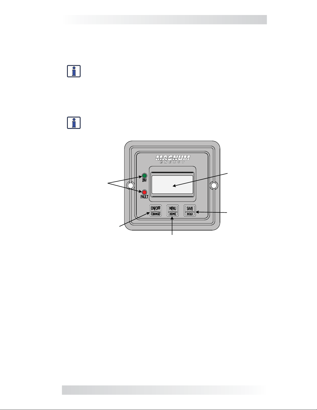
Figure 1-1, Front Panel Features
The ME-MR is equipped with the following features:
• LED Indicators – The at-a-glance LEDs provide a quick indication of
the inverter’s status, or notifi es you if a fault is present.
• LCD Display – The LCD display is a 8 x 2 line (16 characters total),
alphanumeric display used for setting up the inverter/charger operation, as
well as viewing current status or fault messages.
• ON/OFF or CHANGE Button – This button enables you to turn the
inverter on and off, and also serves as a “change” button to navigate through
the available settings for each menu.
• MENU or HOME Button – This button accesses the remote’s menus.
You can also return directly to the scrolling Home screens by pressing and
holding this button for 2 seconds. See also Figure 3-1.
• SAVE or HOLD Button – This button serves as a “save” button to
retain your settings. This button also is used as a “hold” button to stop the
Home screens from scrolling (press and hold the button for 2 seconds).
©2013 Magnum Energy, Inc. 1
Page 8

2.0 Installation
2.0 Installation
Review the Important Safety Instructions on page ii before proceeding with
the installation of your remote.
WARNING: Installations should be performed by qualifi ed per-
sonnel, such as a licensed or certifi ed electrician. The installer
determines which safety codes apply, and ensures all applicable
installation requirements are followed. Applicable installation codes
vary depending on the specifi c location and application.
2.1 Pre-Installation
Before proceeding, read the entire Installation section to determine how best
to install your ME-MR remote. The more thorough you plan in the beginning,
the better your inverter needs will be met.
2.1.1 Installation Guidelines
• Before connecting any wires, determine the remote cable’s route throughout the home or vehicle/boat both to and from the inverter.
• Always check for existing electrical, plumbing, or other areas of potential
damage before drilling or cutting into walls to mount the remote.
• Make sure all wires have a smooth bend radius and do not become kinked.
• If installing this remote in a boat, RV or truck, ensure the conductors
passing through walls, bulkheads, or other structural members are
protected to minimize insulation damage such as chafi ng, which can be
caused by vibration or constant rubbing.
2.1.2 Unpacking and Inspection
Carefully remove the ME-MR remote from its shipping container and inspect
all contents. Verify the following items are included:
• The ME-MR remote
• 25’ remote cable
• Two #6 x
• ME-MR Owner’s Manual
If items appear to be missing or damaged, contact your authorized Magnum
dealer or Magnum Energy, Inc. Save your proof-of-purchase as a record of
your ownership; it is needed if the unit should require in-warranty service.
½” Phillips screws
2.1.3 Tools Required
Installing the remote control is simple and requires the following tools:
• Phillips screwdriver • Level • Drill
• Cut-out tool (knife/saw) • Pencil • Drill bit (7/64”)
2.2 Installation Procedure
Select an appropriate location to install the ME-MR remote control. Allow
ample room to access the remote’s buttons and to view the LEDs. Ensure
the viewing angle of the display is appropriate. You can either fl ush mount
(concealing the connection) or surface mount the remote.
2 ©2013 Magnum Energy, Inc.
Page 9
2.0 Installation
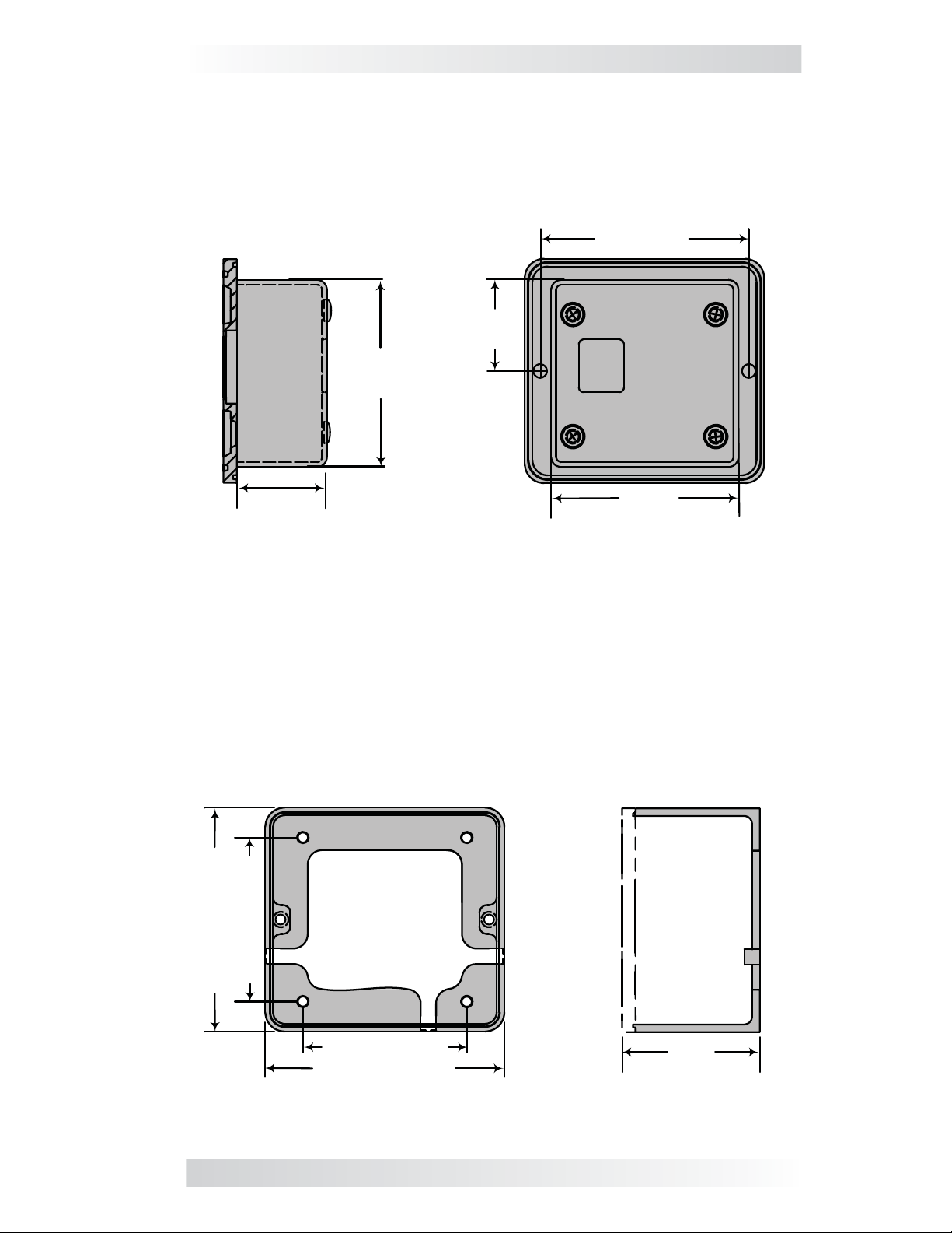
2.2.1 Flush Mounting the Remote
After selecting the desired location for fl ush mounting the remote, cut out
a square mounting hole measuring 2
remote into the cutout, and then use the remote to mark and pre-drill two
⅛” holes for the two supplied #6 x ½” Phillips fl at head mounting screws.
(2.86 cm)
2 ⅜"
(6.03 cm)
⅜” x 2⅜” (see Figure 2-1). Place the
"
11/16
2
(6.83 cm)
1 ⅛"
1 ⅛"
(2.86 cm)
Side view
2 ⅜"
(6.03 cm)
Back view
Figure 2-1, Cut-Out Dimensions for Flush Mounted Remote
2.2.2 Surface Mounting the Remote using the Bezel
After selecting the desired location for surface mounting the remote, use the
bezel (not supplied) as a template to mark the mounting holes. Mark and
pre-drill four
¾” screws.
x
⅛” holes (see Figure 2-2). Mount the bezel using the four #6
Bezel front view
Bezel side view
2 ⅛" (5.4 cm)
3 ⅛" (7.94 cm)
2 ⅛" (5.4 cm)
3 ⅛" (7.94 cm)
1
⅛
"
(2.86 cm)
Figure 2-2, Bezel Dimensions for Surface Mounted Remote
©2013 Magnum Energy, Inc. 3
Page 10
2.0 Installation
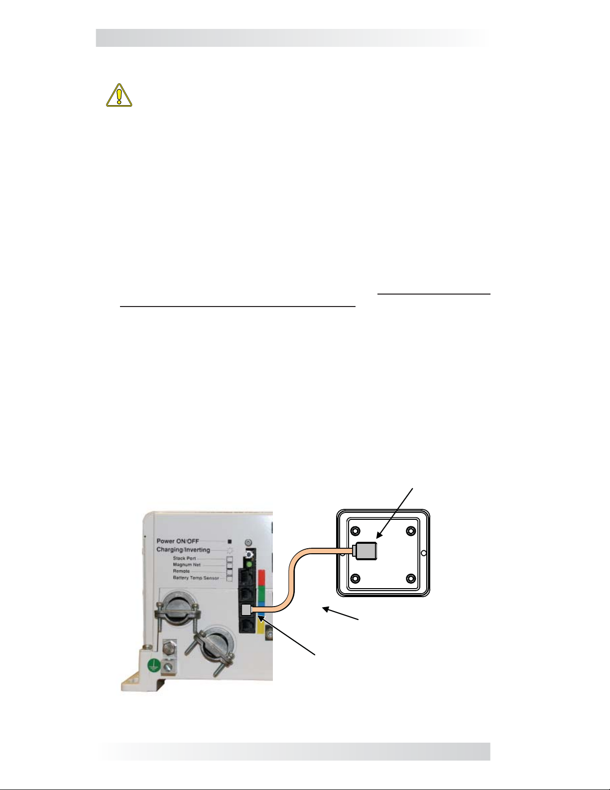
2.2.3 Connecting the Remote
CAUTION: When connecting battery power to the inverter, all battery
negative connections must be connected prior to the battery positive connections. When removing battery power from the inverter,
the battery positive should be removed before any battery negative
connections are disconnected. This prevents any communication
chips/lines from becoming the DC return path to the battery—causing
permanent damage to all connected accessories.
Summation: Ensure all battery negative circuits are always con-
nected before connecting or disconnecting battery positive.
1. Route the remote cable between the remote and the inverter/charger. This
25’ cable is a 4-wire telephony standard with RJ11 connectors on each
end. A standard telephone cable (with 4 conductors) may be substituted
if the provided remote cable cannot be used.
2. Connect the remote cable to the inverter/charger’s Remote port (blue
label). Refer to Figure 2-3.
3. Connect the inverter to the batteries, but ensure the inverter is off and
that no AC power is connected to the inverter.
4. While monitoring the front of the remote, connect the other end of the remote cable into the RJ11 jack on the back side of the remote (Figure 2-3).
5. Immediately upon connecting the remote cable the LEDs will illuminate
as the unit goes through a self-test. After the initial self-test, text should
appear with a system status message indicating the current state of
the inverter/charger. If not, please refer to the Troubleshooting section.
6. Next, mount the remote to the desired surface or to the bezel (using
the two supplied #6 x
for setup.
½” Phillips fl at head screws). The remote is ready
RJ11 Connection
B
A
C
Magnum Inverter
K
Remote Cable
Remote Port (blue)
Figure 2-3, Remote Control Connections
4 ©2013 Magnum Energy, Inc.
Page 11
3.0 Setup
3.0 Setup
When the ME-MR remote is connected to a Magnum inverter/charger, the
remote’s settings determine the inverter/charger’s operating parameters.
The default settings in the remote (see Table 3-4) are adequate for most
installations. However, you can change some of the operating parameters if
needed. This section shows you how to navigate the remote, and gives you
an understanding of the function of each adjustable setting.
3.1 Navigating the Remote
The ME-MR has menu items and adjustable settings that provide the ability to
confi gure your inverter/charger to your specifi c parameters.
Info: See Figure 4-1 for a complete map of the remote’s menu
items and adjustable settings.
The items on the remote’s front panel are used to fi nd, adjust, and save the
desired setting. They are:
• LCD Display – The LCD display shows menu items, adjustable settings,
and the meter’s display information.
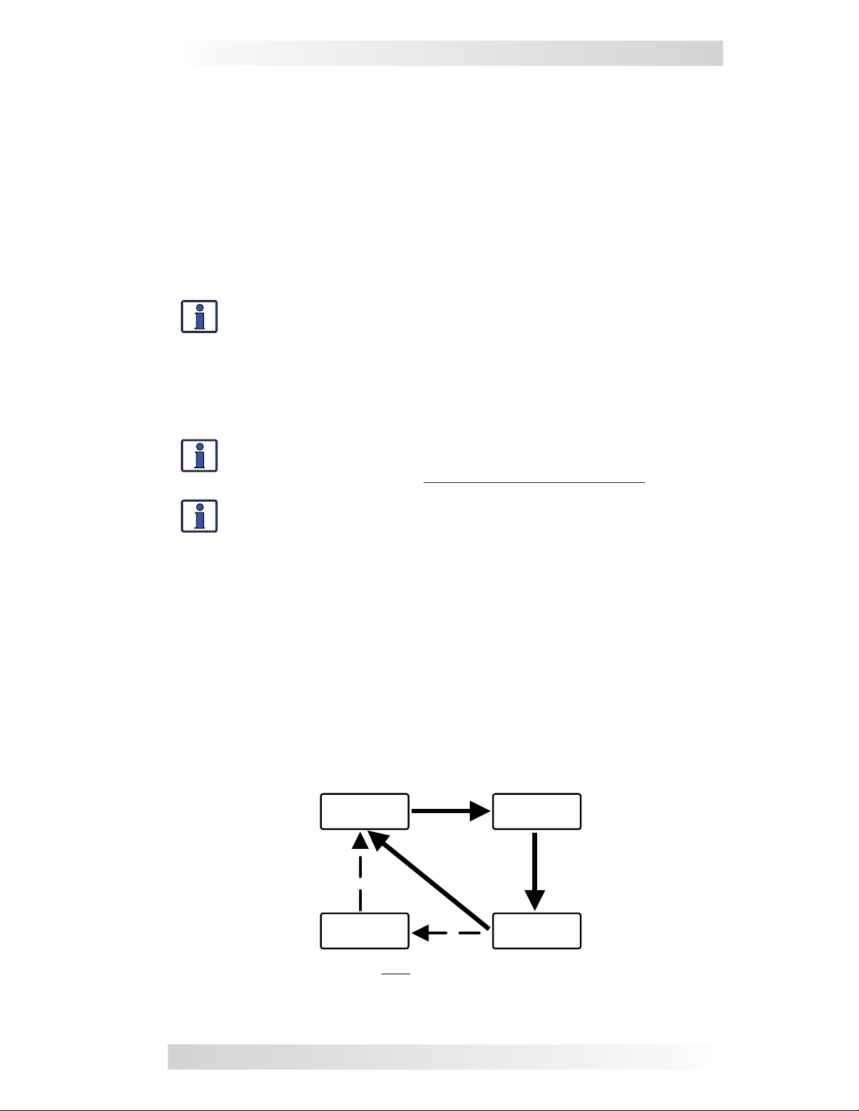
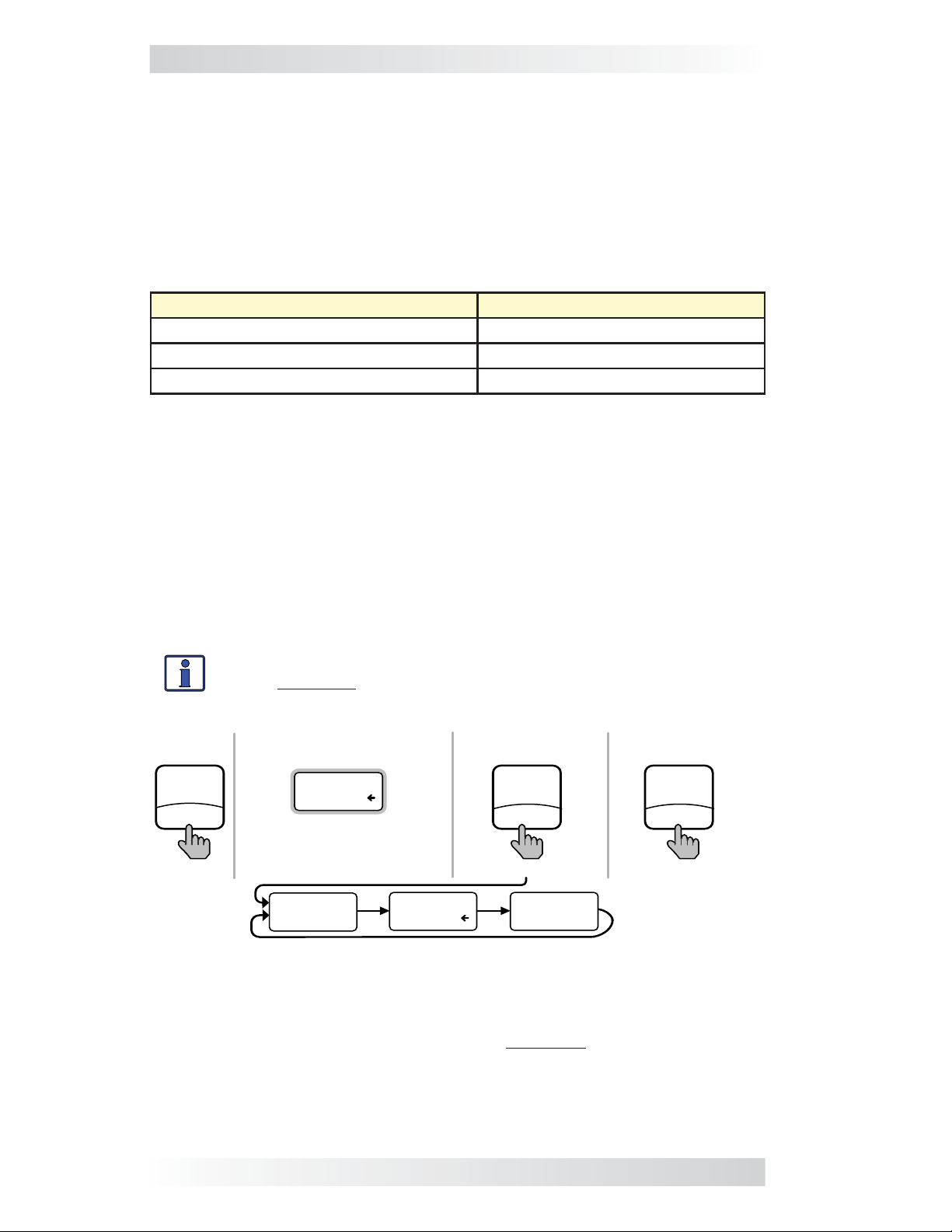
Info: The LCD display returns to the scrolling Home screens to show
inverter status, DC voltage and current, and any fault present (if applicable) after 30 seconds—if no buttons have been pressed.
Info: When the ”←” (left facing arrow) symbol is shown on the
display, it indicates that the displayed setting has been selected
and will be used.
• ON/OFF/CHANGE Button – Allows you to quickly scroll through and
select various menu items and settings after pressing the MENU button.
• MENU/HOME Button – Allows easy access to the menu items that can
help with confi guring, monitoring, and troubleshooting your inverter/
charger. Press and hold this button (2 seconds) to return to the scrolling
Home screens (Figure 3-1).
• SAVE/HOLD Button – Saves the menu item displayed on the screen. A
saved setting is denoted by the arrow symbol. Press and hold this button
(2 seconds) to stop the Home screens from scrolling (“HOLD” displays).
Press once to view the next Home screen. Press and hold again (2 sec-
onds) to resume scrolling of the Home screens (“SCROLL” displays).
Inverter/Charger
Status
STATUS
Invert
BATTERY
11.4V
Battery Voltage
Inverter/Charger
Fault
Note: Fault screen only appears if a fault has been detected
FAULT !
Low Batt
BATTERY
- 0A
Battery Current
Figure 3-1, Scrolling Home Screens
©2013 Magnum Energy, Inc. 5
Page 12
3.0 Setup
3.2 Remote Menu Items
This section covers the function of each menu item and explains what confi gurable settings are available from each menu.
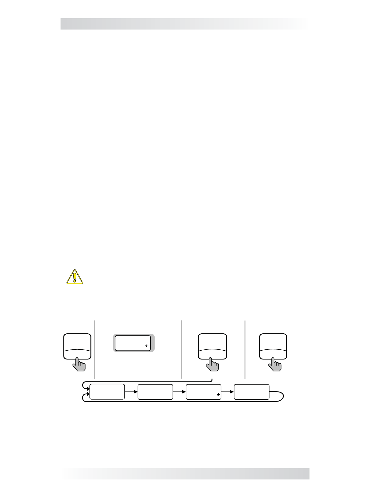
3.2.1 AC IN Menu
Use this menu as a quick means of changing your AC IN setting to coordinate
with the circuit breaker rating from the incoming AC source.
• AC IN – This selection ensures the inverter’s AC loads receive the maxi-
mum current available from the utility or your generator power. Whenever
the utility or generator is connected to the inverter, the current used to
power the AC loads and to charge the batteries is monitored. When the
total current used to power the AC loads and charge the batteries begins
to approach the AC IN setting, the current that was used for charging
the batteries will automatically be reduced. This ensures the AC loads
have all the available current when needed. The feature is not available
on MM and MMS Series inverter/chargers.
Default setting: AC IN = 30 Amps
Range: 5 Amps, 15 Amps, 30 Amps, 50 Amps
Where to set: Adjust the AC IN setting to match the current rating of the
utility power or the generator’s circuit breaker. If using multiple AC sources
(utility and generator) through an AC transfer switch, adjust this setting to
the smaller AC breaker size. This setting is dependent on the stability of the
AC source. If using a generator, factors such as altitude and output voltage
regulation may require a lower setting than the generator’s breaker size. If
the breaker on the AC source is tripping (because it is a weak breaker), try
reducing this setting to the next lower level.
Note: If the ME-MR is connected to a MSH-RE inverter, the AC IN setting
applies to both inputs (AC1 and AC2).
MENU
HOME
press
CAUTION: The AC IN setting does not limit the current to the
inverter loads. If the current to the loads on the output of the inverter are greater than the circuit breaker rating on the incoming
AC source, you may experience nuisance tripping of this breaker.
Bottom line shows
current “saved” setting
AC IN
30 Amps
If this setting is correct,
press MENU button to
access different menu items
AC IN
5 Amps
AC IN
15 Amps
If a different setting
is required:
ON/OFF
CHANGE
press
AC IN
30 Amps
To save the current
setting displayed:
SAVE
HOLD
press
AC IN
50 Amps
Figure 3-2, AC IN Selections
6 ©2013 Magnum Energy, Inc.
Page 13
3.0 Setup
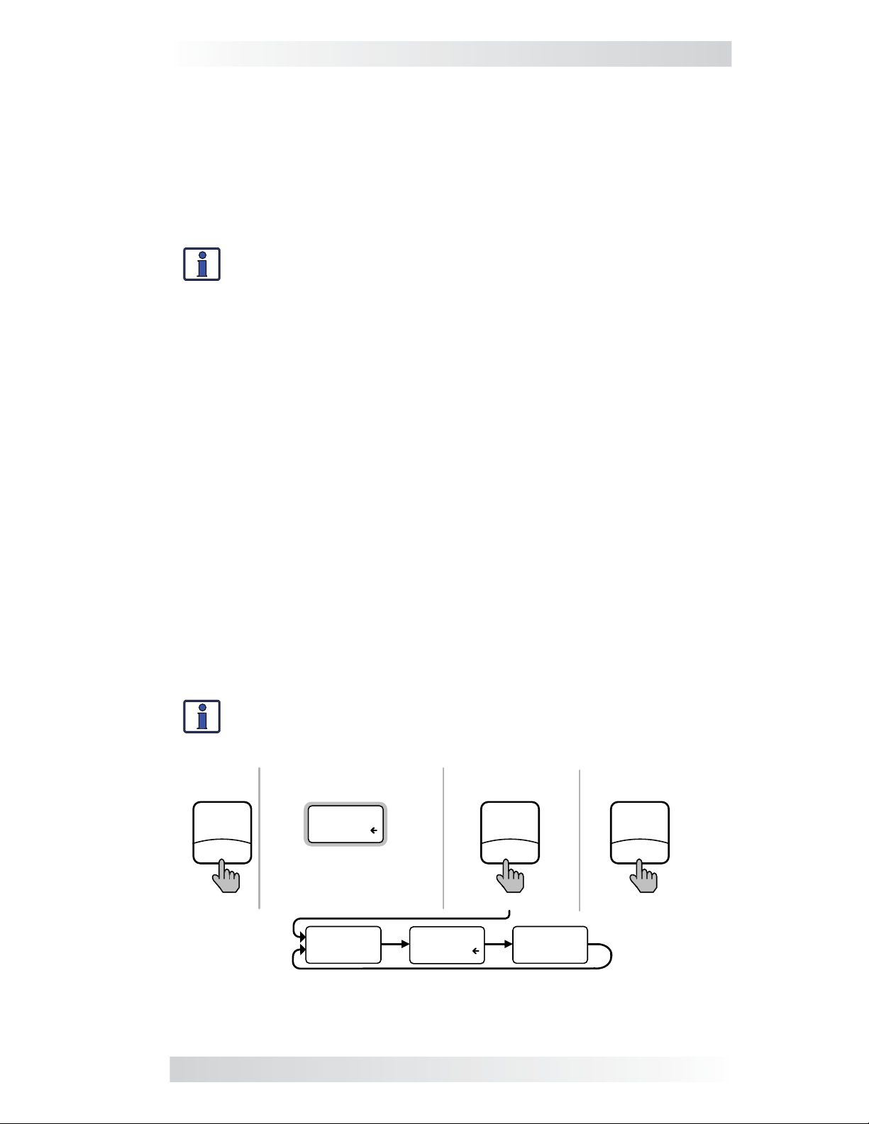
3.2.2 Search Watts Menu
• SEARCH – This selection allows you to turn off the Search Watts feature,
or to adjust the power level to determine when the feature becomes
active. If this feature is not needed, select SEARCH = Off. When the
Search Watts feature is turned off, the inverter continuously provides
full AC voltage to the loads.
Default setting: SEARCH = 5 Watts
Range: Off, 5 Watts, 20 Watts
Info: When the Search Watts feature is active “Search” appears
on the bottom line of the LCD display, and the green INV LED will
slowly fl ash.
What is the Search Watts feature? This feature is used to help save bat-
tery power by reducing the inverter’s output to search pulses when there
is no detectable load. If someone turns on a load greater than the wattage
level setting while the inverter is searching, the inverter will start inverting
to provide full voltage on its output.
Should I use the Search Watts feature? If the inverter can spend a great
deal of time searching (to reduce the power drain on your batteries) and you
can tolerate small loads (less than 5 watts) from being on, then the Search
Watts feature should be used. However, if you require some small loads (e.g.,
digital clocks, satellite receivers, answering machines, etc.,) to always be on,
then this feature should be turned off (SEARCH = Off).
Where to set: The SEARCH Watts setting should be adjusted to the same
power level (or the next lower setting) of the smallest load that you want to
run. If you don’t know the wattage of the smallest load you want to run, turn
the switch for the load on and then decrease the SEARCH Watts setting until
the load comes on and stays on.
Example: You have reviewed all the loads you want to run and determined that the smallest load is a 20 watt light. Set SEARCH = 20 Watt.
Whenever you turn on any load (because all the loads are greater than
20 watts), the inverter will stop searching and start inverting to deliver
power to the load.
Info: Even though the Search Watts feature is on, some connected
equipment may draw enough current even while off to keep the
inverter in Invert mode.
To save the current
setting displayed:
SAVE
HOLD
press
MENU
HOME
press
Bottom line shows
current “saved” setting
SEARCH
5 Watt
If this setting is correct,
press MENU button to
access different menu items
SEARCH
Off
SEARCH
5 Watt
If a different
setting is required:
ON/OFF
CHANGE
press
SEARCH
20 Watt
Figure 3-3, Search Watts Selections
©2013 Magnum Energy, Inc. 7
Page 14
3.0 Setup
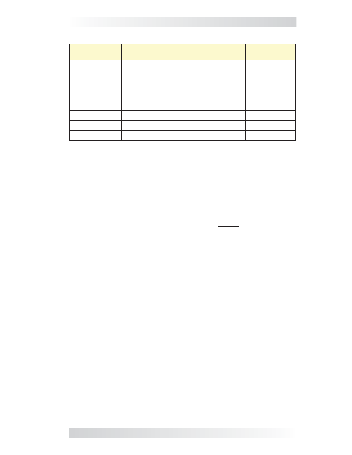
3.2.3 Battery Amp-Hours Menu
• BAT AHRS – This selection is used to select the approximate capacity
of the battery bank that is connected to the inverter (in battery amphours). This setting determines the time the battery charger is in the
Absorb Charging stage (i.e., absorption time). See Table 3-1 to correlate
the battery capacity to the absorption time.
Default setting: BAT AHRS = 400 AH
Range: 200 AH, 400 AH, 800 AH
Table 3-1, Battery Amp-Hrs to Absorb Charging Time
Battery Amp-Hours Selected Absorb Charging Time
Batt AmpHrs = 200 60 minutes
Batt AmpHrs = 400 90 minutes
Batt AmpHrs = 800 120 minutes
Where to set: Select the setting based on the 20-hour Amp-Hour (AH)
capacity of your battery bank.
How do I determine my battery AH capacity? The inverter requires deep
cycle batteries, which are specifi cally made for continuous use. Deep cycle
batteries are rated either by: a) amp-hours, or b) reserve capacity in minutes.
• Amp-hour (AH) capacity is a measurement of how many amps a battery
can deliver for a specifi ed length of time (usually 20 hrs) until the
voltage achieves 1.75 VDC/cell at 80° F.
• Reserve Capacity (RC) is a measure of how many minutes a battery can
deliver a certain amount of current (usually 25A) while maintaining a
voltage above 1.75 VDC/cell at 80° F.
Info: If using the Reserve Capacity (25A), the 20 hour AH capacity
can be estimated by multiplying ‘reserve capacity’ by 50%.
To save the current
setting displayed:
SAVE
HOLD
press
MENU
HOME
press
Bottom line shows
current “saved” setting
BAT AHRS
400 AH
If this setting is correct,
press MENU button to
access different menu items
BAT AHRS
200 AH
BAT AHRS
400 AH
If a different setting
is required:
ON/OFF
CHANGE
press
BAT AHRS
800 AH
Figure 3-4, Battery Amp-Hours Selections
Table 3-2 on the facing page provides an estimated 20 hour AH capacity
based on the group/code size, physical size, and the voltage of the battery.
If you are not sure of your battery’s 20 hour AH rating, consult your battery
manufacturer/dealer or use Table 3-2 to obtain an estimate.
8 ©2013 Magnum Energy, Inc.
Page 15
3.0 Setup
Table 3-2, Battery Size to Battery Amp-Hours (estimated)
Group/
Code Size
GC-2 (Golf Cart) 10
L16 11
Group 22 9
Group 24 10
Group 27 12
Group 31 13 x 6
4D 20
8D 20
Physical Size
(L” x W” X H”)
3/8 x 7 13/16 x 10 5/8 6V 220 AHrs
11/16 x 7 x 16 11/16 6V 375 AHrs
1/2 x 6 7/8 x 8 5/16 12V 55 AHrs
1/4 x 6 13/16 x 8 7/8 12V 70 AHrs
1/16 x 6 13/16 x 8 7/8 12V 95 AHrs
13/16 x 9 7/16 12V 110 AHrs
3/4 x 8 3/4 x 9 7/8 12V 200 AHrs
3/4 x 11 1/8 x 9 7/8 12V 225 AHrs
Battery
Voltage
Battery AHrs
(20 hour rate)
Once you’ve determined the AH capacity of each battery, review how your
batteries are connected (parallel or series) to determine the total amp-hour
capacity of the battery bank.
Parallel connection
When batteries are connected in parallel (positive to positive, negative to
negative) they increase the amp-hour capacity of the battery bank, but the
voltage remains the same.
Example: You have a 12-volt battery bank with three 12-volt batteries
that are rated at 125 amp-hours (AH) each. Each of the positive terminals
are connected together and each of the negative terminals are connected
together, which means they are connected in parallel. The amp-hours of
each battery connected in parallel are added together (125 AH + 125 AH
+ 125 AH = 375 AH), but the voltage of the battery bank stays the same
(12 VDC).
Series connection
When batteries are connected in series (positive to negative) they increase
the voltage of the battery bank, but the amp-hour rate remains the same.
Example: You have a 12-volt battery bank with two 6-volt batteries
that are rated at 220 amp-hours (AH) each. The positive terminal of
the fi rst battery is connected to the negative terminal of the second
battery, which means these batteries are connected in series. Since the
two 6-volt batteries are connected in series, the voltage of the batteries
are added together to produce 12-volts (6 VDC + 6 VDC = 12 VDC), but
the amp-hour capacity of the battery bank does not change (220 AH).
In battery banks where you have batteries connected in series and in parallel
—the rules are the same. The batteries connected in series are referred to
as a “series string” and the amp-hour capacity doesn’t change. Each series
string is connected together in parallel to increase the amp-hour capacity.
Add the amp-hour capacity of each series string connected in parallel to
determine the total amp-hour capacity of the battery bank.
©2013 Magnum Energy, Inc. 9
Page 16

3.0 Setup
3.2.4 Battery Type Menu
• BAT TYPE – This menu is used to select the battery type, which
determines the battery charge profi le and ensures the batteries are
receiving the proper charge voltage. The fi xed voltage options are: GEL
(for Gel batteries), Flooded (for liquid lead acid batteries), AGM 1 (for
Lifeline AGM batteries), and AGM 2 (for East Penn/Deka/Discover/Trojan
AGM batteries). Refer to Table 3-3 to determine the specifi c charge
voltage based on the battery type selected.
Default setting: BAT TYPE = Flooded
Info: The voltage settings shown in Table 3-3 are based on the
Battery Temperature Sensor (BTS) being disconnected, or at a
temperature of 77° F (25° C). If the BTS is connected, the actual
charge voltage increases if the temperature around the BTS is colder
than 77° F (25° C), and decreases if hotter than 77° F (25° C). This
ensures the batteries receive the correct charge voltage even if they
become cold or hot.
Table 3-3, Battery Type to Charge Voltages
Battery
Type
GEL
Inverter
Voltage
Absorption
Voltage
Float
Voltage
Equalization
Voltage
12 VDC 14.1 VDC 13.6 VDC 14.1 VDC
24 VDC 28.2 VDC 27.2 VDC 28.2 VDC
48 VDC 56.4 VDC 54.4 VDC 56.4 VDC
1
1
1
12 VDC 14.6 VDC 13.4 VDC 15.5 VDC
Flooded
24 VDC 29.2 VDC 26.8 VDC 31.0 VDC
48 VDC 58.4 VDC 53.6 VDC 62.0 VDC
12 VDC 14.3 VDC 13.1 VDC 15.5 VDC
2
AGM 1
24 VDC 28.6 VDC 26.2 VDC 31.0 VDC
48 VDC 57.2 VDC 52.4 VDC 62.0 VDC
1
1
1
AGM 2
12 VDC 14.5 VDC 13.5 VDC 14.5 VDC
3
24 VDC 29.0 VDC 27.0 VDC 29.0 VDC
48 VDC 58.0 VDC 54.0 VDC 58.0 VDC
Note 1: Voltage same as absorption voltage – to prevent equalization.
Note 2: Specifi cations for Concord (Lifeline Series) AGM batteries.
Note 3: Specifi cations for East Penn, Deka, Discover and Trojan AGM batteries.
Bottom line shows
current “saved” setting
If a different setting
is required:
To save the current
setting displayed:
MENU
HOME
press
BAT TYPE
Flooded
If this setting is correct,
press MENU button to
access different menu items
BAT TYPE
GEL
BAT TYPE
Flooded
ON/OFF
CHANGE
press
BAT TYPE
AGM 1
SAVE
HOLD
press
BAT TYPE
AGM 2
Figure 3-5, Battery Type Selections
10 ©2013 Magnum Energy, Inc.
Page 17

3.0 Setup
3.2.5 Charge Rate Menu
• CHG RATE – This selection is used to set the maximum charge rate
allowed to charge the batteries during Bulk, Absorption, Float, and
Equalize charging. The CHG RATE = 10% setting is available to help
minimize charging, while continuing to allow pass-through power.
Default setting: CHG RATE = 100%
Range: 10%, 50%, 100%
The charge rate selections are provided as a percentage of the inverter/
charger’s maximum charging capability. Refer to the label on the side of
the inverter or to the inverter/charger owner’s manual to determine its
maximum charge rate. Once you fi nd this maximum charge rate, determine
the percentage needed to limit the charge rate to your battery bank.
Example: If the maximum charge rate of your inverter/charger is 100
amps and you need to limit the charge rate to 50 amps, choose the CHG
RATE = 50% selection (50 amps = 50% of 100 amps).
Info: The topology of the Magnum inverter when connected to an
AC source overrides the setting, and starts charging if the battery
voltage is <12 VDC (12-volt models), <24 VDC (24-volt models)
or <48 VDC (48-volt models).
Where to set: The maximum charge rate is generally set to a C/5* rate (C =
the total amp-hour capacity of the battery bank—using the 20 hour AH rate).
The C/5 rate is usually used when the objective is to charge the batteries as
quickly as possible (i.e., 400 AH ÷ 5 = 80 amp maximum charge rate). A lower
rate such as C/20* is used when the batteries need to be charged as slow as
possible. The ME-MR provides three settings for charge rate adjustment—10,
50, and 100%. Multiply this percentage and the max charge rate of the
inverter to fi nd the closest setting to the desired charger output.
CAUTION: The C/5 or C/20 charge rate settings are guidelines;
they are not requirements on how you should set your battery
charge rate. For specifi c charge rate requirements, refer to your
battery manufacturer.
Info: If multiple inverter/chargers are used on a single battery
bank, you must ensure that the total charge rate from all inverter/
chargers is limited to the max charge rate needed for your battery
bank. This setting only limits the charging on each inverter/charger
individually, not on all inverter/chargers.
* C/5 or C/20 rate – Charge rates are commonly expressed as a ratio of the total
amp-hour (AH) capacity of the battery bank. For example, with a 400 AH battery
bank (C = 400), the C/5 charge rate is 80 A (400/5 = 80 A).
To save the current
setting displayed:
SAVE
HOLD
press
MENU
HOME
press
Bottom line shows
current “saved” setting
CHG RATE
100%
If this setting is correct,
press MENU button to
access different menu items
CHG RATE
10%
If a different setting
CHG RATE
50%
is required:
ON/OFF
CHANGE
press
CHG RATE
100%
Figure 3-6, Charge Rate Selections
©2013 Magnum Energy, Inc. 11
Page 18

3.0 Setup
3.2.6 Low Battery Cut-Out (LBCO) Menu
• LBCO – This menu is used to set the DC voltage level that turns off
the inverter to help protect the batteries from over-discharge damage.
Selections are from 9 VDC to 11 VDC (12-volt inverter models), 18 VDC
to 22 VDC (24-volt inverter models), or 36 VDC to 44 VDC (48-volt
inverter models). If the battery voltage drops below the LBCO selected
setpoint continuously for more than one minute, the FAULT LED will
come on, the inverter will turn off, and the display shows “FAULT! Low
Bat” (low battery status). If the battery voltage falls below 8.5 volts (12-
volt models), 17.0 volts (24-volt models) or 34.0 (48-volt models), the
FAULT LED and Low Bat status will be immediate.
Default settings: LBCO = 10 VDC (12-volt models), 20 VDC (24-volt
models) or 40 VDC (48-volt models).
Range: 9 VDC, 10 VDC, 11 VDC (12-volt models, x2 for 24v, x4 for 48v)
Info: The inverter will automatically begin to start inverting when
the DC voltage increases to ≥ 12.5 VDC (12-volt models), ≥ 25.0
VDC (24-volt models) or ≥ 50.0 VDC (48-volt models). If AC power
is available and connected to the inverter’s input the inverter will
automatically clear the Low Battery fault, pass the input AC power
to the output, and begin charging the batteries.
Where to set: To cycle the batteries slightly but not discharge them more
than 20%*, the LBCO setting should be set to 11 VDC (12-volt models), 22
VDC (24-volt models) or to 44 VDC (48-volt models). In some applications,
such as installations in an off-grid home or when doing a lot of dry-camping
in your RV, you may want to cycle down to 25%* by setting the LBCO to
10 VDC (12-volt models), 20 VDC (24-volt models) or to 40 VDC (48-volt
models). In extreme circumstances, you have the ability to discharge the
batteries to 80%* by setting the LBCO to 9 VDC (12-volt models), 18 VDC
(24-volt models), or to 36 VDC (48-volt models) before recharging.
* These discharge percentages are rough estimates; for accurate battery monitoring,
a battery monitor such as Magnum’s ME-BMK and the ME-RC remote is required.
Info: The inverter will automatically begin to start inverting when the
DC voltage increases to ≥ 12.5 VDC (12-volt models), ≥ 25.0 VDC
(24-volt models) or to ≥ 50.0 VDC (48-volt models). If AC power
is available and connected to the inverter’s input, the inverter will
automatically clear the Low Battery fault, pass the input AC power
to the output, and begin charging the batteries.
MENU
HOME
press
Bottom line shows
current “saved” setting
LBCO
10 VDC
If this setting is correct,
press MENU button to
access different menu items
If a different setting
is required:
ON/OFF
CHANGE
press
To save the current
setting displayed:
SAVE
HOLD
press
LBCO
9 VDC
Note: Values shown are for a 12-volt inverter
LBCO
10 VDC
LBCO
11 VDC
Figure 3-7, LBCO: Low Battery Cut-Out Selections
12 ©2013 Magnum Energy, Inc.
Page 19

3.0 Setup
3.2.7 VAC Dropout Menu
• VAC DROP – This selection is used to set the minimum AC voltage that
must be present on the input before the inverter/charger switches from
Invert to Charge mode. For example, if this setting is set to VAC DROP
= 60 VAC, then the AC input voltage must be above 60 volts before the
inverter will switch from Invert mode to Charge mode. This setting also
determines the minimum AC voltage threshold where the inverter/charger transfers from the AC input (utility/shore or generator) and begins
inverting. This protects AC loads from utility outages.
Default setting: VAC DROP = 80 VAC for North American units; 150
VAC for export models.
Range: 60 VAC, 80 VAC, and 100 VAC for 120v units (North America);
and 110 VAC, 150 VAC, and 190 VAC for 230v units (for export)
Where to set: It depends on the application and what you are using as the
AC source. The settings not only look at the incoming voltage to determine
when to transfer, but they also determine the response sensitivity to incoming
voltage fl uctuations. Use the 100 VAC dropout setting when the AC source
is well regulated and you are operating devices that are sensitive to voltage
fl uctuations. Use the 80 VAC or lower setting (60 VAC) when the AC source
may have signifi cant fl uctuations in RMS voltage. These settings are highly
recommended if using a generator for charging.
Note: If the ME-MR is connected to a MSH-RE inverter, the VAC Dropout
setting applies to both inputs (AC1 and AC2).
If a different setting
is required:
ON/OFF
CHANGE
VAC DROP
80 VAC
press
VAC DROP
100 VAC
To save the current
setting displayed:
SAVE
HOLD
press
MENU
HOME
press
Bottom line shows
current “saved” setting
VAC DROP
80 VAC
If this setting is correct,
press MENU button to
access different menu items
VAC DROP
80 VAC
Figure 3-8, VAC Dropout Selections
3.2.8 Power Save Menu
• PWR SAVE
on or off.
Default setting:
Range:
What is the Power Saver feature? The Power Saver feature causes the
LCD backlight and LEDs on the remote display to turn off to conserve energy.
The remote goes into Power Saver mode if there has not been a button press
or fault message for 15 minutes. Whenever the remote goes into the Power
Saver mode, the LCD backlight and LEDs can be
button on the remote.
–
On, Off
This setting allows you to turn the Power Save feature
PWR SAVE = On
reactivated by pressing any
©2013 Magnum Energy, Inc. 13
Page 20

3.0 Setup
If you have a fault during the Power Saver mode, the LCD backlight, and the
FAULT LED will come on and stay on as long as the fault is detected. If you
want the LCD backlight and LEDs to always be on, select PWR SAVE = Off.
MENU
HOME
press
Bottom line shows
current “saved” setting
PWR SAVE
On
If this setting is correct,
press MENU button to
access different menu items
PWR SAVE
Off
If a different setting
is required:
ON/OFF
CHANGE
press
PWR SAVE
On
To save the current
setting displayed:
SAVE
HOLD
press
Figure 3-9, Power Saver Selections
3.2.9 Equalize Menu
• EQUALIZE – This menu allows you to equalize the batteries after a Float
Charge is achieved. Equalizing should only be attempted by experienced
users.
Default setting: EQUALIZE = Disabled
Range: Disabled, Request, EQing
What is equalizing? Equalizing is a controlled overcharge of the batteries.
During this process, there will be excessive gassing of the batteries. This
condition is not only corrosive, but can also be dangerous as hydrogen
gasses are emitted during the charging process.
WARNING: Only equalize in well ventilated areas. Consult your
battery’s manufacturer for recommendations on equalizing.
Info: Equalization can only be accomplished when the charger status
is “FLOAT” or “Full Chg”.
Info: Equalization charging is not available if either GEL or AGM 2 is
selected from the Battery Type menu.
MENU
HOME
press
Bottom line shows
current “saved” setting
EQUALIZE
Disabled
If this setting is correct,
press MENU button to
access different menu items
EQUALIZE
Disabled
EQUALIZE
Request
EQUALIZE
EQing
To start
equalization:
ON/OFF
CHANGE
press
Figure 3-10, Equalize Selections
14 ©2013 Magnum Energy, Inc.
Page 21

3.0 Setup
3.2.10 Charger Standby Menu
• CHARGER – Select whether to activate Charger Standby mode after
AC power is connected (charger ready and waiting for AC input).
Default setting: CHARGER = No AC In
Range: No AC In, Chg Stby
What is Charger Standby? When the charger is in Charger Standby, the
incoming AC is still available on the inverter’s output, but the charger is not
allowed to charge.
Info: To resume charging, access the Charger Standby menu and
press the CHANGE button.
Info: If upon accessing this menu “No AC In” displays, you will not be
able to change the Charger’s status.
Bottom line shows
current charger status
MENU
CHARGER
Absorb
HOME
This status will not change
until AC is connected
press
CHARGER
Status
Possible statuses:
Absorb, Bulk, Charging, Equalizing (EQing), Float
(Full Chg), Load Support AAC (LS AAC), Load Support VDC (LS VDC)
CHARGER
Chg Stby
If a different status
is required:
ON/OFF
CHANGE
press to change status
, Full Charge
Figure 3-11, Charger Standby Selections
3.2.11 Power On Menu
• POWER ON – Select whether to have the inverter power up and provide
AC power automatically once DC voltage is connected to it.
Default: POWER ON = Norm
Range: Norm (Normal), Always
What is the Power On feature? Normally, when DC power is connected
to the inverter, the user is required to press the power button—on the
inverter or remote—to turn the inverter on (Norm). When the Power On
feature is activated by selecting Always, the inverter is automatically turned
on and starts searching or inverting—depending on the Search Watts setting
(see Section 3.2.2). Once the inverter has connected to DC power and is
automatically turned on, the power button—on the inverter or remote—can
be used to turn the inverter on or off.
Why use the Power On feature? Some customers are familiar with
Uninterruptible Power Supplies (UPS) that power-up automatically when DC
power is connected. The Power On feature can be used by customers that
want to obtain the same automatic power-up feature with which they are
familiar.
©2013 Magnum Energy, Inc. 15
Page 22

3.0 Setup
MENU
HOME
press
Bottom line shows
current “saved” setting
POWER ON
Norm
If this setting is correct,
press MENU button to
access different menu items
POWER ON
Norm
If a different setting
is required:
ON/OFF
CHANGE
press
POWER ON
Always
To save the current
setting displayed:
SAVE
HOLD
press
Figure 3-12, Power On Selections
3.2.12 TECH Menu
• TECH – This menu provides access to read only system information
that can assist service technicians in troubleshooting. It also offers a
selection that enables you to return all system settings to the original
factory default values, and another that locks some setup menus.
Scroll to the end of the remote’s menus until “TECH, Press ON” appears. Press
the ON/OFF CHANGE button to access these selections. Continue to press the
ON/OFF CHANGE button to view each TECH menu item.
Bat Temp: Displays the temperature of the battery temperature sensor
(BTS)—if connected.
Xfm Temp: Displays the temperature of the inverter’s transformer.
FET Temp: Displays the temperature of the FETs (Field Effect Transistors).
Inverter Rev: Displays the fi rmware revision level of the inverter.
Remote Rev: Displays the fi rmware revision level of the remote.
Model: Displays the model number of the connected inverter.
Info: If “Model Unknown” displays, the remote is unable to determine
the inverter model. This may be due to an inverter revision newer
than the remote. All remote menu selections/features that are available in the inverter will function normally.
Ext Ctrl: Magnum has an open protocol policy that allows certain functions
(AC In, Charge Rate, & VAC Dropout settings) of the inverter/charger to be
controlled externally—such as with a third party communications device.
No – there is no external device controlling any of the inverter’s settings.
INT – an external device is controlling the setting—however, the
external device has not changed the setting at this time.
EXT – an external device is controlling the setting—and, the external
device has changed the setting.
When an external device is connected, the above menus scroll across the
bottom line of the display. The INT or EXT display denotes whether the
setting has been changed. Example:
An external device is connected, the AC IN and Charge Rate settings
have not been changed, but the VAC Dropout setting has been changed.
SETUP: Allows you to Lock or Unlock the setup menus on your remote.
Press the SAVE/HOLD button to select to lock the setup menus (Lock) or
to unlock (Unlock) the setup menus.
Note: Exception - AC In menu does not lock.
AC IN INT...CHR% INT...VAC EXT.
16 ©2013 Magnum Energy, Inc.
Page 23

3.0 Setup
Press the ON/OFF button to
to view TECH menus
MENU
TECH
Press ON
HOME
TECH menus are “read only”
displays, no changes can be
press
Bat Temp
xx C
Defaults*
5.0 secs
* Press and hold the SAVE/HOLD button to restore defaults
**Press the SAVE/HOLD button to select Lock or Unlock
made to these screens*/**
Xfm Temp
xx C
FET Temp
SETUP**
Lock
xx C
Ext Ctrl
No
To scroll next
Inverter
Rev x.x
xxxxxx
screen:
ON/OFF
CHANGE
press
Remote
Rev 1.1
Model
Figure 3-13, TECH Menus
Defaults: This menu restores all settings on the ME-MR (and in the in-
verter/charger) to the original factory default settings. To restore, press
and hold the SAVE/HOLD button for 5 seconds (see Figure 4-1). After
the default settings have been restored, the display will show “Loaded”.
The ME-MR factory defaults are listed in Table 3-4.
Table 3-4, ME-MR’s Inverter/Charger Default Settings
Menu Default Setting
AC In AC IN = 30 Amps
Search Watts SEARCH = 5 Watt
Battery Amp-Hours
Battery Type BAT TYPE = Flooded
Charge Rate CHG RATE = 100%
LBCO = 10 VDC (12-volt models),
Low Battery Cut Out
Low VAC Dropout VAC DROP = 80 VAC (150 VAC for export)
Power Save PWR SAVE = On (15 min.)
Equalize EQUALIZE = Disabled
Charger Standby
(Charger Standby is off, will automatically
BAT AHRS = 400 AH
(Absorb Time = 90 min.)
20 VDC (24-volt models),
40 VDC (48-volt models)
CHARGER = No AC In
charge when AC is connected)
Power On POWER ON = Norm
TECH: SETUP SETUP = Unlock
©2013 Magnum Energy, Inc. 17
Page 24

4.0 Menu Map
4.0 Menu Map: ME-MR Remote Control
This menu map is an overview of the inverter/charger settings (arrows denote
factory defaults) and the info displays available from the ME-MR remote.
MENU
HOME
AC IN
AC IN
5 Amps
AC IN
15 Amps
15 Amps
AC IN
30 Amps
AC IN
50 Amps
SEARCH
Off
BAT AHRS
200 AH
BAT TYPE
GEL
CHG Rate
10%
LBCO
9 VDC
VAC DROP
60 VAC
PWR SAVE
Off
EQUALIZE
Disabled
CHARGER
Status
SEARCH
5 Watt
BAT AHRS
400 AH
BAT TYPE
Flooded
CHG Rate
50%
LBCO
10 VDC
VAC DROP
80 VAC
PWR SAVE
On
EQUALIZE
Request
CHARGER
Chg Stby
SEARCH
20 Watt
BAT AHRS
800 AH
BAT TYPE
AGM 1
BAT TYPE
AGM 2
CHG Rate
100%
LBCO
11 VDC
VAC DROP
100 VAC
EQUALIZE
EQing
Note: Upon accessing this menu, if “No AC
In” displays, you cannot put into Charger
Standby.
Range:
24v = 18VDC, 20VDC, 22VDC
48v = 36VDC, 40VDC, 44VDC
Export models:
Range: 110VAC, 150VAC, 190VAC
Default: 150VAC
Note: Upon accessing this menu,
the charger must be in Float or
Full Charge status to equalize.
POWER ON
Norm
POWER ON
Always
TECH
Press ON
Bat Temp
XX C
Model
XXXXXX
Ext Ctrl
No
Xfm Temp
XX C
Remote
Rev 1.1
SETUP
Unlock
SETUP
Lock
FET Temp
XX C
Inverter
Rev X.X
Defaults
5.0 secs
Defaults
Loaded
Figure 4-1, ME-MR Remote Menu Map
18 ©2013 Magnum Energy, Inc.
Page 25

5.0 Operation
5.0 Operation
This section gives a brief overview of the ME-MR remote’s LED indicators,
LCD display, and available buttons. It also covers how to operate an inverter/
charger using the remote, and the various status and fault messages that
may display during operation.
5.1 Front Panel
The ME-MR front panel contains two LEDs and a LCD display for viewing
system status, and three buttons to control system operation.
5.1.1 LED Indicators
The two LED indicators on the front panel illuminate solid or blink to indicate
the inverter/charger’s status. When the remote is fi rst powered up, both
LEDs come on as it goes through a self-test. Once the self-test is complete,
the LEDs and the LCD display provide the operating status of the inverter/
charger. See Section 5.3.4 for the LED Indicator Guide.
5.1.2 LCD Display
The LCD display is used for setting up the system operation as well as viewing
the current operating status—or any fault condition that may occur. This
display has two lines of alphanumeric characters and features a backlight
that can be set to turn off to conserve power. The top and bottom lines
display the inverter/charger’s status, setup menus, and any TECH read only
information. When the remote is powered up, the display automatically
scrolls through the Home screens showing the inverter/charger status and
the battery voltage and current (see Figure 3-1).
LCD
LED
Indicators
ON/OFF
/CHANGE Button
MENU/HOME
Button
Display
SAVE/
HOLD
Button
Figure 5-1, ME-MR Front Panel Controls and Indicators
5.1.3 ME-MR Remote Buttons
ON/OFF Button
This button toggles the inverter function on and off. The green INV LED turns
on and off with the button.
MENU Button
This button provides quick access to menu items that can help with
confi guring, monitoring, and troubleshooting your inverter/charger.
SAVE Button
This button saves the changes to settings selected in the remote’s menus.
©2013 Magnum Energy, Inc. 19
Page 26

5.0 Operation
CHANGE Button
This button scrolls through the selections available under each menu heading.
Each menu restarts if you missed the desired selections, so if a selection is
bypassed simply continue to press the MENU button until the desired selection reappears.
HOME Button
Hold down the HOME button for two seconds to return to the Home screens.
Info: The MENU/HOME button can be used to reset the remote by
pressing and holding it down for 10 seconds. This is useful if the
display shows unrecognizable letters or symbols.
HOLD Button
Hold down this button for two seconds to stop the Home screens from scrolling. Hold down again to restart the scrolling of the Home screens.
Info: All adjustable inverter/charger settings in the ME-MR are saved
in non-volatile memory and are preserved until changed—even if
an inverter reset is performed (see Section 6.2), or if all power to
the remote or inverter is removed.
Info: The ME-MR remote is only used to control an inverter. In
order to control or display a Magnum Energy accessory, you need
to use a ME-RC50 or ME-ARC50 remote control. Please refer to the
particular remote control owner’s manual on the Magnum Energy
website at www.magnumenergy.com for further information on
displaying accessories.
5.2 Operating the Inverter/Charger
Turning the inverter on – Press the ON/OFF button to activate the inverter.
The inverter will either search for a load—using very little power from the batteries—if in Search mode (see Figure 5-5), or will be actively inverting—using
power from the batteries to power the AC loads (see Figure 5-3). The green INV
LED is on when the inverter is actively inverting, and fl ashes when searching.
Turning the inverter off – While the inverter is actively inverting or search-
ing, the ON/OFF button can be pressed to switch the inverter function off, and
this will turn the green INV LED off (see Figure 5-4).
Inverter Standby – The inverter is in standby when it is active (green INV
LED is on) and the remote shows a charge status due to an external AC power
source (utility/shore or generator) passing through the inverter to power the
AC loads. During normal operation, the AC loads are powered by the external
AC power source. However, if a blackout or brownout condition occurs the
inverter senses these conditions, transfers to Inverter mode, and then powers
the AC loads connected to the inverter.
CAUTION: If you have critical loads and are in Inverter Standby, do
not press the ON/OFF button to turn the inverter off. If the green INV
LED is off, inverter power will NOT be available to run your critical loads
should the external AC power be interrupted.
Equalize charging – Equalizing is a controlled overcharge performed after
your fl ooded (or AGM1 type) batteries have been fully charged. It mixes the
battery electrolyte (to reverse stratifi cation) and removes sulfation that may
have built up on the plates. These conditions, if left unchecked, reduce the
overall capacity of the battery.
20 ©2013 Magnum Energy, Inc.
Page 27

5.0 Operation
WARNING: Do not perform an equalization charge without reading
and following all safety precautions pertaining to charging/equalization—as noted in this manual (see page 24) and in the inverter
owner’s manual.
5.3 System Status Messages
The remote control uses the bottom line of the LCD display to show the
inverter/charger’s operation by displaying a status message. This section
will review the inverter/charger’s operating modes and the available status
messages under each mode. Use these messages along with the status LEDs
to determine the inverter/charger’s current operating status, and to assist in
troubleshooting the system if a fault occurs.
There are three operating modes of the inverter/charger:
• Inverter Mode • Charger Mode • Fault Mode
5.3.1 Inverter Mode Messages
The inverter/charger is in Inverter mode when connected to a battery bank and
AC power (shorepower/utility or generator) is not available, or is unacceptable to
the inverter/charger’s input. The Inverter mode messages are Inverter Standby,
Inverting, Off, and Searching.
Inv Stby appears on the LCD. The
INV (green) LED is on solid. The
FAULT (red) LED is off.
STATUS
Inv Stby
Figure 5-2, Inverter Standby Mode
• Inverter Standby Mode – The inverter is on but not actively providing
power. However, the inverter remains active and external AC power (utility
or generator) is passing through the inverter to power the AC loads.
Invert appears on the LCD. The INV
(green) LED is on solid. The FAULT
(red) LED is off.
STATUS
Invert
Figure 5-3, Inverting Mode
• Inverting Mode – The inverter is providing AC voltage on its output by
inverting power from the batteries.
©2013 Magnum Energy, Inc. 21
Page 28

5.0 Operation
STATUS
Absorb
Off appears on the LCD. All LEDs
are off.
STATUS
Off
Figure 5-4, Off Mode
• Off Mode – This message tells you that there is no AC available on the
inverter’s AC output. The inverter function is off.
Search appears on the LCD. The
INV (green) LED slowly fl ashes. The
FAULT LED (red) is off.
STATUS
Search
Figure 5-5, Searching Mode
• Searching Mode – When the inverter is in Search mode, the AC loads
on the inverter output are less than the Search Watts setting. The Search
mode function is used to reduce the inverter draw from the battery, and may
be turned off whenever you want full inverter output voltage available at all
times.
5.3.2 Charger Mode Messages
When AC power (utility or generator) is connected to the inverter/charger, it
begins to monitor the AC input for acceptable voltage. Once the AC input is
accepted, the AC transfer relay (inside the inverter) closes and Charge mode
begins. There are several Charge mode messages; view the LCD display and
the corresponding message in this section to identify and understand the
particular Charge mode.
Info: The AC input becomes acceptable after a minimum 10-second
delay, and when the voltage is greater than the VAC Dropout setting.
Absorb appears on the LCD. The FAULT
(red) LED is off, and the INV (green) LED
could be on or off.
Figure 5-6, Absorb Charging Mode
• Absorb Charging Mode – The Absorb stage is the constant voltage
stage and begins when the absorb voltage is reached (determined by
the Battery Type setting) while Bulk Charging. During this stage, the DC
charging current decreases as the battery becomes charged. This Charge
stage continues until the absorb charging time (determined by the Battery
Amp-Hours setting) is fi nished.
22 ©2013 Magnum Energy, Inc.
Page 29

5.0 Operation
Bulk appears on the LCD. The FAULT
(red) LED is off, and the INV (green)
STATUS
LED could be on or off.
Bulk
Figure 5-7, Bulk Charging Mode
• Bulk Charging Mode – The battery charger is delivering maximum
current (determined by the Charge Rate setting) to the batteries. The
charger remains in Bulk Charge until the absorb voltage (determined by the
Battery Type setting) is reached.
Chg Stby appears on the LCD. The
FAULT (red) LED is off, and the INV
(green) LED could be on or off.
CHARGER
Chg Stby
Figure 5-8, Charger Standby Mode
• Charger Standby Mode – The charger is disabled to prevent any
charging, but the AC power to the AC input is still available on the AC output.
Info: Press the CHANGE button to turn the charger on. See Section
3.2.10 for more information on Charger Standby.
Charging appears on the LCD. The
FAULT (red) LED is off, and the INV
(green) LED could be on or off.
STATUS
Charging
Figure 5-9, Charging Mode
• Charging Mode – Once Charge mode has been enabled, the unit waits
and displays “Charging” to determine the charge routine. If the DC voltage
is low (≤12.8 VDC/12-volt models, ≤25.6 VDC/24-volt models, or ≤51.2
VDC/48-volt models), the charger initiates Bulk Charging. If the DC voltage
is higher than this voltage, the charger skips the Bulk and Absorb Charging
stages and goes directly to Float Charging.
©2013 Magnum Energy, Inc. 23
Page 30

5.0 Operation
EQing appears on the LCD. The
FAULT (red) LED is off, and the INV
(green) LED could be on or off.
STATUS
EQing
Figure 5-10, Equalizing Mode
• Equalizing Mode – The battery charger is delivering the equalize
voltage to the batteries. Refer to Table 3-3 to determine the equalize voltage.
Equalization charging can only be enabled while the charger is in Float
Charge or in Battery Saver™ mode. To turn on Equalize Charging, ensure
the LCD display reads “Float” or “Full Chg”, press the MENU button until you
see the “EQUALIZE Disabled” menu, and then press the CHANGE button.
The display quickly reads “EQUALIZE Request”, and then “EQUALIZE EQing.”
The Equalize Charge continues for four hours, and then automatically stops
and returns to Float Charging. The Equalize Charge can be manually stopped
by pressing the MENU button until you see the “EQUALIZE EQing” menu, and
then pressing the CHANGE button. The display will read “EQUALIZE Disabled”.
During equalization, the batteries begin gassing and bubbling vigorously
(which consumes water). Ensure that each cell has adequate distilled water
levels prior to equalizing, and be sure to add water as needed after equalizing.
How often should I equalize? Some experts recommend heavily used
batteries should be equalized anywhere from x1/mo. to 1-2x/year. Others
only recommend it when the cells have a low specifi c gravity, or when the
difference between any individual cell has a specifi c gravity reading greater
than .015 after being fully charged.
How long should I equalize? While the batteries are gassing, monitor the
specifi c gravity readings every hour. When the specifi c gravity readings no
longer increase, the Equalization Charge is complete and should be stopped.
WARNING: Equalizing produces hydrogen and oxygen gas. Ensure
the battery compartment has adequate ventilation in order to dissipate this gas to avoid explosions
CAUTION: Ensure your batteries can be equalized. Performing an EQ
charge on batteries other than liquid lead acid or certain AGM types
could damage them. Refer to your battery manufacturer/dealer for
instructions on how to properly equalize your batteries.
CAUTION: Ensure the DC loads will not be damaged by the higher
voltage applied to the batteries during equalization. If in doubt,
disconnect the DC loads to prevent damage.
Info: Equalization is not available if GEL or AGM 2 is selected from
the Battery Type menu.
24 ©2013 Magnum Energy, Inc.
.
Page 31

STATUS
Float
5.0 Operation
Float appears on the LCD. The FAULT
(red) LED is off, and the INV (green) LED
could be on or off.
Figure 5-11, Float Charging Mode
• Float Charging
charger reduces the charge voltage and tries to maintain the batteries at
the Float Charge voltage setting—which is determined by the Battery Type
setting. See Table 3-3.
Info: If the battery voltage falls ≤12.1 VDC (12-volt models), ≤24.2
VDC (24-volt models) or ≤48.4 VDC (48-volt models), the unit will
begin Bulk Charging.
Mode
– At the end of the Absorb Charging stage, the
Full Chg appears on the LCD. The
FAULT (red) LED is off, and the INV
(green) LED could be on or off.
STATUS
Full Chg
Figure 5-12, Full Charge Mode
• Full Charge
the Battery Saver™ mode. This mode maintains the batteries without
overcharging, thus preventing excessive loss of water in fl ooded batteries or
drying out of GEL/AGM batteries. After 4 hours Float Charging, the charger
turns off and “Full Chg” displays (charger is now in Battery Saver™ mode). If
the battery voltage drops to ≤12.6 (12-volt models), ≤25.2 (24-volt models)
or ≤50.4 (48-volt models), the charger automatically initiates another 4 hours
of Float Charging. This cycle helps to ensure the batteries are monitored and
maintained, and continues as long as AC power is continuously connected
to the AC input
Mode – This status indicates that you have entered
.
LS AAC appears on the LCD. The FAULT
(red) LED is off, and the INV (green)
LED is on.
STATUS
LS AAC
Figure 5-13, Load Support AAC Mode
• Load Support AAC Mode – The inverter is in Load Support (amps AC)
mode because the inverter load is requiring more power than the incoming
AC source can provide on its own. The inverter pulls the additional current—
needed for the loads—from the batteries to keep the incoming AC current
from exceeding the AC IN setting.
©2013 Magnum Energy, Inc. 25
Page 32

5.0 Operation
Info: The Load Support feature operates in parallel with the AC input to
support the inverter loads and is only available on MSH Series inverter/
chargers. It is only active when the inverter is enabled (INV LED is on).
Info: When the inverter is in Inverter Standby mode (charging and
pass-thru), the current is normally a positive value. However, in Load
Support AAC mode, the inverter amps reading is a negative number to
indicate how much current is being provided/removed from the inverter
batteries. The inverter batteries will continue to provide current to assist the AC input current until the battery reaches 0.5 volts (12-volts
systems), 1.0 volts (24-volt systems), or 2.0 volts (48-volt systems)
above the LBCO setting.
STATUS
LS VDC
LS VDC appears on the LCD. The FAULT
(red) LED is off, and the INV (green)
LED is on.
Figure 5-14, Load Support VDC Mode
• Load Support VDC Mode – The inverter/charger is in Load Support
(Volts DC) mode because an external DC source (solar, wind, etc.,) is
providing more current than needed—which causes the battery voltage to
rise. The inverter/charger reduces the incoming AC current in an effort to
keep the battery voltage from rising above the temperature-compensated
Battery Type setting.
Info: The Load Support VDC feature operates in parallel with the AC
input to support the inverter loads and is only available on MSH Series
inverter/chargers. This feature is only active in Bulk, Absorb, Float
or EQ Charge modes and when the inverter is enabled (INV LED is
on); it is deactivated if the charger is in Charger Standby.
Mode XX appears on the LCD. The
FAULT (red) LED is off, and the INV
(green) LED could be on or off.
STATUS
Mode XX
Figure 5-15, Unknown Mode
• Unknown Mode XX – The remote doesn’t recognize the mode the
inverter is reporting. Contact Magnum Technical Support (425-353-8833)
for assistance.
26 ©2013 Magnum Energy, Inc.
Page 33

5.0 Operation
5.3.3 Fault Mode Messages
When an abnormal condition is detected, the FAULT LED comes on and a fault
status is displayed. View the LCD display and use the information in this section to identify and correct the issue.
Info: Many faults automatically restart once cleared. Some require
either a manual restart or an inverter reset. See Section 6.2.
5.3.3.1 System Fault Messages
These fault messages are usually caused by some external issue that directly
affects the inverter/charger system.
AC Ovrld appears on the LCD and
the FAULT (red) LED is on. The INV
(green) LED is off.
FAULT !
AC Ovrld
Figure 5-16, AC Overload Fault
• AC Overload Fault – The AC load on the inverter/charger’s output exceeds
the inverter’s AC current protection limits. If the overload condition lasts for
less than 10 seconds, the unit automatically restarts and resumes operation.
However, if the overload occurs for longer than 10 seconds, the unit shuts down
and requires a manual restart.
Remedy: This fault occurs because: the connected AC loads are
larger than the inverter’s output capacity, there is a wiring short on
the output, or the output wires are incorrectly installed. Once the
AC loads are reduced or the output wiring is corrected, the inverter
can be restarted after a manual restart has been accomplished.
BackFeed appears on the LCD and
the FAULT (red) LED is on. The INV
(green) LED is off.
FAULT !
Backfeed
Figure 5-17, BackFeed Fault
• BackFeed Fault - The inverter shuts down because AC voltage from an
external AC source has been detected on the inverter’s AC output. When the
unit shuts down because of this fault condition, an inverter reset is required
in order to resume operation (see Section 6.2 to reset the inverter).
Remedy: This fault usually occurs because the AC output wiring is
connected to (or able to be connected to) the incoming AC source.
When this fault happens, all system wiring should be re-checked
to ensure the incoming hot and and/or neutral wires are not able
to be connected to the AC output.
©2013 Magnum Energy, Inc. 27
Page 34

5.0 Operation
FAULT !
Brk Trip
Brk Trip appears on the LCD and
the FAULT (red) LED is on. The INV
(green) LED is off.
Figure 5-18, Breaker Tripped Fault
• Breaker Tripped Fault – The inverter has detected that the AC input
circuit breaker (CB3) on the inverter/charger has opened due to excess
current fl ow through the inverter to the AC loads.
Remedy: After reducing the AC loads, push in the inverter’s AC
input circuit breaker to reset and resume operation.
Info: While in Charger mode, the inverter’s AC input breaker could
nuisance trip if the loads on the inverter’s AC HOT OUT 1 exceed
the current rating of this circuit breaker.
Dead Bat appears on the LCD and the
FAULT (red) LED is on. The INV (green)
FAULT !
LED is off.
Dead Bat
Figure 5-19, Dead Battery Charge Fault
• Dead Battery Charge Fault – This fault has detected a very discharged
battery bank, or a battery bank not connected to the inverter. The unit is
attempting to enter the Charge mode, but has detected less than 9 volts
(12-volt models), 18 volts (for 24-volt models), or 36 volts (for 48-volt
models) on the battery bank.
Remedy: Check the DC voltage on the inverter’s DC terminals and
compare it with the DC voltage on the battery bank. These two
voltages should be very close (<0.5 VDC difference). If not, check
to ensure all connections are tight and the fuse/circuit breaker
between the inverter and battery bank is good.
This fault automatically clears when the voltage is greater than 12.6
volts (12-volt models), 25.2 volts (24-volt models), or 50.4 volts (48volt models) as detected by the inverter.
FetOvrld appears on the LCD and
the FAULT (red) LED is on. The INV
(green) LED is off.
FAULT !
FetOvrld
Figure 5-20, FET Overload Fault
28 ©2013 Magnum Energy, Inc.
Page 35

5.0 Operation
• FET Overload Fault – The inverter/charger has shut down because the
internal FETs (Field Effect Transistors) have quickly exceeded a safe operating
temperature. Once the FETs have cooled, perform a manual restart.
Remedy: If the fault continues to occur, disconnect all the inverter’s
AC output wires and reset the inverter (see Section 6.2). If this fault
does not clear after doing a reset, the inverter may require service.
High Bat appears on the LCD and
the FAULT (red) LED is on. The INV
(green) LED is off.
FAULT !
High Bat
Figure 5-21, High Battery Fault
• High Battery Fault – The inverter turned off because the battery
voltage is above the High Battery Cut-Out (HBCO) value. The inverter
automatically restarts and resumes operation when the battery voltage
drops 0.3 VDC (12-volt models), 0.6 VDC (24-volt models), or 1.2 VDC (48volt models) below the HBCO value. The HBCO value is dependent on your
inverter revision and model.
Remedy: This fault usually occurs when an external DC source is
charging the inverter’s battery bank. Turn off any other additional
charging source to allow the DC voltage level to drop.
HiBaTemp appears on the LCD and
the FAULT (red) LED is on. The INV
(green) LED is off.
FAULT !
HiBaTemp
Figure 5-22, High Battery Temp Fault
• High Battery Temp Fault – This fault message indicates the inverter/
charger has shut down because the Battery Temperature Sensor (BTS) has
reached a temperature greater than 54°C/129°F.
Remedy: Once the BTS cools down (≤49°C/120°F), it automatically
restarts and continues operation. As a precaution, check the BTS
location; if placed on a battery, ensure they are not overheated, or
that the BTS has not been placed in a hot area or near a hot device. If neither of these are the issue, then monitor the BTS display
under the TECH: Bat Temp menu—this reading should be above
54°C/129°F. Now remove the BTS from the inverter’s BTS port. If
the BTS reading goes to 25°C/77°F, replace the BTS. If the reading
does not go to 25°C/77°F, then inspect the BTS port for cleanliness
and/or have the inverter/charger serviced.
©2013 Magnum Energy, Inc. 29
Page 36

5.0 Operation
High VAC appears on the LCD and
the FAULT (red) LED is on. The INV
(green) LED is off.
FAULT !
High VAC
Figure 5-23, High Volts AC Fault
• High Volts AC Fault – Charger is disabled due to a very high AC voltage
(>150 VAC, >260 VAC – export models) detected on the AC input.
Remedy: Remove all AC power from the inverter’s AC input for at
least 15 minutes to automatically restart this fault. Ensure only 120
VAC power is connected to each of the inverter’s AC inputs. Check
and correct the high voltage problem from the source.
Low Batt appears on the LCD and
the FAULT (red) LED is on. The INV
(green) LED is off.
FAULT !
Low Batt
Figure 5-24, Low Battery Fault
• Low Battery Fault – The inverter turns off to prevent the batteries from
being over-discharged. The FAULT LED illuminates when the battery voltage
drops below the LBCO setting for >1 minute. The inverter automatically
restarts and resumes operation when the battery voltage rises to ≥12.5 VDC
(12v models), ≥25.0 VDC (24v models), or ≥50.0 VDC (48v models).
Remedy: This fault will also automatically restart if AC power (such
as utility/shorepower or a generator) is connected to the inverter/
charger’s input and battery charging begins.
No Comm appears on the LCD.
FAULT (red) LED is off. INV (green)
FAULT !
LED may be off or on. Ignore the
INV LED.
No Comm
Figure 5-25, No Communication
• No Comm – Remote is not receiving any information from the inverter.
Remedy: Reset the remote by disconnecting the remote commu-
nications cable from the inverter for 5 seconds, and then reconnect
it (see Figure 2-3). If the fault continues, fi rst check/replace the
remote cable. This cable is 4-wire telephone cable.
30 ©2013 Magnum Energy, Inc.
Page 37

5.0 Operation
What if the cable is not the issue?
• Try another remote display.
• Disconnect the remote from the Remote port and connect to the Net-
work port.
• The inverter might need servicing.
OvrCurnt appears on the LCD and
the FAULT (red) LED is on. The INV
(green) LED is off.
FAULT !
OvrCurnt
Figure 5-26, Overcurrent Fault
• DC Overload Fault – The inverter shuts down to protect internal power
components from an excessive AC load. If the overload condition lasts for
less than 10 seconds, the unit automatically restarts and resumes operation.
However, if the overcurrent condition occurs for more than 10 seconds, the unit
shuts down and requires a manual restart.
Remedy: This fault occurs because: the connected AC loads ex-
ceed the inverter’s output capacity, there is a wiring short on the
AC output, or the wires are incorrectly installed. Once the AC loads
are reduced or the output wiring is corrected, manually restart the
inverter. If this fault continues after all these recommendations,
perform an inverter reset (see Section 6.2).
Overtemp appears on the LCD and
the FAULT (red) LED is on. The INV
(green) LED is off.
FAULT !
Overtemp
Figure 5-27, Overtemp Fault
• Overtemp Fault – The inverter/charger has shut down because the
internal power components (FETs and/or transformer) have exceeded their
safe temperature operating range. Once the unit cools down it automatically
restarts and continues operation.
Remedy: If the fault occurs while inverting, reduce the load on the
inverter. If it occurs while charging, turn down the charge rate. If this
fault happens often, ensure the inverter is not in a hot area, has proper
ventilation, and the cooling fans inside the inverter are working.
©2013 Magnum Energy, Inc. 31
Page 38

5.0 Operation
StkRelay appears on the LCD and
the FAULT (red) LED is on. The INV
FAULT !
(green) LED is off.
StkRelay
Figure 5-28, Stuck Relay Fault
• Stuck Relay Fault – This fault message displays when the internal AC
pass-thru relay—that should be open while inverting—is closed.
Remedy: The AC pass-thru relay is most likely stuck because of
damage to the contacts from trying to handle currents greater than
their rating. This is usually caused by not protecting the relay from
handling high continuous currents, or by switching high current
inductive loads. The internal relay contacts are rated to handle 30
amps AC continuously and should be protected with a breaker sized
no larger than 30 amps. If you are connected to an AC source (grid
or generator) and running large inductive loads (i.e., pumps, motors,
etc.,) on the inverter output, turn those particular loads off prior
to removing the AC input source. This fault requires an inverter or
power reset (Sections 6.2 & 6.3) to clear.
TfmrTemp appears on the LCD and
the FAULT (red) LED is on. The INV
FAULT !
(green) LED is off.
TfmrTemp
Figure 5-29, Tfmr Overtemp Fault
• Transformer Overtemp Fault – This fault message is displayed when
the TCO (Temperature Cut-Out) opens and causes the inverter to shut down
to protect the internal power transformer from damage. When the TCO has
cooled down, the inverter will automatically restart and resume operation.
Remedy: If this fault occurs while inverting, reduce the load on the
inverter. If it occurs while charging, turn down the charge rate. If it
occurs often, ensure the inverter is in a cool location, has adequate
ventilation, and the internal cooling fans are operational.
Fault XX appears on the LCD and
the FAULT (red) LED is on. The INV
(green) LED is off.
FAULT !
Fault XX
Note: XXs are just placeholders.
Figure 5-30, Unknown Fault
• Unknown Fault – When a number appears in the second line of the
remote it means the remote doesn’t know what fault the inverter is reporting.
Contact Magnum Technical Support for assistance with this fault.
32 ©2013 Magnum Energy, Inc.
Page 39

5.0 Operation
5.3.3.2 Stacking Fault Messages
A fault condition may occur when multiple inverters are connected together
(i.e., stacked)—that is not possible on a single inverter installation.
Stak CLK appears on the LCD and
the FAULT (red) LED is on. The INV
(green) LED is off.
FAULT !
Stak CLK
Figure 5-31, Stack Clock Fault
• Stack Clock Fault – There is a stacker cable problem, or one inverter
is losing synchronization with the other inverter.
Remedy: 1. Ensure you are using a Magnum stacking cable (this
is not a telephone/data cable, it is custom made). 2. Inspect the
stacker cable and reconnect at both ends (ensure you hear an audible “click” from the connectors at both inverters).
Info: This fault may occur when a Magnum Energy accessory is
plugged into the Stack port, but the installation is not using multiple inverters in a stacked confi guration. If this occurs, perform an
inverter reset (see Section 6.2).
StakMode appears on the LCD and
the FAULT (red) LED is on. The INV
(green) LED is off.
FAULT !
StakMode
Figure 5-32, Stack Mode Fault
• Stack Mode Fault – A problem with the ‘other’ stacked inverter has
been detected, check that unit for a fault condition.
Remedy: This fault automatically clears when the fault with the
other inverter is corrected.
StckPhas appears on the LCD and
the FAULT (red) LED is on. The INV
(green) LED is off.
FAULT !
StckPhas
Figure 5-33, Stack Phase Fault
• Stack Phase Fault – 1. The AC input wiring is incorrect; or, 2. One phase
was lost from the AC input source; or, 3. One of the inverter’s internal transfer
relays is bad; or, 4. The inverter’s AC input circuit breaker may be open.
Remedy: If this fault doesn’t clear after checking the above recom-
mendations, perform an inverter reset (see Section 6.2).
©2013 Magnum Energy, Inc. 33
Page 40

5.0 Operation
5.3.3.3 Internal Fault Messages
The inverter continually monitors several internal components. If a condition
inside the inverter occurs that does not allow proper operation, the inverter
shuts down to protect itself. An inverter reset is required to clear these faults.
Remedy: Perform an inverter reset (see Section 6.2). After resetting
the inverter, press the ON/OFF button to turn the inverter on and to
verify the fault has cleared. If the internal fault remains, the inverter
may require repair at an authorized service facility.
Bridge appears on the LCD and
the FAULT (red) LED is on. The INV
FAULT !
(green) LED is off.
Bridge
Figure 5-34, Internal Bridge Fault
• Internal Bridge Fault – The inverter shuts down because the internal
power-bridge protection circuit has been activated.
CHARGER appears on the LCD and
the FAULT (red) LED is on. The INV
FAULT !
(green) LED is off.
CHARGER
Figure 5-35, Internal Charger Fault
• Internal Charger Fault – The inverter shuts down because the internal
charger protection circuit has been activated.
NTC Snsr appears on the LCD and
the FAULT (red) LED is on. The INV
(green) LED is off.
FAULT !
NTC Snsr
Figure 5-36, Internal NTC Sensor Fault
• Internal NTC Sensor Fault – The inverter shuts down because the
internal NTC (temperature sensor) circuit has been activated.
34 ©2013 Magnum Energy, Inc.
Page 41

5.0 Operation
IntRelay appears on the LCD and
the FAULT (red) LED is on. The INV
FAULT !
(green) LED is off.
IntRelay
Figure 5-37, Internal Relay Fault
• Internal Relay Fault – The internal transfer relay is not closing even
though the inverter is in Charge mode. Contact Magnum Technical Support
(425-353-8833) for assistance.
5.3.4 LED Indicator Guide
The remote provides the following LED statuses. Use them along with the LCD
display to determine the inverter/charger’s operating status.
Table 5-1, LED Indicator Guide
LED Status Meaning
INV
(green)
FAULT
(red)
OFF
ON
BLINKING
OFF Normal operation.
ON
1. Inverter is disabled; or 2. Remote is in Power
Saver mode – press any button to activate LEDs.
Inverter is enabled – 1. Supplying AC power on
the output; or 2. In Standby (a charge status
displays); the inverter will automatically supply
AC power to the loads if shore or generator
power is lost.
Inverter is in Search mode (the AC load is below
the Search Watts setting).
A fault condition has been detected, check the
LCD display to fi nd and correct the cause.
©2013 Magnum Energy, Inc. 35
Page 42

6.0 Troubleshooting
6.0 Troubleshooting
If the remote is not functioning correctly, use the following table to help fi nd
a solution.
Table 6-1, Remote Troubleshooting
Symptom Possible Cause Solution
Display shows
unrecognizable
letters or
symbols.
The LCD text
display is
locked-up,
pressing any
button has
no response
- may show
“revision” or
“connecting”.
Static electricity
may have been
discharged into the
LCD display.
The RJ11
connections on the
communication cable
are not making a
good connection.
The remote is not
getting suffi cient
power from the
inverter.
Refresh display: Press and
hold the MENU/HOME button for
10 seconds.
Reset remote: 1) disconnect
the remote cable from the
inverter for 5 seconds and
then reconnect; 2) check RJ11
cable connection on back of the
remote (see Figure 2-2).
Important: Ensure the RJ11
connector is pushed into
the correct port. You should
feel/hear “click” when the
connection is made.
Ensure the inverter batteries
are connected and the inverter
is operating correctly. The
inverter should be able to invert
and power AC loads from the
batteries (ensure no AC power
is connected to the inverter’s AC
inputs).
The LEDs and
the backlight
are off.
The remote is
non-functional
(no lights, no
text on LCD
display, and no
response when
pressing any
button).
36 ©2013 Magnum Energy, Inc.
The remote is in
Power Saver mode.
The communication
cable is bad or not
correctly connected
to the Remote port
on the inverter.
Inverter is not
connected to
batteries.
Press any button to reactivate
the remote (or turn the Power
Saver setting to Off).
Check the communications
cable from the inverter to
remote; ensure: 1) it is
connected to the Remote port,
2) the correct communications
cable is used (a 4-conductor
telephone cable may be
substituted to determine if cable
is good).
Ensure inverter batteries are
connected and the inverter is
operating correctly without any
AC power connected (should
be able to invert and power AC
loads from batteries).
Page 43

6.0 Troubleshooting
6.1 Troubleshooting Tips
6.1.1 Inverter Problems:
• Inverter turned on, the INV LED on the remote is blinking, no
output: Inverter is in Search mode. Either defeat Search mode—if not
needed—or turn on loads greater than the Search Watts setting.
6.1.2 Charger Problems:
• Unit won’t transfer to Charge mode with AC applied: Measure the
input AC voltage, it should be 120VAC +/- 20 VAC, (export models: 230 VAC
+/- 40 VAC). Also, check that the VAC Dropout setting on the remote is 80
VAC (150 VAC for export models) or less.
• Transfer relay closes, and then opens and continues to cycle: AC
voltage is too low, or has transients that drop the AC voltage momentarily.
Change the VAC Dropout setting to 60 VAC and check for improvements. If
the cycling continues, back off the Charge Rate setting from 100% to 10%.
This cycling may also occur if the AC output of the inverter is connected to
the inverter’s AC input—check for proper input and output AC wiring. Check
the remote for indication of a fault.
• Charger not charging even though the remote says “Charging”:
Full charge rates are not obtained in Charge status, only after this mode
changes to “Bulk”, “ Absorb,” or “Float”.
• Charger not charging even though the remote says “Bulk” (or
“Absorb”): Check the DC amps meter and the DC voltmeter on the ME-
MR display. It should be 80% or more of rated charge current if the battery
voltage is under 14.0 VDC (28.0 VDC on 24-volt models or 48.0 VDC for
48-volt models). If not, check the Charge Rate setting and verify the setting
is 80% or greater. Still low charge rate? Check the AC IN setting to verify
the setting. If no AC loads are being passed through the inverter, the AC IN
setting must be 15 amps (25 amps for 3kW unit) or greater, to receive a full
charge rate.
• Remote displays “Float” not “Bulk” when the AC is fi rst plugged
in: Check DC volts on the ME-MR display, if the battery is over 13.0 VDC
(26.0 VDC for 24-volt models or 52.0 VDC for 48-volt models) then the
battery was already charged and the charger automatically goes to Float
Charging to keep from overcharging the batteries.
• Charge amps are lower than expected, or is 0 amps DC: Measure
input AC voltage and increase if the input voltage is under 90 VAC. The
charge rate is reduced to try and keep the input voltage above 90 VAC; also
check the AC IN and Charge Rate settings to determine if the current is being
limited.
• Charger output voltage is higher than expected: Check the Battery
Temperature Sensor (BTS) temperature. If the BTS is installed, the charge
voltage settings will increase if the temperature around the BTS is below 77°
F (25° C), and decrease if the temperature around the BTS is higher than
77° F (25° C).
©2013 Magnum Energy, Inc. 37
Page 44

6.0 Troubleshooting
6.2 Performing an Inverter Reset
To perform an inverter reset (i.e., soft reset):
1. Remove all AC power (utility or generator power) to the inverter.
2. Press and hold the inverter’s Power ON/OFF pushbutton (see Figure 6-1)
for approximately 15 seconds until the Charging/Inverting Status LED
comes on and fl ashes rapidly.
3. Once the rapid fl ashing has begun, release the Power ON/OFF
pushbutton. The Status LED will go off after the pushbutton is released.
4. Press the Power ON/OFF pushbutton to turn on the inverter.
Some older inverter models do not allow an inverter reset. If the inverter
reset fails, perform a power reset using the procedure below. In either case,
if an internal fault does not clear the inverter will require repair at a Magnum
Authorized Service Center (ASC).
Info: The Power ON/OFF pushbutton is a small momentary type
switch which operates by lightly pressing and releasing.
Info: All adjustable inverter/charger settings in the ME-MR are
saved in non-volatile memory and are preserved until changed—
even if an inverter reset is performed, or if all power to the remote
or inverter is removed.
1. Ensure all AC power
(i.e., shorepower or generator) is
removed from the inverter’s input.
2. Press and hold the Power ON/
OFF pushbutton for 15 seconds.
3. Watch the Charging/Inverting
Status LED, after approximately
15 seconds it should come on
and flash rapidly to indicate the
inverter has reset. The Status
LED will go off after the
pushbutton is released.
Figure 6-1, Performing an Inverter Reset
6.3 Performing a Power Reset
To perform a power reset (i.e., hard reset):
1. Remove all AC power (utility or generator power) to the inverter.
2. Open all the inverter DC disconnects (or disconnect the positive battery
cable to the inverter).
3. Ensure the inverter and the remote are disconnected from all AC and DC
power (the remote display will be blank).
4. After the inverter has been disconnected from all power for 30 seconds,
reconnect the inverter disconnects (or reconnect the positive battery
cable) and resume operation.
Info: If DC disconnects are not used, there may be a momentary
spark when the positive battery cable is connected to the inverter’s
terminal. This is normal and indicates that the inverter’s internal
capacitors are being charged.
38 ©2013 Magnum Energy, Inc.
Page 45

7.0 Warranty and Service Info
7.0 Warranty and Service Information
7.1 Limited Warranty
Magnum Energy, Inc., (hereafter “Magnum”) warrants the ME-MR remote control to be free from defects in material and workmanship that result in product
failure during normal usage, according to the following terms and conditions:
1. The limited warranty for this product extends for a maximum of 12 months
from the product’s original date of purchase.
2. The limited warranty extends to the original purchaser of the product and
is not assignable or transferable to any subsequent purchaser.
3. During the limited warranty period, Magnum will repair, or replace at
Magnum’s option, any defective parts, or any parts that will not properly operate for their intended use with factory new or remanufactured
replacement items if such repair or replacement is needed because of
product malfunction or failure during normal usage. The limited warranty
does not cover defects in appearance (whether cosmetic or decorative),
or any structural or non-operative parts. Magnum’s limit of liability under
the limited warranty shall be the actual cash value of the product at the
time the original purchaser returns the product for repair, determined
by the price paid by the original purchaser. Magnum Energy shall not be
liable for any other losses or damages.
4. Upon request from Magnum, the original purchaser must prove the prod-
uct’s original date of purchase by a dated bill of sale, itemized receipt.
5. The original purchaser shall return the product prepaid to Magnum in
Everett, WA. After the completion of service under this limited warranty,
Magnum will return the product prepaid to the original purchaser via a
Magnum-selected non-expedited surface freight within the contiguous
United States and Canada; this excludes Alaska and Hawaii.
6. If Magnum repairs or replaces a product, its warranty continues for the
remaining portion of the original warranty period or 90 days from the date
of the return shipment to the original purchaser, whichever is greater.
All replaced products and parts removed from repaired products become
the property of Magnum.
7. This limited warranty is voided if:
• the product has been modifi ed without authorization
• the serial number has been altered or removed
• the product has been damaged through abuse, neglect, accident,
high voltage or corrosion
• the product was not installed and operated according to the owner’s
manual
BEFORE RETURNING ANY UNIT, A RETURN
MATERIAL AUTHORIZATION (RMA) NUMBER IS REQUIRED
©2013 Magnum Energy, Inc. 39
Page 46

7.0 Warranty and Service Info
7.1.1 How to Receive Repair Service
If your product requires warranty service or repair, contact either:
• An authorized service center, as listed at:
http://www.magnumenergy.com/Service/ServiceCenters-US.htm, or
• Magnum Energy, Inc. at:
Telephone: 425-353-8833
Fax: 425-353-8390
Email:
If returning your product directly to Magnum for repair, you must:
1. Return the unit in the original, or equivalent, shipping container.
2. Receive a Return Materials Authorization (RMA) number from the factory.
3. Prior to the return of the product to Magnum for repair, place the RMA
number clearly on the shipping container or on the packing slip.
When sending your product for service, please ensure it is properly packaged.
Damage due to inadequate packaging is not covered under warranty. We
recommend sending the product by traceable or insured service.
warranty@magnumenergy.com
40 ©2013 Magnum Energy, Inc.
Page 47

PN: 64-0031 Rev D
Magnum Energy, Inc.
2211 West Casino Rd.
Everett, WA 98204
Phone: (425) 353-8833
Fax: (425) 353-8390
Web: www.magnumenergy.com
 Loading...