

Page 1
ME-AGS-S
Automatic Generator Start
For Standalone Systems
Owner’s Manual
Page 2
Disclaimer of Liability
Since the use of this manual and the conditions or methods of installation,
operation, use and maintenance of the ME-AGS-S (Auto Generator Start –
Standalone) is beyond the control of Magnum Energy Inc. , this company does
not assume responsibility and expressly disclaims liability for loss, damage or
expense, whether direct, indirect, consequential or incidental, arising out of
or anyway connected with such installation, operation, use, or maintenance.
Due to continuous improvements and product updates, the images shown in
this manual may not exactly match the unit purchased.
Restrictions on Use
The ME-AGS-S may only be used in life-support devices or systems with the
express written approval of Magnum Energy. Failure of the ME-AGS-S can
reasonably be expected to cause the failure of that life-support device or
system, or to affect the safety or effectiveness of that device or system. If
the ME-AGS-S fails, it is reasonable to assume that the health of the user or
other persons may be endangered.
Copyright Notice
Copyright © 2013 by Magnum Energy , Inc. All rights reserved. P ermission to
copy, distribute, and/or modify this document is prohibited without express
written permission by Magnum Energy, Inc.
Safety Symbols
To reduce the risk of electrical shock, fi re, or other safety hazard, the fol-
lowing safety symbols have been placed throughout this manual to indicate
dangerous and important safety instructions.
WARNING: This symbol indicates that failure to take a specifi ed ac-
tion could result in physical harm to the user.
CAUTION: This symbol indicates that failure to take a specifi ed action
could result in damage to the equipment.
Info: This symbol indicates information that emphasizes or supplements important points of the main text.
IMPORTANT PRODUCT SAFETY INSTRUCTIONS
This manual contains important safety instructions that must be followed
during the installation and operation of this product. Read all instructions
and safety information contained in this manual before installing or using
this product.
WARNINGS:
• All electrical work must be performed in accordance with local,
state, and federal electrical codes.
• This product is designed for indoor/compartment installation. It
must not be exposed to rain, snow, moisture, or liquids of any type.
• Use insulated tools to reduce the chance of electrical shock or accidental short circuits.
• Remove all jewelry such as rings, watches, bracelets, etc., when
installing or performing maintenance on the ME-AGS-S and generator system.
• Disconnect the generator’s starting battery to prevent accidental
starting during installation of this product.
i © 2013 Magnum Energy, Inc.
Page 3

Table of Contents
1.0 Introduction .......................................................................... 1
1.1 ME-AGS-S Components/Features .............................................2
2.0 Installation ........................................................................... 4
2.1 Installation Requirements .......................................................4
2.2 Required Components and Tools ..............................................6
2.3 Mounting Procedure ...............................................................6
2.4 Connecting the Communication Cable ......................................8
2.5 ME-AGS-S Terminal Block Wiring .............................................9
2.6 Warning Label ..................................................................... 13
2.7 Common ME-AGS-S Generator Wiring Diagrams ...................... 13
3.0 Setup .................................................................................. 17
3.1 Internal Settings ................................................................. 17
3.2 External Settings ................................................................ 19
3.3 AGS Functional Tests ...........................................................21
4.0 Operation ............................................................................ 22
4.1 AGS Controller Operation LED Indicators ................................ 22
4.2 Remote Switch Operation ..................................................... 23
4.3 AGS System Operation.........................................................24
5.0 Troubleshooting .................................................................. 25
6.0 Limited Warranty ................................................................ 26
6.1 How to Receive Repair Service ..............................................27
A-1 Appendix ............................................................................. 28
List of Figures
Figure 1-1, ME-AGS-S Remote Switch Features ......................................2
Figure 1-2, ME-AGS-S Communications Cable .......................................2
Figure 1-3, ME-AGS-S Controller Features .............................................3
Figure 2-1, ME-AGS-S System Diagram ................................................5
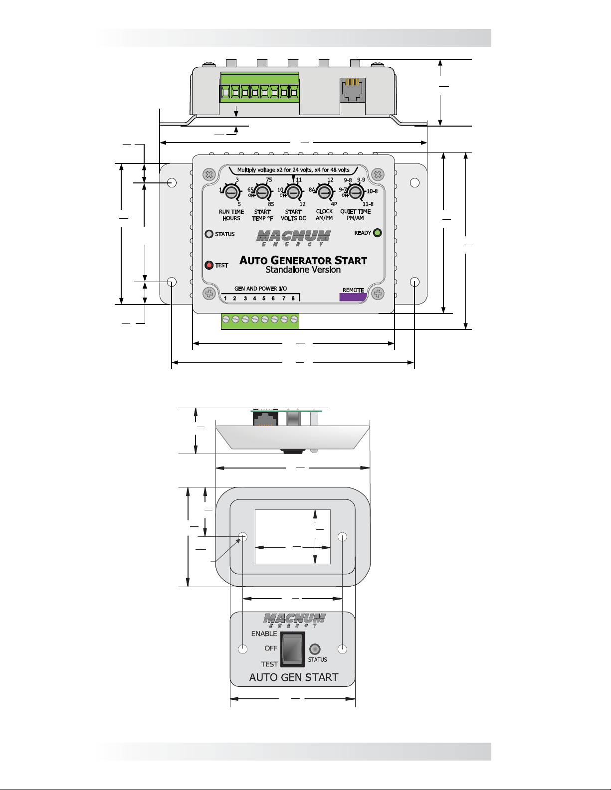
Figure 2-2, Controller Dimensions ........................................................7
Figure 2-3, Remote Dimensions ...........................................................7
Figure 2-4, Communication Cable Connection ........................................8
Figure 2-5, Communication Cable (Data Type) .......................................8
Figure 2-6, Generator Run Sense Options ........................................... 10
Figure 2-7, Wiring to the AGS Controller’s Terminal Block ...................... 12
Figure 2-8,
Figure 2-9, Two-wire Start Type Generators ........................................ 14
Figure 2-10, Three-wire Momentary Type Generators ........................... 15
Figure 2-11, Three-wire Maintain Type Generators ...............................16
Figure 3-1, Inside the AGS Controller .................................................17
Figure 3-2, DC Voltage Settings ......................................................... 17
Figure 3-3, External Settings ............................................................. 19
Figure 4-1, Controller Front Panel Controls and Indicators ..................... 22
Figure 4-2, Remote Switch Controls and Indicators .............................. 23
Warning Label ................................................................. 13
List of Tables
Table 3-1, GEN TYPE Settings ............................................................ 18
Table 3-2, ME-AGS-S Default Settings ................................................ 19
Table 6-1, Troubleshooting Guide ....................................................... 25
© 2013 Magnum Energy, Inc. ii
Page 4

Introduction
1.0 Introduction
The Automatic Generator Start – Standalone version (ME-AGS-S) from Mag-
num Energy is designed as a standalone device. It will automatically start your
generator based on low battery voltage and/or a high temperature condition.
Info: This manual is for the ME-AGS-S with revision 5.0 or higher; see
Figure 3-1 on page 17 for info on how to locate your revision level.
Info: If you are using a Magnum inverter/charger (provided with a
network port) and a ME-RC or ME-ARC remote, use the ME-AGS-N
(AGS – Network version) for full network capability of the AGS system.
This AGS is used to continuously monitor your battery system and/or the
surrounding area temperature, and to automatically start the generator when
the battery requires charging and/or power is needed to run an air conditioner
to cool down the surrounding area.
The temperature turn-on feature is useful in many applications. For example,
if you have an RV (recreational vehicle) coach in a hot environment, the AGS
monitors the coach temperature and turns on the generator to power the air
conditioner. This allows you to leave pets and precious items in your coach
while you enjoy a day away golfi ng, touring, or just sightseeing—all the while
knowing your coach will stay cool and comfortable. Even if you don’t have pets,
there’s nothing better than returning to a nice cool coach while dry camping
in hot weather. Plus, no more worrying about dead batteries.
The AGS system includes a controller with on-board adjustments and interfaces with a user-friendly remote control switch. The controller provides the
wiring interface for the battery bank and generator start/stop circuits. It has
adjustments for setting the generator’s run time, high temperature start,
and low battery voltage start; and if needed, the “Clock” and “Quiet Time”
adjustments can be set to comply with RV park and rest area nighttime low
noise requirements. The remote switch allows testing and activating the AGS
system and provides a LED indicator to display AGS system status information.
This AGS is compatible with most AC or DC generators with either two-wire or
three-wire start controls; such as Onan, Power T ech, Gener ac, Martin, Kohler,
Honda, Westerbeke, Y amaha, and many others. A list of gener ators that have
been successfully used with the AGS (along with their respective wiring diagrams) can be found at: www.magnumenergy.com/GenWiringDiagrams.htm
The standalone AGS is equipped with the following features:
• Compatible with 12, 24, or 48-volt systems
• Easily adjustable settings for run-time, low voltage, and high temperature start
• Quiet Time setting available to prevent generator oper ation during nighttime hours
• Compatible with any inverter/charger-based system
• Compatible with most AC or DC generators with either two-wire or threewire start controls
• TEST switch provides immediate confi rmation of installation wiring
• Removable 8-port terminal block – for easy wiring and power-down
• Front panel LED indicators for generator start/stop status and generator faults
1 © 2013 Magnum Energy, Inc.
Page 5
Introduction
1.1 ME-AGS-S Components/Features
The ME-AGS-S is equipped with the following components and features:
• AGS Remote Switch • Communications Cable • AGS-S Controller
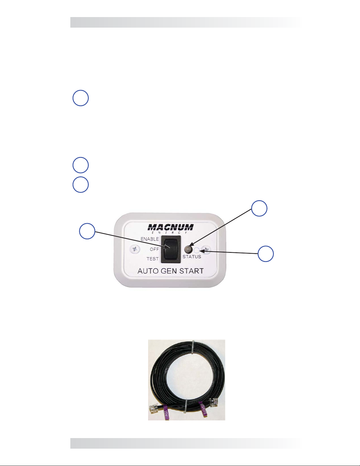
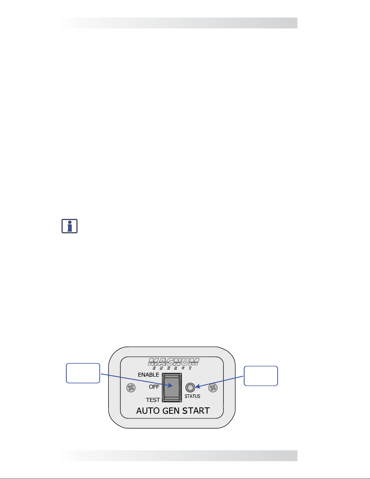
1.1.1 AGS Remote Switch
The AGS Remote Switch is the user interface display and connects to the
AGS controller through the communications cable.
Selector Switch – a switch that allows the AGS system to be
1
enabled for automatic generator operation and tested for correct
wiring.
• ENABLE – activates the AGS to monitor voltage and/or temperature to determine when to automatically start the generator.
• OFF – disables the AGS generator start/stop functions.
• TEST – initiates an automatic generator start/stop sequence for
testing generator wiring and operation.
STATUS Indicator – this bi-color (green or red) LED indicator
2
illuminates to provide information on AGS operation.
Temperature Sensor (internal) – location of the internal sensor
3
used to start the generator based on high temperature.
2
STATUS
1
Indicator
Selector
Switch
3
Temperature
Sensor (internal)
Figure 1-1, ME-AGS-S Remote Switch Features
1.1.2 AGS Communication Cable
A six-conductor, 25-foot cable used to carry power and data between the
remote and the controller.
Figure 1-2, ME-AGS-S Communications Cable
© 2013 Magnum Energy, Inc. 2
Page 6
Introduction
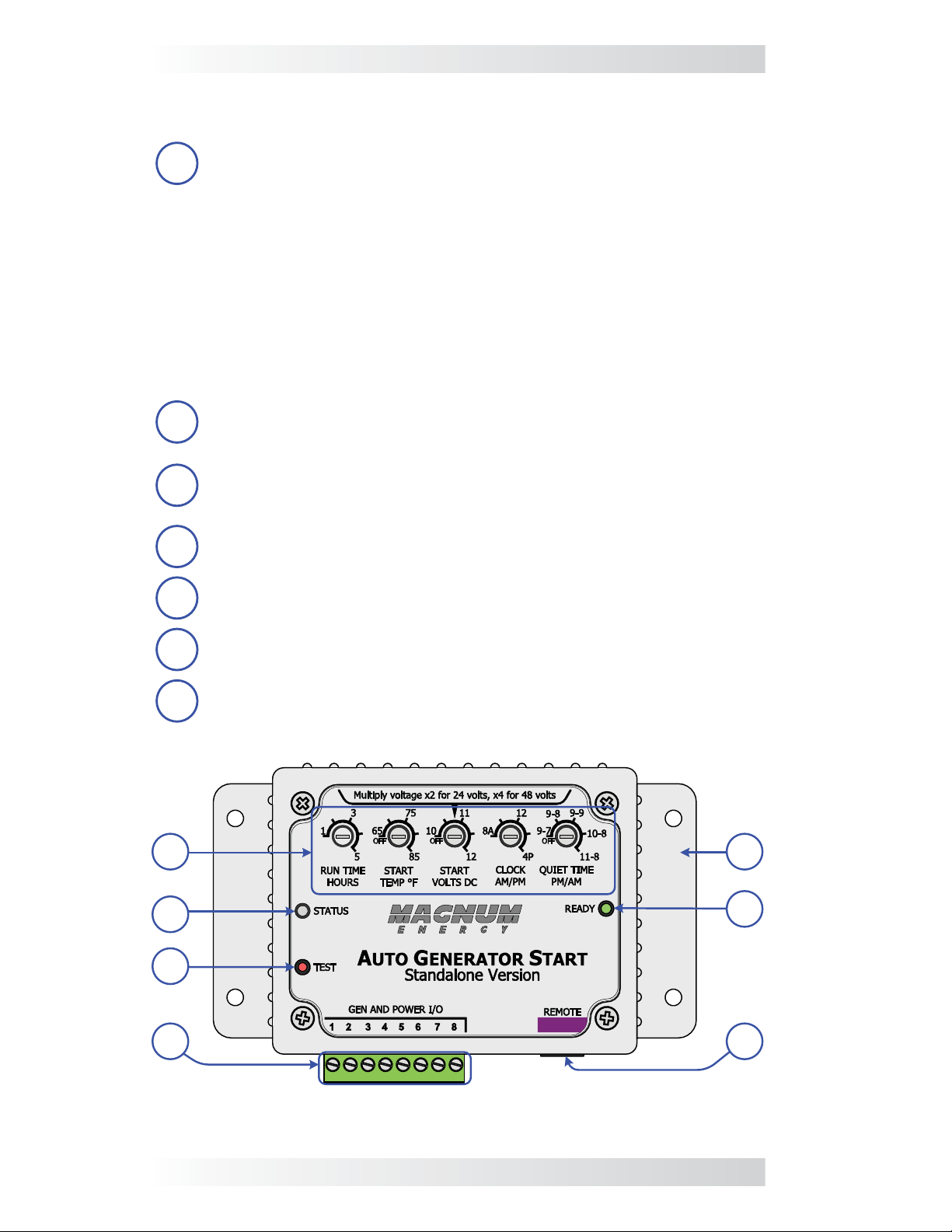
1.1.3 AGS Controller
The controller provides adjustments and the generator’s wiring connections.
AGS Adjustments (x5) – The thumb wheel adjustments allow the
1
AGS to be confi gured to your specifi c system preferences.
• RUN TIME HOURS – determines the length of time the generator
runs once the generator has automatically started.
• START TEMP °F – allows you to
value that causes the generator to automatically start.
• START VOLTS DC – allows you to enable and set a low battery
voltage value that causes the generator to automatically start.
• CLOCK AM/PM – determines the correct time, which in turn
allows the Quiet Time feature to function correctly.
• QUIET TIME PM/AM – used to prevent the generator from
starting during specifi c hours.
STATUS Indicator – this bi-color (green or red) LED indicator
2
illuminates to provide information on AGS operation.
TEST Switch – a momentary pushbutton switch that allows the
AGS system to be tested for correct wiring and generator start/stop
3
operation.
enable and set a high temperature
2
3
Wiring Terminal Block – this 8-port friction-fi t connector powers
4
the AGS and connects the generator’s start/stop and run sense wires.
Mounting Flange – used to secure the inverter to a shelf or wall.
5
READY Indicator – this green LED indicator illuminates to indicate
6
that the AGS is powered and the remote switch is connected.
REMOTE Connection Port (purple label) – a RJ12 port which
7
provides the connection point for the remote switch.
51
6
4
Figure 1-3, ME-AGS-S Controller Features
3 © 2013 Magnum Energy, Inc.
7
Page 7
Installation
2.0 Installation
Installing the ME-AGS-S is a simple process. Before installing, read this entire
section to familiarize yourself with all aspects of the installation; then, you
can thoroughly plan the details to ensure the overall system requirements
are accomplished. To assist you in planning and designing your installation,
review the basic system diagram shown in Figure 2-1.
WARNING: The ME-AGS-S is not an ignition-protection rated device
and should not be installed in any location that requires ignitionprotected equipment. To prevent fi re or explosion, do not install
the Auto Gen Start controller in any area with extremely fl ammable
liquids like gasoline or propane; or, in an area that contains connections between components of a fuel system.
CAUTION: Installations should be performed by qualifi ed personnel,
such as a licensed or certifi ed electrician. It is the installer’s respon-
sibility to determine which safety codes apply and to ensure that all
applicable installation requirements are followed. Applicable installation codes vary depending on the specifi c location and application.
CAUTION: Review the “Important Product Safety Information” on
the front inside cover page before any installation.
2.1 Installation Requirements
Review the following requirements before installing this device:
• For the AGS to automatically start and stop the generator properly, the
generator must include an electric start and an automatic choke. To
prevent generator damage and obtain reliable operation, use generator
models designed for unattended operation. These models should also
be equipped with remote operation connections and have protective
systems that cause the generator to shut down from low oil pressure,
over-temperature, starter lockout, and over-crank conditions.
• The ME-AGS-S controller is connected to the switch by a 25’ communica-
tions cable. Before installing the ME-AGS-S and connecting any wires,
determine: 1) the communications cable route throughout the home or
vehicle/boat from the controller to the switch, 2) the start/stop signal
wire route from the AGS controller to the generator, and 3) the wire route
from the AGS controller to the monitored battery bank.
Info: Two pigtail adapters (ME-PT1 and ME-PT2) are available to
externally enable the ME-AGS-S to automatically turn the generator on/off through a manually controlled switch or an automatically
controlled switching device. See Appendix A for more information.
• Always check for existing electrical, plumbing, or other areas of potential
damage BEFORE drilling or cutting into walls.
• If installing this device in a boat, RV , or truck, ensure the conductors passing through walls, bulkheads, or other structural members are protected
to minimize insulation damage such as chafi ng—which can be caused by
vibration or constant rubbing.
• Do not mount the AGS controller in a closed battery compartment or in
an area where water or any other liquid can enter the AGS and cause
shorting or corrosion.
• The AGS should be wired to not interfere with your air conditioner controls
or the manual start/stop switches on your generator.
© 2013 Magnum Energy, Inc. 4
Page 8

Installation
Automatic Generator Start (Standalone version)
ME-AGS-S
Remote connection
Generator start/stop wiring
Generator run signal
Battery voltage
Common battery negatives
(Monitored battery and
Generator starting battery)
Monitored Battery Bank Auto-Start Generator
Figure 2-1, ME-AGS-S System Diagram
5 © 2013 Magnum Energy, Inc.
Page 9

Installation
2.2 Required Components and Tools
2.2.1 List of supplied components in the ME-AGS-S:
• ME-AGS-S Owner’s Manual
• AGS controller (with four #8 x 3/4” Phillips mounting screws)
• AGS switch/bezel (with two #6 x 1” Phillips mounting screws)
• 25 ft communications cable
2.2.2 List of other required equipment and materials:
• 16 to 12 AWG wire for connecting the ME-AGS-S to the gener ator start/
stop circuit and to the battery bank
• In-line fuse holders (with 5-amp DC fuse)
2.2.3 Tools that may be required to install the ME-AGS-S:
• Phillips screwdriver (#2)
• Flat-blade screwdrivers
(1/4” and 1/8” blades)
• Wire stripper
• Cut-out tool (knife/saw)
• Drill bits (7/64” & 1/8”)
• Drill
• Level
• Pencil
2.3 Mounting Procedure
2.3.1 Mounting the AGS Controller
1. Select a location that is clean, dry, and protected from extreme
temperatures to mount the controller
controller is mounted within easy access to the generator’s remote
switch wiring. Refer to Figure 2-2 for the controller’s dimensions.
Info: The controller/switch can be mounted in any direction. However,
allow ample room to
to view the LEDs for operational status and troubleshooting.
2. Remove the green 8-pin friction fi t connector from the controller by
pulling it straight out. Wait to plug this 8-pin connector back into the
AGS controller until after the installation is completed and the AGS
functional tests are performed in Section 3.3.
3. Mount the AGS controller using the four #8 x 3/4” screws provided.
2.3.2 Mounting the AGS Remote Switch
1. Select a location that is
extreme temperatures to mount the
access the switch and the
convenient,
. Wiring is much easier if the
adjustment dials, and
clean, dry, and protected from
remote switch.
Info: The temp sensor used to activate the temperature turn-on
feature is located on the back of the AGS switch. If using the temperature turn-on feature, the switch must be placed where the room
temperatures can be accurately determined by the sensor. DO NOT
mount the switch near window drafts, or heating and air conditioning
ducts, and avoid mounting it on exterior walls.
2. Cut a hole for the switch. See Figure 2-3 for switch and cutout dimensions.
3. Plug the communications cable into the RJ12 connector on the back of
the AGS switch (Section 2.4), and then feed the communication cable
(6-conductor data cable) through the opening and route it to the AGS.
Info: Use care in routing the cable to ensure the cable does not
become pinched or cut by rough or sharp edges. Leave enough slack
to allow movement of the cable once the installation is complete.
4. Mount the switch with its bezel to the wall using the two #6 x 1” screws
provided.
© 2013 Magnum Energy, Inc. 6
Page 10
9
16
3
”
7
8
4
”
3
16
2
”
1
16
4
”
3
8
”
3
8
5
”
1
4
3
”
7
16
”
2
”
5
16
1
”
3
16
”
cutout
"
drill
bit
2
"
1
"
1
"
1
"
3
"
1
"
2
"
2
"
1
8
7
16
1
4
5
16
7
64
1
8
3
4
5
8
3
16
Installation
Figure 2-2, Controller Dimensions
Remote
side
Remote
Bezel
Remote
face-plate
Figure 2-3, Remote Dimensions
7 © 2013 Magnum Energy, Inc.
Page 11

Installation
123
4
56
123
4
56
white
blue
TAB
TAB
2.4 Connecting the Communication Cable
After connecting one end of the communication cable to the back of the
AGS remote switch, connect the other end of the cable to the REMOTE port
(purple label) on the AGS controller (see Figure 2-4).
Info: The communication cable is a 6-conductor, fl at, data stan-
dard with RJ12 (6-position/6-wire) connectors on each end
(see Figure 2-5).
Info: The 25’ communications cable may be extended to a maximum
of 250 feet if needed.
ME-AGS-S Controller
Communications
Cable
Remote Switch
(backside)
Figure 2-4, Communication Cable Connection
2.4.1 Communication Cable
The 6-conductor communications cable has a RJ12 (6-position/6-wire) connector on each end and is wired as a data type cable. This means that when
the RJ12 connectors are held side by side with both of the connector tabs
facing the same way, the color of the conductors in each connector is the
same from top to bottom (as shown in Figure 2-5).
same colors
from top
to bottom
(tabs facing
toward you)
Figure 2-5, Communication Cable (Data Type)
© 2013 Magnum Energy, Inc. 8
Page 12
Installation
2.5 ME-AGS-S Terminal Block Wiring
The controller should now be mounted. For the following steps, refer to Figure
2-7 for reference when wiring the generator to the controller’s terminal block:
1. Unplug the green 8-port friction-fi t terminal block from the controller
by pulling it straight out. Ensure the openings are unscrewed enough to
allow the wires to be inserted.
CAUTION: DO NOT plug in the 8-port terminal block. After all
the wiring to the controller is complete and all the settings have been
confi gured, a power-up test will be performed Section 4: Operation.
DO NOT plug in the 8-port terminal block until then.
CAUTION: A fuse rated at 5 amps or less must be used to protect
all power circuits (except for ground connections) connected to the
AGS controller. Ensure the fuse is correctly rated for the wire size
used. Refer to national and local codes for rating and type. Normally ,
a minimum #16 AWG wire is required to use a 5-amp fuse.
Info: The green 8-port terminal block accepts CU/AL conductors from
2
#30 to #12 AWG (0.05 to 3.3 mm
).
2.5.1 Power Connections (Terminals 3 and 4)
2. Connect a wire (black) from the monitored battery bank’s negative terminal to Terminal #4 on the 8-port terminal block.
3. Connect a wire (red) with a 5-amp, in-line fuse from the monitored battery bank’s positive terminal to T erminal #3 on the 8-port terminal block.
2.5.2 Generator Run Sense Connection (Terminal 2)
T erminal #2 on the 8-port terminal block is used as a generator run sense (i.e. ,
switched B+ or a positive battery signal from the hour meter or gen running
light). This run sense voltage is used to determine that the generator is running
and to prevent another starter crank while the generator is already running.
Info: The run sense signal from the generator to Terminal #2 (positive) and Terminal #4 (negative) must be between 10-40 VDC and
only while the generator is running.
4. Connect a wire (preferably not black or red) from the generator’s run
sense output to Terminal #2 on the 8-port terminal block.
5. Connect the negative terminal of the monitored battery bank to Terminal
#4 (power negative) on the 8-port terminal block. Ensure the negative
terminal on the generator battery is referenced/connected to the negative terminal on the monitored battery.
Info: The negative side of the run sense signal from the generator
must be in common with the negative side of the monitored battery
bank. This ensures that the positive battery voltage (to T erminal #3)
and the positive run sense voltage (to Terminal #2) have a common
negative reference (to Terminal #4) and are correctly measured by
the ME-AGS-S.
9 © 2013 Magnum Energy, Inc.
Page 13
Installation
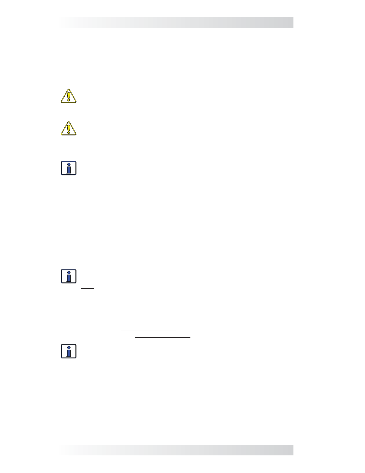
What if my generator does not have a run sense output? If your gen-
erator is not equipped with a generator run sense output, review Figure 2-6
for alternative options.
Option 1 – Tap into the positive side of the generator’s hour meter or running light;
Option 1 - Tap into the positive side of the generator’s hour meter or running light; ensure
ensure the voltage is only 10-40 VDC while the generator is running.
the voltage is 10 to 40 VDC only while the generator is running.
AGS Terminal Block Ports:
1 2 3 4 567 8
negative
run sense
DC Fuse
(5A max)
Option 2 – Use a 120 VAC to 12 VDC step-down transformer (normally used to charge
Option 2 - Use a 120VAC to 12VDC step-down transformer (normally used to charge power
power equipment batteries) and plug into the generator’s 120 VAC output. The step-
equipment batteries) and plug into the generator’s 120VAC output. The step-down
down transformer provides 12 VDC output only while the generator is running.
transformer provides 12 VDC output only while the generator is running.
Inside Generator
OR
Generator
Hour Meter
Generator
Battery
0123
Generator
Running Lamp
On Generator
AGS Terminal Block Ports:
1 2 3 4 567 8
120VAC Outlet
120VAC IN
negative
run sense
DC Fuse
(5A max)
Option 3 – Use an external 120 VAC coiled relay to bring the generator’ s battery voltage
Option 3 – Use an external 120VAC coiled relay to bring the generator's battery voltage to
to the AGS run sense port (AGS Terminal Block Port #2) only while the generator is
the AGS run sense port (AGS Terminal Block Port #2) only while the generator is running.
running. The generator’s battery voltage must be 10-40 VDC.
The generator’s battery voltage must be 10 to 40 VDC.
AGS Terminal Block Ports:
1 2 3 4 567 8
negative
run sense
NO
NC
COM
DC Fuse
(5A max)
NEUHOT
Inside Generator
12VDC OUT
TRANSFORMER
Generator
Battery
On Generator
120VAC Outlet
120VAC Coil Relay
Figure 2-6, Generator Run Sense Options
© 2013 Magnum Energy, Inc. 10
Page 14

Installation
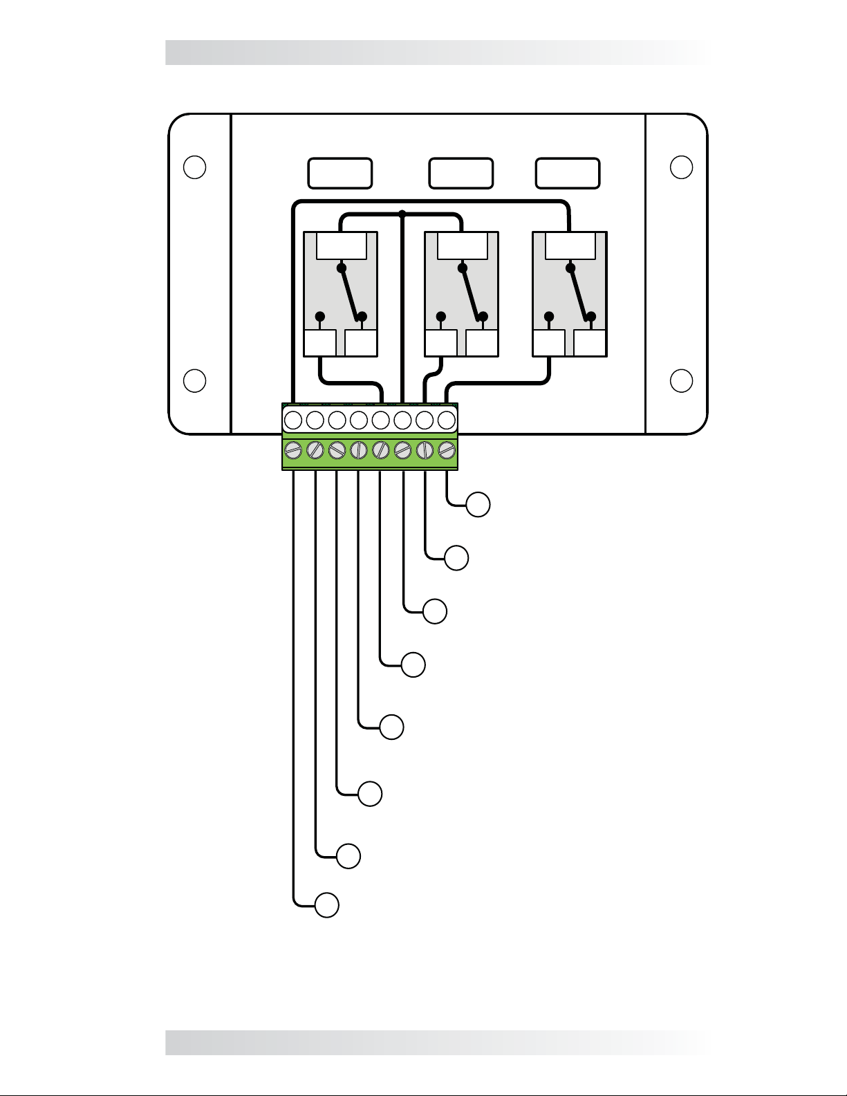
2.5.3 Gen Start/Stop Connections (Terminals 1, 5, 6, 7, & 8)
This section details the control relays inside the AGS controller and provides
information on wiring these relays to the generator’s start/stop circuit. You
must identify the generator’s start and stop wiring requirements to determine
how many relays you require, the amount of wires you connect, and in what
combination.
If the generator is equipped with a remote control terminal or connector,
the connections to the AGS control relays are made much easier if the
generator‘s optional remote control panel is purchased. Connecting to the
generator’s remote panel also eliminates the need to make connections
inside the generator (and possibly violating the generator’s warranty).
The AGS controller provides three control relays (RY1, RY2, and RY3) to
operate the autostart/autostop functions of your generator. These relays are
dry contacts (does not provide any voltage or current) and operate only as
switches that turn on and off low amperage devices. They are not intended
to directly provide power to starter motors or ignition systems, rather they
are used to send a signal to operate the coil of another higher amperage
device which does the actual switching of power.
CAUTION: A fuse rated at 5 amps or less must be used to protect
each of the relays. The warranty does not cover damage to these
relays. Fuses should be located as close as possible to the generator
connection. A fuse must be used even if the circuit is providing only
a “dry contact” or “ground” connection—it will prevent damage if the
connection is miswired or damaged.
Info: To set the generator type—which determines the operation of
the AGS relays—see “GEN TYPE Setting” in the Setup section.
Info: Due to the different generator types and the various starting/
stopping wiring confi gurations used by generator manufacturers,
detailed wiring instructions are not provided in this manual. Please
refer back to your generator’s documentation for wiring details.
Info: For more information and to view diagrams on connecting
the AGS to the start/stop circuit on many generators, refer to the
“Generator Wiring Diagrams” section at www.magnumenergy.com.
Depending on your generator’s start and stop wiring requirements, you may
only need to use one relay (RY1) for fully automatic two-wire generators; two
relays (RY1 and RY2) for 3-wire generators; or all three relays (RY1, RY2,
RY3) for generators that require an independent bypass or preheat circuit.
The connection points to each relay is as follows (see Figure 2-7):
• Relay 1 (RY1) and Relay 2 (RY2)
Terminal #5: This is the Normally Open (N.O.) position of the RY1 relay.
Terminal #6: This is the Common (COM) position of both Relay 1 (RY1) and
Relay 2 (RY2).
Terminal #7: This is the Normally Open (N.O.) position of Relay 2 (RY2).
• Relay 3 (RY3)
Terminal #1: This is the Normally Open (N.O.) position of Relay 3 (RY3).
Terminal #8: This is the Common (COM) position of Relay 3 (RY3).
11 © 2013 Magnum Energy, Inc.
Page 15
Installation
Relays Inside the AGS controller
1
RY1
COM
NO
2 3 4
5 6
RY2 RY3
COM
NONC
8
7
8
Normally Open (N.O.)
7
contact on Relay 2 (RY2)
NONC
Normally Open (N.O.)
contact on Relay 3 (RY3)
COM
NC
Common (COM) contact on
6
Relay 1 (RY1) and Relay 2 (RY2)
Normally Open (N.O.) contact
5
on Relay 1 (RY1)
Negative DC voltage input
(negative/ground terminal from
4
monitored battery bank)
Positive DC voltage input
3
[(positive terminal from monitored
battery bank (9-64 VDC)]
Run Sense input (10 - 40 volts DC only
2
when gen is running)
Common (COM) contact on Relay 3 (RY3)
1
Figure 2-7, Wiring to the AGS Controller’s Terminal Block
© 2013 Magnum Energy, Inc. 12
Page 16

Installation
2.6 Warning Label
It might be falsely assumed that it is safe to perform maintenance on the
generator or the electrical panel because the generator is off. However, the
AGS system can automatically turn on the generator and power the panel.
Two warning labels (Figure 2-8) are provided to inform all personnel that an
Automatic Generator Starting device is installed in your electrical system.
Place one label in a clearly visible location at the generator and the other
label at the electrical panel that is being powered by the generator.
WARNING: T o prevent harm to servicing personnel, ensure the gen-
erator and AGS are properly disabled (i.e. , remove the starting battery
from the generator and remove all power to the AGS by u
the green 8-port friction-fi t terminal block from the controller
performing maintenance on the generator or electrical panel.
nplugging
) prior to
WARNING
This electrical system is equipped with an
Automatic Generator Starting (AGS) device and/or
an inverter. Disconnect all AC and DC power to the
AGS and/or inverter before performing any service
to the electrical system. Failure to do so can result
in shock causing serious injury or death.
PN: 62-0002 Rev A
Figure 2-8, Warning Label
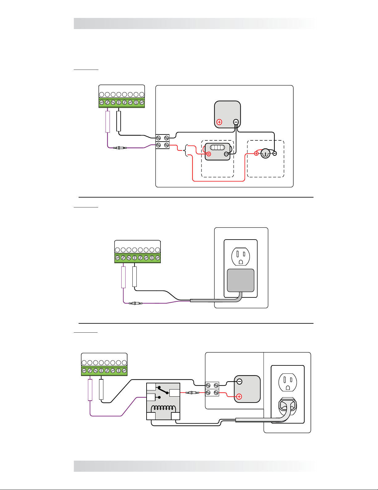
2.7 Common ME-AGS-S Generator Wiring Diagrams
The most common generator starting/run/stop circuits can be divided into
three major types: two-wire, three-wire “momentary”, or three-wire “maintain” . The following generator wiring diagr ams are provided to give examples
of these generator types.
Info: The term “three-wire” refers to the minimum number of wires
required to control the starter motor and to run the generator—more
than three wires may actually be needed.
Shown in Figure 2-9, the “two-wire” generator types integrate the control
circuits for start-up, running and stopping. The generator starts and runs when
two “control” wires are connected, and stops when they are disconnected.
Shown in Figure 2-10, the “three-wire momentary” generator types use a
three-position momentary type switch that controls their operation. To start
the generator, the switch is momentarily held to the START position. This
energizes the ignition system and cranks the starter motor. Once the engine
has started, the START switch is released and it returns to a center position
(i.e., “momentary” run control). To shut down the generator, the switch is
held to the STOP position until the engine dies. Once the switch is released,
it returns to the center position (i.e., “momentary” stop control).
Shown in Figure 2-11, the “three-wire maintain” generator types use an automotive type starting circuit. Operating a switch that is fi rst turned to a RUN
position and then momentarily held to a START position to start the generator.
Once the engine has started, the switch is released and it returns to the RUN
position (i.e., “maintain” run control). To shut down the generator, the switch
is moved to the OFF position (i.e., “maintain” stop control).
13 © 2013 Magnum Energy, Inc.
Page 17

INSIDE
INSIDE
Installation
INPUT DC
VOLTAGE JUMPER
- set to monitored
battery bank voltage
12/24/48V
(on 24V setting)
GEN TYPE
4321
(2-Wire
Maintain
ON
Mode)
≤5
amp
fuse
battery bank
(12V/24V/48V)
GEN AND POWER I/O
Relay 1
(Terminals 5 & 6)
Relay 2
(Terminals 6 & 7)
Relay 3
(Terminals 1 & 8)
R2 (Relay 2) Time
Delay time
Relay timing for GEN TYPE: 2-Wire Maintain Mode
≤5
amp
fuse
Monitored
≤5
amp
fuse
Ground
OFF
Delay
R2
Timing Information
10 sec.
4 sec.
Inside Generator
Run / Off
Switch
0 1 2 3
Gen
Battery
RUN TIME HOURS
RUN
Time between start attempts
Total start attempts 4
Hour Meter
Gen
OFF
2 min.
Figure 2-9, Two-wire Start Type Generators
© 2013 Magnum Energy, Inc. 14
Page 18

Installation
≤5
amp
fuse
≤5
amp
fuse
≤5
amp
fuse
INSIDE
INSIDE
Inside Generator
INPUT DC
VOLTAGE JUMPER
- set to monitored
battery bank voltage
12/24/48V
(on 24V setting)
4321
GEN TYPE
(5-wire mode)
ON
PREHEAT
≤5
amp
fuse
Monitored
battery bank
(12V/24V/48V)
GEN AND POWER I/O
Relay 1
(Terminals 5 & 6)
Relay 2
(Terminals 6 & 7)
Relay 3
(Terminals 1 & 8)
STOP Time
START Time
PREHEAT Time 25 sec.
Start Delay Time 14 sec
Relay timing for GEN TYPE: 5-wire Mode
0 1 2 3
Gen
Hour Meter
Start
STOP
Delay
Delay
PREHEAT
Timing Information
10 sec.
10 sec.
.
Gen
Battery
START
RUN TIME
HOURS
Preheat delay time
Time between start attempts
Total start attempts
STOP
START
STOP
4 sec.
2 minutes
4
Figure 2-10, Three-wire Momentary Type Generators
15 © 2013 Magnum Energy, Inc.
Page 19

INSIDE
INSIDE
Installation
INPUT DC
VOLTAGE JUMPER
- set to monitored
battery bank voltage
12/24/48V
(on 24V setting)
4321
GEN TYPE
(Portable
ON
Mode)
≤5
amp
fuse
≤5
amp
fuse
Monitored
battery bank
(12V/24V/48V)
amp
fuse
GEN AND POWER I/O
Relay 1
(Terminals 5 & 6)
Relay 2
(Terminals 6 & 7)
Relay 3
(Terminals 1 & 8)
START Time
T1 Time
Delay time 2 sec.
Relay timing for GEN TYPE: Portable Mode
≤5
Inside Generator
0 1 2 3
Gen
Hour Meter
Delay
START
Delay
Timing Information
10 sec.
5 sec.
Time between start attempts
19
50
30
Gen
Battery
19
50
30
OFF
RUN
START
RUN
RUN TIME HOURS
T1
Total start attempts 4
Switch
30 50 19
OFF
2 min.
Figure 2-11, Three-wire Maintain Type Generators
© 2013 Magnum Energy, Inc. 16
Page 20

Setup
3.0 Setup
This section provides information on AGS settings and shows you how to
adjust these settings.
3.1 Internal Settings
On the AGS controller, unscrew the four top screws and remove the plastic
cover to access an input DC voltage jumper and a 4-position DIP (Dual In-line
Package) switch. The INPUT DC VOLTAGE jumper position determines the controller’s DC operating voltage. The DIP switch confi guration is used to select the
GEN TYPE which determines how the internal relays operate to automatically
start and stop the generator.
INPUT DC
VOLTAGE
Setting
12/24/48V
(Default: 12V)
4321
GEN
TYPE
Setting
(Default: QD mode)
Revision
Label
RY1 RY2 RY3
Rev
##
ON
4321
12/24/48V
2
134
ON
Figure 3-1, Inside the AGS Controller
INPUT DC VOLTAGE Setting: The INPUT DC VOLTAGE setting is determined
by connecting two small pins with a small black plastic box (i.e. , jumper). This
setting can be confi gured for 12, 24, or 48 VDC operation, which is determined
by the nominal DC voltage connected to Terminals 3 and 4 on the AGS.
• For 12-volt DC operation, position the jumper on the bottom two pins.
• For 24-volt DC operation, position the jumper on the middle two pins.
• For 48-volt DC operation, position the jumper on the top two pins.
12 VDC Operation
(jumper on bottom
two pins)
24 VDC Operation
(jumper on middle
two pins)
48 VDC Operation
(jumper on top
two pins)
**default setting**
Figure 3-2, DC Voltage Settings
GEN TYPE Setting: The GEN TYPE setting is determined by a DIP switch,
which is actually 4 small switches that can be turned to the ON or OFF
position. The position of each of these 4 small switches is used to determine
the open and close timing sequence for the three internal AGS relays (RY1,
RY2 and RY3). The multiple positions of the DIP switch allow a wide range of
generator start/stop circuit confi gurations.
After determining the appropriate start/stop timing sequence for your
generator, use Table 3-1 to determine and set the correct GEN TYPE setting
for your generator’s start/stop requirements.
For examples and assistance in viewing which GEN TYPE setting is used for
specific generators, view the “ Generator Wiring Diagrams” under the Service
and Support area at www.magnumenergy.com.
17 © 2013 Magnum Energy, Inc.
Page 21

Table 3-1, GEN TYPE Settings
Setup
GEN
TYPE
ON
QD Mode
(default)
ON
3-Wire
Mode
ON
Portable
Mode
ON
2-Wire
Momentary
Mode
ON
2-Wire
Maintain
Mode
ON
5-Wire
Mode
Relay Timing/Operation (RY1/RY2/RY3)
RY1
4321
(N.O.)
RY2
(N.O
RY3
N.O.)
(
.)
T3
T2
Generator: Quiet Diesel (
RY1
4321
(N.O.)
T1
T3
T2
T1
T2
T1
T1
T3
RY2
(N.O.)
RY3
(N.O.)
Generators: Marquis, Emerald, and Microquiet (Onan); Quiet Pack
Series (Generac).
1
RY
4321
(N.O.)
RY2
(N.O.)
RY3
(N.O.)
Generator: EM Series with remote control (Honda).
RY1
4321
(N.O.)
RY2
(N.O.)
RY3
(N.O.)
Generator: PT-ECU-63 controller with 2-wires (Powertech).
RY1
4321
(N.O.)
RY2
(N.O.)
RY3
(N.O.)
Generators: RMY Series (Kohler); DynaGen Controllers
RY1
4321
(N.O.)
RY2
(N.O.)
RY3
(N.O.)
Generators: BTDA / BEG (Westerbeke), 205-DS (Martin Diesel), NL-
673 (Northern Lights)
T2
T1
T1
Onan).
T2
RUN TIME
T1
T4
RUN TIME
T1
RUN TIME
RUN TIME
RUN TIME
T3
RUN TIME
T3
T3
T2
T1
Time
Period
T1 =
20 sec.
T2 =
4 sec.
T3 =
10 sec.
T1 =
5 sec.
T2 =
2 sec.
T3 =
10 sec.
T1 =
2 sec.
T2 =
10 sec.
T3 =
5 sec.
T1 =
2 sec.
T2 =
10 sec.
T1 =
4 sec.
T2 =
10 sec.
T1 =
10 sec.
T2 =
14 sec.
T3 =
4 sec.
T4 =
25 sec.
© 2013 Magnum Energy, Inc. 18
Page 22

Setup
3.2 External Settings
The generator run time, temperature, and voltage settings come pre-set
directly from the factory. For the majority of customers, the factory default
settings as shown in Table 3-2 are appropriate. If you need to make changes
to the factory settings, you can do so by rotating the knobs on the front panel
of the AGS controller either clockwise or counterclockwise (see Figure 3-3).
Table 3-2, ME-AGS-S Default Settings
Adjustable Settings Factory Default Values
RUN TIME HOURS 2 (Hours)
START TEMP °F OFF (disabled)
START VOLTS DC 11 (Volts DC)
SETTINGS
EXTERNAL
CLOCK AM/PM 8A (8 AM)
QUIET TIME PM/AM OFF (disabled)
INPUT DC VOLTAGE 12 Volts (bottom two pins)
SETTINGS
INTERNAL
RUN TIME
HOURS
setting
GEN TYPE QD Mode (all 4 switches off)
START
TEMP °F
setting
START
VOLTS DC
setting
CLOCK
AM/PM
setting
QUIET TIME
PM/AM
setting
Figure 3-3, External Settings
RUN TIME HOURS: This setting determines the length of time the generator
runs once started. The generator starts because the battery voltage has
fallen to the START VOLTS DC setting for at least two continuous minutes;
or, the temperature around the remote switch has risen to the START TEMP
°F setting. The run time can be set from 1-5 hours. To change this setting,
slowly rotate the knob marked RUN TIME HOURS clockwise to increase
generator run time or counterclockwise to decrease the generator run time.
19 © 2013 Magnum Energy, Inc.
Page 23

Setup
START TEMP °F:
value that causes the generator to automatically start.
around the AGS switch increases to the START TEMP °F temperature setting,
the generator automatically starts and runs based on the
setting. The AGS attempts to start the generator immediately once the
temperature rises to this setting. The
from 65°F-85°F
adjustment knob is turned fully counterclockwise to the OFF position.
Why would I use the temperature start feature? For RV users, you could
set the air conditioner to turn on (comes on when power is provided by the
generator) and leave the RV. The generator will automatically start when
the temperature rises to your AGS temperature start setting, providing
power to the air conditioner; thereby , turning it on. This allows you to leave
pets and precious items in your coach while dry camping in hot weather;
knowing your RV will stay cool and comfortable - plus, while the generator
is on, the house batteries are being charged.
START VOLTS DC: This setting allows you to enable and set a battery
voltage value that causes the generator to automatically start. When the
battery voltage decreases to or below this setting for two continuous minutes,
the generator automatically starts and runs based on the RUN TIME HOURS
setting
jumper), 20-24 VDC (for 24 VDC jumper), or 40-48 VDC (48 VDC jumper).
If the DC voltage start feature is not needed, turn the adjustment knob fully
counterclockwise to the OFF position.
. The voltage start setting is adjustable from 10-12 VDC (12 VDC
This setting allows you to enable and adjust a temperature
When the temperature
RUN TIME HOURS
temperature start setting is adjustable
.
If the temperature start feature is not needed, ensure the
Info: This system is capable of 12 VDC, 24 VDC, or 48 VDC operation. For 24 VDC applications, double the value indicated on the cover
(i.e., 11 VDC equals 22 VDC) and for 48 VDC applications, multiply
the indicated value by four (i.e., 11 VDC equals 44 VDC).
CLOCK AM/PM: This setting is used to set the internal clock of the AGS.
The internal clock of the AGS must be set to the correct time in order for the
Quiet Time feature to function appropriately. If the Quiet Time feature is not
used, this clock setting is not required to be adjusted.
To set or change the clock, ensure the current time of day is between the
hours of 8 AM and 4 PM; then, slowly rotate the knob marked CLOCK AM/PM
clockwise to increase the time or counterclockwise to decrease the time. Once
set, the clock will continue to keep time. However, the clock must be reset if
the controller loses power, or when you change time zones.
QUIET TIME PM/AM: This setting is used to prevent the generator from
starting during specifi c hours of the evening (PM) and early morning (AM). It
is adjustable for fi ve pre-selected time ranges.
To set Quiet Time, turn the dial either counterclockwise or clockwise to the
hours required: 9-7 (9 PM to 7 AM), 9-8 (9 PM to 8 AM), 9-9 (9 PM to 9 AM),
10-8 (10 PM to 8 AM), or 11-8 (11 PM to 8 AM). The program only needs
to be set once. If the Quiet Time feature is not needed, turn the dial fully
counter-clockwise to the OFF position.
Info: If the generator is running when the Quiet Time evening hour
(PM) is reached, it automatically stops and does not automatically
start until after the Quiet Time morning hour (AM) has passed.
© 2013 Magnum Energy, Inc. 20
Page 24

Setup
3.3 AGS Functional Tests
After all electrical connections to the AGS, batteries, and generator have been
completed (and prior to connecting the 8-pin green terminal block into the
AGS controller), perform the following tests to verify that the AGS system
is functioning correctly and the wiring from the AGS to generator is correct.
If the AGS fails either test, or the STATUS indicator turns red (indicating a
fault), refer to the Troubleshooting section.
3.3.1 Power-Up Test
1. Ensure the AGS remote switch is set in the OFF position (center position)
and connected to the controller by the communication cable.
2. Before connecting the 8-pin green terminal to the AGS, use a multimeter
to verify the correct polarity and to ensure that the voltage to Terminals
3 (positive) and 4 (negative) is correct according to the position the DC
input jumper (refer to Figure 3-2).
3. Apply power to the AGS by plugging in the green 8-port friction-fi t terminal
block into the controller, and then verify that the green READY indicator
comes on (solid) and the STATUS indicator blinks green once.
Info: The READY indicator blinks when the AGS controller is powered
and the remote switch is not connected to the AGS controller.
3.3.2 Generator Wiring Test
This start/stop test is used to confi rm that all wiring from the generator to
the AGS controller is correct and that the GEN TYPE setting is confi gured
correctly for your generator type.
1. Press and release either:
a) the red TEST switch (on the Controller – see Figure 4-1); or
b) the switch to the TEST position (on the remote switch - see Figure 4-2).
2. After the TEST button/switch is pressed and released, the AGS initiates
an automatic generator start/stop sequence.
3. The STATUS indicator on the controller (and remote switch) begins to
blink green and the generator should start.
4. While the generator is running, view the STATUS indicator and ensure
it turns solid green.
5. The generator should run for approximately 30 seconds before automatically turning off.
Wait for at least 5 minutes to ensure the gener ator remains off and the AGS
does not attempt another start. If this test passes, then activate the AGS
system by setting the remote switch to ENABLE.
If the STATUS indicator shows a fault condition (solid red LED indication),
press the AGS switch to OFF and then back to the ENABLE or TEST position.
If the problem persists, refer to the Troubleshooting section.
Info: The AGS attempts to start the generator 4 times. If after 4
attempts the generator fails to start, the status LED turns red—indicating a fault.
21 © 2013 Magnum Energy, Inc.
Page 25

Operation
4.0 Operation
This section details the front panel controls and the LED indicators on the
AGS controller and remote switch; and explains the operation using these
LED indicators.
4.1 AGS Controller Operation LED Indicators
The front of the controller (Figure 4-1) provides a pushbutton to test the
AGS system operation, and two LED indicators for viewing system operation.
4.1.1 TEST Switch
The TEST switch when pressed and released attempts to turn on the connected generator and allow it to run for at least 30 seconds before turning the
generator off. This start/stop test is used to confi rm that all wiring from the
generator to the AGS is correct and that the GEN TYPE setting is confi gured
correctly for your generator type.
Info: Pushing and releasing the red TEST pushbutton switch enables
the same test as pressing and releasing the momentary TEST position
on the AGS remote switch.
4.1.2 STATUS LED Indicator
Blinking Green – Indicates that the AGS system is initiating a generator
start sequence. This can happen based on two conditions, either: 1) The TEST
switch (on the controller or remote switch) has been pressed and released;
or, 2) The remote switch has been set to the ENABLE position and the START
TEMP °F setting and/or the START VOLTS DC setting has been reached.
Solid Green – Indicates the generator has started successfully and is providing the run sense voltage to Terminals 2 (+) and 4 (-) of the AGS controller.
Solid Red – This is a fault condition to indicate that the generator has not
provided a correct run sense voltage to Terminals 2 (+) and 4 (-) of the AGS
controller after four start attempts.
4.1.3 READY LED Indicator
Solid Green (normal AGS system indication) – Indicates the AGS control-
ler has power and the remote switch is plugged in correctly.
Blinking Green – Indicates that the AGS controller has power , but the remote
switch is not sensed. This means the remote switch is either not connected,
incorrectly connected, is defective, or has an incorrect or defective cable.
STATUS
Indicator
(green/red)
TEST
Switch
READY
Indicator
(green)
Figure 4-1, Controller Front Panel Controls and Indicators
© 2013 Magnum Energy, Inc. 22
Page 26
Operation
4.2 Remote Switch Operation
The AGS remote switch (see Figure 4-2) provides information and enables
you to operate the controller. The remote switch receives its power from the
controller through the communications cable and comes on automatically
when power is applied to the AGS controller.
The remote switch provides an ENABLE position to activate the auto gen
system, an OFF position to turn the auto gen system off, and a momentary
TEST position that allows the auto gen system to be tested remotely. A
STATUS indicator is also included to remotely view system status.
4.2.1 Switch Positions
OFF – When the AGS switch is placed in the OFF position; the STATUS indica-
tor will be off and all AGS generator start functions are disabled.
ENABLE (normal operating position) – When the AGS switch is placed in
the ENABLE position, the AGS system is activated/enabled and now monitors battery voltage and/or temperature to determine when to automatically
start the generator.
TEST – When the AGS switch is pushed to the momentary TEST position, the
AGS initiates an automatic generator start/stop sequence. This test attempts
to turn on the connected generator and allow it to run for at least 30 seconds
before turning the generator off . This start/stop test is used to confi rm that all
wiring from the generator to the AGS is correct and that the AGS is confi gured
correctly for your generator type.
Info: Pushing and releasing the momentary TEST position enables
the same test as pressing and releasing the red TEST pushbutton
switch on the AGS controller.
4.2.2 STATUS LED Indicator
Blinking Green – Indicates that the AGS system is initiating a generator
start sequence. This can happen based on two conditions, either: 1) The TEST
switch (on the controller or remote switch) has been pressed and released;
or, 2) The remote switch has been set to the ENABLE position and the START
TEMP °F setting and/or the START VOLTS DC setting has been reached.
Solid Green – Indicates the generator has started successfully and is providing the required run sense voltage to Terminals 2 (+) and 4 (-) of the AGS.
Solid Red – This is a fault condition to indicate that the generator has not
provided a correct run sense voltage to Terminals 2 (+) and 4 (-) of the AGS
controller after four start attempts.
Control
Switch
STATUS
Indicator
Figure 4-2, Remote Switch Controls and Indicators
23 © 2013 Magnum Energy, Inc.
Page 27

Operation
4.3 AGS System Operation
When the AGS is enabled and has determined that a low battery and/or a high
temperature condition exists, it attempts an automatic generator start. This is
done by closing its internal relays (based on the GEN TYPE selection) to control
the starter much like a person does when manually starting the generator.
The starter is turned on for short periods of time and then turned off. If the
AGS determines that the engine has started while cranking (indicated by a
solid green STATUS indicator), the starter is turned off after a short delay.
If the engine does not start, another attempt to turn on the starter is made
after a long delay period. This is repeated until either the generator starts or
the maximum number of start attempts is reached, which causes the AGS to
go into a fault condition (indicated by a solid red STATUS indicator).
WARNING: Never allow the generator to start/run in an enclosed
garage or any other type of enclosed structure without proper ventilation. Carbon Monoxide, an odorless, colorless, deadly gas may
accumulate and cause serious injury or death.
4.3.1 Operational Notes
• To manually stop the generator during the run time cycle, simply press
the remote switch to the OFF position.
• If a fault condition occurs, press the AGS switch to OFF and then back
to the ENABLE or TEST position. If the problem persists, refer to the
Troubleshooting section in this manual.
• When the AGS switch is placed in the OFF position, all AGS generator
start functions are disabled. The STATUS indicator is also off when the
switch is in this position.
• Once the generator has completed the RUN TIME HOURS the AGS im-
mediately begins to monitor the START TEMP °F and START VOLTS DC
settings for the next auto start cycle.
• It is recommended that the AGS remote switch be set to the OFF position
if the connected generator is placed into storage or left unattended for
extended lengths of time.
• If using the temperature start feature in an RV coach, set the air condi-
tioner thermostat to match the START TEMP °F setting. If using two air
conditioners, it is suggested that the second air conditioner thermostat
be set 2°-5° higher than the fi rst air conditioner. This staggered setting
allows the fi rst air conditioner to start and run in an effort to keep the
coach cool. If the temperature continues to rise inside the coach, the
second air conditioner turns on to further cool the coach.
• When the generator starts successfully, the STATUS indicator turns solid
green. The generator runs until the RUN TIME HOURS setting is reached,
at which time a stop signal is sent to the generator.
• If the generator is running when the switch is pushed to the TEST posi-
tion, the generator stops and then starts again. The generator then runs
for approximately 30 seconds before shutting off.
• There is a two minute delay before the AGS attempts to start the generator
if the voltage to the AGS controller falls to the START VOLTS DC setting.
There is no delay if the AGS attempts to start the generator when the
temperature around the remote switch rises to the START TEMP °F setting.
© 2013 Magnum Energy, Inc. 24
Page 28
Troubleshooting
5.0 Troubleshooting
There are two LED (Light Emitting Diode) indicators on the front of the AGS
controller to indicate how the AGS is operating and to help troubleshoot the
AGS system. The STATUS indicator is a bi-color (green or red) LED to indicate
the AGS status. The READY indicator is a green LED to indicate if the AGS has
power and if the remote switch is connected.
The AGS controller will perform a “self test” when power is fi rst applied. The
green READY indicator comes on (solid) and at the same time, the STATUS
indicator blinks green once. If the self-test is correct, test the AGS system
for proper operation by pressing and releasing the AGS switch to the TEST
position. The STATUS indicator begins to blink green and the AGS should start
the generator. After the generator has started, the STATUS indicator should
turn on solid green and the generator should run for approximately 30 seconds
and then shut off. If the gener ator does not start and stop as expected, refer
to the troubleshooting chart below to help fi nd a solution.
WARNING: Completely unplug the green 8-port friction-fi t termi-
nal block from the AGS controller before servicing the electrical or
generator system to prevent harm to servicing personnel.
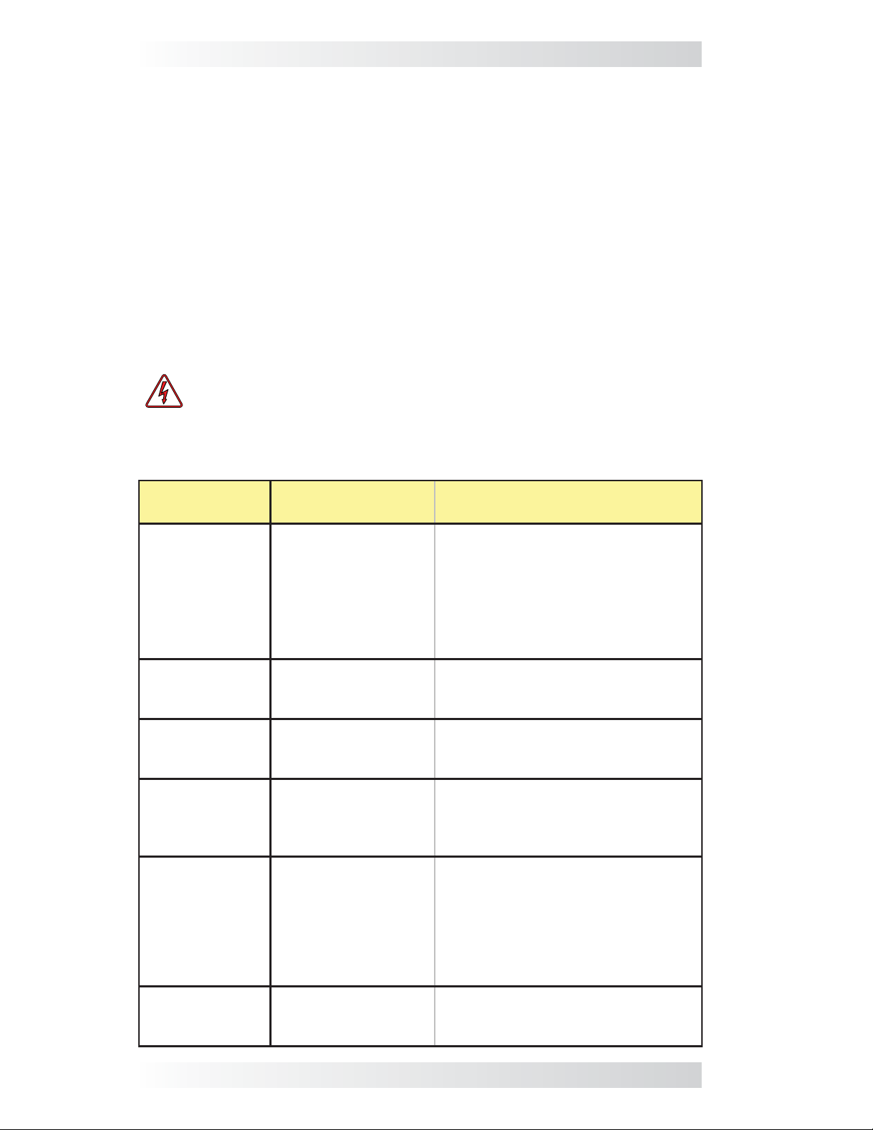
Table 6-1, Troubleshooting Guide
LED
Indication
STATUS is ON
red = Gen Fault
STATUS blinking
green = gen
start initiated
STATUS is ON
(solid) green =
Gen Run
READY is OFF =
no power connected to the
AGS controller
READY is
blinking = the
remote switch is
not connected
Symptom
1. Gen won’t start; or
2. Gen won’t run. It
starts, but is stopped
by the AGS (B+ or
run sense voltage not
sensed to Terminal
#2).
Gen start initiated. No problem – normal operation.
Gen started OK. No problem – normal operation.
DC voltage to pins
3 (+) and 4 (-) on
controller missing or
incorrect.
The remote control
switch is not sensed
or plugged into the
REMOTE port.
Check gen to AGS start wiring; or
check B+ wiring from gen to AGS.
Measure DC voltage from Terminal
2 (+) to Terminal 4 (-), ensure DC
voltage is 10-40 volts only when the
generator is running.
Switch OFF, then ENABLE to reset.
Check fuse, check DC wiring.
1. Check communications cable
connection to the remote and controller, or
2. Try a different 6-conductor telephone cable (see Figure 2-5).
Solutio
n
Switch OFF, then ENABLE to reset.
READY is ON
(solid) = power
connected
25 © 2013 Magnum Energy, Inc.
The remote control
switch is connected
to the REMOTE port.
No problem - normal operation.
Page 29

Warranty and Service
6.0 Limited Warranty
Magnum Energy, Inc. warrants the ME-AGS-S (Automatic Generator Start
- Standalone version) to be free from defects in material and workmanship
that result in product failure during normal usage, according to the following
terms and conditions:
1. The limited warranty for the product extends for twelve (12) months
beginning from the product’s original date of purchase.
2. The limited warranty extends to the original purchaser of the product
and is not assignable or transferable to any subsequent purchaser.
3. During the limited warranty period, Magnum Energy will repair, or
replace at Magnum’s option, any defective parts, or any parts that
will not properly operate for their intended use with factory new or
remanufactured replacement items if such repair or replacement is
needed because of product malfunction or failure during normal usage.
The limited warranty does not cover defects in appearance, cosmetic,
decorative or structural parts, or any non-operative parts. Magnum
Energy’s limit of liability under the limited warranty shall be the actual
cash value of the product at the time the original purchaser returns
the product for repair, determined by the price paid by the original
purchaser. Magnum shall not be liable for any other losses or damages.
4. Upon request from Magnum, the original purchaser must prove the
product’s original date of purchase by a dated bill of sale, itemized
receipt.
5. The original purchaser shall return the product prepaid to Magnum
Energy in Everett, WA. After the completion of service under this limited
warranty, Magnum Energy will return the product prepaid to the original
purchaser via a Magnum-selected non-expedited surface freight within
the contiguous United States and Canada; this excludes Alaska and
Hawaii.
6. If Magnum repairs or replaces a product (with either a new or refurbished
product), its warranty continues for the remaining portion of the original
warranty period or 90 days from the date of the return shipment to
the original purchaser, whichever is greater. All replaced products and
parts removed from repaired products become the property of Magnum
Energy.
7. This limited warranty is voided if:
• the product has been modifi ed without authorization,
• the serial number has been altered or removed,
• the product has been damaged through abuse, neglect, accident,
high voltage or corrosion.
• the product was not installed and operated according to the owner’s
manual.
BEFORE RETURNING ANY UNIT, A RETURN MATERIAL
AUTHORIZATION (RMA) NUMBER IS REQUIRED
© 2013 Magnum Energy, Inc. 26
Page 30

Warranty and Service
6.1 How to Receive Repair Service
If your product requires warranty service or repair, contact either:
• An Authorized Service Center, which are listed on the Magnum Energy
website at
• Magnum Energy, Inc. at:
If returning your product directly to Magnum Energy for repair, you must:
1. Return the unit in the original, or equivalent, shipping container.
2. R eceive a Return Materials Authorization (RMA) number from the factory
prior to the return of the product to Magnum Energy for repair.
3. Place RMA numbers clearly on the shipping container or on the packing
slip.
When sending your product for service, please ensure it is properly packaged. Damage due to inadequate packaging for shipment is not cov-
ered under warranty. We recommend sending the product by tr aceable or
insured service.
http://www.magnumenergy.com/ServiceCenters.htm, or
Telephone: 425-353-8833
Fax: 425-353-8390
Email:
warranty@magnumenergy.com
27 © 2013 Magnum Energy, Inc.
Page 31

Appendix
A-1 Appendix
Optional Accessories for the ME-AGS-S
The following two Pigtail Adapters are available from Magnum Energy for
use with the ME-AGS-S. They are
requirement to conveniently and automatically turn the generator on/off
externally through a manually controlled switch or from an automatically
controlled switching device
turn gen on to run air conditioner):
The ME-PT1 (Pigtail One-wire) adapter is designed to allow the AGS to start
the connected generator when an external +12 volt DC supply is applied.
The ME-PT2 (Pigtail Two-wire) adapter is designed to allow the AGS to start
the connected generator by an external two-contact switch.
(i.e., use air conditioner thermostat controls to
Additional Magnum Equipment/Accessories
The following components are also available from Magnum Energy:
MS Series Inverter/Chargers
The MS Series inverter/charger is a pure sine wave inverter designed
specifi cally for mobile and off-grid applications. The MS Series has a built-in
PFC (Power F actor Corrected) charger that uses 25-30% less AC current than
standard chargers. The MS Series also provides multiple ports, including an
RS485 communication port for network expansion, and a remote port.
MMP Series Enclosures
The MMP175-30D, MMP175-60S, MMP250-30D, and MMP250-60S enclosures
are specifi cally designed for single inverter applications. The MMP Series en-
closures combine all of the major components required for a renewable energy
system—inverter/battery disconnect, AC overcurrent protection, grounding
connections, and a full system inverter bypass—into a single, easy to install
pre-wired enclosure.
Advanced Remote Control Display
The ME-ARC allows advanced features of the Magnum inverter or accessory to
be confi gured. This LCD remote display includes a FA VS button to access your
favorite features quickly and provides advanced monitoring/troubleshooting.
Basic Remote Control Display
The ME-RC remote control is simple to use; an easy-to-read LCD screen
and “at a glance” LEDs display complete inverter/charger status. Soft keys
provide simple access to menus and a rotary encoder knob allows you to
scroll through and select a wide range of settings such as INVERTER ON/OFF,
CHARGER ON/OFF, SHORE power breaker setting, AGS control, and METER,
SETUP, and TECH menus.
Battery Monitor
The Battery Monitor Kit (ME-BMK) is a single battery bank amp-hour meter
that monitors the condition of the battery and provides information to let
you know how much energy you have available. It also lets you plan your
electrical usage to ensure the battery is not being over-discharged.
Fuse Block/Fuses
The Magnum fuse/fuse-blocks are used to protect the battery bank, inverter,
and cables from damage caused by DC short circuits and overloads. They
include a slow-blow fuse with mounting block and protective cover. The 125
and 200-amp models use an ANL type fuse and the 300 and 400-amp models
use a Class-T fuse.
useful in applications where there is a
© 2013 Magnum Energy, Inc. 28
Page 32

PN: 64-0004 Rev B
Magnum Energy, Inc.
2211 West Casino Rd.
Everett, WA 98204
Phone: 425-353-8833
Fax: 425-353-8390
Web:
www.magnumenergy.com
 Loading...