

Page 1
ME-AGS-N
Automatic Generator Start
for Network Versions
Owner’s Manual
Version ≥5.0
For use with the following remote controls:
ME-RC Revisions 1.5 – 2.612
ME-ARC Revisions 2.0 – 2.4
ME-RTR Revisions 2.1 – 2.2
Page 2

Disclaimer of Liability
Since the use of this manual and the conditions or methods of installation,
operation, use and maintenance of the ME-AGS-N (Auto Generator Start Network) is beyond the control of Magnum Energy, Inc., this company does
not assume responsibility and expressly disclaims liability for loss, damage or
expense, whether direct, indirect, consequential or incidental, arising out of
or anyway connected with such installation, operation, use, or maintenance.
Note as well that while every precaution has been taken to ensure the
accuracy of the contents of this manual, the specifi cations and product
functionality may change without notice. Magnum Energy, Inc. assumes no
responsibility for errors or omissions.
Restrictions on Use
The ME-AGS-N may only be used in life-support devices or systems with the
express written approval of Magnum Energy, Inc. Failure of the ME-AGS-N
can reasonably be expected to cause the failure of that life-support device
or system, or to affect the safety or effectiveness of that device or system.
If the ME-AGS-N fails, it is reasonable to assume that the health of the user
or other persons may be endangered.
Copyright Notice
Copyright © 2012 by Magnum Energy, Inc. All rights reserved. Permission to
copy, distribute, and/or modify this document is prohibited without express
written permission by Magnum Energy, Inc.
Document Information
Description – ME-AGS-N Owner’s Manual
Part Number and Revision – 64-0039 Rev A
Date Published – March 2012
This manual is printed without color for cost savings. However, this entire manual is available for download under the Document Library tab at
www.magnumenergy.com with many of the diagrams available in color.
Contact Information
Magnum Energy, Inc.
2211 West Casino Rd.
Everett, WA 98204
Phone: 425-353-8833
Fax: 425-353-8390
Web:
www.magnumenergy.com
Statement of Appreciation
From all of us at Magnum Energy –
Thank you for purchasing this AGS module (ME-AGS-N).
We understand that you have many purchasing options in the marketplace,
and are pleased that you have decided on a Magnum Energy product. This
AGS module was proudly assembled and tested in the United States in our
Everett, Washington, facility.
At Magnum we are committed to providing you with quality products and
services, and hope that your experience with us is pleasant and professional.
Magnum Energy® is a registered trademark of Magnum Energy, Inc.
© 2012 Magnum Energy, Inc. i
Page 3
Important Safety Instructions
This manual contains safety instructions that must be followed during the
installation and operation of this product. Read all instructions and safety
information contained in this manual before installing or using this product.
Safety Symbols
To reduce the risk of electrical shock, fi re, or other safety hazard, the fol-
lowing safety symbols have been placed throughout this manual to indicate
dangerous and important safety instructions.
WARNING: Symbol indicates that failure to take a specifi ed action
could result in physical harm to the user.
CAUTION: Symbol indicates that failure to take a specifi ed action
could result in damage to the equipment.
Info: Symbol indicates information that emphasizes or supplements
important points of the main text.
Remedy: Symbol provides possible solutions for related issues.
Product Safety Alerts
WARNING:
• All electrical work must be performed in accordance with local,
state, and federal electrical codes.
• This product is designed for indoor/compartment installation – do
not expose to rain, snow, moisture, or liquids of any type.
• Use insulated tools to reduce the chance of electrical shock or
accidental short circuits.
WARNING: Severe personal injury, death, and equipment dam-
age can result from operating the generator in a garage, building,
or confi ned space. The generator produces dangerous fumes when
it is running. If the generator is installed in an RV, disable the AGS
system to prevent the generator from starting when the RV is in a
garage, building, or a confi ned space.
WARNING: ENGINE EXHAUST GASSES CAN BE DEADLY. Install a reli-
able carbon monoxide alarm in your vehicle, building, or home before
starting a generator or enabling the AGS. All engine exhaust contains
carbon monoxide: an odorless, colorless gas that can cause severe
personal injury or death. Symptoms of CO poisoning include:
• Dizziness, headache or throbbing temples
• Weakness or muscular twitching
• Sleepiness or confusion
• Nausea or vomiting
If you experience any of these symptoms, get to fresh air immediately.
If symptoms persist, seek medical attention. Shut down the generator
and do not operate until the unit is inspected and repaired.
WARNING: With an Automatic Generator Starting system installed;
exhaust CO, electrical shock, and moving parts hazards are possible due to unexpected engine-generator starting. Disconnect the
engine-generator starting battery cables or the AGS connection to
the engine-generator before working on the generator or any other
electrical system powered by the generator.
ii © 2012 Magnum Energy, Inc.
Page 4

List of Contents
1.0 Introduction .............................................................................1
1.1 ME-AGS-N Module ..................................................................... 1
1.2 ME-AGS-N System Requirements ................................................ 2
1.3 ME-AGS-N Components ............................................................. 2
2.0 Installation ...............................................................................4
2.1 Installation Requirements ..........................................................4
2.2 Required Materials and Tools ......................................................6
2.3 Mounting Procedure ..................................................................6
2.4 Connecting the Cables ............................................................... 7
2.5 ME-AGS-N Terminal Block Wiring Connections ............................. 10
2.6 Common Generator Wiring Diagrams ......................................... 15
2.7 Warning Label ........................................................................ 15
3.0 ME-AGS-N Module Setup .........................................................19
3.1 Confi guring the Internal ME-AGS-N Settings ............................... 19
4.0 ME-AGS-N Module Functional Tests .........................................21
4.1 Power-up Test ........................................................................ 21
4.2 Generator Wiring Test .............................................................. 21
5.0 ME-AGS-N Module Operation ...................................................22
5.1 ME-AGS-N Module TEST Pushbutton .......................................... 22
5.2 ME-AGS-N Module LED Indicators .............................................. 22
6.0 ME-AGS-N Module Troubleshooting ......................................... 23
6.1 Using the ME-AGS-N’s LED Indicators ........................................ 23
6.2 Generator Starting/Running Troubleshooting ............................... 24
7.0 Using a Remote with the ME-AGS-N ........................................26
7.1 AGS to Inverter Compatibility ................................................... 26
7.2 Software Differences Between AGS Revisions .............................. 27
8.0 Using the ME-RC Remote ........................................................28
8.1 ME-AGS-N Setup using the ME-RC ............................................. 28
8.2 ME-AGS-N Functional Tests using the ME-RC ............................... 33
8.3 ME-AGS-N Operation/Monitoring using the ME-RC ....................... 34
8.4 Enabling the ME-AGS-N using the ME-RC ................................... 36
8.5 Starting and Stopping the Generator using the ME-RC ................. 36
8.6 ME-AGS-N Menu Map using the ME-RC ....................................... 37
9.0 Using the ME-ARC Remote ......................................................39
9.1 ME-AGS-N Setup using the ME-ARC ........................................... 39
9.2 ME-AGS-N Functional Tests using the ME-ARC ............................. 52
9.3 ME-AGS-N Operation/Monitoring using the ME-ARC...................... 53
9.4 Enabling the ME-AGS-N using the ME-ARC .................................. 56
9.5 Starting and Stopping the Generator using the ME-ARC ................ 56
9.6 ME-AGS-N Menu Map using the ME-ARC ..................................... 58
© 2012 Magnum Energy, Inc. iii
Page 5

List of Contents (cont.)
10.0 Using the ME-RTR Router ......................................................61
10.1 ME-AGS-N Setup using the ME-RTR ......................................... 61
10.2 ME-AGS-N Functional Tests using the ME-RTR ........................... 73
10.3 ME-AGS-N Operation/Monitoring using the ME-RTR .................... 75
10.4 Enabling the ME-AGS-N using the ME-RTR ................................ 78
10.5 Starting and Stopping the Generator using the ME-RTR .............. 78
10.6 ME-AGS-N Menu Map using the ME-RTR ................................... 80
11.0 ME-AGS-N Remote Status Messages ..................................... 84
11.1 AGS Remote Operational Statuses ........................................... 84
11.2 AGS Remote Start Statuses .................................................... 86
11.3 AGS Remote Fault Statuses .................................................... 87
11.4 General Notes ....................................................................... 88
12.0 ME-AGS-N Remote Troubleshooting ...................................... 89
12.1 AGS Fault Message Screens for Magnum Remotes ..................... 89
12.2 Resolving Operational Statuses ............................................... 90
12.3 ME-AGS-N Faults using your Remote ........................................ 90
13.0 Appendix ..............................................................................94
13.1 Other Accessories and Equipment ............................................ 94
14.0 Limited Warranty ..................................................................95
14.1 How to Receive Repair Service ................................................ 96
List of Tables
Table 3-1, Gen Type Settings ............................................................. 20
Table 6-1, ME-AGS-N Module Troubleshooting Guide ............................. 23
Table 7-1, AGS Compatibility Matrix Chart ........................................... 26
Table 7-2, AGS Revision Differences ................................................... 27
Table 8-1, ME-RC Autostart/Autostop Matrix ........................................ 28
Table 8-2, Software Differences Between ME-RC Revisions .................... 29
Table 8-3, Battery AmpHrs Capacity to Suggested Gen Run Time ........... 30
Table 9-1, ME-ARC Autostart/Autostop Matrix ...................................... 40
Table 9-2, Software Differences Between ME-ARC Revisions ............. 40-41
Table 10-1, ME-RTR Autostart/Autostop Matrix .................................... 62
Table 11-1, AGS Remote Operational Statuses ................................ 84-85
Table 11-2, AGS Remote Start Statuses .............................................. 86
Table 11-3, AGS Remote Fault Statuses .............................................. 87
iv © 2012 Magnum Energy, Inc.
Page 6

List of Figures
Figure 1-1, Components of the ME-AGS-N Module .................................. 3
Figure 1-2, Remote Temp Sensor Cable ................................................ 3
Figure 2-1, ME-AGS-N System Diagram ................................................ 5
Figure 2-2, ME-AGS-N Dimensions ....................................................... 6
Figure 2-3, Remote Temp Sensor Connection ........................................ 7
Figure 2-4, Network Communication Cable ............................................ 7
Figure 2-5, Connecting the AGS to a Magnum Inverter (Small) ................ 8
Figure 2-6, Connecting the AGS to a Magnum Inverter (Large) ................ 8
Figure 2-7, Multiple Network Devices – Star Configuration ...................... 9
Figure 2-8, Multiple Network Devices – Daisy Chain Configuration ............ 9
Figure 2-9, Connected Devices at the Same Potential ........................... 10
Figure 2-10, Generator Run Sense Options.......................................... 12
Figure 2-11, Wiring to the ME-AGS-N Module’s Terminal Block ............... 14
Figure 2-12,
Warning Label ............................................................... 15
Figure 2-13, Two-wire Control Type Generators .................................... 16
Figure 2-14, Three-wire Momentary Control Type Generators ................ 17
Figure 2-15, Three-wire Maintain Control Type Generators .................... 18
Figure 3-1, Inside the ME-AGS-N Module ............................................ 19
Figure 3-2, DC Voltage Settings ......................................................... 19
Figure 5-1, ME-AGS-N Front Panel Controls and Indicators .................... 22
Figure 8-1, ME-RC’s AGS Configuration Access Buttons ......................... 28
Figure 8-2, AGS Menu Maps in ME-RC Remote (Section 1) .................... 37
Figure 8-3, AGS Menu Maps in ME-RC Remote (Section 2) .................... 38
Figure 9-1, ME-ARC’s AGS Configuration Access Buttons ....................... 39
Figure 9-2, AGS Menu Maps in ME-ARC Remote (Section 1) ................... 58
Figure 9-3, AGS Menu Maps in ME-ARC Remote (Section 2) ................... 59
Figure 9-4, AGS Menu Maps in ME-ARC Remote (Section 3) ................... 60
Figure 10-1, ME-RTR’s AGS Configuration Access Buttons ...................... 61
Figure 10-2, AGS Menu Maps in ME-RTR Router (Section 1) .................. 80
Figure 10-3, AGS Menu Maps in ME-RTR Router (Section 2) .................. 81
Figure 10-4, AGS Menu Maps in ME-RTR Router (Section 3) .................. 82
Figure 10-5, AGS Menu Maps in ME-RTR Router (Section 4) .................. 83
Figure 12-1, ME-AGS-N Fault Message – RC and ARC Screens ............... 89
Figure 12-2, ME-AGS-N Fault Message – RTR Screens ........................... 89
© 2012 Magnum Energy, Inc. v
Page 7

1.0 Introduction
1.0 Introduction
Congratulations on purchasing your ME-AGS-N. The ME-AGS-N is the ‘network’ version of Magnum Energy’s Automatic Generator Start (AGS) modules. This AGS is set up and operated via a Magnum Energy inverter and
remote control (i.e., ME-RC, ME-ARC, or ME-RTR). Using the AGS, your generator can automatically start and stop based on the following conditions:
• Battery Voltage: Continuously monitors battery voltage. Autostarts
the generator when the battery voltage falls to a certain level, and
autostops the generator when the battery voltage either rises to a higher level or goes into the Float Charge stage – depending on the remote
control.
• Time of Day: Starts and stops the generator daily based on selectable
start/stop times (determined by the time on the remote control’s clock).
• Inverter Load Amps: Starts/stops the generator based on the loads
powered by the inverter (assists inverter with larger loads).
Note: Only applicable to MS-PAE and MS-PE Series Magnum inverters.
• Rising Temperature: Continuously monitors the temperature of the
surrounding area and automatically starts the generator whenever power is needed to run an air conditioner or to cool down an area.
• Battery SOC: Monitors your battery system and automatically starts
the generator when the battery requires charging – based on the actual
SOC (State of Charge) of the battery.
Note: Battery SOC is a more accurate method than using battery volt-
age as a criteria to determine when a battery requires charging.
Info: The SOC autostart/autostop feature requires the optional ME-BMK
or ME-BMK-NS (Battery Monitor Kit) accessory to accurately determine
the battery’s SOC.
1.1 ME-AGS-N Module
Info: This manual is for the ME-AGS-N with a software revision of
5.0 or higher. Refer to your Magnum remote control manual or the
remote control’s specifi c section in this manual for assistance in
determining the AGS’s software revision#.
Info: If you require an AGS module, but are not using a Magnum inverter/charger, use the ME-AGS-S (AGS – Standalone version).
The AGS is compatible with most AC or DC generators with either 2-wire or
3-wire start controls, such as: Onan, Generac, Martin, Kohler, Honda, Yamaha,
and many others. A list of generators that have been successfully used with
the AGS (and their respective wiring diagrams) can be found at:
http://www.magnumenergy.com/service/genwiringdiagrams.htm
The AGS is equipped with the following operational features:
• Allows manual on and off control (ME-ARC and ME-RTR only) and automatic control of generator
• Compatible with 12, 24, or 48-volt systems
• Easily adjustable settings using the inverter’s remote control menus
(i.e., ME-RC, ME-ARC, or ME-RTR)
• Quiet Time setting to prevent generator operation during nighttime hours
1 © 2012 Magnum Energy, Inc.
Page 8

1.0 Introduction
• TEST button immediately confi rms if installation wiring correct
• Removable 8-port terminal block for easy wiring and powering down
• Front panel LED indicators for gen start/stop status and gen fault
1.2 ME-AGS-N System Requirements
The AGS requires several other components to operate correctly.
Automatic Start Generator – The generator should have automatic starting
capability. The generator must have start and stop controls [i.e., an electric
starter and electric choke (for gasoline units)], and the safety sensors to
be able to start and stop automatically. These safety items include: low oil
pressure, high temperature, engine start over-crank, over/under frequency
(speed), low coolant level, etc. The generator should also supply a “generator
run signal”, which the AGS uses to detect whether the generator is running.
The generator run signal must be from 10 to 40 volts DC, and can be provided
from a generator hour meter signal or a switched B+ terminal.
Info: A generator run signal is not required when using Gen Type:
2-Wire Standby Mode and an AGS with a revision of 5.2 or higher.
Remote Control – A separate remote control (i.e., ME-RC, ME-ARC, or ME-
RTR) is required to confi gure the AGS and to monitor generator starting and
stopping activity. Some of the more advanced generator start/stop features
are not available on the standard ME-RC and require the ME-ARC or ME-RTR
advanced controllers. Refer to your Magnum remote control manual or the
remote control’s specifi c section in this manual to determine your available
AGS autostart and autostop features.
Magnum Inverter – A Magnum inverter is required to communicate net-
work information from the Magnum remote control to the AGS. The inverter
must also have the internal software to work with the remote control and to
allow the desired AGS feature. See Section 7.1 for help in determining your
inverter’s compatibility level.
1.3 ME-AGS-N Components
The ME-AGS-N is shipped with the following:
• AGS module • Network Communications cable
• Remote Temp Sensor cable • ME-AGS-N Owner’s Manual
• Warning label • Mounting screws (x4)
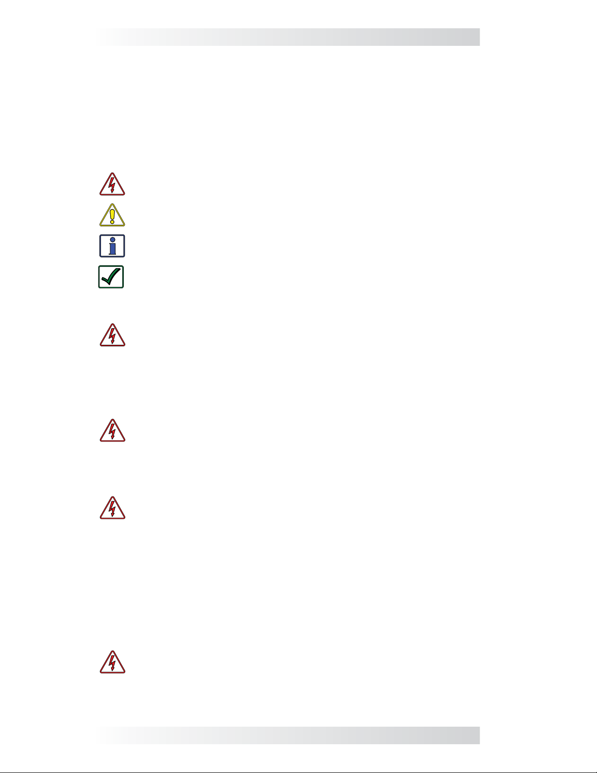
1.3.1 ME-AGS-N Features
The AGS module provides the generator’s wiring connections and the following
components (refer to Figure 1-1):
STATUS Indicator – a bi-color (green or red) LED indicator that
1
illuminates to provide information on the AGS’s operation.
TEST Button – a momentary pushbutton that allows the AGS
system to be tested for correct wiring and generator start/stop
2
operation.
Wiring Terminal Block – an 8-port friction-fi t connector that powers
3
the AGS and connects the generator’s start/stop and run sense wires.
Mounting Flange – used to secure the AGS to a shelf or a wall. Four
black oxide #8 x 3/4 Phillips drive, Pan head screws are provided
4
to mount the AGS.
© 2012 Magnum Energy, Inc. 2
Page 9
1.0 Introduction
READY Indicator – a green LED indicator that illuminates to signal
5
that the AGS is powered (blinks if the optional temp sensor is not
connected).
NETWORK Connection Port (green label) – a RJ14 port (6P4C
- 6 position, 4-contact female connection) which provides the
6
connection point for the network communication cable.
REMOTE Connection Port (purple label) – a RJ14 port (6P4C - 6
position, 4-contact female connection) that provides the connection
7
point for the remote temperature sensor cable (see Figure 1-2).
Internal Access Screws – four #6-32 x 3/8 Phillips screws that
8
must be removed to access the DC Input Jumper and the 4-position
DIP Switch.
4
1
5
2
8
3
6 7
Figure 1-1, Components of the ME-AGS-N Module
Temperature
Sensor
Figure 1-2, Remote Temp Sensor Cable (60 ft.)
3 © 2012 Magnum Energy, Inc.
Page 10
2.0 Installation
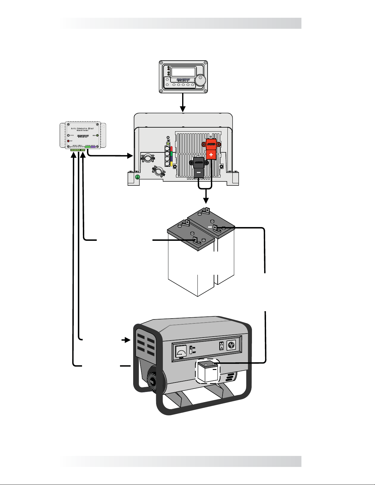
2.0 Installation
Installing the AGS is a simple process. Before installing, read this entire
section so you can thoroughly plan the details to ensure the overall system
requirements are accomplished. To assist you in planning and designing your
installation, review the basic system diagram shown in Figure 2-1.
WARNING: The AGS is not an ignition-protection rated device and
should not be installed in any location that requires ignition-protected
equipment. To prevent fi re or explosion, do not install the AGS module
in any area with extremely fl ammable liquids like gasoline or pro-
pane, or in an area that contains connections between components
of a fuel system.
CAUTION: Installations should be performed by qualifi ed personnel,
such as a licensed or certifi ed electrician. It is the installer’s respon-
sibility to determine which safety codes apply and to ensure that all
applicable installation requirements are followed. Applicable installation codes vary depending on the specifi c location and application.
CAUTION: Review the “Important Safety Instructions” in the front
of this manual before any installation.
2.1 Installation Requirements
Review the following requirements prior to performing the installation:
• For the AGS to automatically start and stop the generator properly, the
generator must include an electric start and an automatic choke. To prevent generator damage and to ensure reliable operation, use generator
models designed for unattended operation. These models should also be
equipped with remote operation connections and have protective systems
that shut down the generator when low oil pressure, over-temperature,
starter lockout, or over-crank conditions occur.
• The AGS is connected to a Magnum inverter by a 10-foot communications
cable. Before installing the AGS and connecting any wires, fi rst determine:
1) the communications cable route throughout the home or vehicle/boat
from the AGS module to the inverter, 2) the start/stop signal wire route
from the AGS module to the generator, and 3) the wire route from the
AGS module to the monitored battery bank.
• Always check for existing electrical, plumbing, or other areas of potential
damage BEFORE drilling or cutting into walls.
• If installing the AGS in a boat, RV or truck, ensure the conductors pass-
ing through walls, bulkheads, or other structural members are protected
to minimize insulation damage such as chafi ng, which can be caused by
vibration or constant rubbing.
• Do not mount the AGS module in a closed battery compartment or in
an area where water (any liquid) can enter the AGS and cause shorting
or corrosion.
• The AGS, if possible, should be wired so as not to interfere with the
manual start/stop switches on your generator, or with your air conditioner
controls if the high temp start feature is used to power the air conditioner.
© 2012 Magnum Energy, Inc. 4
Page 11
2.0 Installation
Magnum remote
PWR
FAULT
Inverting
CHG
INV
ON/OFF
CHARGER
ON/OFF
DC 12.6V 5A
AGS METER SETUPSHOREINVERTER
SELECT
TECH
ME-AGS-N
* Normally the inverter’s
Battery voltage
(12v/24v/48v)
battery bank
Magnum inverter
+
Monitored
Battery
Bank*
Battery bank’s
negative and
generator battery’s
negative must be
connected
Generator
Autostart Generator
start/stop
wiring
Generator
run signal
Gen
Battery
-
+
+
Figure 2-1, ME-AGS-N System Diagram
5 © 2012 Magnum Energy, Inc.
Page 12
2.0 Installation
5
8
3
”
7
8
4
”
3
4
2
1
4
4
”
3
8
”
3
8
5
”
1
4
3
”
3
8
”
2
”
3
16
”
(31.8 mm)
1
4
1
”
(82.6 mm)
(92.8 mm)
(136.6 mm)
(108 mm)
(123.9 mm)
(9.5 mm)
(50.8 mm)
(69.9 mm)
(9.5 mm)
(4.8 mm)
2.2 Required Materials and Tools (not included)
To properly install the AGS module you will need to supply the following:
Required Materials
• 16 to 12 AWG wire for connecting the AGS to the generator start/stop
circuit and to the battery bank
• In-line fuse holders (with a 5-amp DC fuse)
Required Tools
• Phillips screwdriver (#2)
• Flat-blade screwdrivers
(1/4” and 1/8” blades)
• DC voltmeter
• Cut-out tool (knife/saw)
• Drill bits (7/64” & 1/8”)
• Drill
• Wire stripper
• Pencil
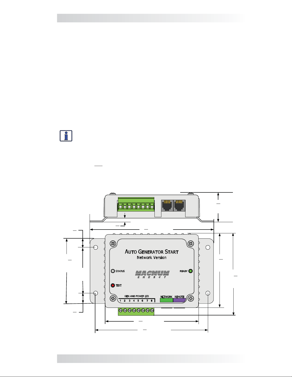
2.3 Mounting Procedure
Select an inside mounting location that is clean, dry, and protected from
extreme temperatures
Info: The AGS module can be mounted in any direction. However,
be sure to allow ample room to
the NETWORK and REMOTE ports
1. Remove the 8-port terminal block from the module (Figure 1-1, Item
3). The terminal block is friction-fi t, remove by pulling it straight out.
Note: Do not plug the terminal block back into the AGS module until
the installation is complete and you are ready to perform the functional
tests (per directions in Section 4.0).
2. Mount the AGS module using the supplied #8 x 3/4” screws (x4).
. Refer to Figure 2-2 for the AGS module’s dimensions.
access the 8-port terminal block, and
.
Figure 2-2, ME-AGS-N Dimensions
© 2012 Magnum Energy, Inc. 6
Page 13
2.0 Installation
12
3
4
12
3
4
TAB
TAB
same color
same
color
ME-AGS-N
Remote
Temp Sensor
cable
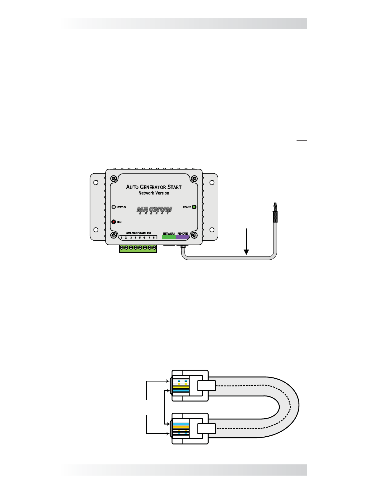
2.4 Connecting the Cables
The AGS comes with two cables: the temp sensor cable is required if using the
temperature autostart feature; the network communication cable is required
for communicating with the inverter/remote.
2.4.1 Connecting the Remote Temp Sensor Cable
If using the temperature autostart feature, connect the plug-in end of the
temp sensor cable to the REMOTE (purple) port of the AGS module, and then
place the other end (with sensor) in the area you wish to monitor (see Figure
2-3). The temp sensor cable is 60 feet long.
If you are not using the temperature autostart feature, the temp sensor
cable does not need to be connected.
Note: The AGS’s READY light will blink if the temp sensor cable is not
connected – this is normal.
Figure 2-3, Remote Temp Sensor Connection
2.4.2 Connecting the Network Communication Cable
The network communication cable is a 10-foot, 4-conductor, fl at, telephony
standard with 6P4C (6-position/4-conductor) connectors on each end. When
the 6P4C connectors are held side by side with both of the connector tabs
facing the same way, the color of the conductors in each connector is the
opposite from top to bottom (as shown in Figure 2-4).
Note: The network communication cable can be extended up to a length of
200 feet without data degradation.
4-conductor
telephone-type
opposite colors
from top to
bottom (tabs
facing toward you)
Figure 2-4, Network Communication Cable
7 © 2012 Magnum Energy, Inc.
Page 14
2.0 Installation
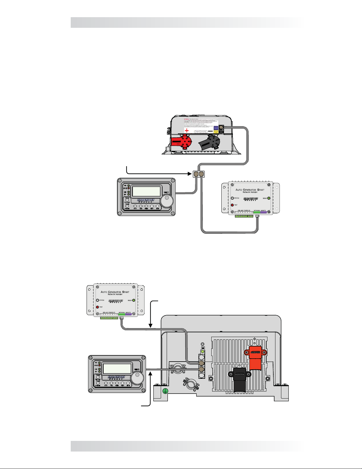
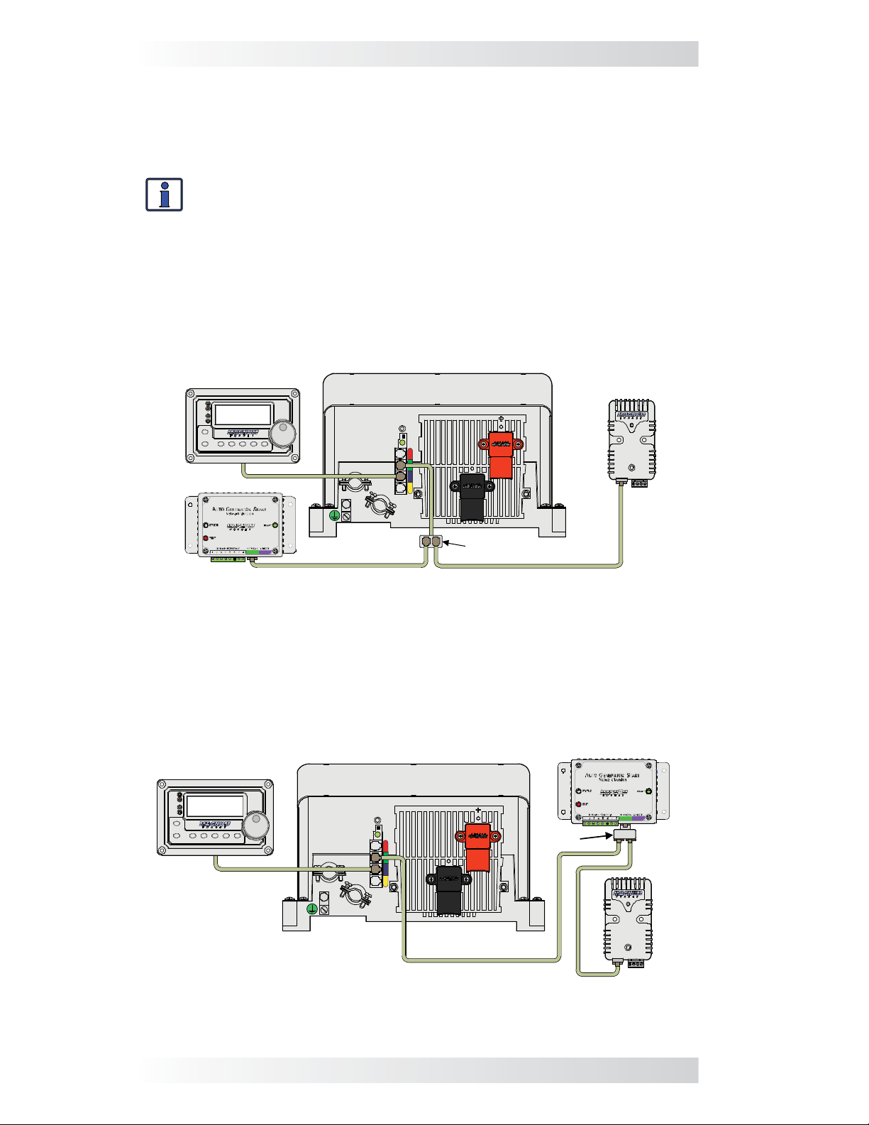
Connecting the AGS to a Magnum inverter: Connect one end of the
communication cable to the AGS’s RJ14 NETWORK (green) port, and then:
• Small inverter (MM/MMS Series) – connect the other end of the
communication cable to a phone splitter, and then connect the splitter
to the REMOTE (blue) port on the small Magnum inverter (see Figure
2-5); or,
• Large inverter (ME, RD, MS, MS-PAE Series) – connect the other
end of the communication cable to the RJ14 Network port (green) on the
large Magnum inverter (see Figure 2-6).
Small Magnum inverter
Phone splitter that connects
AGS network cable (from
AGS’s green NETWORK port)
and remote’s cable to
inverter’s Remote (blue) port
ME-AGS-N
Inverting
DC 12.6V 5A
Remote
Figure 2-5, Connecting the AGS to a Magnum Inverter (Small)
ME-AGS-N
Network Communications
cable from AGS NETWORK
(green) port to inverter’s
Network (green) port
Large Magnum inverter
Remote
Inverting
DC 12.6V 5A
Remote cable to
inverter’s Remote
(blue) port
Figure 2-6, Connecting the AGS to a Magnum Inverter (Large)
© 2012 Magnum Energy, Inc. 8
Page 15
2.0 Installation
2.4.3 Cable Connections with Multiple Devices
If you are using more than one Magnum networked device, a 4-wire phone
splitter is required to connect the devices. There are two options for interconnecting the devices – either in a Star or Daisy Chain confi guration.
Info: Before deciding on which confi guration to use, review the dif-
ferences in installation and ease of troubleshooting.
• Star Confi guration – In this arrangement, all the network devices con-
nect to the inverter’s Network port via a phone splitter, using individual
cable runs (Figure 2-7). Since each device is independently connected
to the inverter’s Magnum Net or Network port, problems in a cable or
a device can be easily isolated; and, if there is a cable failure to one
device it does not bring down all the devices.
Remote Control
PWR
FAULT
Inverting
CHG
DC 12.6V 5A
INV
ON/OFF
CHARGER
ON/OFF
AGS METER SETUPSHOREINVERTER
SELECT
TECH
Magnum Inverter/Charger
ME-BMK
ME-AGS-N
Phone splitter
Figure 2-7, Multiple Network Devices – Star Confi guration
• Daisy Chain Confi guration – In this arrangement, the network de-
vices are linked in a series (Figure 2-8). If using this confi guration, the
ME-AGS-N must be the fi rst device connected to the inverter’s Magnum
Net or Network port – followed by the second network device.
ME-AGS-N (1st device)
Remote Control
PWR
FAULT
Inverting
CHG
DC 12.6V 5A
INV
ON/OFF
CHARGER
ON/OFF
INVERTER
SHORE
AGS
METER SETUP
SELECT
TECH
Magnum Inverter/Charger
Phone
splitter
ME-BMK (2nd device)
Figure 2-8, Multiple Network Devices – Daisy Chain Confi guration
9 © 2012 Magnum Energy, Inc.
Page 16
2.0 Installation
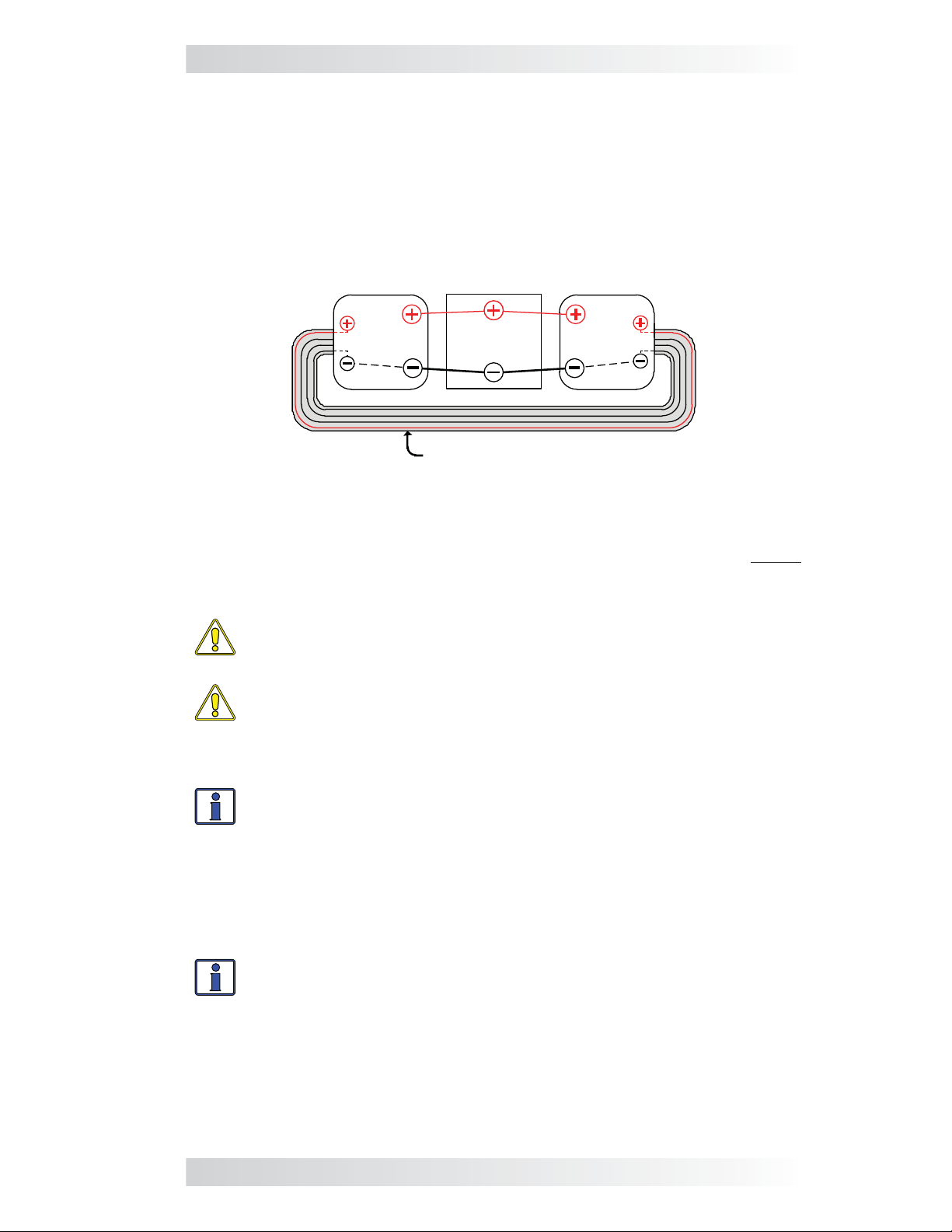
2.4.4 Ensure all Negative Connections are Connected Together
When connecting devices together (via a network communication cable),
the return path (i.e., battery negative) of each battery powered device must
be at the same potential (i.e., electrically common with each other). This
prevents a high-impedance path developing between the connected devices,
which can cause the network cable to become the DC return path to the
battery – possibly resulting in permanent damage to all connected devices
on the network. This also requires that the battery negative connection of
each device be always connected before connecting/disconnecting any battery positive.
Inverter
AGS Inverter
Figure 2-9, Connected Devices at the Same Potential
Inverter
Battery
Battery
Network cable
2.5 ME-AGS-N Terminal Block Wiring Connections
With the AGS already mounted, remove the green 8-port terminal block before
proceeding with wiring the generator. Refer to Figure 2-11 and the info below
to wire the AGS’s terminal block to the generator.
CAUTION: DO NOT plug in the 8-port terminal block until all the
wiring to the module is complete and you are ready to perform the
functional tests (per instructions in Section 4.0).
CAUTION: A fuse rated at 5 amps or less must be used to protect
all power circuits connected to the AGS (do not fuse ground connections). Ensure the fuse is correctly rated for the wire size used. Refer
to national and local codes for rating and type. Normally, a minimum
#16 AWG wire is required in order to use a 5-amp fuse.
Info: The green 8-port terminal block accepts CU/AL conductors from
#30 to #12 AWG (0.05 to 3.3 mm2).
2.5.1 Power Connections (Terminals 3 & 4)
Terminals #3 (positive) and #4 (negative) on the 8-port terminal block are
connected to the monitored battery bank*. These terminals are used to power
the AGS module and to monitor the inverter’s battery voltage (when used to
autostart the generator based on low battery voltage).
Info: The AGS requires a DC input of 8.5-70 volts in order to operate
the internal relays. An input voltage greater than 70 volts will cause
damage to the AGS and is not covered by the product warranty.
* Monitored Battery Bank – When autostarting the generator based on battery
voltage (i.e., start VDC), the inverter’s battery bank must be connected to Terminals #3 (positive) and #4 (negative). If autostarting based on any other condition
(i.e., temperature, amps, etc.), either the inverter battery bank or the generator’s
battery may be used to power the AGS module. However, the negative terminal
of every battery bank must be connected together to prevent damage to the AGS
(see Section 2.4.4).
© 2012 Magnum Energy, Inc. 10
Page 17

2.0 Installation
To make power connections from the monitored battery bank to AGS:
1. Route and connect a wire (black) from the monitored battery bank’s
negative terminal to Terminal #4 on the 8-port terminal block.
2. Route and connect a wire (red) with a 5-amp in-line fuse from the monitored battery bank’s positive terminal to Terminal #3.
2.5.2 Generator Run Sense Connection (Terminals 2 & 4)
A generator run sense signal/voltage is required as it alerts the AGS that the
generator is running; which prevents another starter crank to the generator.
If the gen run sense signal is not provided to the AGS, the AGS commands
the generator to autostop (in case the generator is actually running), and then
attempts another autostart sequence (up to four start attempts before a gen
start fault occurs). The Gen Type switch setting (under Section 3.1) determines
the required gen run sense signal/voltage that must be provided to the AGS.
• Gen Type is 2-Wire Standby Mode* – If your generator is fully auto-
matic and can start, run, and stop using only two wires, you may be able to
use the 2-Wire Standby setting (see Gen Type settings under Section 3.1).
When using this setting, the gen run sense signal is communicated from
the inverter to the AGS thru the network cable. The AGS determines that
the generator is running when the inverter/charger communicates that
it is in a charge state (i.e., Charging, Bulk Charge, Absorb Charge, etc.).
* Requires ME-AGS-N with revision ≥5.2 to use 2-Wire Standby mode.
When using the 2-Wire Standby setting (and the generator is autostarted
by the AGS), the generator runs and connects to the input of the inverter.
This causes the inverter to begin charging, which in turn communicates
to the AGS (via the network cable) that the generator is running – preventing another starter crank command from the AGS.
• Gen Type is not 2-Wire Standby Mode – For all other Gen Type set-
tings (other than 2-Wire Standby mode), the generator run sense must
be 10 to 40 VDC – only while the generator is running. The gen run sense
voltage from the generator is connected to Terminal #2 (positive) and
Terminal #4 (negative) on the green 8-port terminal block on the AGS;
and can be a switched B+ source from the generator, a positive signal
from the generator’s hour meter, or the generator’s running light.
To install the generator’s run sense voltage to the AGS:
1. Connect a wire (preferably not black or red) from the generator’s run
sense output to Terminal #2 on the 8-port terminal block.
2. Connect the negative terminal of the monitored battery bank to Terminal
#4 (power negative) on the 8-port terminal block. Ensure the negative
terminal on the generator battery is referenced/connected to the negative terminal on the monitored battery.
Info: The negative terminal of the monitored battery bank must be in
common with the negative side of the gen run sense signal from the
generator. This ensures that the positive battery voltage (to Terminal
#3) and the positive gen run sense voltage (to Terminal #2) have
a common negative reference (to Terminal #4), and are correctly
sensed/measured by the AGS.
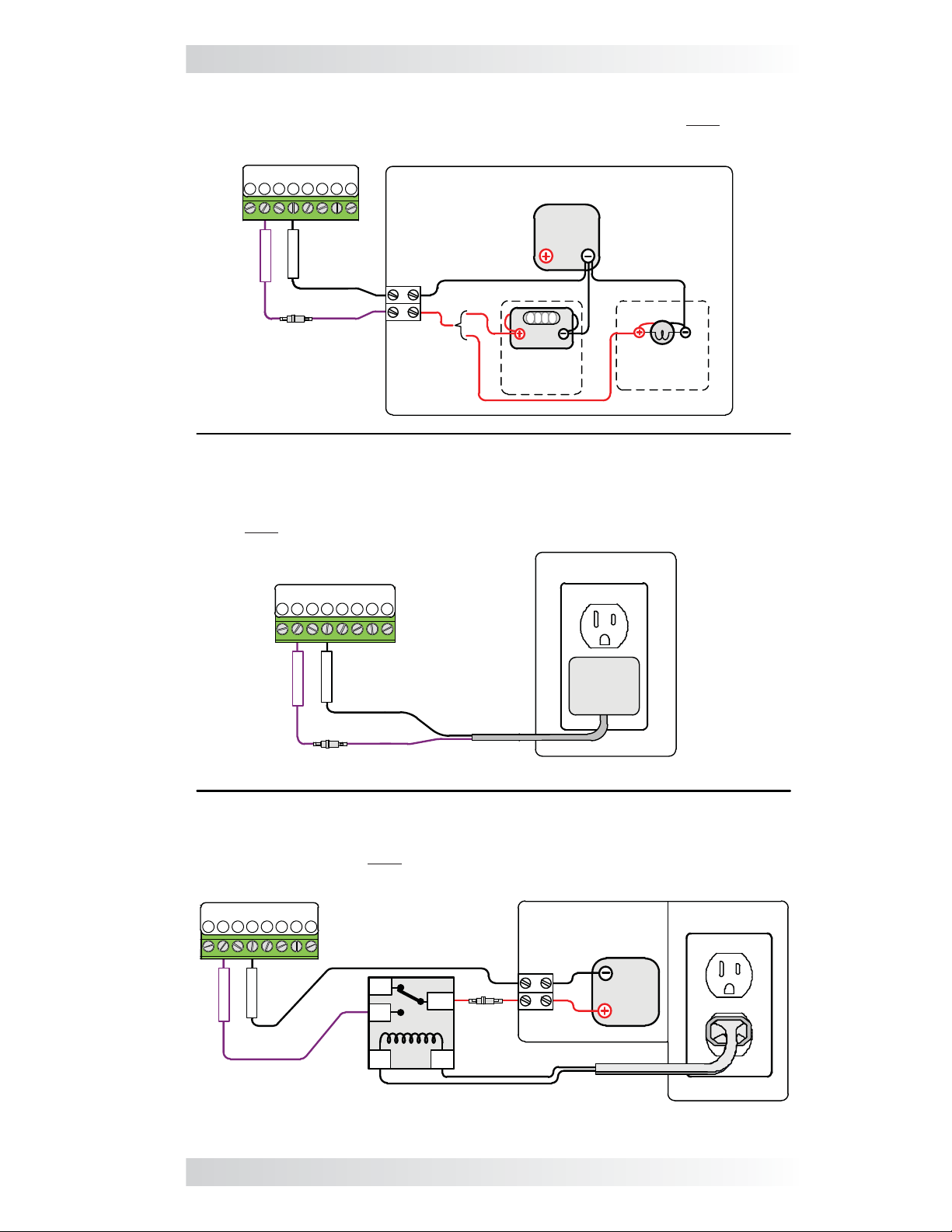
What if my generator does not have a gen run sense output? If your
generator is not equipped with a generator run sense output (10 to 40 VDC only while the generator is running), review the alternative options as shown
in Figure 2-10 to provide this gen run sense voltage to the AGS.
11 © 2012 Magnum Energy, Inc.
Page 18
2.0 Installation
Alternative Option 1 – Tap into the positive side of the generator’s hour
meter or running lamp; ensure the voltage is 10 to 40 VDC only while the
generator is running.
AGS Terminal Block Ports:
1 2 3 4 5
run sense
negative
7 8
6
Inside Generator
Generator
Battery
OR
0123
DC Fuse
(5A max)
Generator
Hour
Meter
Generator
Running
Lamp
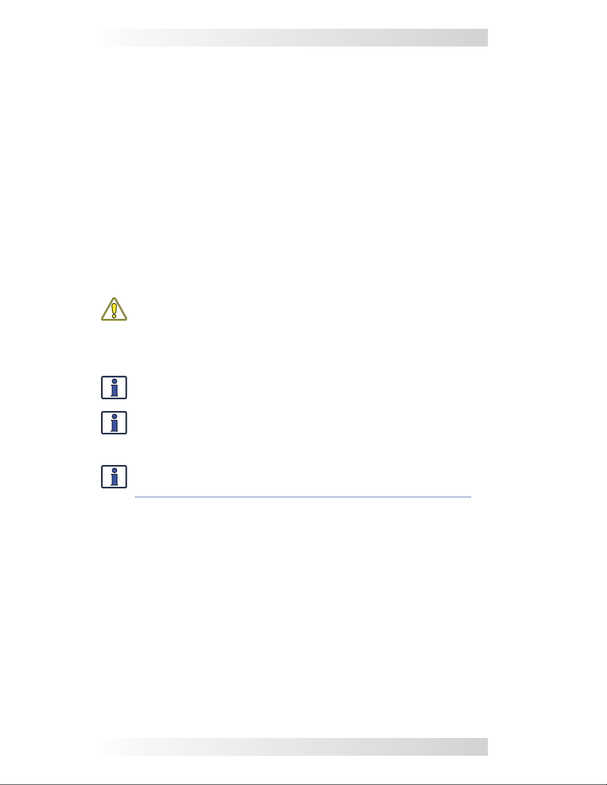
Alternative Option 2 – Use a 120 VAC to 12 VDC step-down transformer
(normally used to charge power equipment batteries) and plug it into the
generator’s 120 VAC output. The step-down transformer provides 12 VDC
output only while the generator is running.
On Generator
AGS Terminal Block Ports:
1 2 3 4 567 8
120VAC Outlet
run sense
negative
120VAC IN
12VDC OUT
TRANSFORMER
DC Fuse
(5A max)
Alternative Option 3 – Use an external 120 VAC coiled relay to bring the
generator’s battery voltage to the AGS gen run sense terminal (AGS terminal
block – Terminal #2) only while the generator is running. The generator’s
battery voltage must be 10 to 40 VDC.
AGS Terminal Block Ports:
1 2 3 4 567 8
run sense
negative
NC
NO
COM
(5A max)
HOT
NEU
120 VAC Coil Relay
Inside Generator
Generator
Battery
DC Fuse
On Generator
120VAC Outlet
Figure 2-10, Generator Run Sense Options
© 2012 Magnum Energy, Inc. 12
Page 19
2.0 Installation
2.5.3 Gen Start/Stop Connections (Terminals 1, 5, 6, 7, & 8)
This section covers the control relays inside the AGS module, and provides
information about wiring these relays to the generator’s start/stop circuit.
You must identify the generator’s start and stop wiring requirements in
order to determine: how many relays you require, the number of wires you
connect, and in what combination.
When the generator is equipped with a remote control terminal or connector,
it is much easier to make the connections to the AGS control relays if
the generator‘s optional remote control is purchased. Connecting to the
generator’s remote also eliminates the need to make connections inside the
generator (and possibly violating the generator’s warranty).
The AGS module provides three control relays (RY1, RY2, and RY3) to
operate the autostart/autostop functions of your generator. These relays are
dry contacts (they do not provide any voltage or current), and operate only
as switches that turn low amperage devices (≤5 amps) on and off. They
are not intended to directly provide power to starter motors or to ignition
systems. Rather, the relays are used to send a signal to operate the coil of
another higher amperage device, which does the actual switching of power.
CAUTION: A fuse rated at 5 amps or less must be used to protect
each of the relays. The warranty does not cover damage to these
relays. Fuses should be located as close as possible to the generator
connection. A fuse must be used, even if the circuit is providing only
a “dry contact” or “ground” connection – it will prevent damage if
the connection is miswired or damaged.
Info: To set the generator type — which determines the operation
of the AGS relays — see the Gen Type setting info in Section 3.1.
Info: Due to the different generator types and the various starting/
stopping wiring confi gurations used by generator manufacturers,
detailed wiring instructions are not provided in this manual. Please
refer to your generator’s documentation for wiring details.
Info: For more information, and to view diagrams on connect-
ing the AGS to the start/stop circuit on many generators, go to
http://www.magnumenergy.com/service/genwiringdiagrams.htm.
Depending on your generator’s start and stop wiring requirements, you may
only need to use one relay (RY1) for fully automatic 2-wire generators; two
relays (RY1 and RY2) for 3-wire generators; or all three relays (RY1, RY2,
RY3) for generators that require an independent bypass or preheat circuit.
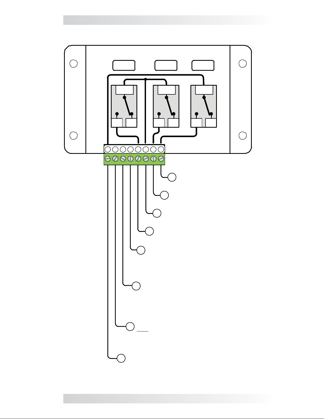
The connection points to each relay are as follows (see Figure 2-11):
• Relay 1 (RY1) and Relay 2 (RY2)
Terminal #5: the Normally Open (N.O.) position of the RY1 relay
Terminal #6: the Common (COM) position of both Relay 1 (RY1) and
Relay 2 (RY2)
Terminal #7: the Normally Open (N.O.) position of Relay 2 (RY2)
• Relay 3 (RY3)
Terminal #1: the Common (COM) position of Relay 3 (RY3)
Terminal #8: the Normally Open (N.O.) position of Relay 3 (RY3)
13 © 2012 Magnum Energy, Inc.
Page 20
2.0 Installation
Relays inside the AGS controller
1
RY1
COM
NO
2 3 4
5 6
RY2 RY3
NONC
COM
NC
COM
NONC
8
7
Normally Open (N.O.)
8
contact on Relay 3 (RY3)
Normally Open (N.O.)
7
contact on Relay 2 (RY2)
Common (COM) contact on
6
Relay 1 (RY1) and Relay 2 (RY2)
Normally Open (N.O.) contact
5
on Relay 1 (RY1)
Negative DC voltage input
4
[negative terminal from monitored battery
bank (positive side connected to Terminal 3),
and the negative side of the run sense signal
(positive side connected to Terminal 2)]
Positive DC voltage input
3
[positive terminal from monitored
battery bank (8.5 to 70 volts DC from
the positive terminal of the monitored
battery bank); negative side is
connected to Terminal #4]
Positive run sense input (10 to 40 volts DC
2
only when generator is running; negative
side is connected to Terminal #4)
Not required if Gen Type setting is 2-Wire
Standby mode
Common (COM) contact on Relay 3 (RY3)
1
Figure 2-11, Wiring to the ME-AGS-N Module’s Terminal Block
© 2012 Magnum Energy, Inc. 14
Page 21
2.0 Installation
2.6 Common Generator Wiring Diagrams
The most common generator starting/run/stop circuits can be divided into
three major types – 2-wire control, 3-wire momentary control, or 3-wire
maintain control. The following gen wiring diagrams are provided as examples:
Info: The term “3-wire” refers to the minimum number of wires
required to control the starter motor and to run the generator; more
than three wires may actually be needed.
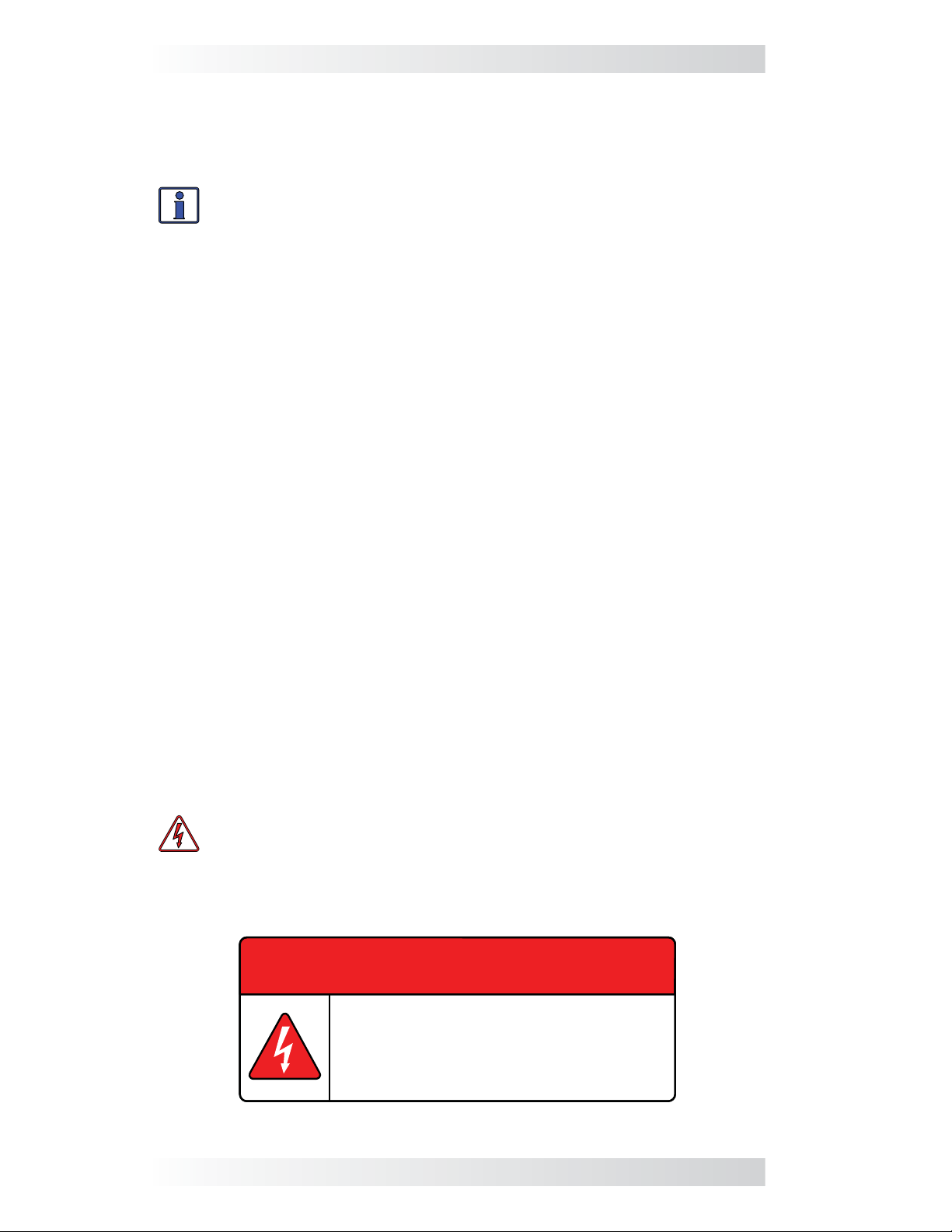
Two-wire control generator types: These generator types integrate the
control circuits for start-up, running, and stopping (Figure 2-13). The generator starts and runs when two control wires are connected, and then stops
when they are disconnected.
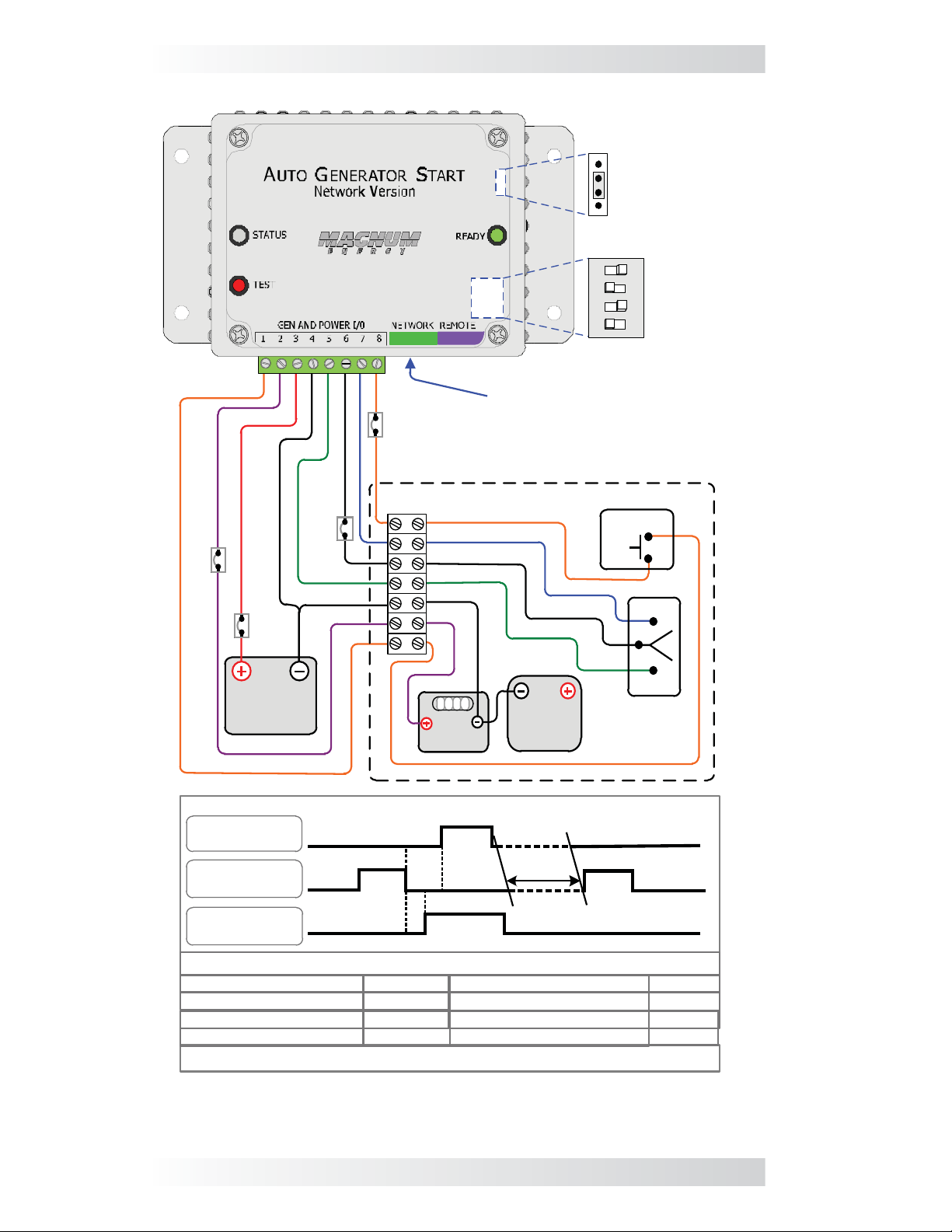
Three-wire momentary control generator types: These generator types
use a three-position momentary type switch that controls their operation
(Figure 2-14). To start the generator, the switch is momentarily held in the
START position. This energizes the ignition system and cranks the starter
motor. Once the engine has started, the switch is released and it returns to a
center position (i.e., “momentary” run control). To shut down the generator,
the switch is held in the STOP position until the engine dies. Once the switch
is released, it returns to the center position (i.e., “momentary” stop control).
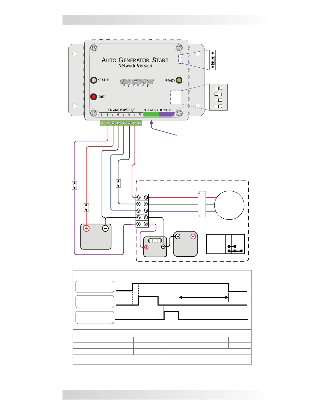
Three-wire maintain control generator types: These generator types use
an automotive type starting circuit (Figure 2-15). To start the generator, an
operating switch is fi rst turned to a RUN position and then momentarily held to
a START position. Once the engine starts, the switch is released and it returns
to the RUN position (i.e., “maintain” run control). To shut down the generator, the switch is moved to the OFF position (i.e., “maintain” stop control).
2.7 Warning Label
It might be falsely assumed that it is safe to perform maintenance on the
generator or the electrical panel once the generator is off. However, the AGS
system can automatically turn on the generator and power the panel.
A warning label (Figure 2-12) is provided to inform all personnel that an
automatic generator starting device is installed in your electrical system.
Place the label in a clearly visible location at the generator (ensure it is
especially visible at the generator cabinet or at the enclosure that guards
electrical shock or moving parts hazards).
WARNING: To prevent harm to servicing personnel, ensure the gen-
erator and AGS are properly disabled (i.e., remove the starting battery
from the generator, and remove all power to the AGS by u
the green 8-port terminal block from the AGS module) prior to per-
forming maintenance on the generator or electrical panel.
nplugging
WARNING
This electrical system is equipped with an Automatic
Generator Starting device and/or an inverter. Disconnect
all AC and DC power to the ME-AGS-N and/or inverter
before performing any service to the electrical system.
Failure to do so can result in shock causing serious injury
or death.
PN: 62-0002 Rev A
Figure 2-12, Warning Label
15 © 2012 Magnum Energy, Inc.
Page 22

2.0 Installation
Input DC Voltage
Jumper - set to
INSIDE
INSIDE
Connected via
communication cable to
inverter’s Network port
monitored battery
bank voltage
12/24/48V
(on 24V setting)
Gen Type
4321
(2-Wire
Maintain
ON
Mode)
≤5
amp
fuse
Inside Generator
Run / Off
Switch
Gen
Battery
RUN
Monitored
battery bank
(12V/24V/48V)
GEN AND POWER I/O
Relay 1
(Terminals 5 & 6)
Relay 2
(Terminals 6 & 7)
Relay 3
(Terminals 1 & 8)
R2 (Relay 2) Time
Delay time
≤5
amp
fuse
≤5
amp
fuse
Ground
GEN RUN PERIOD
OFF
R2
Delay
Timing Information
10 sec.
4 sec.
Time between start attempts
Total start attempts 4
Relay timing for Gen Type: 2-Wire Maintain Mode
0 1 2 3
Gen
Hour Meter
OFF
2 min.
Figure 2-13, Two-wire Control Type Generators
© 2012 Magnum Energy, Inc. 16
Page 23
2.0 Installation
≤5
amp
≤5
amp
fuse
fuse
INSIDE
communication cable to
≤5
amp
fuse
inverter’s Network port
Inside Generator
INSIDE
Connected via
Input DC Voltage
Jumper - set to
monitored battery
bank voltage
12/24/48V
(on 24V setting)
4321
Gen Type
(5-Wire
ON
Mode)
PREHEAT
≤5
amp
fuse
Monitored
battery bank
(12V/24V/48V)
GEN AND POWER I/O
Relay 1
(Terminals 5 & 6)
Relay 2
(Terminals 6 & 7)
Relay 3
(Terminals 1 & 8)
STOP Time
START Time
PREHEAT Time 25 sec.
Start Delay Time 14 sec.
Relay timing for Gen Type: 5-Wire Mode
0 1 2 3
Gen
Hour Meter
START
Start
STOP
Delay
PREHEAT
Delay
Timing Information
10 sec.
10 sec.
Time between start attempts
Gen
Battery
GEN RUN
PERIOD
Preheat delay time
Total start attempts
STOP
STOP
START
4 sec.
2 min.
4
Figure 2-14, Three-wire Momentary Control Type Generators
17 © 2012 Magnum Energy, Inc.
Page 24
2.0 Installation
Input DC Voltage
Jumper - set to
INSIDE
INSIDE
Connected via
communication cable to
inverter’s Network port
monitored battery
bank voltage
12/24/48V
(on 24V setting)
4321
Gen Type
(Portable
ON
Mode)
≤5
amp
fuse
≤5
amp
fuse
Monitored
battery bank
(12V/24V/48V)
GEN AND POWER I/O
Relay 1
(Terminals 5 & 6)
Relay 2
(Terminals 6 & 7)
Relay 3
(Terminals 1 & 8)
≤5
amp
fuse
Inside Generator
0 1 2 3
Gen
Hour Meter
Delay
START
Delay
T1
19
50
30
Gen
Battery
RUN
GEN RUN PERIOD
50
OFF
RUN
START
19
Switch
30
30 50 19
OFF
Timing Information
START Time
T1 Time
10 sec.
5 sec.
Time between start attempts
Total start attempts 4
2 min.
Delay Time 2 sec.
Relay timing for Gen Type: Portable Mode
Figure 2-15, Three-wire Maintain Control Type Generators
© 2012 Magnum Energy, Inc. 18
Page 25
3.0 ME-AGS-N Module Setup
3.0 ME-AGS-N Module Setup
This section covers the AGS’s internal settings and how to configure them.
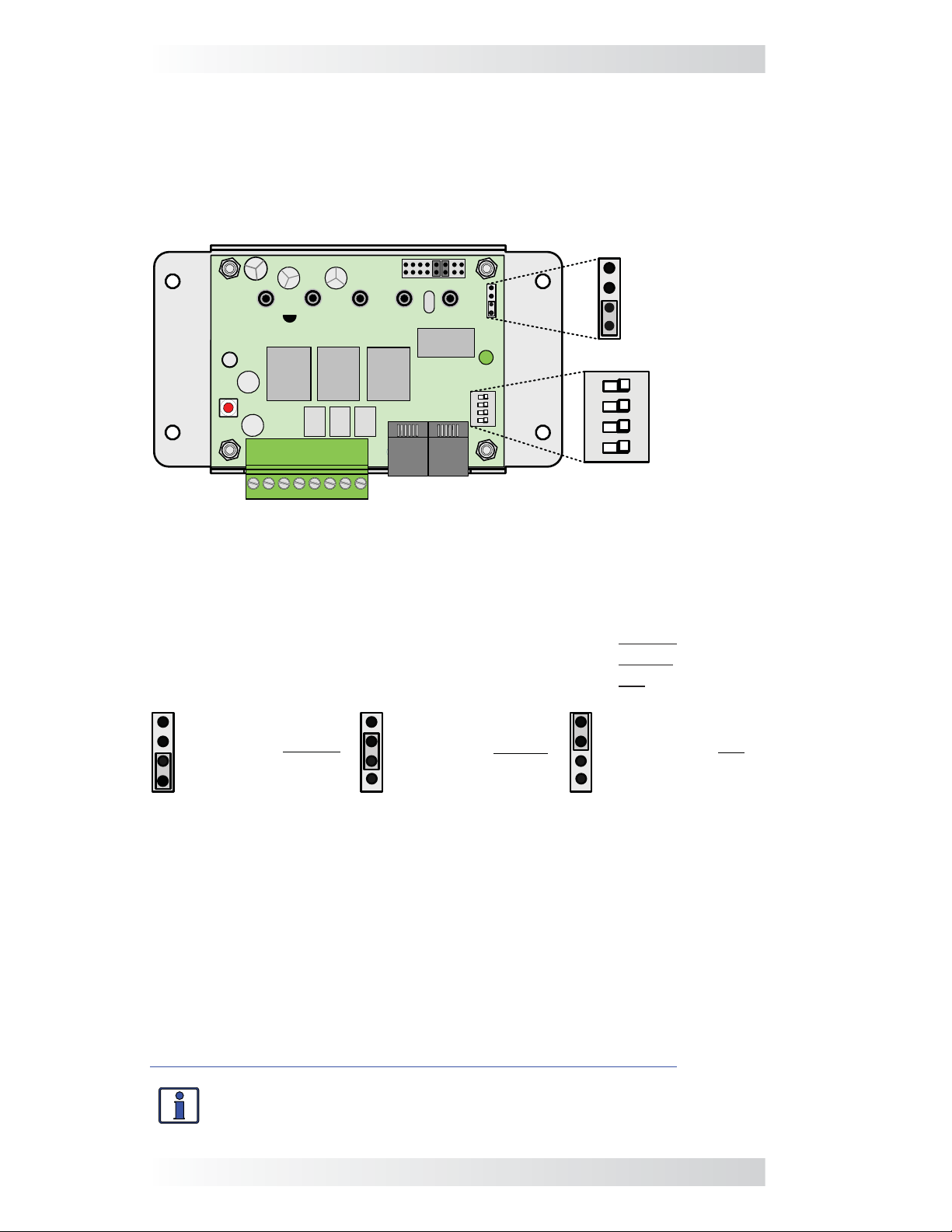
3.1 Confi guring the Internal ME-AGS-N Settings
Unscrew the AGS module’s four top screws and remove the plastic cover to
access the Input DC Voltage Jumper and the 4-position DIP (Dual In-line Package) switch (Figure 3-1).
Input DC
Voltage
Jumper
Setting
(Default: 12V
12/24/48V
Setting)
DIP Switch
4321
Gen Type
Setting
(Default: QD
Mode Setting)
RY1 RY2 RY3
12/24/48V
4321
2
ON
134
ON
Figure 3-1, Inside the ME-AGS-N Module
Input DC Voltage Jumper Setting – This setting is determined by connecting
two small pins with a small, black plastic box (i.e., jumper). This setting can be
confi gured for 12, 24 or 48 VDC operation (Figure 3-2), which is determined
by the nominal DC voltage connected to Terminals #3 and #4 on the AGS.
• For 12-volt DC operation, position the jumper on the bottom two pins.
• For 24-volt DC operation, position the jumper on the middle two pins.
• For 48-volt DC operation, position the jumper on the top two pins.
12 VDC Operation
(jumper on bottom
two pins)
24 VDC Operation
(jumper on middle
two pins)
48 VDC Operation
(jumper on top
two pins)
**default setting**
Figure 3-2, DC Voltage Settings
DIP Switch Gen Type Setting – The Gen Type setting is determined by a
DIP switch, which is actually four small switches that can be turned to the ON
or OFF positions. The position of each of these switches is used to determine
the open and close timing sequence for the three internal AGS relays (RY1,
RY2 and RY3). The multiple positions of the DIP switch allow a wide range of
generator start/stop circuit confi gurations.
After determining the appropriate start/stop timing sequence for your
generator, use Table 3-1 to determine the correct Gen Type setting for your
generator’s start/stop requirements.
For examples and further assistance, view the generator wiring diagrams at:
http://www.magnumenergy.com/service/genwiringdiagrams.htm.
Info: This switch is shipped with a thin yellow plastic fi lm covering.
You can just punch through this thin fi lm to set your gen type.
19 © 2012 Magnum Energy, Inc.
Page 26
3.0 ME-AGS-N Module Setup
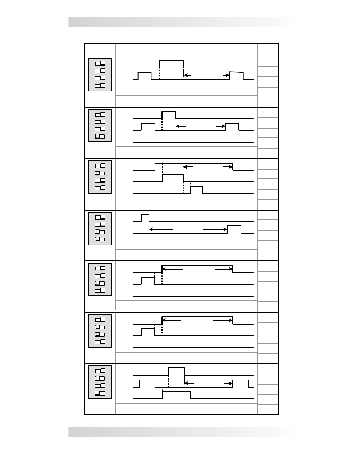
Table 3-1, Gen Type Settings
Gen
Type
4321
ON
QD Mode
(default)
4321
ON
Wire
3-
Mode
4321
ON
Portable
Mode
4321
ON
2-Wire
Momentary
Mode
4321
ON
2-Wire
Maintain
Mode
4321
ON
2-Wire
Standby
Mode*
4321
ON
5-Wire
Mode
Relay Timing/Operation (RY1/RY2/RY3)
RY1
(N.O.)
RY2
(N.O.)
RY3
(N.O.)
Generator: Quiet Diesel Series (Onan). HDZAA model is not
compatible with the AGS-N module – damage may occur.
RY1
(N.O.)
RY2
(N.O.)
RY3
(N.O.)
Generators: Marquis, Emerald, and Microquiet (Onan);
Pack Series (Generac).
RY1
(N.O.)
RY2
(N.O.)
RY3
(N.O.)
Generator: EM Series with remote control (Honda).
RY1
.O.)
(N
RY2
(N.O.)
RY3
(N.O.)
Generator: PT-ECU-63 controller with 2-wires (Powertech).
RY1
(N.O.)
RY2
(N.O.)
RY3
(N.O.)
Generators: RMY Series (Kohler); DynaGen controllers.
RY1
(N.O.)
RY2
(N.O.)
RY3
(N.O.)
Generators: Two-wire start (does not require gen run
voltage signal to Terminal #2).
RY1
(N.O.)
RY2
(N.O.)
RY3
(N.O.)
Generators:
Diesel), NL-673 (Northern Lights).
* ME-AGS-N Revision 5
T2
T3
T3
T1
T2
T2
T1
BTDA / BEG (Westerbeke), 205-DS (Martin
T2
T1
T1
T1
T3
T1
T2
T1
GEN RUN PD.
GEN RUN PD.
GEN RUN PD.
T2
T1
T3
GEN RUN PD.
GEN RUN PD.
GEN RUN PD.
T1
GEN RUN PD.
T4
.2 or higher required
T3
T3
Quiet
T2
T1
Time
Period
T1 =
20 sec.
T2 =
4 sec.
T3 =
10 sec.
T1 =
5 sec.
T2 =
2 sec.
T3 =
10 sec.
T1 =
2 sec.
T2 =
10 sec.
T3 =
5 sec.
T1 =
2 sec.
T2 =
10 sec.
T1 =
4 sec.
T2 =
10 sec.
T1 =
4 sec.
T2 =
10 sec.
T1 =
10 sec.
T2 =
14 sec.
T3 =
4 sec.
T4 =
25 sec.
© 2012 Magnum Energy, Inc. 20
Page 27

4.0 ME-AGS-N Module Functional Tests
4.0 ME-AGS-N Module Functional Tests
After all electrical connections to the AGS module, batteries, and generator
have been completed (and prior to reconnecting the green 8-port terminal
block), perform the following tests to verify that the AGS system is functioning correctly and the wiring from the AGS to the generator is correct. Once
the AGS module passes the functional tests, you can set up the AGS for
your autostart and autostop requirements (refer to: Section 8.0 for a ME-RC
controller, Section 9.0 for a ME-ARC, or Section 10.0 if you have a ME-RTR).
Note: The communication cable from the inverter to the green NETWORK
port on the AGS is not required in order to perform these tests.
4.1 Power-Up Test
1. Before connecting the 8-port terminal block into the AGS module, use a
multimeter to verify the correct polarity and that the voltage to Terminals
#3 (positive) and #4 (negative) is correct according to the position of
the input DC voltage jumper (refer to Figure 3-2).
2. Apply power to the AGS module by plugging in the green 8-port terminal
block into the module, and then verify that the green READY LED comes
on and the STATUS LED blinks green once.
Info: The green READY LED will come on (solid) when the AGS module
is powered and the temperature sensor is connected, and will blink
if the temperature sensor is not connected or detected. A connected
temperature sensor is not required unless the temperature autostart
feature is needed.
4.2 Generator Wiring Test
This start/stop test is used to confi rm that all wiring from the generator to
the AGS module is correct and the Gen Type setting (Table 3-1) is confi gured
correctly for your generator type.
1. Press and release the red TEST button on the AGS (see Figure 5-1).
2. The STATUS LED on the AGS module will begin to blink green and the
generator should start (a blinking green STATUS LED means the AGS has
initiated an automatic generator start/stop sequence).
3. Once the generator starts, it should run for approximately 30-60 seconds
before automatically turning off (ensure the it will not try to restart within
the next two minutes). View the STATUS LED and ensure it turns solid
green (a solid green STATUS LED means the generator has started suc-
cessfully and is providing the gen run sense signal to the AGS module¹).
Note: If the generator attempted to start but did not run, continue to wait,
the AGS will attempt to start the generator 3 more times.
If your AGS/generator system passes all steps above (may attempt an auto-
start 4 times), then the wiring from the AGS to the generator is correct. You
are now ready to set up and activate the AGS using your remote control panel.
Info: The AGS attempts to start the generator 4 times. If after 4
attempts the generator fails to start, the STATUS LED turns red –
indicating a fault.
If the generator did not start, or the STATUS LED shows a fault condition (solid
red LED indication), refer to Section 6.0 “ME-AGS-N Module Troubleshooting”.
Note¹: The gen run sense signal from the generator to Terminal #2 on the
AGS is not required when using the 2-Wire Standby Mode (Gen Type setting).
21 © 2012 Magnum Energy, Inc.
Page 28
5.0 ME-AGS-N Module Operation
5.0 ME-AGS-N Module Operation
This section details the operation of the ME-AGS-N module (independent of
the remote control operation).
5.1 ME-AGS-N Module TEST Pushbutton
The front of the module (Figure 5-1) has a red pushbutton to test the AGS
system operation. When the red TEST pushbutton is pressed and released,
the AGS initiates an automatic generator start/stop sequence. This test
attempts to turn the connected generator on and to have it run for at least
30 seconds before turning off. This start/stop test is used to confi rm that
all wiring from the generator to the AGS is correct and that the AGS is
confi gured correctly for your generator type.
Note: If the generator is running from an autostart condition when the AGS
module’s TEST button is pressed, the AGS will turn the generator off and
initiate an automatic generator start/stop test sequence (running 30-60
seconds) – using 4 autostart attempts if needed.
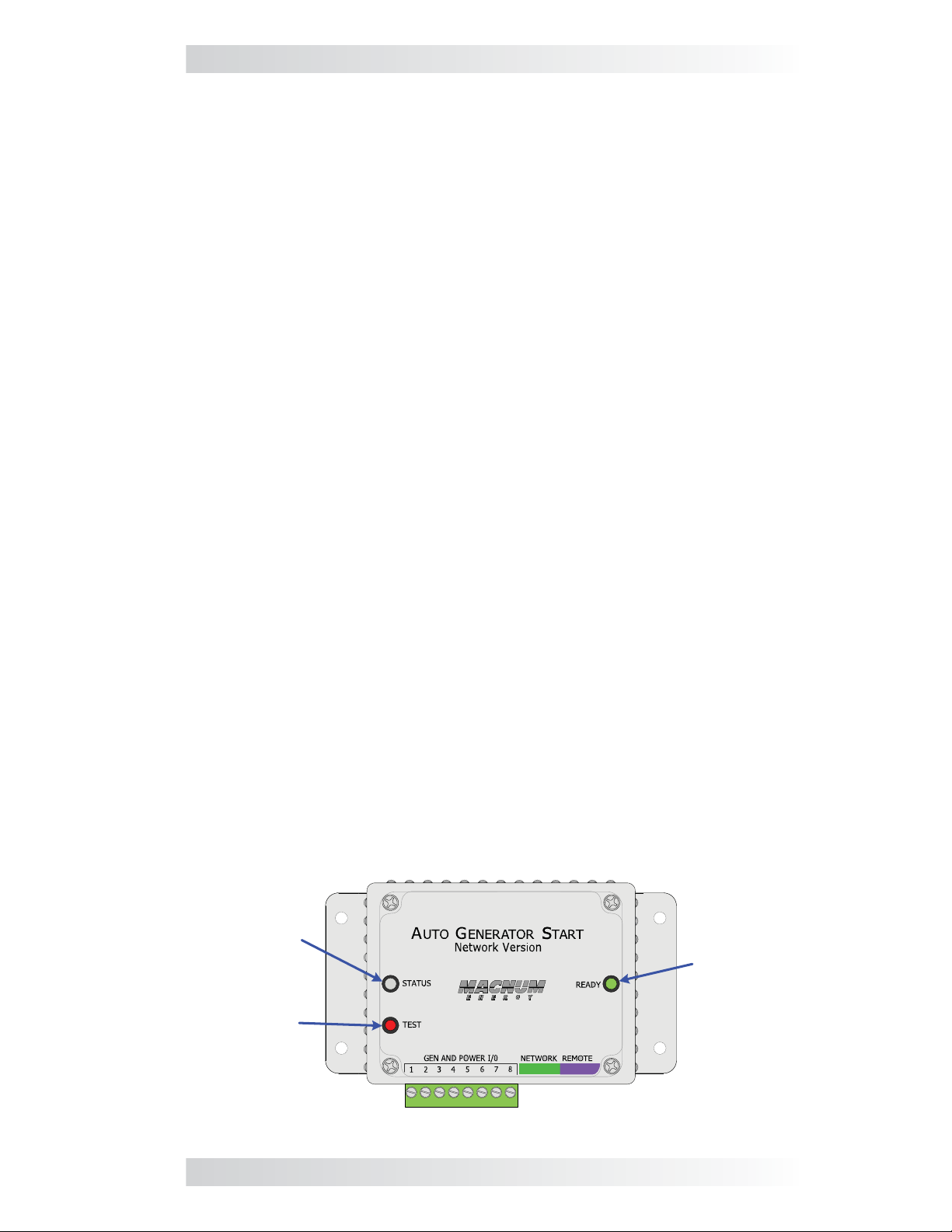
5.2 ME-AGS-N Module LED Indicators
The front of the module (Figure 5-1) has two LED indicators for viewing
system operation.
5.2.1 STATUS LED Indicator
Blinking Green: Indicates that the AGS system is initiating a generator
start sequence. This happens when the TEST button (on the AGS) has been
pressed and released, or a remote control has communicated to the AGS to
autostart the generator.
Solid Green: Indicates the generator has started successfully and is providing
the gen run sense signal/voltage to the AGS module.
Solid Red: Indicates a fault condition in which the generator either has not
started, or has not provided the correct run gen sense signal/voltage to the
AGS module – after four start attempts.
5.2.2 READY LED Indicator
Solid Green: Indicates the AGS module has power and the temperature sen-
sor cable is detected. This indicates normal AGS system operation.
Blinking Green: Indicates that the AGS module has power, but the tempera-
ture sensor is not detected. This can mean the temperature sensor cable is
either not connected, incorrectly connected, or is defective.
Note: The temperature sensor is not required to be connected unless the
temperature autostart feature is needed.
STATUS
Indicator
(green/red)
TEST
Button
READY
Indicator
(green)
Figure 5-1, ME-AGS-N Front Panel Controls and Indicators
© 2012 Magnum Energy, Inc. 22
Page 29
6.0 ME-AGS-N Module Troubleshooting
6.0 ME-AGS-N Module Troubleshooting
6.1 Using the ME-AGS-N’s LED Indicators
The two LEDs on the front of the AGS controller indicate how the AGS is
operating and help you troubleshoot the AGS system. The STATUS LED is bicolor (green or red) and indicates the AGS’s status. The READY LED is green,
and lights if the AGS has power and the remote temp sensor is connected.
The AGS controller performs a “self test” when power is fi rst applied. The
green READY LED lights up (solid) and the STATUS LED blinks green once. If
the self-test is successful, test the AGS system for proper operation by pressing and releasing the TEST button. The STATUS LED blinks green, and the
AGS should start the generator. Once the generator starts, the STATUS LED
lights solid green and the generator runs for approximately 30-60 seconds,
and then shuts off (will not try to restart within the next two minutes). If the
generator does not start and stop as expected, refer to Table 6-1 below to
help fi nd a solution.
WARNING: Completely unplug the green 8-port terminal block from
the AGS module before performing maintenance on the electrical or
generator system to prevent harm to servicing personnel.
Table 6-1, ME-AGS-N Module Troubleshooting Guide
LED
Indication
STATUS is on red
= Gen fault
STATUS is blinking
green = Gen start
initiated
STATUS is on solid
green = Gen run
READY is off =
No power connected to the AGS
module
READY is blinking
= The temperature sensor is not
detected
Note: Temp sensor is not required
to be connected
unless the temp
autostart feature
is needed.
READY is on
(solid) = Power
and temp sensor
connected
Symptom Solution
1. Gen won’t start; or
2. Gen won’t run. It
starts, but is stopped
by the AGS (B+ or gen
run sense voltage not
sensed to Terminal
#2).
Gen start initiated.
Gen is running.
DC voltage to Terminals #3 (+) and #4
(-) on module missing or incorrect.
The temp sensor
is not sensed or
plugged into the
purple REMOTE port.
The temp sensor
is connected to the
purple REMOTE port.
Refer to Section 6.0 “ME-AGS-N Module
Troubleshooting” for assistance.
Unplug/remove and reconnect the green
8-port friction-fi t terminal block to reset
the STATUS (fault) indicator.
No problem – normal operation.
No problem – normal operation.
1. Check fuse, check DC wiring.
2. Check the DC voltage under the AGS
TECH menu.
1. Check the temp sensor cable and its
connection to the purple REMOTE port, or
2. Check the temp sensor cable for any
damage.
3. Obtain another temp sensor cable.
4. Check the DC voltage under the AGS
TECH menu.
No problem – normal operation.
23 © 2012 Magnum Energy, Inc.
Page 30

6.0 ME-AGS-N Module Troubleshooting
6.2 Generator Starting/Running Troubleshooting
This section helps troubleshoot the generator system when the AGS’s STATUS LED shows a fault condition (solid red LED indication), or the remote
control displays a generator autostart fault.
Press the TEST button on the AGS module, or start the generator from the
remote (refer to Section 8.2.1.2 - RC, 9.2.1.2 - ARC, and 10.2.1.3 - RTR).
6.2.1 If the Generator will not Start or Run
If the generator does not start after pressing the AGS module’s TEST button,
follow the steps below.
1. Ensure the green READY indicator on the AGS module is on (blink-
ing or solid) to indicate that the AGS module is getting power
(see Figure 5-1).
2. Check the generator for fuel or for any fault codes, or check the gen-
erator’s operating manual for troubleshooting tips to resolve why the
generator will not start or run.
3. Check that the start/stop wiring has not come loose and is correctly con-
nected for your generator model. A wiring diagram for your particular
brand and model of generator may be available, check our website at:
http://www.magnumenergy.com/service/genwiringdiagrams.htm
4. Your generator may require a higher amperage start signal than what
our AGS relays are rated (approx. 5 amps); in that case, you will need
to supply a higher-rated external relay.
5. If the generator tries to start as soon as you initiate a test (instead of
waiting for the initial stop signal before attempting to start), check the
start and stop wire connections, it is possible that they are reversed.
6. Remove the generator start/stop wires from the AGS’s 8-port terminal.
Simulate the AGS relays by physically connecting the start wires fi rst to
ensure the generator starts and runs. Then, connect the stop wires and
ensure the generator stops. If the generator does not start or stop as it
should, recheck and troubleshoot the start/stop wiring to the generator.
6.2.2 STATUS LED does not go Solid
If the generator is running, but the STATUS LED on the AGS module is not
on solid, then:
1. Ensure the AGS is not in warm-up (STATUS LED should go solid once the
warm-up period is over).
2. Confi rm you are getting the correct gen run sense signal based on your
Gen Type setting.
Info: Refer to the Gen Type Setting section (page 19) and Table 3-1
(page 20) to determine your Gen Type setting.
• Gen Type is 2-Wire Standby Mode – When using 2-Wire Standby
mode, the gen run sense signal is communicated from the remote control to the AGS thru the remote control cable. The AGS determines that
the generator is running when the remote communicates that it is in a
charge state (i.e., Charging, Bulk Charge, Absorb Charge, etc.).
Note: In order to perform the 2-Wire Standby mode tests: the remote
control must be connected to the inverter, and the green Network port
on the inverter must be connected with the communication cable to the
green NETWORK port on the AGS.
© 2012 Magnum Energy, Inc. 24
Page 31

6.0 ME-AGS-N Module Troubleshooting
1. Ensure the remote control is in a charge state (i.e., Charging, Bulk
Charge, Absorb Charge, etc.). If not, then:
a) Ensure the generator’s AC output is connected to the Magnum
inverter’s AC input. Check the wiring and the AC breaker to the
inverter’s AC input.
b) Ensure the AC input breaker on the inverter has not popped out/
opened up.
2. Ensure the network communication cable (Section 2.4.2) and the
remote cable are the correct type (refer to remote’s operating manual).
• Gen Type is not 2-Wire Standby Mode – Except for 2-Wire Standby
mode, all other Gen Types use DC voltage as the gen run sense signal to
the AGS. While the generator is running, use a DC voltmeter to confi rm
there is 10 to 40 volts DC between Terminals #2 (+) and #4 (-) on the
AGS’s green 8-port terminal.
Note: The following tests can be performed without either a remote
control connected to the inverter or the network communication cable
connected from the inverter to the AGS’s green NETWORK port.
A. Use a DC voltmeter to ensure you have a 10 to 40 volts DC reading
between Terminals #2 and #4 while the generator is running. Shut the
generator down, and then recheck voltage to confi rm it has gone away
with the generator being off.
1. If the voltage is correct and goes away when the gen is off, then
the gen run sense signal is correct. Proceed to the remote control
section to set up and enable the AGS to autostart your generator.
2. If the voltage is still present with the generator off, then it is not
a correct gen run sense signal. Determine where it is coming from
and remove or correct it using the gen run sense signal (voltage)
options found in Figure 2-10.
B. If the DC voltage is incorrect or missing between Terminals #2 & #4:
1. Check the fuse and wiring to Terminal #2. The wire on Terminal #2
may be loose, you may have a blown fuse, or the other end of the
wire may not be connected to a proper run signal like the Gen Hour
Meter or one of our alternate gen run sense signal (voltage) options
found in Figure 2-10.
2. Ensure the negative terminal of the monitored battery bank* is in
common/connected with the negative side of the generator battery.
This ensures that the positive battery voltage (to Terminal #3) and
the positive gen run sense voltage from the generator (to Terminal
#2) have a common negative reference (to Terminal #4), and are
correctly sensed/measured by the AGS.
* Monitored Battery Bank – When autostarting the generator based on battery
voltage (i.e., start VDC), the inverter’s battery bank must be connected to
Terminals #3 (positive) and #4 (negative). If autostarting based on any other
condition (i.e., temperature, amps, etc.), either the inverter battery bank or
the generator’s battery may be used to power the AGS module. However, if
different battery banks (inverter and generator) are used, the negative terminal of each battery bank must be connected together to prevent damage
to the AGS (see Section 2.4.4).
25 © 2012 Magnum Energy, Inc.
Page 32

7.0 Using a Remote with the ME-AGS-N
7.0 Using a Remote with the ME-AGS-N
When an AGS is released with a new software revision, some of the features and functionality in the new AGS may not be available in an inverter
or remote control that has an earlier software version. Before continuing to
your specifi c remote control section in this manual, you should evaluate the
software compatibility between your inverter, remote control, and AGS to
determine what AGS features are available.
7.1 AGS to Inverter Compatibility
Magnum Energy’s AGS has many advanced features, and these features
work with your Magnum inverter using the settings/setup menus provided in
a Magnum remote control (i.e., ME-RC, ME-ARC, and ME-RTR). Depending
on the desired AGS feature, you must ensure that the feature is compatible
with your inverter and is available in your remote control.
To determine your inverter’s compatibility level, go to:
http://www.magnumenergy.com/service/compatibility.htm
After identifying the inverter’s compatibility level, use Table 7-1 below to fi nd
the AGS feature and determine if the inverter is at a level that is compatible; and, which remote control and revision is required to provide the AGS
feature you desire.
Turn gen on/off with remote ≥ Level 1 NA ≥ 2.0 ≥ 2.0
Displays DC voltage to AGS ≥ Level 1 ≥ 1.5 ≥ 2.0 ≥ 2.0
Displays gen run time ≥ Level 1 ≥ 1.5 ≥ 2.0 ≥ 2.0
Displays AGS temperature ≥ Level 1 ≥ 1.5 ≥ 2.0 ≥ 2.0
Displays days since gen last ran ≥ Level 1 ≥ 1.5 ≥ 2.0 ≥ 2.0
Gen starts on temp/stops on time ≥ Level 1 ≥ 1.5 ≥ 2.0 ≥ 2.0
Gen starts on VDC/stops on time ≥ Level 1 ≥ 1.5 NA NA
Gen starts on VDC/stops on VDC
or Float charge
Gen starts/stops based on time
of day
Gen starts/stops based on inverter
AC amps
Gen starts/stops based on battery
SOC [Note 2]
Set Max Gen Run Time ≥
Set Gen Quiet Time ≥ Level 1 ≥ 1.5 ≥ 2.0 ≥ 2.0
Set Gen Exercise ≥ Level 1 NA ≥ 2.0 ≥ 2.0
Set Gen Warm-up Time ≥ Level 1 NA ≥ 2.0 ≥ 2.0
Set Gen Cooldown Time ≥ Level 1 NA ≥ 2.0 ≥ 2.0
Table 7-1, AGS Compatibility Matrix Chart
AGS Feature
Inverter
Level
Required ME-RC ME-ARC ME-RTR
≥ Level 1 NA ≥ 2.0 ≥ 2.0
≥ Level 1 NA ≥ 2.0 ≥ 2.0
≥ Level 4
[Note 1]
≥ Level 1 NA ≥ 2.0 ≥ 2.0
Level 1 NA ≥ 2.0 ≥ 2.0
Remote Control /
Revision Required
NA ≥ 2.0 ≥ 2.0
[1] Only applicable to MS-PAE and MS-PE inverters.
[2] The gen start/stop SOC feature requires the ME-BMK (Battery Monitor) to be
installed.
© 2012 Magnum Energy, Inc. 26
Page 33

7.0 Using a Remote with the ME-AGS-N
7.2 Software Differences Between AGS Revisions
This AGS manual covers a ME-AGS-N revision of ≥5.0. There may be differences between revisions that affect your AGS setup/operation, use Table 7-2
below to be aware of the differences between AGS revisions.
Info: Refer to your specifi c remote control section in this manual for
information on determining your AGS revision.
Table 7-2, AGS Revision Differences
ME-AGS-N Revision
Revision Changes 5.0 5.1 5.2
Use 2-Wire Standby
mode (Gen Type setting)
Max Gen Run Time setting can be disabled
Gen Run Time is available for display on
remote
Can I upgrade the software on my ME-AGS-N? Yes, and it’s pretty sim-
ple and not very expensive. For $50 USD plus shipping, you can send your
ME-AGS-N to Magnum Energy and have it upgraded to the latest revision. If
this is something you want to do, contact Magnum Energy to provide us with
your contact and credit card information (VISA or MasterCard only) and we
will provide you with an RMA (Return Material Authorization) number. Once
you have this RMA number, you can send the ME-AGS-N to us and we will
upgrade it to the latest revision available and ship it back to you.
Note: The ME-AGS-N is not the same device as the ME-AGS or ME-AGS-S.
If you have one of these devices, you can contact Magnum Energy to determine if you have any upgrade options.
NA NA YES
NO NO YES
ME-ARC &
ME-RTR only
ME-ARC &
ME-RTR only
ME-RC, ME-ARC
& ME-RTR
27 © 2012 Magnum Energy, Inc.
Page 34

8.0 Using the ME-RC Remote
8.0 Using the ME-RC Remote
The ME-RC remote’s AGS menus under the AGS and TECH buttons allow
you to customize and monitor the operating parameters for your autostart/
autostop generator system. To help confi gure and operate the AGS with your
ME-RC, refer to the mini index below to direct you to the appropriate section.
8.1 ME-AGS-N Setup using the ME-RC page 28
8.2 ME-AGS-N Functional Testing using the ME-RC page 33
8.3 ME-AGS-N Operation/Monitoring using the ME-RC page 34
8.4 Enabling the ME-AGS-N using the ME-RC page 36
8.5 Starting and Stopping the Generator using the ME-RC page 36
8.6 ME-AGS-N Menu Map using ME-RC page 37
Inverting
Status...
DC 12.6V 5A
01 AGS Control
SHORE AGS METER SETUP TECH
AGS and TECH Buttons
Figure 8-1, ME-RC’s AGS Confi guration Access Buttons
This AGS manual covers ME-RC remote controls with a revision of 1.5 to
2.612. There may be differences between revisions that affect your AGS
setup/operation. Use Table 8-2 to familiarize yourself with the differences
between AGS revisions.
Info: Refer to your ME-RC owner’s manual to determine your remote’s
revision (or see the AGS: 08 AGS TECH menu section on page 35).
8.1 ME-AGS-N Setup using the ME-RC
Press the AGS button on ME-RC remote (Figure 8-1), and then rotate the
SELECT knob to navigate to the AGS menus. These menus allow the generator to be automatically started and stopped based on different parameters.
Using Table 8-1, determine the specifi c autostart and autostop condition with
which you want the generator to be automatically controlled, and then use
that specifi c menu setting to confi gure the AGS.
Note: For information on using the AGS: 01 AGS Control, AGS: 02 AGS Sta-
tus, and AGS: 08 AGS TECH menus, refer to Section 8.3 “ME-AGS-N Opera-
tion/Monitoring using the ME-RC”.
Table 8-1, ME-RC Autostart/Autostop Matrix
Autostart
Condition
Gen starts on high
temperature
Gen starts on low
inverter battery
voltage
See AGS
Menu
04 Start
Temp F
05 Start
Volts
Page Autostop
Condition
30 Gen stops
after a set
32
time period
See AGS
Menu
03 Run
Time Hour
Page
30
© 2012 Magnum Energy, Inc. 28
Page 35

8.0 Using the ME-RC Remote
Table 8-2, Software Differences Between ME-RC Revisions
AGS Menu
(Button: Menu)
AGS: 01 AGS
Control
AGS: 02 AGS
Status
AGS: 03 Run
Time Hour
AGS: 04 Start
Temp F
AGS: 05 Start
Volts
AGS: 06 Set
Time
AGS: 07 Quiet
Time
AGS Menu
Selections/Adjustments
Off, Enable, Test, Enable
w/QT
Read Only ≥ Level 1 ≥ Rev 5.0 ≥ Rev 1.5
0.5 - 6.0 Hours ≥ Level 1 ≥ Rev 5.0 ≥ Rev 1.5
0.5 - 25.5 Hours ≥ Level 1 ≥ Rev 5.0 ≥ Rev 2.6
Off, 65 - 90F ≥ Level 1 ≥ Rev 5.0 ≥ Rev 1.5
Off, Ext Input, 65 - 90F ≥ Level 1 ≥ Rev 5.0 ≥ Rev 2.1
Off, Ext Input, 65 - 95F ≥ Level 1 ≥ Rev 5.0 ≥ Rev 2.5
Off, 10.0-12.2, 20.0-24.4,
VDC
Off, 10.0-12.2, 20.0-24.4,
40.0-44.8 VDC
12:00A-12:00P ≥ Level 1 ≥ Rev 5.0 ≥ Rev 1.5
Off, 9PM-7AM, 9PM-8AM,
9PM-9AM, 10PM-8AM,
11PM-8AM
Inverter
Level
≥ Level 1 ≥ Rev 5.0 ≥ Rev 1.5
≥ Level 1 ≥ Rev 5.0 ≥ Rev 1.5
≥ Level 1 ≥ Rev 5.0 ≥ Rev 1.6
≥ Level 1
ME-AGS-N
Required
≥ Rev 5.0 ≥ Rev 1.5
ME-RC
Required
AGS: 08 AGS TECH
Gen Run Read Only ≥ Level 1 ≥ Rev 5.0
AGS VDC Read Only ≥ Level 1 ≥ Rev 5.0 ≥ Rev 1.5
AGS Rev Read Only ≥ Level 1 ≥ Rev 5.0 ≥ Rev 1.5
Temp Read Only ≥ Level 1 ≥ Rev 5.0 ≥ Rev 1.5
AGS Mode RV, Other ≥ Level 1 ≥ Rev 5.0 ≥ Rev 2.5
TECH: 01
Temperatures
TECH: 02
Revisions
Active AGS Fault
AGS: Read Only ≥ Level 1 ≥ Rev 5.0 ≥ Rev 1.5
AGS: Read Only ≥ Level 1 ≥ Rev 5.0 ≥ Rev 1.5
Fault LED = off, Fault
status = view under AGS:
02 AGS Status
Fault LED = blinking, Fault
status = alternates with
inverter/charger status
≥ Level 1 ≥ Rev 5.0 ≥ Rev 1.5
≥ Level 1 ≥ Rev 5.0
≥ Rev 1.5
≥ Rev
2.612
* Requires ME-AGS-N Rev. 5.2 or higher
*
29 © 2012 Magnum Energy, Inc.
Page 36

8.0 Using the ME-RC Remote
AGS: 03 Run Time Hour Menu
This menu provides the settings that determine the length of time the generator will run once it has been autostarted by the AGS.
Default setting: Run Time = 2.0 Hrs
Range: 0.5 Hrs - 25.5 Hrs (0.5 hr increments)
How long should I set the generator run time? This depends on whether
you are using the high temperature or low battery voltage autostart feature.
• Using high temperature to autostart: When using the high tempera-
ture autostart feature, the generator autostarts and runs until the AGS:
04 Start Temp F setting is reached. This means you could set the time
to the lowest time setting (0.5 Hrs), knowing the generator will run until
the temperature setting is satisfi ed.
• Using low battery voltage to autostart: When using the low bat-
tery voltage autostart feature, the generator run time is normally set to
help re-charge the batteries. Use the table below to help determine the
generator run time setting based on the 20-hour AH capacity of your
inverter’s battery bank.
Table 8-3, Battery AmpHrs Capacity to Suggested Gen Run Time
Battery
AmpHrs
Capacity
Suggested
Gen Run Time
200 to 300 1 hour
310 to 500
510 to 700
710 to 900
910 to 1100
1110 to 1300
AGS: 04 Start Temp F Menu
This menu allows you to set and enable a temperature value that will cause
the generator to automatically start — to power an air conditioner (A/C) unit
for cooling — based on an increase in temperature, or by using an air conditioning thermostat control.
Info: The optional ME-PT1 or ME-PT2 pigtail adapters can be used
to connect an air conditioner control circuit or a relay control circuit.
For more information, refer to the instruction sheet for each pigtail
adapter; either part number 64-0025 (ME-PT1 Instruction Sheet),
or 64-0026 (ME-PT2 Instruction Sheet).
This temperature autostart feature requires that the AGS’s remote temperature sensor cable (as shown in Figure 1-2) or an optional ME-PT1 or ME-PT2
pigtail adapter be connected to the REMOTE port on the AGS (see Figure
2-3). The location of the remote temperature sensor determines the area
being monitored for temperature. When the temperature around the remote
temperature sensor (based on the AGS: 08 AGS TECH menu’s Temp display)
increases to the AGS: 04 Start Temp F setting, the generator automatically
starts and runs based on the AGS: 03 Run Time Hour setting. When this run
time period is fi nished, the temperature sensor reading is checked. If the
1.5 hours
2 hours
2.5 hours
3 hours
3.5 hours
Battery
AmpHrs
Capacity
1510 to 1700
1710 to 1900
1910 to 2100
2110 to 2300
2310 to 2500
Suggested
Gen Run Time
4 hours1310 to 1500
4.5 hours
5 hours
5.5 hours
6 hours
6.5 hours
© 2012 Magnum Energy, Inc. 30
Page 37

8.0 Using the ME-RC Remote
temperature sensor (or thermostat control – if using the optional pigtail
adapter) reading is below the AGS: 04 Start Temp F setting, the generator
will autostop. If the temperature sensor (or thermostat control) reading is
above the AGS: 04 Start Temp F setting, the generator will continue to run
for a second run time period. At the end of this second run time period, the
temperature sensor reading (or thermostat control) is checked again. This
cycle continues as long as the AGS: 01 AGS Control menu is set to Enable
(or Enable w/QT).
If the temperature autostart feature is not needed, ensure this setting is set
to the Off position.
• 65F - 95F – These settings determine the rising temperature value that
will trigger a generator autostart.
• Ext Input – This setting is used when an optional AGS adapter (PT1 or
PT2) is used. When an AGS adapter is connected to the AGS’s REMOTE
port, an external command from a thermostat connection on an A/C
control unit causes the generator to start. See the ME-PT1 or ME-PT2
instruction sheets for more information on pigtail adapters.
Default setting: Start Temp = Off
Range: Off, Ext Input, 65F - 95F (5 deg. increments)
Why should I use Start Temp? Typically, in a mobile application (RV or
boat) where the A/C unit is too much power for the inverter to run from the
batteries, this feature is used to start the generator to run an air conditioning
unit. Many RV and marine customers travel with pets and do not want them
to be at risk from dangerous inside temperatures if they are away from the
coach/boat. With this feature, you can set the A/C to turn on and then leave.
Whenever the inside temperature rises to the start setting, the generator
automatically starts to provide power to the A/C unit. This keeps the area
cool and comfortable – plus, while the generator is on, the inverter batteries
are being charged.
Where should I set Start Temp? If you are using this feature to power
an air conditioning unit, the AGS: 04 Start Temp F setting should be slightly
above the A/C unit’s thermostat “cool” temperature (usually around 70-72F).
Once the temperature setting is reached, the generator will start providing
power to the A/C unit. The reason the temperature is set above the A/C
unit’s thermostat is to ensure the A/C unit will run when the generator starts.
If the AGS’s temperature setting is below that of the air conditioning unit’s
thermostat setting, the generator will run, but the A/C unit is not calling for
a run period or cooling; your generator is running, but the power is not being
used by the A/C unit – resulting in wasted fuel and run time.
Info: If using the temperature autostart feature to start a generator
that is powering two A/C units, it is suggested that the second A/C
unit’s thermostat be set 2° to 5° higher than the fi rst A/C unit. This
staggered setting will allow the fi rst A/C unit to start and run in an ef-
fort to keep the coach cool. If the temperature continues to rise inside
the coach, the second A/C unit will turn on to further cool the coach.
31 © 2012 Magnum Energy, Inc.
Page 38

8.0 Using the ME-RC Remote
AGS: 05 Start Volts Menu
This menu allows you to set and enable a battery voltage value that causes
the generator to automatically start. Starting the generator on voltage is the
most common method of autostarting the generator – it is considered the
simplest and easiest to understand. When the battery voltage (on Terminals
#3 & #4) decreases to or below this setting for two continuous minutes, the
generator will automatically start and run based on the AGS: 03 Run Time
Hour setting. If the DC voltage start feature is not needed, ensure this setting is set to the Off position.
Default setting: Start VDC = 11.0 VDC (12v), 22.0 VDC (24v), 44.0
VDC (48v)
Range: Off, 10.0-12.2 VDC (12v), 20.0-24.4 VDC (24v), 40.0-48.8
VDC (48v)
Info: The default settings and range are automatically determined
based on the connected inverter and the measured VDC.
Where should I set Start Volts? When setting the VDC start voltage, it
must be high enough to not over-discharge the battery, but also low enough
to keep from nuisance starting the generator. Typically, start volts is set
based on what is determined to be approximately 50% of the battery capacity. Since this is an inverter/battery system, and the battery is normally
loaded, the VDC used to determine 50% battery capacity should be set lower
than what is shown on typical battery voltage SOC charts (approximately
11-11.5 in a 12-volt system), which show the battery at rest (not loaded).
Info: The DC voltage the AGS uses to determine when to autostart is
displayed in the AGS: 08 AGS TECH menu under the AGS VDC meter.
AGS: 06 Set Time Menu
This menu is used to set the ME-RC remote’s internal clock. The ME-RC
contains a real time clock that must be set for proper operation of the AGS
button’s 07 Quiet Time feature. If the Quiet Time feature is not used, the
time does not need to be set.
Info: The clock obtains power from the inverter and resets if the ME-
RC is disconnected from the inverter, or the inverter is powered down.
To set the current time:
(From the 06 Set Time menu)
• Hour – Rotate the SELECT knob to the correct hour of day, and then
press SELECT.
• Minute – Rotate the SELECT knob to the correct minute setting, and
then press SELECT.
• AM-PM – Rotate the SELECT knob to the appropriate AM or PM setting,
and then press SELECT.
AGS: 07 Quiet Time Menu
This setting is used to prevent the generator from autostarting during a specifi c
designated time period each day.
Info: If the generator is running when the Quiet Time start time
setting is reached, it automatically stops and does not allow the gen
to autostart until after the Quiet Time stop time setting has passed.
To enable, access the Quiet Time menu and select a time period.
© 2012 Magnum Energy, Inc. 32
Page 39

8.0 Using the ME-RC Remote
Default setting: Quiet = Off
Range: Off, 9PM-7AM, 9PM-8AM, 9PM-9AM, 10PM-8AM, 11PM-8AM
Why should I use Quiet Time? Quiet Time is used when there are park
rules or local noise regulations that prevent generators from running during
a certain time. It is usually set in consideration of when people may be sleeping. If there are no local rules or regulations, you may not want to use Quiet
Time – which would allow the generator to run at any time in a 24-hour period.
Where should I set Quiet Time? Select the time period that coincides with
any local noise requirements, or any time period that you do not want the
generator to automatically run.
8.2 ME-AGS-N Functional Tests using the ME-RC
Once you establish all the autostart/autostop settings you need, perform the
following tests to verify that the AGS system is functioning correctly and the
communication from the remote/inverter to the ME-AGS-N is correct.
8.2.1 Remote to Generator Communication Test
This section describes how to determine the current AGS status and how to
use the ME-RC remote to start the generator.
8.2.1.1 Determining AGS Status
Use your remote control to determine the AGS’s status by pressing the AGS
button, rotating the SELECT knob to the 02 AGS Status menu, and then
pressing the SELECT knob.
The AGS’s status should be Off or Ready. If it displays either status, then the
remote/inverter is correctly communicating with the AGS. If the AGS status
displayed is not Off or Ready, then refer to Section 12.2 “Resolving Operational Statuses” or Section 12.3 “ME-AGS-N Faults using your Remote” for
assistance before continuing.
8.2.1.2 Starting the Generator from the Remote
To confi rm that the generator will turn on and run from the remote:
1. Press the AGS button, the bottom line of the remote should display the
01 AGS Control menu.
2. Press the SELECT knob and rotate it to AGS = Test.
3. Press the SELECT knob to activate the generator test.
Once the generator starts, it should run for approximately 30-60 seconds before automatically turning off. View the AGS module’s STATUS LED and ensure
it turns solid green (solid green STATUS LED means the generator has started
successfully and is providing the gen run sense signal to the AGS module).
Note: If the generator attempted to start but did not run, continue to wait,
the AGS will attempt to start the generator 3 more times.
If your AGS/generator system passes all three steps (may attempt an autostart
4 times), then the wiring from the AGS to the generator is correct. You are
now ready to activate the AGS using your remote control panel.
Info: The AGS attempts to start the generator 4 times. If after 4
attempts the generator fails to start, the STATUS LED turns red –
indicating a fault.
If the remote control displays an AGS fault (under 02 AGS Status) or the AGS
module’s STATUS LED shows a fault condition (solid red LED indication), refer
to Section 12.3 for assistance.
33 © 2012 Magnum Energy, Inc.
Page 40

8.0 Using the ME-RC Remote
8.3 ME-AGS-N Operation/Monitoring using the ME-RC
This section covers the AGS menus in the ME-RC remote that determine how
to control and operate the generator. The section also includes menus that are
used to monitor starting and running conditions for the AGS and the generator.
8.3.1 Controlling the AGS using the ME-RC
Press the AGS button, and then rotate and press the SELECT knob to access
the following menus:
AGS: 01 AGS Control Menu
This menu is used to enable the AGS (selecting Enable or Enable
w/QT). A “Test” setting is also available to ensure the start/stop wiring from
the generator to the ME-AGS-N is correct. The available settings are:
• Off – This option disables the AGS’s generator start/stop functions. It
also turns the generator off if it is running from an autostart command.
When Off is selected, the generator will not start automatically. This is
the default setting. If you have an AGS fault, select Off to clear the fault.
Info: If DC power is lost to the remote or to the system, this menu
resets to the default Off position for safety.
• Enable – Select this option to have the AGS monitor temperature (04
Start Temp F) and/or the inverter’s battery voltage (05 Start Volts) to
determine when to automatically start the generator.
• Test – Select this option to test the generator. This option starts the
generator, runs it for approximately 30-60 seconds, and then stops the
generator. Use this setting for testing generator wiring and operation.
After a successful start/stop sequence test, this selection returns to Off.
• Enable w/QT – Select this option to have the AGS monitor tempera-
ture (04 Start Temp F) and/or the inverter’s battery voltage (05 Start
Volts) to determine when to automatically start the generator – with the
Quiet Time parameters enabled.
WARNING: Never allow the generator to start/run in an enclosed
garage or any other type of enclosed structure without proper ventilation. Carbon monoxide, an odorless, colorless, deadly gas may
accumulate and cause serious injury or death.
8.3.2 Monitoring the AGS using the ME-RC
The following menus are helpful for the proper operation and monitoring
of your AGS/generator system. Press the AGS button, and then rotate and
press the SELECT knob to access the following menus:
AGS: 02 AGS Status Menu
This menu allows you to view the AGS’s current status. There are 13 different status messages to identify the AGS’s current state, but only one is
displayed at any one time (refer to the AGS menu map – Figure 8-2).
Available statuses are (refer to Tables 11-1 thru 11-3 for detailed descriptions of each):
• AC In
• Manual Run
• No Comm
© 2012 Magnum Energy, Inc. 34
• Off
• Quiet Time
• Ready
• Start Temp
• Start Test
• Start VDC
• Fault Temp
• Fault Test
• Fault VDC
• Lockout
Page 41

8.0 Using the ME-RC Remote
Info: This menu is important when determining if the AGS is working
correctly, or for troubleshooting an AGS installation.
Info: For any fault mode displayed in the status menu, please refer
to Section 12.0 “ME-AGS-N Remote Troubleshooting” in this manual.
Note: AGS menus 03-07 were covered in Section 8.1. AGS: 08 AGS TECH Menu
This menu displays meter data on the operating condition of the generator
and AGS, and has an AGS mode setting.
• Gen Run – Displays the number of hours the generator has been cur-
rently running from an autostart condition. This menu does not determine run time when the generator has been manually started.
• AGS VDC – Displays the battery voltage currently connected to the AGS
(on Terminals #3 and #4). This voltage is used to power the AGS and is
the voltage reading the 05 Start Volts setting is monitoring to determine
when to start.
• Temp – Displays the current temperature reading of the temperature
sensor and is the temperature the 04 Start Temp F setting is monitoring
to determine when to start. If the temperature sensor is not installed,
the display will either show a very high temperature value (122C/252F),
or “TS open” displays – depending on your remote revision.
• AGS Rev – Displays the software revision of the connected AGS.
Info: The AGS accessory may display a “0.0” revision for several
reasons. Either the AGS is not installed, there is no communication
because of a bad or miswired network cable, the AGS is not powered, or the AGS is bad.
• AGS Mode – This setting allows you to confi gure the AGS to comply
with RVIA standards¹. When the AGS is set to “RV”, the AGS is auto-
matically disabled any time the generator is manually turned on or off.
Select Other if your system is for a RV, or your requirements do not
need the AGS to be disabled should the generator be manually started/
stopped.
Default setting: AGS Mode = RV
Settings: RV, Other
Info: When the RV mode is used and the AGS system feature is
required, the user will need to re-enable the AGS system each time
the generator is manually turned on or off.
Info: If the AGS is automatically disabled when using RV mode, the
AGS status displays “Lockout”.
Note¹ - RV manufacturers use the NFPA 1192 Standard on Recreational
Vehicles for installing an AGS system. This standard has a requirement that
states when the generator is manually turned on or off, the AGS system
must also be turned off. Selecting the “RV” setting satisfi es this requirement
by automatically disabling the AGS system when it senses that the generator
has been manually turned on or off. In installations where the requirement
to automatically disable the AGS system is not needed, the “Other” setting
can be chosen. When the AGS is in the “Other” mode, manually turning the
generator off or on will not automatically disable the AGS system.
35 © 2012 Magnum Energy, Inc.
Page 42

8.0 Using the ME-RC Remote
Press the TECH button, and then rotate and press the SELECT knob to access
the following menus:
TECH: 01 Temperatures
This read-only menu displays the ambient temperature reading of the AGS’s
temperature sensor (if installed). If the temperature sensor is not installed,
the display will either show a very high temperature value (122°C/252°F),
or “TS open” displays – depending on your remote revision.
TECH: 02 Revisions
This read-only menu displays the fi rmware revision level of the AGS module
that is installed and networked.
8.4. Enabling the ME-AGS-N using the ME-RC
Before the AGS can begin operating/monitoring for an autostart condition (using the active AGS settings in your ME-RC remote control), it must be enabled.
To enable the AGS:
1. Press the AGS button. The 01 AGS Control menu displays.
2. Press the SELECT knob. The current gen control setting displays with an
arrow to the right.
3. Turn the SELECT knob to the AGS = Enable setting (or to Enable w/QT).
4. Press the SELECT knob again to select this setting. The selection arrow
appears to the right of the screen.
The AGS is now ready to automatically start/stop the generator once an
autostart condition is satisfi ed.
Note: If power is lost to your remote, the AGS control setting will return to the
default Off setting. Once power is restored, you must enable the AGS again.
Note: Despite enabling the AGS, you must check the AGS’s current status
and ensure the status displays as “Ready”.
8.5 Starting and Stopping the Generator using the
ME-RC
The generator can be manually stopped, as well as autostarted/autostopped
using the available settings from your ME-RC (see Section 8.1).
To autostart/autostop the generator:
In order for the generator to autostart/autostop, one or more of the following autostart/autostop conditions must be pre-set (see Section 9.1):
Autostart Conditions
• 04 Start Temp F (pages 30-31)
• 05 Start Volts (page 32)
• 07 Quiet Time (pages 32-33)
To manually stop the generator (only if autostarted by AGS):
1. Press the AGS button. The 01 AGS Control menu displays.
2. Press the SELECT knob. The current gen control setting displays with an
arrow to the right.
3. Turn the SELECT knob to the AGS = Off setting.
4. Press the SELECT knob again to select this setting. The selection arrow
appears to the right of the screen and the display returns to the 01 AGS
Control menu. The generator should stop at this time.
If the generator does not stop as expected, refer to Section 12.0.
• 03 Run Time Hour (page 30)
• 07 Quiet Time (pages 32-33)
Autostop Conditions
© 2012 Magnum Energy, Inc. 36
Page 43

8.0 Using the ME-RC Remote
8.6 ME-AGS-N Menu Map using the ME-RC
AGS
Status...
01 AGS Control
S
Status...
AGS= Off
Status...
02 AGS Status
S
Status...
AGS: Status
Status...
03 Run Time Hour
S
Status...
Run Time= 0.5Hr
Status...
AGS = Enable
Read Only display
Available Statuses:
AC In Start Temp
Manual Run Start Test
No Comm Start VDC
Off Fault Temp
Quiet Time Fault Test
Ready Fault VDC
Status...
Run Time= 2.0Hr
…
Status...
AGS = Test
Status...
= Enable w/QT
AGS
Lockout
Status...
Run Time=25.5Hr
…
Status...
04 Start Temp F
S
Status... ...
StartTemp = Off
Status...
05 Start Volts
S
Status...
Start VDC= Off
Status...
06 Set Time
S
Status...
Hour = 1:00
S
Status...
Minute = 00:00
S
Status...
AM-PM = 00:00 A
Status...
07 Quiet Time
S
Status...
Quiet= OFF
Status...
Quiet= 11PM-8AM
Status...
Start =Ext Input
Status...
StartTemp = 95F
Start VDC Range: 12-volt = 10.0-12.2 VDC;
24-volt = 20.0-24.4 VDC;
48-volt = 40.0-48.8 VDC
Status...
Start VDC= 10.0
Status...
Start VDC= 12.2
Status...
Hour = 12:00
…
Status...
Minute = 00:59
…
Status...
AM-PM = 00:00 P
Status...
Quiet= 9PM-7AM
Status...
Quiet= 10PM-8AM
Status...
StartTemp = 65F
Status...
Start VDC= 11.0
…
Status...
Quiet= 9PM-8AM
Status...
Quiet= 9PM-9AM
…
…
AGS Menu continues on next page
Figure 8-2, AGS Menu Maps in ME-RC Remote (Section 1)
37 © 2012 Magnum Energy, Inc.
Page 44

8.0 Using the ME-RC Remote
AGS
Status...
08 AGS TECH
S
TECH
Status...
01 Temperatures
S
Status...
02 Revisions
S
Cont.
Status...
Gen Run: x.xHr
Status...
AGS: xxC/xxF
...
Status...
AGS: x.x
…
Read Only displays (except AGS Mode)
Status...
AGS VDC: xx.x
Status...
AGS Mode:RV
S
Status...
AGS Mode=RV
Read Only displays
Read Only displays
LEGEND
Status...
Temp: xxC/xxF
Status...
AGS Rev: x.x
Status...
AGS Mode=Other
AGS
Press button
Press SELECT
Notes: = current setting**
** For this menu map, the arrow denotes the factory default settings
Status...
03 Run Time Hour
S
Status...
Run Time= 0.5 Hr
Menu Button
Inverter/Chrgr Status
Menu Items
Inverter/Chrgr Status
Menu Selections
Setting
Figure 8-3, AGS Menu Maps in ME-RC Remote (Section 2)
© 2012 Magnum Energy, Inc. 38
Page 45

9.0 Using the ME-ARC Remote
9.0 Using the ME-ARC Remote
The ME-ARC remote control’s AGS menus under the CTRL, METER, SETUP,
and TECH buttons allow you to customize and monitor operating parameters,
and to help troubleshoot your autostart/autostop generator system. To help
confi gure and use the AGS with the ME-ARC, refer to the mini index below to
direct you to the appropriate section.
9.1 ME-AGS-N Setup using the ME-ARC page 39
9.2 ME-AGS-N Functional Tests using the ME-ARC page 52
9.3 ME-AGS-N Operation/Monitoring using the ME-ARC page 53
9.4 Enabling the ME-AGS-N using the ME-ARC page 56
9.5 Starting and Stopping the Generator using the ME-ARC page 56
9.6 ME-AGS-N Menu Map using the ME-ARC page 58
Inverting
Status...
DC 12.6V 5A
04 AGS Setup
FAVS CTRL METER SETUP TECH
CTRL, METER, SETUP and TECH Buttons
Figure 9-1, ME-ARC’s AGS Configuration Access Buttons
This AGS manual covers ME-ARC remote controls with a revision of 2.0 to
2.4. There may be differences between revisions that affect your AGS setup/
operation. Use Table 9-2 to familiarize yourself with the differences between
AGS revisions.
Info: Refer to your ME-ARC owner’s manual to determine your re-
mote’s revision (or see the TECH: 02 Revisions – AGS menu section
on page 56).
9.1 ME-AGS-N Setup using the ME-ARC
Press the SETUP button on the ME-ARC remote, and then rotate the SELECT
knob to the 04 AGS Setup display. The menus available from this screen allow the generator to be automatically started and stopped based on many
different conditions. From Table 9-1, determine the specifi c autostart and
autostop conditions with which you want the generator to be automatically
controlled, and then use that specifi c menu setting to confi gure the AGS.
Info: For information on using the CTRL, METER, and TECH button
menus, refer to Section 9.3 “ME-AGS-N Operation/Monitoring using
the ME-ARC”.
39 © 2012 Magnum Energy, Inc.
Page 46

9.0 Using the ME-ARC Remote
Table 9-1, ME-ARC Autostart/Autostop Matrix
Autostart Condition Autostop Condition See SETUP Menu Page
Starts on low battery
voltage (DC voltage connected to Terminals #3
and #4)
Starts at a set time daily Stops at a different set
Starts on high AC amps
to an inverter load¹
Starts when the battery
SOC² is low
Starts when temperature increases
Note¹: Only applicable to MS-PAE and MS-PE inverters.
Note²: Autostart/stop conditions using SOC require the ME-BMK (Battery Monitor).
Stops on higher battery
voltage
Stops at Float charge
after a set time period
(using Absorb Done
Time setting)
Stops at Float charge
after battery current requirement is low (using
Absorb Done Amps)
Stops at Float charge
using a battery SOC setting (using Absorb Done
SOC setting)²
time daily
Stops on lower AC amps
to an inverter load¹
Stops when the battery
SOC² is higher
Stops after a set time
period
04A Gen Run VDC 42
04A Gen Run VDC
(Set Stop Gen Volts
= Float)
04A Gen Run VDC
(Set Stop Gen Volts
= Float)
04A Gen Run VDC
(Set Stop Gen Volts
= Float)
04B Gen Run Time 44
04C Gen Run Amps 44
04D Gen Run SOC 45
04E Gen Run Temp 46
42
42
42
Table 9-2, Software Differences Between ME-ARC Revisions
AGS Menu
(Button: Menu)
CTRL: 03 Gen
Control
METER: 03 AGS Meters
03A AGS Status (Read Only) ≥ Level 1 ≥ Rev 5.0 ≥ Rev 2.0
03B DC Volts - AGS (Read Only) ≥ Level 1 ≥ Rev 5.0 ≥ Rev 2.0
03C Gen Run Time (Read Only) ≥ Level 1 ≥ Rev 5.2 ≥ Rev 2.0
03D AGS Temp (Read Only) ≥ Level 1 ≥ Rev 5.0 ≥ Rev 2.0
03E Since Gen Run (Read Only) ≥ Level 1 ≥ Rev 5.0 ≥ Rev 2.0
SETUP: 04 AGS Setup
04A Gen Run
VDC
Selections/Adjustments
OFF, ON, AUTO, Test ≥ Level 1 ≥ Rev 5.0 Rev 2.0
OFF, ON, AUTO ≥ Level 1 ≥ Rev 5.0 ≥ Rev 2.1
Start = OFF, 9.0-16.0
(12V), 18.0-32.0 (24V),
36.0-64.0 (48V) VDC
Stop = OFF, 9.0-16.0
(12V), 18.0-32.0 (24V),
36.0-64.0 (48V) VDC,
Float
AGS Menu
Inverter
Level
≥ Level 1 ≥ Rev 5.0 ≥ Rev 2.0
ME-AGS-N
Required
ME-ARC
Required
Start/Stop Delay = 0-127
sec., 1-127 min.
© 2012 Magnum Energy, Inc. 40
Page 47

9.0 Using the ME-ARC Remote
Table 9-2, Software Differences Between ME-ARC Revisions (Cont.)
AGS Menu
(Button: Menu)
SETUP: 04 AGS Setup (Cont.)
04B Gen Run
Time
04C Gen Run
Amps*
04D Gen Run
SOC**
04E Gen Run
Temp
04F Max Gen
Run Time
Selections/Adjustments
OFF, ON, Start/Stop =
12AM-12PM
OFF, Start/Stop = 5-60
amps AC
Start/Stop Delay = 0-127
sec., 1-127 min.
OFF, Start = 20-90%
Stop = 21-100%
Start = OFF, Ext Input,
65-95F
Gen Run Temp Time =
0.5-6.0 Hours
Gen Run Temp Time =
0.5-25.5 Hours
0.0-25.5 Hours ≥ Level 1
OFF-25.5 Hours ≥ Level 1 ≥ Rev 5.2 ≥ Rev 2.3
AGS Menu
Inverter
Level
≥ Level 1 ≥ Rev 5.0 ≥ Rev 2.0
≥ Level 4 ≥ Rev 5.0 ≥ Rev 2.0
≥ Level 1 ≥ Rev 5.0 ≥ Rev 2.0
≥ Level 1 ≥ Rev 5.0 ≥ Rev 2.0
≥ Level 1 ≥ Rev 5.0 ≥ Rev 2.4
ME-AGS-N
Required
Rev 5.0 &
5.1
ME-ARC
Required
≥ Rev 2.0
OFF, ON, Start = 12AM-
12PM
04G Quiet
Time
Quiet Time Topoff = OFF,
30, 60, 90, 120 min.
OFF, Days = 1-255
04H Gen
Exercise
Run Time = 0.0-25.5 Hrs
04I Gen
Warm-up
Time
04J Gen
Cooldown
Time
TECH:
01 Temperatures
02 Revisions AGS: Read Only ≥ Level 1 ≥ Rev 5.0 ≥ Rev 2.0
Active AGS Fault
0-127 sec., 1-127 min. ≥ Level 1 ≥ Rev 5.0 ≥ Rev 2.0
0-127 sec., 1-127 min. ≥ Level 1 ≥ Rev 5.0 ≥ Rev 2.0
AGS: Read Only ≥ Level 1 ≥ Rev 5.0 ≥ Rev 2.0
Fault LED = off, Fault sta-
tus = view using METER:
03A AGS Status menu
Fault LED = blinking, Fault
status = alternates with
inverter/charger status
≥ Level 1 ≥ Rev 5.0 ≥ Rev 2.0Stop = 12AM-12PM
≥ Level 1 ≥ Rev 5.0
≥ Level 1 ≥ Rev 5.0 ≥ Rev 2.0
≥ Level 1 ≥ Rev 5.0 ≥ Rev 2.3
≥ Rev 2.0Run Hour = 12AM-12PM
* Only works with MS-PAE or MS-PE inverters.
** The Gen Start/Stop SOC feature requires the ME-BMK (Battery Monitor).
41 © 2012 Magnum Energy, Inc.
Page 48

9.0 Using the ME-ARC Remote
SETUP: 04A Gen Run VDC Menu
This menu starts/stops the generator based on the battery voltage as shown
on the METER button’s 03B DC Volts-AGS menu. This menu provides the option to start the generator when the battery voltage gets low, and to stop the
generator once the battery reaches a higher voltage level, or has been fully
charged and goes into the Float Charge stage. Using voltage to automatically
start and stop the generator is a common method because it is considered
the simplest and easiest to understand. The 04A Gen Run VDC menu also
has a delay setting to minimize nuisance starts/stops and the short cycle run
times of the generator.
• Set Start Gen Volts – This setting will start the generator when the
battery voltage (on Terminals #3 & #4) decreases to or below this setting continuously for the duration of the Set Start Volts Delay setting.
Default setting: Set Start Gen Volts = 11.5 VDC (12v), 23.0 VDC
(24v), 46.0 VDC (48v)
Range: OFF, 9.0-16.0 VDC (12v), 18.0-32.0 VDC (24v), 36.0-64.0 VDC
(48v)
Where should I set Start Volts? When setting the VDC start voltage, it
must be high enough to not over-discharge the battery, but also low enough
to keep from nuisance starting the generator. Typically, start volts is set
based on what is determined to be approximately 50% of the battery capacity. Since this is an inverter/battery system, and the battery is normally
loaded, the VDC used to determine 50% battery capacity should be set lower
than what is shown on typical battery voltage SOC charts (approximately
11-11.5 in a 12-volt system), which show the battery at rest (not loaded).
Info: The DC voltage the AGS uses to determine when to autostart is
displayed in the AGS: 08 AGS TECH menu under the AGS VDC meter.
Example: Using a 12-volt battery as an example, a typical SOC (State of
Charge) battery chart will show that 12.2 VDC is considered 50% SOC. This
voltage is a battery “at rest,” meaning it has no load connected and has been
at rest for a minimum of 30 min. While this voltage is accurate under these
at rest conditions, this same voltage with a load applied means the battery is
well above 50% SOC, and should be set much lower. The larger the battery
bank the less the voltage will be affected by a load applied to the battery
bank. A typical start voltage setting would be between 11.0 VDC - 11.5 VDC
for a 12-volt system.
• Set Start Volts Delay – This setting determines how long the Start
Gen Volts parameter must be continuously maintained before the gen-
erator autostarts. This ensures the generator does not nuisance start.
By setting a delay, momentary surge loads will not start the generator
when the battery voltage dips due to the heavy load applied to the
battery.
Default setting: Set Start Volts Delay = 120 Seconds
Range: 0 - 127 Seconds, 1 - 127 Minutes
Where should I set Start Volts Delay? Determine what loads will be
running when the generator needs to start. The larger the load the shorter
the delay time setting. When a large load is applied to the battery bank the
battery voltage drops quickly, so the delay time should be short to ensure
the batteries are not over-discharged. If you are unsure what loads might
be running or where to set the start delay, error on setting a shorter time
such as the default of 2 minutes (to protect batteries from over-discharge).
© 2012 Magnum Energy, Inc. 42
Page 49

9.0 Using the ME-ARC Remote
• Set Stop Gen Volts – This setting will stop the generator when the
battery voltage (on Terminals #3 & #4) increases to or above this setting continuously for the duration of the Set Stop Volts Delay setting. To
allow the battery bank to go through a full bulk and absorption charge,
this setting should be set to Float.
Default setting: Set Stop Gen Volts = 14.4 VDC (12v), 28.8 VDC
(24v), 57.6 VDC (48v)
Range: OFF, 9.1-16.0 VDC (12v), 18.2-32.0 VDC (24v), 36.4-64.0 VDC
(48v), Float
Where should I set Stop Gen Volts? Typically, when using a generator
to charge batteries, most individuals only charge the batteries to 80-85%
to compromise between minimizing fuel usage and maximizing battery life.
This is done by having the generator start on low battery voltage, and then
stop at a higher voltage (i.e., the Stop Gen Volts setting). When deciding
where to set the Stop Gen Volts setting, it must be lower than the inverter’s
Absorb Voltage setting (determined by the SETUP: 03B Battery Type menu).
Otherwise, the charger will enter Absorption Charge mode — which is required to maintain the batteries at a constant voltage level — and the battery voltage will not reach the Stop Gen Volts setting, which will cause the
generator to run until it is out of fuel or until it reaches the SETUP: 04F Max
Gen Run Time setting.
Therefore, after reading this some will think that they should just set the
Stop Gen Volts setting slightly lower than the absorption level to ensure
the charger always reaches the Stop Gen Volts setting before it goes into
the Absorption Charge mode. However, temperature changes can affect the
absorb voltage setting¹ and may require you to readjust the Stop Gen Volts
setting seasonally. If you are in a normally cold climate (<32°F), the actual
absorb charge voltage will increase. So, the Stop Gen Volts setting should be
set well above the absorb voltage setting (~.5V above for 12-volt systems).
If you are normally in a hot climate (>95°F), the actual absorb charge voltage will decrease. In that case, the Stop Gen Volts setting should be set well
below the absorb voltage setting (~.5V below for 12-volt systems).
A simpler way to charge the batteries to 80-85% and to automatically allow
a temperature-compensated charge to the batteries (no seasonal adjustment required) is accomplished using the settings below:
• Set the Stop Gen Volts setting to Float
• Set the Absorb Voltage setting (SETUP: 03B Battery Type) to the volt-
age level at which you want the generator to turn off (normally ~ 14.5
volts for fl ooded batteries in a 12-volt system)
• Set the Absorb Done Time setting (SETUP: 03E Absorb Done Time) to
0.1 hours (lowest setting)
Using these settings, when the batteries reach a low voltage level the generator turns on (per the Set Start Gen Volts setting) and charges the battery
to the temperature-compensated Absorb Voltage setting. After reaching the
absorption voltage level, the inverter/charger goes into Absorption Charge
mode and is there for only 6 minutes (0.1 hours) before it goes to Float
Charge mode. Once the inverter/charger enters Float Charge mode, the AGS
will autostop the generator.
Note¹: When the inverter’s Battery Temperature Sensor (BTS) is connected,
the actual absorb charge voltage will increase or decrease to ensure correct
charging as the battery temperature changes.
43 © 2012 Magnum Energy, Inc.
Page 50

9.0 Using the ME-ARC Remote
Info: Battery life will be reduced if the batteries are only charged to
80-85% regularly. It is highly recommended to charge the batteries
to 100% as often as possible (~ once a week, or every other discharge cycle) in order to avoid sulfation of the battery plates. Using
the SETUP: 03E Absorb Done Time menu, the absorption charge time
can easily be changed to a longer duration to increase the batteries’
state of charge.
• Set Stop Volts Delay – This setting determines the amount of time the
generator will run after the Stop Gen Volts setting has been satisfi ed.
Default setting: Set Stop Volts Delay = 120 Seconds
Range: 0 - 127 Seconds, 1 - 127 Minutes
SETUP: 04B Gen Run Time Menu
This menu starts and stops the generator based on a specifi c time of day.
This feature uses the ME-ARC’s internal clock to start and stop the generator
at the selected times.
Info: Ensure the remote’s clock is correct. If needed, refer to the
ME-ARC owner’s manual for guidance on setting the time on the
remote clock.
Info: The ME-ARC clock is powered from the inverter thru the remote
cable. If the ME-ARC or inverter loses power, the clock will lose the
correct time and must be reset.
• Set Gen Run Time – This setting allows set times to be established to
turn the generator on and off each day. Select ON to set specifi c times
of day to start and stop the generator.
Default setting: Set Gen Run Time = OFF
• Set Start Gen Hour – Set the hour the gen will start each day.
• Set Start Gen Minute – Set the minute the gen will start each day.
• Set Start Gen AM-PM – Set the time period the gen will start.
• Set Stop Gen Hour – Set the hour the gen will stop each day.
• Set Stop Gen Minute – Set the minute the gen will stop each day.
• Set Stop Gen AM-PM – Set the time period the gen will stop.
Why should I set a specifi c time of day to start/stop the generator?
Starting and stopping at a particular time of day can be useful if you want
to run the generator for other uses while charging the batteries. You may
require the generator to run a heavy load (like a well pump or machinery)
every day at the same time. You may also want the generator to run after
you leave for work each day to avoid having to hear it running.
SETUP: 04C Gen Run Amps Menu
This menu starts the generator based on the amount of AC amps needed to
handle the load the inverter is running. The METER button’s 02C Load Amps
menu is used to determine how much load the inverter is currently running
when in Inverter mode.
Info: The 04C Gen Run Amps menu is only applicable to Magnum’s
MS-PAE and ME-PE Series inverters.
Why use Gen Run Amps? This setting is useful when there is a large load
or a combination of loads that the inverter can run, but doing so quickly depletes the battery bank (motors, well pumps, A/C units, freezer, etc.).
© 2012 Magnum Energy, Inc. 44
Page 51

9.0 Using the ME-ARC Remote
• Set Start Gen AC Amps – This setting determines when the generator
would start depending on the AC amps level of the load the inverter is
running. In order for the generator to autostart, the load’s amps level
must be maintained continuously above the Start Gen AC Amps setting
for the duration of the Start Amps Delay setting.
Default setting: Set Start Gen AC Amps = OFF
Range: OFF, 5 - 60 Amps
• Set Start Amps Delay – This setting determines the amount of time
that the inverter load’s current must continuously remain above the
Start Gen AC Amps setting for the AGS to initiate an autostart.
Default setting: Set Start Amps Delay = 120 Seconds
Range: 0 - 127 Seconds, 1 - 127 Minutes
• Set Stop Gen AC Amps – This setting determines when the generator
would stop depending on the drop in the AC amps needed for the load
the inverter is running. In order for the generator to autostop, the load
amps level must drop continuously below the Stop Gen AC Amps setting
for the duration of the Stop Amps Delay time setting.
Default setting: Set Stop Gen AC Amps = 20 Amps
Range: 5-59 Amps
• Set Stop Amps Delay – This setting determines the amount of time
that the AC load must be continuously smaller than the Stop Gen AC
Amps setting before the generator automatically stops.
Default setting: Set Stop Amps Delay = 120 Seconds
Range: 0 - 127 Seconds, 1 - 127 Minutes
Where should I set Gen Run Amps? Typically, the generator should start
when the AC load amps is >70-75% of the inverter AC current output rat-
ing¹. This keeps the inverter from running too large a load and also keeps
the batteries from cycling unnecessarily. Set Stop Gen AC Amps just below
the start amps to ensure the large load has turned off. Set the start delay
time so surge loads don’t trigger a false start, and the stop delay time is long
enough to ensure the load has turned off.
Amps Start/Stop Example: In this scenario, most AC loads typically do
not exceed 20A when in Inverter mode. When a freezer or well pump starts,
the load exceeds 30A so the battery voltage starts to drop quickly. Instead
of cycling the batteries to a low voltage, set Start Gen AC Amps to 25A with
a 60-second delay (using Set Start Amps Delay menu). Set the Stop Gen
AC Amps menu to 20A with a 60-second delay (using Set Stop Amps Delay
menu). After 60 seconds of detecting a larger than 25A load on the inverter,
the generator autostarts and powers the loads and recharges the batteries.
Once the AC amps load drops below 20A for 60 seconds, the gen will turn off.
SETUP: 04D Gen Run SOC Menu
Info: This feature requires the optional ME-BMK (Battery Monitor
Kit). Refer to your ME-BMK owner’s manual to operate.
This menu starts and stops the generator based on the SOC (State of Charge)
reading from the attached battery monitor (see ME-BMK owner’s manual) as
shown on the METER button’s 04A BMK SOC display. This is considered the
Note¹ – For a 4000 watt inverter, this means setting Start Gen AC Amps
at 25A.
45 © 2012 Magnum Energy, Inc.
Page 52

9.0 Using the ME-ARC Remote
best overall method for using AGS settings to start and stop your generator.
The BMK already uses voltage, time, and current to determine the true SOC
of the batteries, so little guesswork is needed to determine the settings.
• Set Start Gen SOC – This menu is used to set the SOC level for auto-
starting the generator.
Default setting: Set Start Gen SOC = OFF
Range: OFF, 20% - 90%
• Set Stop Gen SOC – This menu is used to set the SOC level for
autostopping the generator.
Default setting: Set Stop Gen SOC = 90%
Range: 21% - 100%
Info: There is no start or stop delay time needed since the ME-BMK
already displays an accurate state of charge of the batteries.
Where should I set Gen Run SOC? Most battery manufacturers recom-
mend that for optimum life, deep-cycle batteries should not be discharged
below 50% SOC. The ME-BMK determines the battery’s SOC by using a DC
shunt to measure the fl ow of current in and out of the battery. The SOC
meter gives you an accurate reading of remaining capacity in the battery
bank. Set the Start Gen SOC level to 50%, or to 60% if you do not want to
discharge the batteries quite as much. When considering the Stop Gen SOC
setting, keep in mind that running the generator past 90% SOC delivers
very little current to get that last 10% into the batteries. Thus, it is common
to stop the generator at 90% to save fuel and run time on the generator.
However, if the SOC stop setting is less than 100%, the batteries should be
charged to 100% as often as possible (~ once a week, or every other discharge cycle) in order to avoid sulfation of the battery plates.
SETUP: 04E Gen Run Temp Menu
This menu allows you to set and enable a temperature value that will automatically start the generator — typically to power an air conditioner for cooling — based on an increase in temp, or by using an A/C thermostat control.
Info: The optional ME-PT1 or ME-PT2 pigtail adapters can be used to
connect an A/C or relay control circuit. For more information, refer
to the instruction sheet for each pigtail adapter (part number 640025 for ME-PT1 instructions, or 64-0026 for ME-PT2 instructions).
Info: This temperature autostart feature requires that the AGS’s
remote temp sensor cable (Figure 1-2) or an optional ME-PT1 or MEPT2 pigtail adapter be connected to the AGS’s REMOTE port (Figure
2-3). When using the remote temperature sensor, the location of
the temperature sensor determines the area being monitored for
temperature.
• Set Gen Run Temp Start – This menu is used to enable and set the
temperature that triggers a generator autostart.
65F - 95F (18C - 35C) – These settings determine the rising tempera-
ture value that triggers a generator temperature autostart.
Ext Input – This setting is used when an optional pigtail adapter (ME-
PT1, or ME-PT2) is used. When an AGS pigtail adapter is connected to
the AGS’s REMOTE port, an external command — either from a thermostat connection on an air conditioner control circuit or an external relay
control circuit — is recognized and causes the generator to start.
© 2012 Magnum Energy, Inc. 46
Page 53

9.0 Using the ME-ARC Remote
Default setting: Set Gen Run Temp Start = OFF
Range: OFF, Ext Input, 65F - 95F or 18C - 35C (5 deg. increments)
Info: If the temperature start feature is not needed, ensure this
setting is set to the OFF position.
• Set Gen Run Temp Time – This menu sets the amount of time the
generator runs after a temperature autostart.
Default setting: Set Gen Run Temp Time = 2.0 Hrs
Range: 0.5 - 25.5 Hrs (0.5 hr increments)
When the temperature around the remote temp sensor (per the METER: 03D
AGS Temp display) increases to the Gen Run Temp Start setting, the genera-
tor immediately starts and runs based on the Gen Run Temp Time setting.
When this run time period is fi nished, the temp sensor reading is checked. If
the temperature sensor (or thermostat control – if using the optional pigtail
adapter) reading is below the Gen Run Temp Start setting, the generator
will autostop. If the temperature sensor (or thermostat control) reading is
above the Gen Run Temp Start setting, the generator will continue to run for
a second run time period. At the end of this second run time period, the temperature sensor reading (or thermostat control) is checked again. This cycle
continues as long as the CTRL: 03 Gen Control menu is set to AUTO, or the
SETUP: 04F Max Gen Run Time setting is reached, whichever occurs fi rst.
Why should I use Gen Run Temp? Typically, in a mobile application such
as in an RV or on a boat where the air conditioning (A/C) unit is too much
power for the inverter to run from the batteries, this feature is used to start
a generator to run the A/C unit. Many RV and marine customers travel with
pets and they do not want to leave the pets inside on a hot day. With this
feature, you could set the A/C unit to turn on and leave. Whenever the inside
temperature rises to the start setting, the generator autostarts to provide
power to the A/C unit. This would keep the area cool and comfortable – plus,
while the generator is on, the inverter batteries are being charged.
Where should I set Gen Run Temp Start? If using this feature to power
an A/C unit, the Gen Run Temp Start setting should be slightly above the
temperature setting of the thermostat controlling the air conditioner unit.
Once the Gen Run Temp Start setting is reached, the gen starts providing
power to the A/C unit. The reason the Gen Run Temp Start is set above the
A/C unit’s thermostat setting is to ensure the A/C unit runs when the generator starts. If the Gen Run Temp Start setting is below that of the A/C unit’s
thermostat setting, the generator runs but the A/C unit is not calling for a
run period or cooling. In other words, your generator is running but the power is not being used by the A/C unit – resulting in wasted fuel and run time.
Info: If using the temperature autostart feature to start a generator
that is powering two air conditioners, it is suggested that the second
air conditioner’s thermostat be set 2° to 5° higher than the fi rst air
conditioner. This staggered setting allows the fi rst air conditioner to
start and run in an effort to keep the coach cool. If the temperature
continues to rise inside the coach, the second air conditioner turns on.
How long should I set the Gen Run Temp Time? When using the tem-
perature autostart feature, the generator autostarts and runs until the Gen
Run Temp Time setting or the SETUP: 04F Max Gen Run Time setting is
reached, whichever occurs fi rst. This means you could set the time to the
lowest time setting (0.5 Hrs), knowing the generator will attempt to run until
the temperature setting is met.
47 © 2012 Magnum Energy, Inc.
Page 54

9.0 Using the ME-ARC Remote
SETUP: 04F Max Gen Run Time Menu
This menu is used to set the maximum time the generator will run if the
generator has been started by one of the AGS’s autostart settings.
• Set Max Gen Run Time – Set this to the maximum amount of time you
want the generator to run once it has been autostarted.
Default setting: Set Max Gen Run Time = 12.0 Hrs
Range: OFF*, 0.1 - 25.5 Hrs (0.1 hr increments)
* The Max Gen Run Time setting can only be turned off using a ME-AGS-N
with Rev ≥5.2, and a ME-ARC with Rev ≥2.3.
Why should I use Max Gen Run Time? This setting is used to ensure the
generator does not run longer than desired after an autostart. Setting a max
run time ensures the generator stops if the autostop setting cannot be satisfi ed. For example, if the fuel capacity of your generator is 5 hours, set the
Max Gen Run Time setting to 4.5 hours to ensure it does not run out of fuel.
Info: When the generator autostarts from one of the autostart set-
tings, it will autostop when the autostop parameter for that particular setting has been satisfi ed. For example, if the generator starts
due to the 04A Gen Run VDC menu’s autostart setting, it then stops
once it satisfi es the Stop Gen Volts autostop setting. However, the
Max Gen Run Time setting overrides any autostop setting. If the
generator stops because the Max Gen Run Time setting has been
reached, the Fault MaxRun status will occur. If this happens, you
may have to increase the Max Gen Run Time setting or adjust the
autostop setting to fi nish sooner. If multiple autostart settings are
set in the 04 AGS Setup menus and a Fault MaxRun status occurs,
refer to the METER button’s 03A AGS Status menu to identify which
condition autostarted the generator. This way you will know which
auto condition is running longer than the Max Gen Run Time setting.
Info: The Max Gen Run Time menu uses the METER button’s 03C
Gen Run Time display to determine the generator’s run time.
Info: If the generator is stopped due to the Max Gen Run Time param-
eter being met, the status becomes Fault MaxRn and the generator
will not autostart again until you clear the fault.
SETUP: 04G Quiet Time Menu
This menu is used to enable the Quiet Time feature, and to set the period
of time each day in which the generator is not allowed to automatically run.
The Quiet Time start setting will prevent the generator from starting even
if one of the start parameters is met. If any autostart parameter in the 04
AGS Setup menus has been met and the generator is running when the Quiet
Time start setting is reached, the generator will turn off. The generator will
not try to autostart until the Quiet Time stop setting has been reached and
an autostart condition is once again satisfied.
The ME-ARC contains a real time clock that must be set for proper
operation of the SETUP: 04G Quiet Time Menu feature.
• Set Quiet Time – Set to On (allows you to set the start and stop times).
Default setting: Set Quiet Time = OFF
Range: OFF, ON, [daily start and stop time settings (12:00AM-12:00PM)]
© 2012 Magnum Energy, Inc. 48
Page 55

9.0 Using the ME-ARC Remote
• Set Start Quiet Hour – Set the hour for Quiet Time to start.
• Set Start Quiet Minute – Set the minute for Quiet Time to start.
• Set Start Quiet AM-PM – Set AM or PM for the start of Quiet Time.
• Set Stop Quiet Hour – Set the hour for Quiet Time to stop.
• Set Stop Quiet Minute – Set the minute for Quiet Time to stop.
• Set Stop Quiet AM-PM – Set AM or PM for the stop of Quiet Time.
Why should I use Quiet Time? Quiet Time is used when there are park
rules or local regulations that prevent generators from running (sleep hrs.).
If there are no local rules or regulations, you may not want to use Quiet Time
– which would allow the generator to run at any time in a 24-hour period.
Where should I set Quiet Time? Set the Quiet Time start and stop settings
to coincide with local noise requirements, or for a specific time period that
you do not want the generator to automatically run each day.
• Set Quiet Time Topoff – This menu sets the time the generator will
autostart and run before Quiet Time starts. The generator will only
start on Quiet Time Topoff if the battery voltage (or battery SOC¹) start
parameter is within a specified range.
Default setting: Set Quiet Time Topoff = OFF
Range: OFF, 30 - 120 Minutes (30 min. increments)
What is Quiet Time Topoff and why should I use it? The Topoff feature
helps ensure the batteries have enough charge to last (i.e., prevent the inverter
from shutting down from a low battery condition) through the entire Quiet
Time period. When the Topoff feature is enabled by setting a time, the battery
voltage (or battery SOC¹) is monitored just before the start of Quiet Time;
and if required, the generator will automatically start to charge the batteries.
This Quiet Time Topoff menu allows you to set a time at which the generator
will autostart before Quiet Time starts. This applies whenever the start parameters are close to starting the generator at the start of Quiet Time. If the
battery voltage is within 0.3 volts² or less of reaching the 04A Gen Run VDC
start parameter, the generator will autostart. The Quiet Time Topoff feature
will also autostart the generator if the battery’s SOC is within 4% or less of
reaching the 04D Gen Run SOC start parameter¹.
Scenario example (Topoff based on battery voltage): The 04A Gen Run
VDC menu is set to start at 11.5 VDC, Quiet Time is set to start at 10PM, and
the Quiet Time Topoff setting is 60 min. At 9PM, the battery voltage reaches
11.8 VDC; because the Quiet Time Topoff feature is enabled (60 min.), the
generator autostarts to allow the batteries to charge for 60 minutes before
Quiet Time turns the generator off.
Scenario example (Topoff based on battery SOC¹): The 04D Gen Run
SOC menu is set to start at 60%, Quiet Time is set to start at 10PM, and the
Quiet Time Topoff setting is 120 min. At 8PM, the battery SOC reaches 64%;
because the Quiet Time Topoff feature is enabled (120 min.), the generator
autostarts to allow the batteries to charge for 120 minutes before Quiet Time
turns the generator off.
Note¹: Generator autostarting based on Quiet Time Topoff using battery
SOC (State of Charge) parameters requires the optional Battery Monitor Kit
(ME-BMK or ME-BMK-NS) to be installed and enabled.
Note²: This voltage is scaled depending on your battery system; ≤0.3 for
12-volt systems, ≤0.6 for 24-volt systems, and ≤1.2 for 48-volt systems.
49 © 2012 Magnum Energy, Inc.
Page 56

9.0 Using the ME-ARC Remote
Where should I set Quiet Time Topoff? Normally, setting Quiet Time
Topoff to 30 or 60 minutes is a good idea. In cases where the DC or inverter
loads are unusually high or the SOC autostart setting is low — which may
cause the batteries to be heavily discharged during the Quiet Time period —
increase Quiet Time Topoff to 90 or 120 minutes; this ensures the batteries
receive the maximum charge time before Quiet Time shuts the generator off.
Info: When the generator starts on Quiet Time Topoff, it will continue
running until it reaches the Quiet Time start parameter even if the
VDC or SOC autostop parameter is reached.
SETUP: 04H Gen Exercise Menu
This menu allows the generator to run (or “exercise”) after it has not been
operated for a period of time. The generator is automatically started at a
pre-selected time whenever it exceeds a set number of days without running.
Once the start command is initiated, the generator starts and runs to help it
remain operational and to allow the generator’s starting battery to be charged.
Info: The ME-ARC contains a real time clock that must be set for
proper operation of the SETUP: 04H Gen Exercise menu feature.
• Set Gen Exercise Days – This menu sets the maximum number of days
the generator is allowed to sit without running. If the generator has not
run in this number of days, the exercise parameters will start the generator. The Set Gen Exercise Days setting must be between 1-255 days
in order to enable the Gen Exercise feature.
Default setting: Set Gen Exercise Days = OFF
Range: OFF, 1 - 255 Days
• Set Exercise Run Hour – Set the hour the generator will start.
• Set Exercise Run Minute – Set the minute the generator will start.
• Set Exercise Run AM-PM – Set AM-PM when the generator starts.
• Set Exercise Run Time – Set how long the generator will run for
the exercise period.
Default setting: Set Exercise Run Time = 1.0 Hrs
Range: 0.0 - 25.5 Hrs (0.1 hr increments)
Why should I use the Gen Exercise feature? Most generators are very
dependable and provide years of service if properly maintained. Exercising
your generator is one of the most overlooked aspects of routine maintenance, yet its the simplest to perform. Regularly exercising your generator
keeps engine seals and components lubricated, prevents oxidation of electrical contacts, uses up fuel before it deteriorates, heats up the generator
windings to eliminate moisture buildup, helps ensure the generator’s starting
battery is maintained at an optimal state of charge, and, in general, helps
provide reliable engine starting. If long periods of time elapse without using
your generator (remains connected to external AC power), or if you only use
your generator a few days out of the year, enabling the Gen Exercise feature
is recommended. However, if you run your generator frequently throughout
the year, you may not need to use the Gen Exercise feature.
How often and how long should I exercise my generator? To maximize
reliability and minimize repairs, it is important to exercise your generator at
least once a month. This applies to both gas and diesel generators. When
generators sit unused for as little as 30 days moisture can build up, and may
damage your generator. Also, the fuel in gasoline-powered generators can
© 2012 Magnum Energy, Inc. 50
Page 57

9.0 Using the ME-ARC Remote
begin to break down into gums and varnishes that clog the fuel system. Fuel
varnishing results in hard starting and surging – a surging generator may not
settle at a stable operating speed. Always check with your generator’s manufacturer to determine how to properly exercise your generator. Generally,
it is recommended that you run the generator every month for two hours
under at least half the rated load. For example, with a 5,000 watt generator,
turn on a load(s) that is about 2,500 watts, and let it run continuously for
two hours. It is always best to run the generator for longer periods of time
rather than for multiple short periods.
How does this Gen Exercise feature work? The Gen Exercise feature
allows the generator to autostart at a pre-selected time whenever it has not
run for a set number of days.
Once the Gen Exercise feature is enabled (by setting how many days to
wait before exercising the gen under Set Gen Exercise Days), the generator
will start and begin exercising only after two conditions are met. First, the
generator must not have run for a set number of days (i.e., the Days Since
Run timer value must be equal to or greater than the Gen Exercise Days setting). Second, the generator’s exercise time of day (i.e., Exercise Run Hour/
Minute/AM-PM settings) must occur.
Info: When the generator starts and runs based on the gen exercise
criteria, the generator power passes thru the inverter to the inverter
loads — if the inverter is enabled to accept AC power on its input —
and also charges the inverter batteries (if the charger is enabled).
Info: The Gen Exercise feature identifi es the number of days since
the generator has last run by using the Days Since Run timer which
is shown under the METER: 03E Since Gen Run display.
Example of a Gen Exercise Scenario:
Under SETUP: 04H Gen Exercise Menu, set to:
Set Gen Exercise Days = 3,
Set Gen Exercise Run Hour, Minute and AM-PM = 8:30A,
Set Gen Exercise Run Time = 1.0 Hrs
Under CTRL: 03 Gen Control, set to AUTO.
First required condition: The “Days Since Run” timer must have accu-
mulated up to at least 3 days (Set Gen Exercise Days = 3). On Day 1, the
generator was manually started and stopped at 2:00PM. The stop time (2:00
PM) is the starting point for the Days Since Run timer to begin counting days
– the Days Since Run timer displays 0 days. On Day 2 at 2:00 PM, 24 hours
have accumulated since the generator has last run – the Days Since Run
timer displays 1 day. On Day 3 at 2:00 PM, 48 hours have accumulated since
the generator last ran – the Days Since Run timer displays 2 days. On Day 4
(3rd day since the generator was manually started) at 2:00PM, 72 hours (or
3 days) have now accumulated since the generator has last run – the Days
Since Run timer now displays 3 days. The fi rst required condition — which is
how many days must pass before the generator hasn’t run — has been met.
Second required condition: The remote clock must now go to 8:30 AM
(Set Gen Exercise Run Hour, Minute, and AM-PM = 8:30A) before the gen-
erator can autostart. On Day 5 at 8:30AM (Days Since Run timer displays 3
days), the second required condition is met and the generator automatically
starts and runs for 1 hour (Set Gen Exercise Run Time = 1.0 Hrs).
51 © 2012 Magnum Energy, Inc.
Page 58

9.0 Using the ME-ARC Remote
SETUP: 04I Gen Warm-up Time Menu
This menu allows the generator to run (i.e., warm up) before it connects to
the inverter/charger, or powers the battery charger and any pass-thru loads.
Most generators need to warm up before a load is supplied.
• Set Gen Warm-up Time – This setting is the amount of time the gen-
erator is allowed to warm up before connecting to the inverter/charger.
Default setting: Set Gen Warm-up Time = 60 sec.
Range: 0 - 127 Seconds, 1 - 127 Minutes
Where should I set Gen Warm-up Time? Check with your generator manu-
facturer. Typically, smaller generators (~2-3KW) need at least 60 seconds
before applying a load; larger generators require a longer warm-up time.
SETUP: 04J Gen Cooldown Time
This menu allows the generator to continue to run after it disconnects from
the inverter/charger and prior to autostopping (i.e., cooldown). Allowing
the generator to cool down after the load is disconnected helps to prolong
generator engine life.
• Set Gen Cooldown Time – This setting is the amount of time the genera-
tor is allowed to cool down after it disconnects from the inverter/charger.
Default setting: Set Gen Cooldown Time = 60 sec.
Range: 0 - 127 Seconds, 1 - 127 Minutes
Where should I set Gen Cooldown Time? Check with your generator
manufacturer. Most generators need at least 60 seconds to cool down after
being disconnected from a load.
Info: The warm-up and cooldown features prevent the generator
from connecting to the inverter’s AC input. Since the inverter has
only a single-source input, it cannot distinguish between grid or
generator input. So, during warm-up or cooldown, the inverter will
prevent any AC input from connecting. When either warm-up or
cooldown is activated, it will disconnect any AC source connected to
the inverter’s AC input (i.e., grid or generator) until the time period
(warm-up or cooldown) is over.
9.2 ME-AGS-N Functional Tests using the ME-ARC
Once you have used the ME-ARC to establish all the autostart/autostop settings you need, perform the following tests to verify that the AGS system is
functioning correctly and there is communication between the remote/inverter
and the ME-AGS-N.
9.2.1 Remote to Generator Communication Test
This section describes using the ME-ARC remote to start the generator and
to determine the current AGS status.
9.2.1.1 Determining AGS Status
Use your remote control to determine the AGS’s status by pressing the METER
button until the bottom line displays “01 DC Meters”, rotate the SELECT knob
to the 03 AGS Meters menu, and then press the SELECT knob (top line shows
03A AGS Status and the bottom line displays the current status of the AGS,
i.e., Ready). An AGS status of Off or Ready indicates the remote/inverter is
correctly communicating with the AGS. If the AGS status displayed is not Off or
Ready, then refer to Section 12.2 “Resolving Operational Statuses” or Section
12.3 “ME-AGS-N Faults using your Remote” for assistance before continuing.
© 2012 Magnum Energy, Inc. 52
Page 59

9.0 Using the ME-ARC Remote
9.2.1.2 Starting the Generator from the Remote
To confi rm that the generator will turn on and run from the remote, fi rst ensure
the AGS status is “Off” or “Ready” (see Section 9.2.1.1). Then:
1. Press the CTRL button, and rotate the SELECT knob to the 03 Gen Con-
trol menu.
2. Press the SELECT knob, and then rotate it to the ON setting.
3. Press the SELECT knob to activate the generator test.
Once the generator starts, it should run until you change the 03 Gen Control
menu to “OFF” (before turning off). After two minutes, view the STATUS
LED and ensure it turns solid green (a solid green STATUS LED means the
generator has started successfully and is providing the gen run sense signal
to the AGS module).
Note: If the generator attempted to start but did not run, continue to wait,
the AGS will attempt to start the generator 3 more times.
If your AGS/generator system started (may attempt an autostart 4 times),
ran, and the STATUS LED came on and stayed on (not blinking), then the
wiring from the AGS to the generator is correct. You are now ready to enable
the AGS by setting the 03 Gen Control setting in your remote to AUTO (see
Section 9.3.1).
Info: The AGS attempts to start the generator 4 times. If after 4
attempts the generator fails to start, the STATUS LED turns red –
indicating a fault.
If a generator fault displays or the AGS module’s STATUS LED shows a fault
condition (solid red LED indication), refer to Section 12.0 for assistance.
9.3 ME-AGS-N Operation/Monitoring using the ME-ARC
This section provides the menus under the ME-ARC’s CTRL, METER, and TECH
buttons that determine how to control and operate the generator. The section
also includes menus that are used to help monitor the AGS and the generator’s starting and running conditions.
9.3.1 Controlling the AGS using the ME-ARC
The AGS uses the CTRL: 03 Gen Control menu to activate the generator either
manually or automatically. Press the CTRL button on the ME-ARC remote and
rotate the SELECT knob to the 03 Gen Control menu.
CTRL: 03 Gen Control
This menu is used to manually turn the connected generator on and off, or
to select the AUTO feature which enables the active generator autostart and
autostop settings to control the connected generator. Available options are:
OFF: The OFF selection turns the generator off if it is running from either a
manual “on” command or an autostart command. When OFF is selected, the
AGS is prevented from starting the generator automatically (default).
Info: When “OFF” is selected, the AGS turns off immediately without
any cooldown time (if set).
Info: If DC power is lost to the remote or to the inverter system,
this menu resets to the default OFF position for safety.
Info: If the generator is manually started from the generator control
panel or a generator remote panel, selecting OFF may not shut down
the generator.
53 © 2012 Magnum Energy, Inc.
Page 60

9.0 Using the ME-ARC Remote
ON: The ON selection manually starts the generator by sending a “start”
command from the AGS module. Once the generator is started, it must be
manually stopped, either from an external stop switch or by selecting OFF
from the 03 Gen Control menu, which sends a “stop” command from the
AGS module.
Info: When “ON” is selected, the Magnum inverter will not attempt to
accept the generator AC voltage until the warm-up period is satisfi ed.
Info: You can manually start the generator and have it automati-
cally stop by selecting ON from the 03 Gen Control menu, and then
changing the selection to AUTO to automatically stop the generator. When AUTO is selected after the generator has been manually
started, it displays the AGS status as “Start VDC” and uses the stop
setting in the SETUP button’s 04A Gen Run VDC menu (even if not
active) or the 04F Max Gen Run Time menu, whichever occurs fi rst.
This is useful if you want to make sure the generator starts before
you leave; the Max Gen Run Time setting ensures the generator does
not run longer than required.
AUTO: This selection uses the settings from the SETUP button’s 04 AGS Setup
menus to automatically start and stop the generator. Refer to the 04 AGS Setup
menus in Section 9.1 to set the start and stop parameters for the generator.
9.3.2 Monitoring the AGS using the ME-ARC
The ME-ARC remote’s METER and TECH buttons have additional menus that
are helpful for the proper operation and monitoring of your AGS system.
9.3.2.1 ME-ARC Remote’s AGS METER Button
Press the ME-ARC remote’s METER button, rotate the SELECT knob to the 03
AGS Meter menu, and then press the SELECT knob to access the AGS Meter
read-only menus. Rotate the SELECT knob to view the various AGS meters.
METER: 03A AGS Status Menu
This read-only menu displays the AGS’s current status. There are 26 different status messages that can display to identify what state the AGS is
currently in – only one displays at any one time (refer also to Figure 9-2).
Available statuses are (see Tables 11-1 thru 11-3 for information on each):
• AC In
• Gen Cooldown
• Gen Warm-up
• Manual Run
• No Comm
• Off
• Quiet Time
• Ready
• Start Amp
• Start Exercise
• Start SOC
• Start Temp
• Start Test
• Start Time
• Start Topoff
• Start VDC
• Gen Run Fault
• Fault Amp
• Fault Exercise
• Fault MaxRn
• Fault SOC
• Fault Temp
• Fault Test
• Fault Time
• Fault Topoff
• Fault VDC
Info: This menu is important when determining if the AGS is work-
ing correctly, or for troubleshooting an AGS installation. For any
fault mode displayed in the status menu, refer to Section 12.0 in
this manual.
© 2012 Magnum Energy, Inc. 54
Page 61

9.0 Using the ME-ARC Remote
METER: 03B DC Volts-AGS Menu
This read-only menu displays the DC voltage measured at Terminals #3 and
#4 of the AGS module. This menu is useful in setting up the voltage start for
the AGS, and for troubleshooting its operation.
Info: The DC voltage reading in this menu may vary from the DC
voltage readings in the METER button’s 01A DC Volts and 04C DC
Volts-BMK menu items. When troubleshooting, read the appropriate
related meter for each device. When troubleshooting the AGS, use
the 03B DC Volts-AGS menu for verifi cation and testing purposes.
METER: 03C Gen Run Time Menu
This read-only menu displays the length of time the generator has been running since it was autostarted by the AGS. This helps determine how long the
generator has been running in Auto mode if you were not present when it
started. This menu is enabled when CTRL: 03 Gen Control is set to AUTO, but
does not display run time when the generator has been manually started.
Cooldown and warm-up times are not included in the gen run time display.
Info: The Gen Run Time menu’s timer is started when the gen run
sense voltage/signal is correct and qualifi ed at the AGS module. It is
not considered qualifi ed until after a full start attempt and the Gen
Warm-up Time setting is satisfi ed. Cooldown and warm-up times are
not included in the gen run time display. Total generator run time =
Gen Run Time + Gen Warm-up Time + Gen Cooldown.
Info: The times in this display are shown in tenths of an hour (0.0
hrs., 0.1 hrs., etc.,) – thus, 0.1 hrs. = 6 minutes.
Info: The Gen Run Time display resets to 0.0 each time the genera-
tor is autostopped. This meter is not designed to replace the hour
meter for total hours the generator has run.
Info: This display is used by the SETUP: 04F Max Gen Run Time
menu to determine the generator’s maximum run time when started automatically.
METER: 03D AGS Temp Menu
This read-only menu displays the temperature of the AGS remote temp sensor (included with AGS, but use optional), and is helpful in determining its
proper placement and operation. This temperature value can be displayed
in either Fahrenheit or Celsius depending on the SETUP: 01E Temp Display
setting. Use this menu to change the temperature format, if required.
METER: 03E Since Gen Run (Days) Menu
This read-only menu displays the number of days since the generator has
last run. This is useful in determining if the start and stop settings are set
up correctly. This timer begins once the CTRL: 03 Gen Control menu is set
to AUTO, and then counts by 1 for every 24-hour period the generator does
not start. The Days Since Run timer resets any time the generator starts,
which could be either by autostarting the generator (including from a previous exercise run), or manually starting the generator.
Info: When the DIP switch inside the AGS is set to “2-Wire Standby
Mode”, if you do not use the ME-ARC to manually turn the generator
on, the Days Since Run timer will not be reset to zero.
55 © 2012 Magnum Energy, Inc.
Page 62

9.0 Using the ME-ARC Remote
9.3.2.2 ME-ARC Remote’s TECH Button
Press the ME-ARC’s TECH button, and rotate the SELECT knob to access:
TECH: 01 Temperatures
Press the SELECT knob, and then rotate the knob to display the current
temperature reading of the AGS’s remote temp sensor. If the remote temp
sensor is not installed, “AGS TS Open” displays.
TECH: 02 Revisions – AGS
Press the SELECT knob, and then rotate the knob until the AGS module software version is shown on the screen (i.e., AGS: 5.2).
Info: The AGS may display a “0.0” revision for several reasons. Ei-
ther the AGS is not installed, there is no communication because of
a bad/miswired network cable, or the AGS is not powered or is bad.
9.4 Enabling the ME-AGS-N using the ME-ARC
Before the AGS can begin operating/monitoring for an autostart condition (using active AGS settings in your ME-ARC remote control), it must be enabled.
To enable the AGS:
1. Press the CTRL button on the ME-ARC remote, and then rotate the SELECT
knob to the 03 Gen Control menu.
2. Press the SELECT knob. The Set Gen Control screen displays with the
current gen control setting and an arrow to the right.
3. Turn the SELECT knob to the AUTO setting.
4. Press the SELECT knob again to select this setting. The selection arrow
appears to the right of the screen.
The AGS is now ready to automatically start/stop the generator once an
autostart condition is satisfi ed.
Note: If power is lost to your remote, the AGS control setting will return to the
default OFF setting. Once power is restored, you must enable the AGS again.
Note: Despite enabling the AGS, you must check the AGS’s current status
(under METER: 03A AGS Status) and ensure the status displays as “Ready”.
9.5 Starting and Stopping the Generator using the ME-ARC
The generator can be manually started/stopped, as well as autostarted/autostopped using the available settings from your ME-ARC.
To autostart/autostop the generator:
In order for the generator to autostart/autostop, one or more of the following autostart/autostop conditions must be pre-set (see Section 9.1):
Autostart Conditions
• 04A Gen Run VDC (pp. 42-44)
• 04B Gen Run Time (p. 44)
• 04C Gen Run Amps (pp. 44-45)
• 04D Gen Run SOC (pp. 45-46)
• 04E Gen Run Temp (pp. 46-47)
• 04G Quiet Time (pp. 48-50)
• 04H Gen Run Exercise (pp. 50-51)
© 2012 Magnum Energy, Inc. 56
• 04A Gen Run VDC (pp. 42-44)
• 04B Gen Run Time (p. 44)
• 04C Gen Run Amps (pp. 44-45)
• 04D Gen Run SOC (pp. 45-46)
• 04E Gen Run Temp (pp. 46-47)
• 04F Max Gen Run Time (p. 48)
• 04G Quiet Time (pp. 48-50)
• 04H Gen Run Exercise (pp. 50-51)
Autostop Conditions
Page 63

9.0 Using the ME-ARC Remote
To manually start the generator:
1. Press the CTRL button.
2. Turn the SELECT knob to the 03 Gen Control menu.
3. Press the SELECT knob. The Set Gen Control menu displays with an arrow
to the right of the current setting.
4. Turn the SELECT knob to the ON setting.
5. Press the SELECT knob again to select this setting. The selection arrow
appears to the right of the screen. The generator should start at this time.
If the generator does not start as expected, refer to Section 12.0 “ME-AGS-N
Remote Troubleshooting” in this manual.
To manually stop the generator:
1. Press the CTRL button.
2. Turn the SELECT knob to the 03 Gen Control menu.
3. Press the SELECT knob. The Set Gen Control menu displays with an arrow
to the right of the current setting.
4. Turn the SELECT knob to the OFF setting.
5. Press the SELECT knob again to select this setting. The selection arrow
appears to the right of the screen. The generator should stop at this time.
If the generator does not stop as expected, refer to Section 12.0 “ME-AGS-N
Remote Troubleshooting” in this manual.
To manually start the generator and have it automatically stop:
1. Press the CTRL button.
2. Turn the SELECT knob to the 03 Gen Control menu.
3. Press the SELECT knob. The Set Gen Control menu displays with an arrow
to the right of the current setting.
4. Turn the SELECT knob to the ON setting.
5. Press the SELECT knob again to select this setting. The selection arrow
appears to the right of the screen. The generator should start at this time.
Once the generator is running, rotate the SELECT knob to AUTO (under the
03 Gen Control menu), and then press the SELECT knob to select this setting.
If the generator does not start or stop as expected, refer to Section 12.0
“ME-AGS-N Remote Troubleshooting” in this manual.
Note: When the generator is manually started, but then changed to autos-
top, the SETUP: 04A Gen Run VDC settings are used to determine when the
generator will autostop. If the SETUP: 04A Gen Run VDC is set to OFF, the
Start/Stop Volts Delay and Stop Gen Volts values that were entered prior to
selecting OFF will still be used to autostop the generator.
57 © 2012 Magnum Energy, Inc.
Page 64

9.0 Using the ME-ARC Remote
9.6 ME-AGS-N Menu Map using the ME-ARC
CTRL
03 Gen Control
OFF
S
Set Gen Control
OFF
METER
Set Gen Control
ON
Set Gen Control
AUTO
Status...
03 AGS Meters
S
03A AGS Status
Status
Available Statuses:
AC In Ready Start Topoff Fault Temp
Gen Cooldown Start Amp Start VDC Fault Test
Gen Warm-up Start Exercise Gen Run Fault Fault Time
Manual Run Start SOC Fault Amp Fault Topoff
No Comm Start Temp Fault Exercise Fault VDC
Off Start Test Fault MaxRn
Quiet Time Start Time Fault SOC
SETUP
Status
04 AGS Setup
S
04A Gen Run VDC
11.5 to 14.4
S
Set Start Gen
Volts = OFF
S
Set Start Volts
Delay = 0 Sec
S
Set Stop Gen
Volts = OFF
S
Set Stop Volts
Delay = 0 Sec
Read Only displays
03B DC Volts-AGS
0.0 VDC
03E Since GenRun
00 Days
Start Gen Volts Range: 12-volt = 9.0-16.0 VDC;
24-volt = 18.0-32.0 VDC;
48-volt = 36.0-64.0 VDC
Stop Gen Volts Range: 12-volt = 9.1-16.0 VDC;
24-volt = 18.2-32.0 VDC;
48-volt = 36.4-64.0 VDC
Set Start Gen
Volts = 11.5
...
Set Start Volts
Delay = 120 Sec
...
Set Stop Gen
Volts = 14.4
...
Set Stop Volts
Delay = 120 Sec
...
03C Gen Run Time
0.0 Hours
03D AGS Temp
00F
Set Start Gen
Volts = 16.0
...
Set Start Volts
Delay = 127 Min
...
Set Stop Gen
Volts = Float
...
Set Stop Volts
Delay = 127 Min
...
04B Gen Run Time
OFF
S
Set Gen Run Time
OFF
S
Set Start Gen
Hour = 1:00 A
S
Set Start Gen
Minute = 00:00 A
S
Set Start Gen
AM-PM = 00:00 A
S
Set Stop Gen
Hour = 1:00 P
S
Set Stop Gen
Minute = 00:00 P
S
Set Stop Gen
AM-PM = 00:00 A
Set Gen Run Time
ON
Set Start Gen
Hour = 12:00 A
...
Set Start Gen
Minute = 00:59 A
...
Set Start Gen
AM-PM = 00:00 P
Set Stop Gen
Hour = 12:00 P
...
Set Stop Gen
Minute = 00:59 P
...
Set Stop Gen
AM-PM = 00:00 P
SETUP Menu continues on next page
Figure 9-2, AGS Menu Maps in ME-ARC Remote (Section 1)
© 2012 Magnum Energy, Inc. 58
Page 65

9.0 Using the ME-ARC Remote
Status
04 AGS Setup
04C Gen Run Amps
OFF
S
Set Start Gen AC
Amps = OFF
S
Set Start Amps
Delay = 0 Sec
S
Set Stop Gen AC
Amps = 5A
S
Set Stop Amps
Delay = 0 Sec
04D Gen Run SOC
OFF
S
Set Start Gen
SOC = OFF
S
Set Stop Gen
SOC = 21%
04E Gen Run Temp
OFF
S
Set Gen Run Temp
Start= OFF
S
Set Gen Run Temp
Time = 0.5 Hrs
Cont.
Note: MS-PAE and MS-PE Series models only
Set Start Gen AC
Amps = 5A
Set Start Amps
Delay = 120 Sec
...
Set Stop Gen AC
Amps = 20A
...
Set Stop Amps
Delay = 120 Sec
...
Set Start Gen
SOC = 20%
Set Stop Gen
SOC = 90%
...
Set Gen Run Temp
Start=Ext Input
Set Gen Run Temp
Start= 95F
Set Gen Run Temp
Time = 2.0 Hrs
...
Set Start Gen AC
Amps = 60A
...
Set Start Amps
Delay = 127 Min
...
Set Stop Gen AC
Amps = 59A
...
Set Stop Amps
Delay = 127 Min
...
Set Start Gen
SOC
...
...
= 90%
Set Stop Gen
SOC = 100%
Set Gen Run Temp
Start= 65F
...
Set Gen Run Temp
Time = 25.5 Hrs
...
04F Max Gen Run
Time = 12.0 Hrs
S
Set Max Gen Run
Time = OFF
04G Quiet Time
OFF
S
Set Quiet Time
OFF
S
Set Start Quiet
Hour = 1:00 P
S
Set Start Quiet
Minute = 0:00 P
S
Set Start Quiet
AM-PM = 0:00 A
S
Set Stop Quiet
Hour = 1:00 A
S
Set Stop Quiet
Minute = 0:00 A
SETUP Menu continues on next page
Set Max Gen Run
Time = 12.0 Hrs
...
Set Quiet Time
ON
Set Start Quiet
Hour = 12:00 P
...
Set Start Quiet
Minute = 0:59 P
...
Set Start Quiet
AM-PM = 0:00 P
Set Stop Quiet
Hour = 12:00 A
...
Set Stop Quiet
Minute = 0:59 A
...
Set Max Gen Run
Time = 25.5 Hrs
...
Figure 9-3, AGS Menu Maps in ME-ARC Remote (Section 2)
59 © 2012 Magnum Energy, Inc.
Page 66

9.0 Using the ME-ARC Remote
Status
04 AGS Setup
04G Quiet Time
OFF
S
Set Stop Quiet
AM-PM = 00:00 A
S
Set Quiet Time
Topoff = OFF
04H Gen Exercise
OFF
S
Set Gen Exercise
Days = OFF
S
Set Exercise Run
Hour = 1:00 A
S
Set Exercise Run
Minute = 0:00 A
S
Set Exercise Run
AM-PM = 0:00 A
S
Set Exercise Run
Time = 0.0 Hrs
04I Gen Warm-up
Time = 60 Sec
S
Set Gen Warm-up
Time = 0 Sec
Cont.
...
...
...
...
...
Set Stop Quiet
AM-PM = 00:00 P
Set Quiet Time
Topoff = 30Min
Set Gen Exercise
Days = 1
Set Exercise Run
Hour = 12:00 A
Set Exercise Run
Minute = 0:59 A
Set Exercise Run
AM-PM = 0:00 P
Set Exercise Run
Time = 1.0 Hrs
Set Gen Warm-up
Time = 60 Sec
Set Quiet Time
Topoff = 120Min
...
Set Gen Exercise
Days = 255
...
Set Exercise Run
Time = 25.5 Hrs
...
Set Gen Warm-up
Time = 127 Min
...
04J Gen Cooldown
Time = 60 Sec
S
Set Gen Cooldown
Time = 0 Sec
TECH
01 Temperatures
Press Select
S
02 Revisions
Press Select
S
Press button
Press SELECT
Read Only displays
01 Temperatures
AGS: 82F
...
02 Revisions
AGS: 0.0
...
SETUP
04H Gen Exercise
OFF
S
Notes: = current setting**
Set Gen Cooldown
Time = 60 Sec
...
LEGEND
Set Gen Exercise
Days = OFF
Set Gen Cooldown
Time = 127 Min
...
Menu Button
Menu Heading
Change Settings
Menu Selections
Default/Current
Setting
** For this menu map, the arrow denotes the factory default settings
Figure 9-4, AGS Menu Maps in ME-ARC Remote (Section 3)
© 2012 Magnum Energy, Inc. 60
Page 67

10.0 Using the ME-RTR Router
10.0 Using the ME-RTR Router
The ME-RTR router’s AGS menus under the CTRL, METER, SETUP, and TECH
buttons allow you to customize and monitor operating parameters, and to
help troubleshoot your autostart/autostop generator system. To confi gure and
use the AGS with the ME-RTR, refer to the mini index below to direct you to
the appropriate section.
10.1 ME-AGS-N Setup using the ME-RTR page 61
10.2 ME-AGS-N Functional Testing using the ME-RTR page 73
10.3 ME-AGS-N Operation/Monitoring using the ME-RTR page 75
10.4 Enabling the ME-AGS-N using the ME-RTR page 78
10.5 Starting and Stopping the Generator using the ME-RTR page 78
10.6 ME-AGS-N Menu Map using the ME-RTR page 80
Info: The ME-RTR router used in this section is ≥Rev. 2.1. Refer to
your router’s owner’s manual to determine your router’s revision (or
see Section
Info: The ME-RTR is a multi-inverter remote that allows a single-
inverter remote (ME-RC or ME-ARC) to be connected. When connected
to the ME-RTR, the single-inverter remote acts only as a remote
monitor, but will allow the AGS to be activated. Even though you can
activate the AGS with a ME-RC or ME-ARC connected to the ME-RTR,
the AGS’s autostart/autostop settings are obtained from the ME-RTR.
10.3.2.3 “ME-RTR Router’s TECH Button” on page 77).
1 DC Meters
2 AC Meters
3 AGS Meters
All Select Meter
CTRL METER SETUP
PORT
PORT, CTRL, METER, SETUP, and TECH Buttons
TECH
Figure 10-1, ME-RTR’s AGS Configuration Access Buttons
10.1 ME-AGS-N Setup using the ME-RTR
To access the AGS SETUP menus, press and hold the METER button (~3 seconds) to display the System Home screen. From the System Home screen,
press the PORT button, or rotate the SELECT knob to the port# where the
AGS is connected (AGS Home screen), and then press the SETUP button.
The menus available from this screen allow the generator to be automatically started and stopped based on many different conditions. From Table
10-1, determine the specifi c autostart and autostop conditions with which
you want to control the generator.
Info: For information on using the PORT, CTRL, METER, and TECH
button menus to operate and monitor the AGS, refer to Section 10.3
“ME-AGS-N Operation/Monitoring using the ME-RTR”.
61 © 2012 Magnum Energy, Inc.
Page 68

10.0 Using the ME-RTR Router
Table 10-1, ME-RTR Autostart/Autostop Matrix
Autostart Condition Autostop Condition See Setup Menu Page
Starts on low battery
voltage (DC voltage
connected to Terminals #3 and #4)
Starts at a set time
daily
Starts on high AC
amps to an inverter
load¹
Starts when the battery State of Charge
(SOC)²
is low
Stops on higher battery voltage
Stops at Float charge
after a set time
period (using Absorb
Done Time setting)
Stops at Float charge
after battery current
requirement is low
(using Absorb Done
Amps setting)
Stops at Float charge
using a battery SOC
setting (using Absorb
Done SOC setting)²
Stops at a different
set time daily
Stops on lower AC
amps to an inverter
load¹
Stops when the battery State of Charge
(SOC)² is higher
04A Gen Run VDC 62
04A Gen Run VDC
(Set Stop Gen
Volts = Float)
04A Gen Run VDC
(Set Stop Gen
Volts = Float)
04A Gen Run VDC
(Set Stop Gen
Volts = Float)
04B Gen Run
Time
04C Gen Run
Amps
04D Gen Run
SOC
62
62
62
65
65
66
Starts when temperature increases
Note¹: Only applicable to MS-PAE and MS-PE inverters.
Note²: Autostart/autostop conditions using SOC require the ME-BMK (bat-
tery monitor) to be installed.
SETUP: 04A Gen Run VDC Menu
This menu starts and stops the generator based on the battery voltage as
shown on the METER button’s 03B DC Volts-AGS menu. This menu provides
the option to start the generator when the battery voltage gets low, and to
stop the generator once the battery reaches a higher voltage level, or has
been fully charged and goes into the Float Charge stage. Using voltage is the
most common method of automatically starting and stopping the generator
because it is considered the simplest and easiest to understand. The 04A
Gen Run VDC menu also has a delay setting to minimize nuisance starts/
stops and the short cycle run times of the generator.
• Set Start Gen Volts – This setting will start the generator when the
battery voltage (on Terminals #3 & #4) decreases to or below this setting continuously for the duration of the Set Start Volts Delay setting.
Stops after a set
time period
04E Gen Run
Temp
67
© 2012 Magnum Energy, Inc. 62
Page 69

10.0 Using the ME-RTR Router
Default setting: Set Start Gen Volts = 11.5 VDC (12v), 23.0 VDC
(24v), 46.0 VDC (48v)
Range: OFF, 9.0-15.9 VDC (12v), 18.0-31.8 VDC (24v), 36.0-63.6 VDC
(48v)
Where should I set Start Volts? When setting the VDC start voltage, it
must be high enough to not over-discharge the battery, but also low enough
to keep from nuisance starting the generator. Typically, start volts is set
based on what is determined to be approximately 50% of the battery capacity. Since this is an inverter/battery system, and the battery is normally
loaded, the VDC used to determine 50% battery capacity should be set lower
than what is shown on typical battery voltage SOC charts (approximately
11-11.5 in a 12-volt system), which show the battery at rest (not loaded).
Example: Using a 12-volt battery as an example, a typical SOC (State of
Charge) battery chart will show that 12.2 VDC is considered 50% SOC. This
voltage is a battery “at rest,” meaning it has no load connected and has been
at rest for a minimum of 30 min. While this voltage is accurate under these
at rest conditions, this same voltage with a load applied means the battery is
well above 50% SOC, and should be set much lower. The larger the battery
bank the less the voltage will be affected by a load applied to the battery
bank. A typical start voltage setting would be between 11.0 VDC - 11.5 VDC
for a 12-volt system.
• Set Start Volts Delay – This setting determines how long the Start
Gen Volts parameter must be continuously maintained before autostart-
ing the generator. This ensures the generator does not nuisance start.
By setting a delay, momentary surge loads will not start the generator
when the battery voltage dips due to the heavy load applied to the
battery.
Default setting: Set Start Volts Delay = 60 Seconds
Range: OFF, 1 - 120 Seconds, 3 - 127 Minutes
Where should I set Start Volts Delay? First, determine what loads will be
running when the generator needs to start. The larger the load the shorter
the delay time setting. When a large load is applied to the battery bank the
battery voltage will drop quickly, so the delay time should be short to ensure
the batteries are not over-discharged. If you are not sure what loads might
be running or where to set the start time delay, error on the side of setting
a shorter time such as the default of 2 minutes (to protect batteries from
over-discharge).
• Set Stop Gen Volts – This setting will stop the generator when the
battery voltage (on Terminals #3 & #4) increases to or above this setting continuously for the duration of the Set Stop Volts Delay setting. To
allow the battery bank to go through a full Bulk and Absorption charge,
this setting should be set to Float.
Default setting: Set Stop Gen Volts = 14.4 VDC (12v), 28.8 VDC
(24v), 57.6 VDC (48v)
Range: OFF, 9.1-16.1 VDC (12v), 18.2-32.2 VDC (24v), 36.4-64.4 VDC
(48v), Float
Where should I set Stop Gen Volts? Typically, when using a generator
to charge batteries, most individuals only charge the batteries to 80-85%
to compromise between minimizing fuel usage and maximizing battery life.
This is done by having the generator start on low battery voltage, and then
stop at a higher voltage (i.e., the Stop Gen Volts setting). When deciding
63 © 2012 Magnum Energy, Inc.
Page 70

10.0 Using the ME-RTR Router
where to set the Stop Gen Volts setting, it must be lower than the inverter’s
Absorb Voltage setting (determined by the SETUP: 03B Battery Type menu).
Otherwise, the charger will enter Absorption Charge mode — which is required to maintain the batteries at a constant voltage level — and the battery voltage will not reach the Stop Gen Volts setting, which will cause the
generator to run until it is out of fuel or until it reaches the SETUP: 04F Max
Gen Run Time setting.
Therefore, after reading this some will think that they should just set the
Stop Gen Volts setting slightly lower than the absorption level to ensure
the charger always reaches the Stop Gen Volts setting before it goes into
the Absorption Charge mode. However, temperature changes can affect the
absorb voltage setting¹ and may require you to readjust the Stop Gen Volts
setting seasonally. If you are in a normally cold climate (<32°F), the actual
absorb charge voltage will increase. So, the Stop Gen Volts setting should be
set well above the absorb voltage setting (~.5V above for 12-volt systems).
If you are normally in a hot climate (>95°F), the actual absorb charge voltage will decrease. In that case, the Stop Gen Volts setting should be set well
below the absorb voltage setting (~.5V below for 12-volt systems).
A simpler way to charge the batteries to 80-85% and to automatically allow
a temperature-compensated charge to the batteries (no seasonal adjustment required) is accomplished using the settings below:
• Set the Stop Gen Volts setting to Float
• Set the Absorb Volts setting (SETUP: 03B Battery Type) to the voltage
level at which you want the generator to turn off (normally ~ 14.5 volts
for fl ooded batteries in a 12-volt system)
• Set the Absorb Done Time setting (SETUP: 03E Absorb Done Time) to
0.1 hours (lowest setting)
Using these settings, when the batteries reach a low voltage level the generator turns on (per the Start Gen Volts setting) and charges the battery to
the temperature-compensated Absorb Voltage setting. After reaching the
absorption voltage level, the inverter/charger goes into Absorption Charge
mode and is there for only 6 minutes (0.1 hours) before it goes to Float
Charge mode. Once the inverter/charger enters Float Charge mode, the AGS
will autostop the generator.
Info: Battery life will be reduced if the batteries are only charged to
80-85% regularly. It is highly recommended to charge the batteries
to 100% as often as possible (~ once a week, or every other discharge cycle) in order to avoid sulfation of the battery plates. Using
the SETUP: 03E Absorb Done Time menu, the absorption charge time
can easily be changed to a longer duration to increase the batteries’
state of charge.
• Set Stop Volts Delay – This setting determines the amount of time
the generator will run after the Set Stop Gen Volts setting has been
satisfi ed.
Default setting: Set Stop Volts Delay = 60 Seconds
Range: OFF, 1 - 120 Seconds, 3 - 127 Minutes
Note¹: When the inverter’s Battery Temperature Sensor (BTS) is connected,
the actual absorb charge voltage will increase or decrease to ensure correct
charging as the battery temperature changes.
© 2012 Magnum Energy, Inc. 64
Page 71

10.0 Using the ME-RTR Router
SETUP: 04B Gen Run Time Menu
This menu starts and stops the generator based on a specifi c time of day.
This feature uses the ME-RTR’s internal clock to start and stop the generator
at the selected times.
Info: Ensure the remote’s clock is correct. If needed, refer to the
ME-RTR owner’s manual for guidance on setting the time on the
remote clock.
Info: The ME-RTR clock is powered from the inverter thru the remote
cable. If the ME-RTR or inverter loses power, the clock will lose the
correct time and must be reset.
• Set Gen Run Time – This setting allows set times to be established to
turn the generator on and off each day. Select On to set specifi c times
of day to start and stop the generator.
Default setting: Set Gen Run Time = OFF
• Set Start Gen Hour – Set the hour the gen will start each day.
• Set Start Gen Minute – Set the minute the gen will start each day.
• Set Start Gen AM-PM – Set the time period the gen will start.
• Set Stop Gen Hour – Set the hour the gen will stop each day.
• Set Stop Gen Minute – Set the minute the gen will stop each day.
• Set Stop Gen AM-PM – Set the time period the gen will stop.
Why should I set a specifi c time of day to start/stop the generator?
Starting and stopping at a particular time of day can be useful if you want
to run the generator for other uses while charging the batteries. You may
require the generator to run a heavy load (like a well pump or machinery)
every day at the same time. You may also want the generator to run after
you leave for work each day to avoid having to hear it running.
SETUP: 04C Gen Run Amps Menu
This menu starts the generator based on the amount of AC amps needed to
handle the load the inverter is running. The METER button’s 02C Load Amps
menu is used to determine how much load the inverter is currently running
when in Inverter mode.
Info: The 04C Gen Run Amps menu is only applicable to Magnum’s
MS-PAE and MS-PE Series inverters.
Why should I use Gen Run Amps? This setting is useful when there is
occasionally a large load or combinations of loads that the inverter is able to
run, but by doing so would quickly deplete the battery bank. Typically, these
large loads might be motors, well pumps, A/C units, or freezers.
• Set Start Gen AC Amps – This setting determines when the generator
would start depending on the AC amps level of the load the inverter is
running. The load’s amps level must be continuously maintained above
the Start Gen AC Amps setting for the duration of the Start Amps Delay
setting in order for the generator to autostart.
Default setting: Set Start Gen AC Amps = OFF
Range: OFF, 5 - 60 Amps
65 © 2012 Magnum Energy, Inc.
Page 72

10.0 Using the ME-RTR Router
• Set Start Amps Delay – This setting determines the amount of time
that the inverter load’s current must continuously remain above the
Start Gen AC Amps setting for the AGS to initiate an autostart.
Default setting: Set Start Amps Delay = 60 Seconds
Range: OFF, 1 - 120 Seconds, 3 - 127 Minutes
• Set Stop Gen AC Amps – This setting determines when the generator
would stop depending on the drop in the AC amps needed for the load
the inverter is running. The load amps level must continuously drop
below the Stop Gen AC Amps setting for the duration of the Stop Amps
Delay setting in order for the generator to autostop.
Default setting: Set Stop Gen AC Amps = 10 Amps
Range: 0-60 Amps
• Set Stop Amps Delay – This setting determines the amount of time
that the AC load must be continuously smaller than the Stop Gen AC
Amps setting before the generator automatically stops.
Default setting: Set Stop Amps Delay = 60 Seconds
Range: OFF, 1 - 120 Seconds, 3 - 127 Minutes
Where should I set Gen Run Amps? Typically, the generator should start
when the AC load amps is >70-75% of the inverter AC current output rat-
ing¹. This keeps the inverter from running too large a load and also keeps
the batteries from cycling unnecessarily. Set the Stop Gen AC Amps just below the start amps to make sure the large load has turned off. Set the start
delay time so surge loads don’t trigger a false start, and the stop delay time
is long enough to ensure the load has turned off.
Amps Start/Stop Example: In this scenario, most AC loads typically do
not exceed 20A when in Inverter mode. When a freezer or well pump starts,
the load exceeds 30A so the battery voltage starts to quickly drop. Instead
of cycling the batteries to a low voltage, set Start Gen AC Amps to 25A with
a 60-second delay (using Set Start Amps Delay menu). Set the Stop Gen
AC Amps menu to 20A with a 60-second delay (using Set Stop Amps Delay
menu). After 60 seconds of detecting a larger than 25A load on the inverter,
the generator autostarts and powers the loads and recharges the batteries.
Once the AC amps load drops below 20A for 60 seconds, the gen turns off.
SETUP: 04D Gen Run SOC Menu
Info: This feature requires the optional ME-BMK (Battery Monitor
Kit). Refer to your ME-BMK owner’s manual to operate.
This menu starts and stops the generator based on the SOC (State of Charge)
reading from the attached battery monitor, as shown on the METER button’s
04A BMK SOC display. This is the best method for using AGS settings to
start/stop your generator. Since the ME-BMK already uses voltage, time, and
current to determine the true SOC of the batteries, there is little guesswork
or calculating needed to determine what settings to use.
• Set Start Gen SOC – This menu is used to set the SOC level for auto-
starting the generator.
Default setting: Set Start Gen SOC = OFF
Range: OFF, 20% - 90%
Note¹ – For a 4000 watt inverter, this would mean setting Start Gen AC
Amps at 25A.
© 2012 Magnum Energy, Inc. 66
Page 73

10.0 Using the ME-RTR Router
• Set Stop Gen SOC – This menu is used to set the SOC level for
autostopping the generator.
Default setting: Set Stop Gen SOC = 90%
Range: 21% - 100%
Info: There is no start or stop delay time needed since the ME-BMK
already displays an accurate state of charge of the batteries.
Where should I set Gen Run SOC? Most battery manufacturers recom-
mend that for optimum battery life, deep-cycle batteries should not be discharged below 50% SOC. The ME-BMK determines the battery’s SOC by
using a DC shunt to measure the fl ow of current in and out of the battery.
Many refer to a SOC meter as a “fuel gauge” for your batteries, since this
meter gives you an accurate reading of how much capacity is remaining in
the battery bank.
Set the Start Gen SOC level to 50%, or to 60% if you do not want to discharge the batteries quite as much. When considering the Stop Gen SOC
setting, keep in mind that running the generator past 90% SOC delivers
very little current to get that last 10% into the batteries. Thus, it is common
to stop the generator at 90% to save fuel and run time on the generator.
However, if the SOC stop setting is less than 100%, the batteries should be
charged to 100% as often as possible (~ once per week, or every other discharge cycle) in order to avoid sulfation of the battery plates.
SETUP: 04E Gen Run Temp Menu
This menu allows you to set and enable a temperature value that will automatically start the generator — typically, to power an air conditioner unit for
cooling — based on an increase in temperature, or by using an A/C thermostat control.
Info: The optional ME-PT1 or ME-PT2 pigtail adapters can be used
to connect an A/C or relay control circuit. For more info, refer to the
instruction sheet for each pigtail adapter (part number 64-0025 for
ME-PT1 instructions, or 64-0026 for ME-PT2 instructions).
Info: This temperature autostart feature requires that the AGS’s re-
mote temp sensor cable (Figure 1-2) or an optional ME-PT1 or ME-PT2
pigtail adapter be connected to the AGS’s REMOTE port (Figure 2-3).
When using the remote temperature sensor, its location determines
the area being monitored for temperature.
• Set Gen Run Temp Start – This menu is used to enable and set the
temperature that triggers a generator autostart.
65F - 95F (18C - 35C) – These settings determine the rising tempera-
ture value that triggers a generator temperature autostart.
Ext Input – This setting is used when an optional pigtail adapter (ME-
PT1, or ME-PT2) is used. When an AGS pigtail adapter is connected to
the AGS’s REMOTE port, an external command — either from a thermostat connection on an air conditioner control circuit or external relay
control circuit — is recognized and causes the generator to start.
Default setting: Set Gen Run Temp Start = OFF
Range: OFF, Ext Input, 65F - 95F or 18C - 35C (5 deg. increments)
Info: If the temperature start feature is not needed, ensure this
setting is set to the OFF position.
67 © 2012 Magnum Energy, Inc.
Page 74

10.0 Using the ME-RTR Router
• Set Gen Run Temp Time – This menu sets the amount of time the
generator runs after a temperature autostart.
Default setting: Set Gen Run Temp Time = 2.0 Hrs
Range: 0.5 - 6.0 Hrs (0.5 hr increments)
When the temperature around the remote temperature sensor (based on
the METER: 03D AGS Temp display) increases to the Gen Run Temp Start
setting, the generator immediately starts and runs based on the Gen Run
Temp Time setting. When this run time period is fi nished, the temperature
sensor reading is checked. If the temperature sensor (or thermostat control – if using the optional pigtail adapter) reading is below the Gen Run
Temp Start setting, the generator will autostop. If the temperature sensor
(or thermostat control) reading is above the Gen Run Temp Start setting,
the generator will continue to run for a second run time period. At the end of
this second run time period, the temperature sensor reading (or thermostat
control) is checked again. This cycle continues as long as the CTRL: 03 Gen
Control menu is set to AUTO, or the SETUP: 04F Max Gen Run Time setting
is reached, whichever occurs fi rst.
Why should I use Gen Run Temp? Typically, in a mobile application such
as in an RV or on a boat where the air conditioning (A/C) unit is too much
power for the inverter to run from the batteries, this feature is used to start
a generator to run the A/C unit. Many RV and marine customers travel with
pets and they do not want to leave the pets inside on a hot day. With this
feature, you could set the A/C unit to turn on and leave. Whenever the inside
temperature rises to the start setting, the generator autostarts to provide
power to the A/C unit. This would keep the area cool and comfortable – plus,
while the generator is on, the inverter batteries are being charged.
Where should I set Gen Run Temp Start? If you are using this feature to
power an A/C unit, the Gen Run Temp Start setting should be slightly above
the temperature setting of the thermostat controlling the air conditioner
unit. Once the Gen Run Temp Start setting is reached, the generator will
start providing power to the A/C unit. The reason the Gen Run Temp Start is
set above the A/C unit’s thermostat setting is to ensure the A/C unit will run
when the generator starts. If the Gen Run Temp Start setting is below that
of the A/C unit’s thermostat setting, the generator will run but the A/C unit
is not calling for a run period or cooling. In other words, your generator is
running but the power is not being used by the A/C unit – resulting in wasted
fuel and run time.
Info: If using the temperature autostart feature to start a generator
that is powering two air conditioners, it is suggested that the second
air conditioner’s thermostat be set 2° to 5° higher than the fi rst air
conditioner. This staggered setting allows the fi rst air conditioner to
start and run in an effort to keep the coach cool. If the temperature
continues to rise inside the coach, the second air conditioner turns on.
How long should I set the Gen Run Temp Time? When using the tem-
perature autostart feature, the generator autostarts and runs until the Gen
Run Temp Time setting or the SETUP: 04F Max Gen Run Time setting is
reached, whichever occurs fi rst. This means you could set the time to the
lowest time setting (0.5 Hrs), knowing the generator will attempt to run until
the temperature setting is met.
© 2012 Magnum Energy, Inc. 68
Page 75

10.0 Using the ME-RTR Router
SETUP: 04F Max Gen Run Time Menu
This menu is used to set the maximum time the generator will run if the
generator has been started by one of the AGS’s autostart settings.
• Set Max Gen Run Time – Set the maximum amount of time you want
the generator to run once it has been autostarted.
Default setting: Set Max Gen Run Time = 12.0 Hrs
Range: 0.0 - 25.0 Hrs (0.1 hr increments)
Why should I use Max Gen Run Time? This setting is used to ensure the
generator does not run longer than desired after an autostart. Designating
a maximum run time ensures that the generator will stop if the autostop
setting cannot be satisfi ed. For example, if you know the fuel capacity of
your generator is 5 hours, set the Max Gen Run Time setting to 4.5 hours to
ensure the generator does not run out of fuel.
Info: When the generator autostarts from one of the autostart set-
tings, it will autostop when the autostop parameter for that particular setting has been satisfi ed. For example, if the generator starts
due to the 04A Gen Run VDC menu’s autostart setting, it then stops
once it satisfi es the Stop Gen Volts autostop setting. However, the
Max Gen Run Time setting overrides any autostop setting. If the
generator stops because the Max Gen Run Time setting has been
reached, the Fault MaxRun status will occur. If this happens, you
may have to increase the Max Gen Run Time setting or adjust the
autostop setting to fi nish sooner. If multiple autostart settings are
set in the 04 AGS Setup menus and a Fault MaxRun status occurs,
refer to the METER button’s 03A AGS Status menu to identify which
condition autostarted the generator. This way you will know which
auto condition is running longer than the Max Gen Run Time setting.
Info: The Max Gen Run Time menu uses the METER button’s 03C
Gen Run Time display to determine the generator’s run time.
Info: If the generator is stopped due to the Max Gen Run Time param-
eter being met, the status becomes Fault MaxRn and the generator
will not autostart again until you clear the fault.
SETUP: 04G Quiet Time Menu
This menu is used to enable the Quiet Time feature, and to set the period
of time each day in which the generator is not allowed to automatically run.
The Quiet Time start setting will prevent the generator from starting even
if one of the start parameters is met. If any autostart parameter in the 04
AGS Setup menus has been met and the generator is running when the Quiet
Time start setting is reached, the generator will turn off. The generator will
not try to autostart until the Quiet Time stop setting has been reached and
an autostart condition is once again satisfied.
The ME-ARC contains a real time clock that must be set for proper
operation of the SETUP: 04G Quiet Time Menu feature.
• Set Quiet Time – Set to ON (allows you to set the start and stop times).
Default setting: Set Quiet Time = OFF
Range: OFF, ON, [daily start and stop time settings (12:00AM-12:00PM)]
69 © 2012 Magnum Energy, Inc.
Page 76

10.0 Using the ME-RTR Router
• Set Start Quiet Hour – Set the hour for Quiet Time to start.
• Set Start Quiet Minute – Set the minute for Quiet Time to start.
• Set Start Quiet AM-PM – Set AM or PM for the start of Quiet Time.
• Set Stop Quiet Hour – Set the hour for Quiet Time to stop.
• Set Stop Quiet Minute – Set the minute for Quiet Time to stop.
• Set Stop Quiet AM-PM – Set AM or PM for the stop of Quiet Time.
Why should I use Quiet Time? Quiet Time is used when there are park
rules or local regulations that prevent generators from running (sleep hrs.).
If there are no local rules or regulations, you may not want to use Quiet Time
– which would allow the generator to run at any time in a 24-hour period.
Where should I set Quiet Time? Set the Quiet Time start and stop settings
to coincide with local noise requirements, or for a specific time period that
you do not want the generator to automatically run each day.
• Set Quiet Time Topoff – This menu sets the time the generator will
autostart and run before Quiet Time starts. The generator will only
start on Quiet Time Topoff if the battery voltage (or battery SOC¹) start
parameter is within a specified range.
Default setting: Set Quiet Time Topoff = OFF
Range: OFF, 30 - 120 Minutes (30 min. increments)
What is Quiet Time Topoff and why should I use it? The Topoff feature
helps ensure the batteries have enough charge to last (i.e., prevent the inverter
from shutting down from a low battery condition) through the entire Quiet
Time period. When the Topoff feature is enabled by setting a time, the battery
voltage (or battery SOC¹) is monitored just before the start of Quiet Time;
and if required, the generator will automatically start to charge the batteries.
This Quiet Time Topoff menu allows you to set a time at which the generator
will autostart before Quiet Time starts. This applies whenever the start parameters are close to starting the generator at the start of Quiet Time. If the
battery voltage is within 0.3 volts² or less of reaching the 04A Gen Run VDC
start parameter, the generator will autostart. The Quiet Time Topoff feature
will also autostart the generator if the battery’s SOC is within 4% or less of
reaching the 04D Gen Run SOC start parameter¹.
Scenario example (Topoff based on battery voltage): The 04A Gen Run
VDC menu is set to start at 11.5 VDC, Quiet Time is set to start at 10PM, and
the Quiet Time Topoff setting is 60 min. At 9PM, the battery voltage reaches
11.8 VDC; because the Quiet Time Topoff feature is enabled (60 min.), the
generator autostarts to allow the batteries to charge for 60 minutes before
Quiet Time turns the generator off.
Scenario example (Topoff based on battery SOC¹): The 04D Gen Run
SOC menu is set to start at 60%, Quiet Time is set to start at 10PM, and the
Quiet Time Topoff setting is 120 min. At 8PM, the battery SOC reaches 64%;
because the Quiet Time Topoff feature is enabled (120 min.), the generator
autostarts to allow the batteries to charge for at least 120 min. before Quiet
Time turns the generator off.
Note¹: Generator autostarting based on Quiet Time Topoff using battery
SOC (State of Charge) parameters requires the optional Battery Monitor Kit
(ME-BMK or ME-BMK-NS) to be installed and enabled.
Note²: This voltage is scaled depending on your battery system; ≤0.3 for
12-volt systems, ≤0.6 for 24-volt systems, and ≤1.2 for 48-volt systems.
© 2012 Magnum Energy, Inc. 70
Page 77

10.0 Using the ME-RTR Router
Where should I set Quiet Time Topoff? Normally, setting Quiet Time Topoff
to 30 or 60 minutes is a good idea. In cases where the DC or inverter loads
are unusually high or the SOC autostart setting is low — which may cause
the batteries to be heavily discharged during the Quiet Time period — you
may want to increase Quiet Time Topoff to 90 or 120 minutes; this ensures
the batteries receive the maximum charge time before Quiet Time shuts the
generator off.
Info: When the generator starts on Quiet Time Topoff, it will continue
running until it reaches the Quiet Time start parameter even if the
VDC or SOC autostop parameter is reached.
SETUP: 04H Gen Exercise Menu
This menu allows the generator to run (or “exercise”) after it has not been
operated for a period of time. The generator is automatically started at a
pre-selected time whenever it exceeds a set number of days without running.
Once the start command is initiated, the generator starts and runs to help it
remain operational and to allow the generator’s starting battery to be charged.
Info: The ME-RTR contains a real time clock that must be set for
proper operation of the SETUP: 04H Gen Exercise menu feature.
• Set Gen Exercise Days – This menu sets the maximum number of days
the generator is allowed to sit without running. If the generator has not
run in this number of days, the exercise parameters will start the generator. The Set Gen Exercise Days setting must be between 1-250 days
in order to enable the gen exercise feature.
Default setting: Set Gen Exercise Days = OFF
Range: OFF, 1 - 250 Days
• Set Exercise Run Hour – Set the hour the generator will start.
• Set Exercise Run Minute – Set the minute the generator will start.
• Set Exercise Run AM-PM – Set AM-PM when the generator starts.
• Set Exercise Run Time – Set how long the generator will run for
the exercise period.
Default setting: Set Exercise Run Time = 1.0 Hrs
Range: 0.0 - 25.5 Hrs (0.1 hr increments)
Why should I use Gen Exercise? Most generators are very dependable
and will provide years of service if properly maintained and serviced. Exercising your generator is one of the most overlooked aspects of routine maintenance, yet its the simplest to perform. Regularly exercising your generator
keeps engine seals and components lubricated, prevents oxidation of electrical contacts, uses up fuel before it deteriorates, heats up the generator
windings to eliminate moisture buildup, helps ensure the generator’s starting
battery is maintained at an optimal state of charge, and in general, helps
provide reliable engine starting. If long periods of time elapse without using
your generator (remains connected to external AC power), or if you only use
your generator a few days out of the year, enabling the Gen Exercise feature
is recommended. However, if you run your generator frequently throughout
the year, you may not need to use the Gen Exercise feature.
How often and how long should I exercise my generator? To maximize
reliability and minimize repairs, it is important to exercise your generator at
least once a month. This applies to both gas and diesel generators. When
generators sit unused for as little as 30 days moisture can build up, and may
71 © 2012 Magnum Energy, Inc.
Page 78

10.0 Using the ME-RTR Router
damage your generator. Also, the fuel in gasoline-powered generators can
begin to break down into gums and varnishes that clog the fuel system. Fuel
varnishing results in hard starting and surging – a surging generator may not
settle at a stable operating speed. Always check with your generator’s manufacturer to determine how to properly exercise your generator. Generally,
it is recommended that you run the generator every month for two hours
under at least half the rated load. For example, with a 5,000 watt generator,
turn on a load(s) that is about 2,500 watts, and let it run continuously for
two hours. It is always best to run the generator for longer periods of time
rather than for multiple short periods.
How does this Gen Exercise feature work? The Gen Exercise feature
allows the generator to autostart at a pre-selected time whenever it has not
run for a set number of days.
Once the Gen Exercise feature is enabled (by setting how many days to
wait before exercising the gen under Set Gen Exercise Days), the generator
will start and begin exercising only after two conditions are met. First, the
generator must not have run for a set number of days (i.e., the Days Since
Run timer value must be equal to or greater than the Gen Exercise Days setting). Second, the generator’s exercise time of day (i.e., Exercise Run Hour/
Minute/AM-PM settings) must occur.
Info: When the generator starts and runs based on the gen exercise
criteria, the generator power passes thru the inverter to the inverter
loads — if the inverter is enabled to accept AC power on its input —
and also charges the inverter batteries (if the charger is enabled).
Info: The Gen Exercise feature identifi es the number of days since
the generator has last run by using the Days Since Run timer which
is shown under the METER: 03E Since Gen Run display.
Example of a Gen Exercise Scenario:
Under SETUP: 04H Gen Exercise Menu, set to:
Set Gen Exercise Days = 3,
Set Gen Exercise Run Hour, Minute and AM-PM = 8:30 A,
Set Gen Exercise Run Time = 1.0 Hrs
Under CTRL: 03 Gen Control, set to AUTO.
First required condition: The Days Since Run timer must have accumu-
lated to at least 3 days (Set Gen Exercise Days = 3). On Day 1, the generator was manually started and stopped at 2:00PM. The stop time (2:00 PM) is
the starting point for the Days Since Run timer to begin counting days – the
Days Since Run timer displays 0 days. On Day 2 at 2:00 PM, 24 hours have
accumulated since the generator has last run – the Days Since Run timer
displays 1 day. On Day 3 at 2:00 PM, 48 hours have accumulated since the
generator last ran – the Days Since Run timer displays 2 days. On Day 4
(3rd day since the generator was manually started) at 2:00PM, 72 hours (or
3 days) have now accumulated since the generator has last run – the Days
Since Run timer now displays 3 days. The fi rst required condition — which is
how many days must pass before the generator hasn’t run — has been met.
Second required condition: The remote clock must now go to 8:30 AM
(Set Gen Exercise Run, Hour, Minute, and AM-PM = 8:30A) before the gen-
erator can autostart. On Day 5 at 8:30AM (Days Since Run timer displays 3
days), the second required condition is met and the gen automatically starts
and runs for 1 hour (Set Gen Exercise Run Time = 1.0 Hrs).
© 2012 Magnum Energy, Inc. 72
Page 79

10.0 Using the ME-RTR Router
SETUP: 04I Gen Warm-up Time Menu
This menu allows the generator to run (i.e., warm up) before it connects to
the inverter/charger, or powers the battery charger and any pass-thru loads.
Most generators need to warm up before a load is supplied – similar to warming up your car before driving it.
• Set Gen Warm-up Time – This setting is the amount of time the gen-
erator is allowed to warm up before connecting to the inverter/charger.
Default setting: Set Gen Warm-up Time = 60 sec.
Range: OFF, 1 - 120 Seconds, 3 - 127 Minutes
Where should I set Gen Warm-up Time? Check with your generator manu-
facturer. Typically, smaller generators (~2-3 KW) need at least 60 seconds
before applying a load; larger generators require a longer warm-up time.
SETUP: 04J Gen Cooldown Time
This menu allows the generator to continue to run after it disconnects from
the inverter/charger and prior to autostopping (i.e., cool down). Allowing
the generator to cool down after the load is disconnected helps to prolong
generator engine life (especially diesel engines w/turbos).
• Set Gen Cooldown Time – This setting is the amount of time the genera-
tor is allowed to cool down after it disconnects from the inverter/charger.
Default setting: Set Gen Cooldown Time = 60 sec.
Range: OFF, 0 - 120 Seconds, 3 - 127 Minutes
Where should I set Gen Cooldown Time? Check with your generator
manufacturer. Typically, smaller generators (~2-3 KW) need at least 60 seconds to cool down after being disconnected from a load; larger generators
require a longer cooldown time.
Info: The warm-up and cooldown features prevent the generator
from connecting to the inverter’s AC input. Since the inverter only
has a single-source input, it can not distinguish between grid or
generator input. So, during warm-up or cooldown, the inverter will
prevent any AC input from connecting. When either warm-up or
cooldown is activated, it will disconnect any AC source connected to
the inverter’s AC input (i.e., grid or generator) until the time period
(warm-up or cooldown) is over.
10.2 ME-AGS-N Functional Tests using the ME-RTR
Once you have used your ME-RTR router to establish all the autostart/autostop
settings you need, perform the following tests to verify that the AGS system
is functioning correctly and the communication from the remote/inverter to
the ME-AGS-N is correct.
10.2.1 Router to Generator Communication Test
This section describes how to: access the AGS Home screen, determine the
current AGS status, and use the ME-RTR router to start the generator.
10.2.1.1 Accessing the AGS Home Screen
In order to access the AGS’s CTRL, METER, and PORT menus, you must
fi rst ensure that you are on the port that displays the AGS Home screen.
Once the AGS Home screen displays, press the particular router button to
access the desired AGS menu.
73 © 2012 Magnum Energy, Inc.
Page 80

10.0 Using the ME-RTR Router
To access the AGS Home screen:
1. Press and hold the METER button for 3 seconds. The System Home
screen displays.
2. Rotate the SELECT knob to the port# to which the AGS is connected.
This should be the AGS Home screen (“AGS Home” appears in the
bottom right corner of the router screen).
10.2.1.2 Determining AGS Status
Use your router to determine the AGS’s status by viewing the second line of
the AGS Home screen.
Info: The AGS status can also be viewed by accessing the AGS
Home screen, pressing the METER button, rotating the SELECT knob
to the 03A AGS Status menu, and then pressing the SELECT knob
(second line is the AGS’s current status).
The AGS’s status should be Off or Ready. If it displays either status, then the
remote/inverter is correctly communicating with the AGS. If the AGS status
displayed is not Off or Ready, then refer to Section 12.2 “Resolving Operational Statuses” or Section 12.3 “ME-AGS-N Faults using your Remote” for
assistance before continuing.
10.2.1.3 Starting the Generator from the Router
To confi rm that the generator will turn on and run from the router, you must
fi rst ensure that the AGS status is “Off” or “Ready” (see Section 10.2.1.2).
From the AGS Home screen (see Section 10.2.1.1):
1. Press the CTRL button, and then turn the SELECT knob to the 03 Gen
Control menu.
2. Press the SELECT knob, and then rotate it to the ON setting.
3. Press the SELECT knob to turn on the generator.
Info: Once the generator starts, it should run until you change the
03 Gen Control menu to “Off”.
After two minutes, view the STATUS LED on the AGS module and ensure it
turns solid green (a solid green STATUS LED means the generator has started
successfully and is providing the gen run sense signal to the AGS module).
Note: If the generator attempted to start but did not run, continue to wait,
the AGS will attempt to start the generator 3 more times.
If your AGS/gen system started (may attempt an autostart four times), ran,
and the STATUS LED lit and stayed on (not blinking), then the wiring from the
AGS to the generator is correct. You are now ready to enable the AGS by setting the 03 Gen Control menu to “AUTO” in your remote (see Section 10.3.1).
Info: The AGS attempts to start the generator 4 times. If the gen-
erator fails to start after four attempts, the STATUS LED turns red
– indicating a fault.
If the router displays a generator fault or the AGS module’s STATUS LED shows
a fault condition (solid red LED indication), refer to Section 6.2 “Generator
Starting/Running Troubleshooting” for assistance.
© 2012 Magnum Energy, Inc. 74
Page 81

10.0 Using the ME-RTR Router
10.3 ME-AGS-N Operation/Monitoring using ME-RTR
This section covers the menus under the ME-RTR’s CTRL, METER, PORT and
TECH buttons that determine how to control and operate the generator. The
section also includes menus that are used to help monitor the AGS and the
generator’s starting and running conditions.
10.3.1 Controlling the AGS using the ME-RTR
The AGS uses the CTRL: 03 Gen Control menu to activate the generator either
manually or automatically. From the AGS Home screen, press the CTRL button
on the ME-RTR router and rotate the SELECT knob to the 03 Gen Control menu.
CTRL: 03 Gen Control
This menu is used to manually turn the connected generator on and off, or
to select the AUTO feature which enables the active generator autostart and
autostop settings to control the connected generator. Available options are:
OFF: This selection turns the generator off if it is running from either a manual
“on” command or an autostart command. When OFF is selected, the AGS is
prevented from starting the generator automatically. This is the default setting.
Info: When “OFF” is selected, the AGS turns off immediately without
any cooldown time (if set). However, if the generator is manually
started from a generator control panel or a generator remote panel,
selecting OFF may not shut down the generator.
Info: If DC power is lost to the remote or to the inverter system,
this menu resets to the default OFF position for safety.
ON: This selection manually starts the generator by sending a “start”
command from the AGS. Once the generator is started, it must be manually
stopped, either from an external stop switch or by selecting OFF from the 03
Gen Control menu, which sends a “stop” command from the AGS module.
Info: When “ON” is selected, the Magnum inverter will not attempt to
accept the generator AC voltage until the warm-up period is satisfi ed.
Info: Manually start the generator and have it automatically stop by
selecting ON from the 03 Gen Control menu once the generator is
running, and then changing the selection to AUTO to automatically
stop the generator. When the generator has been manually started,
and then the AUTO setting is selected, the AGS status displays as
“Start VDC” and uses the autostop setting under the SETUP button’s
04A Gen Run VDC menu (even if not active) or the 04F Max Gen Run
Time menu, whichever occurs fi rst. This manual on, auto off feature is
useful if you want to make sure the generator starts before you leave.
AUTO: This selection uses the settings from the SETUP button’s 04 AGS Setup
menus to automatically start and stop the generator. Refer to the 04 AGS Setup
menus in Section 10.1 to set the start and stop parameters for the generator.
10.3.2 Monitoring the AGS using the ME-RTR
The ME-RTR router has additional menus that are helpful for the proper operation and monitoring of your AGS system.
10.3.2.1 ME-RTR Router’s AGS METER Button
From the AGS Home screen, press the router’s METER button, and then rotate the SELECT knob to view the following read-only menus.
75 © 2012 Magnum Energy, Inc.
Page 82

10.0 Using the ME-RTR Router
METER: 03A AGS Status Menu
This read-only menu displays the AGS’s current status. There are 26 different status messages to identify what state the AGS is currently in – only one
displays at any one time (refer also to Figure 10-2).
Available statuses are (see Tables 11-1 thru 11-3 for information on each):
• AC In
• Gen Cooldown
• Gen Warm-up
• Manual Run
• No Comm
• Off
• Quiet Time
• Ready
Info: This menu is important when determining if the AGS is work-
ing correctly, or for troubleshooting an AGS installation. For any
fault mode displayed in the status menu, refer to Section 12.0 in
this manual.
METER: 03B DC Volts-AGS Menu
This read-only menu displays the DC voltage measured at Terminals #3 and
#4 of the AGS module. This menu is useful in setting up the voltage start for
the AGS, and for troubleshooting its operation.
Info: The DC voltage reading in this menu may vary from the DC
voltage readings in the METER button’s 01A DC Volts and 04C DC
Volts-BMK menus. When troubleshooting, read the appropriate related meter for each device. When troubleshooting the AGS, use the
03B DC Volts-AGS menu for verifi cation and testing purposes.
• Start Amp
• Start Exercise
• Start SOC
• Start Temp
• Start Test
• Start Time
• Start Topoff
• Start VDC
• Gen Run Fault
• Fault Amp
• Fault Exercise
• Fault MaxRn
• Fault SOC
• Fault Temp
• Fault Test
• Fault Time
• Fault Topoff
• Fault VDC
METER: 03C Gen Run Time Menu
This read-only menu displays the length of time the generator has been
running since it was autostarted by the AGS. This is useful when trying to
determine how long the generator has been running since it was autostarted
– in case you were not present when it started. This menu is enabled when
the CTRL: 03 Gen Control menu is set to AUTO, but does not display run
time when the generator has been manually started. Cooldown and warm-up
times are not included in this gen run time display.
Info: The Gen Run Time menu’s timer is started when the gen run
sense voltage/signal is correct and qualifi ed at the AGS module. It is
not considered qualifi ed until after a full start attempt and the Gen
Warm-up Time setting is satisfi ed. Cooldown and warm-up times are
not included in the gen run time display. Total generator run time =
Gen Run Time + Gen Warm-up Time + Gen Cooldown.
Info: The times in this display are shown in tenths of an hour (0.0
hrs., 0.1 hrs., etc.,) – thus, 0.1 hrs. = 6 minutes.
Info: The Gen Run Time display resets to 0.0 each time the genera-
tor is autostopped. This meter is not designed to replace the hour
meter for total hours the generator has run.
© 2012 Magnum Energy, Inc. 76
Page 83

10.0 Using the ME-RTR Router
Info: This display is used by the SETUP: 04F Max Gen Run Time
menu to determine the generator’s maximum run time when started automatically.
METER: 03D AGS Temp Menu
The read-only menu displays the temperature of the AGS remote temperature sensor (included with AGS, but use is optional), and is helpful in determining its proper placement and operation. This temperature value can be
displayed in either Fahrenheit (default setting) or Celsius.
Info: Use the SETUP: 01E Temp Display menu to change the tem-
perature format, if required.
METER: 03E Since Gen Run (Days) Menu
This read-only menu displays the number of days since the generator has
last run. This is useful in determining if the start and stop settings are set
up correctly. This timer begins once the CTRL: 03 Gen Control menu is set
to AUTO, and then counts by 1 for every 24-hour period the generator does
not start. The Days Since Run timer resets any time the generator starts,
which could be either by autostarting the generator (including from a previous exercise run), or manually starting the generator.
Info: When the DIP switch inside the AGS is set to “2-Wire Standby
Mode”, if you do not use the ME-RTR to manually turn the generator
on, the Days Since Run timer will not be reset to zero.
10.3.2.2 ME-RTR Router’s PORT Button
The router’s PORT button provides you a way to access the AGS Home
screen. The AGS Home screen displays the generator’s current status, run
time setting, DC stop voltage, temperature, and the router port number to
which the AGS is connected. From the router’s System Home screen (press
and hold the METER button 3 seconds to access), continue to press the PORT
button until the AGS Home screen displays.
10.3.2.3 ME-RTR Router’s TECH Button
From the AGS Home screen (see Section 10.3.2.2), press the ME-RTR’s
TECH button, and then rotate the SELECT knob to access:
TECH: 01A INV AGS Temp Sensor
This menu displays the temperature of the area surrounding the remote
temp sensor (temperature listed next to router port# in which sensor is
connected). If the remote temp sensor is not installed, “TS Open” displays.
TECH: 02 Firmware Versions
This menu displays the software/fi rmware version of all the devices con-
nected directly to the ports of the router (P1-P6). If an AGS is connected, the
screen alternates the “AGS” display with the revision of the connected AGS.
77 © 2012 Magnum Energy, Inc.
Page 84

10.0 Using the ME-RTR Router
TECH: 03 Firmware Versions
This menu displays the software/fi rmware version of all the network devices
connected directly to the network ports of the connected inverter. (P1accP6acc). If an AGS is connected, the screen alternates the “AGS” display with
the revision of the connected AGS.
Info: The AGS accessory may display a “0.0” revision for several
reasons. Either the AGS is not installed, there is no communication because of a bad or miswired network cable, or the AGS is not
powered or is bad.
10.4 Enabling the ME-AGS-N using the ME-RTR
Before the AGS can begin operating and monitoring for an autostart condition
(using the active AGS settings in your ME-RTR router), it must be enabled.
From the AGS Home screen (to access, refer to info in Section 10.2.1.1):
1. Press the CTRL button on the ME-RTR router, and then rotate the SELECT
knob to the 03 Gen Control menu.
2. Press the SELECT knob. The Set Gen Control screen displays with the
current gen control setting and an arrow to the right.
3. Turn the SELECT knob to the AUTO setting.
4. Press the SELECT knob to select this setting. The selection arrow appears
to the right of the screen
The AGS is now ready to automatically start/stop the generator once an
autostart condition is satisfi ed.
Note: If power is lost to your remote, the AGS control setting will return to the
default OFF setting. Once power is restored, you must enable the AGS again.
Note: Despite enabling the AGS, you must check the AGS’s current status
(either by viewing the AGS Home screen or under the METER: 03A AGS Status
menu) and ensure the status displays as “Ready”.
10.5 Starting and Stopping the Generator using the
ME-RTR
Using the available settings from your ME-RTR router, the generator can be
manually and automatically started/stopped.
To autostart/autostop the generator:
In order for the generator to autostart/autostop, one or more of the following autostart/autostop conditions must be pre-set (see Section 10.1):
Autostart Conditions
• 04A Gen Run VDC (pp. 62-64)
• 04B Gen Run Time (p. 65)
• 04C Gen Run Amps (pp. 65-66)
• 04D Gen Run SOC (pp. 66-67)
• 04E Gen Run Temp (pp. 67-68)
• 04G Quiet Time (pp. 69-71)
• 04H Gen Run Exercise (pp. 71-72)
© 2012 Magnum Energy, Inc. 78
• 04A Gen Run VDC (pp. 62-64)
• 04B Gen Run Time (p. 65)
• 04C Gen Run Amps (pp. 65-66)
• 04D Gen Run SOC (pp. 66-67)
• 04E Gen Run Temp (pp. 67-68)
• 04F Max Gen Run Time (p. 69)
• 04G Quiet Time (pp. 69-71)
• 04H Gen Run Exercise (pp. 71-72)
Autostop Conditions
Page 85

10.0 Using the ME-RTR Router
To manually start the generator:
From the AGS Home screen (to access, refer to Section 10.2.1.1):
1. Press the CTRL button.
2. Turn the SELECT knob to the 03 Gen Control menu.
3. Press the SELECT knob. The Set Gen Control menu displays with an arrow to the right of the current setting.
4. Turn the SELECT knob to the ON setting.
5. Press the SELECT knob to select the ON setting. The selection arrow appears to the right of the screen. The generator should start at this time.
If the generator does not start as expected, refer to Section 12.0 “ME-AGS-N
Remote Troubleshooting” in this manual.
To manually stop the generator:
From the AGS Home screen (to access, refer to Section 10.2.1.1):
1. Press the CTRL button.
2. Turn the SELECT knob to the 03 Gen Control menu.
3. Press the SELECT knob. The Set Gen Control menu displays with an arrow
to the right of the current setting.
4. Turn the SELECT knob to the OFF setting.
5. Press the SELECT knob to select the OFF setting. The selection arrow appears to the right of the screen. The generator should stop at this time.
If the generator does not stop as expected, refer to Section 12.0 “ME-AGS-N
Remote Troubleshooting” in this manual.
To manually start the generator and have it automatically stop:
From the AGS Home screen (to access, refer to Section 10.2.1.1):
1. Press the CTRL button.
2. Turn the SELECT knob to the 03 Gen Control menu.
3. Press the SELECT knob. The Set Gen Control menu displays with an arrow
to the right of the current setting.
4. Turn the SELECT knob to the ON setting.
5. Press the SELECT knob to select the ON setting. The selection arrow appears to the right of the screen. The generator should start at this time.
After the generator is running, rotate the SELECT knob to AUTO (under the
CTRL: 03 Gen Control menu), and then press the SELECT knob to select the
AUTO setting.
Note: When the generator is manually started, and then changed to autos-
top, the SETUP: 04A Gen Run VDC settings are used to determine when the
generator will autostop. If the SETUP: 04A Gen Run VDC is set to OFF, the
Start/Stop Volts Delay and Stop Gen Volts values that were entered prior to
selecting OFF will still be used to autostop the generator.
If the generator does not start or stop as expected, refer to Section 12.0
“ME-AGS-N Remote Troubleshooting” in this manual.
79 © 2012 Magnum Energy, Inc.
Page 86

10.0 Using the ME-RTR Router
10.6 ME-AGS-N Menu Map using the ME-RTR
PORT
48.0Vdc 24Adc
System Home
System Home Screen AGS Home Screen
CTRL
03 Gen Control
OFF
View Control
S
METER
1 DC Meters
2 AC Meters
3 AGS Meters
ALL SELECT Meter
S
Read Only displays
Inverting
Gen off
Set Gen Control
OFF
ON
edit Control
Gen Off 0.0Hrs
48.0Vdc 79F
P3 AGS Home
...
Port with active AGS
Read Only displays
03A AGS Status
Status
P1A View AGS Meter
Auto Gen Start
Set Gen Control
OFF
ON
EDIT Control
03B DC Volts-AGS
00.0 VDC
P1A View AGS Meter
Set Gen Control
ON
AUTO
EDIT Control
03C Gen Run Time
0.0 hours
P1A View AGS Meter
03E Since Gen Run
0 Days
Available Statuses:
AC In Ready Start Topoff Fault Temp
Gen Cooldown Start Amp Start VDC Fault Test
Gen Warm-up Start Exercise Gen Run Fault Fault Time
Manual Run Start SOC Fault Amp Fault Topoff
No Comm Start Temp Fault Exercise Fault VDC
Off Start Test Fault MaxRn
Quiet Time Start Time Fault SOC
Note: The AGS-N SETUP menu is accessed via the System Home
screen and PORT button. Refer to the procedures below to access
these menu items.
Inverting
48.0Vdc 24Adc
System Home
PORT
Gen off
Auto Gen Start
Gen Off 0.0Hrs
28.8VDC 75F
P1Acc AGS Home
…..
SETUP
04A Gen Run VDC
13.0V – 14.4V
P1A View AGS Setup
P1A View AGS Meter
System Home Screen – to access, press
and hold METER button for 3 sec
Press PORT button and navigate to the
port# in which AGS is connected
(i.e., AGS Home Screen)
Press SETUP button to access AGS
03D AGS Temp
00F
P1A View AGS Meter
menus
SETUP Button’s AGS-N Menu Map starts on the top of the next page
Figure 10-2, AGS Menu Maps in ME-RTR Router (Section 1)
© 2012 Magnum Energy, Inc. 80
Page 87

10.0 Using the ME-RTR Router
SETUP
04A Gen Run VDC
11.5 to 14.4
P1A View AGS Setup
S
Set Start Gen Volts
P1A edit AGS Setup
S
Set Start Volts
Delay = OFF
P1A EDIT AGS Setup
S
Set Stop Voltage
OFF
P1A EDIT AGS Setup
S
Set Stop Volts
Delay = OFF
P1A EDIT AGS Setup
04B Gen Run Time
OFF
P1A View AGS Setup
S
Set Daily Gen Run
P1A edit AGS Setup
S
Set Start Gen Time
P1A edit AGS Setup
S
Set Stop Gen Time
P1A edit AGS Setup
OFF
OFF
8:00am
12:00pm
Start Gen Volts Range: 12-volt = 9.0-15.9 VDC;
24-volt = 18.0-31.8 VDC;
48-volt = 36.0-63.6 VDC
Stop Gen Volts Range: 12-volt = 9.1-16.1 VDC;
24-volt = 18.2-32.2 VDC;
48-volt = 36.4-64.4 VDC
Set Start Gen Volts
11.5 Volts
P1A EDIT AGS Setup
...
Set Start Volts
Delay = 60 Seconds
P1A edit AGS Setup
...
Set Stop Voltage
14.4 Volts
P1A edit AGS Setup
...
Set Stop Volts
Delay = 60 Seconds
P1A edit AGS Setup
...
Set Daily Gen Run
ON
P1A EDIT AGS Setup
Set Start Gen Time
12:00pm
P1A EDIT AGS Setup
...
Set Stop Gen Time
12:15am
P1A EDIT AGS Setup
Set Start Gen Volts
15.9 Volts
P1A EDIT AGS Setup
...
Set Start Volts
Delay = 127 Minutes
P1A EDIT AGS Setup
...
Set Stop Voltage
Float
P1A EDIT AGS Setup
...
Set Stop Volts
Delay = 127 Minutes
P1A EDIT AGS Setup
...
Set Start Gen Time
7:45am
P1A EDIT AGS Setup
...
Set Stop Gen Time
11:45am
P1A EDIT AGS Setup
...
04C Gen Run Amps
OFF
P1A View AGS Setup
S
S
S
S
Set Gen Start AC
Amps = OFF
P1A edit AGS Setup
Set Amps Start Delay
OFF
P1A EDIT AGS Setup
Set Gen Stop AC Amps
P1A edit AGS Setup
Set Amps Stop Delay
OFF
P1A EDIT AGS Setup
0A
Note: MS-PAE and MS-PE Series models only
Set Gen Start AC
Amps = 5A
P1A EDIT AGS Setup
Set Amps Start Delay
60 Seconds
P1A edit AGS Setup
...
Set Gen Stop AC Amps
P1A EDIT AGS Setup
...
Set Amps Stop Delay
60 Seconds
P1A edit AGS Setup
...
10A
Set Gen Start AC
Amps = 60A
P1A EDIT AGS Setup
...
Set Amps Start Delay
127 Minutes
P1A EDIT AGS Setup
...
Set Gen Stop AC Amps
P1A EDIT AGS Setup
...
Set Amps Stop Delay
127 Minutes
P1A EDIT AGS Setup
...
60A
Continued on next page
Figure 10-3, AGS Menu Maps in ME-RTR Router (Section 2)
81 © 2012 Magnum Energy, Inc.
Page 88

10.0 Using the ME-RTR Router
SETUP Menu continued
04D Gen Run SOC
OFF
P1A View AGS Setup
S
Set Start Gen SOC
OFF
P1A edit AGS Setup
S
Set Stop Gen SOC
21%
P1A edit AGS Setup
04E Gen Run Temp
OFF
P1A View AGS Setup
S
Set Gen Run Temp
OFF
P1A edit AGS Setup
Set Start Gen SOC
20%
P1A EDIT AGS Setup
Set Stop Gen SOC
90%
P1A EDIT AGS Setup
...
Set Gen Run Temp
Ext Input
P1A EDIT AGS Setup
Set Start Gen SOC
90%
P1A EDIT AGS Setup
...
Set Stop Gen SOC
100%
P1A EDIT AGS Setup
...
Set Gen Run Temp
65F
P1A EDIT AGS Setup
Set Gen Run Temp
95F
P1A EDIT AGS Setup
S
Set Gen Run Temp
Time = 0.5 Hours
P1A EDIT AGS Setup
04F Max Gen Run
Time = 12.0 Hours
P1A View AGS Setup
S
Set Max Gen Run
Time = 0.0 Hours
P1A EDIT AGS Setup
04G Quiet Time
OFF
P1A View AGS Setup
S
Set Quiet Time
OFF
P1A edit AGS Setup
S
Set Start Quiet Time
8:00pm
P1A edit AGS Setup
S
Set Stop Quiet Time
10:00am
P1A edit AGS Setup
S
Set Quiet Time
Topoff = OFF
P1A edit AGS Setup
Set Gen Run Temp
Time = 2.0 Hours
P1A edit AGS Setup
...
Set Max Gen Run
Time = 12.0 Hours
P1A edit AGS Setup
...
Set Quiet Time
ON
P1A EDIT AGS Setup
Set Start Quiet Time
12:00am
P1A EDIT AGS Setup
...
Set Stop Quiet Time
12:00am
P1A EDIT AGS Setup
...
Set Quiet Time
Topoff = 30 Minutes
P1A EDIT AGS Setup
AGS SETUP menu continues on next page
Set Gen Run Temp
70F
P1A EDIT AGS Setup
...
Set Gen Run Temp
Time
= 6.0 Hours
P1A EDIT AGS Setup
...
Set Max Gen Run
Time = 25.0 Hours
P1A EDIT AGS Setup
...
Set Start Quiet Time
7:45pm
P1A EDIT AGS Setup
...
Set Stop Quiet Time
7:45pm
P1A EDIT AGS Setup
...
Set Quiet Time
Topoff = 120 Minutes
P1A EDIT AGS Setup
...
Figure 10-4, AGS Menu Maps in ME-RTR Router (Section 3)
© 2012 Magnum Energy, Inc. 82
Page 89

10.0 Using the ME-RTR Router
Continued from previous page (SETUP menu)
04H Gen Exercise
OFF
P1A View AGS Setup
S
Set Gen Exercise
OFF
P1A edit AGS Setup
S
Set Exercise Run
8:00am
P1A edit AGS Setup
S
Set Exercise Run
0.0 Hours
P1A EDIT AGS Setup
04I Gen Warm-up
Time = 60 Seconds
P1A View AGS Setup
S
Set Gen Warm-up
OFF
P1A EDIT AGS Setup
Set Gen Exercise
1 Days
P1A EDIT AGS Setup
Set Exercise Run
12:00pm
P1A EDIT AGS Setup
...
Set Exercise Run
P1A edit AGS Setup
...
Set Gen Warm-up
Time = 60 Seconds
P1A edit AGS Setup
...
1.0 Hours
Set Gen Exercise
250 Days
P1A EDIT AGS Setup
...
Set Exercise Run
7:45am
P1A EDIT AGS Setup
...
Set Exercise Run
25.5 Hours
P1A EDIT AGS Setup
...
Set Gen Warm-up
Time = 127 Minutes
P1A EDIT AGS Setup
...
04J Gen Cooldown
Time = 60 Seconds
P1A View AGS Setup
S
Set Gen Cooldown
OFF
P1A EDIT AGS Setup
TECH
INV Batt Sensor Temp
1 25C 2 ---- 3 ---4 ---- 5 ---- 6 ---ALL Tech 01A
Press SELECT
Press SELECT
Set Gen Cooldown
Time = 60 Seconds
P1A edit AGS Setup
...
Firmware Versions
1 AGS 2 ---- 3 ---4 ---- 5 ---- 6 ---Acc Tech 03
...
SETUP
04D Gen Run SOC
20%
P1A View AGS Setup
S
04D Set Start Gen SOC
30%
Port
P1A edit AGS Setup
LEGEND
Set Gen Cooldown
Time = 127 Minutes
P1A EDIT AGS Setup
...
Read Only displays
Menu Button
Menu Heading
Default/Current
Setting
Display Type
Menu Heading
Change settings
Menu
Notes: = current setting**
** For this menu map, the arrow denotes the factory default settings
Figure 10-5, AGS Menu Maps in ME-RTR Router (Section 4)
83 © 2012 Magnum Energy, Inc.
Page 90

11.0 ME-AGS-N Remote Status Messages
11.0 ME-AGS-N Remote Status Messages
A status message may be an operational or fault message. Access the AGS
status menu (METER button’s 03A AGS Status menu for ME-ARC and ME-
RTR; AGS button’s 02 AGS Status menu for ME-RC) to view the AGS’s cur-
rent operating status. This menu is important when determining if the AGS
is working correctly, or for troubleshooting an AGS installation.
11.1 AGS Remote Operational Statuses
Refer to Table 11-1 for a brief description of the possible AGS operational
statuses that may display (depending on your remote).
Note: RC = ME-RC, ARC = ME-ARC, and RTR = ME-RTR
Table 11-1, AGS Remote Operational Statuses
STATUS REMOTE DESCRIPTION
Ready RC The AGS: 01 AGS Control menu is set to Enable
or to Enable w/QT, and the AGS is ready to automatically start the generator based on the AGS
button’s active autostart settings.
ARC/RTR The CTRL: 03 Gen Control menu is set to AUTO,
and the AGS is ready to automatically start the
generator based on the active autostart settings
under the SETUP: 04 AGS Setup menu.
No Comm RC/ARC/
RTR
AC In RC/ARC/
RTR
Off RC The AGS: 01 AGS Control menu is set to Off. This
ARC/RTR The CTRL: 03 Gen Control menu is set to OFF.
The AGS is not communicating with the inverter/
remote.
This is a normal status if there is no AGS (Network version) connected in the system.
If an AGS is installed, then refer to Section 12.2
“Resolving Operational Statuses” for assistance.
The inverter/charger is connected to another
source such as a grid or an alternate generator,
and is not controlled by the AGS. When AC In
displays, the AGS is prevented or locked out from
all autostarting conditions, except for when the
generator needs to exercise – if enabled.
setting will not allow the AGS to autostart the
generator.
This setting will not allow the AGS to autostart
the generator.
Gen
Cooldown
© 2012 Magnum Energy, Inc. 84
ARC/RTR The autostop setting has been satisfi ed in one
of the generator autostart/autostop menus, and
the generator has been disconnected from the
inverter/charger. However, the generator is still
running until the cooldown time is met (as per
the SETUP: 04J Gen Cooldown Time setting).
Page 91

11.0 ME-AGS-N Remote Status Messages
Table 11-1, AGS Remote Operational Statuses (cont.)
STATUS REMOTE DESCRIPTION
Gen
Warm-up
Manual
Run
Note: The AGS determines that the generator has been manually turned
on by sensing a gen run sense voltage to Terminal #2 on the AGS’s 8-port
terminal block. However, if the Gen Type DIP switch is set to “2-Wire
Standby” — which does not require a gen run sense voltage — manually
turning the generator on displays a status of AC In rather than Manual
Run.
ARC/RTR The AGS is attempting to start the generator and
a time period has been set under the SETUP: 04I
Gen Warm-up Time setting. Once the AGS status indicates “Warm-up”, the inverter/charger’s
AC input ignores any incoming AC power. This
prevents the inverter/charger from loading the
generator during warm-up. Once the AGS has
determined that the generator is running, the
warm-up time setting must be met before the
generator can connect to the inverter/charger.
RC The generator was started manually from a start/
stop switch directly connected to the generator,
and the AGS Mode is set to Other (if the AGS
Mode=RV, a Lockout fault displays instead).
ARC/RTR The generator was started manually from a start/
stop switch directly connected to the generator,
or from the CTRL: 03 Gen Control menu.
Quiet
Time
Note: The generator will not autostart during Quiet Time.
Lockout RC Lockout occurs when the AGS system is automat-
Note: When a Lockout status occurs, the AGS: 01 AGS Control menu au-
tomatically changes from Enable (or Enable w/QT) to Off.
For assistance in clearing or disabling this status, refer to Section 12.2
“Resolving Operational Statuses”.
Note: In installations where the requirement to automatically disable the
AGS system is not needed, the AGS mode can be changed to “Other”.
Refer to the information on the AGS mode under the AGS: 08 AGS TECH
menu on page 35.
RC The ME-AGS-N has entered Quiet Time per the
AGS: 07 Quiet Time setting.
ARC/RTR The AGS has entered Quiet Time per the SETUP:
04G Quiet Time setting.
ically disabled because the generator has been
started or stopped for any condition outside the
control of the AGS. This an RVIA requirement,
refer to the information on the AGS mode under
the AGS: 08 AGS TECH menu on page 35.
85 © 2012 Magnum Energy, Inc.
Page 92

11.0 ME-AGS-N Remote Status Messages
11.2 AGS Remote Start Statuses
The following “Start” statuses identify the condition that autostarted the
generator. If you determine that the autostart condition occurred sooner
than expected (or didn’t want this autostart condition), refer to the Setup
section for your specifi c remote to change (or defeat) the autostart setting.
Table 11-2, AGS Remote Start Statuses
STATUS REMOTE DESCRIPTION
Start Amp ARC/RTR The generator has started based on the SETUP:
04C Gen Run Amps setting.
Start
Exercise
Start SOC ARC/RTR The generator has started based on the SETUP:
Start
Temp
Start Test RC/ARC/
Start Time ARC/RTR The generator has started based on the SETUP:
Start
Topoff
Start VDC RC The generator has started based on AGS: 05
ARC/RTR The generator has started based on the SETUP:
04H Gen Exercise setting.
04D Gen Run SOC setting.
RC The generator has started based on the AGS: 04
Start Temp setting.
ARC/RTR The generator has started based on the SETUP:
04E Gen Run Temp setting.
The AGS is in Test mode. Test mode may be
RTR
RC or, by selecting “Test” from the AGS: 01 AGS
ARC/RTR The generator has started based on the SETUP:
started from the TEST button located on the
AGS,
Control menu (see Section 5.1 for further information on the AGS’s TEST button).
04B Gen Run Time setting.
04G Quiet Time Topoff Time setting.
Start Volts setting.
ARC/RTR The generator has started based on SETUP: 04A
Gen Run VDC setting.
© 2012 Magnum Energy, Inc. 86
Page 93

11.0 ME-AGS-N Remote Status Messages
11.3 AGS Remote Fault Statuses
The following “Fault” statuses indicate that the generator wasn’t able to start
based on an expected autostart condition. Refer to Section 12.3 “ME-AGS-N
Faults using your Remote” for help in diagnosing the problem.
Table 11-3, AGS Remote Fault Statuses
STATUS REMOTE DESCRIPTION
Gen Run
Fault
Fault
Amp
Fault
Exercise
Fault
MaxRn
Fault SOC ARC/RTR The generator failed to start in Start SOC mode.
Fault
Temp
Fault Test RC/ARC/
Fault
Time
ARC/RTR The generator successfully started and ran
for more than two minutes, but unexpectedly
stopped before the AGS could automatically stop
the generator.
ARC/RTR The generator failed to start in Start Amps mode.
ARC/RTR The generator failed to start in Start Exercise
mode.
ARC/RTR The generator turned off because the SETUP: 04F
Max Gen Run Time setting had been met. This
fault can occur when: 1) an autostop parameter
has been met, but it did not stop the generator,
or, 2) the autostop condition exceeded the Max
Gen Run Time setting.
RC/ARC/
RTR
RTR
ARC/RTR The generator failed to start in Start Time mode.
The generator failed to start in Start Temp mode.
The generator failed to start in Test mode.
Fault
Topoff
Fault VDC RC/ARC/
87 © 2012 Magnum Energy, Inc.
ARC/RTR The generator failed to start in Start Topoff mode.
The generator failed to start in Start VDC mode.
RTR
Page 94

11.0 ME-AGS-N Remote Status Messages
11.4 General Notes
• If a fault condition occurs, either: select the OFF setting from the 03 Gen
Control menu (ME-ARC and ME-RTR controllers) and then select ON, or
AUTO; or, from the 01 AGS Control menu (ME-RC) select the Off setting,
and then select Enable or Test. If the problem persists, refer to Section
12.0 “ME-AGS-N Remote Troubleshooting” in this manual.
• When the gen control setting in the remote is in the OFF position, all
generator autostart functions are disabled and the AGS module’s STATUS
indicator will also be off.
• When AGS control is set to Enabled (ME-RC) or to AUTO (ME-ARC/RTR),
and an autostart condition occurs, it attempts an automatic generator
start. This is done by closing its internal relays (based on the Gen Type
selection) to control the starter – much like a person does when manually starting the generator. The starter is turned on for short periods of
time and then turned off. If the AGS determines that the engine has
started while cranking (STATUS indicator lights solid green), the starter
is turned off after a short delay. If the engine does not start, another
attempt is made to turn on the starter after a long delay period. This
is repeated until the generator starts or until all its start attempts are
reached, which causes the AGS to go into a fault condition (indicated by
a blinking FAULT indication on the remote and a solid red STATUS indicator on the AGS Module).
• If using the temperature autostart feature in an RV coach, set the air
conditioner thermostat slightly less than the setting (04 Start Temp F
menu – ME-RC; 04E Gen Run Temp menu – ME-ARC and ME-RTR). If
using two air conditioners, it is suggested that the second air conditioner
thermostat be set 2° to 5° higher than the fi rst air conditioner. This stag-
gered setting will allow the fi rst air conditioner to start and run in an effort
to keep the coach cool. If the temperature continues to rise inside the
coach, the second air conditioner will turn on to further cool the coach.
• When the generator starts successfully, the STATUS indicator on the AGS
module will turn solid green. The generator will run until an autostop
condition is reached or until it is manually turned off; at which time a
stop signal will be sent to the generator.
• If the generator is running when the AGS module’s TEST button is pressed
(or the Test setting is selected from the 01 AGS Control menu in the MERC remote), the generator will stop and then start again. The generator
will then run for approximately 30-60 seconds before shutting off.
• When using a ME-RC remote, there is a two-minute delay before the AGS
attempts to start the generator if the voltage to the AGS module falls to
the 05 Start Volts setting. When using a ME-ARC/ME-RTR remote, the
delay is adjustable on volts and amps (04A Gen Run VDC and 04C Gen
Run Amps settings). There is no delay if the AGS attempts to start the
generator when the temperature around the remote temp sensor rises to
the ME-RC’s AGS: 04 Start Temp F setting, or to the ME-ARC/ME-RTR’s
04E Gen Run Temp Start setting.
• Several autostart/autostop settings can be active at once. However, once
an autostart condition becomes active, all other autostart conditions are
ignored until the specifi c condition that caused the generator to start
(e.g., Start Gen AC Amps) is satisfi ed by its autostop condition (e.g.,
Stop Gen AC Amps). Once the generator has completed this autostart/
autostop cycle, the AGS immediately begins to monitor for any active
autostart/autostop settings again.
© 2012 Magnum Energy, Inc. 88
Page 95

12.0 ME-AGS-N Remote Troubleshooting
12.0 ME-AGS-N Remote Troubleshooting
This section assists you in using your remote control to identify a fault, and to
resolve an abnormal operational condition detected within your AGS system.
12.1 AGS Fault Message Screens for Magnum Remotes
When an AGS fault is detected, and the remote’s FAULT LED comes on, the fault
status is displayed on the LCD screen. Figures 12-1 an 12-2 are examples of
how fault messages appear on each of Magnum’s remotes. Use the remote’s
LCD screen and the information in this section to identify and correct the issue.
ME-RC and ME-ARC remotes – On earlier revisions of the ME-RC (<2.612)
and ME-ARC (<2.3), look under the AGS status menu to determine the fault.
In later revisions of each (RC ≥2.612; ARC ≥2.3), the FAULT LED blinks and
the fault alternates with the inverter/charger status. See Figure 12-1.
ME-RTR router – The FAULT LED lights solid red if the RTR’s display is on the
port/device with the active fault, but fl ashes red if a different port/device has
the active fault. Navigate to the port/device with the active fault – the FAULT
LED turns solid red when you are on the correct port/device. See Figure 12-2.
ME-RC/ME-ARC Remotes
RC – Revision <2.612
ARC – Revision <2.3
Inverter/Charger Status
PWR
FAULT
Inverting
CHG
Settings/Info..
INV
RC – Revision ≥2.612
ARC – Revision ≥2.3
Blinking (red)
FAULT LED
PWR
FAULT
Fault Temp
CHG
Settings/Info..
INV
AGS Status**
Inverter/Charger Setting/Info
FAULT LED does not blink on
RC/ARC remotes with these revisions.
Look under the AGS status display to
identify the fault (RC = AGS: 02 AGS
Status menu; ARC = METER: 03A AGS
Status menu).
Inverter/Charger Setting/Info
** AGS status alternates with
inverter/charger status
(scrolling).
Figure 12-1 ME-AGS-N Fault Message - RC and ARC Screens
Blinking (red)
FAULT LED
Solid (red)
FAULT LED
Device
Status
Port Screen
System Status
PWR
FAULT
CHG
INV
System
12.6Vdc 0Adc
System Home
DC Volts
Screen
Device
PWR
FAULT
Auto Gen Start
Fault Temp 0.0Hrs
12.6Vdc 77F
CHG
P2acc AGS Home
INV
DC Volts
AGS
Fault Temp
AGS
Accessory Status
Off
DC Amps
AGS
Gen Run Time
Temperature
AGS Temp
Sensor
System Home Screen
Device Menu
Heading
AGS Home Screen
Device Menu
Heading
Figure 12-2 ME-AGS-N Fault Message - Router Screens
89 © 2012 Magnum Energy, Inc.
Page 96

12.0 ME-AGS-N Remote Troubleshooting
12.2 Resolving Operational Statuses
The following operational statuses can display on your remote control, and
some may indicate an abnormal condition. This section provides additional
information and assistance to resolve these statuses (if needed).
• No Comm – This is a normal status if there is no AGS installed. If an
AGS is installed, use the information below to determine the remedy.
Remedy: If an AGS is installed, then follow these steps:
1. Ensure the green READY indicator on the AGS module is on (blinking or solid) to indicate that the AGS module is getting power
(see Figure 5-1).
2. Ensure the communications cable is connected from the Network
port on the Magnum inverter to the NETWORK port on the ME-AGS-N
(see Figures 2-5 and 2-6).
3. Ensure you have the correct communications cable
(see Figure 2-4).
• AC In – This is a normal status when the input to the inverter/charger is
connected to an AC source such as utility/grid power, or to an alternate
generator that may not be controlled by the AGS.
Remedy: The AC In status prevents the AGS from autostarting. To
enable the AGS to autostart the generator, remove any AC power
connected to the input of the inverter/charger.
• Lockout – This is a normal status (ME-RC only) whenever the AGS is
confi gured to comply with RVIA requirements (for use in an RV). This
status displays whenever the generator is started or stopped for any
condition outside the control of the AGS. To clear or disable the Lockout
status, refer to the remedies below.
Remedy: To clear a Lockout status: Ensure the generator is off. On
the ME-RC, go to the AGS: 01 AGS Control menu (the current setting should be AGS = Off) and press the SELECT knob to re-enter
the “Off” selection. Once you re-select the Off setting, the Lockout
status will clear (now should read “Off”). You must re-enable the
AGS for autostart operation by changing the AGS control from AGS
= Off to AGS = Enable, or AGS= Enable w/QT (under the AGS: 01
AGS Control menu).
Remedy: To disable the Lockout feature: If the AGS in not used in an
RV installation (or you do not need to comply with RVIA requirements),
you can disable the Lockout feature. Under the AGS: 08 AGS TECH
menu, access the AGS Mode setting and change it from RV to Other
(AGS Mode = Other). For more information on this setting, refer to the
AGS mode under the AGS: 08 AGS TECH menu on page 35.
12.3 ME-AGS-N Faults using your Remote
For the eight faults that follow, refer to the Remedy immediately following
the list.
• Fault Temp – The generator failed to autostart and run per the 04 Start
Temp F menu’s (ME-RC) or the 04E Gen Run Temp menu’s (ME-ARC and
ME-RTR) start parameters.
© 2012 Magnum Energy, Inc. 90
Page 97

12.0 ME-AGS-N Remote Troubleshooting
• Fault Test – The generator failed to autostart and run after “Test” is
selected under the AGS: 01 AGS Control menu in the ME-RC, or the red
TEST button is pressed on the AGS module (using any remote).
Note: The ME-ARC and ME-RTR do not provide a “test” selection, in-
stead they can be set to manually turn the generator on and off, which
can be used to test the generator wiring to the AGS.
• Fault VDC – The generator failed to autostart and run per the 05 Start
Volts (ME-RC) or the 04A Gen Run VDC (ME-ARC & ME-RTR) menu’s
start parameters.
• Fault Amp – The generator failed to autostart and run per the 04C Gen
Run Amps (ME-ARC & ME-RTR only) menu’s start parameters.
• Fault Exercise – The generator failed to autostart and run per the 04H
Gen Exercise (ME-ARC & ME-RTR only) menu’s start parameters.
• Fault SOC – The generator failed to autostart and run per the 04D Gen
Run SOC (ME-ARC & ME-RTR only) menu’s start parameters.
• Fault Time – The generator failed to autostart and run per the 04B Gen
Run Time (ME-ARC & ME-RTR only) menu’s start parameters.
• Fault Topoff – The generator failed to autostart and run per the 04G
Quiet Time Topoff (ME-ARC and ME-RTR only) start parameters.
Remedy: One of the above fault messages may display on the remote
control when:
A. The AGS attempts to start the generator four times, but the gen
failed to start and run per the specifi c autostart parameters; or,
B. The generator started, but did not provide the correct gen run
sense signal to the AGS module. For either scenario, refer to Section
6.2 to troubleshoot why the generator does not start or run.
• Fault MaxRn – The generator has turned off because the gen run time
— after autostarting — has exceeded the SETUP: 04F Max Gen Run
Time setting (ME-ARC and ME-RTR only).
Info: The Max Gen Run Time menu uses the SETUP: 04B Gen Run
Time display to determine the generator’s run time. Cooldown and
warm-up times are not included in the Gen Run Time display.
Remedy: Confi rm that all the autostop parameters that are active or
enabled can be satisfi ed before the SETUP: 04F Max Gen Run Time
setting is reached.
• If using the SETUP: 04A Gen Run VDC menu’s parameters:
– with a battery voltage setting to autostop, ensure the auto-
stop voltage is less than the temperature-compensated absorb
charge voltage.
– with the “Float” setting to autostop, ensure the time that the
charger is in the Bulk Charge and Absorb Charge¹ stages is shorter
than the 04F Max Gen Run Time setting.
Refer to your remote’s SETUP: 04A Gen Run VDC section for ad-
ditional information on this setting.
Note¹: Several conditions determine the length of time that
the charger is in the Absorb Charge stage. Ensure the SETUP:
03E Absorb Done (Time, Amps, or SOC) setting — determines
when the Absorb Charge stage is complete and enters the Float
stage — is taken into account when setting the 04F Max Gen
Run Time setting.
91 © 2012 Magnum Energy, Inc.
Page 98

12.0 ME-AGS-N Remote Troubleshooting
• If using SETUP: 04B Gen Run Time, confi rm you have not set
the total run time (start time to the stop time) longer than the
SETUP: 04F Max Gen Run Time setting.
• If using SETUP: 04C Gen Run Amps, confi rm the inverter load(s)
that is used to determine the Stop Gen AC Amps setting is not
required to run longer than the SETUP: 04F Max Gen Run Time
setting.
• If using SETUP: 04D Gen Run SOC, confi rm that the METER: 04A
BMK SOC reading is not “Think’n”, but shows an actual percentage reading on the display (i.e., 85%), and the Stop Gen SOC
setting can be satisfi ed before the SETUP: 04F Max Gen Run
Time setting is reached.
• If using SETUP: 04E Gen Run Temp, the temperature around
the remote temperature sensor has not reached the Gen Run
Temp setting. You need to either lower the Gen Run Temp Start
setting, determine how to cool the area (remote temp sensor
location) to below the Gen Run Temp Start setting before the
04F Max Gen Run Time setting is reached, or increase the Max
Gen Run Time setting.
Lastly, confi rm that your warm-up and/or cooldown time when added
to your autostop condition does not exceed the SETUP: 04F Max Gen
Run Time setting.
Info: Beginning with Revision 5.2 of the ME-AGS-N, the Max Gen Run
Time setting can be defeated. In some cases, it may be appropriate
to set the Max Gen Run Time setting to OFF. However, this feature is
mainly provided as a safety feature to ensure the generator doesn’t
run longer than the time it takes to reach the autostop conditions or
to expend the generator’s fuel capacity, whichever occurs fi rst – take
this into consideration if this setting is defeated.
• Gen Run Fault – The generator successfully started and ran for more
than two minutes, but the generator unexpectedly stopped by itself before the active AGS autostop condition was fi nished.
Info: The AGS module determines the generator is running by moni-
toring the gen run sense voltage/signal. When this gen run sense
voltage/signal is no longer available, the AGS thinks the gen is off
or has stopped.
Info: Gen run fault detection is not active if the generator is manu-
ally started.
Remedy:
A) If the generator is still running: Confi rm you are getting the cor-
rect gen run sense signal to the AGS module. For assistance, refer to
Section 6.2 “Generator Starting/Running Troubleshooting”.
B) If the generator is not running: Check the generator for fault
codes and adequate fuel. If neither is an issue, check the generator’s owner’s manual for troubleshooting tips to determine why it
may have shut down on its own.
© 2012 Magnum Energy, Inc. 92
Page 99

12.0 ME-AGS-N Remote Troubleshooting
12.3.1 How to Clear AGS Faults
• ME-RC – go to the AGS: 01 AGS Control menu and select AGS= Off.
Note: After the fault clears and the reason for the fault is determined,
be sure to re-enable the AGS to autostart. Go to the AGS: 01 AGS
Control menu and select AGS= Enable or AGS= Enable w/QT. Refer to
Figure 8-2.
• ME-ARC and ME-RTR – go to the CTRL: 03 Gen Control menu and
select OFF.
Note: After the fault clears and the reason for the fault is determined,
be sure to re-enable the AGS to autostart. Go to the CTRL: 03 Gen Con-
trol menu and select AUTO. Refer to Figure 9-2 for the ME-ARC, and to
Figure 10-2 for the ME-RTR.
Once the fault is cleared and the reason for the fault is determined, you
should re-enable the AGS to see if the fault returns, or test the AGS/generator system by performing the AGS Functional Test for your remote (see Section 8.2 for a ME-RC; Section 9.2 for a ME-ARC; Section 10.2 for a ME-RTR).
93 © 2012 Magnum Energy, Inc.
Page 100

13.0 Appendix
13.0 Appendix
13.1 Other Accessories and Equipment
Magnum offers a number of devices and accessories that can be used to
expand and enhance your AGS and inverter/charger system.
13.1.1 Optional Accessories for the ME-AGS-N
AGS Pigtail Adapters
Magnum offers two pigtail adapters for use with the AGS. They are
in applications that require you to automatically turn the generator on/
off externally via a manually controlled switch, or from an automatically
controlled switching device
on the generator in order to run the A/C unit, or a relay control circuit):
• ME-PT1 (pigtail one-wire) adapter is designed to allow the AGS to start
the generator when an external +12-volt DC supply is applied.
• ME-PT2 (pigtail 2-wire) adapter is designed to allow the AGS to start
the generator by an external two-contact switch.
(i.e., using the A/C’s thermostat controls to turn
13.1.2 Additional Magnum Equipment/Accessories
The following devices are also available from Magnum Energy:
Battery Monitor
The Battery Monitor Kit (ME-BMK) is a single battery bank amp-hour meter
that monitors the condition of the battery and provides information to let you
know how much energy you have available. It also enables you to plan your
electrical usage to ensure the battery is not being over-discharged.
MagWeb (device monitoring thru the internet)
The ME-MW-W (MagWeb Wireless) and the ME-MW-E (MagWeb Wired Ethernet) are tools for remotely monitoring Magnum inverters and accessories. The
ME-MW-W connects to the Magnum network via a wireless data link and the
ME-MW-E connects to the Magnum network via a wired Ethernet data link.
They both provide live internet monitoring of the inverter, battery monitor,
and the AGS. Using an “always on” internet connection, the MagWeb system
makes live and historical conditions available using a web browser and Magnum’s data transfer service.
MMP Series Enclosures
The MMP175-30D, MMP175-60S, MMP250-30D, and MMP250-60S enclosures
are for single inverter applications. The MMP Series enclosures have been
specifically designed to combine all of the major components required for
a renewable energy system — inverter/battery disconnect, AC overcurrent
protection, grounding connections and a full system inverter bypass switch
as a convenient way to isolate the inverter for battery maintenance — into a
single, easy to install pre-wired enclosure.
MP Series Enclosures
The MPSL, MPSH, MPDH enclosures have been specifically designed to combine
MS-PAE inverters when configured for parallel operation. The MP enclosures
feature convenient front-mounted AC and DC connections and easy panel
operation using the optional ME-RTR router. Choose the MP model based on
your power capacity needs. Each model is expandable. Start with the base
model and just one inverter, and in the future add another inverter — up to four
inverters total depending on your model — using the MPX expansion boxes.
useful
© 2012 Magnum Energy, Inc. 94
 Loading...