

Page 1

ME-125F and ME-200F Instruction Sheet
PN: 64-0053 Rev A
Magnum Energy, Inc.
2211 West Casino Rd.
Everett, WA USA 98204
www.magnumenergy.com
Introduction
The Magnum Energy ANL Fuse/Fuse Block is designed to provide code compliant overcurrent protection for DC systems up to 32-volts. It protects the
battery bank, inverter, and cables from damage caused by short circuits and
overloads. The ANL fuse cartridge delivers instantaneous protection in the
event of a short circuit, as well as a time delay to allow the momentary current
surges that are common in inverter applications. Magnum small fuse blocks
are available in 125 and 200 amp models. Our ANL fuse holder is molded
from glass-fi lled nylon, has an insulating cover, and includes two black rubber terminal insulators to protect conductive areas from accidental shorts.
The ANL fuses are rated for 32-volt DC systems (48-volts maximum) and
are an economical alternative to the Class-T fuses. These fuses have a clear
window that provides open-fuse indication; and, have a durable Polyethersulfone body and riveted construction to offer superior service life in heavy-duty
applications.
Fuse selection is based upon the size of the conductor between the battery
and the load. Keep in mind that the conductor’s current carrying capability
is affected by: the length of the cable between the battery and the load, and
the conductor’s wire type and temperature rating. Refer to the Table 1 for
assistance in selecting a fuse.
Installation
The battery, fuse block, and inverter should be located as close together as
possible – without being in the same enclosure. Batteries can produce explosive
gasses that may be ignited by the fuse. For code compliance, locate the fuse
within 18” (45 cm) of the battery, and with at least 6” (15 cm) clearance from
other equipment on each end. When changing the fuse, it may be energized
by the battery; allow additional clearance if grounded metal surfaces (such
as the inverter’s chassis) are nearby.
Attach the fuse block base to a secure surface using the appropriate hardware
(refer to Figure 1). Make the connections to the fuse block fi rst (see Figure 2
for proper hardware stacking), then to the battery, and fi nally to the inverter.
Place the rubber terminal insulators on the battery cables before securing the
cable lugs to the fuse posts.
NOTE: The fuse should not be installed in the grounded conductor.
Torque the Hex nuts to ~150 inch-pounds (16.9 N-m). The lock washers
provided must be installed to ensure a quality and long lasting connection.
Check the cables for correct polarity with a voltmeter before making the fi nal
connections to the inverter.
WARNING: Failure to comply with torque specifi cations may
result in damage and premature failure of the product
. Failures
caused by not adhering to the proper torque specifi cations are
not covered by warranty.
WARNING: Before replacing a fuse, ensure all AC/DC power
sources are de-energized (i.e., breakers opened, fuses removed)
to prevent accidental shock.
Page 2
ME-125F and ME-200F Instruction Sheet
© 2011 Magnum Energy, Inc.
Conductor Gauge Current Capacity* Recommended Fuse
#1 AWG/42.39 mm² 190 200**
#4 AWG/21.14 mm² 125 125
* - Current capacity based on 75° C cable rating in free air @ 30° C (86° F).
** - The next larger standard size overcurrent device may be used if the
de-rated cable ampacity falls between the standard overcurrent devices
found in the NEC.
~
5.00" (12.7 cm)
~
4.50" (11.43 cm)
1.25"
(3.17 cm)
.75"
(1.9 cm)
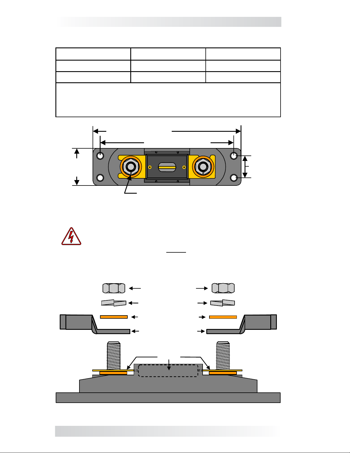
5/16 – 18 bolt w/ Hex nut (x2)
Requires 9/16" wrench
Figure 1, Small Fuse Block Dimensions
WARNING: During installation, incorrect stacking of the fuse
block hardware can create a highly resistive connection that
generates heat
. DO NOT place anything (i.e., washers)
between the fuse and either battery cable lug as this can
cause the fuse to overheat and blow open, resulting in a partial
melting of the fuse holder and cover. Before stacking, refer to
Figure 2.
Figure 2, Small Fuse Block Hardware Stacking
Fuse
Battery Cable
Lugs
Flat Washers
Lock Washers
Hex Nuts
Table 1, Fuse Selection
 Loading...