

Page 1
DC Load Breakers (Back Mount Type) Instruction Sheet
Magnum Energy, Inc.
2211 West Casino Rd.
Everett, WA 98204
www.magnumenergy.com
Introduction
The BR-DC75-BM and BR-DC100-BM are DC circuit breakers that can be used
as disconnects for charge controllers and DC loads. The breaker is either a
75-amp (PN: BR-DC75-BM) or a 100-amp (PN: BR-DC100-BM). Both have a
slotted bracket that allows them to be easily mounted to a mounting plate inside
the MP (Magnum Panel) and MMP (Mini Magnum Panel) system enclosures.
These circuit breakers are magnetic-hydraulic, back-mountable, general
purpose E-Frame type with front accessible pressure terminal connectors that
accept #14 through #0 AWG copper or aluminum wire.
Info: These breakers are not 100% continuous duty rated. To use
these breakers for continuous operation, they need to be derated
to 80%. For example, the BR-DC75-BM (75 amp) breaker can be
operated at 60 amps continuous (75 x .8 = 60 amp).
CAUTION: These breakers must be mounted in a vertical position
to meet the specifi ed trip current and trip delay curve.
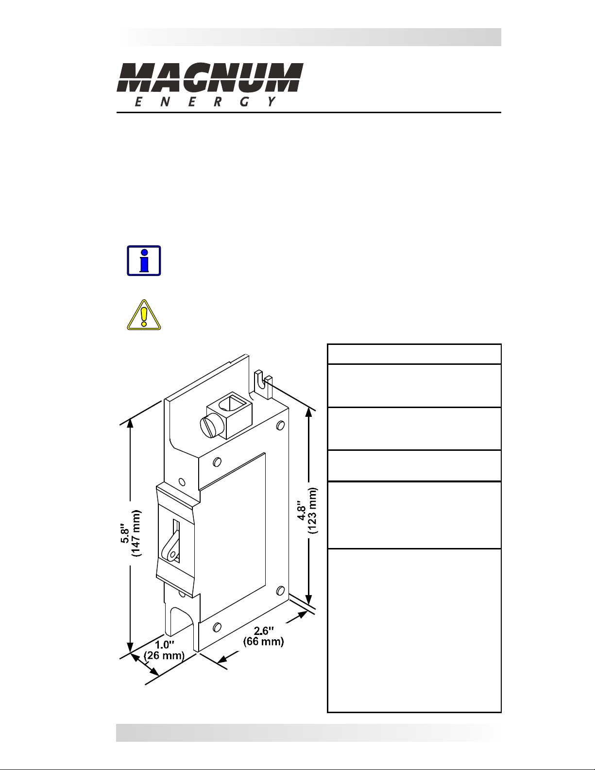
Sizes shown in
inches (mm)
Figure 1, Physical Dimensions
Specifi cations
Approvals
• UL 489 Listed
• CSA Certifi ed C22.2 No. 5
Interrupting Capacity
• 5,000 amperes at 125VDC
• 25,000 amperes at 65VDC
Trip Time Delay
• Delay 53 (DC long delay)
Recommended Torque:
• #14 to #18 AWG = 35 in. lbs.
• #8 AWG = 40 in. lbs.
• #6 to #4 AWG = 45 in. lbs.
• #3 to #0 AWG = 65 in. lbs.
Physical:
• Weight: ~9 oz. (255 grams)
• Dimensions: See Figure 1
• Terminals: front connected,
AL9CU dual-rated, pressure
terminals. Accepts #14 to #0
AWG copper or aluminum wire
(both 60° C and 75° C rated).
• Mounting: Attaches to back
mounting plate with #8-32 x 1/2”
(T20 head) Torx screws through
6/32 mounting inserts (torque to
6-8 in. lbs.).
Part Number: 64-0041 Rev C 1
Page 2

DC Load Breakers (Back Mount Type) Instruction Sheet
WARNING: During normal operation, terminals, busbars, and elec-
trical components inside the MMP/MP enclosure may be energized
- DO NOT TOUCH. Disconnect all power sources before removing the
cover. Failure to take action could result in physical harm.
Installation Steps:
Info: The MMP enclosure is shown in Figure 2, however the in-
stallation is similar in MP installations.
1. Remove the breaker front panel cover only after all power has been removed
from the MMP (Mini Magnum Panel) or MP (Magnum Panel) system.
2. Remove the DIN rail track on the breaker mounting plate by removing the
#8-32 x 3/8” (T15 head) Torx screws holding this track.
Info: The holes in the mounting plate — for the Torx screws that
hold the breakers — are NOT threaded. Prior to mounting the
breaker, use a power-driver to pre-thread the holes in the mounting plate with the self-threading Torx screws (T20 head) provided.
3. After the holes in the mounting plate have been pre-threaded, place the
back mount breaker(s) against the mounting plate and loosely secure them
using the two #8-32 x 1/2” (T20 head) Torx screws provided. Do not fully
tighten these Torx screws, that will be done in Step 5 after being aligned.
4. For each breaker installed, remove only the knockouts in the front panel
cover that are needed for the width of the breaker. Each breaker uses a 1”
opening, which requires removing 2 knockout slots (1 knockout = 1/2” slot).
5. Ensure each breaker aligns correctly into the spaces — made by the
knockouts removed from the front panel cover — by placing the front panel
cover over the DC breakers. If the fi t and alignment are correct, use a hand
driver to tighten the Torx screws to secure each DC breaker.
CAUTION: The slotted mounting brackets on the breaker are made
of plastic. DO NOT OVERTIGHTEN the Torx screws used to hold the
breaker to the mounting plate or the brackets may break. It is highly
recommended to use a hand driver to tighten the screws.
The DC breaker is now installed and ready to be wired to the DC circuit.
Remove DIN
rail and screw
breaker to
mounting plate.
Two DC breaker
mounting screws
( #8-32, use 1/2”
length minimum)
Back
mounted
DC breaker
(1” width)
Figure 2, Installing Back Mounted DC Breakers
2 © 2013 Magnum Energy, Inc.
 Loading...