

Page 1
AC Load Breakers Instruction Sheet
Magnum Energy, Inc.
2211 West Casino Rd.
Everett, WA 98204
www.magnumenergy.com
Introduction
The BR- AC30D and BR-AC60S are AC breakers that are used as the disconnect
switch and overcurrent protection device for the inverter’s AC input. These
circuit breakers come equipped with slots in the molded case for attaching
mounting brackets/feet, which allows them to be easily back -mounted to the
breaker mounting plate inside the MP (Magnum Panel) enclosure.
Depending on the part number, the breaker is either a 30 amp dual pole
(PN: BR-AC30D) or a 60 amp single pole (PN: BR-AC60S), general purpose
Square-D QOU™ type, back-mountable, AC circuit breaker.
WARNING: During normal operation the terminals, busbars, and
electrical components inside the MP may be energized - DO NOT
TOUCH. Disconnect all power sources before removing cover .
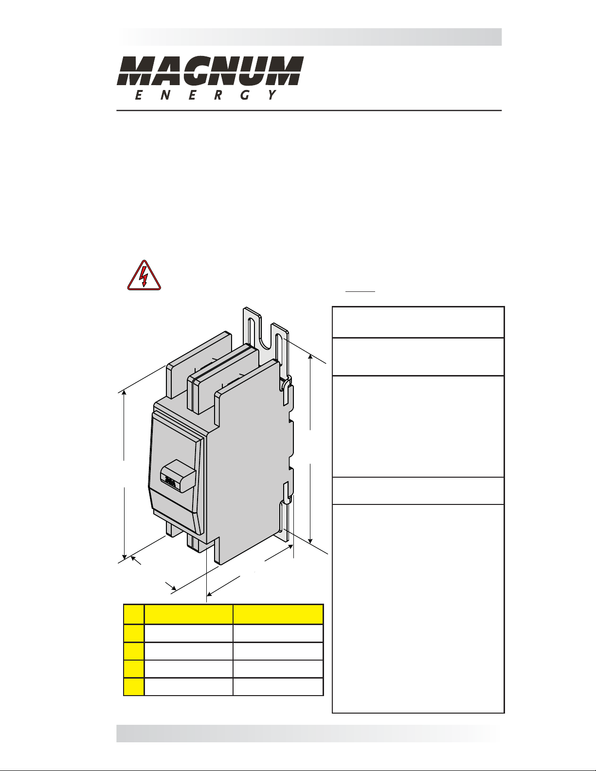
Square-D, Type QOU
Breaker Specifi cations
A
B
BR-AC30D
C
BR-AC30D BR-AC60S
A 4.1” (10.4 cm) 4.1” (10.4 cm)
B 1.5” (3.8 cm) 0.75” (1.9 cm)
C 2.4” (6.1 cm) 2.4” (6.1 cm)
D 4.6” (11.7 cm) 4.6” (11.7 cm)
Figure 1, Physical Dimensions
D
Approvals:
• UL489 Listed - CSA C22.2 #5.1
Certifi ed
Continuous Current:
• QOU circuit breakers should be
applied (per the NEC) to carry 80%
of their continuous current ratings
as indicated on the handle of each
circuit breaker. BR-AC30D dual pole
= 30 amps (24 amps derated); BRAC60S single pole = 60 amps (48
amps derated)
Recommended Torque:
• Using T erminal Screw = 43 in. lbs.
Physical:
• Weight: BR-AC60S = ~5.9 oz.
(167.3 g); BR-AC30D = ~12 oz.
(340.2 g)
• Terminals: Box-type lugs with
slotted terminal screws. UL listed
and CSA certifi ed to accept solid or
stranded #14 to #2 AWG copper or
aluminum conductors. These lugs
are UL listed to be used with wire
rated at 140°F, 167°F and 194°F
(60°C, 75°C and 90°C), sized
according to the NEC 176°F (75°C)
temperature rating.
• Mounting: Attaches to the breaker
mounting plate with #8-32 x 1/4”
(T20 drive) Torx screws using the
included fi eld installable mounti
brackets/feet.
ng
PN: 64-0043 Rev A 1
Page 2
AC Load Breakers Instruction Sheet
Installation Steps:
1. Remove the MP’s breaker face plate cover only after all power has been
removed from the MP (Magnum Panel) system.
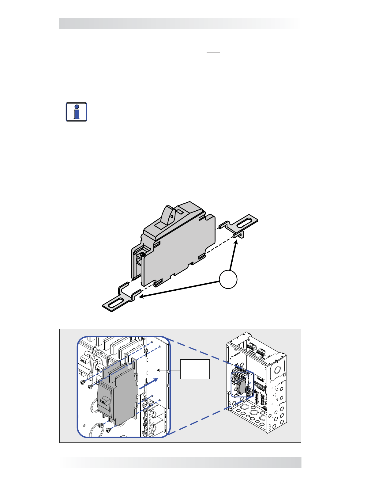
2. Install the mounting feet (A) on each end of the circuit breaker (Figure 2).
3. While holding the AC breaker against the MP’s mounting plate, align the
breaker’s mounting holes with the enclosure’s mounting holes (Figure 3).
Note: AC breakers are installed in the left enclosure of a MP dual enclosure.
Info: The holes in the mounting plate — for the Torx screws that
hold the breakers — are NOT pre-threaded. Prior to mounting the
breaker, pre-thread the holes using a power-driver and the selfthreading Torx screws (T20 drive) that are provided.
4. Use the supplied #8-32 x 1/4” T20 screws to hold the AC breaker in place.
Do not fully tighten the screws, that will be done in the next step after ensuring
proper alignment with the MP’s breaker face plate cover.
5. Place the MP’s face plate cover over the AC breakers to ensure each
breaker aligns correctly into the spaces (knockouts removed from the face
plate cover). If the fi t and alignment are correct, use a hand driver to tighten
the Torx screws to secure each AC breaker.
The AC breaker is now ready to be wired to the inverter and the AC loads.
NOTE: The BR-AC60S
has single slotted mounting feet (x2); BR-AC30D
has dual slotted mounting feet (x2)
Figure 2, Attaching Mounting Feet to AC Load Breaker
BR-AC60S
A
Breaker
Mounting
Plate
Figure 3, Installing AC Load Breaker Within a MP Single Enclosure
2 © 2011 Magnum Energy, Inc.
 Loading...