

Page 1

MAGNUM Standard
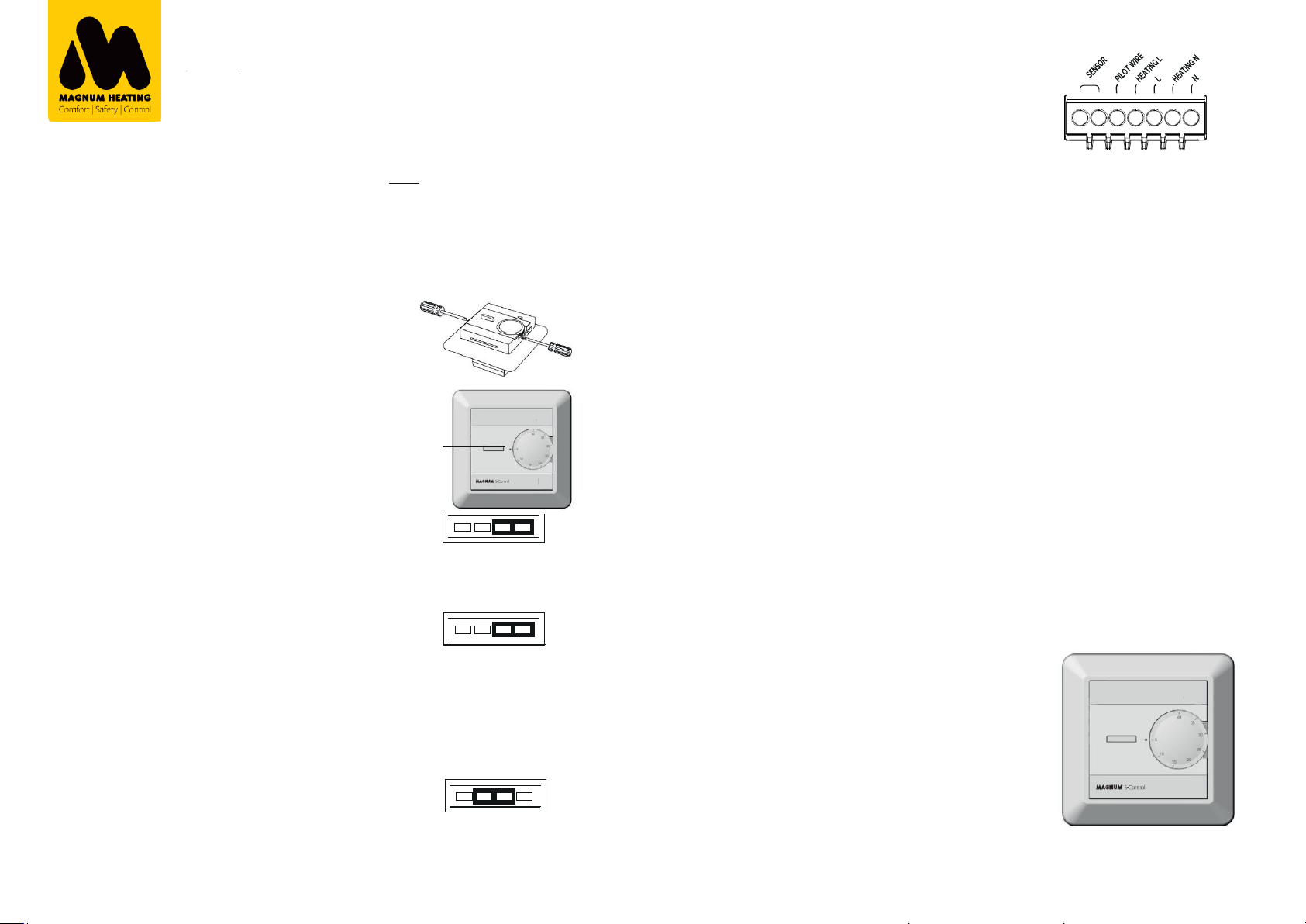
3. Connecting the thermostat
On/Off
Thermostat
Installation
manual
PLEASE READ THIS MANUAL CAREFULLY
BEFORE INSTALLATION, AND STORE WITH
OTHER WARRANTEE FORMS.
Bi-LED diode
Adjustment wheel
The termostat must be connected to the power source according to
the connection diagram. All heating systems must be equipped with a
residual current disrupter with 30mA. Max load for the thermostat is
16A/3600W at 230V. If the load is higher, the thermostat must be
connected to a contactor. The thermostat does not have galvanic
insulation between high and low current. The sensor must therefore
be considered as live (230V) and needs to be installed in accordance
with the rules for high current installations and national installation
requirements.
Caution: When reattaching the thermostat cover, make sure the ventila-
Torque: Max. 2Nm
Clamp 1+ 2Sensor - Floor sensor
The MAGNUM Standard Control is an electronic thermostat
with four functions: Room sensor, floor sensor, power regulator
and room sensor with max./min. limiter. This thermostat can also
be set up for setback temperature.
tion on the top and bottom of the thermostat is not covered up.
4. Setback temperature
The Multireg thermostat does not have a built-in setback temperature
Clamp 3: Pilot wire (connected to L for
setback temperature)
Clamp 4: Heating L
Clamp 5: L
1. Startup
Remove the adjustment wheel with a screwdriver. The front
cover can the be removed by pushing in the locking clips on
each side of the thermostat (as shown in fig.2). Be careful when
doing this in order not to damage the thermostat. When the
thermostat has been connected to the power source, push the
on/off button.
Never dismantle the thermostat when the power is switched on.
2. Sensor choice
When choosing a sensor type, the thermostat should not be
connected to a power source.
• Floor sensor (standard)
Jumper placement: Covering the two pins on the left.
Application: The temperature is regulated by the floor sensor.
• Room sensor
Jumper placement: Covering the two pins in the right
Application: The temperature is regulated by the room sensor.
• Room sensor with limiter
Jumper placement: Covering the two pins on the right + the
floor sensor connected
Application: The temperature is regulated by the room sensor,
but the floor sensor overrides the room sensor if the floor
temperature exceeds the maximum limit temperature. The limiter
can be regulated between 20°C and 30°C. For parquet flooring, a
maximum of 27°C is recommended by most flooring manufac-
turers. Please follow the recommendations provided by your
manufacturer.
• Power regulator
Jumper placement: Covering the two center pins
Application: The effect regulator has a 30 min cycle. The desired
on/off interval can be set from 0 to 10, where each level
increases the on-time by 3 minutes.
Example: When the thermostat is set to level 3, the heating
element is switched on for 9 minutes, then off for 21 minutes in
the 30 minute cycle. If the thermostat is set to level 6, the
heating element is switched on for 18 minutes, then off for 12
minutes.
Fig.
1
LED lampje
option, but by connecting an external timer to the 3 and 4 clamps, the
temperature can be lowered by 3°C at desired times.
5. Calibrating the temperature
When connecting the floor heating system for the first time, the temperature should be set at a maximum of 15°C to 20°C. The thermostat
should be calibrated after 2-3 days. Pull out the adjustment wheel
carefully (without turning it) until it comes loose. Use a thermometer to
check the actual temperature, and push the adjustment wheel back onto
the thermometer in accordance with the measured temperature. If the
floor heating has been switched off during the summer, this procedure
should be repeated when it is switched back on.
6. Bi-LED diode
• Green light when the thermostat is in a standby mode.
• Constant red light when the relay is engaged and the power is on.
• Blinking red light when there is a sensor malfunction or the
floor sensor is disconnected.
7. Technical data
Voltage 230 VAC AC ± 15% 50 Hz
Max. load 3600W (resistive load)
Max. current 16
Amp Power consumption
0,5W
IP-class IP 21
Power regulator Time cycle: 0-30 min
Min/Max inst. temp. -20°C - +60°C
Min/Max oper. temp. 0° - 50°C
Temperature intervals Floor sensor: 5°C - 40°C
Room sensor 5°C - 40°C
Hysteresis 0.5°C
Sensor values 0°C 29,1 Кohm
10°C 18,6 Кohm
15°C 15,1 Кohm
20°C 12,2 Кohm
25°C 10,0 Kohm
Switch 2-pole switch
Colors White RAL 9010 (5430333)
White RAL 9003 (5430444)
Floor sensor Length 3 meters. The cable can be extended
10 meters by using a proper installation cable.
Clamp 6: Heating N
Clamp 7: N
1 2 3 4 5 6 7
Page 2
MAGNUM Standard
3.Подключение
Вкл/Выкл Термостат
Инструкция по
установке
MAGNUM S-Control - это электронный термостат с 4
функциями; комнатный датчик, датчик пола, регулятор
мощности и датчик помещения с датчиком пола в качестве
предельной функции. Э тот термостат также можно
настроить на пониженную температуру.
1. Установка и запуск
Снимите ручку регулировки температуры с помощью
отвертки. Затем крышку термостата можно снять, нажав на
монтажные зажимы с обеих сторон термостата (показано на
рисунке 2). Это должно быть сделано осторожно, чтобы
предотвратить возможные повреждения. После того, как
термостат полностью подключен, можно нажать кнопку
включения-выключения для активации. Никогда не
разбирайте термостат, если он находится под напряжением.
2. Выбор датчика
Термостат должен быть выключен для выбора датчика.
• Датчик пола (стандарт)
Положение перемычки: ВЛЕВО
Функция: температура контролируется на основании
датчика пола.
• Комнатный датчик
Положение перемычки: ПРАВО
Функция: температура контролируется на основе
комнатного датчика.
• Комнатный датчик с ограничителем.
Расположение перемычки: закрытие двух штифтов справа +
датчик пола подключен
Применение: температура регулируется комнатным
датчиком, но датчик пола перекрывает комнатный датчик,
если температура пола превышает максимальную
предельную температуру. Ограничитель может
регулироваться от 20 ° C до 30 ° C. Для паркета
большинство производителей пола рекомендуют максимум
27 ° C. Пожалуйста, следуйте рекомендациям вашего
производителя.
• Регулятор мощности
Расположение перемычки: закрытие центральных штифтов
Применение: Регулятор имеет цикл 30 минут. Требуемый
интервал включения / выключ ения может быть установлен
от 0 до 10 где каждый уровень увеличивает время
включения на 3 минуты.
Пример: Когда термостат установлен на уровень 3,
нагревательный элемент включается на 9 минут, затем
выключается на 21 минуту в 30-минутном цикле. Если
термостат установлен на уровень 6, нагревательный
элемент включается на 18 минут, затем выключается на 12
минут.
LED диод
Колес ико
Вкл/Вы кл
Рис.1
g.2
Термостат должен быть подключен к источнику
питания согласно схеме подключения. Все системы
отопления должны быть оснащены УЗО на 30 мА.
Максимальная нагрузка для термостата составляет 16 А
/ 3600 Вт при 230 В. Если нагрузка выше, термостат
должен быть подключен к контактору. Термостат
работает на 230 Вольт и должен быть установлен и
подключен в соответствии со стандартами NEN1010.
Порядок проводов на клеммах 1 и 2 (датчик) и 4 и 6
(нагрев) не важен.
Внимание: убедитесь, что вентиляционные решетки
сверху и снизу свободны при замене рамы и крышки.
4. Понижение температуры
Термостат не имеет встроенной понижающей
температуры, но при подключ ении внешнего таймера к
клеммам 3 и 4 активируется понижающая температура
минус 3 градуса.
5. Калибровка
При первом подключении системы подогрева пола
температура должна быть установлена не более 15 –20°C.
Термостат следует откалибровать через 2-3 дня.
Осторожно вытяните регулировочное колесо (не
поворачивая его), пока оно не ослабнет. Используйте
термометр, чтобы проверить фактическую температуру,
и наденьте регулировочное колесо обратно на термометр
в соответствии с измеренной температурой. Если
отопление пола было отключено летом, эту процедуру
следует повторить при повторном включении.
6. LED диод
• Зеленый: термостат находится в режиме ожидания
и не работает.
• Непрерывный красный: термостат активен и
нагревается.
• Мигает красным: датчик неисправен или не
подключен. Проконсультируйтесь с вашим
поставщиком или службой поддержки.
7. Технические данные
Напряжение 230 В ± 15% 50 Гц
Макс. нагрузка 3600 Вт / 16 A
Потребление энергии 0,5 Вт
Класс защиты IP21
Регулятор мощности 30 минутный цикл
Мин./Макс.температура (установки) от - 20 до + 60oC
Мин./Макс.температура (рабочая) от 0 до + 50oC
Температурный интервал от +5 до + 40oC
Выключатель 2-х п олюсный
Цвет белый RAL9010
Датчик пола длина 3 метра. Датчик пола можно
как удленить, так и укоротить.
Клемма 1+2: Датчик температуры
Клемма 3: Контрольный провод (только для
понижения температуры)
Клемма 4: Нагрузка L
Клемма 5: Фаза L
Клемма 6: Нагрузка N
Клемма 7: Нейтраль N
1 2 3 4 5 6 7
 Loading...