

Magnum Mx-UTR-L3 Installation Manual
1
Magnum Innovations 5675 Hudson Industrial Pkwy, Suite 3 Hudson, OH 44236 phone 330.915.2382 fax 330.529.5279 www.magnum-innovations.com info@magnum-innovations.com
Product Installation Guide
Two Channel Lighting Control Module (0-10V)
Mx-UTR-L3
1] Description
4] Equipment Needed for Installation
5] Planning for Installation
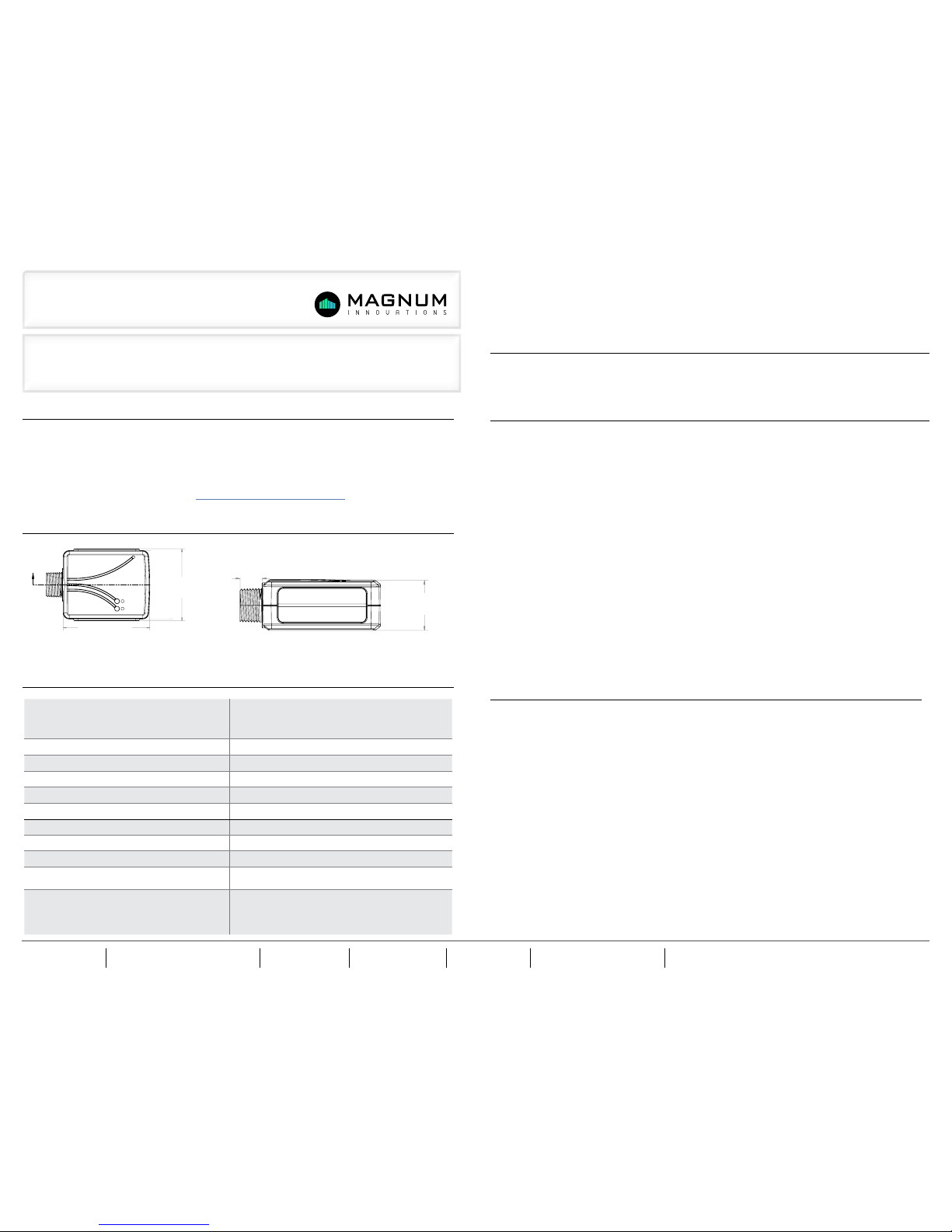
2] Dimensions
The Mx-UTR-L3 Lighting Control Module responds to a variety of wireless EnOcean devices to control and dim LED drivers,
fluorescent ballasts, or other switchable loads. The Mx-UTR-L3 oers bi-directional, ON/OFF and 0-10V dimming control when
combined with a wireless light switch or automatic shut-o when combined with a wireless occupancy sensor. Additionally,
the Lighting Control Module can perform occupancy-based setback dimming and self -contained daylight h arvesting func-
tions. The Mx-UTR-L3 can be paired to compatible devices manually, and for more sophisticated configuration the MES
software airConfig tool is available for download at http://download.magnum-innovations.net.
• Electrical tape • Screwdriver • Wire nuts
* For advanced configuration, additional equipment is required, including laptop, USB 300U (available for order from MES)
and AirConfig, which is available for free download at http://download.magnumes.net
• Take a moment to prepare for installation and ensure optimal communications with other system components in the space
• To assess signal strength prior to and during installation, you can utilize the following:
- MES’s free range testing tool “AirSpy”, available at http://download.magnumes.net. Requires USB 300U.
- If utilizing Mx-EBOXs (BACnet to IP) gateway, utilize BACnet point available for signal strength
(RSSI)
• Always utilize a qualified installer
• Straighten antenna out and away from any surrounding metal
• Create separation distance between interfering electronics such as fluorescent tube ends, ballasts, electronic
transformers, and motors. Avoid mounting inside of metal enclosures.
• Obstructions of metal, concrete and dense building materials will reduce the range. Mount higher and away from
obstructions to maximize range.
In applications using HVAC units a Relay Contactor is required for the units per AMP rating.
If following the standard, manual pairing process, please refer to the “Learn In Procedure” section at the end of this
document. If manual with default settings is the preferred method of commissioning, it is recommended this process be
done prior to installation, unless access to buttons and device is possible.
For advanced configuration using AirConfig, install Mx-UTR-L3 as discussed and perform commissioning process with
device installed. Make sure that device is still within wireless range.
6] Installation
COMMON APPLICATIONS:
WARNING: TO AVOID RISK OF FIRE, SHOCK, OR DEATH, TURN OFF POWER AT CIRCUIT BREAKER OR FUSE AND
VERIFY THAT IT IS OFF BEFORE INSTALLATION BEGINS. MAKE SURE THAT IT REMAINS OFF UNTIL INSTALLA-
TION IS COMPLETE. PLEASE BE AWARE THAT WITH THIS VERSION OF THE PRODUCT, IT IS POSSIBLE TO HAVE
MULTIPLE BRANCH CIRCUITS FEEDING THE RELAY RECEIVER.
NOTE: Read the WARNINGS AND CAUTIONS section before beginning these installation options. Read all steps for this
option before taking any action to install receiver.
1) For in-wall installation, a wiring box must be used. For ceiling installation make wire connections inside a junction box.
Ensure that the temperature in the ceiling box will not exceed 50 degrees C. For best wireless signal performance install
receiver in plastic box away from floor and away from metal objects.
2) Connect wires as shown in Figure A. Twist wire nuts on clockwise making sure no bare wires show. Wrap connections
with electrical tape.
3) Stow all wires in wiring box.
4) Restore power and follow instructions under the “Setting Up Your Device via airConfig” section at the end of this
document, or follow manual pairing procedures to use default settings.
5) To test that the device is working, press and release SW1. This will toggle ON/OFF. (If receiver is not working, review
wiring and programming instructions).
6) Finish any installation of fixture or wall switch.
3] Technical Specifications:
Part Numbers (Frequency Dependant) M9-UTR-L3 (902 MHz - North America)
M8-UTR-L3 (868 MHz - Europe and China)
MJ-UTR-L3 (928 MHz - Japan)
Range 150 feet (50-150 typical)
EnOcean Profile (2x) A5-38-08 Type 0x02 Dimming
Input Voltage 120/277 VAC
Max Switched Power 3300W @ 277VAC
Max Switched Current 20A
Max Switched Voltage 120/277 VAC
Relay Output 2 N.O. and 2 Common contact
Dimmer Output (2x) 0-10V, 30 mA (sinking drivers)
Ambient Operating Temperature
0-55°C for 3300 W load @ 277 VAC
(Mx-UTR-L3 & Mx-UTR-L2: 37°C for 3300 W load @ 277 VAC)
Certifications ETL/Intertek - UL 244A
FCC (United States) SZV-TCM3XXX
IC (Canada) 5713A-TCMXXX
DLC
2.439
2.939
2.319
AA
73.74°
.071
2.26°
2.94°
SECTION
A-A
D
C
5
4
3
2
1
2.939”
(74.65 mm)
2.319”
(58.9 mm)
2.439
2.939
2.319
AA
73.74°
.071
2.26°
2.94°
SECTION
A-A
1.250
.900
.550
D
C
B
5
4
3
2
1
1.25”
(31.75 mm)
.55”
(13.97 mm)
2
Magnum Innovations 5675 Hudson Industrial Pkwy, Suite 3 Hudson, OH 44236 phone 330.915.2382 fax 330.529.5279 www.magnum-innovations.com info@magnum-innovations.com
Product Installation Guide
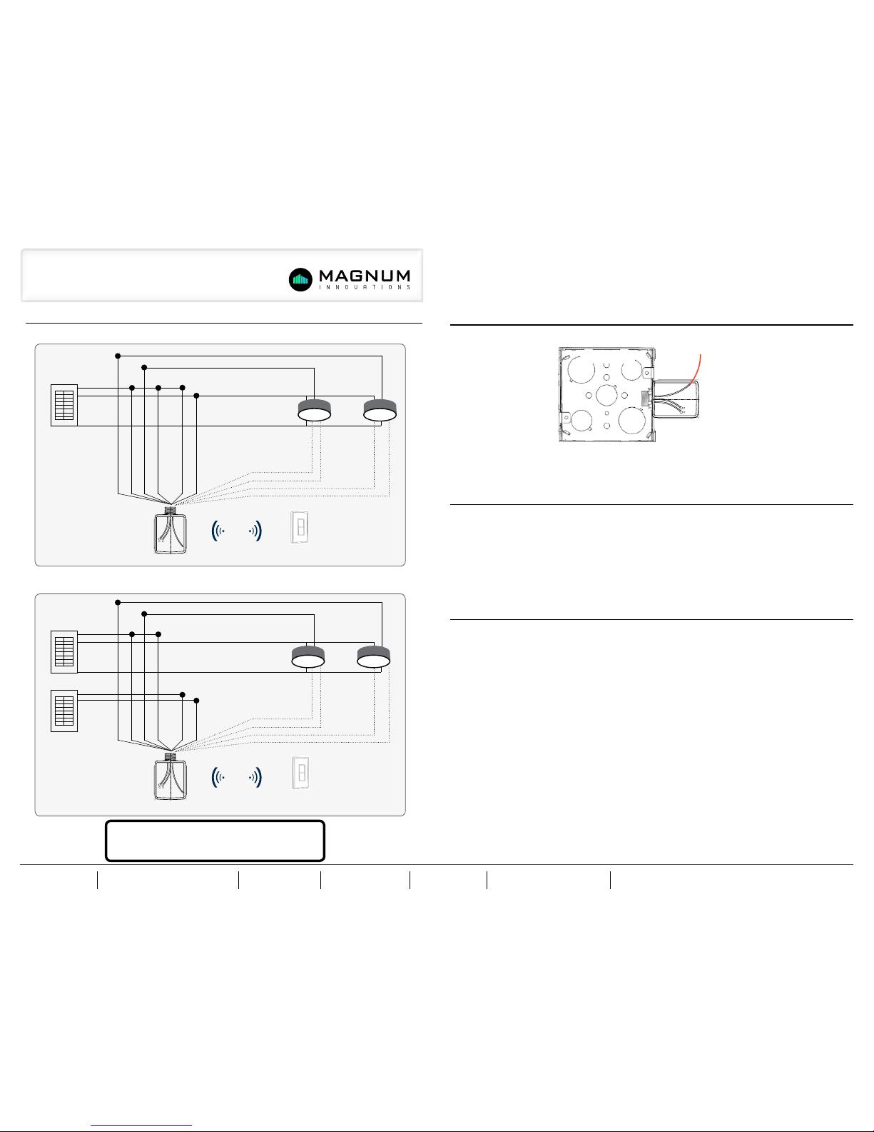
7] Wiring Diagrams
8] Wireless Mounting Options
9] Compatible Devices
10] Warnings & Cautions
FIGURE A: Single Power Source
FIGURE B: Dual Power Source
• The Mx-UTR-L3 can be controlled using a variety of other devices, including:
• Mx-ML2 (Occ / Lux Sensor) • Mx-EOSC (Ceiling Mounted Occ Sensor)
• Mx-EOSW (Wall Mounted Occ Sensor) • Mx-SW1 (Wireless Single Rocker Switch)
• Mx-SW2 (Wireless Double Rocker Switch) • Mx-ESRP (Wireless Single Rocker Switch)
• Mx-EDRP (Wireless Double Rocker Switch) • Mx-MRC1 (Wireless Window / Door Sensor)
• Mx-EDWS (Wireless Window / Door Sensor) • Mx-ECKU (Wireless Key Card Switch)
• Mx-eBox (BACnet IP Gateway) • Mx-AP2 (Access Point)
• HIGH VOLTAGE: A qualified installer or electrician must install this device. Follow all applicable electrical codes for installation.
• Relays and receivers are intended for INDOOR use only, in dry locations with permanently installed fixtures
• This device is suitable for a circuit capable of delivering not more than 20 AMP maximum
• Be sure not to install this device in locations where the units are in close proximity to the light bulbs or other sources of
heat, particularly with high wattage loads.
• When using relays to switch a motor, overload and over current protection sized for the motor load should be provided at
the branch circuit feeder supplying the motor in accordance with the NEC or CEC, as applicable for the installation location
• The maximum over current protection required for the branch circuit supplying this product is 20 AMPS. When one or
more motors are installed and not internally protected then an overload protective device sized at not more than 115% of the
motor full load AMPS should be installed for each motor.
• When using devices to control motors and HVAC equipment, which don’t respond well to the ON/OFF cycling that occurs
in the “learn” mode, it is advised to configure the receivers without the motor or HVAC load connected. Instead, program the
products in advance by connecting them to a light or to another load that is safe when toggling on and o.
OUTSIDE JUNCTION BOX
THREADED
WIRELESS
RELAY
JUNCTION BOX
2.439
2.319
AA
2.26°
SECTION
A-A
D
C
5
4
3
2
1
BREAKER PANEL
HOT BLACK
AC POWER BLACK
AC POWER WHITE
LIGHT
FIXTURES
GROUND GREEN
RELAY 2:
BLUE WITH RED STRIPE
RELAY 1:
BLUE WITH BLACK STRIPE
RELAY 2:
RED WITH GREY STRIPE
RELAY 1:
BLACK WITH BLUE STRIPE
AC POWER IN
BLACK
0-10 V OUTPUT: GREY (-)
0-10 V OUTPUT: GREY WITH RED STRIPE (-)
0-10 V OUTPUT: VIOLET (+)
0-10 V OUTPUT: VIOLET WITH RED STRIPE (+)
AC POWER IN
WHITE
WIRELESS CONTROL
SIGNAL UP TO 150 FT
BATTERY-FREE
WIRELESS SWITCHES
NEUTRAL WHITE
GROUND
GREEN
MX-UTR-L3
R.563
R.320
.060
.060
73.74°
.071
2.26°
2.94°
.044
.049
.824
SECTION
A-A
C
D
8
7
6
5
4
BREAKER PANEL
BREAKER PANEL
HOT BLACK
AC POWER BLACK
AC POWER WHITE
LIGHT
FIXTURES
GROUND GREEN
RELAY 2: BLUE WITH
RED STRIPE
RELAY 1: BLUE
WITH BLACK STRIPE
RELAY 2: RED WITH
GREY STRIPE
RELAY 1: BLACK
WITH BLUE STRIPE
AC POWER IN
BLACK
0-10 V OUTPUT: GREY (-)
0-10 V OUTPUT: GREY WITH RED STRIPE (-)
0-10 V OUTPUT: VIOLET (+)
0-10 V OUTPUT: VIOLET WITH RED STRIPE (+)
AC POWER IN
WHITE
WIRELESS CONTROL
SIGNAL UP TO 150 FT
BATTERY-FREE
WIRELESS SWITCHES
NEUTRAL WHITE
GROUND
GREEN
MX-UTR-L3
R.563
R.320
.060
.060
73.74°
.071
2.26°
2.94°
.044
.049
.824
SECTION
A-A
C
D
8
7
6
5
4
NOTE: Magnum Wireless device antenna cannot be
enclosed inside a metal box. Wireless range will be
greatly limited with enclosed antenna.
 Loading...