

Page 1
SUBMERSIBLE CONTRACTOR PUMP
MSC 2101 • MSC 2202 • MSC 2302
MSC 3202 • MSC 3302
OPERATING/PARTS MANUAL
Page 2

INTRODUCTION
This manual provides information and procedures to safely operate and maintain the pump. For your own safety
and protection from physical injury, carefully read, understand, and observe the safety instructions described in this
manual. Keep a copy of this manual with the unit at all times. Additional copies are available from Magnum Products
LLC, or can be found at www.m-p-llc.com. The information contained in this manual was based on machines in
production at the time of publication. Magnum Products LLC reserves the right to change any portion of this information
without notice.
DO NOT MODIFY or use this equipment for any application other than which it was designed for.
MAGNUM PRODUCTS LLC
215 Power Drive • Berlin, WI 54923
U.S.A.
Phone: 920-361-4442
FAX: 920-361-4416
Toll Free: 1-800-926-9768
www.m-p-llc.com
For technical or parts QUESTIONS, please contact Magnum Products’ Customer Support or
Technical Support team at 920-361-4442 or toll free at 1-800-926-9768. Please have your
serial number available.
To ORDER SERVICE PARTS, please contact the dealer from which you purchased the unit,
or call Magnum Products to locate a dealer in your area.
Unit Model Number:_____________________________________
Unit Serial Number: _____________________________________
2
Page 3

TABLE OF CONTENTS
Page
INTRODUCTION ................................................................................................................................... 2
TABLE OF CONTENTS ......................................................................................................................... 3
SAFETY NOTES .................................................................................................................................... 4
OPERATING SAFETY ........................................................................................................................... 4
UNIT SERIAL NUMBER LOCATION ..................................................................................................... 5
SPECIFICATIONS ............................................................................................................................5 - 6
OPERATING THE PUMP ...................................................................................................................... 7
CLEANING THE PUMP ......................................................................................................................... 7
STORING THE PUMP ........................................................................................................................... 7
COMPONENT LOCATIONS - MSC 2101, MSC 2202 & MSC 3202 ..................................................... 8
COMPONENT LOCATIONS - MSC 2302 & MSC 3302 ........................................................................ 9
UNIT ASSEMBLY AND PARTS - MSC 2101, MSC 2202 & MSC 3202 ........................................ 10 - 11
UNIT ASSEMBLY AND PARTS - MSC 2302 & MSC 3302 ...........................................................12 - 13
WIRING DIAGRAM - MSC 2101 .......................................................................................................... 14
WIRING DIAGRAM - MSC 2202, MSC 2302, MSC 3202 & MSC 3302 .............................................. 15
3
Page 4
This is the safety alert symbol. It is used to alert you to potential personal injury hazards.
Obey all safety messages that follow this symbol to avoid possible injury or death.
DANGER
SAFETY NOTES
WARNING
This manual contains DANGERS, WARNINGS, CAUTIONS, NOTICES and NOTES which must be
followed to prevent the possibility of improper service, damage to the equipment, personal injury or death.
The following formatting options will apply when calling the readers attention to the DANGERS, WARNINGS, CAUTIONS, NOTICES and NOTES.
INDICATES A HAZARDOUS SITUATION WHICH, IF NOT AVOIDED,
WILL RESULT IN DEATH OR SERIOUS INJURY.
WARNING
Indicates a hazardous situation which, if not avoided, could result
in death or serious injury.
CAUTION
Indicates a hazardous situation which, if not avoided, may result in minor
or moderate injury.
NOTICE
Indicates a hazardous situation which, if not avoided, may result in
property or equipment damage.
Note: Notes contain additional information important to a procedure and will be found within the regular
text body of this manual.
OPERATING SAFETY
Before using the pump be sure to read and understand all of the instructions! This equipment was designed
for specific applications; DO NOT modify or use this equipment for any application other than which it was
designed for. Equipment operated improperly or by untrained personnel can be dangerous! Read the
operating instructions and familiarize yourself with the location and proper use of all instruments and
controls. Inexperienced operators should receive instruction from someone familiar with the equipment
before being allowed to operate the pump. The following points should be practiced at all times:
• NEVER start a unit in need of repair.
• NEVER operate the pump if any of the following conditions exist during operation:
1. Sparking occurs.
2. Combustible surface is present.
3. Protective covers are loose or missing.
Never pump volatile or corrosive chemicals or solutions with this pump.
These fluids could create serious health and environmental hazards. High
pressure increases the chance of pump explosion which may result in
serious personal injury.
4
Page 5
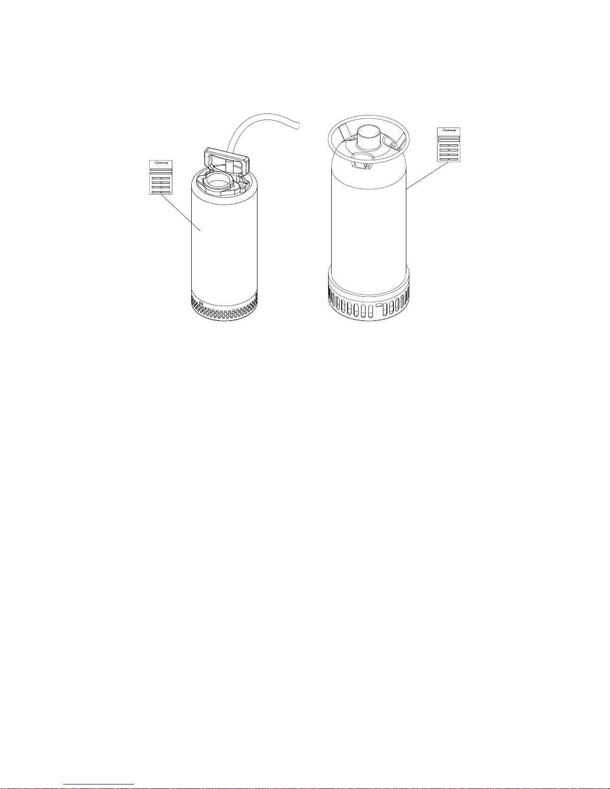
UNIT SERIAL NUMBER LOCATION
Refer to the location illustrated below to find the unit ID tag. Important information, such as the unit serial number
and model number are found on this tag. Record the information from this tag, so it is available if the tag is lost or
damaged. When ordering parts or requesting technical service information, you may be asked to specify this
information.
Unit ID Tag
215 Power Drive • Berlin, WI 54923
1-800-926-9768
MODEL
MSC 3302
SERIAL NUMBER
000000
WEIGHT
kglbs.
FLOW
Lpmgpm
POWER
kWhp
Unit ID Tag
215 Power Drive • Berlin, WI 54923
1-800-926-9768
MODEL
MSS 2101
SERIAL NUMBER
000000
WEIGHT
kglbs.
FLOW
Lpmgpm
POWER
kWhp
TOTAL HEAD
mft.
DO NOT RUN PUMP DRY!
TOTAL HEAD
mft.
DO NOT RUN PUMP DRY!
SPECIFICATIONS
Read this manual carefully before attempting to use this pump. The potential for property damage, personal injury
or death exists if this equipment is misused or installed incorrectly.
MAGNUM MODEL MSC 2101 MSC 2202 MSC 2302
Motor Type................................................. 1 Ø, 60 hz .........................1 Ø, 60 hz.........................1 Ø, 60 hz
Amperage Range (Min. - Max.)* ................ 9.7 - 12.6A ........................7.7 - 11.8A........................10.4 - 16.2A
Voltage ....................................................... 120V .................................240V.................................240V
Pump Output
Discharge Diameter ................................... 2 in. (50 mm)..................... 2 in. (50 mm)....................2 in. (50 mm)
Maximum Head.......................................... 59.1 ft. (18 m) ...................72 ft. (22 m)......................89 ft. (27 m)
Maximum Discharge .................................. 79.3 gpm (300.09 Lpm) ....119 gpm (450.33 Lpm) .....132 gpm (499.53 Lpm)
Power......................................................... 1 hp (746 W) ..................... 2 hp (1491 W) ..................3 hp (2237 W)
Solids Handling Capacity ........................... .2 in. (6 mm)...................... .4x1.4 in. (10x35 mm) .......4x1.4 in. (10x35 mm)
Weights and Dimensions
Dry Weight ................................................. 46 lbs. (21 kg)...................81 lbs. (37 kg) ..................110 lbs. (50 kg)
Shipping Weight......................................... 52 lbs. (24 kg) ...................83 lbs. (38 kg) ..................112 lbs. (51 kg)
Maximum Diameter.................................... 7 in. (180 mm)................... 9 in. (228 mm) ..................9 in. (228 mm)
Maximum Height ........................................ 18 in. (457 mm)................. 26 in. (650 mm)................26 in. (670 mm)
Cable Length.............................................. 20 ft. (6 m) ........................33 ft. (10 m)......................33 ft. (10 m)
Other Specifications
Cable Diameter .......................................... 14AWG ............................. 12AWG.............................12AWG
Impeller Material ........................................ HCr ...................................HCr...................................HCr
Impeller Type ............................................. Semi-open ........................ Semi-open ........................Semi-open
Strainer Material......................................... HCr ...................................HCr...................................HCr
Seal............................................................ Silicone Carbide Mech. .....Silicone Carbide Mech. ....Silicone Carbide Mech.
Electric Plug Included ................................ Yes.................................... No.....................................No
*Amperage varies upon head and flow.
SPECIFICATIONS ARE SUBJECT TO CHANGE WITHOUT NOTICE.
5
Page 6

SPECIFICATIONS
Read this manual carefully before attempting to use this pump. The potential for property damage, personal injury
or death exists if this equipment is misused or installed incorrectly.
MAGNUM MODEL MSC 3202 MSC 3302
Motor Type................................................. 1 Ø, 60 hz .........................1 Ø, 60 hz
Amperage Range (Min. - Max.)* ................ 8.1 - 10.7A ........................13.4 - 16.6A
Voltage ....................................................... 240V .................................240V
Pump Output
Discharge Diameter ................................... 3 in. (76 mm)..................... 3 in. (76 mm)
Maximum Head.......................................... 52 ft. (16 m) ......................66 ft. (20 m)
Maximum Discharge .................................. 172 gpm (650.9 Lpm) .......211 gpm (798.49 Lpm)
Power......................................................... 2 hp (1491 W) ................... 3 hp (2237 W)
Solids Handling Capacity ........................... .4x1.4 in. (10x35 mm) ........4x1.4 in. (10x35 mm)
Weights and Dimensions
Dry Weight ................................................. 91 lbs. (41 kg)...................111 lbs. (50 kg)
Shipping Weight......................................... 94 lbs. (42 lbs.) ................. 114 lbs. (52 kg)
Maximum Diameter.................................... 9 in. (228 mm)................... 9 in. (228 mm)
Maximum Height ........................................ 26 in. (650 mm)................. 26 in. (670 mm)
Cable Length.............................................. 33 ft. (10 m) ......................33 ft. (10 m)
Other Specifications
Cable Diameter .......................................... 12AWG ............................. 12AWG
Impeller Material ........................................ HCr ...................................HCr
Impeller Type ............................................. Semi-open ........................ Semi-open
Strainer Material......................................... HCr ...................................HCr
Seal............................................................ Silicone Carbide Mech. .....Silicone Carbide Mech.
Electric Plug Included ................................ No .....................................No
*Amperage varies upon head and flow.
SPECIFICATIONS ARE SUBJECT TO CHANGE WITHOUT NOTICE.
6
Page 7

OPERATING THE PUMP
WARNING
1. Connect the discharge hose with the proper fittings.
2. Place the pump in the water. Lower by attaching a strong rope to the handle. The pump should be placed on a
flat, hard surface in at least 2 inches of water.
WARNING
Never lower or move the pump with the electrical cord. Damage to the cord or cord
seal could result in equipment damage and/or electrocution.
NOTICE
Do not install the pump on clay, dirt, or sand surfaces. Small stones, gravel, sand, and mud can clog the pump and
reduce the performance or cause malfunction of the pump. If necessary, place the pump on a concrete block or slab
to prevent the pump from sinking.
3. Connect the grounding-type plug to an outlet.
4. The pump should begin to cycle. To ensure proper operation, observe the pump to make sure it has enough
water to avoid cavitation.
Never operate a pump or pump motor with wet hands. Never stand on a wet or damp
surface when operating the pump. Doing so could result in equipment damage or
personal injury.
WARNING
To prevent overheating, always keep the pump completely submerged when running
continuously. Running the pump continuously while not submerged could result in
equipment damage.
CLEANING THE PUMP
After running the pump, wash the pump in clean water. Keep inlet screens clean at all times, and always check the
screens before each use.
STORING THE PUMP
Please take the following actions in preparing the unit for storage.
1. Remove pump impeller cover and clean inside of pump housing. Coat inside of pump with a light film of oil to
reduce corrosion.
2. Tape up ports to prevent anything from falling into pump.
3. Store in a clean, dry area.
7
Page 8

HANDLE
DISCHARGE
INLET
IMPELLER
(UNDER INLET)
HOUSING
CORD
COMPONENT LOCATIONS - MSC 2101, MSC 2202 & MSC 3202
8
Page 9

COMPONENT LOCATIONS - MSC 2302 & MSC 3302
DISCHARGE
HANDLE
HOUSING
IMPELLER
(UNDER INLET)
INLET
9
Page 10

UNIT ASSEMBLY AND PARTS - MSC 2101, MSC 2202 & MSC 3202
1
2
3
14
12
11
4
10
6
5
9
13
16
7
8
15
10
17
18
Page 11

ITEM NO. PART NO. QTY DESCRIPTION NOTES
1 41618 1 Handle
2 41612 1 Power cord For MSC 2202 & 3202
2 41611 1 Power cord For MSC 2101
3 41770 1 Rubber gasket For MSC 2202 & 3202
3 41769 1 Rubber gasket For MSC 2101
4 41720 1 Base-capacitor
5 41636 1 Upper bearing For MSC 2202 & 3202
5 41635 1 Upper bearing For MSC 2101
6 41626 1 Capacitor - run For MSC 2202 & 3202
6 41625 1 Capacitor - run For MSC 2101
7 41667 1 Capacitor - start For MSC 2202 & 3202
7 41616 1 Capacitor - start For MSC 2101
8 41732 1 Impeller key For MSC 2202 & 3202
8 41731 1 Impeller key For MSC 2101
9 41642 1 Lower bearing
10 41651 1 Mechanical seal For MSC 2202 & 3202
10 41650 1 Mechanical seal For MSC 2101
11 41661 1 Seal plate For MSC 2202 & 3202
11 41660 1 Seal plate For MSC 2101
12 41691 1 Impeller For MSC 2101
12 41692 1 Impeller For MSC 2202
12 41693 1 Impeller For MSC 3202
13 41783 1 Nut - M12-1.25 For MSC 2202 & 3202
13 41782 1 Nut - M10-1.25 For MSC 2101
14 41764 1 Square ring For MSC 2202 & 3202
14 41763 1 Square ring For MSC 2101
15 41686 1 Pump casing For MSC 2202 & 3202
15 41685 1 Pump casing For MSC 2101
16 41758 1 O-ring - 4”
17 41701 1 Suction cover For MSC 2101
17 41706 1 Suction cover For MSC 2202
17 41703 1 Suction cover For MSC 3202
18 41711 1 Strainer For MSC 2202 & 3202
18 41710 1 Strainer For MSC 2101
- 41630 1 Centrifugal switch Not shown
- 41745 1 O-ring - .375” Not Shown
11
Page 12

UNIT ASSEMBLY AND PARTS - MSC 2302 & MSC 3302
1
4
5
10
11
2
3
6
7
8
9
14
12
13
15
16
17
18
12
Page 13

ITEM NO. PART NO. QTY DESCRIPTION NOTES
1 41620 1 Handle
2 41613 1 Power cord
3 41770 1 Rubber gasket
4 41720 1 Base-capacitor
5 41637 1 Upper bearing
6 41626 1 Capacitor - run
7 41667 1 Capacitor - start
8 41732 1 Impeller key
9 41644 1 Lower bearing
10 41652 1 Mechanical seal
11 41661 1 Seal plate
12 41694 1 Impeller For MSC 3302
12 41695 1 Impeller For MSC 2302
13 41783 1 Nut - M!@-1.25
14 41764 1 Square ring
15 41686 1 Pump casing
16 41758 1 O-ring - 4”
17 41704 1 Suction cover For MSC 3302
17 41706 1 Suction cover For MSC 2302
18 41712 1 Strainer
- 41630 1 Centrifugal switch Not shown
- 41745 1 O-ring - .375” Not shown
13
Page 14

WIRING DIAGRAM - MSC 2101
14
Page 15

WIRING DIAGRAM - MSC 2202, MSC 2302, MSC 3202 & MSC 3302
15
Page 16

REV: A
PART NO: 41866
01.28.09
 Loading...