

Magnum MS2000, MS2012, MS2812, MS2024, MS4024 Owner's Manual
...
MS Series
Pure Sine Wave Inverter/Charger
Owner’s Manual

Disclaimer of Liability
The use of this manual and the conditions or methods of installation, operation, use, and
maintenance of the MS Series inverter/charger is beyond the control of Sensata Technologies.
Therefore, this company does not assume responsibility and expressly disclaims liability for loss,
damage, or expense whether direct, indirect, consequential or incidental that may arise out of or
be any way connected with such installation, operation, use, or maintenance.
Due to continuous improvements and product updates, the images shown in this manual may not
exactly match the unit purchased.
Restrictions on Use
The MS Series inverter/charger may only be used in life support devices and systems with the
express written approval of Sensata Technologies. Failure of this inverter can reasonably be
expected to cause failure of that life support device or system, or to affect the safety or effectiveness
of that device or system. If the MS Series inverter fails, it is reasonable to assume the health of
the user or other persons may be endangered.
Copyright Notice
Copyright © 2016 by Sensata Technologies. All rights reserved. Permission to copy, distribute,
and/or modify this document is prohibited without express written permission from Sensata.
Document Information
Description – MS Series Owner’s Manual
Part Number and Revision – 64-0007 Rev F
Date Published – July 2016
This entire manual is available for download—with many of the diagrams available in color—under
the Documents menu on our website at: www.SensataPower.com.
Contact Information
For Magnum Energy products:
Sensata Technologies Phone: 425-353-8833
2211 West Casino Rd. Fax: 425-353-8390
Everett, WA 98204 Web: www.SensataPower.com
Statement of Appreciation
Thank you from all of us at Sensata Technologies for purchasing this MS Series inverter/charger.
We understand that you have many purchasing options in the marketplace, and we are pleased that
you have decided on this Magnum Energy product. This MS Series inverter/charger was proudly
assembled and tested in the United States at our facility in Everett, Washington.
At Sensata, we are committed to providing you with quality products and services, and hope that
your experience with us is pleasant and professional.
Record unit’s model & serial number in case you need to provide this information in the future.
Model: Serial Number:
MS2000 (–15B/–20B) T1
MS2012 (–15B/–20B) J1
MS2812 H1
MS2024 AJ
MS4024 K1
MS4048 (–20B) AT
© 2016 Sensata Technologies Page i
Safety Information
IMPORTANT SAFETY INSTRUCTIONS
SAVE THESE INSTRUCTIONS
THIS MANUAL CONTAINS IMPORTANT INSTRUCTIONS FOR THE MS SERIES INVERTER/CHARGER
THAT SHALL BE FOLLOWED DURING THE INSTALLATION AND OPERATION OF THIS PRODUCT.
Before using the MS Series, read all instructions and cautionary markings. Also, be sure to review
the individual manuals provided for each component of the system. The installation instructions
are for use by qualified personnel only. Do not perform any installation or servicing other than
that specified in this owner’s manual unless you are qualified to do so. Incorrect installation or
servicing may result in a risk of electric shock, fire, or other safety hazard.
Safety Symbols
The following safety symbols have been placed throughout this manual to indicate dangerous and
important safety instructions.
WARNING: This symbol indicates that failure to take a specifi ed action could result in
physical harm to the user.
CAUTION: This symbol indicates that failure to take a specifi ed action could result in
damage to the equipment.
Info: This symbol indicates information that emphasizes or supplements important
points of the main text.
Safety Precautions
• All electrical work must be performed in accordance with local and national electrical codes.
• This product is designed for indoor/compartment installation. It must not be exposed to rain,
snow, moisture, or liquids of any type.
• Use insulated tools to reduce the chance of electrical shock or accidental short circuits.
• There are no user-serviceable parts contained in this product.
• This unit is provided with integral protection against overloads.
• Live power may be present at more than one point since an inverter utilizes both DC (batteries,
PV, etc.,) and AC (utility or generator) power. To reduce risk of electric shock, ensure all DC
and AC wiring is disconnected prior to installing or performing maintenance on the inverter.
Turning off the inverter will not reduce this risk, the inverter must be totally disconnected
from all sources.
• Use Class 1 wiring methods for field wiring connections to terminals of a Class 2 circuit.
• Listed or labeled equipment shall be installed and used in accordance with any instructions
included in the listing or labeling.
• Always verify proper wiring prior to starting the inverter.
• Use only copper wires with a minimum temperature rating of 90°C (194°F).
• AC wiring must be no less than 10 AWG (5.3 mm²) gauge copper wire.
• Battery cables should have a crimped and sealed copper ring terminal lug with a 5/16 hole to
connect to the DC terminals on the inverter.
• Torque all AC wiring connections and DC cable connections to the required torque values.
• The inverter must be properly mounted, see Section 2.2 “Mounting the Inverter” in this manual.
• Overcurrent protection for the battery supply is not provided as an integral part of this inverter.
Overcurrent protection of the battery cables must be provided as part of the system installation.
Refer to Section 2.4 “DC Wiring” for more information.
Page ii

Safety Information
• Overcurrent protection for the AC output wiring is not provided as an integral part of this
inverter. Overcurrent protection of the AC output wiring must be provided as part of the system
installation. Refer to Section 2.5 “AC Wiring” for more information.
• The AC output neutral conductor and the DC negative conductors are not connected (bonded)
to the inverter chassis. Both the input and output conductors are isolated from the enclosure
and each other. System grounding, if required, is the responsibility of the system installer and
must comply with local and national electrical codes and standards. Refer to the Section 2.6
“Grounding Inverters” for more information.
Battery Safety
• Use insulated tools and be very careful when working around batteries, they can produce
extremely high currents if short-circuited (e.g., dropping a metal tool across the battery
terminal), which could cause a fire or explosion.
• Read and follow the battery manufacturer’s safety precautions before installing the inverter
and batteries. Always verify proper polarity and voltage before connecting the batteries to the
inverter. Once the batteries are connected to the inverter, ensure the maintenance and charging
requirements (i.e., charge voltage and charge rate) provided by the battery manufacturer
are followed to extend the life of the batteries and to prevent damage to the batteries while
charging.
• Wear eye protection such as safety glasses, and avoid touching your eyes and face when working
with batteries to keep any fl uid/corrosion on the battery from coming in contact with eyes and
skin. Have plenty of fresh water and soap nearby and thoroughly wash in case battery acid
contacts skin, clothing, or eyes. In the event of exposure to the eyes, flood them for at least
15 minutes with running water and seek immediate medical attention. Baking soda neutralizes
lead acid battery electrolyte and vinegar neutralizes spilled NiCad and NiFe battery electrolyte;
depending on your battery type, keep a supply on hand near the batteries.
• Remove all jewelry such as rings, watches, bracelets, etc., when installing or performing
maintenance on the batteries and inverter. A battery can produce a short-circuit current high
enough to weld metal jewelry, causing severe burns.
• Never work alone. Always have someone within the range of your voice or close enough to
come to your aid when working around batteries.
• Use proper lifting techniques when working with batteries.
• Never use old or untested batteries. Check each battery’s label for age, type, and date code
to ensure all batteries are identical.
• Batteries are sensitive to changes in temperature. Install batteries in a stable environment.
• Batteries can produce explosive gasses, so install batteries in a well-ventilated area. For
compartment or enclosure installations, always vent batteries from the highest point to the
outside. Design the battery enclosure to prevent accumulation and concentration of hydrogen
gas in “pockets” at the top of the compartment.
• Provide at least one inch (2.5 cm) of air space between batteries to provide optimum cooling.
• Never smoke or allow a spark near batteries.
• To prevent a spark at the battery and reduce the chance of explosion, always connect the
cables to the batteries first. Then connect the cables to the inverter.
• Never charge a frozen battery.
• The battery bank should be installed in a clean, dry, ventilated environment where they are
protected from high and low temperatures. If installed in a vehicle/boat, the batteries must
be mounted upright (if using liquid batteries) and securely fastened. The location must be
fully accessible and protected from exposure to heat producing devices, and away from any
fuel tanks.
© 2016 Sensata Technologies
Page iii

Safety Information
CONSIGNES DE SÉCURITÉ IMPORTANTES
CONSERVER CES INSTRUCTIONS
CE MANUEL CONTIENT DE IMPORTANTES POUR LA SÉRIE MS ONDULEUR/CHARGEUR QUI DOIVENT
ETRE SUIVIES PENDANT L’INSTALLATION ET FONCTIONNEMENT DE CE PRODUIT. Avant d’utiliser
la série MS, lire toutes les instructions etles mises en garde. Aussi, n’oubliez pas depasser en revue
les différents manuels fournispour chaque composant du système. Lesinstructions d’installation
sont pour une utilisationpar du personnel qualifi é. Ne pas effectuer une installation ou d’entretien
autres que ceux spécifi és dans ce manuel, sauf si vous êtes qualifi é pour le faire. Une mauvaise
installation ou d’entretien peut entraîner un risque de choc électrique, un incendie ou autre danger
pour la sécurité.
Symboles de sécurité
Les symboles de sécurité suivants ont été placéstout au long de ce manuel pour indiquer des
conditions dangereuses et les consignes de sécurité importantes.
AVERTISSEMENT: Ce symbole indique que le défaut de prendre une action spécifi ée
pourraitcauser des dommages physiques à l’utilisateur.
ATTENTION: Ce symbole indique que le défaut de prendre une action spécifi ée peut
entraîner des dommages à l’équipement.
Info: Ce symbole indique une information qui met l’accent ou des suppléments points
importants du texte principal.
Consignes de sécurité
• Tous les travaux électriques doivent être effectués en conformité avec les codes locaux et
nationaux électriques.
• Ce produit est conçu pour l’installation / du compartiment intérieur. Il ne doit pas être exposé
à la pluie, la neige, l’humidité ou des liquides de tout type.
• Utiliser des outils isolés pour réduire le risque de choc électrique ou courts-circuits accidentels.
• Il n’y a pas réparable par l’utilisateur contenues dans ce produit.
• Cet appareil est fourni avec une protection intégrale contre les surcharges.
• Puissance en direct peuvent être présents à plus d’un point depuis un onduleur utilise à la fois
DC (piles, PV, etc) et AC (utilitaire ou générateur) d’alimentation. Pour réduire le risque de
choc électrique, assurez-vous que tout le câblage DC et AC est débranchée avant l’installation
ou la maintenance sur le variateur. Mise hors tension de l’onduleur ne réduira pas ce risque,
l’onduleur doit être totalement déconnectée de toutes les sources.
• Utiliser des méthodes de câblage classe 1 pour les connexions de câblage sur le terrain aux
bornes d’un circuit de Classe 2.
• Coté ou étiquetés équipement doit être installé et utilisé conformément aux instructions
fi gurant dans la liste ou l’étiquetage.
• Toujours vérifi er le câblage avant de commencer l’onduleur.
• Utilisez des fi ls de cuivre seulement avec une cote de température minimale de 90° C.
• AC câblage ne doit pas être inférieure à 10 AWG (5.3 mm²) de cuivre de calibre.
• Câbles de batterie doit avoir un serti et anneau de cuivre scellé cosse avec un trou de 5/16
pour vous connecter à la prise DC les bornes sur le convertisseur.
• Couple toutes les connexions de câblage ca et les connexions de câbles à courant continu à
des valeurs de couple nécessaires.
• L’onduleur doit être correctement monté, voir le montage de la section onduleur dans le
chapitre Installation de ce manuel.
• Protection contre les surintensités pour l’alimentation de la batterie n’est pas fourni en tant
que partie intégrante de cet inverseur. La protection contre les surintensités des câbles de
batterie doivent être fournis dans le cadre de l’installation du système. Reportez-vous à la
section Câblage cc dans le chapitre d’installation pour plus d’informations.
Page iv

Safety Information
• Protection contre les surintensités pour le câblage de sortie AC n’est pas fourni en tant que
partie intégrante de cet onduleur. Protection contre les surintensités du câblage de sortie CA
doit être fournie dans le cadre de l’installation du système. Reportez-vous à la Section 2.5
Câblage ca dans le chapitre d’installation pour plus d’informations.
• Le conducteur de sortie CA conducteurs neutre et continue négative ne sont pas connectés
(servitude) au châssis inverseur. La fois l’entrée et des conducteurs de sortie sont isolés de
l’enceinte et l’autre. La terre du système, si nécessaire, est de la responsabilité de l’installateur
du système et doit se conformer à des codes locaux et nationaux et les normes électriques.
Reportez-vous à la Section 2.6 Mise à la terre Onduleurs dans le chapitre d’installation pour
plus d’informations.
Sécurité de la batterie
• Utiliser des outils isolés et être très prudent lorsque vous travaillez près des batteries, elles
peuvent produire des courants extrêmement élevés si en court-circuit (par exemple, échapper
un outil métallique à travers la borne de la batterie), ce qui pourrait provoquer un incendie
ou une explosion.
• Lisez et suivez les consignes de sécurité du fabricant de la batterie avant d’installer l’onduleur
et des batteries. Toujours vérifi er la polarité et la tension avant de brancher les batteries à
l’onduleur. Une fois que les batteries sont connectées à l’onduleur, assurer la maintenance et
les exigences de charge (c.-à-tension de charge et taux de charge) fournis par le fabricant de
la batterie sont suivies pour prolonger la vie des batteries et pour éviter d’endommager les
batteries pendant la charge.
• Porter des lunettes de protection tels que des lunettes de sécurité, et évitez de toucher vos
yeux et le visage lorsque l’on travaille avec des piles de garder tout fl uide / corrosion sur
la batterie d’entrer en contact avec les yeux et la peau. Ayez suffi samment d’eau fraîche et
de savon à proximité et se laver dans le cas d’acide contact avec la peau de la batterie, les
vêtements ou les yeux. Dans le cas d’exposition pour les yeux, les inonder pendant au moins
15 minutes à l’eau courante et consulter immédiatement un médecin.Le bicarbonate de soude
neutralise l’acide de plomb électrolyte de la batterie et le vinaigre neutralise renversé NiCad
et NiFe batterie à électrolyte; en fonction de votre type de batterie, gardez sous la main près
des batteries.
• Enlevez tous les bijoux tels que bagues, montres, bracelets, etc, lors de l’installation ou la
maintenance sur les batteries et l’onduleur. Une batterie peut produire un court-circuit assez
de courant élevé pour souder les bijoux en métal, provoquant de graves brûlures.
• Ne jamais travailler seul. Toujours avoir quelqu’un au sein de la gamme de votre voix ou
suffi samment près pour vous venir en aide lorsque vous travaillez près des batteries.
• Utiliser des techniques de levage appropriées lorsque vous travaillez avec des piles.
• Ne jamais utiliser de piles usagées ou non testés. Vérifi ez l’étiquette de chaque batterie à
l’âge, le type et le code de date afi n d’assurer toutes les batteries sont identiques.
• Piles sensibles aux changements temporaires, installer dans un environnement stable.
• Les batteries peuvent produire des gaz explosifs, etc installer les piles dans un endroit bien
ventilé. Pour les installations compartiment ou une enceinte, toujours évacuer les piles du
plus haut point à l’extérieur. Concevoir le boîtier de piles pour éviter l’accumulation et la
concentration de gaz d’hydrogène dans “poches” en haut du compartiment.
• Fournir au moins un pouce de l’espace aérien entre les batteries pour fournir un refroidissement
optimal.
• Ne jamais fumer ou laisser une étincelle près des batteries.
• Pour éviter une étincelle à la batterie et de réduire le risque d’explosion, toujours connecter
les câbles aux batteries en premier. Ensuite, connectez les câbles à l’onduleur.
• Ne jamais charger une batterie gelée.
• La banque de la batterie doit être installé dans un endroit propre, sec, aéré et où ils sont
protégés contre les températures élevées et basses. S’il est installé dans un véhicule / bateau,
les batteries doivent être monté en position verticale (si vous utilisez des piles liquides) et
solidement fi xés. L’emplacement doit être pleinement accessible et protégé contre l’exposition
à la chaleur la fabrication de dispositifs, et loin de toute réservoirs de carburant.
© 2016 Sensata Technologies
Page v

Table of Contents
1.0 Introduction ...........................................................................................1
1.1 How an Inverter/Charger Works ....................................................................... 2
1.1.1 Inverter Applications for Permanent Installations .............................................. 2
1.1.2 Inverter Applications for Mobile Installations .................................................... 2
1.2 Advantages of a Pure Sine Wave vs a Modifi ed Sine Wave Inverter ........................ 2
1.3 Features and Benefi ts ...................................................................................... 3
2.0 Installation .............................................................................................7
2.1 Pre-Installation ............................................................................................... 7
2.1.1 Unpacking and Inspection ............................................................................. 7
2.1.2 Required Tools and Materials .......................................................................... 7
2.1.3 Locating the Inverter ...................................................................................10
2.2 Mounting the Inverter ....................................................................................11
2.3 Wiring the Inverter – General Requirements ......................................................14
2.3.1 Protecting Wire – Conduit Box .......................................................................14
2.3.2 Wiring Requirements ...................................................................................14
2.3.3 Wire Routing ..............................................................................................14
2.3.4 Torque Requirements ...................................................................................14
2.4 DC Wiring .....................................................................................................15
2.4.1 DC Wire Sizing ............................................................................................17
2.4.2 DC Overcurrent Protection ............................................................................17
2.4.3 DC Cable Connections ..................................................................................18
2.4.4 Wiring the Battery Bank ...............................................................................19
2.4.5 Battery Temperature Sensor Installation and Wiring .........................................20
2.4.6 Wiring the Inverter to the Battery Bank ..........................................................21
2.5 AC Wiring .....................................................................................................22
2.5.1 Pre-AC Wiring Requirements .........................................................................22
2.5.2 AC Wire Size and Overcurrent Protection ........................................................22
2.5.3 Recommended GFCI (Ground Fault Circuit Interruption) Outlets.........................23
2.5.4 AC Terminal Connections (MS2012, MS2812, MS2024, MS4024, & MS4048) ........23
2.5.5 AC Conductor Wiring (MS2012, MS2812, MS2024, MS4024, & MS4048) .............24
2.5.6 AC Wiring Confi gurations (MS2012, MS2812, MS2024, MS4024, & MS4048) .......25
2.5.7 AC Conductor Wiring (MS2000 models) ..........................................................31
2.5.8 AC Wiring Confi guration (MS2000 models) ......................................................32
2.6 Grounding Inverters .......................................................................................35
2.6.1 Sizing the Grounding Electrode Conductors .....................................................36
2.6.2 System Bonding Jumper ...............................................................................38
2.6.3 Equipment Grounding Conductor ...................................................................38
2.6.4 Grounding on Boats .....................................................................................39
2.6.5 Neutral to Safety Ground Bonding .................................................................40
2.6.6 Disabling the Neutral-to-Ground Connection ...................................................41
2.6.7 Connecting a Large DC Ground Wire ..............................................................41
2.7 Inverter Notifi cation Requirements ...................................................................42
2.7.1 Facilities with Standalone Systems .................................................................42
2.7.2 Facilities with Utility Services and PV Systems .................................................42
2.7.3 Inverter Warning Label ................................................................................42
2.8 Final Inspection .............................................................................................42
2.9 Functional Test ..............................................................................................43
Page vi
© 2016 Sensata Technologies

Table of Contents (Cont.)
3.0 Operation .............................................................................................45
3.1 Inverter Mode ...............................................................................................45
3.2 Standby Mode ...............................................................................................47
3.3 Battery Charging ...........................................................................................48
3.4 Transfer Time ................................................................................................50
3.5 Battery Temperature Sensor Operation .............................................................50
3.6 Protection Circuitry Operation ..........................................................................51
3.7 Inverter Startup ............................................................................................52
3.8 Factory Default Values ....................................................................................53
3.9 Inverter Fan Operation ...................................................................................54
3.10 Using a Remote with the MS Series Inverter ......................................................54
4.0 Maintenance and Troubleshooting ........................................................55
4.1 Recommended Inverter and Battery Care ..........................................................55
4.2 Storage for Mobile Installations .......................................................................55
4.3 Troubleshooting .............................................................................................56
4.4 Resetting the Inverter ....................................................................................57
4.4.1 Performing an Inverter Reset ........................................................................57
4.4.2 Performing a Power Reset .............................................................................57
Appendix A – Specifi cations and Optional Equipment ....................................58
A-1 Inverter/Charger Specifi cations .......................................................................58
A-2 Inverter Effi ciency .........................................................................................59
A-3 AC Input Voltage to Output Charge Amps ..........................................................59
A-4 Temperature and Inverter Output.....................................................................60
A-5 Temperature and Charger Output .....................................................................60
A-6 Optional Equipment and Accessories ................................................................61
Appendix B – Battery Information .................................................................62
B-1 Battery Location ............................................................................................62
B-2 Battery Types ................................................................................................62
B-3 Battery Temperature ......................................................................................62
B-4 Battery Bank Sizing .......................................................................................62
B-5 Battery Bank Sizing Worksheet ........................................................................63
B-6 Battery Wiring Confi gurations ..........................................................................64
B-6.1 Series Wiring ..............................................................................................64
B-6.2 Parallel Wiring ............................................................................................64
B-6.3 Series-Parallel Wiring ...................................................................................64
Appendix C – Power Consumption & Output Waveforms ...............................68
C-1 Appliances and Run Time ................................................................................68
C-2 Output Waveform ................................................................................................................................................ 68
Appendix D – Inverter/Charger Terminology ................................................69
Appendix E – Warranty & Service ..................................................................71
E-1 Limited Warranty ...........................................................................................71
E-2 How to Receive Repair Service .........................................................................71
© 2016 Sensata Technologies Page vii

List of Figures
Figure 1-1, Power Switch, Status LED, and Accessory Connection Ports ................................. 3
Figure 1-2, Electrical Connection Points ............................................................................ 4
Figure 1-3, Left Side Features (MS2012, MS2812, MS2024, MS4024, MS4048) ...................... 5
Figure 1-4, Left Side Features (MS2000 Series) ................................................................. 6
Figure 2-1, Simplifi ed Installation for Permanent Installations (MS Series) ............................. 8
Figure 2-2, Simplifi ed Installation for Permanent Installations (MS2000) ............................... 9
Figure 2-3, Approved Mounting Positions ........................................................................ 11
Figure 2-4, MS Dimensions (MS2012, MS2812, MS2024, MS4024, MS4048) ........................ 12
Figure 2-5, MS Dimensions (MS2000) ............................................................................ 13
Figure 2-6, DC and Battery Temperature Sensor Wiring .................................................... 16
Figure 2-7, Battery Hardware Installation ....................................................................... 19
Figure 2-8, Inverter DC Hardware Installation ................................................................. 19
Figure 2-9, Battery Temperature Sensor ......................................................................... 20
Figure 2-10, AC Terminal Block ...................................................................................... 23
Figure 2-11, AC Wiring for Single In – Single Out (30 A) Confi gurations .............................. 26
Figure 2-12, AC Wiring for Single In – Single Out (60 A) Confi gurations .............................. 27
Figure 2-13, AC Wiring for Single In – Dual Out Confi gurations .......................................... 28
Figure 2-14, AC Wiring for Dual In – Single Out Confi gurations .......................................... 29
Figure 2-15, AC Wiring for Dual In – Dual Out Confi gurations ............................................ 30
Figure 2-16, AC Wiring for MS2000 Models ..................................................................... 33
Figure 2-17, AC Wiring for MS2000-15B/-20B Models ....................................................... 34
Figure 2-18, Grounding System for MS Series ................................................................. 35
Figure
Figure 2-20, Multiple Connections to DC Ground Rod (Method 2) ........................................ 37
Figure 2-21, Single Connection to DC Ground Rod (Method 3) ........................................... 37
Figure 2-22, Neutral-to-Ground Connection (Inverter Mode) .............................................. 40
Figure 2-23, Neutral-to-Ground Connection (Standby Mode) .............................................. 40
Figure 2-24, Disconnecting the Neutral-to-Ground Connection ........................................... 41
Figure 2-25, Connecting a Large DC Ground Wire ............................................................ 41
Figure 2-26, Warning Label ........................................................................................... 42
Figure 2-27, AC Voltage Checks ..................................................................................... 44
Figure 2-28, AC Voltage Checks (MS2000 models) ........................................................... 44
Figure 2-29, AC Voltage Checks (MS2000-15B/20B models) .............................................. 44
Figure 3-1, Power Flow – Inverter Mode (MS2012/2812/2024/4024/4048) .......................... 45
Figure 3-2, Power Flow – Inverter Mode (MS2000 models) ................................................ 46
Figure 3-3, Power Flow – Inverter Mode (MS2000-15B/-20B models) .................................. 46
Figure 3-4, Power Flow – Standby Mode (MS2012/2812/2024/4024/4048) .......................... 47
Figure 3-5, Power Flow – Standby Mode (MS2000 models) ................................................ 47
Figure 3-6, Power Flow – Standby Mode (MS2000-15B/-20B models) ................................. 48
Figure 3-7, Automatic 4-Stage Charging Graph ................................................................ 49
Figure 3-8, BTS Temperature to Charge Voltage Change ................................................... 50
Figure 3-9, Power Switch and Status Indicator ................................................................. 52
Figure 4-1, Performing an Inverter Reset ........................................................................ 57
Figure A-1, MS Series Effi ciency Chart ............................................................................ 59
Figure A-2, MS Series VAC Input to Charge Amps ............................................................ 59
Figure A-3, Temperature to Continuous Inverter Output Power ........................................... 60
Figure A-4, Temperature to Continuous Charger Output Current ......................................... 60
2-19, Multiple Connections to DC Ground Rod (Method 1) ........................................ 36
Page viii
© 2016 Sensata Technologies

List of Figures (Cont.)
Figure B-1, Series Battery Wiring ................................................................................... 64
Figure B-2, Parallel Battery Wiring ................................................................................. 64
Figure B-3, Series-Parallel Battery Wiring ....................................................................... 64
Figure B-4, Battery Bank Wiring Examples (12-volt) ......................................................... 65
Figure B-5, Battery Bank Wiring Examples (24-volt) ......................................................... 66
Figure B-6, Battery Bank Wiring Examples (48-volt) ......................................................... 67
Figure C-1, AC Waveforms ............................................................................................ 68
List of Tables
Table 2-1, Recommended DC Wire/Overcurrent Device for Rated Use ..................................17
Table 2-2, DC Wire Size For Increased Distance ................................................................18
Table 2-3, AC Input/Output Wiring Confi gurations .............................................................25
Table 2-4, AC Input/Output Wiring Confi gurations (MS2000 models)....................................32
Table 2-5, AC Grounding Electrode Conductor Sizing .........................................................36
Table 2-6, Equipment Grounding Conductor Sizing ............................................................38
Table 3-1, Inverter Battery Turn On/Off Levels ..................................................................51
Table 3-2, Inverter/Charger Default Values ......................................................................53
Table 4-1, Basic Troubleshooting .....................................................................................56
Table C-1, Typical Appliance Power Consumption ...............................................................68
© 2016 Sensata Technologies Page ix

Introduction
1.0 Introduction
Congratulations on your purchase of a MS Series inverter/charger from Sensata Technologies. The
MS Series is a “pure” sine wave inverter designed especially for rugged mobile applications, home
backup power, and standalone applications. Powerful, yet simple to use, this inverter/charger will
provide you with years of trouble-free performance you have come to expect from Sensata.
Installation is easy. Simply connect the inverter’s output to your distribution circuits or electrical
panel, connect your utility or AC generator power to the inverter’s easy-to-reach terminal block,
connect the batteries, and then switch it on for power.
Info: This is a sizable manual and much of it is fairly technical. Terms may be used
throughout the manual that are unfamiliar to you. Refer to the Inverter/Charger
Terminology glossary in Appendix D for clarifi cation.
The MS Series inverter/charger includes the following:
• 2000, 2800, or 4000 watt model in a small footprint—less area needed for installation
• Pure sine wave output
• Automatic PFC (Power Factor Corrected) multi-stage battery charging
• RS485 standard communication protocol
• Remote and Network ports (easy connection for optional accessories)
• Inverter-mounted ON/OFF switch with LED indicator
• 30-amp per leg AC pass-through capability
• Field serviceable for qualifi ed personnel—tested repair kits available
• Automatic battery temperature compensation (when using the Battery Temperature
Sensor) for optimum charging even during extreme temperature changes
• Overcurrent, over-temperature, and high/low battery voltage protection
Regulatory Compliance
The MS Series inverter/charger is designated as a Standalone (non grid-interactive) power
inverter with an internal battery charger. It can be connected to the utility grid (or to a generator)
to allow the inverter batteries to be charged, and to power inverter loads while connected. The
MS series is not a grid-interactive (also known as utility-interactive) inverter and does not have
the capability to export (or sell) power back into the utility grid.
The MS Series has been tested and listed to UL 458, 5th Edition (Power Converters/Inverters
and Power Converter/Inverter Systems for Land Vehicles and Marine Crafts) and UL 1741, 2nd
Edition¹ (Inverters, Converters and Controllers for Use in Independent Power Systems) for use
in the US; and is also certifi ed to CSA C22.2 No. 107.1-01 (General Use Power Supplies) for use
in Canada. It has been tested and certified to these product safety standards by Intertek Testing
Services (known as ETL), which is a Nationally Recognized Testing Laboratory (NRTL). NRTL’s
are qualified organizations that meet Occupational Safety and Health Administration (OSHA)
regulations to perform independent safety testing and product certifi cation.
The MS Series also meets the KKK-A-1822E standard for use in ambulances.
Note¹ – The MS2000 models are not listed to the UL 1741 standard.
Page 1
© 2016 Sensata Technologies

Introduction
1.1 How an Inverter/Charger Works
There are two modes of operation associated with this inverter/charger:
Inverter Mode
When the inverter is properly connected to batteries and turned on, the direct current (DC) from
the batteries is transformed into a pure sine wave alternating current (AC). This AC is similar to
the voltage provided by your utility and is used to power any electrical appliances (i.e., AC loads)
connected to the inverter’s output.
Standby Mode
When an external source of AC power (i.e., utility power or generator) is connected and qualifi ed
on the inverter’s AC input, it operates in Standby mode. In Standby mode, the unit operates as
a battery charger to convert the incoming AC power into DC power to recharge the batteries;
and at the same time, automatically closes an internal AC transfer relay to pass the incoming AC
power directly to the inverter’s output to continue powering the connected electrical appliances.
1.1.1 Inverter Applications for Permanent Installations
An inverter can be used for backup power in a permanent location that normally uses utility power,
such as a home or offi ce. When utility power is available, the inverter keeps the batteries charged.
When the utility power fails, the inverter comes on automatically to supply AC power to your home
or offi ce during the power failure. For a home or business, reliable backup power is needed to
prevent lost computer data, or to maintain lights and keep food fresh in the refrigerator/freezer.
In some areas, where utility power is not available, this inverter can be used in a standalone
renewable power system. The inverter allows AC electrical appliances to be run from the storage
battery bank. When the battery bank becomes discharged, either renewable DC sources (solar,
wind, or hydro power) can be used to recharge the batteries, or a generator can be connected to
the inverter to power the system while the batteries recharge.
1.1.2 Inverter Applications for Mobile Installations
Inverters can also be used to provide power in mobile situations, such as in an RV, truck, or boat.
In these applications, the inverter provides power to the AC loads using the energy stored in the
batteries and recharges the batteries when shorepower or an onboard generator is available.
1.2 Advantages of a Pure Sine Wave vs a Modifi ed Sine Wave Inverter
Today’s inverters come in three basic output waveforms: square wave, modifi ed sine wave (which
is actually a modifi ed square wave) and pure sine wave (see Figure C-1 in Appendix C). Modifi ed
sine wave inverters approximate a pure sine wave form and will run most appliances and electronics
without any problems. These inverters are less expensive, and therefore, offer a viable alternative
to more expensive pure sine inverters.
The output of the MS Series inverter—which is pure sine wave—is equal to, or in many cases,
better than the utility power used in your home. Virtually any electronic device will operate from
a pure sine wave inverter. Motors run cooler, microwaves usually cook faster, and clocks keep
better time just to name a few examples. Without compromising quality or performance, the
MagnaSine provides you with all the advantages of a pure sine wave inverter at a much lower
cost than many on the market.
The MS Series is built on the same platform as our popular ME and RD Series modifi ed sine
wave inverters—allowing for an easy upgrade to a pure sine wave inverter from the original ME
or RD Series installation. This standard platform also helps reduce cost by using standard parts/
accessories across many models. Sensata accessories such as the Advanced Remote Control (MEARC), Standard Remote Control (ME-RC), Automatic Generator Start – Networked (ME-AGS-N),
and Battery Monitor Kit (ME-BMK) can be used (see Section A-6 in Appendix A).
© 2016 Sensata Technologies
Page 2
Introduction
1.3 Features and Benefi ts
The MS Series inverter/charger is designed to allow easy access to wiring, circuit breakers, and
controls. Its die cast baseplate with one-piece aluminum cover ensures maximum durability with
minimum weight, as well as a cooler, more effi cient operation.
Note: While not pictured, the MS2000 models have the same features as those listed in this section.
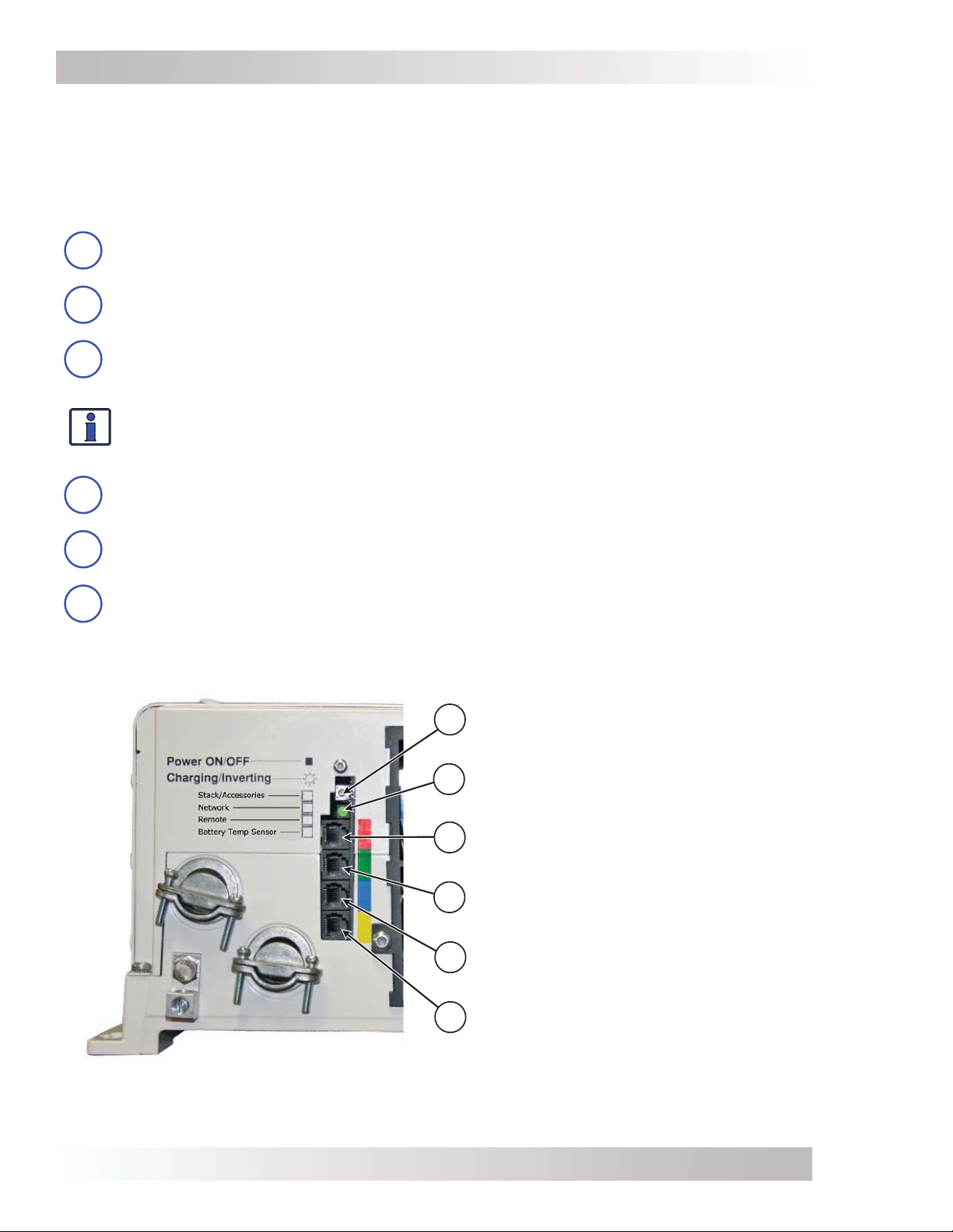
The MS inverter is equipped with the following features (refer to Figures 1-1 and 1-2):
Power ON/OFF Switch – a momentary pushbutton switch that alternately turns the
1
inverter on or off.
Charging/Inverting LED Indicator – this green LED illuminates to provide status
2
information on inverter or charger operation.
Stack/Accessories Connection Port (red label) – a RJ11 port that allows series-
3
stacking, and accepts the optional RSAs (Remote Switch Adapters) for remote on/off
switch operation.
Info: The series-stacking capability—which allows two units to provide 120/240 VAC
output—is only available on MS4024 and MS4048 inverter/chargers. See the ME-SSI
owner’s manual (PN: 64-0009) for additional information on series stacking.
Network Connection Port (green label) – a RJ11 port that accepts optional network
4
capable accessories (i.e., Auto Gen Start or Battery Monitor).
Remote Connection Port (blue label) – a RJ11 port that allows an optional remote
5
control to be connected.
Battery Temperature Sensor Connection Port (yellow label) – a RJ11 port that
6
accepts the remote Battery Temperature Sensor (BTS).
Power ON/OFF Switch
1
Charging/Inverting LED
2
(status)
Stack/Accessories Port
3
(red label – RJ11 connection)
Network Port
4
(green label – RJ11 connection)
Remote Port
5
(blue label – RJ11 connection)
Battery Temp Sensor Port
6
(yellow label – RJ11 connection)
Figure 1-1, Power Switch, Status LED, and Accessory Connection Ports
Page 3
© 2016 Sensata Technologies
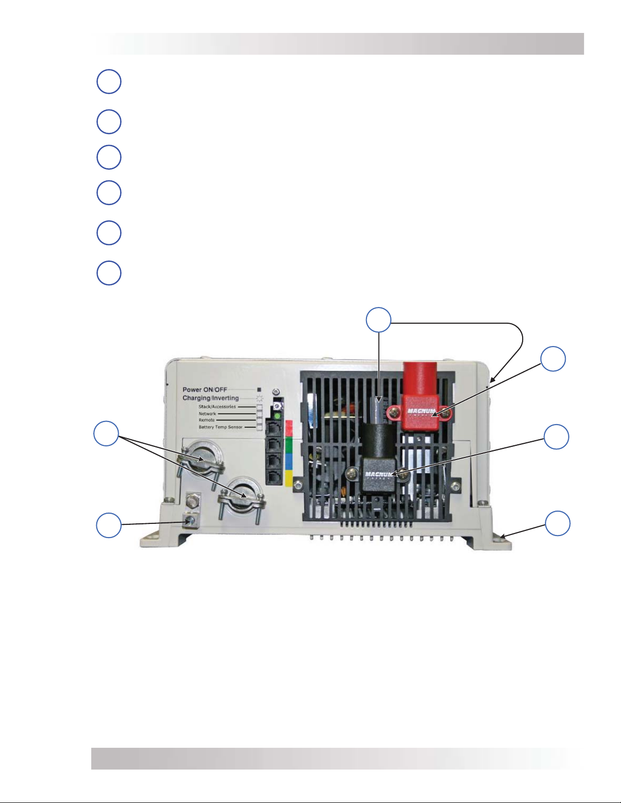
Introduction
DC Equipment Ground Terminal – this connection is used to tie the exposed chassis
7
of the inverter to the DC grounding system. This terminal accepts CU/AL conductors from
#14 to #2 AWG (2.1 to 33.6 mm2). Tightening torque is 45 in-lb.
AC Entry/Exit Connections – two 3/4” knockouts provided with cable-clamp strain
8
reliefs to accommodate and secure the AC input and output fi eld wiring.
Intake Air Vents – ventilation openings to pull in air to help keep the inverter cool for
9
peak performance.
Positive DC Terminal – provides a 360 degree connection point for the positive (+) cable
10
from the battery bank; consists of a 5/16-18 bolt with a Kep or Flange nut that holds the
battery cable to the DC terminal.
Negative DC Terminal – provides a 360 degree connection point for the negative (–)
11
cable from the battery bank; consists of a 5/16-18 bolt with a Kep or Flange nut that
holds the battery cable to the DC terminal.
Mounting Flange – used to secure the inverter to a shelf or wall.
12
AC Entry/
Exit
Connections
8
DC
Equipment
Ground
Terminal
7
Intake Air Vents
(and on right front side)
9
Figure 1-2, Electrical Connection Points
10
Positive (+)
DC Terminal
(under cover)
11
Negative (-)
DC Terminal
(under cover)
12
Mounting
Flange
© 2016 Sensata Technologies
Page 4
Introduction
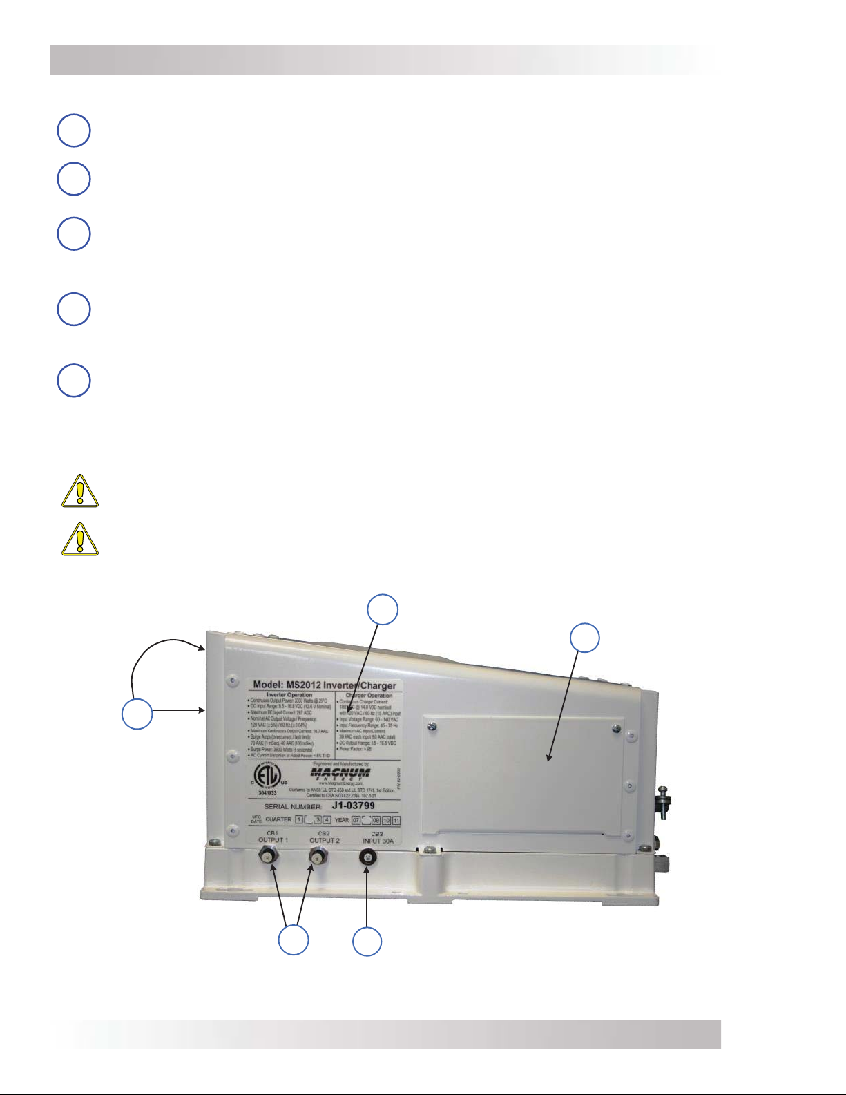
The left side of MS Series inverters are equipped with the following features (Figures 1-3 & 1-4):
Exhaust Air Vents – ventilation openings that allow heated air to be removed by the
13
internal cooling fan.
Model/Serial Number Label – includes model/serial number information, date of
14
manufacture, and inverter and charger specifi cations. See the MS specifi cations in
Appendix A for more information and a list of available models.
AC Access Cover – provides access to the internal AC wiring terminal block
15
(Figure 2-10). This terminal block is used to hardwire all inverter AC input and output
wiring connections. Remove the two screws to access the AC wiring terminal block.
Note: The MS2000 models do not have the AC wiring terminal block.
AC Input Circuit Breaker (CB3) – this circuit breaker protects the unit’s internal
16
charger wiring and pass-thru relay while in Standby mode. The circuit breaker pops out
when it opens—press in to reset. The input circuit breaker is not branch-rated, therefore
branch-rated circuit breakers must be installed in the inverter’s input wiring.
AC Output Circuit Breakers (CB1 & CB2) – these circuit breakers are branch-rated
17
and are only available on models MS2000-15B, MS2000-20B, MS2012-15B, MS201220B, and MS4048-20B. They allow the inverter AC loads to be connected directly to the
inverter’s output without requiring an inverter sub-panel. These circuit breakers pop out
when they open—press in to reset. They can also be manually pulled to disconnect the
inverter’s loads.
CAUTION: Inverter models without the output circuit breakers (CB1 and CB2) must
have branch-rated circuit breakers installed in the inverter’s output wiring.
CAUTION: The inverter’s internal AC transfer relay is rated for 30 amps per leg. The
pass-thru current must be no greater than 30 amps per leg or damage to the relays
may occur.
Model/Serial
Number Label
13
Exhaust
Air Vents
(on back side
and on back
right side)
14
AC Access Cover
15
AC Output Circuit Breakers
(only available on -15B,
-20B output breaker models)
17
AC Input Circuit
16
Breaker
Figure 1-3, Left Side Features (MS2012, MS2812, MS2024, MS4024, MS4048)
Page 5
© 2016 Sensata Technologies
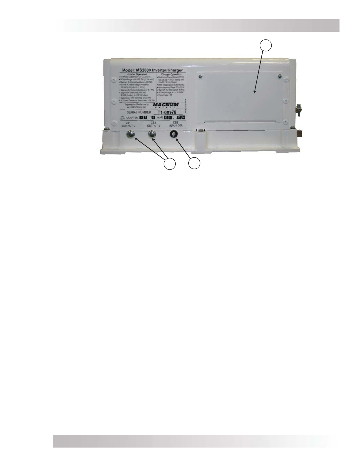
Introduction
15
AC Output Circuit Breakers
17
AC Access Cover
16
AC Input Circuit Breaker
(on -15B, -20B output
breaker models only)
Note: The model shown is not a -15B or -20B model, therefore it does not show any AC output
breakers. Models without output breakers (CB1 & CB2) use carriage bolts to fi ll the breaker openings.
Figure 1-4, Left Side Features (MS2000 Series)
© 2016 Sensata Technologies
Page 6

Installation
2.0 Installation
Info: Installations should be performed by qualifi ed personnel, such as a licensed
or certifi ed electrician. It is the installer’s responsibility to determine which safety
codes apply and to ensure that all applicable installation requirements are followed.
Applicable installation codes vary depending on the specifi c location and application of
the installation.
CAUTION: Review the “Important Product Safety Information” on pages ii-v before any
installation.
CAUTION: The inverter is heavy. Use proper lifting techniques during installation to
prevent personal injury.
The simplifi ed system diagrams shown in Figures 2-1 & 2-2 should be reviewed to assist you in
planning and designing your installation. These drawings are not intended to override or restrict any
national or local electrical codes. The drawings should not be the determining factor as to whether
the installation is compliant, that is the responsibility of the electrician and the on-site inspector.
2.1 Pre-Installation
Before proceeding, read the entire Installation section to determine how best to install your MS
inverter/charger. The more thorough you plan in the beginning, the better your inverter needs
will be met.
2.1.1 Unpacking and Inspection
Carefully remove the MS Series inverter/charger from its shipping container and inspect all contents.
Verify the following items are included:
• The MS Series inverter/charger
• AC access cover with Phillips screws
• Red and black DC terminal covers with Phillips screws
• Two 5/16” Kep or Flange nuts (installed on the DC terminals)
• Battery Temperature Sensor
• Warning label
• MS Series Owner’s Manual
If items appear to be missing or damaged, contact your authorized Magnum product dealer or
Sensata. If at all possible, keep your shipping box to help protect your inverter from damage if it
ever needs to be returned for service. Save your proof-of-purchase as a record of your ownership;
it will also be needed if the unit should require in-warranty service.
Record the unit’s model and serial number in the front of this manual in case you need to provide
this information in the future. It is much easier to record this information now, instead of trying
to gather it after the unit has been installed.
2.1.2 Required Tools and Materials
Hardware/Materials
• Conduit, strain-reliefs and appropriate fi ttings • 1/4” mounting bolts and lock washers
• Electrical tape • Wire ties
Tools
• Miscellaneous screwdrivers • Pliers • Wire strippers
• Drill and drill bits • Pencil or marker • Multimeter
• Level • 1/2” wrench
© 2016 Sensata TechnologiesPage 7

Installation
Utility Power
120/240VAC Output
Main Panel
ON
OFF
OFF
ON
ON
OFF
ON
OFF
ON
OFF
ON
OFF
ON
OFF
ON
OFF
ON
OFF
ON
OFF
ON
OFF
ON
OFF
ON
OFF
120/240VAC
power to
inverter
AC
Transfer
Switch
Generator Power
120/240VAC Output
r
o
t
a
r
e
n
e
G
r
o
t
i
c
a
p
a
C
x
u
l
F
ME-RC50
PWR
FAULT
CHG
INV
ON/OFF
CHARGER
ON/OFF
Remote Controls (Magnum Accessories)
120VAC inverter power
(or 120/240VAC pass-thru power)
to sub-panel
SELECT
AGS METER SETUPSHOREINVERTER
TECH
MS Series
Inverter/
Charger
ME-ARC50
Sub-Panel
OFF
OFF
OFF
OFF
ME-AGS-N
Auto Gen Start
Controller
(Magnum
Accessory)
30A
OFF
ON
OFF
30A
ON
ON
ON
ON
ON
ON
OFF
ON
OFF
ON
OFF
ON
OFF
ME-BMK
Battery Monitor
with shunt
(Magnum
Accessory)
Battery Bank
DC
Shunt
BTS
DC
Overcurrent
Protection
(breaker or
fuse/switch)
120
VAC
240
VAC
ME-SBC
Smart Battery
Combiner
(Magnum
Accessory)
120
VAC
Figure 2-1, Simplifi ed Installation for Permanent Installations (MS Series)
Page 8 © 2016 Sensata Technologies

Installation
Utility Power
120/240VAC Output
Main Panel
ON
AC
Transfer
Switch
Generator Power
120/240VAC Output
Remote Controls (Magnum Accessories)
Power ON/ OFF
Ch ar gi ng/ Inv er t in g
Stack/ Accesso rie s
Net wo rk
Rem ote
Battery Te mp Senso r
ME-RC50
PWR
FAULT
CHG
INV
ON/OFF
CHARGER
ON/
OFF
INVE R T E
AGS METER SETUPSHORE
R
MS2000
Inverter/
Charger
SEL ECT
TECH
Series
ME-AGS-N
Auto Gen
Start
Controller
(Magnum
Accessory)
ME-ARC50
Sub-Panel
OFF
ON
OFF
OFF
ON
ON
OFF
ON
OFF
ON
OFF
ON
OFF
ON
OFF
ON
OFF
ON
OFF
ON
OFF
ON
OFF
ON
OFF
ON
OFF
DC Shunt
120
VAC
DC Overcurrent
120VAC
power to
inverter
(breaker or fuse/switch)
Protection
BTS
ME-BMK
Battery
Monitor with
shunt
(Magnum
Accessory)
ME-SBC
Smart
Battery
Combiner
(Magnum
Accessory)
Battery Bank
Figure 2-2, Simplifi ed Installation for Permanent Installations (MS2000)
© 2016 Sensata TechnologiesPage 9
Installation
2.1.3 Locating the Inverter
Only install the inverter in a location that meets the following requirements:
Clean and Dry – The inverter should not be installed in an area that allows dust, fumes, insects,
or rodents to enter or block the inverter’s ventilation openings. This area also must be free from
any risk of condensation, water, or any other liquid that can enter or fall on the inverter. The
inverter uses stainless steel fasteners, plated copper busbars, a powder-coated aluminum base
and the internal circuit boards are conformal coated—to help fi ght the harmful effects of corrosive
environments. However, the inverter’s life is uncertain if used in these type of environments, and
inverter failure under these conditions is not covered under warranty.
Info: If the inverter is installed in an area where moisture may occur, we recommend
putting silicone dielectric grease compound into the electrical ports (Figure 1-1, Items
3-6). Before installing the cables, or if leaving any ports open, squirt a liberal amount
into each port. Silicone dielectric compound makes an effective moisture and corrosive
barrier to help protect and prevent corrosion to the RJ11 connections.
Cool – The inverter should be protected from direct sun exposure or equipment that produces
extreme heat. The ambient temperature around the inverter must not exceed 77°F (25°C) to
meet power specifi cations.
Ventilation – In order for the inverter to provide full output power and to avoid over-temperature
fault conditions, do not cover or block the inverter’s ventilation openings or install this inverter in
an area with limited airfl ow. The inverter uses two fans to provide forced air cooling, these fans
pull in air through the intake vents (Figure 1-2, Item 9) and blow out air through the exhaust vents
(Figure 1-3, Item 13). Allow at the minimum an airspace clearance of 6” (15.2 cm) at the intake
and exhaust vents, and 3” (7.6 cm) everywhere else to provide adequate ventilation.
If installed in an enclosure, a fresh air intake opening must be provided directly to the front side
(intake vents) of the inverter and an exhaust opening on the back side (exhaust vents) of the
inverter. This allows cool air from the outside to fl ow into the inverter and heated air to exit the
inverter and the enclosure. When mounted in an enclosed compartment, airfl ow must be ≥ 100
cfm in order to maintain no more than a 68°F (20°C) rise in compartment temperature.
CAUTION: Do not mount this inverter in a zero clearance compartment, nor cover or
obstruct the ventilation openings—overheating may result.
Safe – Keep any fl ammable/combustible material (e.g., paper, cloth, plastic, etc.) that may be
ignited by heat, sparks, or fl ames at a minimum distance of 2 feet (61 cm) away from the inverter.
WARNING: The MS Series inverter/charger is not ignition-protected. Do not install this
inverter in any area that contains extremely fl ammable liquids like gasoline or propane.
Close to the battery bank – The inverter should be located as close to the batteries as possible.
Long DC wires tend to lose effi ciency and reduce the overall performance of an inverter. However,
the unit should not be installed in the same compartment as the batteries or mounted where it
will be exposed to gases produced by the batteries. These gases are corrosive and will damage
the inverter; also, if these gases are not ventilated and allowed to collect, they could ignite and
cause an explosion.
Accessible – Do not block access to the inverter’s remote control and accessory ports, as well as
the inverter’s controls and status indicator. Allow enough room to access the AC and DC wiring
terminals and connections, as they will need to be checked and tightened periodically. See Figures
2-3 and 2-4 for the MS Series inverter/charger’s dimensions.
Away from sensitive electronic equipment – High powered inverters can generate levels of RFI
(Radio Frequency Interference). Locate any electronic equipment susceptible to radio frequency
and electromagnetic interference as far away from the inverter as possible.
Page 10 © 2016 Sensata Technologies
Installation
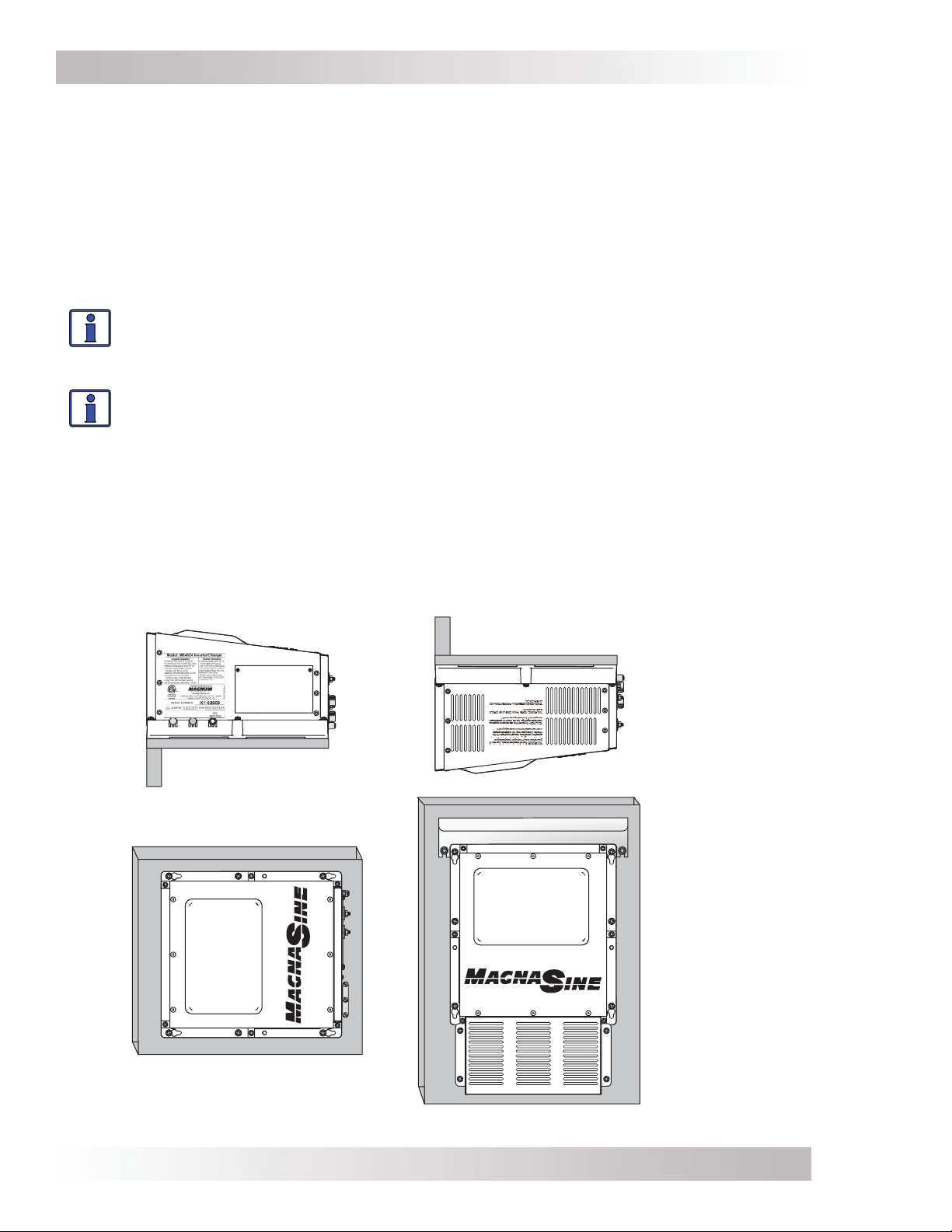
2.2 Mounting the Inverter
The inverter base can reach a temperature up to 90°C (194°F) and should be mounted on a
noncombustible surface*. This surface and the mounting hardware must also be capable of
supporting at least twice the weight of the inverter. To meet regulatory requirements, the MS
Series must be mounted in one of the following positions as shown in Figure 2-3:
• above or under a horizontal surface (shelf or table),
• on a vertical surface (wall) with the DC terminals to the right,
• on a vertical surface (wall) with the DC terminals toward the bottom, the MP-HOOD (inverter
hood) installed on the top, and either the ME-CB (Conduit box), MMP series (single inverter
enclosure), or MP Series (multiple inverter enclosure) installed on the inverter’s bottom.
Info: The ME-CB, MMP and MP Series enclosures prevent material from falling out the
bottom in the event of an internal fi re, and also allow suffi cient ventilation to prevent the
inverter from overheating under normal operating conditions. The MP-HOOD inverter
hood helps prevent items from falling inside causing damage to the inverter.
Info: Sensata provides backplates for mounting the inverter(s). These backplates also
provide the ability to mount either the MMP Series enclosure (PN: BP-MMP) or the MP
Series enclosure (PN: BP-S single plate, or BP-D dual plate).
After determining the mounting position, refer to the physical dimensions as shown in Figures
2-4 or 2-5, or use the base of the inverter as a template to mark your mounting screw locations.
After marking the mounting screw locations, mount the unit with appropriate mounting hardware.
* Noncombustible surface – A surface made of material that will not ignite, burn, support combustion,
or release fl ammable vapors when subjected to fi re or heat as per the ASTM E136 standard. For the
most part, these are materials that are largely comprised of inorganic materials such as stone, steel,
iron, brick, tile, concrete, slate, and glass. Avoid common building materials such as gypsum board as
well as any paint, wall coverings, and all types of wood.
30
30
SHELF OR TABLE
MOUNTED
(RIGHT SIDE UP)
WALL MOUNTED
(DC TERMINALS TO THE RIGHT)
SHELF OR TABLE MOUNTED
(UP SIDE DOWN)
WALL MOUNTED
(DC TERMINALS
DOWN*)
FACING
*WHEN THE INVERTER
IS MOUNTED IN THIS
POSITION, THE MP-HOOD
(
INVERTER HOOD ON TOP),
AND THE ME-CB (CONDUIT
BOX ON BOTTOM) OR MP/
MMP S
ERIES ENCLOSURES
MUST BE USED.
Figure 2-3, Approved Mounting Positions
© 2016 Sensata TechnologiesPage 11
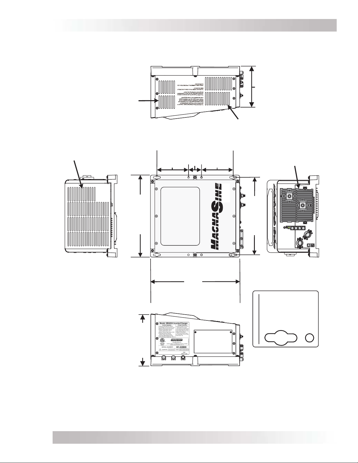
Installation
Side
Right
6 ⅝"
(16.8 cm)
Exhaust Air Vents
Vents
Exhaust Air Vents
4 ⅞"
2"
4 ⅞"
(12.4 cm)
(5.1 cm)
(12.4 cm)
Air Intake
Air Intake Vents
Top
12 ⅝"
8"
12"
(32.1 cm)
Front
(30.5 cm)
Bottom
13 ¾"
(34.9 cm)
9/32"
Keyhole
slots (x4)
Mounting Holes
(20.3 cm)
30
30
Left
Side
(7 mm)
Use up to
screw/bolt
Mounting
Holes (x4)
Figure 2-4, MS Dimensions (MS2012, MS2812, MS2024, MS4024, MS4048)
Page 12© 2016 Sensata Technologies
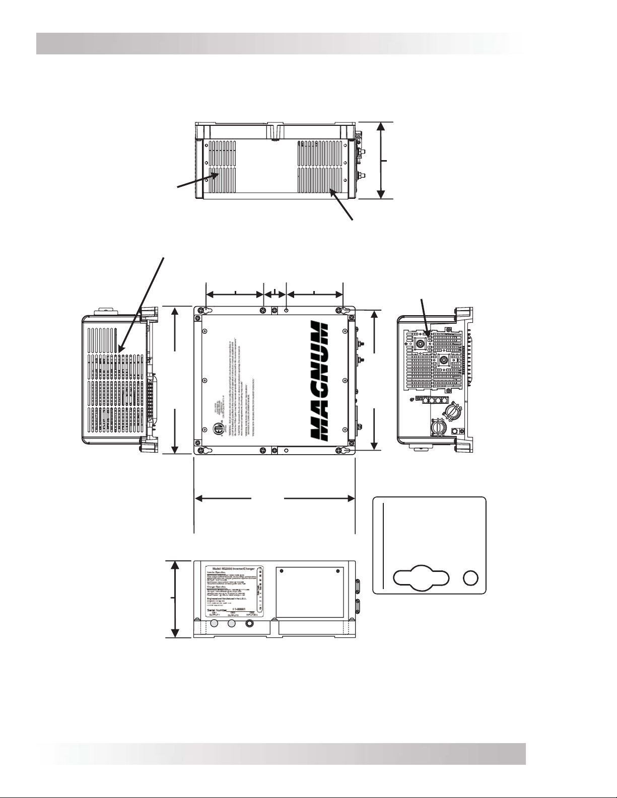
Installation
Side
Right
6 ⅝"
(16.8 cm)
Top
Exhaust Air Vents
4 ⅞"
12 ⅝"
(32.1 cm)
2"
4 ⅞"
(12.4 cm)
(5.1 cm)
(12.4 cm)
Vents
Air Intake
Air Intake Vents
12"
Front
(30.5 cm)
Bottom
13 ¾"
(34.9 cm)
9/32"
Keyhole
slots (x4)
(7 mm)
Use up to
screw/bolt
Mounting
Holes (x4)
6 ⅝"
(16.8 cm)
30
Left
Side
Figure 2-5, MS Dimensions (MS2000)
© 2016 Sensata TechnologiesPage 13
Mounting Holes

Installation
2.3 Wiring the Inverter – General Requirements
This section describes the requirements and recommendations for wiring the MS Series inverter/
charger. Before wiring the MS Series inverter/charger, carefully read all instructions.
Wiring should meet all local codes and standards and be performed by qualifi ed personnel
such as a licensed electrician.
The NEC (National Electric Code, ANSI/NFPA 70) for the United States and the CEC (Canadian
Electrical Code) for Canada provide the standards for safe wiring. The NEC/CEC lists requirements
for wire sizes, overcurrent protection, and installation methods/standards.
Inverter/charger systems involve power from multiple sources (inverter, generator, utility, batteries,
solar arrays, etc.) which make the wiring more hazardous and challenging.
The input and output AC and DC circuits are isolated from the inverter chassis. The inverter system
grounding is the responsibility of the installer in accordance with the NEC/CEC and local codes.
WARNING: Ensure all sources of DC power (i.e., batteries, solar, wind, or hydro) and
AC power (utility power or AC generator) are de-energized (i.e., breakers opened, fuses
removed) before proceeding—to prevent accidental shock.
2.3.1 Protecting Wire – Conduit Box
The AC and DC wires to and from the inverter must be protected as required by code. This can be
done by using jacketed wires or by feeding the wires through conduit. Sensata offers DC conduit
boxes (ME-CB), a single inverter enclosure (MMP Series), and a multiple inverter enclosure (MP
Series) that include the necessary AC and DC inverter breakers that allow both the AC and DC
conduit to be connected to the inverter.
Info: Remove strain reliefs and replace with 3/4” grommets if using a conduit box or
MMP/MP enclosure, and the AC wires are individual conductors (i.e., not jacketed).
2.3.2 Wiring Requirements
• All conductors must be protected by conduit, tape, or placed in a raceway.
• The conductor insulation must be of a type that is approved for the voltage, operating
temperature, and location of use.
• Always check for existing electrical, plumbing, or other areas of potential damage prior to
making cuts in structural surfaces or walls.
• Do not mix AC and DC wiring in the same conduit or panel unless specifi cally approved/
designed for both AC and DC wiring. Where DC wiring must cross AC or vice-versa, try to
make the wires at the crossing point perpendicular (90 degrees) to one another.
• Both AC and DC overcurrent protection must be provided as part of the installation.
• The inverter requires a reliable negative and ground return path directly to the battery.
• Use only copper wires with a minimum temperature rating of 90°C (194°F).
2.3.3 Wire Routing
Before connecting any wires, determine all wire routes to and from the inverter. Conductors
passing through walls, bulkheads, etc., must be protected to minimize insulation damage, such
as chafi ng. Typical routing scenarios are:
• AC input wiring from the main AC panel to the inverter
• AC input wiring from a generator (optional) to the inverter
• DC input wiring from the batteries to the inverter
• AC output wiring from the inverter to the AC sub-panel or to dedicated circuits
• Battery Temperature Sensor cable from the inverter to the batteries
• Remote control cable (optional) to the inverter
• AC and DC ground wiring to and from the inverter
2.3.4 Torque Requirements
Torque all AC wiring connections to 16 in-lbf (1.8 N-m). Torque DC cable connections from 10 to
12 ft lbf (13.6 to 16.3 N-m).
Page 14 © 2016 Sensata Technologies

Installation
2.4 DC Wiring
This section describes the inverter’s required DC wire sizes, the recommended disconnect/
overcurrent protection, and how to make the DC connections to the inverter and the battery bank.
Refer to Figure 2-6 when connecting the DC wires.
WARNING: Even though DC voltage is “low voltage”, signifi cant hazards may be
present, particularly from short circuits of the battery system.
CAUTION: The inverter is NOT reverse polarity protected—which means that if the
negative and positive battery voltage is connected backwards to the inverter, the
inverter will likely be damaged. You should verify the correct voltage polarity using a
voltmeter BEFORE connecting the DC wires. Color code the the DC cables/wires with
colored tape or heat shrink tubing: RED for positive (+), WHITE for negative (–), and
GREEN (or bare copper) for DC ground, to avoid polarity problems.
CAUTION: To remove battery power from the inverter, disconnect the battery positive
connection before the negative connection. This requirement can prevent damage to the
inverter and/or an accessory connected to the inverter.
Note: When an accessory that is not powered by the inverter (e.g., ME-AGS-N and ME-BMK)
is installed and connected to the inverter (via a network communication cable), the battery
negative connection of the inverter and each accessory must be at the same potential
(i.e., electrically common with each other) until the positive connection of each device is
removed. This prevents a high impedance path developing between the connected devices
(i.e., inverter and accessories), which can cause the network cable to become the DC return
path to the battery—possibly resulting in permanent damage to all connected devices on the
network. This can be prevented if the battery negative connection of each device is always
connected before connecting/disconnecting any battery positive.
CAUTION: Before wiring the DC cables, review the safety information at the beginning
of this manual and the information below to ensure a safe and long-lived system.
• When the inverter is installed in a photovoltaic system, the NEC requires that the DC circuit
conductors and overcurrent devices to the inverter be sized to carry not less than 125% of
the inverter’s maximum current rating.
• The DC positive and negative cables connected to the inverter from the battery bank should
be tied together with wire ties or electrical tape approximately every 6 inches (15.2 cm). This
helps improve the surge capability and reduces the effects of inductance, which improves the
inverter waveform and reduces the wear of the inverter’s fi lter capacitors.
• Crimped and sealed copper ring terminal lugs with a 5/16” hole should be used to connect the
DC wires to the inverter’s DC terminals.
• The battery bank voltage MUST match the DC voltage required by the inverter (i.e., 24-volt
battery bank for a 24-volt inverter) or the inverter may be damaged.
• To ensure the maximum performance from the inverter, all connections from the battery bank
to the inverter should be minimized. The exception is the DC overcurrent disconnect in the
positive line and a shunt in the negative line. Any other additional connection will contribute
to additional voltage drops, and these extra connection points may loosen during use.
• All wiring to the battery terminals should be checked periodically (once a month) for proper
tightness. The torque requirement for the DC terminals is between 10 to 12 ft lbf (13.6 to
16.3 N-m). If you don’t have a torque wrench, ensure all DC terminals are tight and cannot
move. Be aware that overtightening or misthreading the nuts on the DC terminals can cause
the bolts to strip and snap/break off.
• A brief spark or arc may occur when connecting the battery cables to the inverter DC terminals;
this is normal and due to the inverter’s internal capacitors being charged.
© 2016 Sensata TechnologiesPage 15
 Loading...