

Magnum MMG75D, MMG100D Operating Manual
Parts manuals available online! www.m-p-llc.com
POWER PRODUCTS LLC
DIESEL GENERATOR
75
MMG75D • MMG100D
OPERATING MANUAL

INTRODUCTION
This manual provides information and procedures to safely operate and maintain the engine and generator. For your
own safety and protection from physical injury, carefully read, understand, and observe the safety instructions
described in this manual. The information contai ned in this manual was based on machines in production at the time
of publication. Magnum Power Products LLC reserves the right to change any portion of this information without notice.
DO NOT MODIFY or use this equipment for any application other than which it was designed for.
Magnum Power Products LLC recommends that a trained and licensed professional perform all electrical wiring and
testing functions. Any wiring should be in compliance with the United States National Electric Code (NEC), state and
local codes and Occupational Safety and Health Association (OSHA) guidelines.
Keep a copy of this manual with the unit at all times. Additional copies are available from Magnum Power Products
LLC, or can be found at www.m-p-llc.com. An engine operator’s manual is supplied with the unit at the time of
shipment from the factory. The manual provides detailed operation and maintenance procedures for the engine.
Additional copies of the engine operators manual are available from the engine manufacturer.
MAGNUM POWER PRODUCTS LLC
215 Power Drive • Berlin, WI 54923
U.S.A.
Phone: 920-361-4442
FAX: 920-361-4416
Toll Free: 1-800-926-9768
www.m-p-llc.com
For technical or parts QUESTIONS, please contact the Magnum Power Products LLC Customer
Support or Technical Support team at 1-800-926-9768. Please have your serial number available.
Visit www.m-p-llc .com to download or print the current parts manual(s) for all your Magnum Power
Products LLC equipment and online parts ordering options. Par ts manuals can also be purchased
by calling your local Magnum Power Products LLC distributor.
To ORDER SERVICE PARTS, please contact the de aler from which you purchased the unit, or call
Magnum Power Products LLC to locate a dealer in your area.
Engine Make:__________________________________________
Engine Serial Number:___________________________________
Engine Model Number: __________________________________
Generator Make: _______________________________________
Generator Model Number: ________________________________
Generator Serial Number: ________________________________
Unit Model Number:_____________________________________
Unit Serial Number: _____________________________________
CALIFORNIA PROPOSITION 65 WARNING: Diesel engine exhaust and some of its
constituents are known to the state of California to cause cancer, birth defects and
2
WARNING
other reproductive harm.

TABLE OF CONTENTS
INTRODUCTION ............................................................................................................................... 2
SAFETY NOTES ............................................................................................................................... 6
OPERATING SAFETY ...................................................................................................................... 6
ENGINE SAFETY .............................................................................................................................. 7
ELECTRICAL SAFETY ..................................................................................................................... 7
TOWING SAFETY ............................................................................................................................. 8
REPORTING TRAILER SAFETY DEFECTS .................................................................................... 9
SAFETY SYMBOL SUMMARY ....................................................................................................... 10
SPECIFICATIONS - MMG75D ........................................................................................................11
SPECIFICATIONS - MMG100D ...................................................................................................... 12
UNIT DIMENSIONS ........................................................................................................................ 13
UNIT SERIAL NUMBER LOCATIONS ............................................................................................ 14
COMPONENT LOCATIONS ........................................................................................................... 15
MAIN CONTROL PANEL FEATURES, STANDARD ...................................................................... 16
MAGNUM DIGITAL CONTROLLER (MDC) .................................................................................... 18
DIGITAL CONTROLLER FEATURES AND FUNCTIONS .............................................................. 18
GENERATOR MONITORING ......................................................................................................... 19
ENGINE MONITORING .................................................................................................................. 19
DIESEL EXHAUST FILTER MONITORING .................................................................................... 21
WET STACKING ............................................................................................................................. 22
FINE VOLTAGE ADJUSTMENT ..................................................................................................... 22
FRONT HOOD OPERATION .......................................................................................................... 23
PRE-START CHECK LIST .............................................................................................................. 24
MANUAL STARTING OF THE GENERATOR ................................................................................ 25
“AUTO” (REMOTE) STARTING OF THE GENERATOR ................................................................ 27
SHUTTING DOWN THE GENERATOR .......................................................................................... 27
EXHAUST FILTER CLEANING OPERATIONS .............................................................................. 28
MDC CONTROLLER INFORMATION DISPLAYS, FUNCTIONS, AND RESET ............................ 29
MAGNUM DIGITAL CONTROLLER (MDC) - GENERATOR OPERATIONAL STATUS ................ 29
MAGNUM DIGITAL CONTROLLER (MDC) - ALARM MANAGEMENT .......................................... 29
MAGNUM DIGITAL CONTROLLER (MDC) - LIST OF ALARMS ................................................... 30
JOHN DEERE ECU INFORMATION DISPLAYS AND FUNCTIONS ............................................. 31
MDC CONTROLLER – HISTORY ................................................................................................... 32
ADJUSTING THE DISPLAY BACKLIGHTING ................................................................................ 33
RESETTING THE “TIME TO SERVICE” REMINDER ..................................................................... 33
TROUBLESHOOTING AUTOMATIC SHUTDOWN CONDITIONS ................................................ 33
GENERATOR OUTPUT CONNECTION LUGS .............................................................................. 35
VOLTAGE SELECTOR SWITCH .................................................................................................... 36
4-POSITION VOLTAGE SELECTOR SWITCH OPTION ................................................................ 37
EMERGENCY STOP SWITCH ....................................................................................................... 38
MAIN CIRCUIT BREAKER .............................................................................................................. 38
VOLTAGE REGULATION ............................................................................................................... 38
CUSTOMER CONVENIENCE OUTLETS ....................................................................................... 39
DERATING FOR ALTITUDE ........................................................................................................... 39
REMOTE START TERMINAL BLOCK ............................................................................................ 39
TRANSFER SWITCH ...................................................................................................................... 40
BELT TENSION ............................................................................................................................... 41
AUTO EXERCISE TIMER ............................................................................................................... 41
ENGINE AND GENERATOR MAINTENANCE ............................................................................... 41
DAILY WALK AROUND INSPECTION ........................................................................................... 42
BASIC MAINTENANCE SCHEDULE - JOHN DEERE ENGINE ..................................................... 42
ENGINE BREAK-IN REQUIREMENTS ........................................................................................... 43
EXHAUST FILTER SERVICE REQUIREMENTS ........................................................................... 43
LIFTING THE GENERATOR ........................................................................................................... 44
TOWING THE TRAILER ................................................................................................................. 44
TRAILER WHEEL BEARINGS ........................................................................................................ 44
CHECKING GENERATOR DRIVE PLATE TORQUE ..................................................................... 45
AUXILIARY FUEL TANK OPTION .................................................................................................. 45
Page
3

FUEL TRANSFER PUMP OPTION ................................................................................................. 45
VISCOUS FAN CLUTCH OPTION .................................................................................................. 46
AC WIRING DIAGRAM - 3 POSITION VOLTAGE SELECTOR SWITCH ...................................... 47
AC WIRING DIAGRAM - 4 POSITION VOLTAGE SELECTOR SWITCH OPTION ........................ 48
AC WIRING DIAGRAMS FOR OPTIONAL EQUIPMENT ............................................................... 49
DC WIRING DIAGRAM ................................................................................................................... 50
DC WIRING DIAGRAMS FOR OPTIONAL EQUIPMENT ............................................................... 51
WIRING BLOCK DIAGRAM - DEDICATED 12 LEAD GENERATORS OPTION ............................ 52
TRAILER WIRING DIAGRAM .........................................................................................................53
WIRING HARNESS - ELECTRIC BRAKE OPTION ........................................................................ 54
SERVICE LOG ................................................................................................................................ 55
4

This Page Intentionally Left Blank
5
SAFETY NOTES
DANGER
CAUTION
This is the safety alert symbol. It is used to alert you to potential personal injury hazards. Obey all
safety messages that follow this symbol to avoid possible injury or death.
This manual contains DANGERS, WARNINGS, CAUTIONS, NOTICES and NOTES which must be
followed to prevent the possibility of improper service, damage to the equipment, personal injury or death.
The following formatting options will apply when calling the reader’s attention to the DANGERS,
WARNINGS, CAUTIONS, NOTICES and NOTES.
INDICA TES A HAZARDOUS SITUATION WHICH, IF NOT AVOIDED, WILL RESULT IN
Indicates a hazardous situation which, if not avoided, could result in death or serious
Indicates a hazardous situation which, if not avoided, may result in minor or moderate injury.
Indicates a hazardous situation which, if not avoided, may result in property or equipment
DEATH OR SERIOUS INJURY.
WARNING
injury.
damage.
Note: Notes contain additional information important to a procedure and will be found within the regular text body
of this manual.
OPERATING SAFETY
Before using the generator, be sure you read and understand all of the instructions! This equipment was
designed for specific applications; DO NOT modify or use this equipment for any application other than
which it was designed for. Equipment operated improperly or by untrained personnel can be dangerous!
Read the operating instructions and familiarize yourself with the location and proper use of all instruments
and controls. Inexperienced operators should receive instruction from someone familiar with the equipment
before being allowed to operate or set up the generator. The following points should be practiced at all times:
• The area immediately surrounding the generator should be dry, clean, and free of debris.
• NEVER start a unit in need of repair.
• Make certain the generator is securely fastened to a good earthen ground before use.
• NEVER operate the unit on a combustible surface.
• NEVER operate the generator if any of the following conditions exist during operation:
1. Noticeable change in engine speed.
2. Loss of electrical output.
3. Equipment connected to the generator overheats.
4. Sparking occurs.
5. Engine misfires or there is excessive engine/generator vibration.
6. Protective covers are loose or missing.
7. If the ambient air temperature is above 120°F (49°C).
• Make sure slings, chains, hooks, ramps, jacks, and other types of lifting devices are attached securely
and have enough weight-bearing capacity to lift or hold the equipment safely. Always remain aware
of the position of other people around you when lifting the equipment.
• NEVER operate unit while tired, distracted, or under the influence of drugs or alcohol.
6

ENGINE SAFETY
Internal combustion engines present special hazards during operation and fueling! Failure to follow the
safety guidelines described below could result in severe injury or death. Read and follow all safety warnings
described in the engine operator's manual. A copy of this manual was supplied with unit when it was
shipped from the factory.
• DO NOT run engine indoors or in an area with poor ventilation. Diesel engine exhaust contains carbon
monoxide, a deadly, odorless and colorless gas which, if inhaled, can cause nausea, fainting or death.
Only use this unit outside and away from windows, doors, and ventilation equipment.
• DO NOT fill fuel tank near an open flame, while smoking, or while engine is running. DO NOT fill tank
in an enclosed area with poor ventilation.
• DO NOT operate with the fuel tank cap loose or missing.
• DO NOT touch or lean against hot exhaust pipes or engine cylinders.
• DO NOT clean air filter with gasoline or other types of low flash point solvents.
• DO NOT remove engine coolant cap while engine is hot.
• DO NOT operate the unit without a functional exhaust system. Prolonged exposure to sound levels
in excess of 85 dB(A) can cause permanent hearing loss. Wear hearing protection when working
around a running engine.
• Keep hands, feet and loose clothing away from moving parts on the generator and engine.
• Keep area around exhaust pipes and air ducts free of debris to reduce the chance of an accidental fire.
• Batteries contain sulfuric acid which can cause severe injury or death. Sulfuric acid can cause eye
damage, burn flesh or eat holes in clothing. Protective eye wear and clothing are necessary when
working on or around the battery. Always disconnect the NEGATIVE (-) battery cable from the
corresponding terminal before performing any service on the engine or other components.
ELECTRICAL SAFETY
The unit is powered by a generator driven by a diesel engine. While the engine is running, potentially
lethal voltages are present at the 120V Ground Fault Circuit Interrupt (GFCI) outlets and the 240V twist
lock outlets located on the control panel, and at the connection lugs and optional cam lock receptacles.
Failure to follow the safety guidelines described below could result in severe injury or death.
• Only a qualified and licensed electrician should make connections to the generator.
• NEVER wash the unit with high pressure hoses or power washers.
• NEVER start the unit under load. The circuit breakers must be in the “OFF” position when starting the
unit in MANUAL mode. The circuit breakers can be in the “ON” position only when started in the AUTO
mode. A transfer switch must be used in the AUTO mode to deflect the load upon start up.
• ALWAYS disconnect the NEGATIVE (-) battery cable from the corresponding terminal before
performing any service on the engine, generator, or any other components. Remove the NEGATIVE
(-) battery cable from the corresponding terminal if the unit is to be stored or transported.
• ALWAYS use extreme caution when servicing this unit in damp conditions. Do not service the unit if
your skin or clothing is wet. Do not allow water to collect around the base of the unit.
• ALWAYS connect the unit to a good earthen ground before use. Follow all local, state or United States
National Electric Code (NEC) guidelines.
7

TOWING SAFETY
Towing a trailer requires care! Both the trailer and vehicle must be in good condition and securely fastened
to each other to reduce the possibility of an accident. Also, some states require that large trailers be
registered and licensed. Contact your local Department of Transportation office to check on license
requirements for your particular unit.
• Check that the hitch and coupling on the towing vehicle are rated equal to, or greater than, the trailer's
Gross Vehicle Weight Rating (GVWR).
• Check tires on trailer for tread wear, inflation, and condition.
• NEVER tow trailer using defective parts! Inspect the hitch and coupling for wear or damage.
• Make sure the trailer hitch and the coupling are compatible. Make sure the coupling is securely fastened
to the vehicle.
• Connect safety chains in a crossing pattern under the tongue and ATTACH THE BREAKAWAY
CABLE TO THE REAR BUMPER OF THE TOWING VEHICLE. Do not attach the cable to the trailer
hitch.
• Make sure directional and brake lights on the trailer are connected and working properly.
• Check that lug nuts holding wheels are tight and that none are missing.
• Maximum recommended speed for highway towing is 45 mph (72 km/h). Recommended off-road
towing speed is not to exceed 10 mph (16 km/h) or less, depending on terrain.
Before towing the trailer, check that the weight of the trailer is equal across all tires. On trailers with
adjustable height hitches, adjust the angle of the trailer tongue to keep the trailer as level as possible. On
units equipped with a tandem axle trailer, a large angle between the trailer and tow vehicle will cause more
weight to be carried by one axle, which could cause premature wear on the tires and axles and cause
potentially unsafe operating conditions.
The trailer is equipped with hydraulic surge brakes or electric surge brakes. Check the operation of the
brakes by braking the vehicle at a slow speed before entering traffic. Both the trailer and the vehicle should
brake smoothly. If the trailer seems to be pushing, check the level in the surge brake fluid reservoir.
When towing, maintain extra space between vehicles and avoid soft shoulders, curbs and sudden lane
changes. If you have not pulled a trailer before, practice turning, stopping, and backing up in an area away
from heavy traffic.
A film of grease on the coupler will extend coupler life and eliminate squeaking. Wipe the coupler clean
and apply fresh grease each time the trailer is towed.
8

REPORTING TRAILER SAFETY DEFECTS
If you believe your trailer has a defect which could cause a crash or could cause injury or death, you should immediately
inform the National Highway Traffic Safety Administration (NHTSA) in addition to notifying Magnum Power Products
LLC.
If NHTSA receives similar complaints, it may open an investigation; and if it finds that a safety defect exists in a group
of vehicles, it may order a recall and remedy campaign. However, NHTSA cannot become involved in an individual
problem between you, your dealer, or Magnum Power Products LLC.
To contact NHTSA, you may either call the Auto Safety Hotline toll-free at 1-888-327-4236 (TTY:1-800-424-9153),
go to http://www.safercar.gov; or write to:
Administrator
NHTSA
1200 New Jersey Avenue S.E.
Washington, DC 20590
You can also obtain other information about motor vehicle safety from http://www.safercar.gov.
9
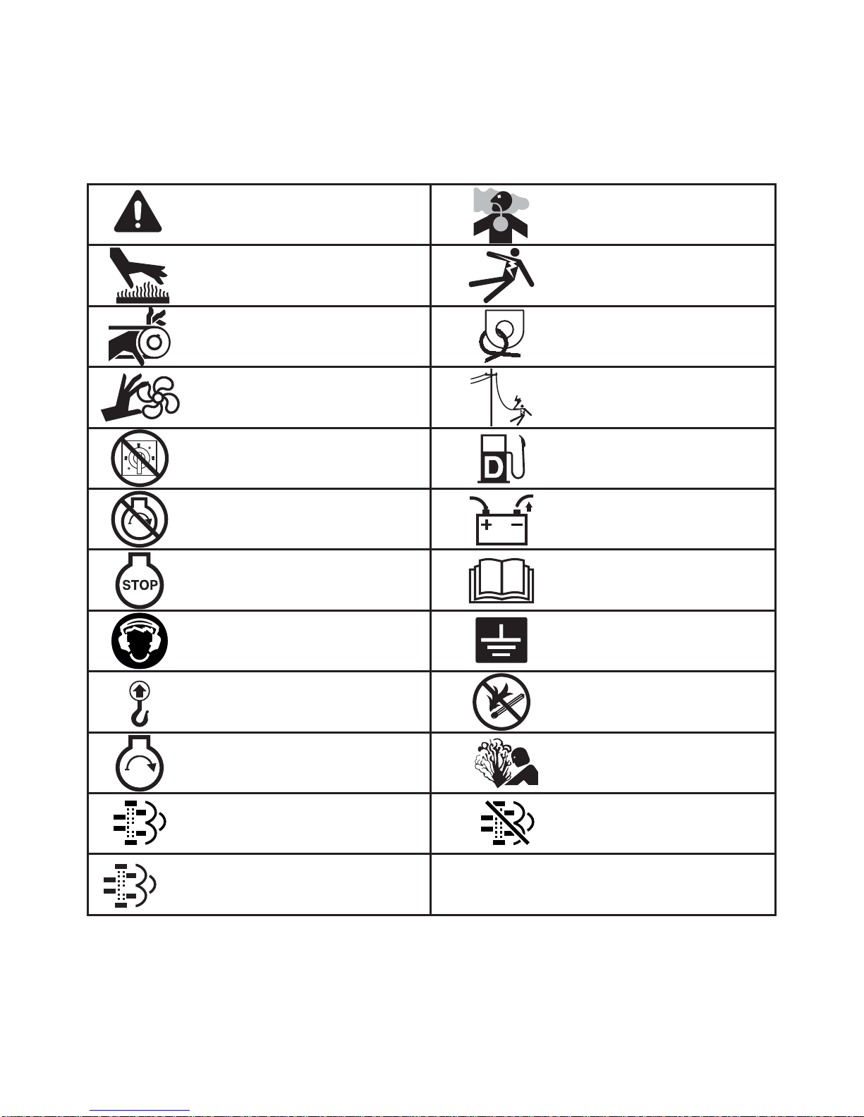
SAFETY SYMBOL SUMMARY
Dangerous voltage may be
present.
Hot surface(s) nearby.
Anchor/tie down point.
Belt/entanglement hazard; keep
body parts clear of this area.
Fan hazard; keep body parts
clear of this area.
Isolate generator to prevent
electrocution hazard.
Use clean diesel fuel only.
Never change switch position
while engine is running.
Remove negative battery
cable before performing
any service on unit.
Stop engine before making
connections.
Fire/explosion hazard; keep
open flames away from unit.
Lift here only.
Asphyxiation hazard; operate
in well ventilated area.
Safety alert symbol; used to
alert you to potential personal
injury hazards.
Read and understand the
supplied operator’s manual
before operating unit.
Stop engine before fueling.
Unit electrical ground.
Hearing protection required
while operating unit with doors
open.
Burn/scald hazard;
pressurized steam.
Engine running.
Auto Exhaust Filter Cleaning
enabled.
Manual/Service Regeneration
activation.
Auto Exhaust Filter Cleaning
disabled.
M
This equipment has been supplied with numerous safety and operating decals. These decals provide important
operating instructions and warn of dangers and hazards. Replace any missing or hard-to-read decals and use care
when washing or cleaning the unit. Decal placement and part numbers can be found in the parts manual. Below is
a summary of the intended meanings for the symbols used on the decals.
10

SPECIFICATIONS - MMG75D
Read this manual carefully before attempting to use this generator. The potential for property damage, personal
injury or death exists if this equipment is misused or installed incorrectly. Read all of the manuals included with this
unit. Each manual details specific information regarding items such as set up, use and service requirements.
SPECIFICATIONS ARE SUBJECT TO CHANGE WITHOUT NOTICE.
MAGNUM MODEL MMG75D MMG75D Super Start
Engine
Make/Brand...................................................................... John Deere ...................................John Deere
Model ............................................................................... PE4045HFG92..............................PE4045HFG92
Horsepower - prime hp (kW) .......................................... 97 (72)...........................................97 (72)
Horsepower - standby hp (kW) ....................................... 107 (80).........................................107(80)
Operating Speed rpm .....................................................1800 ..............................................1800
Displacement in
Cylinders - qty .................................................................. 4 ....................................................4
Fuel Consumption - 100% prime gph (Lph) ................... 4.78 (18.1).....................................4.78 (18.1)
Battery Type..................................................................... Group 24 .......................................Group 24
Battery Voltage (Quantity per Unit) ..................................12V (1) ..........................................12V (1)
Battery Rating .................................................................. 720 CCA .......................................720 CCA
Generator
Make/Brand...................................................................... Marathon Electric ..........................Marathon Electric
Model ............................................................................... 361PSL1602 (1647)......................363PSL1607 (1661)
Type, Insulation................................................................ Brushless, H..................................Brushless, H
Generator Set (Engine/Generator)
3Ø - Standby kW (kVA) ................................................... 69 (86)...........................................70 (88)
Amps - 3Ø Standby 480V (208V) A ................................ 103 (239).......................................106 (244)
3Ø - Prime kW (kVA) ...................................................... 62 (77)...........................................63 (79)
Amps - 3Ø Prime 480V (208V) A .................................... 93 (214).........................................95 (219)
1Ø - Standby kW (kVA) ................................................... 60 (60)...........................................66 (66)
Amps - 1Ø Standby - 240V A .......................................... 250 ................................................275
1Ø - Prime kW (kVA) ...................................................... 56 (56)...........................................60 (60)
Amps - 1Ø Prime - 240V A ............................................. 233 ................................................250
Frequency Hz .................................................................. 60 ..................................................60
Power Factor.................................................................... 1 (1Ø), 0.8 (3Ø).............................1 (1Ø), 0.8 (3Ø)
3
(L) .......................................................274 (4.5)........................................274 (4.5)
Weights
Dry Weight, Skid Mounted lbs (kg) .................................3530 (1600)...................................3860 (1750)
Operating Weight, Skid Mounted lbs (kg) ...................... 4700 (2131)...................................5040 (2286)
Dry Weight, Trailer Mounted* lbs (kg) ............................ 4240 (1923)...................................4570 (2073)
Operating Weight, Trailer Mounted* lbs (kg) .................. 5410 (2454)...................................5750 (2608)
*Standard trailer only. Consult factory for custom trailer weights.
Capacities
Fuel Tank Volume gal (L) ................................................ 165 (625).......................................165 (625)
Usable Fuel Volume gal (L) ............................................ 151 (572).......................................151 (572)
Coolant (incl. engine) qt (L) ............................................ 22.0 (20.8).....................................22.0 (20.8)
Oil (incl. filter) qt (L) ........................................................ 15.5 (14.7).....................................15.5 (14.7)
Maximum Run Time hrs .................................................31 ..................................................31
AC Distribution
Circuit Breaker Size ......................................................... 300 ................................................300
Voltage Selection .............................................................3 Position Switch (lockable) ..........3 Position Switch (lockable)
Voltage Regulation........................................................... +/- 1% ...........................................+/- 1%
Voltages Available 1Ø...................................................... 120, 139, 208, 220, 240, 277 ........120, 139, 208, 220, 240, 277
Voltages Available 3Ø...................................................... 208, 220, 440, 480 ........................208, 220, 440, 480
Trailer
Number of Axles .............................................................. 1 ....................................................1
Capacity - Axle Rating lbs (kg) ....................................... 6000 (2722)...................................6000 (2722)
Tire Size in ......................................................................15 ..................................................15
Brakes.............................................................................. Surge ............................................Surge
Hitch - Standard ............................................................... 3" Ring .........................................
Maximum Tire Pressure psi ............................................ 65 ..................................................65
.3" Ring
11

SPECIFICATIONS - MMG100D
Read this manual carefully before attempting to use this generator. The potential for property damage, personal
injury or death exists if this equipment is misused or installed incorrectly. Read all of the manuals included with this
unit. Each manual details specific information regarding items such as set up, use and service requirements.
SPECIFICATIONS ARE SUBJECT TO CHANGE WITHOUT NOTICE.
MAGNUM MODEL MMG100D MMG100D Super Start
Engine
Make/Brand...................................................................... John Deere ...................................John Deere
Model ............................................................................... PE4045HFG92..............................PE4045HFG92
Horsepower - prime hp (kW) ..........................................121 (90).........................................121 (90)
Horsepower - standby hp (kW) ....................................... 133 (99).........................................133 (99)
Operating Speed rpm .....................................................1800 ..............................................1800
Displacement in
Cylinders - qty .................................................................. 4 ....................................................4
Fuel Consumption - 100% prime gph (Lph) ...................6.2 (23.5).......................................6.2 (23.5)
Battery Type..................................................................... Group 24 .......................................Group 24
Battery Voltage (Quantity per Unit) ..................................12V (1) ..........................................12V (1)
Battery Rating .................................................................. 750 CCA .......................................750 CCA
Generator
Make/Brand...................................................................... Marathon Electric ..........................Marathon Electric
Model ............................................................................... 362PSL1606 (1650)......................363PSL1607 (1661)
Type, Insulation................................................................ Brushless, H..................................Brushless, H
Generator Set (Engine/Generator)
3Ø - Standby kW (kVA) ................................................... 86 (107).........................................88 (110)
Amps - 3Ø Standby 480V (208V) A ................................ 129 (297).......................................132 (305)
3Ø - Prime kW (kVA) ...................................................... 78 (98)...........................................80 (100)
Amps - 3Ø Prime 480V (208V) A .................................... 118 (272).......................................120 (278)
1Ø - Standby kW (kVA) ................................................... 75 (75)...........................................78 (78)
Amps - 1Ø Standby - 240V A .......................................... 313 ................................................325
1Ø - Prime kW (kVA) ...................................................... 71 (71)...........................................72 (72)
Amps - 1Ø Prime - 240V A ............................................. 296 ................................................300
Frequency Hz .................................................................. 60 ..................................................60
Power Factor.................................................................... 1 (1Ø), 0.8 (3Ø).............................1 (1Ø), 0.8 (3Ø)
3
(L) .......................................................275 (4.5)........................................275 (4.5)
Weights
Dry Weight, Skid Mounted lbs (kg) .................................3763 (1707)...................................3910 (1774)
Operating Weight, Skid Mounted lbs (kg) ...................... 4950 (2245)...................................5097 (2312)
Dry Weight, Trailer Mounted* lbs (kg) ............................ 4473 (2029)...................................4620 (2096)
Operating Weight, Trailer Mounted* lbs (kg) .................. 5660 (2567)...................................5808 (2634)
*Standard trailer only. Consult factory for custom trailer weights.
Capacities
Fuel Tank Volume gal (L) ................................................ 165 (625).......................................165 (625)
Usable Fuel Volume gal (L) ............................................ 148 (560).......................................148 (560)
Coolant (incl. engine) qt (L) ............................................ 22.0 (20.8).....................................22.0 (20.8)
Oil (incl. filter) qt (L) ........................................................ 15.5 (14.7).....................................15.5 (14.7)
Maximum Run Time hrs .................................................23.9 ...............................................23.9
AC Distribution
Circuit Breaker Size ......................................................... 400 ................................................400
Voltage Selection .............................................................3 Position Switch (lockable) ..........3 Position Switch (lockable)
Voltage Regulation........................................................... +/- 1% ...........................................+/- 1%
Voltages Available 1Ø...................................................... 120, 139, 208, 220, 240, 277 ........120, 139, 208, 220, 240, 277
Voltages Available 3Ø...................................................... 208, 220, 440, 480 ........................208, 220, 440, 480
Trailer
Number of Axles .............................................................. 1 ....................................................1
Capacity - Axle Rating lbs (kg) ....................................... 6000 (2722)...................................6000 (2722)
Tire Size in ......................................................................15 ..................................................15
Brakes.............................................................................. Surge ............................................Surge
Hitch - Standard ............................................................... 3" Ring .........................................
Maximum Tire Pressure psi ............................................ 65 ..................................................65
.3" Ring
12
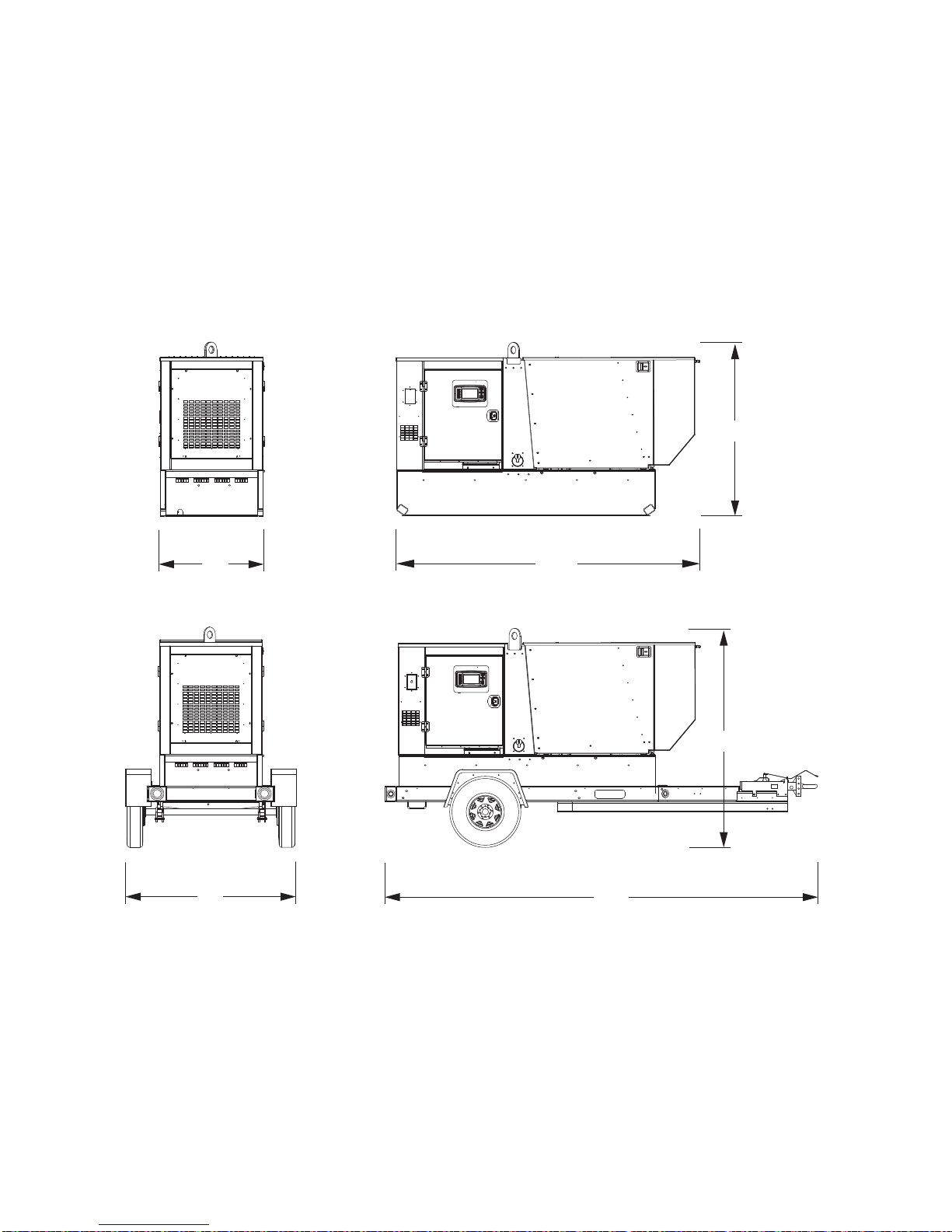
UNIT DIMENSIONS
40″
119″
68″
69″
170″
86″
Read this manual carefully before attempting to use this generator. The potential for property damage, personal
injury or death exists if this equipment is misused or installed incorrectly. Read all of the manuals included with this
unit. Each manual details specific information regarding items such as set up, use and service requirements.
SPECIFICATIONS ARE SUBJECT TO CHANGE WITHOUT NOTICE.
MAGNUM MODEL MMG75D/100D
Dimensions (L x W x H)
Skid Mounted in (m) ...................................................................................................... 119 x 40 x 68 (3.02 x 1.02 x 1.73)
Trailer Mounted in (m) .................................................................................................. 170 x 69 x 86 (4.32 x 1.75 x 2.18)
13
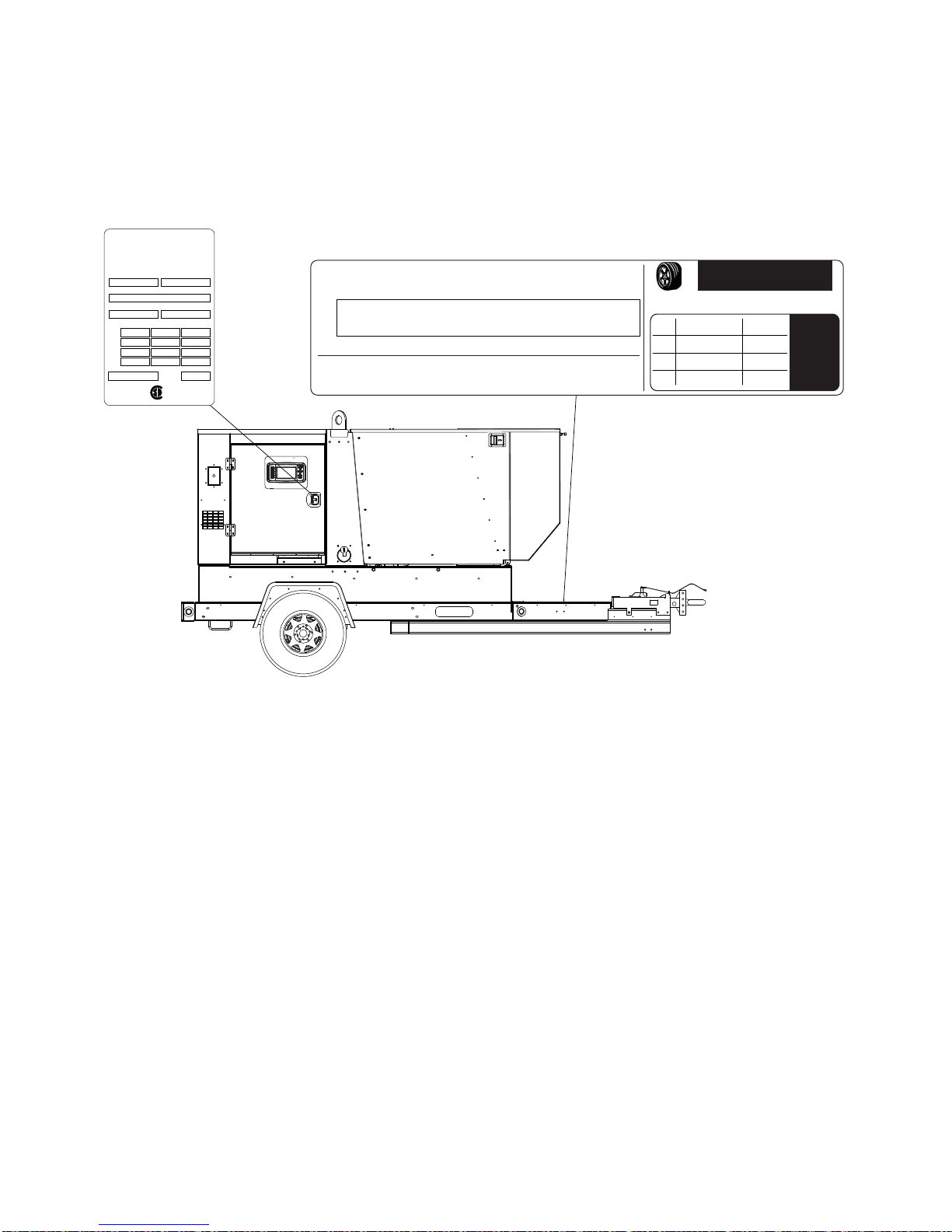
UNIT SERIAL NUMBER LOCATIONS
UNIT ID Tag
Serial Number
V
A
Model
KVA
FOR ELECTRICAL
EQUIPMENT ONLY.
POUR MATERIAL
ELECTRIQUE SEULEMENT.
Mfg. Code
Skidded WT (lbs/kg) rpm/freq
1 ph. 1.0PF 3 ph. .8PF 3 ph. 1.0PF
insul. class
RATING
KW
®
MAGNUM POWER PRODUCTS LLC
Manufactured by
A wholly owned subsidiary of
Generac Power Systems, Inc.
215 Power Drive • Berlin, WI 54923
1-800-926-9768
TIRE AND LOADING INFORMATION
RENSEIGNEMENTS SUR LES
PNEUS ET LE CHARGEMENT
SEE OWNER’S
MANUAL FOR
ADDITIONAL
INFORMATION
VOIR LE
MANUEL DE
L’USAGER
POUR
PLUS DE
RENSEIGNEMENTS
VIN Tag
MANUFACTURED BY/FABRIQUE PAR: Magnum Power Products LLC DATE: 00/0000
GVWR/PNBV: 000KG (0000LBS) COLD INF. PRESS./
PRESS. DE
V.I.N./N.I.V.:
00000000000000000
TYPE:
TRAILER
MODEL:
XXX000
GAWR / PNBE TIRE / PNEU RIM / JANTE GONF A FROID - KPA(PSI/LPC) SGL / DUAL
EACH
AXLE
THIS VEHICLE CONFORMS TO ALL APPLICABLE STANDARDS PRESCRIBED UNDER THE U.S. FEDERAL MOTOR VEHICLE SAFETY STANDARDS(FMVSS) AND CANADIAN
MOTOR VEHICLE SAFETY REGULATIONS IN EFFECT ON THE DATE OF MANUFACTURE.
CE VEHICULE EST CONFORME A TOUTES LES NORMES QUI LUI SONT APPLICABLES EN VERTU DU REGLEMENT SUR LA SECURITE DES VEHICULES AUTOMOBILES DU CANADA EN VIGUEUR A LA DATE SA
FABRICATION.
The weight of cargo should never exceed 0000KG (0000LBS)
Le poids du chargement ne doit jamais depasser 0000KG (0000LBS)
Refer to the locations illustrated below to find the unit ID tag and VIN tag on your unit. Important information, such
as the unit serial number, model number and Vehicle Identification Number (VIN) for your trailer are found on these
tags. Record the information from these tags, so it is available if the tags are lost or damaged. When ordering parts
or requesting technical service information, you will be asked to provide this information.
14
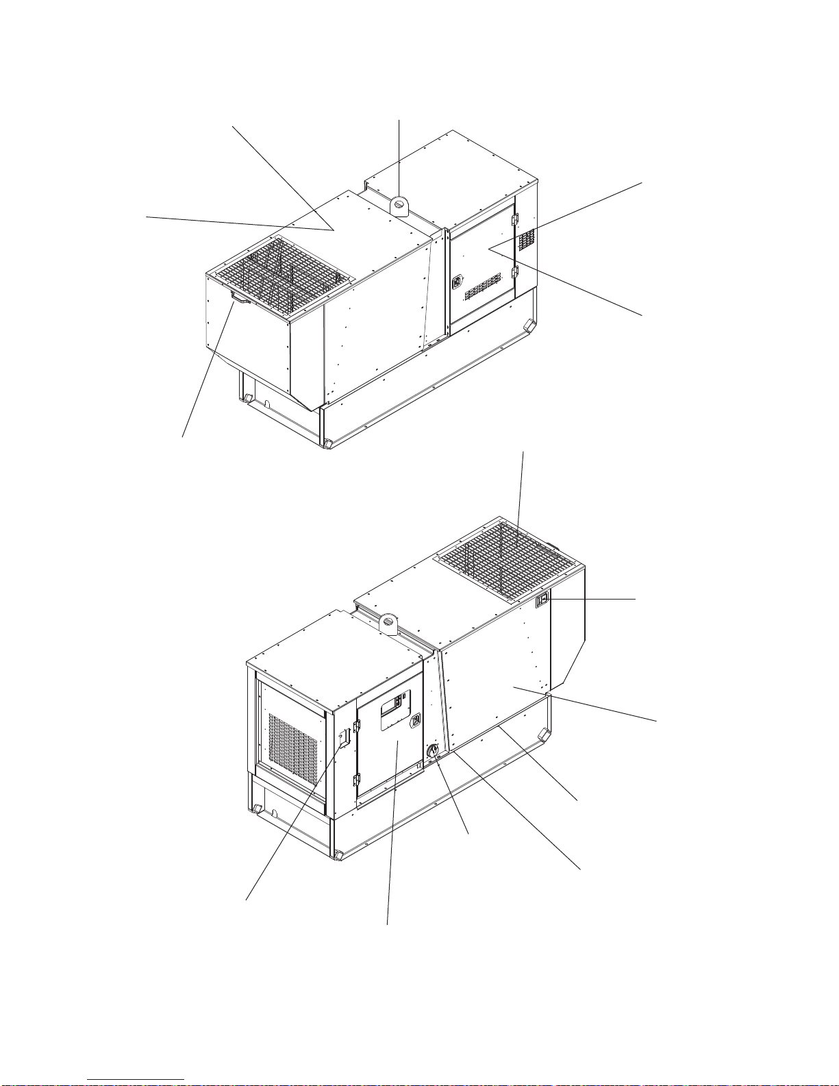
COMPONENT LOCATIONS
Radiator
Access
Engine
Access
Handle
Central
Lifting Eye
Voltage
Selector
Switch Access
Generator
Access
Engine
Exhaust
Emergency
Stop
Front Hood
Latch
Engine Battery
Access
Radiator
Drain Port
Fuel Fill
Oil Drain
Port
Control
Panel Access
15
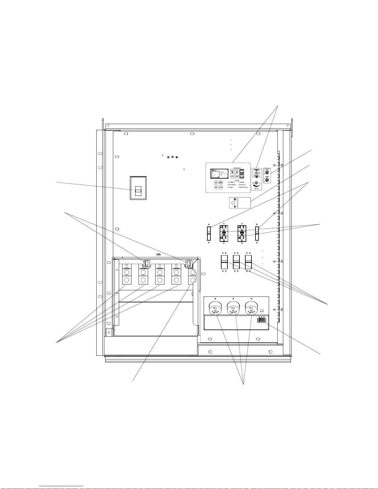
MAIN CONTROL PANEL FEATURES, STANDARD
2
5
6
7
9
10
11
1
8
4
3
12
AUTO EXHAUST
FILTER CLEANING
LIMPIEZA AUTOMÁTICA
DE FILTRO DE ESCAPE
AUTOMATISCHE
ABGASFILTERREINIGUNG
NETTOYAGE DU FILTRE
D’ÉCHAPPEMENT AUTO
ENABLE
EINSCHALTEN
ACTIVAR
ACTIVER
DISABLE
AUSSCHALTEN
DESACTIVAR
DÉSACTIVER
16

1. MAIN CIRCUIT BREAKER: This breaker will disconnect power to the connection lugs (items 10-11). It WILL
NOT disconnect power to the convenience outlets when the engine is running.
2. MAGNUM DIGITAL CONTROLLER (MDC): Refer to “Magnum Digital Controller (MDC)” on page 18 .
3. AUXILLIARY LIGHT SWITCHES (OPTIONAL): These switches operate the control panel and interior lights.
4. DIESEL EXHAUST FIL TER CLEANING SWITCH: This switch toggles between enabling and disabling the auto
exhaust cleaning feature and entering manual regeneration. Refer to page “Exhaust Filter Cleaning Oper ations”
on page 28.
5. 20A CIRCUIT BREAKERS (2): Circuit breakters for the 120V GFCI outlets.
6. 120V GFCI DUPLEX CONVENIENCE OUTLETS (2): Outlets for additional equipment that may require Ground
Fault Circuit Interrupt (GFCI) protection.
7. 50A CIRCUIT BREAKERS (2): Circuit breakters for the 120/240V twist-lock outlets.
8. REMOTE ST ART TERMINAL BLOCK: Used to connect the generator to a dry-contact closure switch for remote
starting of the generator.
9. 120/240V TWIST-LOCK CONVENIENCE OUTLETS (3): These outlets are used for connecting additional loads
or equipment to the generator in 240 and 208 voltage selections only.
10. GENERAT OR GROUND CONNECTION LUG: This lug is for connecting a good earthen ground per local, state
or National Electric Code (NEC) guidelines before starting the generator.
11. GENERATOR OUTPUT CONNECTION LUGS: These lugs allow appropriate loads to be wired directly to the
generator.
12. DOOR SAFETY SWITCHES: The connection lug door is equipped with safety interlock switches that will trip
the main circuit breaker and disable the voltage regulator if the door is opened while the unit is operating.
17
 Loading...