

Magnum IAI9SE, MLT3060, MLT3080 User Manual
LIGHT TOWER
MLT3060 • MLT3080
OPERATING/PARTS MANUAL

INTRODUCTION
This manual provides information and procedures to safely operate and maintain the engine and generator. For your
own safety and protection from physical injury, carefully read, understand and observe the safety instructions
described in this manual. The information contained in this manual was based on machines in production at the time
of publication. Magnum Products LLC reserves the right to change any portion of this information without notice.
DO NOT MODIFY or use this equipment for any application other than which it was designed for.
Magnum Products LLC recommends that a trained and licensed professional perform all electrical wiring and testing
functions. Any wiring should be in compliance with the United States National Electric Code (NEC), state and local
codes and Occupational Safety and Health Association (OSHA) guidelines.
Keep a copy of this manual with the unit at all times. Additional copies are available from Magnum Products LLC, or
can be found at www.m-p-llc.com. An engine operator’s manual was also supplied with the unit at the time of
shipment from the factory. The manual provides detailed operation and maintenance procedures for the engine.
Additional copies of the engine operators manual are available from the engine manufacturer.
MAGNUM PRODUCTS LLC
215 Power Drive • Berlin, WI 54923
U.S.A.
Phone: 920-361-4442
FAX: 920-361-4416
Toll Free: 1-800-926-9768
www.m-p-llc.com
For technical or parts QUESTIONS, please contact Magnum Products’ Customer Support or
Technical Support team at 920-361-4442 or toll free at 1-800-926-9768. Please have your serial
number available.
To ORDER SERVICE PARTS, please contact the dealer from which you purchased the unit, or call
Magnum Products to locate a dealer in your area.
Engine Make:__________________________________________
Engine Serial Number:___________________________________
Engine Model Number: __________________________________
Generator Make: _______________________________________
Generator Model Number: ________________________________
Generator Serial Number: ________________________________
Unit Model Number:_____________________________________
Unit Serial Number: _____________________________________
CALIFORNIA PROPOSITION 65 WARNING: Diesel engine exhaust and some of its
constituents are known to the state of California to cause cancer, birth defects and
2
WARNING
other reproductive harm.

TABLE OF CONTENTS
INTRODUCTION ............................................................................................................................... 2
TABLE OF CONTENTS ..................................................................................................................... 3
SAFETY NOTES ............................................................................................................................... 4
OPERATING SAFETY ....................................................................................................................... 4
ENGINE SAFETY .............................................................................................................................. 5
SERVICE SAFETY ............................................................................................................................ 5
TOWING SAFETY ............................................................................................................................. 6
REPORTING TRAILER SAFETY DEFECTS .................................................................................... 6
UNIT SERIAL NUMBER LOCATIONS .............................................................................................. 7
SAFETY SYMBOL SUMMARY ......................................................................................................... 7
SPECIFICATIONS ...................................................................................................................... 8 - 11
LIGHT TOWER SET UP .................................................................................................................. 12
RAISING THE TOWER ................................................................................................................... 13
RAISING THE TOWER WITH THE OPTIONAL ELECTRIC WINCH .............................................. 14
MAIN CONTROL PANEL COMPONENTS ...................................................................................... 15
ENGINE STARTING AND OPERATION ......................................................................................... 16
AUTOMATIC SHUTDOWN .............................................................................................................. 16
LIGHT OPERATION ........................................................................................................................ 17
AUXILIARY OUTLETS .................................................................................................................... 17
DERATING FOR ALTITUDE ............................................................................................................ 17
SHUTTING DOWN .......................................................................................................................... 18
LOWERING THE TOWER ............................................................................................................. 18
LOWERING THE TOWER EQUIPPED WITH THE OPTIONAL ELECTRIC WINCH ..................... 18
REMOVING THE LIGHTS FOR TRANSPORTATION ..................................................................... 19
TOWING THE TRAILER ................................................................................................................. 19
LIFTING THE TRAILER .................................................................................................................. 20
DAILY INSPECTION ....................................................................................................................... 20
ENGINE MAINTENANCE ................................................................................................................ 21
OPTIONAL LOWER RADIATOR HOSE HEATER USE AND MAINTENANCE .............................. 21
TROUBLESHOOTING THE LIGHTS .............................................................................................. 22
UNIT DECALS .......................................................................................................................... 23 - 27
MANUAL WINCH MAST ASSEMBLY ...................................................................................... 28 - 29
ELECTRIC WINCH MAST ASSEMBLY ................................................................................... 30 - 31
FRAME AND COMPONENTS .................................................................................................. 32 - 33
MAIN ENCLOSURE COMPONENTS ...................................................................................... 34 - 35
MITSUBISHI ENGINE ASSEMBLY .......................................................................................... 36 - 37
KUBOTA ENGINE ASSEMBLY ................................................................................................ 38 - 39
CONTROL PANEL ASSEMBLY ...................................................................................................... 40
CONTROL BOX ASSEMBLY .......................................................................................................... 41
OVAL LIGHT ASSEMBLY ........................................................................................................ 42
RECTANGULAR LIGHT ASSEMBLY ...................................................................................... 44 - 45
ROUND LIGHT ASSEMBLY .................................................................................................... 46 - 47
SPORE RECTANGULAR LIGHT ASSEMBLY .........................................................................48 - 49
MAST JUNCTION BOX ASSEMBLY - QUICK DISCONNECT LIGHTS ......................................... 50
MAST JUNCTION BOX ASSEMBLY - HARD WIRED LIGHTS ...................................................... 51
METAL HALIDE BALLAST BOX ASSEMBLY ................................................................................. 52
HIGH PRESSURE SODIUM BALLAST BOX ASSEMBLY .............................................................. 53
6 KW GENERATOR ASSEMBLY .................................................................................................... 54
8 KW GENERATOR ASSEMBLY .................................................................................................... 55
AC WIRING DIAGRAM - MLT3060 ................................................................................................. 56
AC WIRING DIAGRAM - MLT3080 ................................................................................................. 57
DC WIRING DIAGRAM - MITSUBISHI ........................................................................................... 58
DC WIRING DIAGRAM - KUBOTA .......................................................................................... 59 - 60
DC CIRCUIT WIRING DIAGRAM - DUAL ELECTRIC WINCH ....................................................... 61
MAST JUNCTION BOX WIRING .................................................................................................... 62
Page
- 43
3
SAFETY NOTES
DANGER
CAUTION
This is the safety alert symbol. It is used to alert you to potential personal injury hazards. Obey all
safety messages that follow this symbol to avoid possible injury or death.
This manual contains DANGERS, WARNINGS, CAUTIONS, NOTICES and NOTES which must be
followed to prevent the possibility of improper service, damage to the equipment, personal injury or death.
The following formatting options will apply when calling the readers attention to the DANGERS, WARNINGS, CAUTIONS, NOTICES and NOTES.
INDICATES A HAZARDOUS SITUATION WHICH, IF NOT AVOIDED, WILL RESULT IN
Indicates a hazardous situation which, if not avoided, could result in death or serious
Indicates a hazardous situation which, if not avoided, may result in minor or moderate injury.
Indicates a hazardous situation which, if not avoided, may result in property or equipment
DEATH OR SERIOUS INJURY.
WARNING
injury.
damage.
Note: Notes contain additional information important to a procedure and will be found within the regular text body
of this manual.
OPERATING SAFETY
Before using the light tower be sure you read and understand all of the instructions! This equipment was
designed for specific applications; DO NOT modify or use this equipment for any application other than
which it was designed for. Equipment operated improperly or by untrained personnel can be dangerous!
Read the operating instructions and familiarize yourself with the location and proper use of all instruments
and controls. Inexperienced operators should receive instruction from someone familiar with the equipment
before being allowed to operate or set up the light tower. The following points should be practiced at all times:
• The area immediately surrounding the light tower should be dry, clean, and free of debris.
• Position and operate the light tower on a firm, level surface.
• NEVER start a unit in need of repair.
• Lower tower when not in use, or if high winds or electrical storms are expected in the area.
• Make certain light tower is well grounded and securely fastened to a good earthen ground.
• The tower extends up to 30 ft. (9m). Make sure area above trailer is open and clear of overhead wires
and obstructions.
• Bulbs become extremely hot in use! Allow bulb and light fixture to cool 10-15 minutes before handling.
• Keep area behind trailer clear of people while raising and lowering mast!
• NEVER raise, lower or turn mast while unit is operating!
• Trailer must be leveled and outriggers extended before raising tower. Outriggers must remain extended
while tower is up.
• If for any reason any part of mast hangs up or winch cable develops slack while raising or lowering
tower, STOP immediately! Contact an authorized service representative.
• NEVER remove safety pin or pull mast locking pin while tower is up!
4

• NEVER use tower if insulation on electrical cord is cut or worn through.
• NEVER operate lights without protective lens cover in place or with a lens cover that is cracked or
damaged!
ENGINE SAFETY
Internal combustion engines present special hazards during operation and fueling! Failure to follow the
safety guidelines described below could result in severe injury or death. Also read and follow all safety
warnings described in the Engine Operator's Manual. A copy of this manual was supplied with unit when
it was shipped from the factory.
• DO NOT run engine indoors or in an area with poor ventilation unless exhaust hoses are used. Diesel
engine exhaust contains carbon monoxide, a deadly, odorless and colorless gas which, if inhaled,
can cause nausea, fainting or death. Make sure engine exhaust cannot seep into closed rooms or
ventilation equipment.
• DO NOT Operate the unit on a combustible surface.
• DO NOT fill fuel tank near an open flame, while smoking, or while engine is running. DO NOT fill tank
in an enclosed area with poor ventilation.
• DO NOT operate with the fuel tank cap loose or missing.
• DO NOT touch or lean against hot exhaust pipes or engine cylinders.
• DO NOT clean air filter with gasoline or other types of low flash point solvents.
• DO NOT remove engine coolant cap while engine is hot.
• DO NOT operate the unit without a functional exhaust system. Prolonged exposure to sound levels
in excess of 85 DBA can cause permanent hearing loss. Wear hearing protection when working around
a running engine.
• Keep area around exhaust pipes and air ducts free of debris to reduce the chance of an accidental fire.
• Batteries contain sulfuric acid which can cause severe injury or death. Sulfuric acid can cause eye
damage, burn flesh or eat holes in clothing. Protective eye wear and clothing are necessary when
working on or around the battery. Always disconnect the NEGATIVE (-) battery cable from the
corresponding terminal before performing any service on the engine or other components.
• Shut the engine down if any of the following conditions exist during operation:
1. Noticeable change in engine speed.
2. Loss of electrical output.
3. Equipment connected to the generator overheats.
4. Sparking occurs.
5. Engine misfires or there is excessive engine/generator vibration.
6. Protective covers are loose or missing.
7. If the ambient air temperature is above 110° F.
SERVICE SAFETY
This unit uses high voltage circuits capable of causing serious injury or death. Only a qualified electrician
should troubleshoot or repair electrical problems occurring in this equipment.
• Before servicing light tower, make sure the engine start switch is turned to OFF, circuit breakers are
open (off) and the negative terminal on the battery is disconnected. NEVER perform even routine
service (oil/filter changes, cleaning, etc.) unless all electrical components are shut down.
• NEVER allow water to accumulate around the base of the light tower. If water is present, DO NOT
service!
5

• NEVER service electrical components if clothing or skin is wet. If the unit is stored outside, check the
engine and generator for any moisture and dry the unit before use.
• NEVER wash the unit with a power washer or high pressure hose.
• Open main circuit breaker before disconnecting battery cables.
• Keep hands, feet, and loose clothing away from moving parts on generator and engine.
• Make sure slings, chains, hooks, ramps, jacks, and other types of lifting devices are attached securely
and have enough weight-bearing capacity to lift or hold the equipment safely. Always remain aware
of the position of other people around you when lifting the equipment.
TOWING SAFETY
Towing a trailer requires care! Both the trailer and vehicle must be in good condition and securely fastened
to each other to reduce the possibility of an accident. Also, some states require that large trailers be
registered and licensed. Contact your local Department of Transportation office to check on license
requirements for your particular unit.
• Check that the hitch and coupling on the towing vehicle are rated equal to, or greater than, the trailer's
“gross vehicle weight rating” (GVWR).
• Check tires on trailer for tread wear, inflation, and condition.
• Inspect the hitch and coupling for wear or damage. DO NOT tow trailer using defective parts!
• Make sure the trailer hitch and the coupling are compatible. Make sure the coupling is securely fastened
to the vehicle.
• Connect safety chains in a crossing pattern under the tongue and attach the breakaway cable TO
THE REAR BUMPER OF THE TOWING VEHICLE. Do not attach the cable to the trailer hitch.
• Make sure directional and brake lights on the trailer are connected and working properly.
• Check that all lug nuts holding wheels on are tight and that none are missing.
• Maximum recommended speed for highway towing is 45 m.p.h. Recommended off-road towing speed
is not to exceed 10 m.p.h. or less depending on terrain.
When towing, maintain extra space between vehicles and avoid soft shoulders, curbs and sudden lane
changes. If you have not pulled a trailer before, practice turning, stopping, and backing up in an area away
from heavy traffic.
A film of grease on the coupler will extend coupler life and eliminate squeaking. Wipe the coupler clean
and apply fresh grease each time the trailer is towed.
REPORTING TRAILER SAFETY DEFECTS
If you believe your trailer has a defect which could cause a crash or could cause injury or death, you should immediately
inform the National Highway Traffic Safety Administration (NHTSA) in addition to notifying Magnum Products LLC.
If NHTSA receives similar complaints, it may open an investigation; and if it finds that a safety defect exists in a group
of vehicles, it may order a recall and remedy campaign. However, NHTSA cannot become involved in individual
problem between you, your dealer, or Magnum Products LLC.
To contact NHTSA, you may either call the Auto Safety Hotline toll-free at 1-888-327-4236 (TTY:1-800-424-9153),
go to http://www.safercar.gov; or write to:
Administrator
NHTSA
1200 New Jersey Avenue S.E.
Washington, DC 20590
You can also obtain other information about motor vehicle safety from http://www.safercar.gov.
6
UNIT SERIAL NUMBER LOCATIONS
MANUFACTURED BY/FABRIQUE PAR:
GVWR/PNBV:
DATE OF MFG:
COLD INFL. PRESS./PRESS.
DE GONF A FROID
GAWR/PNBE TIRE/PNEU RIM/JANTE
KPA(PSI/LPC)
SGL/DUAL
THIS VIEHICLE CONFORS TO ALL APPLICABLE STANDARDS PRESCRIBED UNDER THE CANADIAN MOTOR VIEHICLE SAFETY REGULATIONS
IN ECCEFT ON THE DATE OF MANUFACTURE. / CE VEHICULE EST CONFORME A TOUTES LES NORMES QUI LUI SONT APPLICABLES EN
VERTU DU REGLEMENT SUR LA VEHICULES DES AUTOMOBILES DU CANADA EN VIGUEUR A LA DATE SA FABRICATION.
THIS VIEHICLE CONFORMS TO ALL APPLICABLE U.S. FEDERAL MOTOR VEHICLE SAFETY STANDARDS (FMVSS) IN EFFECT ON THE DATE OF
MANUFACTURE SHOWN ABOVE.
V.I.N./N.I.V.: TYPE/TYPE DE VEHICULE:
V.I.N. Tag
Unit I.D. Tag
Located on inside
of panel
Serial Number
kg
lbs
rpm hz amb. temp.
V
A
Model
RATING: CONT. STAND BY
3 Phase
1 Phase
KVA
LR 114630-1
FOR ELECTRICAL
EQUIPMENT ONLY.
POUR MATERIAL
ELECTRIQUE SEULEMENT.
MADE IN USA
PRODUCTS LLC
215 Power Drive
Berlin, WI 54923
1-800-926-9768
TM
Mfg. Code
V
A
KW
®
UV
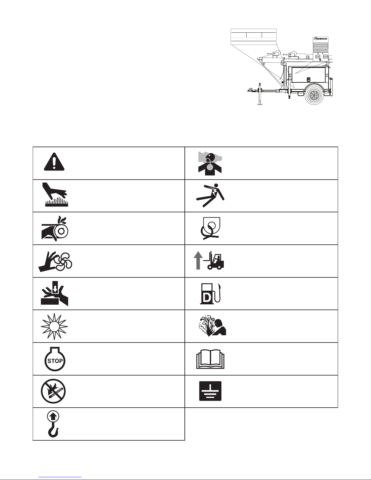
Hot surface(s) nearby.
Fire/explosion hazard; Keep
open flames away from unit.
Read and understand the
supplied operator’s manual
before operating unit.
Ultraviolet radiation hazard;
Operate only with lens intact.
Use clean diesel fuel only.
Unit electrical ground.
Anchor/tie down point.
Lift here only.
Asphyxiation hazard; Operate
in well ventilated area.
Dangerous voltage may be
present.
Crush hazard; Keep body parts
clear of this area.
Burn/scald hazard;
pressurized steam.
Fan hazard; Keep body parts
clear of this area.
Forklift here only.
Belt/entanglement hazard; Keep
body parts clear of this area.
Safety alert symbol; Used to
alert you to potential personal
injury hazards.
Stop engine before fueling.
Refer to the locations illustrated below to find the unit ID tag, and trailer
ID tag on your unit. Important information, such as the unit serial number,
model number and Vehicle Identification Number (V.I.N.) for your trailer
are found on these tags. Record the information from these tags, so it is
available if the tags are lost or damaged. When ordering parts or
requesting technical service information, you may be asked to specify
this information.
SAFETY SYMBOL SUMMARY
This equipment has been supplied with numerous safety and operating decals. These decals provide important
operating instructions and warn of dangers and hazards. Replace any missing or hard-to-read decals and use care
when washing or cleaning the unit. Decal placement and part numbers can be found in the beginning of the parts
section of this manual. Below is a summary of the intended meanings for the symbols used on the decals.
7

SPECIFICATIONS
Read this manual carefully before attempting to use this light tower. The potential for property damage, personal
injury or death exists if this equipment is misused or installed incorrectly. Read all of the manuals included with this
unit. Each manual details specific information regarding items such as set up, use and service requirements.
Specifications are subject to change without notice.
MAGNUM MODEL MLT3060 MLT3060
Engine
Make/Brand.............................................................. MITSUBISHI ................................ KUBOTA
Model ...................................................................L3E-W261ML (end S#081484) .......D905-E2BG
L3E-W461ML
Type .........................................................................Diesel, liquid cooled, 4-stroke ...... Diesel, liquid cooled, 4-stroke
Horsepower - prime hp (kW) ..................................11.0 (8.2)...................................... 10.5 (7.8)
Horsepower - standby hp (kW) ............................... 12.2 (9.1)...................................... 11.9 (8.9)
Operating Speed rpm .............................................1800 ............................................. 1800
Displacement in3 (L) ...........................................57.97 (0.95) ................................54.92 (.90)
Cylinders - qty ..........................................................3 ................................................... 3
Fuel Consumption - 100% prime gph (Lph) ...........0.47 (1.78).................................... 0.50 (1.89)
Battery Type - Group Number.................................. 24 ................................................. 24
Battery Voltage (Quantity per Unit) ..........................12V (1) ......................................... 12V (1)
Battery Rating ..........................................................440 CCA....................................... 440 CCA
Generator
Make/Brand.............................................................. Marathon Electric ......................... Marathon Electric
Model ....................................................................... 201CSA5411 ................................ 201CSA5411
Type, Insulation........................................................ Brushless, F ................................. Brushless, F
(start S#081485)
Generator Set (Engine/Generator)
Output kW (kVA) ..................................................... 6.0 (6.0) ........................................ 6.0 (6.0)
Output Voltage V .....................................................120/240, single phase .................. 120/240, single phase
Output Amperes 120V (240V) A ............................. 50 (25).......................................... 50 (25)
Frequency Hz ..........................................................60 ................................................. 60
Power Factor............................................................ 1 (1Ø) ........................................... 1 (1Ø)
Weights
Dry Weight lbs (kg) .................................................1640 (744) .................................... 1657 (752)
Operating Weight lbs (kg) ......................................1853 (841).................................... 1870 (848)
Capacities
Fuel Tank Volume gal (L) ........................................30 (114)........................................ 30 (114)
Usable Fuel Volume gal (L) ....................................30 (114)........................................ 30 (114)
Coolant (incl. engine) qt (L) ....................................4.5 (4.3)........................................ 4.8 (4.5)
Oil (incl. filter) qt (L) ................................................3.8 (3.6)........................................ 5.4 (5.1)
Maximum Run Time hrs .........................................64 ................................................. 60
AC Distribution
Circuit Breaker Size .................................................30 ................................................. 30
Voltage Regulation...................................................Capacitor +/-6% ........................... Capacitor +/-6%
Voltages Available 1Ø.............................................. 120, 240 ....................................... 120, 240
8

SPECIFICATIONS
Read this manual carefully before attempting to use this light tower. The potential for property damage, personal
injury or death exists if this equipment is misused or installed incorrectly. Read all of the manuals included with this
unit. Each manual details specific information regarding items such as set up, use and service requirements.
Specifications are subject to change without notice.
MAGNUM MODEL MLT3060
Lighting
Lighting Type............................................................Metal Halide
Ballast Type .............................................................Coil & Core
Lumens ....................................................................440,000
Coverage acres (m2) ..........................................5 - 7 (20,234 - 28,328)
Dimensions
Length w/ mast stowed in (m) ................................170 (4.32)
Width in (m) ............................................................49 (1.25)
Width w/ outriggers extended in (m) .......................98 (2.49)
Height w/ mast stowed in (m) .................................68 (1.73)
Maximum height of tower ft (m) .............................. 30 (9.14)
Trailer
Number of Axles ......................................................1
Capacity - Axle Rating lbs (kg) ...............................2200 (998)
Tire Size in ..............................................................13
Hitch - Standard .......................................................2" Ball
Maximum Tire Pressure psi ....................................50
9

SPECIFICATIONS
Read this manual carefully before attempting to use this light tower. The potential for property damage, personal
injury or death exists if this equipment is misused or installed incorrectly. Read all of the manuals included with this
unit. Each manual details specific information regarding items such as set up, use and service requirements.
Specifications are subject to change without notice.
MAGNUM MODEL MLT3080 MLT3080
Engine
Make/Brand.............................................................. MITSUBISHI................................. KUBOTA
Model ...................................................................L3E-W261ML (end S#081484) ........D1105-E3BG
L3E-W461ML
Type .........................................................................Diesel, liquid cooled, 4-stroke ...... Diesel, liquid cooled, 4-stroke
Horsepower - prime hp (kW) ..................................10.5 (7.8)...................................... 13.5 (10.1)
Horsepower - standby hp (kW) ............................... 12.2 (9.1)...................................... 15.4 (11.5)
Operating Speed rpm .............................................1800 ............................................. 1800
Displacement in3 (L) ...........................................57.97 (0.95) ................................68.53 (1.12)
Cylinders - qty ..........................................................3 ................................................... 3
Fuel Consumption - 100% prime gph (Lph) ...........0.63 (2.38).................................... 0.70
Battery Type - Group Number.................................. 24 ................................................. 24
Battery Voltage (Quantity per Unit) ..........................12V (1) ......................................... 12V
Battery Rating ..........................................................440 CCA....................................... 440 CCA
Generator
Make/Brand.............................................................. Marathon Electric ......................... Marathon Electric
Model ....................................................................... 332CSA5211 ................................ 332CSA5211
Type, Insulation........................................................ Brushless, F ................................. Brushless, F
(start S#081485
Generator Set (Engine/Generator)
Output kW (kVA) ..................................................... 7.3 (7.3) ........................................ 8.0 (8.0)
Output Voltage V .....................................................120/240, single phase .................. 120/240, single phase
Output Amperes 120V (240V) A ............................. 61 (30).......................................... 66 (33)
Frequency Hz ..........................................................60 ................................................. 60
Power Factor............................................................ 1 (1Ø) ........................................... 1 (1Ø)
Weights
Dry Weight lbs (kg) .................................................1662 (754) .................................... 1679 (762)
Operating Weight lbs (kg) ......................................1875 (850).................................... 1892 (859)
Capacities
Fuel Tank Volume gal (L) ........................................30 (114)........................................ 30 (114)
Usable Fuel Volume gal (L) ....................................30 (114)........................................ 30 (114)
Coolant (incl. engine) qt (L) ....................................4.5 (4.3)........................................ 4.8 (4.5)
Oil (incl. filter) qt (L) ................................................3.8 (3.6)........................................ 5.4 (5.1)
Maximum Run Time hrs .........................................48 ................................................. 43
AC Distribution
Circuit Breaker Size .................................................40 ................................................. 40
Voltage Regulation...................................................Capacitor +/-6% ........................... Capacitor +/-6%
Voltages Available 1Ø.............................................. 120, 240 ....................................... 120, 240
10

SPECIFICATIONS
Read this manual carefully before attempting to use this light tower. The potential for property damage, personal
injury or death exists if this equipment is misused or installed incorrectly. Read all of the manuals included with this
unit. Each manual details specific information regarding items such as set up, use and service requirements.
Specifications are subject to change without notice.
MAGNUM MODEL MLT3080
Lighting
Lighting Type............................................................Metal Halide
Ballast Type .............................................................Coil & Core
Lumens ....................................................................440,000
Coverage acres (m2) ..........................................5 - 7 (20,234 - 28,328)
Dimensions
Length w/ mast stowed in (m) ................................170 (4.32)
Width in (m) ............................................................49 (1.25)
Width w/ outriggers extended in (m) .......................98 (2.49)
Height w/ mast stowed in (m) .................................68 (1.73)
Maximum height of tower ft (m) .............................. 30 (9.14)
Trailer
Number of Axles ......................................................1
Capacity - Axle Rating lbs (kg) ...............................2200 (998)
Tire Size in ..............................................................13
Hitch - Standard .......................................................2" Ball
Maximum Tire Pressure psi ....................................50
11
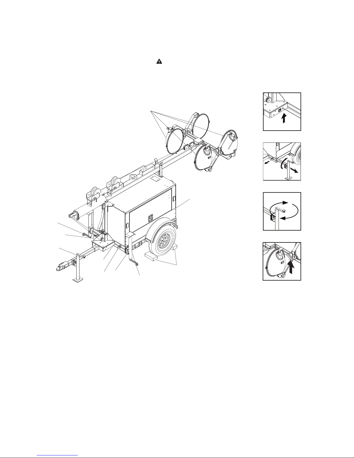
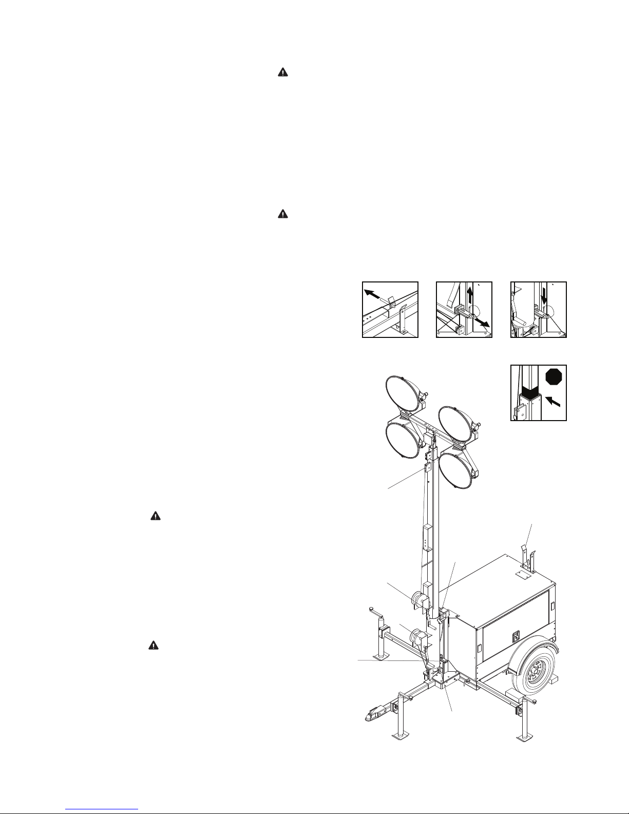
LIGHT TOWER SET UP
H
F
A
G
E
D
C
B
D
E
DETAIL C
DETAIL D
DETAIL G
DETAIL H
1. For maximum light coverage locate tower at ground level or in a spot higher than the area being illuminated by
the lamps.
WARNING
The tower extends up to 30 ft (9.14 m). Make sure area above the trailer is open and
clear of overhead wires and obstructions.
2. Place the trailer on firm ground that is relatively flat. This will make it easier to level the tower. Block the wheels
on the trailer to keep it from moving (A).
3. Pull the locking pin on the tongue jack and rotate it 90º until the spring loaded pin snaps back into place (B).
Turn the jack handle clockwise to raise the trailer tongue off of the towing vehicle.
4. Connect a good earthen ground to the grounding stud on the frame of the trailer near the trailer tongue (C).
5. Pull the locking pins (D) on the outriggers (E) and pull the outriggers out until the spring loaded locking pin snaps
back into place. Pull the locking pin on the outrigger jacks and rotate them 90º so the jack pads are facing down
and the spring loaded pin snaps back into place.
6. Pull the locking pin on the rear jack (F) and rotate it 90º until the spring loaded pin snaps back into place. Turn
the jack handle clockwise to start leveling the trailer. Adjust all four jacks by turning their handles clockwise until
they are firmly in contact with the ground and the trailer is as level as possible (G).
7. Before raising the tower it may be necessary to adjust the lamps. The lamps may be adjusted up, down, left or
right by loosening the wing nuts on the trunnion (H) and aiming the lamps in the desired direction. Tighten the
hardware completely and make sure the lamps are connected to the junction box.
12
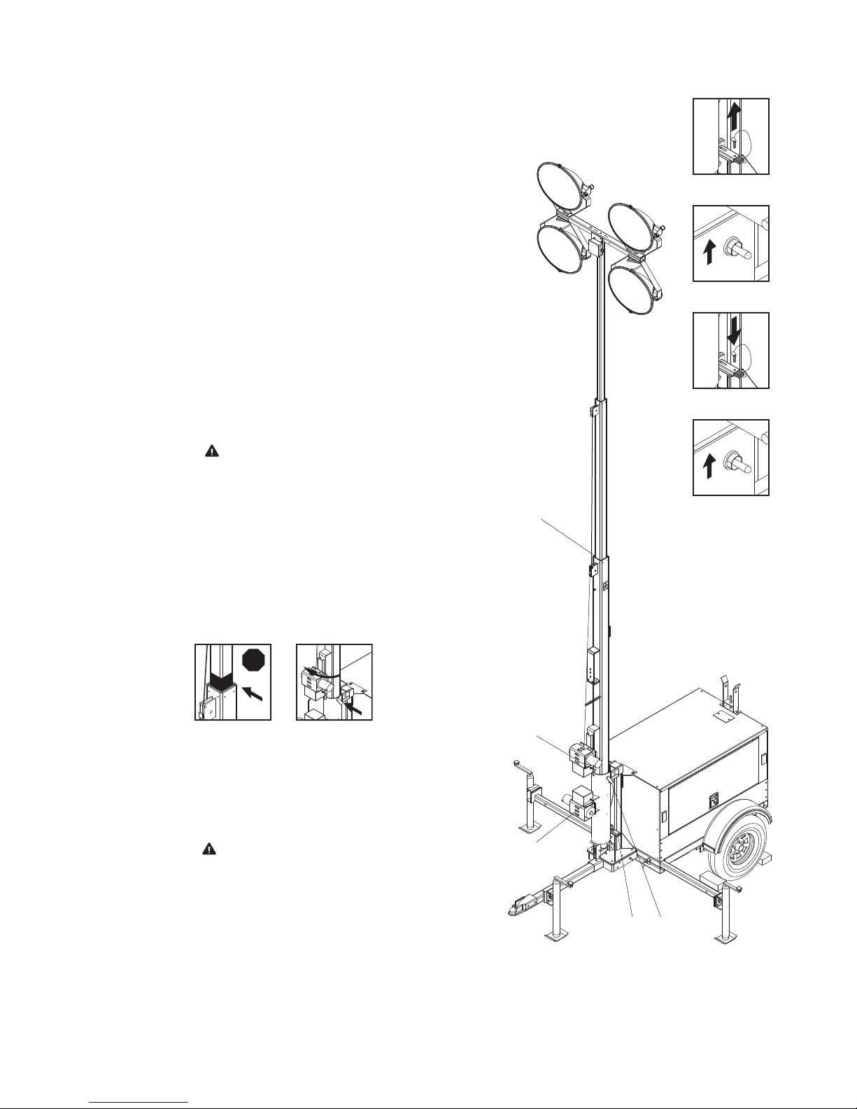
RAISING THE TOWER
CAUTION
WARNING
I
J
J
K, L, N
M
O
Q
DETAIL I DETAIL K
STOP
DETAIL N
DETAIL P
WARNING
The trailer must be leveled with the outriggers extended before raising the tower. The
outriggers must remain extended while the tower is up. Failure to level the trailer or
extend the outriggers will severely reduce the stability of the unit and could allow the
tower to tip and fall.
1. Remove the mast cradle locking pin from the mast cradle (I).
2. Check both sets of mast cables for excessive wear or damage. Make sure the cables are properly centered in
each pulley (J). Check the electrical cord for damage.
WARNING
Do not start the unit if the insulation on the electrical cord is cut or worn through.
Bare wires in contact with the mast or frame may energize the trailer and cause
electrocution. Repair or replace cord.
3. Make sure the area behind the unit is clear before
raising the mast to the vertical position.
4. Remove the safety pin (K) from the mast lock bar (L).
Using the handle for the lower mast winch (M), raise
the mast until it is vertical and the tab on the mast is
positioned into the mast lock. The mast lock bar
should snap into place automatically. Secure the
lock with the safety pin (N).
5. After the mast is up and locked into place, use the
upper mast winch (O) to telescope the tower to the
desired height. Extend the mast slowly, making sure
that the electrical cord is extending at the top sections of the mast. If, for any reason, the winch cable
begins to develop slack or any of the tower sections
get stuck, STOP IMMEDIATELY and contact an
authorized service center.
Do not extend the mast beyond
the colored mark on the middle
6. The mast can be rotated by loosening the locking
knob at the bottom of the mast (Q). Turn the mast until
the lights face in the desired direction and then
tighten the knob.
Never raise or lower the mast
while the unit is operating!
Never remove the safety pin or
mast lock while the tower is up.
Releasing the lock will cause
mast tube (P).
the mast to fall.
13
RAISING THE TOWER WITH THE OPTIONAL ELECTRIC WINCH
CAUTION
WARNING
DETAIL R
DETAIL S
DETAIL T
DETAIL U
V
U
S
R,T W
STOP
DETAIL V DETAIL W
1. Set up and level the trailer as described on page 12, and follow
steps 1-3 on page 13.
2. Remove the safety pin from the mast lock bar (R).
3. Press the lower winch control toggle switch upward to raise mast
into the vertical position (S). Hold switch until the mast lock is
engaged. The mast lock bar should snap into place automatically. Note: On light towers equippedwith the electric winch
option, a limit switch on the mast tube will disconnect power to
the lower electric winch to prevent deadheading the winch.
4. Secure the lock with the safety pin (T).
5. Press and hold the upper winch control toggle switch upward to
telescope the mast to desired height (U). Extend the mast
slowly, making sure that the coiled electrical cord is extending at
the top sections of the mast. If, for any reason, the winch cable
begins to develop slack or any of the tower sections get stuck,
STOP IMMEDIATELY and contact an authorized servicecenter.
Do not extend the mast beyond
the colored mark on top of the
lower mast section (V). On light
towers equipped with the electric
winch option, a limit switch on the
main mast section will disconnect
power to the upper electric winch
to prevent over extending the
mast.
6. The mast can be rotated by loosening the locking knob at the
bottom of the mast (W). Turn the mast until the lights face in the
desired direction andthen tighten the knob.
Never raise or lower the mast
while the unit is operating!
Never remove the safety pin or
mast lock while the tower is up.
Releasing the lock will cause
the mast to fall.
14
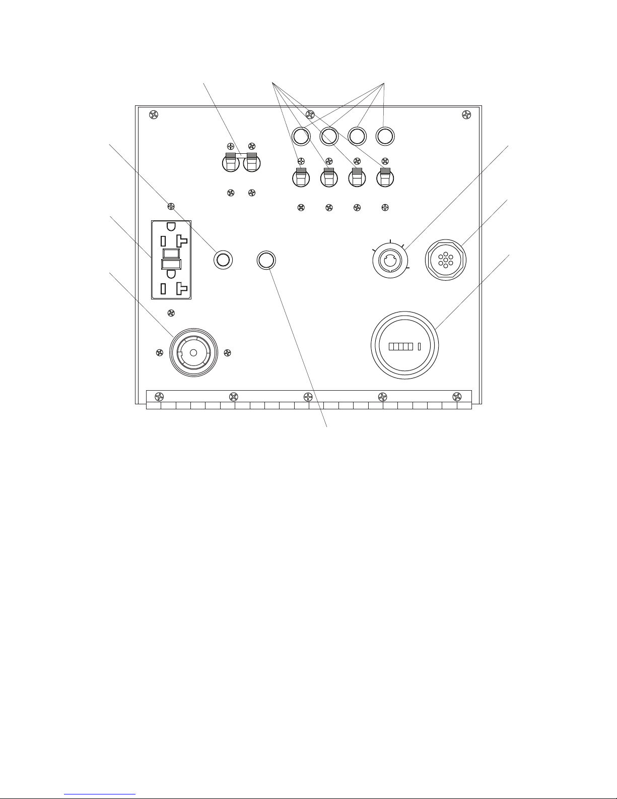
MAIN CONTROL PANEL COMPONENTS
ON
ON
MAIN
BREAKER
240V
I
O
0
0 00 0
HOURS
20
ON
ON
ON
ON
LIGHT
1
LIGHT2LIGHT
3
LIGHT
4
BALLAST INDICATOR LIGHTS
I
O
I
O
I
O
I
O
GLOW
PLUG
INDICATOR
GLOW
PLUG
OFF
RUN
START
120V
240V
NEUTRAL BONDED TO FRAME
CONDUCTOR NEUTRO
CONECTOADO AL CHASIS
TURN
MAIN
BREAKER
OFF
12 3
6
7
8
9
5
5
4
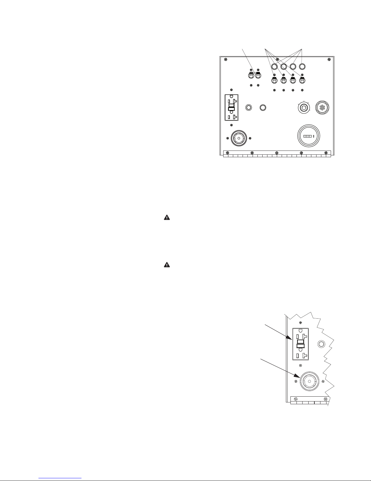
1. MAIN CIRCUIT BREAKER (30A or 40A): This breaker will disconnect power to the lights and auxiliary outlets.
It will also disable the starting circuit if engine starting is attempted when the main breaker is on.
2. INDIVIDUAL CIRCUIT BREAKERS: One breaker is supplied for each light.
3. BALLAST INDICATOR LIGHTS: Indicates power from the ballast to each light.
4. OUTLET CIRCUIT BREAKER: This breaker is supplied for the standard 120V GFCI outlet.
5. AUXILIARY OUTLETS: These outlets supply power for accessories connected to the generator when the engine
is running and the main circuit breaker is switched to the on “I” position.
6. ENGINE STARTING SWITCH: Keyed switch operates glow plugs, starts and stops engine.
7. ENGINE GLOW PLUG INDICATOR: Indicates operation of the engine glow plugs on certain engines.
8. ENGINE HOUR METER: Keeps track of engine hours for service.
9. CIRCUIT BREAKER INDICATOR LIGHT: This light indicates that the main circuit breaker must be opened
(switched off) before starting the engine.
15
ENGINE STARTING AND OPERATION
WARNING
1. Check engine oil, fuel and coolant levels. Note: If the engine was run out of fuel or the fuel tank was drained, it
may be necessary to bleed the fuel lines. Refer to the engine operation manual supplied with the unit.
2. Check the condition of the electrical cord on the inside of the unit.
WARNING
Do not start the unit if the insulation on the electrical cord is cut or worn through.
Bare wires in contact with the mast or frame may energize the trailer and cause
electrocution. Repair or replace cord.
3. Check that the main circuit breaker and individual circuit breakers for
each of the lights are in the off “O” position. Note: If the red light on
the control panel “TURN MAIN BREAKER OFF” is illuminated when
the key is turned to the “START” position, the breaker is closed
(switched on).
NEVER START THE ENGINE
WITH ANY OF THE CIRCUIT
BREAKERS SWITCHED ON!
Any load on the generator
during start up will cause
severe damage or destroy the
generator!
I
O
I
OIO
I
I
O
O
4. Turn the key on the engine start switch to the left “GLOW PLUG” position and hold the key in place until the glow
plug indicator turns red. As soon as it’s glowing turn the key to the right to the “START” position and hold it until
the engine cranks and starts running. Release the key, it will move to the “RUN” position.
RELEASE KEYACTIVATE GLOW PLUGS CRANK ENGINE TO START
GLOW
PLUG
OFF
RUN
START
GLOW
PLUG
OFF
RUN
START
GLOW
PLUG
OFF
RUN
START
Do not crank the engine longer than 10 seconds at a time. If the engine will not start, wait
30 seconds to allow the starter motor to cool and then repeat the starting procedure.
Excessive cranking will cause damage to the starter.
5. Note: If oil pressure is not obtained within 30 seconds after the key is switched to the “RUN” position, the low-
oil automatic shutdown will turn off the fuel supply, stopping the engine. Check the oil level and turn the key to
the “OFF” position to reset the oil pressure timer before attempting to restart the engine.
6. Once the engine is running, allow it to reach normal operating temperature before switching on any loads.
AUTOMATIC SHUTDOWN
This unit is equipped with a low oil pressure and high coolant temperature auto-shutdown system. This system will
automatically shut off the fuel supply to stop the engine if oil pressure drops too low or the engine exceeds normal
operating temperature. Return the switch to the “OFF” position to reset the unit after you have determined the cause
of the shutdown.
16
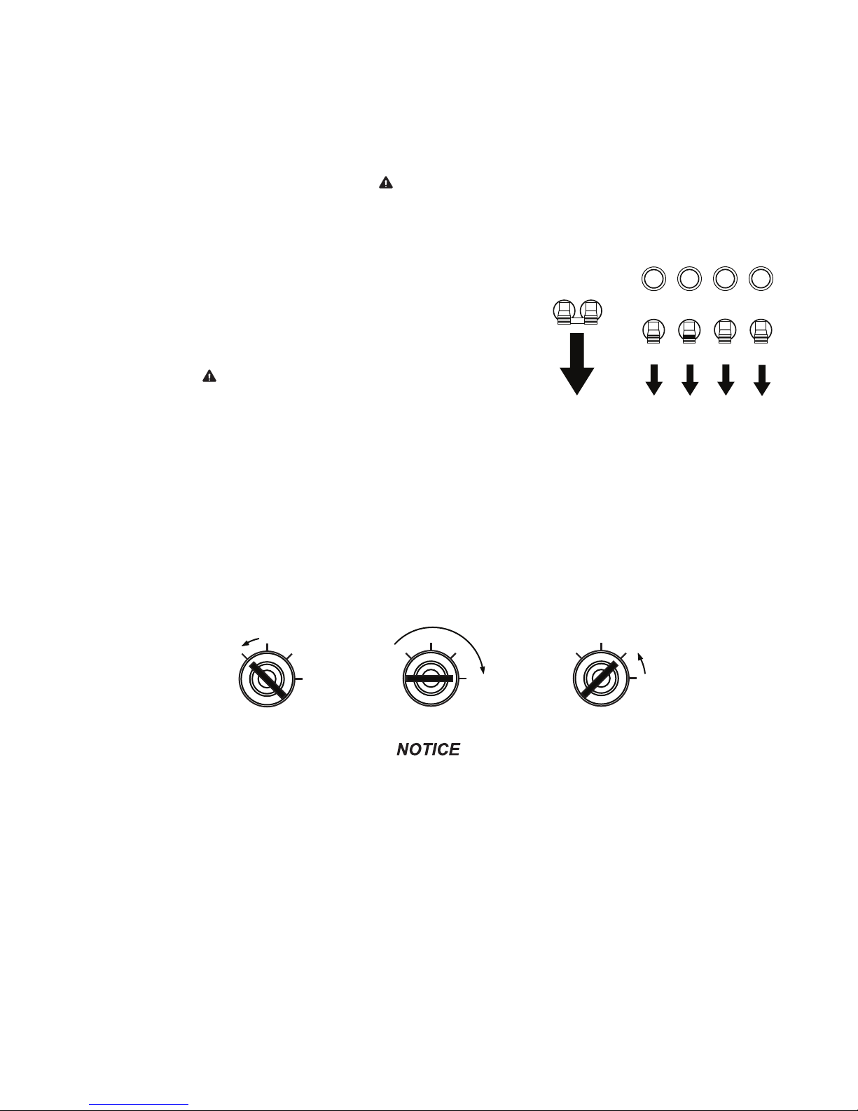
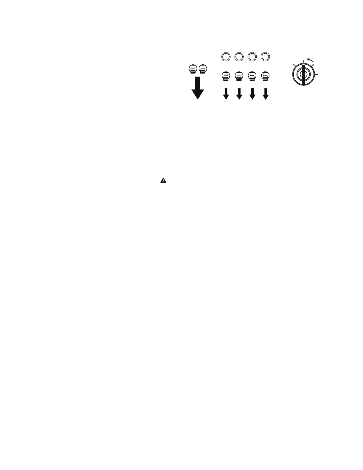
LIGHT OPERATION
1. Once the engine is up to temperature and running smoothly,
switch main circuit breaker (1) to the ON “I” position.
2. With main circuit breaker on, switch each individual circuit
breaker for the lights (2) to ON “I”, one at a time.
3. The ballast indicator lights (3) will come on momentarily as the
lights strike. As the lights warm up, the ballast indicator lights will
continue to get brighter and then remain on. This confirms that
power is coming from the ballasts to the lights.
12 3
MAIN
BREAKER
240V
I
ON
ON
O
120V
20
IOIOIOI
LIGHT
TURN
MAIN
BREAKER
OFF
BALLAST INDICATOR LIGHTS
ON
ON
LIGHT2LIGHT
1
ON
O
3
GLOW
PLUG
ON
LIGHT
4
GLOW
PLUG
INDICATOR
OFF
RUN
START
4. If an indicator light does not come on, the ballast may need to
be serviced. If the indicator light comes on and stays lit but the
related light is not illuminated, check the bulb or the mast wiring.
5. The lights require a warm up period of 5-15 minutes before they
240V
NEUTRAL BONDED TO FRAME
CONDUCTOR NEUTRO
CONECTOADO AL CHASIS
0 00 0
0
HOURS
reach full output. If the lights are shut down, they require a cooldown period of approximately 10 minutes before they can be
switched on again.
6. The light tower uses four 1000W bulbs. When checking or replacing the bulbs, wipe them with a clean cloth to
avoid leaving any grease, oil residue or fingerprints on the glass. Any residue can create a hot spot on the bulb,
causing premature bulb failure.
WARNING
NEVER OPERATE THE LIGHTS WITHOUT THE PROTECTIVE LENS COVER OR WITH
A LENS COVER THAT IS CRACKED OR DAMAGED! The bulbs in the light fixtures
produce high temperatures and operate under pressure. A broken or missing lens
cover could cause the bulbs to shatter, causing injury.
WARNING
Bulbs become extremely hot in use! Allow bulb fixture to cool 10-15 minutes before
handling.
AUXILIARY OUTLETS
The control panel is equipped with two outlets for running accessories
or tools from the generator. Power is supplied to the outlets any time
the engine is running and the main circuit breaker is switched on “I”.
Note: Do not pull more than 1000W from each outlet when the lights
are on. This will overload the generator and cause the main circuit
breaker to trip. Should the breaker trip, switch off the lights, remove
some of the load to the outlets and wait 10 minutes for the bulbs to
cool before turning them back on.
With all of the lights off, the full generator output may be used with
the 240V twist-lock outlet.
120V GFCI
OUTLET
240V TWIST-LOCK
OUTLET
120V
20
240V
DERATING FOR ALTITUDE
All light towers are subject to derating for altitude and temperature. Although derating should not affect the operation
of the lights, it will reduce the available power for operating tools and accessories connected to the auxiliary outlets.
Typical reductions in performance are 2-4% for every 1000 ft. (305 m) of elevation and 1% per 10º F (3-5º C) increase
in ambient air temperature over 72º F (22.2º C).
17
SHUTTING DOWN
WARNING
When you have finished using the light tower proceed with shut down as follows:
1. Remove any loads from the auxiliary outlets.
2. Switch the individual circuit breakers for each light
to the OFF “O” position.
I
O
I
OIOIOIO
GLOW
PLUG
OFF
RUN
START
3. Switch the main circuit breaker to the OFF “O”
position.
4. Turn the ENGINE START SWITCH to the OFF position.
LOWERING THE TOWER
1. Shut down the lights and engine. Allow the lights to cool 10-15 minutes before lowering the tower.
2. Turn the upper mast winch handle to collapse the tower to its lowest position. Make sure the electrical cord
returns to the storage tube properly.
If the mast hangs up or the winch cable begins to develop slack, STOP IMMEDIATELY!
Excess slack in the cable could cause the mast to collapse should it free up without
warning. Contact an authorized service center.
3. Loosen the mast rotation knob and rotate the tower so the mast mounted winches face the front of the unit. The
white alignment arrow points should line up on the mast sections and the metal stop tabs should be touching.
Tighten the mast rotation knob.
4. Release the mast lock by pulling the safety pin on the mast lock and pulling the lock free. Turn the handle of the
lower mast winch until the mast spring begins to pivot the tower down. Release the mast lock and continue to
lower the tower until it rests in the cradle. Note: If the mast lock does not pull free, operate lower winch slightly
to relieve pressure on the mast lock.
5. After the mast is completely down, insert the cradle lock pin and secure it with the safety pin.
6. Position lights to aim at the ground. If the trailer is going to be moved, Magnum Products LLC strongly recommends
that the lights be removed from the mast and stowed for transportation. See REMOVING THE LIGHTS FOR
TRANSPORTATION section on page 19.
LOWERING THE TOWER EQUIPPED WITH THE OPTIONAL ELECTRIC WINCH
1. Shut down the lights and engine. Allow the lights to cool 10-15 minutes before lowering the tower.
2. Loosen the mast rotation knob and rotate the tower so the mast mounted winches face the front of the unit. The
white alignment arrow points should line up on the mast sections and the metal stop tabs should be touching.
Tighten the mast rotation knob.
3. Press and hold the upper winch control toggle switch downward to collapse the mast to its lowest level. Make
sure the coiled electrical cord on the top sections of the mast does not get tangled on the mast sections. Note:
Some electric winch models are equipped with an anti-backlash safety limit switch. This switch will disconnect
power to the winch if excess cable slack is detected, preventing accidental lowering of the tower. If, for any
reason, the cable begins to develop slack or any of the tower sections get stuck, STOP IMMEDIATELY and
contact an authorized service center.
18
4. Release the mast lock bar by pulling the safety pin on the mast lock and pulling the lock bar free. Lower the mast
by holding the lower winch control toggle switch to the right until the mast is resting in the transport cradle. Note:
If the lock bar does not pull free, activate lower winch slightly to relieve pressure on the mast lock bar.
5. After the mast is completely down, insert the cradle lock pin and secure it with the safety pin.
6. Position lights to aim at the ground. If the trailer is going to be moved, Magnum Products LLC strongly recommends
that the lights be removed from the mast and stowed for transportation.
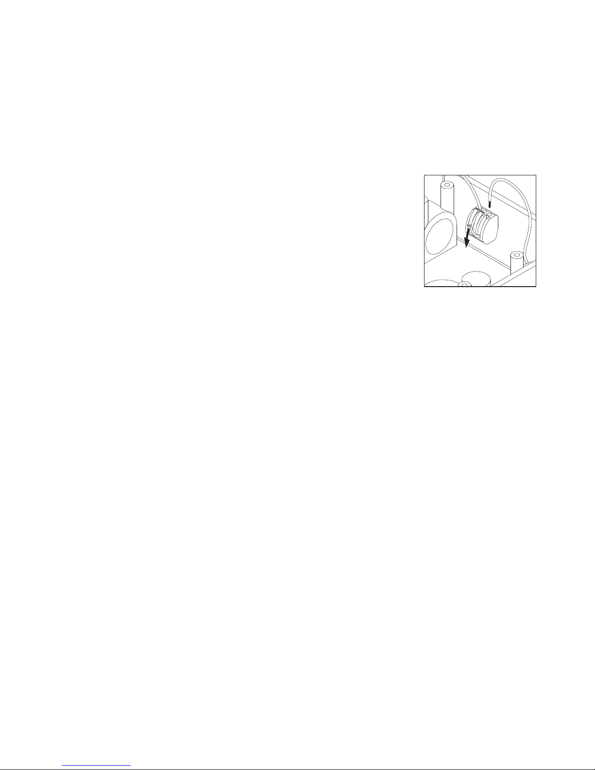
REMOVING THE LIGHTS FOR TRANSPORTATION
1. On units equipped with quick disconnect fittings for the lights, disconnect the power
cords from the junction box at the top of the mast. Replace the dust caps on the
junction box. On other units, remove the junction box cover on the top of the mast
and disconnect ONLY the mast light wires from the terminal blocks. To release
the wires from the terminal blocks, flip the locking levers down and pull out the
appropriate wires (A).
2. Remove the lights by removing the wing nut that holds the light fixture bracket to
the cross tube. Attach the lights to the storage brackets (if equipped) located on
the mast tube on either side of the central lifting eye.
TOWING THE TRAILER
Once the engine is shut down and the mast and lights are properly stowed, the trailer can be made ready for transport.
1. Raise the rear jack completely and release the locking pin to rotate it up into the travel position. Make sure the
locking pin snaps into place.
2. Raise the outrigger jacks completely and release the jack locking pin to swing the jacks up into the travel position.
Make sure the locking pins snap into place. Release the outrigger locking pins and slide the outriggers into the
trailer frame until the locking pins snap into place.
3. Use the drawbar jack to raise or lower the trailer onto the hitch of the towing vehicle. Lock the hitch coupling and
attach the safety chains or cables to the vehicle. Release the jack locking pin and rotate the jack into the travel
position. Make sure the locking pin snaps into place.
4. To ensure proper operation of the jacks, lube the grease fittings located on the leveling jacks.
5. Connect any trailer wiring to the tow vehicle. Check for proper operation of the stop and signal lights.
6. Make sure the cradle locking pin is in place.
7. Make sure the doors are properly latched.
8. If the trailer is going to be driven over rough ground, remove the bulbs from the light fixtures.
9. Check for proper inflation of the trailer tires. The maximum tire inflation is 50 psi.
10. Attach a red flag to the end of the mast before towing.
11. Maximum recommended speed for highway towing is 45 mph. Recommended off-road towing speed is not to
exceed 10 mph or less depending on terrain.
19
LIFTING THE TRAILER
CENTRAL
LIFTING EYE
UPPER
FORKLIFT
POCKETS
LOWER
FORKLIFT
POCKETS
5
2
3
4
1
When lifting the light tower and trailer, attach any slings, chains or hooks directly to the central lifting eye. The lifting
eye is located on the mast between the two forklift pockets.
1. Make sure the equipment being used to lift the light tower
has sufficient capacity. Note: See the unit specifications
beginning on page 9 for approximate weights.
2. Make sure the cradle locking pin is in place.
3. Always remain aware of the position of other people and
objects around you as you move the unit.
4. Use the upper or lower forklift pockets with care. Approach
the unit as perpendicular as possible to avoid any damage
to the unit. Make sure the mast winch handles or any other
obstructions are clear of the forklift tines before lifting.
DAILY INSPECTION
1. Inspect condition of electrical cords. DO NOT use light tower if insulation is cut or worn through.
2. Check that winch cables are in good condition and that they are centered on each pulley. DO NOT use a cable
that is kinked or starting to unravel.
PROPER MAST CABLE ROUTING
3. Check that the safety pins for the mast lock rod and mast lock bar are present and secured with a chain. Check
that the spring located in the mast lock bar is not broken or missing. Check the operation of the mast lock bar.
4. Check the fuel, oil and coolant levels.
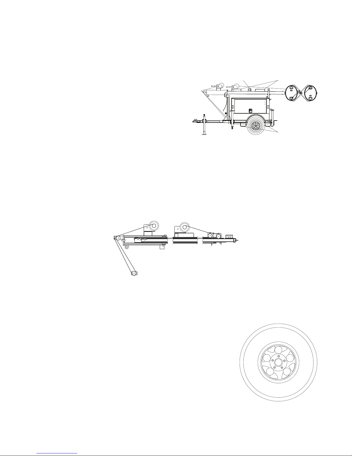
5. Check the wheel lugs. Tighten or replace any that are loose or missing. If a
tire has been removed for axle service or replaced, tighten the lugs in the
order shown, to the following specifications:
A. Start all lug nuts by hand.
B. First pass tighten to 20-25 Ft-Lbs (27-33 Nm).
C. Second pass tighten to 50-60 Ft-Lbs (67-81 Nm).
D. Third pass tighten to 90-120 Ft-Lbs (122-162 Nm).
After the first road use, retorque the lug nuts in sequence.
20
 Loading...