

Magnum MI-81350 Operating Manual

MODEL NO.:
MI-81350
OPERATING MANUAL

1
Table of contents
Page
SAFETY INSTRUCTIONS .......................... ............................. .......................... .....................2
Receiving Jointer....................................................................................................................4
Unpacking and cleaning..........................................................................................................5
Placement the 8” jointer.......................................................................................................5
Magnetic Switch......................................................................................................................6
Installation Blade Guard & Removal.......................................................................................6
Grounding Instructions............................................................................................................9
Adjustments..........................................................................................................................10
Fence Adjustments: Tilt .......................................................................................................13
Helical Cutterhead................................................................................................................14
Cutterhead Removal.............................................................................................................15
Replacement.........................................................................................................................16
Jointing Knives......................................................................................................................16
Replacement the Belts..........................................................................................................17
Basic Operations ..................................................................................................................18
Push Blocks..........................................................................................................................21
Wiring Diagrams ...................................................................................................................22
Parts Diagrams.....................................................................................................................23
Parts List...............................................................................................................................26

2
SAFETY INSTRUCTIONS
For Your Safety Read Instruction Manual Before Operating Jointer
As with all machines, there is a certai n amount of hazard involv ed with the use of this joint er. Use the machine with
the respect and caution demanded where safety precautions are concerned. When normal safety precautions
are overlooked or ignored, personal injury to the operator can result.
Wear eye protection.
Always keep cutter head and drive guards in place and in proper operating condition. Do not remove guard
for rabbeting operations.
Never make jointing , planning, or rabbeting cut deeper than 1/8 in.
Always use hold-down/push blocks for jointing material narrower than 3 inches, or planning material thinner
than 3inches.
Never perform jointing. Planning, or rabbeting cuts (with jointers provided with a rabbeting guard) on pieces
shorter than 8 inches (203 mm) in length.
Keep guards in place and in working order.
Remove adjusting keys and wrenches. Form habit of checking to see that keys and adjusting wrenches are
removed from tool before turning it on .
Keep work area clean. Cluttered areas and benches invite accidents.
Don’t use in dangerous environment. Don’t use power tools in damp or wet locations, or expose them to
rain. Keep work area well lighted.
Keep children away. All visitors should be kept safe distance from work area.
Make workshop kid proof with padlocks, master switches, or by removing starter keys.
Don’t force tool. It will do the job better and safer at the rate for which it was designed.
Use right tool. Don’t force tool or attachment to do a job for which it was not designed.
Use proper extension cord. Make sure your extension cord is in good condition. When using an extension
cord, be sure to use one heavy enough to carry the current your product will draw. An undersized cord will
cause a drop in line voltage resulting in loss of power and overheating Table (see Figure 9) shows the correct
size to use depending on cord length and nameplate ampere rating. If in doubt, use the next heavier gage.
The smaller the gage number, the heavier the cord.
Wear proper apparel. Do not wear loose clothing, gloves, neckties, rings, bracelets, or other jewelry which
may get caught in moving parts. Nonslip footwear is recommended. Wear protective hair covering to contain
long hair.
Always use safety glasses. Also use face or dust mask if cutting operation is dusty. Everyday eyeglasses
only have impact resistant lenses , they are NOT sa fe t y glas s es .
Secure work. Use clamps or a vise to hold work when practical. It’s safer than using your hand and it frees
both hands to operate tool.
Don’t overreach. Keep proper footing and balance at all times.
Maintain tools with care. Keep tools sharp and clean for best and safest performance. Follow instructions for
lubricating and changing accessories.
Disconnect tools before servicing; when changing accessories, such as blades, bits, cutters, and the like.

3
Reduce the risk of unintentional starting. Make sure switch is in off position before plugging in.
Use recommended accessories. Consult the owner’s manual for recommended accessories. The use of
improper accessories may cause risk of injury to persons.
Never stand on tool. Serious injury could occur if the tool is tipped or if the cutting tool is unintentionally
contacted.
Check damaged parts. Before further use of the tools, a guard or other part that is damage d sh ould be
carefully checked to determine that it will operate properly and perform its intended function – check for
alignment of moving parts, binding of moving parts, breakage of parts, mounting , and any other conditions
that may affect its operation. A guard or other part that is damaged should be properly repaired or replaced.
Direction of feed. Feed work into a blade or cutter against the direction of rotation of the blade or cutter only.
Never leave tool running unattended. Turn power off. Don’t leave tool until it comes to a complete stop.
Do not perform jointing operation on material shorter than 8 in , narrower than 3/4 in, or less than 1/4 in thick.
Do not perform planning operation on material shorter than 8 in , narrower than 3/4 in, or wider than 8” in or
thinner than 1/2 in.
Maintain the proper relationships of infeed and outfeed table surfaces and cutter head knife path.
Support the work piece adequately at all times during operation; mqintain control of the work at all times.
Do not back the work toword the infeed table.
Do not attempt to perform an abnormal or a little-used operation without study and the use of adequate hold-
down/push blocks, jigs, fixtures, stops and the like.
Hand safety. It is good practice to move the hands
in an alternate motion from back to front as the work
continues through the cut. Never pass the hands
directly over the cutter knife. As one hand approaches
the knives remove it from the stock in an arc motion
and place it back on the stock in a position beyond
the cutterknife.
Three inch rule. When working a piece of wood on
the jointer, follow the 3 inch radius rule. The hands
must never be closer than 3 inches to the cutter head.
Health hazards. Some dust created by power
sanding, sawing, grinding, drilling and other construction activities contains chemicals known to cause cancer,
birth defects or other reproductive harm. Some examples of these chemicals are:
*
Lead from lead-based paint.
*
Crystalline silica from bricks and cement and other masonry products.
*
Arsenic and chromium from chemically-treated lumber.
Your risk from these exposures varies, depending on how often you do this type of work. To reduce your
exposure to these chemicals, work in a well-ventilated area, and work with approved safety equipment, such
as those dust masks that are specifica lly designed to filter out microscopic particles.
Familiarize yourself with the following safety notices used in this manual:
CAUTION: (This means that if precautions are not heeded, it may result in minor or moderate injury
and/or possible machine damage)
WARNING: (This means that if precautions are not heeded, it could result in serious injury or
possibly even death).
!
!
4
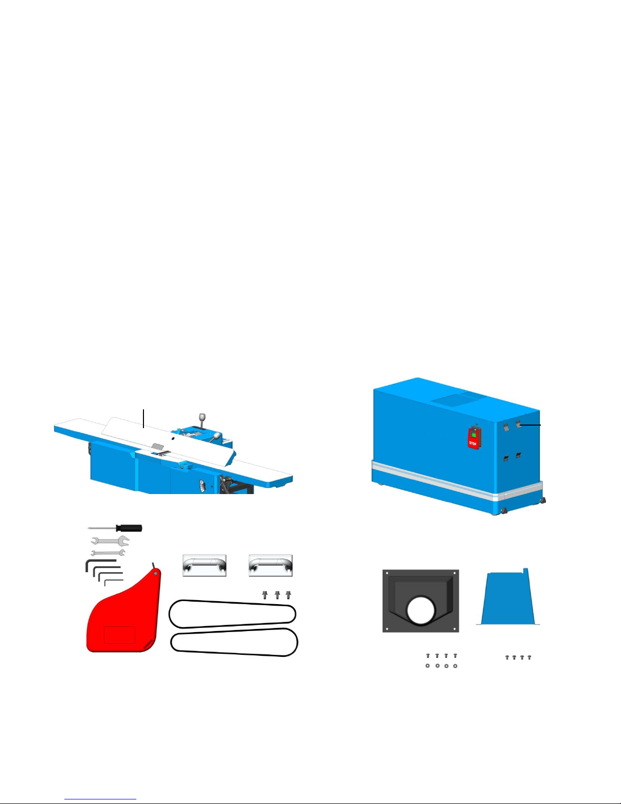
Receiving Jointer
Upon deliv e ry , o pen shippin g co nta iner s and che ck
that all parts are in good condition. Any damage
should be reported to your distributor and
shipping agent immediately. Before proceeding
further, read your manual and familiarize yourself
thoroughly with assembly, maintenance and
safety procedures.
Contents of box 1:
A. Jointer Body with F enc e Assembly..... 1
B. Blade Guard .......................................... 1
C. Push Block ............................................2
D. CAP Screw W/Spring Washer
& Flat Washer ......................................3
E. V-Belt .....................................................2
F. Screw D river.......................................... 1
G. Open Wrench 11*13..............................1
H. Open Wrench 8*10................................1
I. HEX. Wrench 8mm ...............................1
J. HEX. Wrench 6mm ...............................1
K. HE X. Wrenc h 5mm ..................................1
L. HEX. Wrench 3mm..................................1
Contents of box 2:
M. Stand................................... ...................1
N. Pulley Cover ..........................................1
O. Dust Chute.............................................1
P. Round Head Phillips Screw
W/WASHER...........................................4
Q. Round Head Phillips Screw...................4
R. Flat Washer ...........................................4
A
F
G
H
I
K
J
L
C
D
B
E
M
ON
Q
R
P
5
Unpacking and cleaning
To ensure maximum performance from your 8"
jointer, clean it properly; and install it accurately
before use. As soon as you receive the jointer,
we recommend you follow these procedures:
1. Finish removing the contents of the shipping
carton and compare with the contents list.
2. Report damage, if any to your local distributor.
3. Clean all rust protected surfaces with a mild
solvent or kerosene. Do not use lacquer
thinner; paint thinner, or gasoline. These will
damage painted surfaces.
4. To prevent rust, apply a light coating of paste
wax to surface.
Although some users prefer a wax coating for
the table surfaces, white talcum powder rubbed
in vigorously once a week with a blackboard
eraser will fill any casting pores and form a
moisture barrier. Talcum powder will not stain
wood or mar finishes.
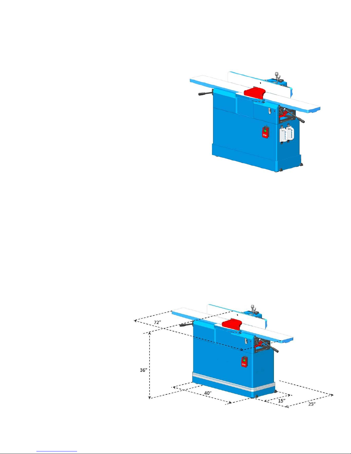
Placement the 8” jointer
This machine should be installed and operated
only on a solid, flat and stable floor that is able to
support the weight of the Jointer (366 lbs-166kgs)
and the operator.
Using the dimensions shown as below (L 66”x
W15”x H 36”), plan for placement within your
shop that will allow the operator to work
unencumbered and
unobstructed by foot traffic or
other tools or machinery.
6
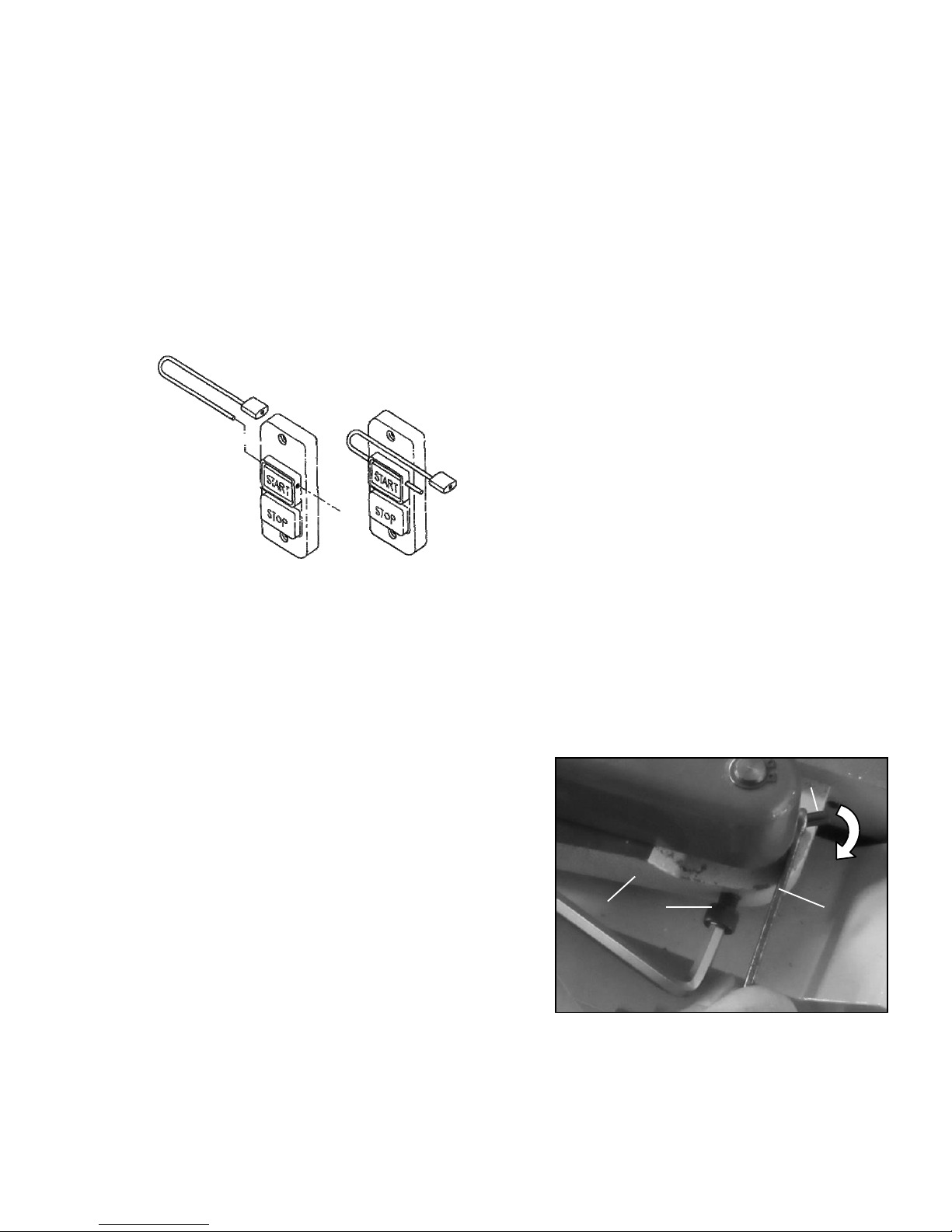
Magnetic Switch
The jointer is equipped with a magnetic switch that will accept a safety padlock (not included).
To safeguard your machine from unauthorized operation and accidental starting by young children, the use
of a padlock is required.
When you have finished using the machine be sure to re-install the lock-out pin and unplug the jointer from
the power source.
WARNING: Always be sure the switch is in the “OFF” position before connecting the jointer to the power
source.
Installation Blade Guard & Removal
WARNING: The Jointer knives are extremely
sharp. Use caution when working with or around
the cutterhead. Use the jointer guard for all
operations. Do not connect the plug to power
source
1. Loosen the CAP screw (Q) on the rabbet arm
(R), Fig. 11
2. Insert a spanner or similar object to hole the
pin (S).
3. Twist the pin (T) by spanner go to the end by
clockwise and hold it there.
4. Put the blade guard post into the hole on the
appropriated position, tighten the CAP screw
then remove the spanner.
5. Note: the blade guard could not touch the
rabbet arm surface for smooth move.
6. Check the guard for proper tension. If guard
does not swing back to contact the fence.
Repeating steps 1-4 until correct tension is
achieved. NEVER run the jointer without the
guard being in place and in perfect working
order.
Fig.11
S
R
Q
T
7
Grounding Instructions
WARNING: If the machine does not come
wired to run, the electricals and motor
wiring must be done by a qualified
electrician. The machine must be properly
grounded to help avoid electrical shock and
possible death. Follow the recommendations
made by the National Electrical Code for
grounding.
1. All grounded, cord connected tools:
In the event of a malfunction or breakdown,
grounding provides a path of least resistance for
electric current to reduce the risk of electric shock.
This tool is equipped with an electric cord having
an equipment-grounding conductor and a
grounding plug. The plug must be plugged into a
matching outlet that is properly installed and
grounded in accordance with all local codes and
ordinances. Do not modify the plug provided - if it
will not fit the outlet, have the proper outlet
installed by a qualified electrician.
Improper connection of the equipment-grounding
conductor can result in a risk of electric shock.
The conductor with insulation having an outer
surface that is green, with or without yellow
stripes, is the equipment-grounding conductor. If
repair or replacement of the electric cord or plug
is necessary, do not connect the equipmentgrounding conductor to a live terminal. Check
with a qualified electrician or service personnel if
the grounding instructions are not completely
understood, or if in doubt as to whether the tool is
properly grounded.
Use only 3-wire extension cords that have 3-
prong grounding plugs and 3-pole receptacles
that accept the tool’s plug.
Repair or replace damaged or worn cord
immediately.
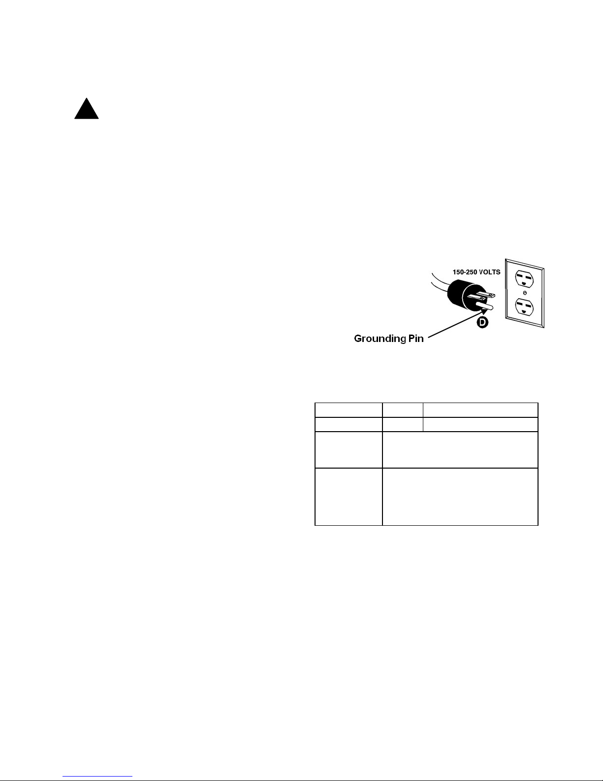
2. Grounded, cord-connected tools intended for
use on a supply circuit having a nominal rating
between 150-250 volts, inclusive:
This tool is intended for use on a circuit that has
an outlet that looks like the one illustrated in
Sketch D Fig. 12. The tool has a grounding plug
that looks like the plug illustrated in Sketch D.
Make sure the tool is connected to an outlet
having the same configuration as the plug. No
adapter is available or should be used with this
tool. If the tool must be reconnected for use on a
different type of electric circuit, the reconnection
should be made by qualified service personnel
and after reconnection, the tool should comply
with all local codes and ordinances.
Extension Cords
Use proper extension cord. Make sure your
extension cord is in good condition. When using
an extension cord, be sure to use one heavy
enough to carry the current your product will
draw. An undersized cord will cause a drop in
line voltage resulting in loss of power and
overheating. Fig. 13 shows the correct size to
use depending on cord length and nameplate
ampere rating. If in doubt, use the next heavier
gauge. The smaller the gauge number, the
heavier the cord
FIG. 12
Ampere Rating
Volts Total length of cord in feet
Ampere Rating
230 25' 50' 100'
150'
More Not
Than
More
Than
AWG
0 6
6 10
10 12
12 16
18 16 16 14
18 16 14 12
16 16 14 12
14 12
Not recommended
FIG. 13
Note: The reconnection shall be made by qualified
service personnel.
!

8
Adjustments
Warning: Always disconnect the machine from
the power source before making any
adjustments.
Failure to heed this warning can lead to serious
personal injury.
To adjust outfeed table
The outfeed table should be set level with the
highest point of the knives, Fig. 14. The height
of the outfeed table should be verified and
adjusted prior to first use. It should also be
verified and readjusted periodically to
compensate for knife wear and also upon knife
replacement.
The Jointer table is adjusted at manufactory and
should no further adjustment required. To align
the tip of knife & outfeed table as below if
necessary.
1. Make sure that the machine is
disconnected from the power source.
2. To give yourself unimpeded access to the
cutterhead and upper pulley, remove the
blade guard.
3. Set a straightedge (A, Fig. 14 & 15) onto
the outfeed table so that it sits over the
cutterhead but does not completely cross
the gap between the tables and do not
touch the infeed table.
4. Turn the upper pulley by hand, until any
one of the knives is at its highest point.
5. Loosen the C AP screw (B, Fig. 16) by
8mm Hex. wrenc h .
6. Push up or down the height adjustment
handle (C, Fig. 16) to adjust the outfeed
table height so th at the knife tip barely
touches the straight-edge
.
7. Re-tighten t he CA P scre w (B) to secure the
outfeed table in positio n.
8. If the outfeed table couldn’t low to correct
position release the Hex. nut (D) then loosen
the Hex. bolt (E), Fig. 17.
9. Lower the outfeed table to the location of the
appropriate by height adjustment h andle (C)
then tighten the CAP screw (B).
10. Re-tighten the Hex. nut (D)
11. Re-tighten the Hex. bolt (E).
FIG. 14
FIG. 15
FIG. 16
FIG. 17
A
OUTFEED
TABLE
INFEED
TABLE
(
RIGHT
)
A
B
C
B
D
E
 Loading...