

Page 1
Plug-In Switch Module
[Mx-EPSM]
Planning
Take a moment to plan and install the module for user convenience and optimal communi-
cation with other system components.
• Consider where the device will be plugged in, what it will control, and how power cords
can be kept out of the way
• Consider the construction materials in the space and obstacles that may interfere with
RF signals
Installing
Warning: ELECTRCAL SHOCK HAZARD. Do not open, cut the cord, or rewire the device.
Serious injury or death could result.
Proudly Made
In America
Package Contents:
- Plug-in Switch Module
Tools Required:
- None
Product Description:
The Magnum Plug-In Switch Module provides an easy way to save energy and control
lighting and appliance loads based on room occupancy.
The module simply plugs into any standard wall receptacle and receives wireless signals
from Magnum compatible products that tell it when to power on or o.
Features Include:
• Provides switching of plug-in electrical loads
• Communicates with other Magnum devices to enable energy savings
• Plugs into any standard outlet, no wiring required (optional mounting plate provided)
• Easily links with wireless rocker pads or sensors or connects to simple corded accessory
rocker pad
SPECIFICATIONS
Part Numbers
(Frequency Dependant)
Power Supply
Maximum Load or Contact
Ratings
Power Consumption
Transmission Range
Module Dimensions
Cord Lengths
Weight
Environment
Agency Compliance
M9-EPSM (902 MHz - North America)
M8-EPSM (868 MHz - Europe and China)
MJ-EPSM (928 MHz - Japan)
120 VAC 50/60Hz
General purpose: 15A@ 120VAC
Resistive: 15A 120VAC
Motor: ½ HP @ 120VAC
Tungsten: 960W @120VAC
Ballast: 600W @ 120 VAC
1.1W full load, 500mW quiescent
80ft (25m)
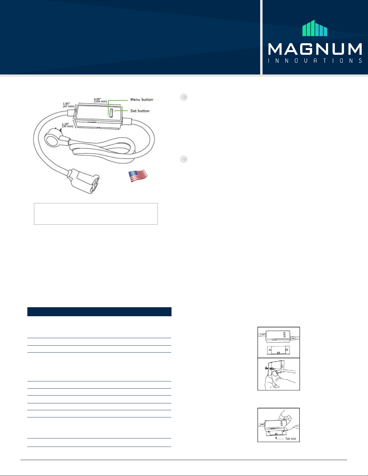
4.09” L x 1.85” W x 1.26” D
Plug cord: 3 ft. Outlet cord: 1 ft.
12.3 oz. (348 g)
• Indoor use only
• 32° to 104°F (0° to 44°C)
• 20% to 95% relative humidity (non-condensing)
cULus, FCC, and I.C.
Magnum Innovations
5675 Hudson Industrial Pkwy, Suite 3 - Hudson, OH 44236 - phone 330.915.2382 - fax 330.529.5279 - www.magnum-innovations.com - info@magnum-innovations.com
1. Turn the electrical load on (for example, a lamp) and unplug the cord from the wall
outlet.
2. Plug the cord of the electrical load, for example a lamp, into the outlet cord of the
module.
3. Plug the module into a standard wall outlet.
4. Test the connection by actuating the load using the Set button ( ) on the module.
Note: The plug and outlet are polarized, and not intended to be
mated with unpolarized devices.
Optional Mounting
The Plug-In Switch Module provides a fixed mounting option to prevent damage and theft.
Using the included mounting plate, mount the device high enough o the floor to avoid
spills and impact with cleaning equipment.
1. Using a level and a pencil, lightly mark two small dots to align the upper edge of the
module on the wall where you want to mount it.
Tip: For easy housekeeping, provide sucient clearance for vacuum cleaners.
2. Slide the mounting plate o the back of the module.
3. With the tab lock side down, mount the plate securely to the wall.
a. Using the pencil marks to
ensure it’s level, mark the
two mounting screw drill
points.
b. Drill two holes for the wall
anchors with a 3/16” drill
bit and insert the wall
anchors.
c. Insert the first screw
loosely and level the module.
d. Insert the second screw, and then hand tighten the first screw.
4. Slide the module onto the
mounting plate until it clicks in place.
Note: Any of the Magnum rocker
pads can be linked to the module.
For aordable remote control,
consider the Magnum Corded Accessory Rocker Pad (soldseparately).
Page 2
Plug-In Switch Module
[Mx-EPSM]
Linking
Magnum wireless systems are highly flexible; two or more compatible devices can be
linked and configured to provide the desired control.
There are two basic types of devices in the Magnum system; transmitters and
transceivers.
• Transmitters are simple energy-harvesting devices that send RF messages to communi-
cate a condition, level, or state. Transmitters can only be linked to transceivers.
• Transceivers are wire-powered controlling devices that send as well as receive RF
messages. They also process relevant control logic, and actuate the appropriate outputs
(switching a light on or o for example). Transceivers can be linked to transmitters as well
as other transceivers. A Magnum transceiver can have up to 30 devices linked to it.
The Plug-In Switch Module is a Transceiver
To link devices, the transceiver must first be powered, within the transmission range,
and set to accepts links using the setup interface on the transceiver. Next, the desired
transmitter, or another transceiver, is triggered to send a special link message. The
awaiting transceiver receives and stores the link permanently so the devices can interact
to provide a variety of intelligent control options.
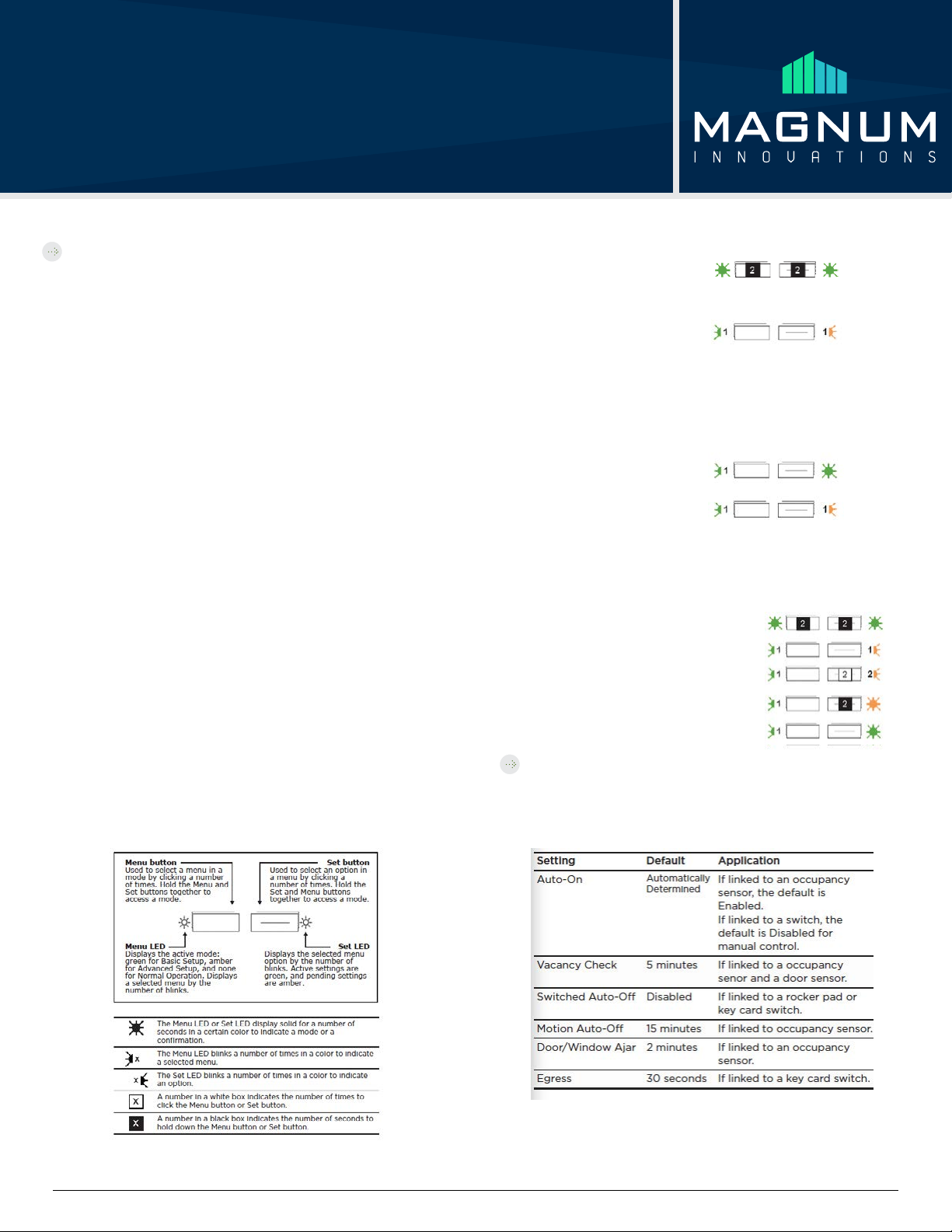
About the Setup Interface
The setup interface has two buttons, Menu and Set, that each have a corresponding
3-color LED (green, amber, red). This simple interface is used to link and configure
devices as a system.
The buttons and LEDs are used to navigate and select linking and setup options through a
3-tier menu system consisting of dierent Modes > Menus > Options. The LEDs respond
by showing solid or blinking lights of dierent colors to indicate active options and pend-
ing changes. To use the interface, hold the module so both thumbs can click the buttons
without obscuring the LEDs. The illustration and legend below describe how the buttons
are used and the meaning of the LED responses.
Tip: To exit and start over from anywhere in a menu, click both buttons at the same time
once.
To link a transmitter to a transceiver:
1. Access Basic Setup mode.
Note: By default, the Accept Link option in the Linking menu is selected. Once activated,
this option stays active for two minutes to provide time to link multiple devices.
Ready to accept links.
2. On the transmitter to be linked, do one of the following according to the type of device:
• Sensor: click the designated link button.
• Key Card Switch: insert/remove the card 3 times quickly.
• Rocker Pad: click the top button 3 times quickly.
Device linked successfully.
Set LED displays solid
green for 3 seconds.
Ready to accept new links.
3. To exit to normal operation, hold both buttons for 1 second.
To link a transceiver to another transceiver:
When two transceivers are linked to share system activity events, either one of them can
be used to send the link signal.
1. Access Basic Setup mode on both devices.
Ready to accept links.
2. On one of the devices, select the Send Link option.
3. Send a link signal from that device.
Devices linked successfully.
Configuring
The default settings on the module support common control and installation scenarios.
However, some settings can be adjusted on the module using the setup interface, if
required.
Magnum Innovations
5675 Hudson Industrial Pkwy, Suite 3 - Hudson, OH 44236 - phone 330.915.2382 - fax 330.529.5279 - www.magnum-innovations.com - info@magnum-innovations.com
Page 3

Plug-In Switch Module
[Mx-EPSM]
Auto-On
The default Auto-On option is automatically determined based on the type of device that
is linked. Auto-On is Disabled if the first linked device is a switch, or Enabled if the device
is an occupancy sensor.
From the Auto-On menu, the
active option is indicated by
the number of green blinks on
the Set LED; amber blinks
indicate an unsaved change.
Click the Set button an
appropriate number of times
to select an option.
To change the auto-on option:
This example shows changing the option from Automatically
Determined to Disabled.
1. Access Basic Setup mode.
2. Access the Auto-On menu.
3. Select an option.
4. Save the selection.
Vacancy Check
The vacancy check is a time delay that is activated when a door
opens and closes. The linked loads will turn o, if the sensor(s)
do not confirm occupancy
within the time delay.
From the Vacancy Check menu,
the active option is indicated by
the number of green blinks on
the Set LED; amber blinks
indicate an unsaved change.
Click the Set button an appropriate number of times to select an option.
To change the vacancy check option:
This example shows changing the option from 5 to 15 minutes.
1. Access Basic Setup mode.
2. Select the Vacancy Check
menu.
3. Select an option.
4. Save the selection.
Auto-O
There are two auto-o menus, one for occupancy sensors, and one for switched devices.
For linked occupancy sensors, the default is 15 minutes. For linked rocker pads and key
card switches, the default is Disabled to allow manual control.
From the auto-o timer menu,
the active option is indicated
by the number of green blinks
on the Set LED; amber blinks
indicate an unsaved change.
Click the Set button an
appropriate number of times
to select an option.
To change the switched auto-o option:
This example shows changing the option from Disabled to 5 minutes.
1. Access Basic Setup mode.
2. Select the Switched Auto- O menu.
3. Select an option.
4. Save the selection.
To change the motion auto-o option:
This example shows changing the option from 15 minutes to 5
minutes.
1. Access Basic Setup mode.
2. Select the Motion Auto-O menu.
3. Select an option.
4. Save the selection.
Magnum Innovations
5675 Hudson Industrial Pkwy, Suite 3 - Hudson, OH 44236 - phone 330.915.2382 - fax 330.529.5279 - www.magnum-innovations.com - info@magnum-innovations.com
Page 4

Plug-In Switch Module
[Mx-EPSM]
Trouble Shooting
The device does not power up.
• Check the wiring for errors.
• Check the circuit breaker.
• Use a voltage meter to confirm power.
• Verify the cord is not plugged into a switched outlet.
The decive does not control linked load.
Cannot link other devices.
Cannot change settings on the device.
The device does not respond to wireless
messages or selected settings.
• Click the Set button to open/close the relay.
• Turn o the power and then restore it.
• Check if Accept Link option can be accessed.
• Move vloser to the device; it may be out of range.
• Try linking a dierent device.
• Check for environmental conditions that interfere.
• Verify the max. number of devices (30) has not
been exceeded.
• Check if menu item can be accessed.
• Check if changes can be saved.
• Check for environment range issues.
• Verify the device is linked.
• Check if the appropriate devices are linked
accordingly to good system planning.
FCC SZV-STM300C
I.C. 5713A-STM300C
This device complies with Part 15 of the FCC Rules. Operation is subject to the following two
conditions: (1) this device may not cause harmful interference, and (2) this device must accept any
interference received, including interference that may cause undesired operation.
Magnum Innovations
5675 Hudson Industrial Pkwy, Suite 3 - Hudson, OH 44236 - phone 330.915.2382 - fax 330.529.5279 - www.magnum-innovations.com - info@magnum-innovations.com
 Loading...