

Magnum Ruutu L 6.0kW, Ruutu C 6.0kW, Ruutu L 6.6kW, Ruutu L 9.0kW, Rutuu C 9.0kW Operating Instructions Manual
...Page 1
Operating instructions
Magnum Ruutu L 6.0kW - 6.6kW - 9.0kW - 10.5kW
Magnum Ruutu C 6.0kW - 9.0kW
Magnum Klubi 6.0kW - 9.0kW
Page 2

2
Magnum Kiuas – Operating and installation instructions 03.04.2019
Starsauna Oy Technical Support:
Pistotie 4 +358405455625 (from 8-16)
15860 Hollola, Finland info@magnumkiuas.fi
These instructions are intended for the owner of the sauna or the person
responsible for its maintenance, as well as for the electrician who installs the
sauna stove. The electrician will give these instructions to the owner of the
sauna or the person responsible for its maintenance after the stove has been
installed successfully. The owner of the sauna stove or the person responsible for
its maintenance must store these instructions for the entire lifespan of the sauna
stove, because changes may be made to the components. Keeping the original
instructions ensures that the circuit diagrams and the connection methods used
during maintenance works are intended for this particular sauna stove.
The owner of the sauna must read these instructions carefully before first
using the sauna stove. The instructions contain full operating and maintenance
instructions, installation instructions, a troubleshooting guide and the warranty
terms for the sauna stove and its parts.
The electrician must ensure that the device has been disconnected from the
power supply before performing any installation or maintenance work. The
fitter should avoid touching the internal components and integrated circuits of the
device unnecessarily. Touching can result in a discharge of static electricity,
which may damage the device or one of its electrical components. The electrician
must ensure that the device is grounded correctly and that all connections have
been completed according to the instructions.
The only purpose of this sauna stove is to heat the sauna to a suitable sauna
temperature. The sauna stove must not be used for any other purpose. The
sauna stove must never be covered, and the person using the sauna should always
check the sauna stove before heating it, to ensure that there is nothing flammable
or anything that does not belong to a sauna either on top or beside the sauna
stove.
Page 3
3
Magnum Kiuas – Operating and installation instructions 03.04.2019
Starsauna Oy Technical Support:
Pistotie 4 +358405455625 (from 8-16)
15860 Hollola, Finland info@magnumkiuas.fi
TABLE OF CONTENTS
1. Using the device – Finlandia Control Centre ............................................................................................................ 4
1.1 – Control Functions – Finlandia Control Centre ..................................................................................................... 4
1.2 – Menu structure – Finlandia Control Center ......................................................................................................... 5
2. Using the sauna stove ................................................................................................................................................ 5
2.1 – Adjustable settings ............................................................................................................................................... 5
...................................................................................................................................................................................... 5
2.2 – target temperature ................................................................................................................................................ 5
2.3 – Heating time ......................................................................................................................................................... 6
2.4 - Timer .................................................................................................................................................................... 6
2.5 – Turning the sauna off ........................................................................................................................................... 6
2.6 – Directions for using the sauna .............................................................................................................................. 7
3. Installation of the sauna stove ................................................................................................................................... 8
3.1 – Installation stages ................................................................................................................................................. 9
3.2 – Thermostat sensor .............................................................................................................................................. 13
3.3 - Finlandia control panel ................................................................................................................................. 14
Surface Installation: .................................................................................................................................................... 14
Recessed mount: ......................................................................................................................................................... 15
4. Installation illustrations and renderings .................................................................................................................. 16
4.1- Thermostat and controller – Installation in the sauna .......................................................................................... 16
4.2- Mechanical ventilation......................................................................................................................................... 17
4.3 - Natural gravitational ventilation ................................................................................................................... 18
4.4 - Piling stones in the sauna stove .................................................................................................................... 19
4.4.1 Stone piling stages Ruutu L: ....................................................................................................................... 19
4.4.2 - Stone piling stages Klubi and Ruutu C: ................................................................................................... 20
4.5 -Sauna stove wall bracket ............................................................................................................................... 21
5. Technical information and safety distances of the sauna stoves ............................................................................. 22
5.1 – Illustration of safety distances ............................................................................................................................ 22
5.2 -Physical measurements and technical specifications of the sauna stoves ...................................................... 23
6. Warranty ................................................................................................................................................................. 25
7. Connection diagram ................................................................................................................................................ 26
8. Sauna stove care and maintenance .......................................................................................................................... 27
9. Problems/troubleshooting guide ............................................................................................................................. 28
Page 4
4
Magnum Kiuas – Operating and installation instructions 03.04.2019
Starsauna Oy Technical Support:
Pistotie 4 +358405455625 (from 8-16)
15860 Hollola, Finland info@magnumkiuas.fi
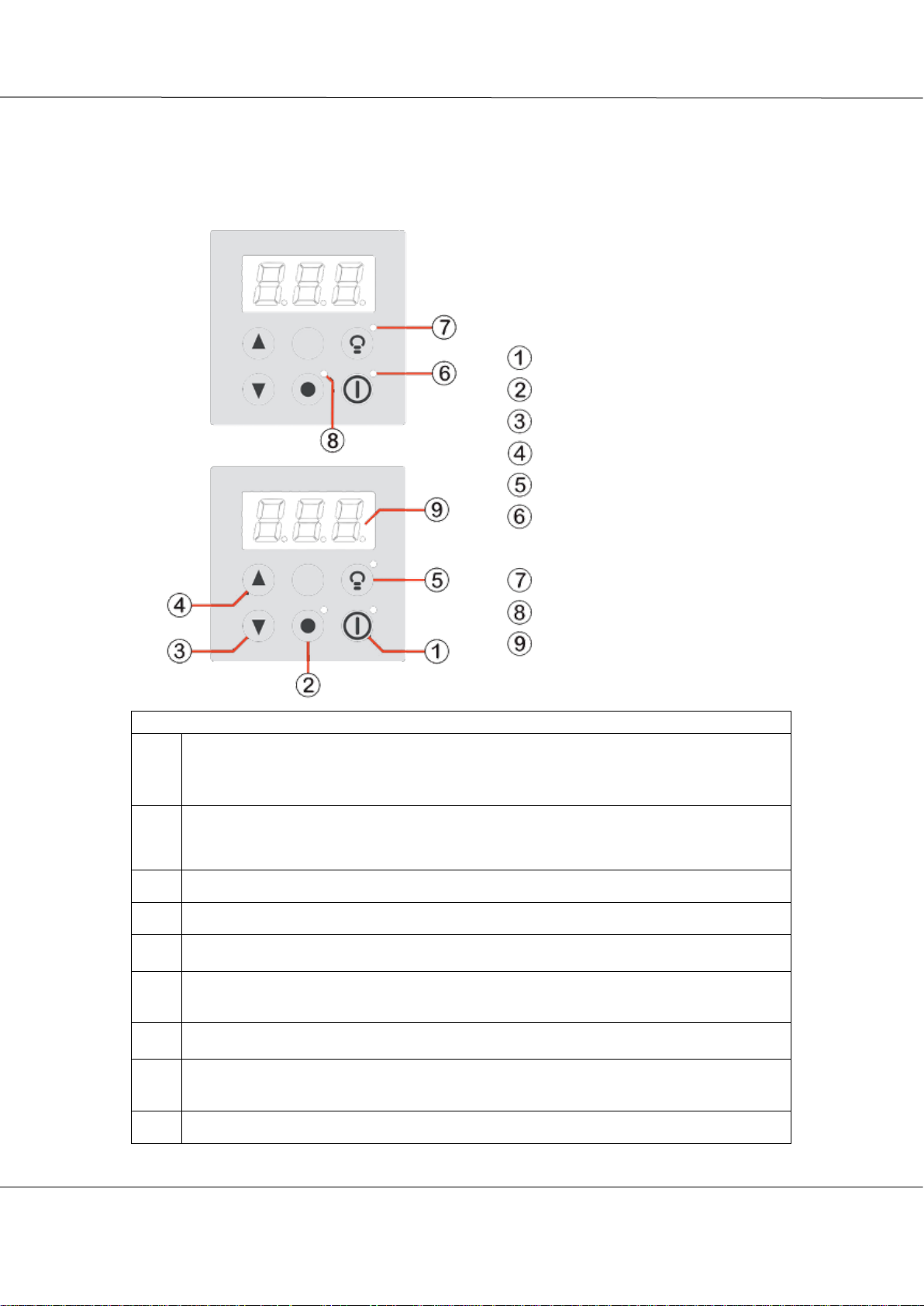
1. USING THE DEVICE – FINLANDIA CONTROL CENTRE
1.1 – CONTROL FUNCTIONS – FINLANDIA CONTROL CENTRE
Sauna stove On/Off
Menu/Selection button
Decrease
Increase
Light control
The heating/timing indicator light
Sauna stove light’s indicator light
Menu settings indicator light
Number display
Legend for the parts of the control panel:
1.
On/Off button. Pressing this button turns the sauna stove on and off. If the timer has been set,
pressing this button starts the timer for heating the sauna.
Tip: Pressing this button for a longer duration overrides the timer and starts the heating
of the sauna stove immediately.
2.
Menu button: by pressing this, you can move through the menus of the device as follows:
(Default mode –> Target temperature –> Heating time –> Timer –> Default mode)
3.
(˅) button. This button is used to decrease the default values.
4.
(˄) button. This button is used to increase the default values.
5.
Lights button: by pressing this, you can turn on the sauna stove’s light. Pressing it again turns
the light off. (Only used in models with lights or a separate fibre kit)
6.
“Device on” indicator light. This light is constantly on while the sauna stove is on. The light
”glows” when the timer is in use. The light is turned off when the sauna stove is not on.
7.
Sauna stove light’s indicator light. This light is on as an indicator of the fibre light kit of the
sauna stove / sauna being on.
8.
Menu settings indicator light. This light comes on when a menu setting is adjusted. (timer,
the time the device is on, the target temperature of the sauna stove)
9.
Three-digit display
Page 5
5
Magnum Kiuas – Operating and installation instructions 03.04.2019
Starsauna Oy Technical Support:
Pistotie 4 +358405455625 (from 8-16)
15860 Hollola, Finland info@magnumkiuas.fi
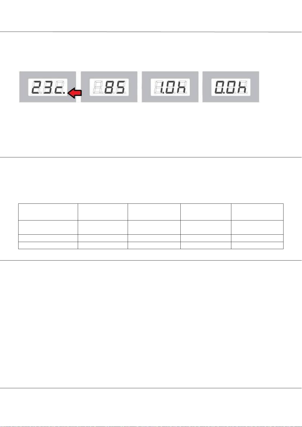
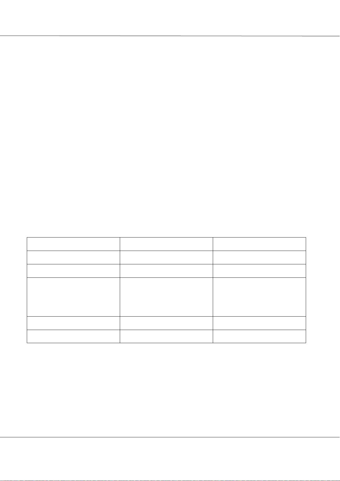
1.2 – MENU STRUCTURE – FINLANDIA CONTROL CENTER
Default status (temperature display) Target temperature Heating time Timer
The adjustment menus of the device are shown in the image above. The user can move from one menu to
another using the Menu button. When the sauna stove is on, the (˄) and (˅) buttons can be used to adjust the
settings, as shown in the image above. The dot in the lower right corner will be on when the resistors warm
up (indicated with an arrow).
2. USING THE SAUNA STOVE
2.1 – ADJUSTABLE SETTINGS
Parameter
Adjustment
range
Adjustment
increment
Default value
Please note!
Target temperature
adjustment
40-110°C
1°C
60°C
Heating time
1 h - 6 h
0.5 h
1 h
See Section 2.3
Timer
0.5 – 24 h
0.5 h
0 h
Not in use
2.2 – TARGET TEMPERATURE
The sauna’s target temperature may be adjusted in increments of one Celsius. The minimum temperature is 40 degrees
and the maximum temperature is 110 degrees. This setting is saved.
The target temperature can be adjusted in two different ways.
1. Pressing the Menu button shows the target temperature on the screen.
You can use the +/˄ and –/˅ buttons to change the value. If you do not press any buttons, the
controller will stop displaying the target temperature menu automatically in approx. 10 seconds. You
can also exit the menu by pressing the Menu button repeatedly.
2. When the sauna temperature is on the display, pressing the (+/˄) or (–/˅) button causes the controller
to move directly to the target temperature settings. Exiting the menu happens as described in section 1.
Page 6
6
Magnum Kiuas – Operating and installation instructions 03.04.2019
Starsauna Oy Technical Support:
Pistotie 4 +358405455625 (from 8-16)
15860 Hollola, Finland info@magnumkiuas.fi
2.3 – HEATING TIME
You can set the sauna stove’s heating time to be between 1 h and 6 h. The adjustment takes place in increments of 0.5
h. The time value has to be set when the device is turned off. You can move to this setting from the default move by
pressing the Menu button twice.
It is possible to reduce the time the stove is on when the sauna is heating. You can increase or decrease the time of the
sauna session by pressing the (+/˄) or (–/˅) button when the remaining time is on the display. In this case, the
adjustment increment is 15 min. This setting is not saved to the memory. This setting can also be changed by pressing
the Menu button twice in default mode.
2.4 - TIMER
You can move from the default mode to the timer by pressing the Menu button three times in a row. The (+/˄) and (–
/˅) buttons are used to change the timer’s setting. The adjustment range is 0.5 h – 24 h, and the adjustment increment
is 0.5 h. If this value is zero, the timer is not in use.
This setting can only be changed when the device is off.
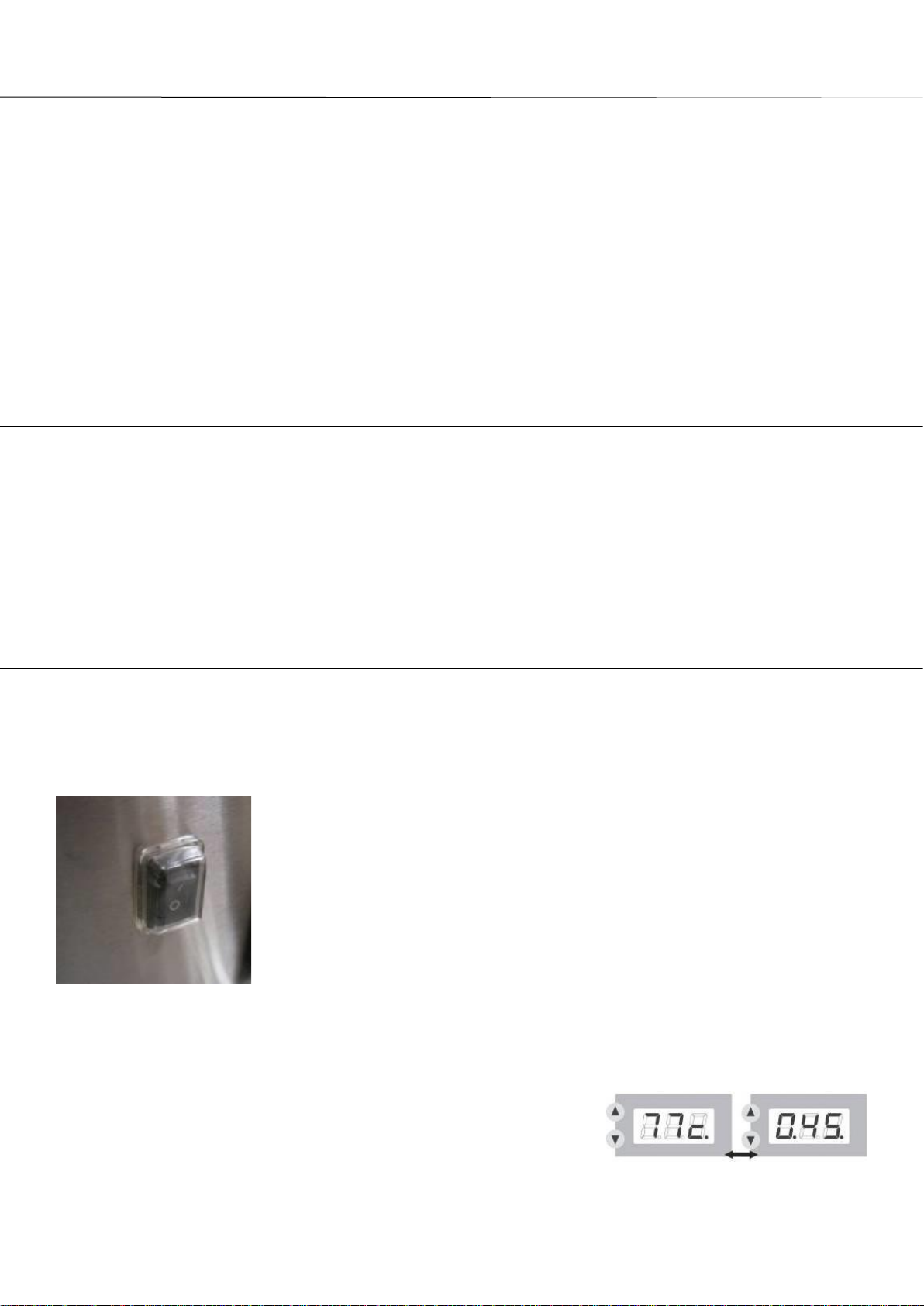
2.5 – TURNING THE SAUNA OFF
Turn the sauna stove’s power on using the control switch at the lower part of the sauna
stove. Make sure that the sauna stove is not covered, and that there is nothing in the sauna
that does not belong there. Pressing the Controller’s On/Off button makes the sauna stove
start heating until the target temperature has been reached. The stove heating indicator
light in the controller will switch on. The decimal mark lights up on the lower right side
of the screen to indicate that the resistors are on. (If the timer has been set, the On/Off
button turns the timer on and the sauna stove begins heating only after the timer has run
out). The On/Off button turns the sauna stove off.
Tip: If the timer has been set but the sauna stove is not on, you can override the timer by pressing
the On/Off button and keeping it pressed for a few seconds. This causes the stove to
start heating up immediately. The timer’s setting nevertheless remains in the device
memory.
When the device is on, the default mode (temperature) and the remaining time
alternate on the display. The alternation interval is approx. 10 seconds.
1- CONTROL SWITCH
Page 7
7
Magnum Kiuas – Operating and installation instructions 03.04.2019
Starsauna Oy Technical Support:
Pistotie 4 +358405455625 (from 8-16)
15860 Hollola, Finland info@magnumkiuas.fi
2.6 – DIRECTIONS FOR USING THE SAUNA
• Heat the sauna stove once before first use, as the protective substances in the new stones may give off odours while
the sauna stove is heating. Ensure there is sufficient ventilation After the heating is completed, open the sauna
window (if applicable).
• Make sure that the sauna stove has not been covered, and that there is nothing in the sauna that does not belong
there (laundry, children’s toys, etc.)
• The recommended temperature if 55 – 70 degrees.
• The sauna stove heats to a suitable sauna temperature in approx. 25 – 80 minutes, depending on the size of the sauna
stove, the size of the sauna, and the ventilation.
• User water that is suitable for domestic use when throwing water on the sauna stove. The use of seawater is
forbidden.
• Do not throw water on the sauna stove if there are people next to it, as the water splashing from the sauna stove and
the steam it creates are scalding hot.
• Move carefully in the sauna, as the floors may be slippery.
• The manufacturer recommends heating the sauna stove until hot, and turning it off at the beginning of the sauna
session. It will spare the resistors considerably if cold water is not thrown on a resistor glowing red-hot. The mass
of stones will keep the sauna hot for a long time, and “once-off heating” enables to have a sauna session of about
20 – 30 min before the sauna stove has to be switched on again.
Quality requirements for the heating water
Water condition:
Effect:
Recommendation:
Water containing humus
Colour, taste, deposits
<12 mg/l
Water containing iron
Colour, odour, taste, deposits
<0.2 mg/l
Hardness: the most important
substances are manganese
(Mn) and chalk or calcium
(Ca)
Deposits
Mn: <0.05 mg/l
Ca: <100 mg/l
Water containing chloride
Health risk
Use is banned
Seawater
Fast corrosion
Use is banned
Page 8
8
Magnum Kiuas – Operating and installation instructions 03.04.2019
Starsauna Oy Technical Support:
Pistotie 4 +358405455625 (from 8-16)
15860 Hollola, Finland info@magnumkiuas.fi
3. INSTALLATION OF THE SAUNA STOVE
• The electrical installation may only be performed by a qualified electrician
• Instructions for the electrical installation are provided in the circuit
diagram in these installation instructions as well as on the sticker on the
sauna stove.
• The electrical installation work may only be performed by an electrician
qualified for the job, in accordance with applicable regulations.
• The sauna stove is connected to the power grid semi-permanently with H07RN-
F or similar rubber cable.
• Check the required cable dimensions in the table below.
• Please note! The use of a PVC cable as a connection cable is not permitted.
• The power switch in the device is a so-called control switch, and it does not
fully de-energise the sauna stove.
Sauna stove
POWER
FUSE
FEED CABLE
SAUNA SIZE
Magnum 6 – 6.6
6.6 KW
3x10 A
5x1.5 mm2
5-9 m3
Magnum 9
9 KW
3x16 A
5x2.5 mm2
8-15 m3
Magnum 10.5
10.5 KW
3x16 A
5x2.5 mm2
10-20 m3
Page 9
9
Magnum Kiuas – Operating and installation instructions 03.04.2019
Starsauna Oy Technical Support:
Pistotie 4 +358405455625 (from 8-16)
15860 Hollola, Finland info@magnumkiuas.fi
3.1 – INSTALLATION STAGES
1. Remove the stainless steel frame from the upper part of the sauna stove.
2. Remove the protective plastics from the metal parts.
3. Fold the sauna stove’s cardboard box up and set the sauna stove on its side on the cardboard. Ensure that the sauna
stove does not become scratched.
4. Open the hatch at the base of the sauna stove.
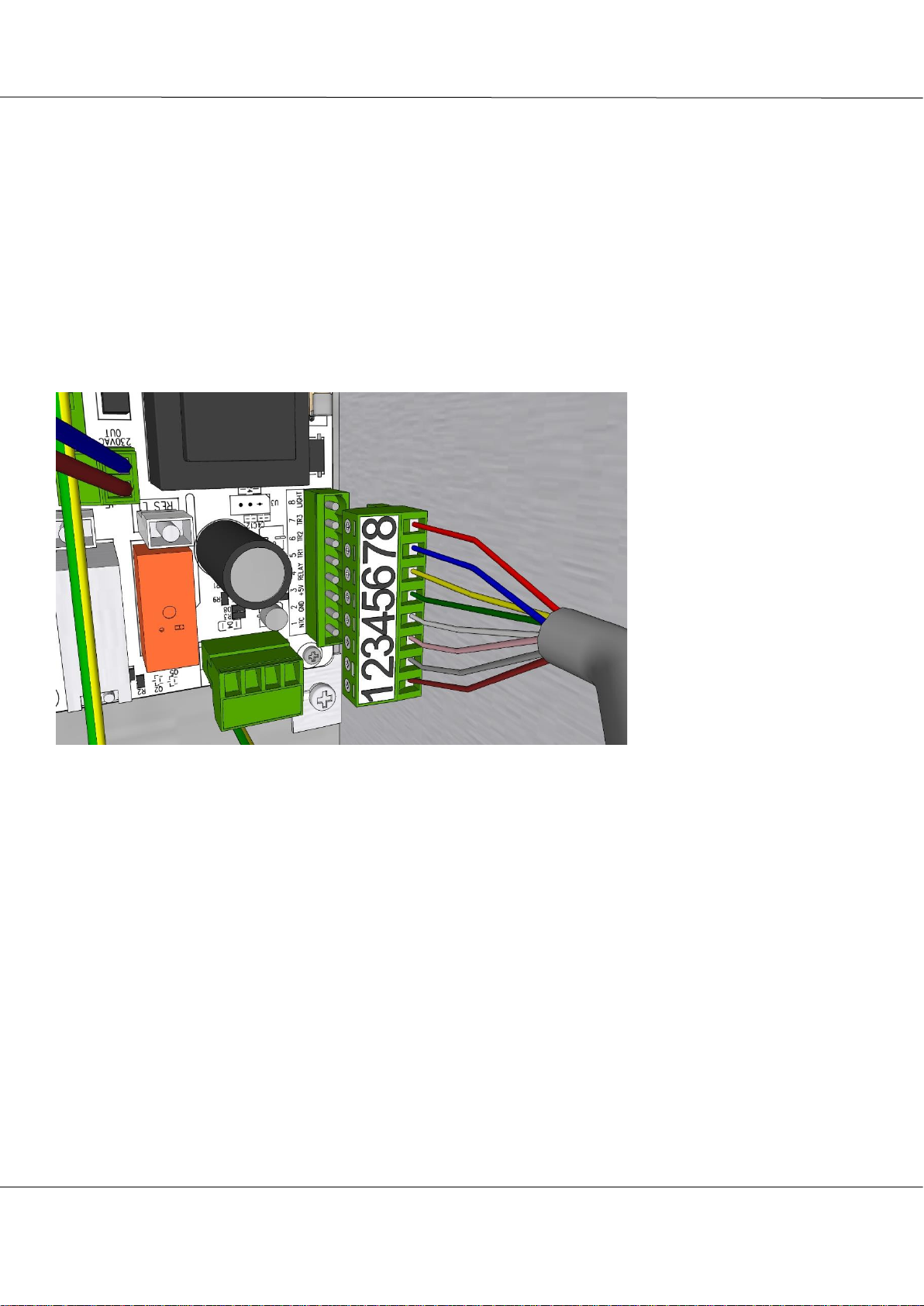
5. Feed the Finlandia panel wire (8x0.25 mm2 LYII grey cable) through the lowest cable gland and connect the wires
on the circuit board on the terminal block with the numbers 1-8. The terminal block can be detached from the
main board for easier installation. The terminal block is located in the lower left section. Tighten the cable gland
after the installation is complete.
Order of wires on the board
1. Brown
2. Grey
3. Pink
4. White
5. Green
6. Yellow
7. Blue
8. Red
6. Connect the thermostat sensor according to SECTION 3.2. Feed the thermostat sensor wire (4x0.25 mm2 silicone
cable, beige wire) through the second-lowest cable gland and connect the wires on the circuit board, to the 4-slot
terminal block adjacent to the Finlandia panel block. The terminal block can be detached from the main board for
easier installation. Tighten the cable gland after the installation is complete.
Page 10

10
Magnum Kiuas – Operating and installation instructions 03.04.2019
Starsauna Oy Technical Support:
Pistotie 4 +358405455625 (from 8-16)
15860 Hollola, Finland info@magnumkiuas.fi
The wire order on the board,
from right to left.
1.Blue
2.White
3.Red
4.Yellow
PLEASE NOTE! If the wire
needs to be shortened, shorten
it from the stove’s side. The
wire must not be continued.
Page 11

11
Magnum Kiuas – Operating and installation instructions 03.04.2019
Starsauna Oy Technical Support:
Pistotie 4 +358405455625 (from 8-16)
15860 Hollola, Finland info@magnumkiuas.fi
7. Feed the supply cable through the upmost cable gland and connect the feeder line to the quick connector on the
circuit board. Wires with glands can be pressed directly into the connector, otherwise, the spring lever might have
to be loosened. Tighten the cable gland after the installation is complete. From left to right: N, L3, L2, L1,
Ground, Ground. The texts on the board are upside down when viewed from the bottom of the sauna stove.
8. Temperature reduction (Connector J5) (the lower connector on the photo above). If this feature is in use, it is
possible to connect a relay or contactor coil to the output, which controls the heating of the building. It is
recommended to use a seven-stranded cable for wiring the sauna stove. Detach the connector from the circuit
board and screw the cables to the connector. Then, press the connector back onto the circuit board.
• N – 230VAC OUT – Blue above
• P – External – Brown below
9. If the sauna stove is intended to power sauna lamps as well, install the cable gland M20/10 (e.g. e-number
1704106). The lights connector is located in the middle left. The maximum strength of lamps is 100W/0.5A
• P – External – Brown above
• N – 230VAC – Blue below
Page 12

12
Magnum Kiuas – Operating and installation instructions 03.04.2019
Starsauna Oy Technical Support:
Pistotie 4 +358405455625 (from 8-16)
15860 Hollola, Finland info@magnumkiuas.fi
10. Close the hatch on the base of the sauna stove.
11. Install the Finlandia control panel in accordance with CHAPTER 3.3. Wiring instructions for the panel below.
From left to right, viewed from
behind:
8. Pink
7. Grey
6. Red
5. Yellow
4. Green
3. White
2. Brown
1. Blue
The panel wiring is not
identical to the control centre
wiring, because we wish to keep
the product compatible with
old systems.
It is not recommended to
shorten wires from the panel’s
side, as the wires have been
fitted with quick connectors. If
necessary, shorten the wires
from the centre’s side.
12. Feed the other end of the supply cable to the electrical box. Please note that the maximum height of the junction
box is 400 mm
13. Put the control switch into position I
14. Test resistor functionality by turning the sauna stove on. If all the resistors do not heat or if there is another issue,
contact the retailer or technical support.
15. Install the lower part of the sauna stove, taking the safety distances into consideration. Adjust vertically, using the
adjustment feet.
16. Pile the stones in the sauna stove in accordance with CHAPTER 4.4.
17. The sauna stove must be heated once before people use it for the first time, and the sauna must be thoroughly
ventilated afterwards. There may be impurities in the stones, and some residue of storage/machining lubricants on
the sauna stove, the traces of which will disappear during the first heating. Also monitor the settling of the stones
after the first heating, and add more stones on top, if necessary.
Page 13

13
Magnum Kiuas – Operating and installation instructions 03.04.2019
Starsauna Oy Technical Support:
Pistotie 4 +358405455625 (from 8-16)
15860 Hollola, Finland info@magnumkiuas.fi
3.2 – THERMOSTAT SENSOR
THERMOSTAT SENSOR
CONNECTING THE WIRES
The thermostat sensor is wooden, its external casing is
made from black alder.
The external casing can be painted to match the sauna
panels using sauna wax, but remember to detach all
electronic components from the sensor before painting.
Electronic components could be damaged by paint.
Connect the connector to the designated connector on the
circuit board, press the connector carefully all the way down.
Thermostat sensor are installed on the wall so that the distance between the ceiling and the upper edge of the
sensor is 100 mm. The sensor must be located 500 – 1000 mm from the upper edge of the sauna stove.
Furthermore, the sensor must be located at least 1000 mm from a non-directed incoming air valve or 500
mm from an incoming air valve which is located away from the device. Illustration SECTION 4.1
Install the thermostat cable behind the panel in the air vent; if this is not
possible, use an installation baseboard. Make sure that the incoming air does not
disturb the heat sensor.
Do NOT cut the wire from the thermostat’s side. The thermostat sensor does
not function if the wires are continued/reconnected. If the wire needs to be
shortened, shorten it from the connector’s side. In other cases, contact the
technical support.
To the
connector
Blue
White
Red
Yellow
To the
circuit
board
1 2 3
4
THERMOSTAT SENSOR WIRE AND CONNECTOR
Page 14

14
Magnum Kiuas – Operating and installation instructions 03.04.2019
Starsauna Oy Technical Support:
Pistotie 4 +358405455625 (from 8-16)
15860 Hollola, Finland info@magnumkiuas.fi
3.3 - FINLANDIA CONTROL PANEL
There are many installation options for the Finlandia control panel. The maximum height of the control panel from the floor of the
sauna or the washroom floor is 1000mm. The requirements of the electrical wiring standard SFS 6000, sections 7-701, are
applicable to the washroom. The ingress protection of the Finlandia panel is IPX4. The standard length of the control panel’s wire
is 10 metres.
SURFACE INSTALLATION:
In the sauna: Install the surface box at a max height of 1000mm from the floor, and bring the wire out of the box. Screw the
panel’s mounting bracket to the box. In the washroom: no height restrictions, but the recommended height is 1500mm or at the
same height as the light switches.
Place the frame on the bottom of the box, connect the wires to the panel, and press the control panel to fasten it in the middle of
the frame. The panel will be attached to the bracket with magnets. Wiring instructions on page 11.
Page 15

15
Magnum Kiuas – Operating and installation instructions 03.04.2019
Starsauna Oy Technical Support:
Pistotie 4 +358405455625 (from 8-16)
15860 Hollola, Finland info@magnumkiuas.fi
RECESSED MOUNT:
In the sauna: Drill a hole in the panel for the recess box. Be careful not to drill all the way to the insulation. The max height of
the panel from the sauna floor is 1000mm. Bring the panel wire out of the box. Screw the panel’s mounting rod t o the box. In the
washroom: no height restrictions, but the recommended height is 1500mm or at the same height as the light switches. When
installing on a tiled surface, recessed mounting has to be taken into consideration already during the construction stage. Suitable
box e.g. ABB AUS 15.2 “Renovation box”. Hole 70mm – Box drill AT1.
Place the frame on the bottom of the box, connect the wires to the panel, and press the control panel to fasten it in the
middle of the frame. The panel will be attached to the bracket with magnets. Wiring instructions on page 11.
The panel can be integrated into the light switches using a double frame. Any frame from the Schneider
Electric Exxact range can be used.
Page 16

16
Magnum Kiuas – Operating and installation instructions 03.04.2019
Starsauna Oy Technical Support:
Pistotie 4 +358405455625 (from 8-16)
15860 Hollola, Finland info@magnumkiuas.fi
4. INSTALLATION ILLUSTRATIONS AND RENDERINGS
4.1- THERMOSTAT AND CONTROLLER – INSTALLATION IN THE SAUNA
A. The distance of the thermostat from the outer edge of the sauna stove is 500 – 1000 mm. PAY ATTENTION TO THE
INCOMING AIR VALVE. If incoming air cannot be directed away from the thermostat, the valve may not be installed
less than 1000 mm from the incoming air valve If it can, the installation distance may be between 500 mm - 1000 mm.
B. The distance of the thermostat from the ceiling is 100 mm.
C. The minimum distance of the control panel from the sauna stove is 500 mm.
D. The maximum height of the control panel from the floor is 1000 mm.
Page 17

17
Magnum Kiuas – Operating and installation instructions 03.04.2019
Starsauna Oy Technical Support:
Pistotie 4 +358405455625 (from 8-16)
15860 Hollola, Finland info@magnumkiuas.fi
4.2- MECHANICAL VENTILATION
It is recommended that incoming air is directed straight on top of the sauna stove, so that fresh air can be distributed in
the steam room with the steam. Air should be replaced six times per hours.
A- Supply air
B- Exhaust air
Page 18

18
Magnum Kiuas – Operating and installation instructions 03.04.2019
Starsauna Oy Technical Support:
Pistotie 4 +358405455625 (from 8-16)
15860 Hollola, Finland info@magnumkiuas.fi
4.3 - NATURAL GRAVITATIONAL VENTILATION
With natural gravitational ventilation, the supply air should be either on the floor, or low on the wall next to the sauna
stove. The exhaust air can be on the wall or on the ceiling. The outlet valve should be closed during a sauna session, to
keep the heat in the sauna. The valve is opened after a sauna session, to let the sauna dry. Air can partially escape also
to the washroom, if there is a sufficiently large gap underneath the door.
A- Supply air
B- Exhaust air
Page 19

19
Magnum Kiuas – Operating and installation instructions 03.04.2019
Starsauna Oy Technical Support:
Pistotie 4 +358405455625 (from 8-16)
15860 Hollola, Finland info@magnumkiuas.fi
4.4 - PILING STONES IN THE SAUNA STOVE
Preparations:
1. Ensure that the sauna stove is correctly connected and that the resistors definitely heat up. Do not pile stones in the sauna stove if the
sauna stove does not work fully!
2. The benches should be installed before the stones are piled in the sauna stove, particularly if the sauna stove is integrated through the
benches.
3. Place the sauna stove in its intended location, considering the safety distances. Straighten the sauna stove, using the adjustment feet.
4. For the installation, you will need a spirit level, protective gloves, 70 - 150 kg of rocks with a diameter of 5 - 10 cm (depending on the
sauna stove model, see section 5.2), specifically rocks intended for use in the sauna stove, for example olivine diabase, olivine or
peridot. Wash the rocks, if necessary.
5. In the installation illustrations, the parts of the sauna stove have been rendered in different colours and transparent, to make the
instructions clearer.
4.4.1 STONE PILING STAGES RUUTU L:
1. Make sure the stones are not tumbled on the sauna stove bottom. Do not wedge the resistors. Ensure that the resistors remain vertical
throughout the entire stoning process. Do not pack the stones tightly. Ensure that there are stones also between the resistors.
2. If you have reached about 50mm above the bend in the middle of the resistors, drop the first resistor plate on top of the stones. This
plate will help the resistors stay upright, and prevent them from moving as the stones sink.
3. Continue piling stones in the sauna stove until you have reached about 60mm from the highest section of the lower part, and put the
upper part in its place.
4. Pile the sauna stove with stones until you have reached approx. 50mm below the highest point of the resistors.
5. Lower the upper resistor plate on the stones. This plate will help the resistors stay upright, and prevent them from moving as the stones
sink. If necessary, install the sauna stove’s wall brackets in accordance with SECTION 4.5.
6. Finish piling stones in the sauna stove. The stones on the top should be tightly packed. You should put large stones on top.
Page 20

20
Magnum Kiuas – Operating and installation instructions 03.04.2019
Starsauna Oy Technical Support:
Pistotie 4 +358405455625 (from 8-16)
15860 Hollola, Finland info@magnumkiuas.fi
4.4.2 - STONE PILING STAGES KLUBI AND RUUTU C:
1. Make sure the stones are not tumbled on the sauna stove bottom. Do not wedge the resistors. Ensure that the resistors
remain vertical throughout the entire stoning process. Do not pack the stones tightly. Ensure that there are stones also
between the resistors.
2. If you have reached about 50mm above the bend in the middle of the resistors, drop the first resistor plate on top of the
stones. This plate will help the resistors stay upright, and prevent them from moving as the stones sink.
3. Pile the sauna stove with stones until you have reached approx. 50mm below the highest point of the resistors.
4. Lower the upper resistor plate on the stones. This plate will help the resistors stay upright, and prevent them from moving
as the stones sink. If necessary, install the sauna stove’s wall brackets in accordance with SECTION 4.5.
5. Finish piling stones in the sauna stove. The stones on the top should be tightly packed. You should put large stones on
top.
When piling stones in the sauna stove, always ensure that the
resistors are straight. Resistors that are turning outwards can
be a fire hazard. Resistors that are turning inwards can
burn through prematurely. If necessary, attach the sauna
stove to the wall with the supporting brackets included in
the package. A sauna stove with too few stones is a fire
hazard! Covering the sauna stove is a fire hazard! The
uppermost layer of the stones must be as tight as
possible, the resistors must not be visible. We
recommend that the sauna stove stones are re-piled on a
yearly basis! Always replace burned and cracked stones
with new ones. If you use the sauna every day, it is
recommended that the stones are piled again every 3
mths. The use of ceramic stones other than (KERKES) is
forbidden. Other ceramic stones may cause the resistors
to break down prematurely.
Page 21

21
Magnum Kiuas – Operating and installation instructions 03.04.2019
Starsauna Oy Technical Support:
Pistotie 4 +358405455625 (from 8-16)
15860 Hollola, Finland info@magnumkiuas.fi
4.5 -SAUNA STOVE WALL BRACKET
The sauna stove can also be secured to a wall, using the wall brackets included in the package. The bracket is intended to be
mounted on the upper edge of the sauna stove, between the grid.
1. Test the fit of the brackets to the sauna stove/wall before attaching to the wall. The bracket is placed in the square hole on
the sauna stove.
2. Bend the brackets, if necessary PLEASE NOTE: if you are bending the brackets by hand, use protective gloves.
3. When the bracket seems to be positioned well, mark the attachment points on the wall.
4. Drill a small starting hole at the mark, so that the panel would not crack during the screwing process
5. Place the brackets to the hollows of the upper part of the sauna stove, according to the image, and screw the brackets to
the wall
6. Finish piling stones in the sauna stove. The brackets will be covered by the stones.
Page 22

22
Magnum Kiuas – Operating and installation instructions 03.04.2019
Starsauna Oy Technical Support:
Pistotie 4 +358405455625 (from 8-16)
15860 Hollola, Finland info@magnumkiuas.fi
5. TECHNICAL INFORMATION AND SAFETY DISTANCES OF THE
SAUNA STOVES
5.1 – ILLUSTRATION OF SAFETY DISTANCES
Safety distances to
flammable structures
Safety distance
Below A
Safety distance
Above B
Safety distance to
the ceiling C
Safety distance
downwards,
maximum height D
Magnum Ruutu L
50mm
100mm
800mm
700mm
Magnum Ruutu C
100mm
100mm
800mm
X
Magnum Klubi
100mm
100mm
800mm
X
Reducing safety distances:
• 50% using single protection (1mm metal/fibreboard and 30mm air gap)
• 75% using double protection (double protective covering and air gap)
Page 23

23
Magnum Kiuas – Operating and installation instructions 03.04.2019
Starsauna Oy Technical Support:
Pistotie 4 +358405455625 (from 8-16)
15860 Hollola, Finland info@magnumkiuas.fi
5.2 -PHYSICAL MEASUREMENTS AND TECHNICAL SPECIFICATIONS OF THE
SAUNA STOVES
Ruutu L 6.0kW
Ruutu L 6.6
Ruutu L 9.0
Ruutu L 10.5
Capacity
6.0 kW
6.6 KW
9.0 kW
10.5 KW
Diameter of the lower part
A
320 mm
320 mm
320 mm
320 mm
Diameter of the upper part
B
324 mm
324 mm
324 mm
324 mm
Height of the lower part C
730 mm
700 mm
700 mm
700 mm
Height of the upper part D
200 mm
465 mm
465 mm
665 mm
Total height E
1000 mm
1200 mm
1200 mm
1400 mm
Sauna dimensions
5-9 m3
5-9 m3
8-15 m3
10-20 m3
Sauna min. height
1700 mm
2000 mm
2000 mm
2200 mm
Fuse
3x10 A
3x10 A
3x16 A
3x16 A
Connection cable
5x1.5 mm2
5x1.5 mm2
5x2.5 mm2
5x2.5 mm2
Weight without stones
13kg
14kg
14kg
16kg
Stone amount
90kg~
130kg~
130kg~
150kg~
Page 24

24
Magnum Kiuas – Operating and installation instructions 03.04.2019
Starsauna Oy Technical Support:
Pistotie 4 +358405455625 (from 8-16)
15860 Hollola, Finland info@magnumkiuas.fi
Ruutu C 6.0
Ruutu C 9.0
Capacity
6.0 kW
9.0 kW
Sauna stove diameter A/B
320 mm
320 mm
Total height E
1000 mm
1200 mm
Sauna dimensions
5-9 m3
5-9 m3
Sauna min. height
1800 mm
2000 mm
Fuse
3x10 A
3x10 A
Connection cable
5x1.5 mm2
5x1.5 mm2
Weight without stones
13kg
14kg
Stone amount
approx. 100kg
approx.130kg
Klubi 6.0
Klubi 9.0
Capacity
6.0 kW
9.0 kW
Sauna stove width/depth A
250 mm
250 mm
Total height E
1000 mm
1200 mm
Sauna dimensions
5-9 m3
8-15 m3
Sauna min. height
1800 mm
2000 mm
Fuse
3x10 A
3x16 A
Connection cable
5x1.5 mm2
5x2.5 mm2
Weight without stones
13kg
24kg
Stone amount
approx. 70kg
approx. 100kg
Page 25

25
Magnum Kiuas – Operating and installation instructions 03.04.2019
Starsauna Oy Technical Support:
Pistotie 4 +358405455625 (from 8-16)
15860 Hollola, Finland info@magnumkiuas.fi
6. WARRANTY – TERMS APPLY ONLY IN FINLAND
Starsauna Oy (the manufacturer) grants warranty for the products it manufactures according to these terms and conditions. For
private/apartment use, the warranty period is 24 mths from the delivery date. The receipt, the order confirmation about the
purchase of the sauna stove, the receipt log of the construction site or other corresponding material can all be used as the warranty
certificate.
Starsauna Oy guarantees the quality and functionality of the sauna stoves during the warranty period. The warranty requires that
the manufacturer’s instructions are followed carefully. The warranty does not cover faults caused by incorrect installation a nd/or
incorrect use.
Warranty terms and conditions:
• For sauna stoves in apartment use, the sauna stove stones are piled/replaced at least once a year Damaged stones must always
be replaced when piling the stove with stones again, but we recommend replacing the stones every time.
• The manufacturer's instructions have been followed when piling stones in the sauna stove CHAPTER 4.4
• The sauna stove control centre has been installed and connected to the power supply by a licensed company/technician with a
valid qualification regarding electrical installations. The installation must have been completed in accordance with the
installation instructions. No ceramic stones are used in the sauna stove. If ceramic stones have been used, the warranty is not
binding for the manufacturer to compensate for any damage caused by ceramic stones.
• Under no circumstances is the manufacturer liable for direct or indirect damage such as loss of production, decrease in profit,
loss of profit, loss of contracts or loss of benefit.
• The sauna stove is always controlled by its own control system.
• In case of a possible fault situation, the product must never be dismantled, or attempted to repair without the manufacturer's
permission and/or instructions If the centre or another control device has been dismantled, the manufacturer reserves the right
not to replace the product or the part of the product in question during the warranty period. The manufacturer may charge for
possible spare parts, if a warranty term has been breached. When troubleshooting for issues outside the scope of the manual,
the buyer should inquire the manufacturer about possible solutions to the problem before replacing all components.
• In troubleshooting situations, the manufacturer will not compensate for the dismantling of any sauna equipment during repair
work done on the sauna stove. E.g. benches.
• In troubleshooting situations, the warranty does not cover the removing/re-positioning of the sauna stove stones.
• With regard to repair work covered by the warranty, Starsauna Oy will compensate any installation technician expenses up to
the amount of one hundred (100€) Euros. This includes travel expenses and work on site. The compensation is paid when the
defective product has been returned to the manufacturer, and deemed to be defective due to the manufacturer's fault
Compensation is not paid for those work hours used for troubleshooting before calling technical support. If the defective part
is not returned, no compensation is paid. Neither is compensation paid if the damage has occurred due to misuse or incorrect
connection. In these cases, the manufacturer can charge the full price from the buyer, according to the spare parts price list.
The compensation claim must be submitted to the manufacturer in writing, and it must include the warranty certificate of the
sold product, with the sales date specified on it. The receipt, the order confirmation about the purchase of the sauna stove, the
receipt log of the construction site or other corresponding material can all be used as the warranty certificate.
• Returning spare parts to the manufacturer is carried out at the buyer's expense. Starsauna will pay for the freight of the spare
parts to be delivered to the buyer.
• The warranty period for replacement parts is 6 mths from the date of delivery.
• In cases of repair, the manufacturer's warranty is limited only to repairing or replacing the centre, it does not extend to any
other electrical systems in the building.
• The warranty does not cover blue stains or darkening of the stainless steel, caused by extended heating times and high
temperatures.
Institutional/Professional use
Starsauna Oy grants sauna stoves a 3-month warranty in institutional/professional use. Institutional use denotes premises which
are kept hot constantly, e.g. swimming pools, gyms, etc. It is not recommended to keep the sauna stove turned on for more than
six (6) hours at a time.
Page 26

26
Magnum Kiuas – Operating and installation instructions 03.04.2019
Starsauna Oy Technical Support:
Pistotie 4 +358405455625 (from 8-16)
15860 Hollola, Finland info@magnumkiuas.fi
7. CONNECTION DIAGRAM
Page 27

27
Magnum Kiuas – Operating and installation instructions 03.04.2019
Starsauna Oy Technical Support:
Pistotie 4 +358405455625 (from 8-16)
15860 Hollola, Finland info@magnumkiuas.fi
8. SAUNA STOVE CARE AND MAINTENANCE
Stove stones are most important aspect of sauna stove maintenance, and they have to be replaced regularly. The
thermal capacity and thermal conductivity of the stove stones decrease over time, and the stones will start to crumble.
The most common reason for the resistors breaking is not replacing the sauna stove stones often enough. As a
result of the temperature variations, the sauna stove stones settle and the mass sinks, which can damage the resistors.
The hot wire inside the resistor cannot withstand excessive twisting or bending. Consequently, the resistor could be
broken on the inside although it might look completely intact. It is recommended to re-pile the stones at least once a
year, replacing any cracked stones with new ones and washing the dust off the old usable stones. If you have a sauna
every day, it is advisable to re-pile the stones every three months.
There can be a lime build-up on the sauna stove from the water thrown on the rocks; it must be cleaned either with
cleaning wipes made for stainless steel, or mechanically with extra fine steel wool. The upper part can be washed for
example with cloths made for cleaning stoves. If you use chemicals to wash the sauna stove, make sure that all
chemicals are rinsed off before the next heating time, and the stones must not be subject to any superfluous
substances. In other words, always remember to remove the stones before using any chemicals.
Below, you can keep a track of the sauna stove stone replacements and other maintenance measures. The manufacturer
has the right to obtain information about all maintenance measures for warranty purposes. We recommend keeping the
receipts for any purchased stones etc.
Maintenance history.
Date
Work done
Page 28

28
Magnum Kiuas – Operating and installation instructions 03.04.2019
Starsauna Oy Technical Support:
Pistotie 4 +358405455625 (from 8-16)
15860 Hollola, Finland info@magnumkiuas.fi
9. PROBLEMS/TROUBLESHOOTING GUIDE
Why is the sauna stove not heating up?
Check the following:
1. Is the power on and the control switch in position I (Chapter 2.5)?
2. Is the adjusted temperature higher than the temperature of the sauna?
3. Has the temperature limiter gone off? (The cause must be determined before the next use)
4. Are the fuses on the building’s switchboard intact?
5. Is there an error code on the control panel display? If the device malfunctions, the display will show an error code. You can
attempt to solve the problem with the following error codes. If the problem is not solved with these instructions, contact technical
support or maintenance.
6. Is the switchboard’s fuse intact? It is located in the upper right corner of the switchboard, when viewed from the bottom.
Error codes will not be displayed after the error situation has been resolved. E.g. when the sensor short circuit has been dealt with
or if the device has cooled sufficiently after overheating. After that, you can try to switch the device on again.
Error code / symptom:
Legend:
ER1 = There is no heat sensor or the temperature is too low.
Check the heat sensor's cabling and installation.
ER2 = Heat sensor has short-circuited or the temperature is too
high. Check the heat sensor's cabling and ensure that the sensor
is intact and that there are no short circuits. Also check the
Finlandia centre’s wiring on page 14.
The temperature in the device’s control electronics is too high.
See the previous part.
No error codes on the screen, but
the sauna is not heating up.
Check the overheating protection and ensure that it has not gone
off. The overheating protection may be turned off by carefully
pressing the button in the heat sensor box.
The stove light does not work
First confirm that the sauna stove's model features lights. If the
light is not turned on, contact technical support.
The sauna stove does not heat
properly
Remove the stones and check the condition of the resistors. If the
resistors are in working condition, contact technical support.
Page 29

Copyright Starsauna Oy - We reserve the right to make changes
Starsauna OY
Pistotie 4
15860 Hollola, Finland
info@magnumkiuas.fi
www.tahtisaunat.fi
 Loading...