

Magnum 232735, 232740, 232745, 232750, dx 232735 Repair And Parts Manual
...
Repair and Parts
Airless Sprayers
US Patent No. 1184US3
- For portable spray applications of architectural paints and coatings - (Specifications, page 3.)
Use water-based or mineral spirit-type material only.
Do not use materials having flash points lower than
70°F (21°C). For information about your material
request MSDS from distributor or retailer.
M
AGNUM dx
ODEL 232735
M
309226M
Important Safety Instructions
Read all warnings and instructions in this manual. Save
these instructions. See page 3 for model and series
information, including dispense rate, recommended hose
length, guns, and maximum working pressure.
MAGNUM XR5
ODEL 232740
M
EN
ti4309a
M
AGNUM XR7
ODEL 232745
M
ti6878a
Related Manuals - 309225 Operation
ti6877a
M
AGNUM XR9
ODEL 232750
M
ti6879a

Contents
Models . . . . . . . . . . . . . . . . . . . . . . . . . . . . . . . . . . . . . . . . . 3
Specifications . . . . . . . . . . . . . . . . . . . . . . . . . . . . . . . . . . . 3
Warnings . . . . . . . . . . . . . . . . . . . . . . . . . . . . . . . . . . . . . . . 4
Installation . . . . . . . . . . . . . . . . . . . . . . . . . . . . . . . . . . . . . 6
Grounding and Electric Requirements . . . . . . . . . . . . . 6
Thermal Overload . . . . . . . . . . . . . . . . . . . . . . . . . . . . .6
Component Identification . . . . . . . . . . . . . . . . . . . . . . . . . 8
Operation . . . . . . . . . . . . . . . . . . . . . . . . . . . . . . . . . . . . . 10
Pressure Relief Procedure . . . . . . . . . . . . . . . . . . . . . 10
Trigger Lock . . . . . . . . . . . . . . . . . . . . . . . . . . . . . . . . 10
General Repair Information . . . . . . . . . . . . . . . . . . . . . . . 11
Basic Troubleshooting . . . . . . . . . . . . . . . . . . . . . . . . . . .12
Advanced Troubleshooting . . . . . . . . . . . . . . . . . . . . . . . 15
General Problem: Motor Does Not Operate . . . . . . . . 15
General Problem: Circuit Breaker is Tripping . . . . . . . 17
General Problem: Erratic Motor Operation . . . . . . . . . 18
General Problem: Low or Fluctuating Output . . . . . . . 19
General Problem: No Output . . . . . . . . . . . . . . . . . . . 21
General Problem: Excessive Pressure Build Up . . . . . 21
List of Kits . . . . . . . . . . . . . . . . . . . . . . . . . . . . . . . . . . . . 22
Motor Diagnostics . . . . . . . . . . . . . . . . . . . . . . . . . . . . . . 24
Control Board Diagnostics . . . . . . . . . . . . . . . . . . . . . . . 25
Pump Diagnostics . . . . . . . . . . . . . . . . . . . . . . . . . . . . . . 25
Pump Service . . . . . . . . . . . . . . . . . . . . . . . . . . . . . . . . . . 25
Parts . . . . . . . . . . . . . . . . . . . . . . . . . . . . . . . . . . . . . . . . . 26
dx Sprayer Model 232735 . . . . . . . . . . . . . . . . . . . . . . 26
XR5 Sprayer Model 232740 . . . . . . . . . . . . . . . . . . . . 28
XR7 Sprayer Model 232745 . . . . . . . . . . . . . . . . . . . . 32
XR9 Sprayer Model 232750 . . . . . . . . . . . . . . . . . . . . 36
Technical Data . . . . . . . . . . . . . . . . . . . . . . . . . . . . . . . . . 39
Graco Standard Warranty . . . . . . . . . . . . . . . . . . . . . . . . 40
2 309226M

Models
Models
Maximum Working
Pressure
PSI MPa bar
2800 19 193
3000 21 207
3000 21 207
3000 21 207
Model Name,
Model No. Series
Magnum dx
232735
Magnum XR5
232740
Magnum XR7
232745
Magnum XR9
232750
Dispense Rate
gpm (lpm)
B 0.24 gpm
(0.91 lpm)
E 0.27 gpm
(1.02 lpm)
D 0.34 gpm
(2.17 lpm)
D 0.38 gpm
(1.44 lpm)
Hose
Length and
Diameter
25 ft (7.6 m)
3/16 in.
25 ft (7.6 m)
1/4 in.
50 ft (15.2 m)
1/4 in.
50 ft (15.2 m)
1/4 in.
Gun Model
™
SG1
- EF
™
- EF
SG1
™
SG2
™
SG3
Specifications
This equipment is not intended for use with flammable or combustible materials used in places such as cabinet shops
or other “factory”, or fixed locations. If you intend to use this equipment in this type of application, you must comply
with NFPA 33 and OSHA requirements for the use of flammable and combustible materials.
309226M 3

Warnings
Warnings
The following are general warnings related to the setup, use, grounding, maintenance, and repair of this equipment.
Additional, more specific warnings may be found throughout the body of this manual where applicable. Symbols
appearing in the body of the manual refer to these general warnings. When these symbols appear throughout the
manual, refer back to these pages for a description of the specific hazard.
WARNING
FIRE AND EXPLOSION HAZARD
Flammable fumes, such as solvent and paint fumes, in work area can ignite or explode. To help prevent
fire and explosion:
• Use equipment only in well ventilated area.
• Eliminate all ignition sources; such as pilot lights, cigarettes, portable electric lamps, and plastic drop
cloths (potential static arc).
• When flammable liquid is used in or near the sprayer or for flushing or cleaning, keep sprayer at least
20 feet (6 m) away from explosive vapors.
• Do not clean with materials having flash points lower than 70°F (21°C). Use water-based materials
or mineral spirits type material only. For complete information about your material, request the
MSDS from the fluid distributor or retailer.
• Keep work area free of debris, including solvent, rags and gasoline.
• Do not plug or unplug power cords or turn lights on or off when flammable fumes are present.
• Ground all equipment in work area. See Grounding instructions.
• If there is static sparking or you feel a shock, stop operation immediately. Do not use equipment
until you identify and correct the problem.
• Keep a fire extinguisher in the work area.
ELECTRIC SHOCK HAZARD
Improper grounding, setup, or usage of the system can cause electric shock.
• Turn off and disconnect power cord before servicing equipment.
• Use only grounded electrical outlets.
• Use only 3-wire extension cords.
• Ensure ground prongs are intact on sprayer and extension cords.
• Do not expose to rain. Store indoors.
SKim
SKIN INJECTION HAZARD
High-pressure fluid from gun, hose leaks, or ruptured components will pierce skin. This may look like just
a cut, but it is a serious injury that can result in amputation. Get immediate surgical treatment.
• Do not point gun at anyone or at any part of the body.
• Do not put your hand over the spray tip.
• Do not stop or deflect leaks with your hand, body, glove, or rag.
• Engage trigger lock when not spraying.
• Follow Pressure Relief Procedure in this manual, when you stop spraying and before cleaning,
checking, or servicing equipment.
4 309226M

Warnings
WARNING
EQUIPMENT MISUSE HAZARD
Misuse can cause death or serious injury.
• Do not exceed the maximum working pressure or temperature rating of the lowest rated system
component. See Technical Data in all equipment manuals.
• Use fluids and solvents that are compatible with equipment wetted parts. See Technical Data in all
equipment manuals. Read fluid and solvent manufacturer’s warnings. For complete information
about your material, request MSDS from distributor or retailer.
• Check equipment daily. Repair or replace worn or damaged parts immediately with genuine Graco
replacement parts only.
• Do not alter or modify equipment.
• Use equipment only for its intended purpose. Call your Graco distributor for information.
• Route hoses and cables away from traffic areas, sharp edges, moving parts, and hot surfaces.
• Do not kink or over bend hoses or use hoses to pull equipment.
• Keep children and animals away from work area.
• Comply with all applicable safety regulations.
• Do not operate the unit when fatigued or under the influence of drugs or alcohol.
PRESSURIZED ALUMINUM PARTS HAZARD
Do not use 1,1,1-trichloroethane, methylene chloride, other halogenated hydrocarbon solvents or fluids
containing such solvents in pressurized aluminum equipment. Such use can cause serious chemical
reaction and equipment rupture, and result in death, serious injury, and property damage.
TOXIC FLUID OR FUMES HAZARD
Toxic fluids or fumes can cause serious injury or death if splashed in the eyes or on skin, inhaled, or
swallowed.
• Read MSDS’s to know the specific hazards of the fluids you are using.
• Store hazardous fluid in approved containers, and dispose of it according to applicable guidelines.
BURN HAZARD
Equipment surfaces can become very hot during operation. To avoid severe burns, do not touch hot
equipment. Wait until equipment has cooled completely.
PERSONAL PROTECTIVE EQUIPMENT
You must wear appropriate protective equipment when operating, servicing, or when in the operating
area of the equipment to help protect you from serious injury, including eye injury, inhalation of toxic
fumes, burns, and hearing loss. This equipment includes but is not limited to:
• Protective eye wear
• Clothing and respirator as recommended by the fluid and solvent manufacturer
•Gloves
• Hearing protection
309226M 5

Installation
Installation
Grounding and Electric
Requirements
The sprayer must be grounded. Grounding reduces the
risk of static and electric shock by providing an escape
wire for the electrical current due to static build up or in
the event of a short circuit.
The sprayer requires
with a grounding receptacle. Never use an outlet that is
not grounded or an adapter.
a 120V AC, 60 Hz, 15A circuit
Smaller gauge or longer extension cords may
reduce sprayer performance.
Spray gun
grounded fluid hose and pump.
Fluid supply container
Solvent pails used when flushing
Use only conductive metal pails, placed on a grounded
surface such as concrete. Do not place the pail on a
nonconductive surface, such as paper or cardboard,
which interrupts grounding continuity.
Grounding the metal pail
pail by clamping one end to pail and other end to ground
such as a water pipe.
Maintain grounding continuity
relieving pressure: hold metal part of the spray gun
firmly to the side of a grounded metal pail, then trigger
the gun.
: ground through connection to a properly
: follow local code.
: follow local code.
: connect a ground wire to the
when flushing or
Do not use the sprayer if the electrical cord has a damaged ground prong.
Only use an extension cord with an undamaged
3-prong plug. Recommended extension cords for use
with this sprayer:
• 25 ft (7.6 m) 18 AWG
• 50 ft (15.2 m) 16 AWG
• 100 ft (30.5 m) 14 AWG
• 150 ft (45.7 m) 12 AWG
Thermal Overload
Motor has a thermal overload switch to shut itself down
if overheated.
To reduce risk of injury from motor starting
unexpectedly when it cools, always turn power
switch OFF if motor shuts down.
6 309226M

Notes
Installation
309226M 7

Component Identification
Component Identification
A
B Power switch Manually turns ON and OFF electric power to motor (I is ON
C Pressure control knob Manually increases (turn clockwise) and decreases (turn
D Pump fluid outlet fitting Threaded connection for paint hose.
E
F
G Suction tube Draws fluid from paint pail into pump.
H Prime tube (with diffuser) Drains fluid in system during priming and pressure relief.
J Spray- Prime/Drain valve control • In SPRAY position (pointing forward) directs pressurized
K Fluid inlet connection and inlet valve Suction tube connection to pump and inlet valve.
L Inlet screen Prevents debris from entering pump.
M Paint hose Transports high-pressure fluid from pump to spray gun.
N Cord wrap bracket Stows electrical cord (XR5 model only).
P Airless spray gun Dispenses pumped fluid.
Q Tip guard Reduces risk of fluid injection injury.
R Reversible spray tip • Atomizes fluid being sprayed, forms spray pattern and
S Trigger safety lever Prevents accidental triggering of spray gun.
T Gun fluid inlet fitting Threaded connection for paint hose.
U
V Gun fluid filter (in handle) Filters fluid entering spray gun to reduce tip clogs and
W Hose/cord wrap bracket Stows paint hose and electrical cord (XR7 and XR9 models
X Pail hanger For transporting pail by its handle (XR7 and XR9 models
Y Power Flush attachment (included) Connects garden hose to suction tube for power flushing
Electric motor (inside enclosures) Provides mechanical power to pump.
and 0 is OFF.
counter-clockwise) fluid pressure in pump, hose, and spray
gun.
InstaClean
Power-Piston
Access door)
Smooth Glide
only)
™
fluid filter (XR models only)
™
pump (behind Easy
™
swivel (SG3 spray gun
• Filters fluid coming out of pump to reduce tip plugging
and improve finish.
• Self cleans only during pressure relief.
Pumps and pressurizes fluid and delivers it to paint hose.
Easy Access door permits quick removal of outlet valve.
fluid to paint hose.
• In PRIME/DRAIN position (pointing down) directs fluid to
drain tube.
• Automatically relieves system pressure in overpressure
situations.
controls fluid flow according to hole size.
• Reverses for unclogging plugged tips without disassembly.
Allows spray gun to swivel without twisting paint hose.
improve finish.
only).
only).
water-base fluids.
8 309226M

Component Identification
Sprayers
Magnum XR7
W
X
K
Connect cart handles on XR7 and XR9 as follow:
1. Position handle on frame as shown and align
bolt holes in handle with bolt holes in frame.
2. Run bolts through holes with heads pointing
toward each other, and hand tighten wingnuts.
Magnum XR5
!
.
(
"
*
&
#
$
+
'
,
0
%
TIA
-
NOTE: For space-saving configuration, loosen,
(but do not remove) wingnuts.
Fold handle forward over sprayer shroud.
Magnum XR9
W
W
X
K
Spray Guns
Magnum dx
D
B
K
TIA
S
R
Q
V
T
Q
V
S
R
U
T
309226M 9
9561A
9562A
Operation
Operation
Pressure Relief Procedure
Follow Pressure Relief Procedure when you stop spraying and before cleaning, checking, servicing, or transporting equipment. Read warnings, page 4.
1. Turn power switch (B) OFF and unplug power cord.
2. Turn Spray- Prime/Drain valve (J) to PRIME/DRAIN
to relieve pressure.
4. Engage trigger lock. See Trigger Lock, page 10 or
your gun operation manual.
Leave Spray - Prime/Drain valve in the
PRIME/DRAIN position until you are ready to spray
again.
If you suspect the spray tip or hose is clogged or that
pressure has not been fully relieved after following the
steps above, VERY SLOWLY loosen tip guard retaining
nut or hose end coupling to relieve pressure gradually,
then loosen completely. Clear hose or tip obstruction.
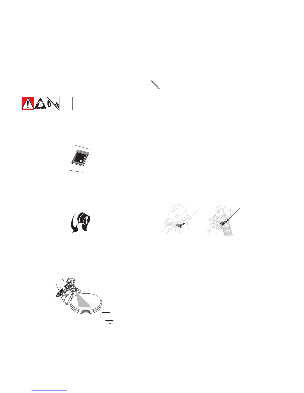
Trigger Lock
Always engage the trigger lock when you stop spraying
to prevent the gun from being triggered accidentally by
hand or if dropped or bumped.
Trigger Locked Position
(SG1-EF)
(SG2 and SG3)
PRIME
3. Hold a metal part of the gun firmly to a grounded
metal pail. Trigger the gun to relieve pressure.
10 309226M

General Repair Information
Flammable materials spilled on hot, bare, motor could
cause fire or explosion. To reduce risk of burns, fire
or explosion, do not operate sprayer with cover
removed.
• Keep all screws, nuts, washers, gaskets, and electrical fittings removed during repair procedures. These
parts usually are not provided with replacement kits.
• Test repairs after problems are corrected.
General Repair Information
To reduce risk of serious injury, including electric shock:
• Do not touch moving or electric pars with fingers or
tools while testing repair.
• Unplug sprayer when power is not required for testing.
• Install all covers, gaskets, screws and washers
before you operate sprayer.
CAUTION
• Do not run sprayer dry for more than 30 seconds.
Doing so could damage pump packings.
• If sprayer does not operate properly, review repair
procedure to verify you did it correctly. See Basic
Troubleshooting, page 12 and Advanced Trouble-
shooting, page 15.
• Overspray may build up in the air passages.
Remove any overspray and residue from air passages and openings in the enclosures whenever
you service sprayer.
• Do not operate the sprayer without the cover in
place. Replace if damaged. Covers direct cooling air
around motor to prevent overheating.
• Protect the internal drive parts of this sprayer from
water. Openings in the cover allow for air cooling of
the mechanical parts and electronics inside. If
water gets in these openings, the sprayer could
malfunction or be permanently damaged.
• Prevent pump corrosion and damage from freezing.
Never leave water or water-base paint in sprayer
when its not in use in cold weather. Freezing fluids
can seriously damage sprayer. Store sprayer with
Pump Armor to protect sprayer during storage.
309226M 11

Basic Troubleshooting
Basic Troubleshooting
The following troubleshooting guidelines from the Operating Instructions are included here as a preemptive measure
against Advanced Troubleshooting, page 15. Refer to Component Identification, page 8 for reference letters
used in table.
Problem Cause Solution
Power switch is on and sprayer is
plugged in, but motor does not run,
and pump does not cycle.
Pump does not prime. Spray-Prime/Drain Valve (J) is in
Spray gun stopped spraying. Spray tip is clogged. Unclog spray tip. See Operation Man-
Pressure is set at zero pressure. Turn Pressure Control Knob (C)
clockwise to increase pressure setting.
Motor or control is damaged. See Motor Does Not Operate, page
15.
Electric outlet is not providing power. • Try a different outlet or plug in
something that you know is working to test outlet.
• Reset building circuit breaker or
replace fuse.
Extension cord is damaged. Replace extension cord. See
Grounding and Electric Requirements, page 6.
Sprayer electric cord is damaged. Check for broken insulation or wires.
Replace electric cord if damaged.
Paint is frozen or hardened in pump. See Motor Does Not Operate, page
15.
Turn Spray-Prime/Drain Valve to
SPRAY position.
Inlet screen (L) is clogged or suction
tube (G) is not immersed.
Balls in check valve are stuck or
check valves are damaged.
Suction tube is leaking. Tighten suction tube connection (K).
PRIME/DRAIN position (pointing
down).
Clean debris off inlet screen and
make sure suction tube is at bottom
of paint pail.
Clean or replace check valves. See
Pump Service, page 25. Do not
store check valves in water.
Inspect for cracks or vacuum leaks.
ual, 309225.
12 309226M
 Loading...