

MagniSight MSE-L24-HD Explorer HD, MSE-L24-HD, Explorer HD MSE-L24-HD User Manual

R
MSE-L24-HD
Model A
User's Manual

Table of Contents
SECTION 1: Unpacking and Set-Up of System.................................. 2
SECTION 2: Features and Operating Instructions.............................4
Turning ON the System................................................................ 4
Selecting Viewing Mode...............................................................4
Adjusting Magnification...............................................................5
Adjusting Brightness....................................................................6
Switching Lights...........................................................................6
Using the Viewing Table...............................................................7
SECTION 3: Service and Safety Information......................................9
FCC Information:
Explorer CCTV’s has been tested and found to comply with the limits for a Class B digital
device, pursuant to part 15 of the FCC Rules. These limits are designed to provide
reasonable protection against harmful interference when the equipment is operated in its
installation. This equipment generates, uses, and can radiate radio frequency energy
and, if not installed and used in accordance with the instruction manual, may cause
harmful interference to radio communications. If this equipment does cause harmful
interference, the user will be required to correct the interference.
hdm-1a
1
Section 1: Unpacking & Set-Up
1. Remove User’s Manual and power cord from top foam compartments
and remove the upper foam packaging.
IMPORTANT: DO NOT DISCARD packing carton and materials.
In the event service or return of the unit is required in the
!
future, the original packaging is REQUIRED to insure no
damage occurs in shipping.
Recommend 2-Person Lift
For Next Step
2. Next, firmly grab hold of each side of camera unit and lift unit out of
the foam packing in the bottom of the carton. Place Camera System
on sturdy desk or table where it will be used.
Avoid places near any heat source or direct sunlight. P
Camera unit on the desk surface to your preferred location. The
bottom of the unit is equipped with rubber pads to protect the table
surface and to prevent the unit from sliding.
3. Next, remove packaging from around the Camera and Monitor.
osition the
2
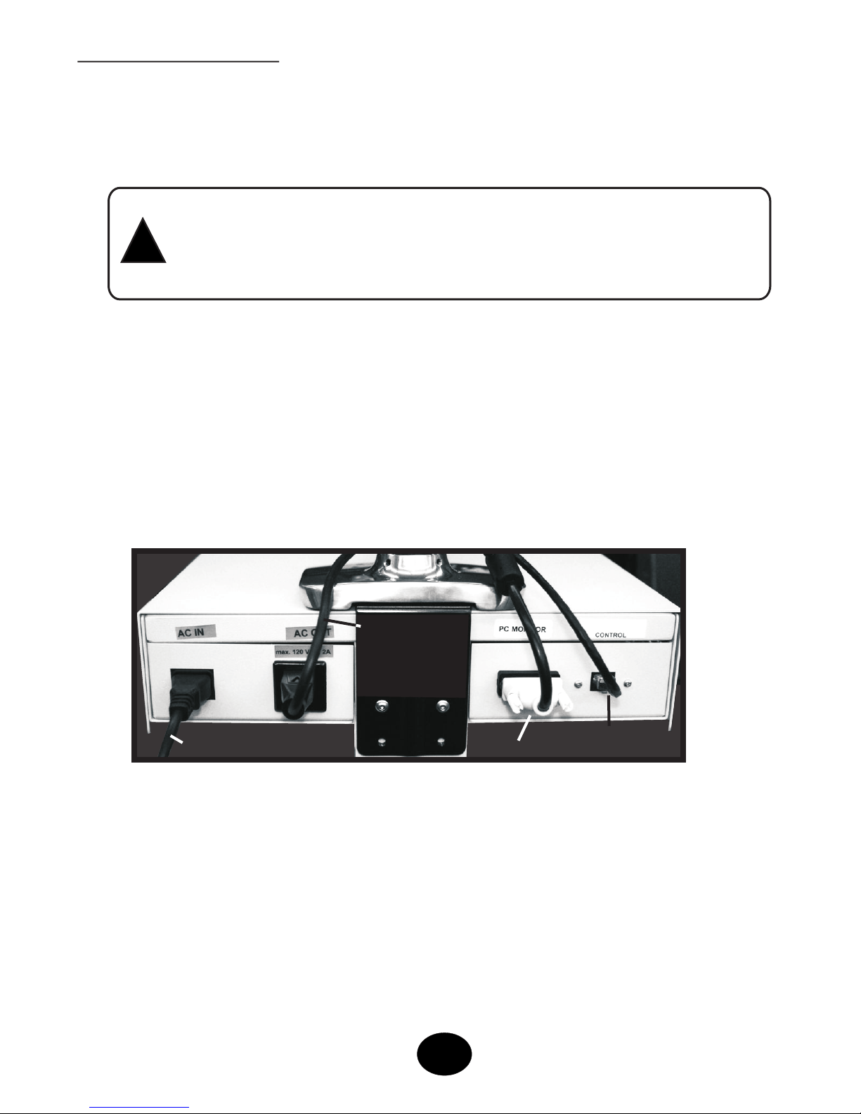
Set-Up (cont’d)
4. Connect the AC Power Cord to the AC IN jack on the rear panel of the
camera. Plug the other end of the AC Power Cord into wall outlet or
surge protected power strip (not included).
CAUTION: THE POWER SUPPLY CORD IS USED AS THE
MAIN DISCONNECT DEVICE. ENSURE THAT THE SOCKET-
!
OUTLET IS LOCATED NEAR THE EQUIPMENT AND IS
EASILY ACCESSIBLE
5. Next, connect the Monitor Power Cord on the rear
to the AC OUT jack
panel of the camera. Note: the power supplied to the AC OUT jack
turns on & off with the camera power switch.
6. Finally, connect one end of the DVI signal cable to the Monitor Jack
and the Control Cable to the Control Jack on the rear panel of the
camera.
Monitor
Power Cord
Power Cord (to Wall Outlet)
DVI Signal Cable
Control Cable
3
 Loading...