

Magnimage MIG-CL9004-B, MIG-CL9004-A, MIG-CL9004-C, MIG- CL9003-A User Manual

MIG-CL9000series
User manual V1.2
△
!
MAGNIMAGE
Before using this LED Video Wall Controller,please read this
manual carefully and preserved for reference in the future.
Video Wall controller

Without the written permission, any unit or individual could not copy,
reproduction or translate the book or part of it. Also could not
transmit it in any form or any way(electronic,mechanical,
photocopying, record or other way) for any business and profitable
purpose.
The product specifications and information mentioned in this manual
is just for reference, will not give prior notice if there is any updated.
Unless there is a special agreement, it is just used as guidelines. All
the statements or information in this manual shall not constitute any
form of guarantee.
Statements

Briefs ...................................................................................................... 1
Trademark Credit .......................................................................... 1
About Software ............................................................................. 1
Feature ........................................................................................... 2
Using Directions .................................................................................... 3
Attached accessories ..................................................................... 3
Safety Notice ................................................................................. 4
Function introduction ............................................................................ 5
Summary ....................................................................................... 5
technical specifications ......................................................................... 6
Front and rear panel of Video Wall controller ..................................... 7
MIG-CL9004Front panel ............................................................. 7
MIG-CL9004Rear Panel .............................................................. 8
MIG-CL9003Front panel .......................................................... 12
Directory

MIG-CL9003Rear Panel ........................................................... 13
Board Introduction ..................................................................... 15
Control board ..................................................................... 15
Output board ...................................................................... 16
Input board ......................................................................... 18
System menu ...................................................................................... 21
Status Icons ................................................................................ 22
Menu browsing .......................................................................... 22
Main menu ......................................................................... 23
Status information ............................................................. 24
Function setting ................................................................. 25
Communication setting ..................................................... 26
Language ............................................................................ 27
About Magnimage ............................................................. 28
Software .............................................................................................. 29
Operating environment .............................................................. 29

Installation .......................................................................... 30
Unloading ........................................................................... 32
Running software ....................................................................... 33
Connection window ........................................................... 34
Main Program Window ..................................................... 36
Guide Window ................................................................... 42
Software Using....................................................................... 44
Preparation ..................................................................... 44
New Project ........................................................................ 46
Save Project ....................................................................... 52
Open Project ...................................................................... 53
Deepen Understanding ...................................................... 54
Upper Software Interface Detail ............................................... 56
Layer Interface and Operation .......................................... 56
Related Interface and Operation of Input Source ............ 58
Output port related interface and operation ..................... 62

Scenario related interface and operation .......................... 66
Interface of System State .................................................. 67
Warranty .............................................................................................. 68
The whole unit warranty ............................................................ 68
The non-warranty provisions .................................................... 68
Quick use guide .................................................................................. 69

1
Thanks for your purchasing our LED Video processor. Do hope you can enjoy the
experience of the product performance. The design of the LED video processor
conforms to international and industry standards. But if with improper operation,
there will be a personal injury and property damage. In order to avoid the
dangerous, please obey the relevant instructions when you install and operate the
product.
VGA and XGA are the trademarks of IBM.
VESA is a Video Electronics Standards Association's trademark.
HDMI mark and High-Definition Multimedia Interface are all from HDMI
Licensing LLC.
Even if not specified company or product trademarks, trademark has been
fully recognized.
Do not change, decompile, disassemble, decrypt or reverse engineer the software
installed in the product, these acts are illegal.
Briefs
Trademark Credit
About Software

2
The pure hardware architecture, full channel RGB 24bit/60HZ
Support DP 4K * 2K input
Support adjusting the size and position of display layer, full screen roaming
Input - output signal real-time monitoring image (IP Replay function)
single outputs support 4 separate layers and a HD background
Save the work scene, and quickly call the template
DVI input, support EDID, support for customized output resolution
The group control for layers, fade switching for layers
Support a variety of control devices, IPAD and computer software
Support LED, LCD, projection screen splicing and fusion
The blade-board design, dual power backup
Feature
3
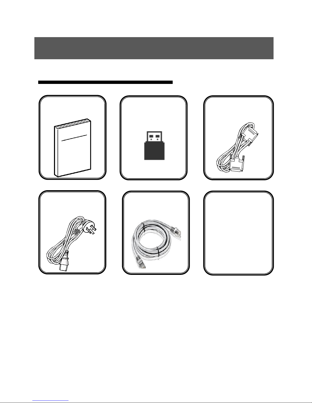
Attached accessories
Using Directions
manual×1
USB×1
Certificate×1
VGA×1
Powerline×2
Net cable×2
DVI cable×2

4
The power input voltage for this product is 100-240VAC50/60Hz, please use
the correct power supply
When you need to connect or plug out any signal or control line, please
confirm all the power line have been plugged out
When do you want to add hardware device into the product or to remove it,
please confirm all signal and power lines have been previously removed
Before any hardware operation, please prior switch offthe power of
MIG-CL9000, and you can release your body electrostaticthrough touch the
ground surface
Please use it in a clean, dry and ventilated environment, do not use this
product in high temperature and humid environment
This product is electronic products, please stay away from fire, water and
inflammable and explosive dangerous goods
this product has high pressure parts, please do not open the case or for the
maintenance of the equipment by yourself
supposing it has smoking, odor and other abnormal situation, please
immediately turn off the power switch, and contact with dealers
Safety Notice

5
CL9000 series can be divide into 4U case MIG-CL9004 and 3U case MIG-CL900
3 according to case size.
the MIG-CL9004 is divided into three sub models:
1. MIG-CL9004-A: with 4 output board slots, 8 input board slots
2 . MIG-CL9004-B: with 6 output board slots, 6 input board slots
3. MIG-CL9004-C: with 8 output board slots, 4 input board slots
MIG-CL9003 only have one model:
1. MIG- CL9003-A: with 4 output board slots, 5 input board slots
Function introduction
Summary
CYCLONEvideo wall controller is anvideo processing equipment of pure hardware
architecture, mainly be applied in LED large screen with small pixel spacing, realize
multi displays seamless splicing and runningmulti window,it can apply in security
monitoring, administration, military command, exhibition display, education and
scientific research and other industries.
CYCLONE host adopts thehardware architecture which based on large capacity high
speed FPGA array and high speed digital matrix, for a variety of input signal, internal
processing the RGB 24bits/60Hz, ensure the high reducibility of the signal, also built
in high performance scaling engine, support multi screen output when the seamless
splicing, to ensure the output image is clear, smooth, without delay.
Support for multi signal input, including DVI, VGA, HDMI, DP, SDI, AV, IP. EDID
management can be achieved on the input signal.
We provideafter-sale service forall series of products, support USB upgrade and
network control, convenient technical support and after-sale maintenance;
maintenance.
6
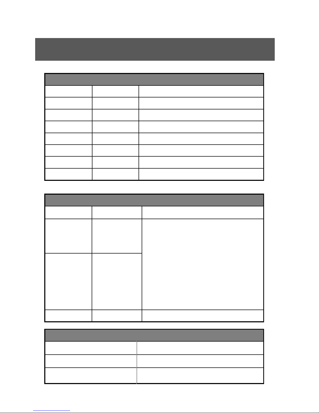
Technical specifications
Input signal index
Interface
Number
Specifications
VGA
4
VESA standard
DVI
4
VESA standard,support EDID
HDMI
4
HDMI-1.3standard
SDI
4
480i、576i、720p、1080i/p(3G SDI)
DP
2
DP 1.2 standard 3840×2160×30 Hz
AV
8
PAL、NTSC、SECAM
IP 2 H.264
Output signal index
Interface
Number
resolution
DVI-A
2×2
(Single port 4
layers)
1024×768/60Hz 1366×768/60Hz
1440×900/60Hz1440×1440/60Hz
1280×1024/60Hz 1680×1050/60Hz
1600×1200/60Hz1920×1080/60Hz
2560×816/60Hz customized output
resolution
Max in horizontal 2560, Max in Vertical
2560
DVI-B
4×1
( Single port 2
layers )
IP
1
Network IP replay
Electrical specifications
Input power
100~240VAC,50/60Hz
working temperature
0~45℃
working temperature
10% -90% non-condensing
7
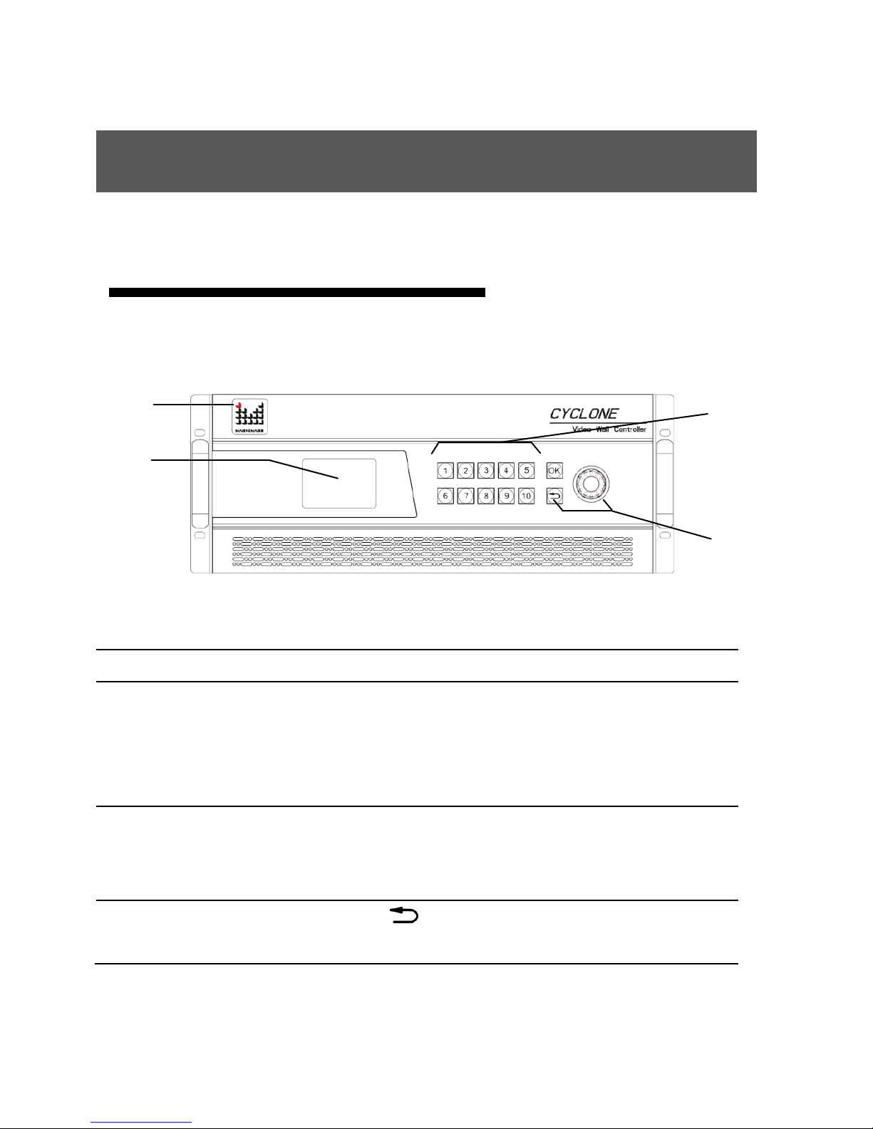
Front and rear panel of Video Wall controller
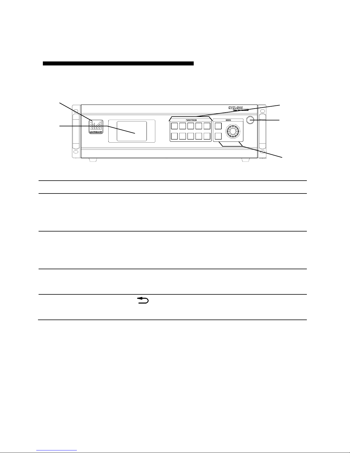
MIG-CL9004Front panel
1、LOGO
Magnimage
2、LCD display
Mainly used for showing the status of the device,
including the input and output board configuration,
firmware version, ambient temperature, network
configuration and other information
3、Functional key
area
Buttons 1~10, for the input of the machine
configuration information, such as the IP address in the
network configuration, subnet mask, etc.
4、Menu operation area
OK key、 key,As well as the knob;using LCD
display,can browse the local menu system
2 4 1
3
8
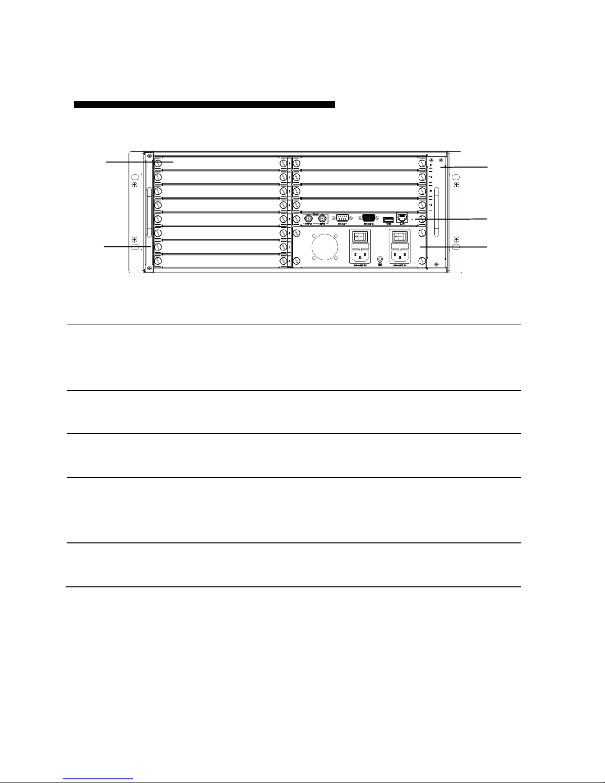
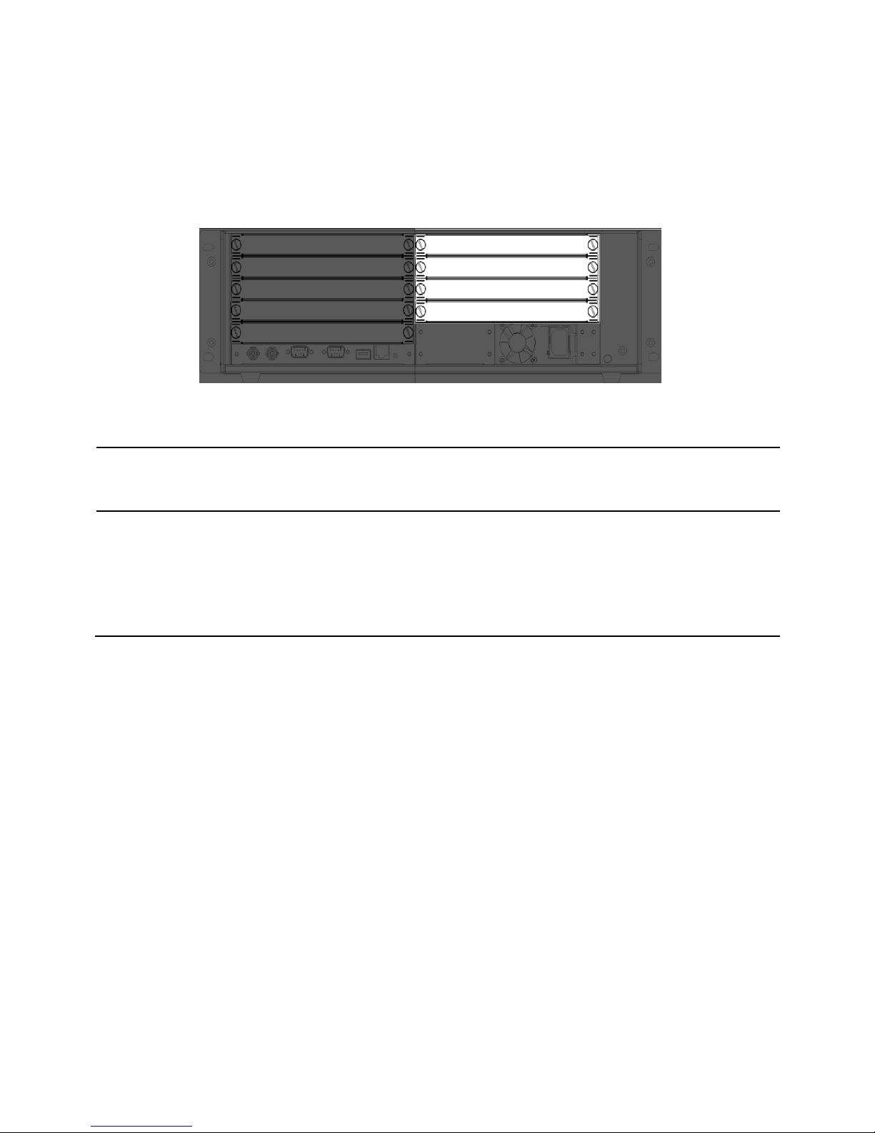
MIG-CL9004Rear Panel
1、Board slot
MIG-CL9004 has a total of 12 board slots, in the
back of the case, it has 1 to 12 of the
numericalidentification
2、Dust-against bracket
The dust-against bracket can be disassembled
conveniently for replacinga new one.
3、Fan bracket
Fan bracket can be easily removed for cleaning or
replacing
4、Control board
Control board is the MIG-CL9004 control center,
with a serial ports, network port, USB port, as well
as reference synchronization port
5、 the power
the power supply adopts double power supplies
backup, and its provided with anearth wire
3
4
5
1
2 3 4
5

9
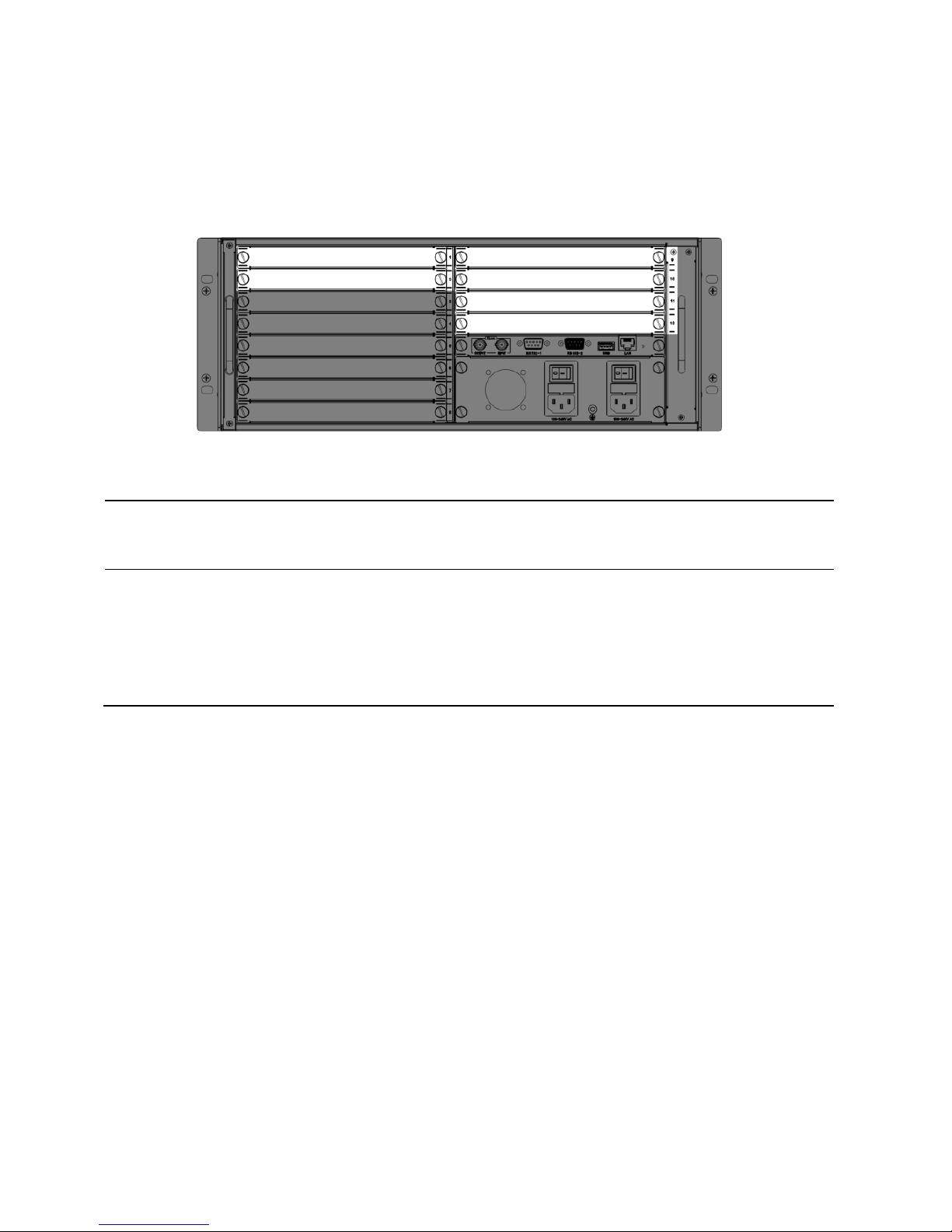
MIG-CL9004-A
Input configuration
area(the dark area)
8 input board slots (1st to 8th slots),
Outputconfiguration
area(the light area)
4 output board slot (9th to 12th slot), each board slot
supports the main output, multi images preview output or
network IP replay
10
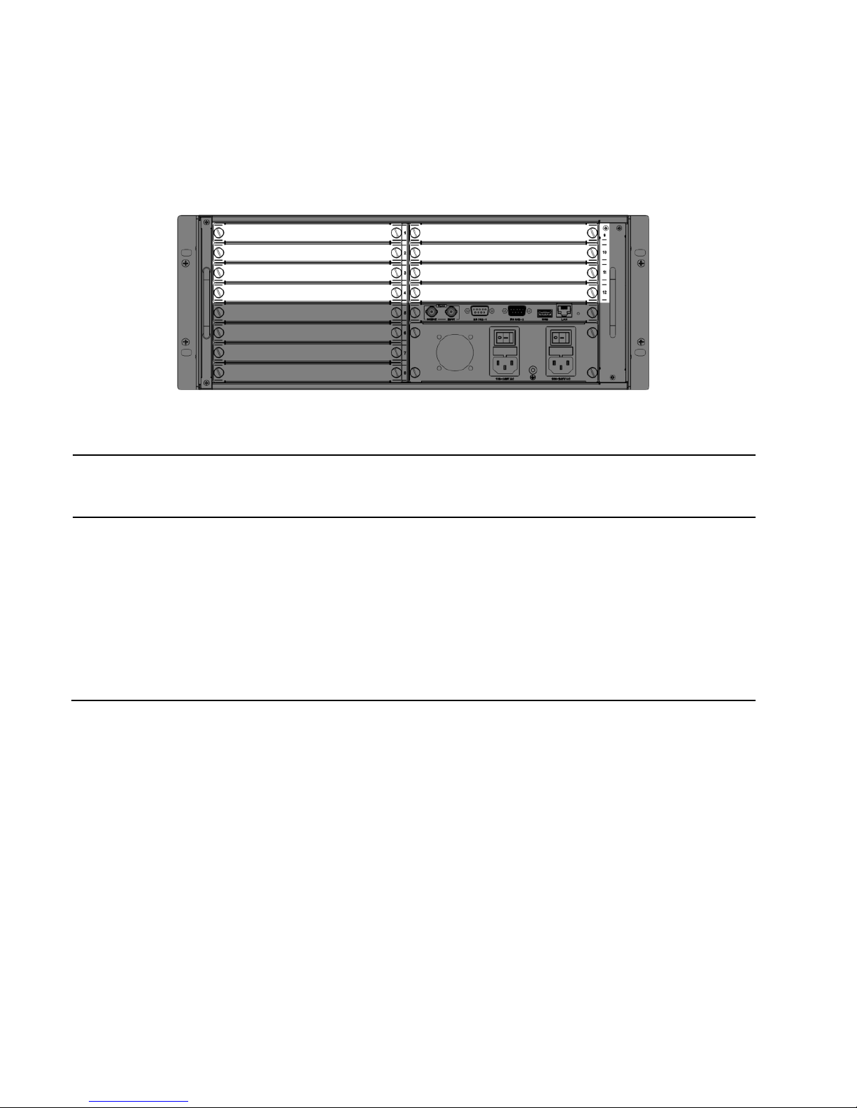
MIG-CL9004-B
Input configuration
area(the dark area )
6 input board slots (3rd to 8th slots),
Outputconfiguration
area(the light area )
6 output board slots (1st, 2nd, and 9th to 12th board slots),
all the output board slotssupport the main output, but only
11th, 12th board slots can support multi images preview
output or network IP replay
11
MIG-CL9004-C
Input configuration area(the
dark area)
4 input board slots (5h to 8th slots),
Outputconfiguration area(the
light area)
With eight output board slots (from the 1st to the 4
and 9 to 12 slots), all output board slot support main
output, but the only 12th board slot can support multi
images preview or network IP replay, butit will
occupy the 11th board resource and make the 11th
slot invalid
12
MIG-CL9003Front panel
1、LOGO
Magnimage
2、LCD display
Mainly used for showing the status of the device, including the
input and output board configuration, firmware version, ambient
temperature, network configuration and other information
3、Functional key
area
Buttons 1~10, for the input of the machine configuration
information, such as the IP address in the network
configuration, subnet mask, etc.
4、 the power
the power supply adopts double power supplies backup, and its
provided with anearth wire
5、Menu
operation area
OK key、 key,As well as the knob;using LCD display,can
browse the local menu system
1
2
3 5 4
13
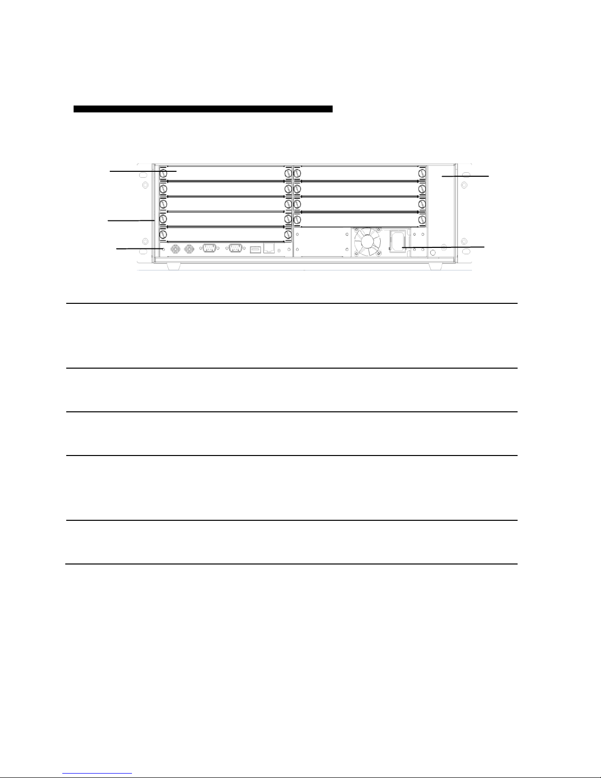
MIG-CL9003Rear Panel
1、Board slot
MIG-CL9003 has a total of 12 board slots, in the
back of the case, it has 1 to 12 of the
numericalidentification
2、Dust-against bracket
The dust-against bracket can be disassembled
conveniently for replacinga new one.
3、Fan bracket
Fan bracket can be easily removed for cleaning or
replacing
4、Control board
Control board is the MIG-CL9003 control center,
with a serial ports, network port, USB port, as well
as reference synchronization port
5、 the power
the power supply adopts double power supplies
backup, and its provided with anearth wire
1
2
3
5
4
14
MIG-CL9003-A
Input configuration
area(the dark area)
8 input board slots (1st to 5th slots),
Outputconfiguration
area(the light area)
4 output board slot (6th to 9th slot), each board slot
supports the main output, Only 6th slot can support multi
images preview output ;MIG-CL9003 cannot support
network IP replay
15
MIG-CL9000 series of multi videos controller has abundant boards for selection.
The control board, as a standard configuration, is the core part of the whole device;
input and output boards are matched configuration which can be matched freely
according to the actual demand.
In addition, the output board generally has 2 kinds of working modes, namely:
standard output mode, as well as multi screen preview mode. These modes will be
described in detail in the following.
Board Introduction
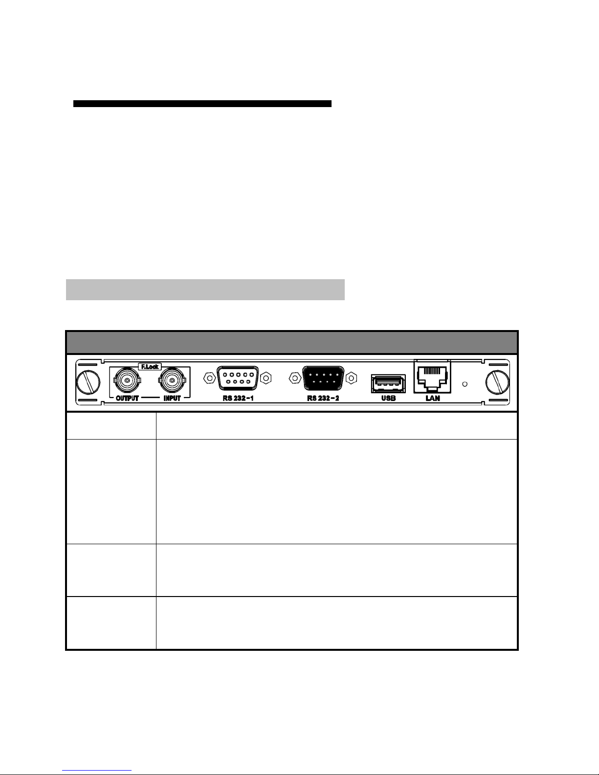
Control board
Control board
F. Lock
Frame synchronization locking signal input and output interface
RS 232-1/2
RS232-1 is a serial port control interface for connection control
equipment;
RS232-2 is the external matrix control interface, used to control
the external matrix
USB
The USB interface is used to update the firmware, or for import
HD background configuration information
LAN
Network control interface, used to connect the host computer; the
controller's LAN port IP address
16
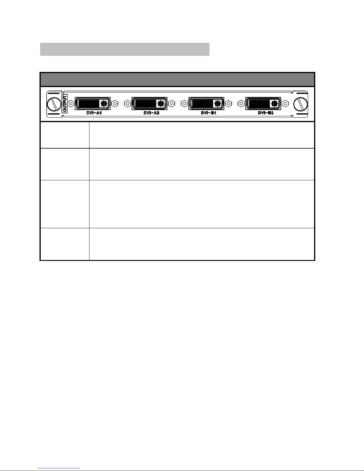
MIG-CL9000-OUTDVI-A: [DVI 2×2@4Layer Output board]
DVI
interface
4 DVI ports were divided into 2 groups (group A and group B), each
group of 2 DVI ports were used to the replicate model output.
Working
mode
2 groups of ports can beswitched between standard output mode and
multipreview mode through the way of upgrading firmware
Layer
description
Standard output mode, it supports four separate image layers, and a
HD background; while, in multi preview mode, it supports nine
tiled image layer
Output
resolution
The best output resolution is 1920 x 1080@60Hz, and supports
customized output resolution
Output board
17
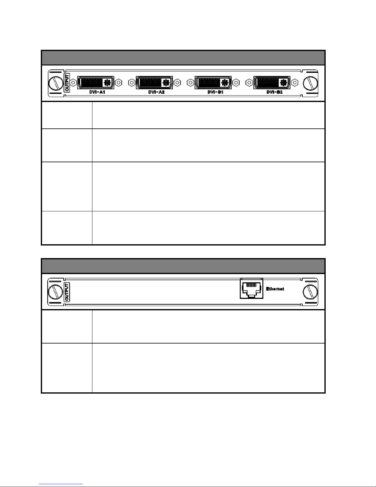
MIG-CL9000-OUTDVI-B: [DVI 4×1@4Layer Output board]]
DVI
interface
4 DVI ports can output 4 different signal separatedly
Working
mode
All ports can beswitched between standard output mode and multi
preview mode through the way of upgrading firmware
Layer
description
Standard output mode, it supports two separate image layers, and a
HD background; while, in multi preview mode, it supports nine
tiled image layer
Output
resolution
The best output resolution is 1920 x 1080@60Hz, and supports
customized output resolution
MIG-CL9000-OUTIP: [network IP replay]
Working
mode
This output board cannot switch into the working mode, only for
real-time transmitting input signal of the image to the PC
Board
instructions
The output card is used for real-time preview of the input image of
the upper machine installed on the PC, and it can support the images
of the 18 input signal source simultaneously.
18
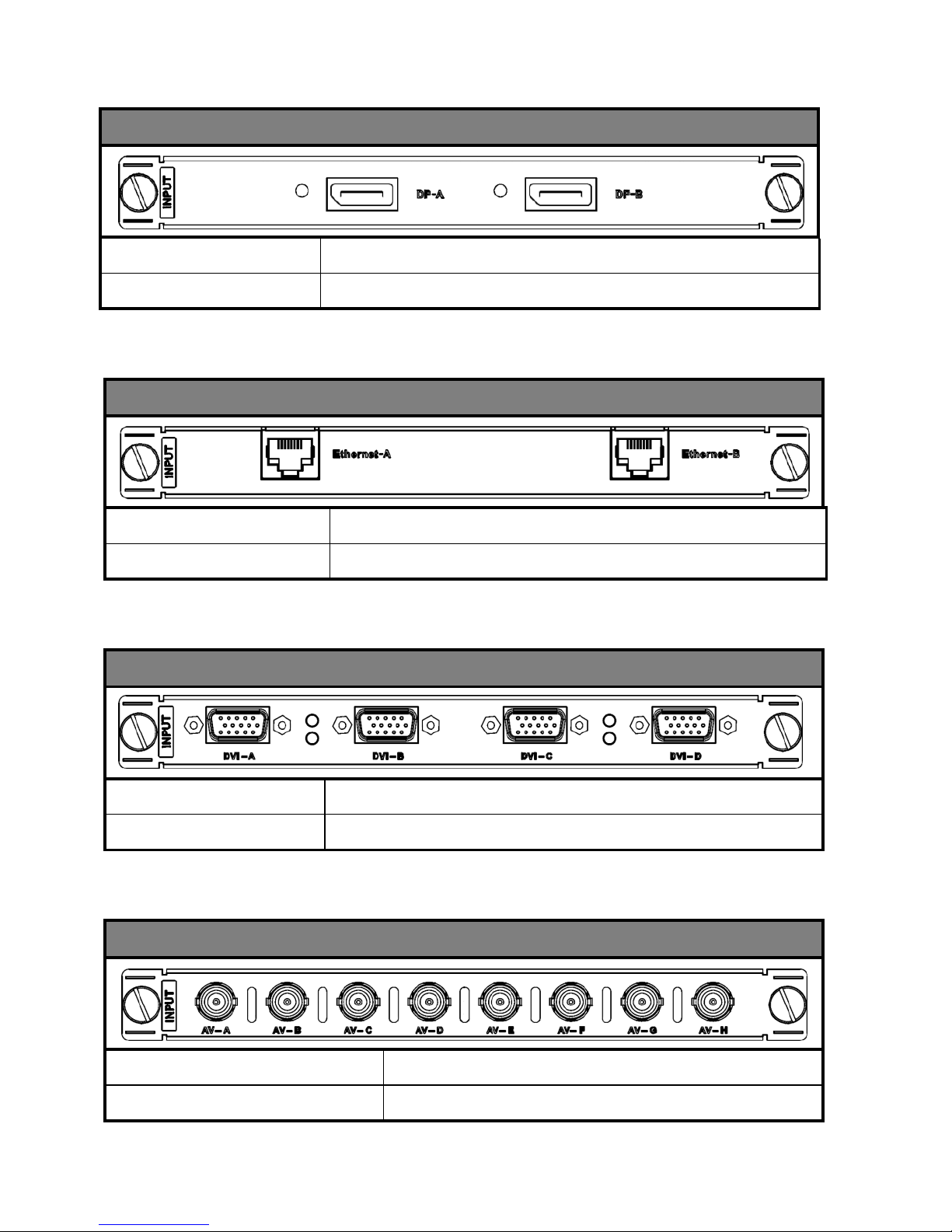
MIG-CL9000-INHDMI: [HDMI×4 Input Board ]
Signal specification
EIA/CEA-861 standard, HDMI-1.3 standard
Interface description
HDMI Type A
Input board
MIG-CL9000-INDVI: [DVI×4 Input Board]
Signal specification
Support only VESA standard DVI-D digital signal,
support EDID management function
Interface description
24+5 pin / head interface
MIG-CL9000-INSDI: [SDI×4 Input Board ]
Signal specification
480i、576i、720p、1080i/p(3G SDI)
Interface description
BNC / head interface
19
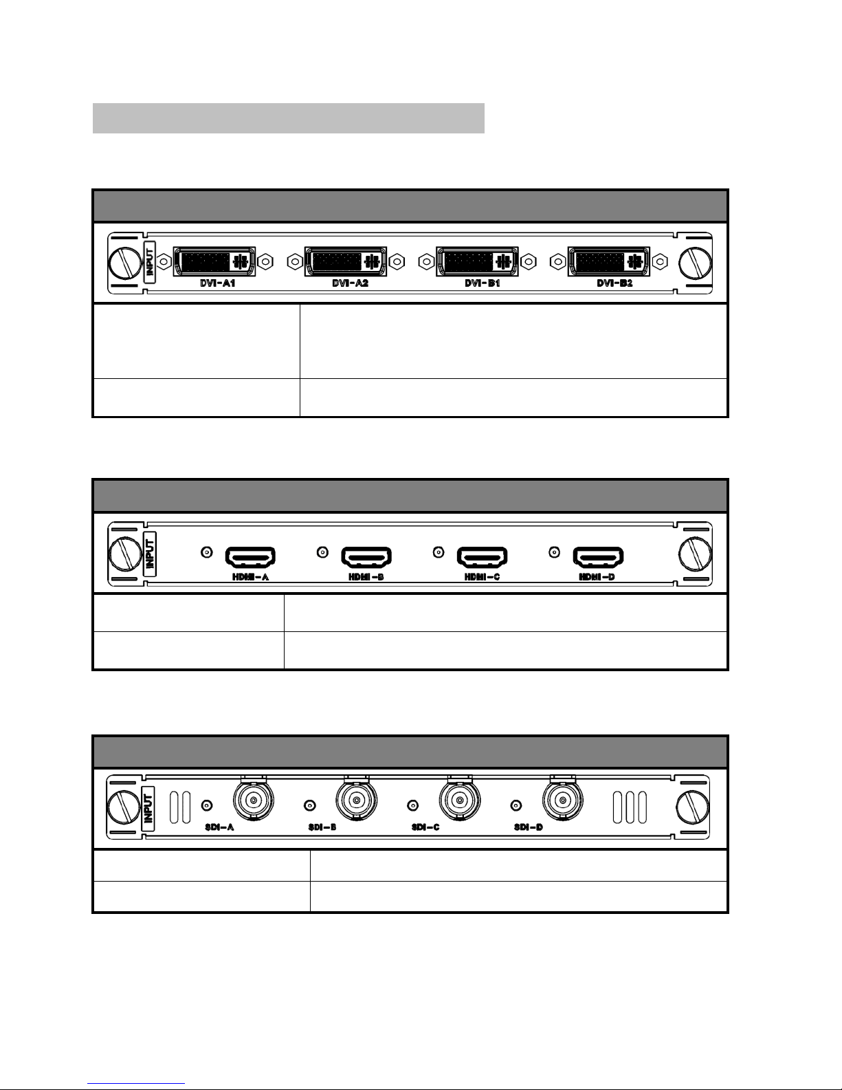
MIG-CL9000-INIP: [IP×2 Input Board]
Signal specification
IP Video streaming / H.264
Interface description
RJ45 × 2
MIG-CL9000-INVGA: [VGA×4 Input Board]
Signal specification
VESA standard
Interface description
15pinD-sub / head interface
MIG-CL9000-INAV: [AV×8 Input Board]
Signal specification
PAL / NTSC / SECAM
Interface description
BNC / head interface
MIG-CL9000-INDP: [DP×2 Input Board]
Signal specification
DP1.2 (3840×2160×30hz)
Interface description
Full Size 20 pin
20
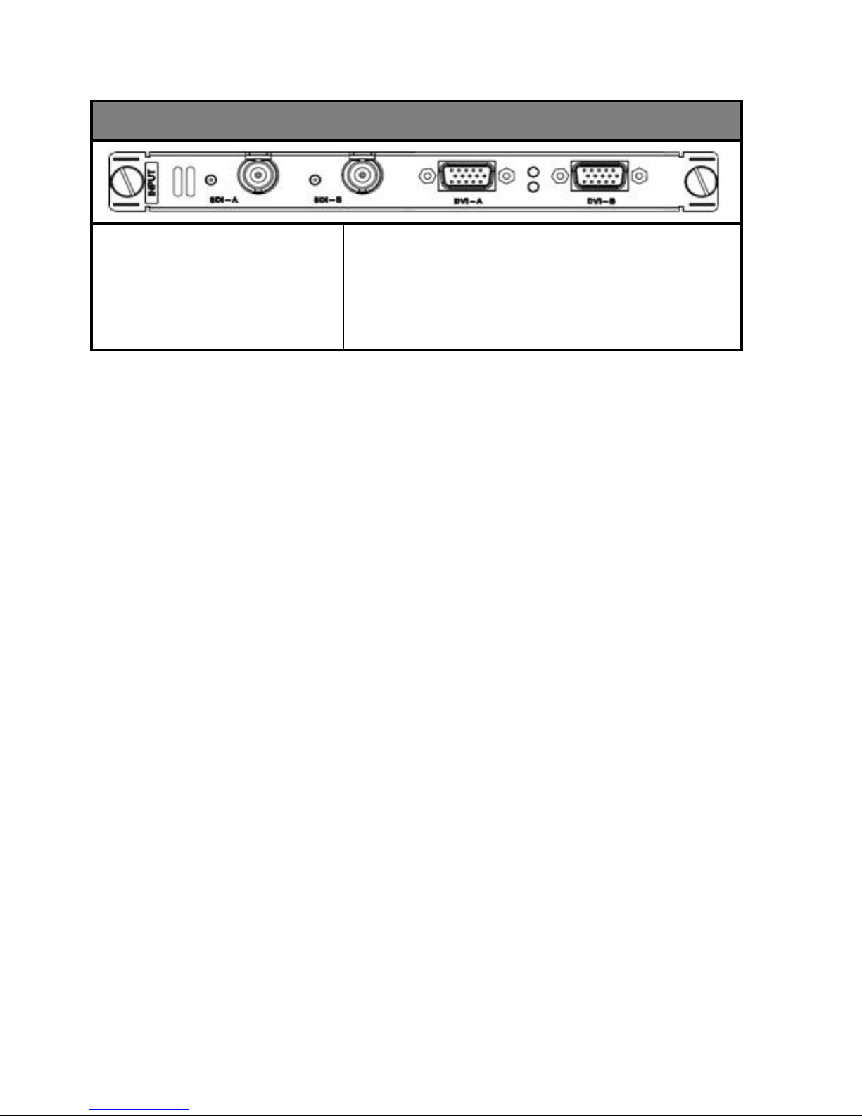
MIG-CL9000-INSDIVGA: SDI×2& VGA×2
Signal specification
SDI:480i、576i、720p、1080i/p(3G SDI)
VGA:VESA Standard
Interface description
SDI:BNC / head interface
VGA:15pinD-sub / head interface
 Loading...