

Magnifico MR3, MR31, MR4, MR321, MR32 Use And Maintenance Manual
...
USE AND
MAINTENANCE
MANUAL
MR3 - MR31 - MR4 - MR321 - MR32 - MR42
ME423 - ME4232 - ME523 - ME5232.. MME523
ME5 - ME52.. - MME52
ME7 - ME72.. - MME72
ME10 - ME102.. - MME102
MG5 - MG52 - MMG52
MG7 - MG72 - MMG72
MG10 - MG102 - MMG102
Rev. 2013-06.05
3
Use and maintenance manual
2
Index
1. Installation
1.1
General and safety warnings
3
1.2
Connection to gas supply
4
1.3
Checking gas pressure
6
1.4
Replacing nozzles (gas type change)
6
1.5 Electric connection 7
1.6
Fume discharge
8
1.7
Connection to the drain
8
1.8 Switching on oven and testing 9
2. Use instruction
2.1 Preliminary information 10
2.2 Control Panel 11
2.3 Convection cooking 12
2.4 Steaming 13
2.5 Convection/steam combi cooking 14
2.6 Humidity draining valve 15
2.7 Compartment lighting 15
2.8 Stop and oven swich off 15
2.9 Flame control (gas ovens only) 15
2.10 Other versions 16
4. What to do if...
4.1 Most common problems 18
4.2 Safety thermostat of the cooking
compartment
19
3. Maintenance
3.1 Cleaning 17
3.2 Cleaning of the glass 17
Dear Customer,
We thank you for having purchased our product.
This oven is part of a line of appliances specically designed for baking and patisserie, made of gas and electric
ovens with different capacities. The pleasant and modern design of these ovens provides ease of use, ergonomics
and cooking control.
The oven has a 12 month warranty against any manufacturing faults, starting from the date on the sales invoice.
The warranty covers the normal functioning of the oven and does not include the consumption materials (lights,
gaskets, etc.) and faults caused by incorrect installation, wear, maintenance, repair, decalcication & cleaning,
tampering and improper use.
The manufacturer reserves the right at any time to make changes or necessary amendments to the product.
• Carefully read this manual before installing and com-
missioning the oven. The text gives important indications regarding the safe installation, operating and
maintenance of the equipment.
• Keep this manual in a safe and easily accessible place
for further consultation by the operators.
• In case of transferring the oven, always attach the ma-
nual; if necessary, a new copy must be requested from
the authorised dealer or directly from the manufacturing company.
• Once unpacked, ensure the oven is intact and does not
show signs of damage due to transport. A damaged
appliance must never be installed and commissioned; if
in doubt, immediately contact the after-sales technical
assistance or your own dealer.
• The appliance has been designed to cook food in closed
premises and must only be used for this purpose: any
other use must, therefore, be avoided as considered
improper and dangerous.
• The device is intended for professional use only by qua-
lied personnel
• The oven must only be used by staff adequately trained
for its use. To avoid the risk of accidents or damages to
the appliance, it is also fundamental that staff regularly
receive precise instructions regarding safety.
• The oven must not be used by persons with reduced
physical, sensorial or mental capacities or by persons
without experience and knowledge, unless supervised
or educated regarding the operating of the appliance by
a person responsible for their safety.
• Installation, extraordinary maintenance and repair
operations on the equipment must only be carried out
by professionally qualied staff.
• Children must be supervised to assure they do not
play with the appliance or use it.
• Caution! During working conditions, the external sur-
faces of the equipment may exceed 60 C.
• In case of fault or bad functioning, the equipment
must be deactivated; in case of repair, contact only
an after-sales technical assistance centre authorised
by the manufacturer and request original spare parts.
• Do not position other heat sources like, fryers or
hotplates, near the oven.
• Do not deposit or use ammable substances near the
equipment.
• In case of prolonged disuse of the appliance, both the
water and electric energy supply must be shut-off.
• Before commissioning the equipment, ensure to have
removed all packaging, being careful to dispose of it in
compliance with the Standard in force.
• Amendments to the oven wiring are not admitted.
• The non-compliance with the above warnings can je-
opardise the safety of the equipment and may injury
the operator of the oven.
The gas ovens comply with the essential requirements of 90/396/EEC Gas Directive and therefore have the EC
conformity certicate issued by an approved body. They satisfy the requirements of the following gas regulations:
• EN 203 + subsequent amendments;
• EN 437 + subsequent amendments.
Installation must be carried out in compliance with safety requirements contained in the following regulations:
• UNI CIG n° 7222-7723-8723 + subsequent amendments.
The appliance complies with the essential requirements of the Low Voltage Directives 2006/95/CEE. It satises the
requirements of the following electrical regulations:
• EN 60335-1 + subsequent amendments;
• EN 60335-2-42 + subsequent amendments;
• EN 60335-2-46 + subsequent amendments;
• EN 60335-2-36 + subsequent amendments;
• EN 55104 / EN 55014 + subsequent amendments;
• EN 61000 + subsequent amendments.
The appliance complies with the essential requirements of the Electromagnetic Compatibility Directive 2004/108/
CEE.
1. Installation
1.1 General and safety warnings
5. Data sheet
5.1 ME523 - ME5232 - MME523 19
5.2 ME5232X - ME5232K1 - ME5232K2 20
5.3 ME5 - ME52 - MME52 - ME52X 21
5.4 ME7 - ME72 - MME72 - ME72X 21
5.5 ME10 - ME102 - MME102 - ME102X 22
5.6 MG5 - MG52 - MMG52 23
5.7 MG7 - MG72 - MMG72 23
5.8 MG10 - MG102 - MMG102 24
5.9 MR3 - MR32 - MR31 - MR312 25
5.10 MR4 - MR42 25
5.11 ME423 - ME4232 26
6. Electrical drawings
Electrical drawings 27-42

5
Use and maintenance manual
4
1. Installation
1.2 Connection to gas supply (for gas ovens only)
The oven is factory set for the type of gas spe-
cied in the order.
The label attached to the appliance indicates
which type of gas the oven has been set for.
During testing, the gas produced through combustion (CO2 and CO) should be
analysed and the nominal heat rating
should be measured to ensure that the
burners have been correctly calibrated
for the type of installation required.
Data collected should be written down and included in the technical documentation of the
appliance.
Installation instructions
The oven should be installed and commissioned by qualied technicians in compliance
with current regulations and legislation.
Gas appliances, electrical connections and rooms where the appliance is to be sited
must comply with current regulations and legislation.
The air requirement of the burners is 2 m3/h per kW of power installed.
Premises open to the public must comply with accident prevention laws and re safety
regulations. A exible metal hose can be used to connect the appliance to the gas supply; make sure you t an approved tap in a point that is easy to reach.
Make sure that the exible hose is not twisted or over-stretched or in contact with parts
of the oven subject to overheating.
Use locking clamps complying with installation regulations.
Checks to be carried out prior to installation.
Check the label on the left-hand panel of the oven to make sure that the appliance has
been set for the type of gas on your premises.
Check the label to make sure that the capacity of the gas pressure reducer is adequate
for the supply of the appliance.
Do not insert section reducers between the reducer and the appliance.
We recommend tting a gas lter between the tap and pressure regulator to ensure
perfect performance.
Connect the oven to the gas supply using a special R 1/2”
hose with an internal section of at least 16 mm.
Connection to gas supply must be carried out using rigid or
exible metal pipes. Use taps or gates with an internal diame-
ter that is greater than that of the hose.
After connecting the appliance to the gas supply make sure
that there are no leaks from joints or connections. You can
test for leaks by using soapy water or foaming agent for leak
detection.
Gas ovens should be inspected in compliance with spe-
cic regulations once a year by an authorised techni-
cian who will analyse combusted gases and check no-
minal heat rating.
The appliance can work correctly only when gas pres-
sure keeps within specic values for each gas type (see
table).
If the pressure falls outside these values, it will not be possible
to achieve optimum functioning of the appliance and for it to
be installed correctly. Should this happen, call a technician to
check your gas mains (ducts, gates and eventually pressure
reducers) then, if necessary, contact your gas provider.
1. Installation
7
Use and maintenance manual
6
1. Installation
1.3
Control of Gas Pressure (for gas ovens only)
Check that the installed nozzles are correct for the type and pressure of supplied gas. If you need to change the
nozzles, read the following paragraph.
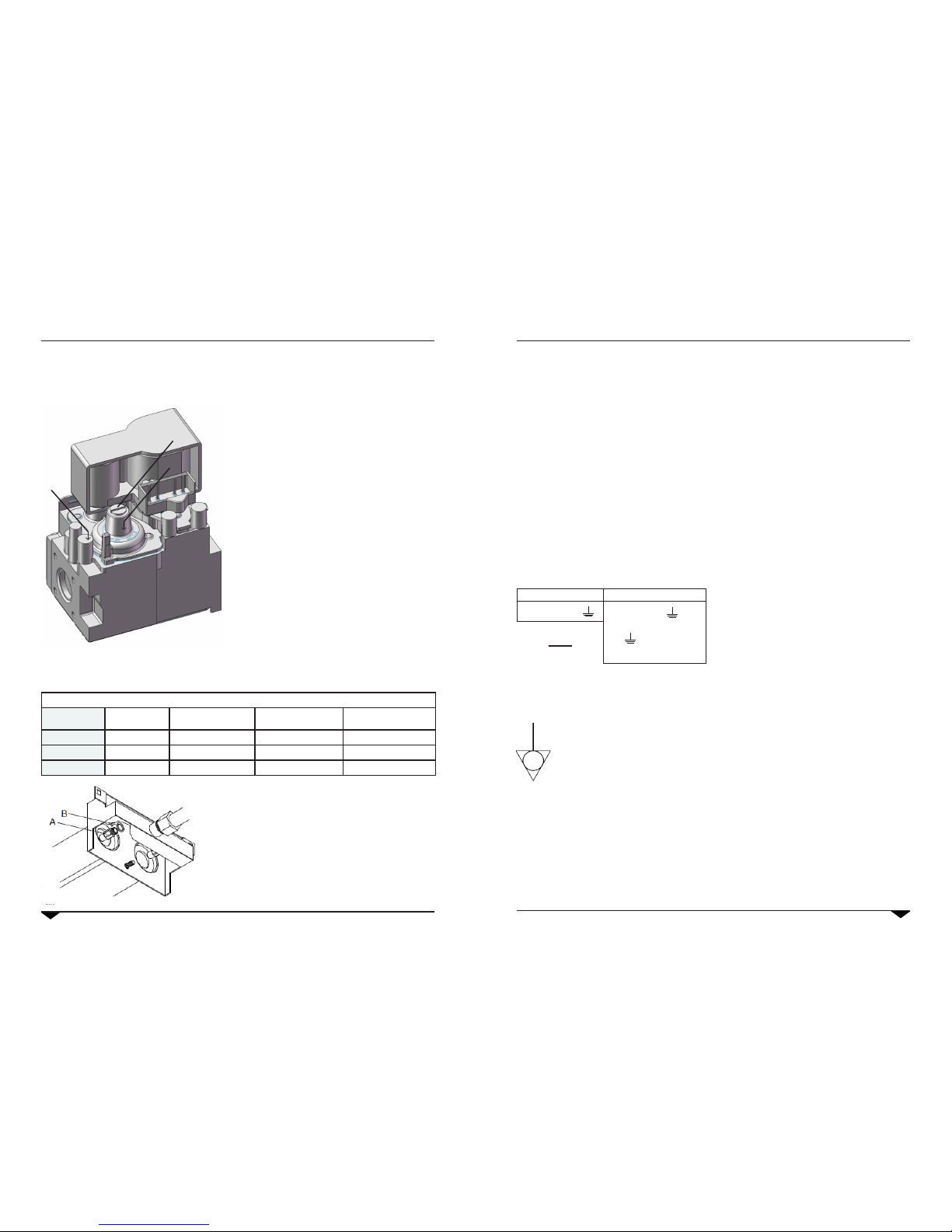
1.4
Replacing nozzles (gas type change) (for gas ovens only)
Category of appliance: II2H3+ Country: IT- ES -PT- CH-GB -GR - IE
Oven
Nominal
Power
Nozzle for
G30 gas [30 mbar]
Nozzle for
G31 gas [37 mbar]
Nozzle for
G20 gas [20 mbar]
5 GN 1/1 9,5 kW 115 110 161R
7 GN 1/1 16 kW 145 135 195R
10 GN 1/1 19 kW 155 145 225R
Use only original nozzles which must not be tampered with them in any way!
For connection to a type of gas that is different from the
one specied on the rating plate, the burner/s and nozzle/s
must be replaced as follows:
• Unscrew nozzle to be replaced and replace it with the
one that corresponds to the type of gas to be used.
• Ret washer.
• Nozzles are marked in hundredths of a millimetre.
• After replacing the nozzle/s, check gas pressure.
When the appliance is connected, turn it on and check the
gas pressure.
Check gas pressure directly on the valve, as described
below:
• Unscrew screw “P” on the pressure outlet of the valve.
• Apply the pressure gauge to the pressure outlet.
• Regulate gas pressure to the values of table 2 by adju-
sting the pressure reducer outside the oven
• When the pressure is at the correct level, switch off
the oven, remove the pressure gauge and replace
screw “P”.
If the adjustment of the pressure is not sufcient, act as
follows:
• Remove the protective cap A.
• Screw to increase the pressure of the outlet gas acting
on the screw B and unscrew to decrease.
• At the end of the calibration reapply the protective
cap A.
A
P
B
1. Installation
1.5
Electric connection
The electric system, as prescribed and specied by the Standard in force, must be
equipped with an efcient ground. It is possible to guarantee the electric safety of the
appliance only in the presence of Standard electric system.
For direct connection to the mains, it is necessary to interpose a device between the
equipment and the same mains, sized for the load, that ensure its disconnection. The
contacts must have an opening distance enabling the full disconnection, in conditions
of over-voltage category III, per compliance with installation regulations.
This device also must be located in a place and in a manner to be easily accessible at
any moment by the operator.
Bring the main switch, to which the power supply cable plug will be collected, in position
0 (zero).
Have professionally qualied staff check that the plug cables section is adequate to the
power used by the appliance.
Loosen the screws xing the left side of the oven and extract it.
Connect the cable to the terminal board
following the indications on “tab 1”.
Lock the cable with the cable presser.
The power supply voltage with machine
functioning,must not be different from the
nominal voltage value by ±10%.
The equipment must be included in an equipotential system which efciency must be
checked according to that reported in the Standard.
For the connection there is a clamp, located on the frame and marked with the symbol
to which a cable with minimum section of 10 mm² must be connected.
For gas ovens, complete gas connection to the appliance before assembling the
oven side again;
for electric ovens assemble the oven side.
ELECTRIC OVENS GAS OVENS
L1 L2 L3 N N L N X
tab 1
Between phases
and there must be
a potential difference
of 230 V
9
Use and maintenance manual
8
1. Installation 1. Installation
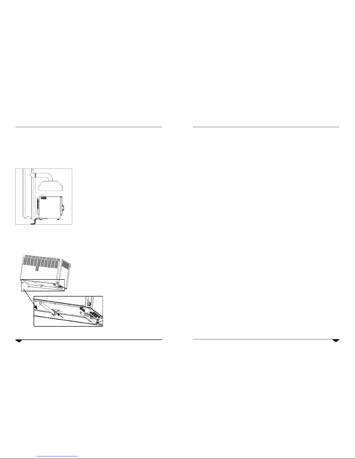
1.6
Fume discharge (for gas ovens only)
Ovens should only be installed in adequately ventilated rooms in compliance with installation regulations.
The oven discharge can be connected by means of a forced evacuation system (e.g. hood tted with an extractor
fan). In this case the gas supply to the appliance must be controlled by the extraction system and will be interrupted
if the extraction capacity drops below the prescribed values. When installing the appliance beneath a hood take
care to ensure that:
a) the extracted volume is greater than the volume of com-
busted gas produced (refer to current regulations);
b) the hood lter is made from a heat-resistant material
(combusted gases may reach 300°C;
c) the nal section of the gas discharge tube must be inser-
ted inside the hood;
d) following interruption of gas supply the gas will be
switched on manually.
1.8 Switching on oven and testing
Before switching on the oven, carefully check that all systems and installation of the appliance are in compliance
with current laws and with the technical and safety guidelines in this manual.
Check the following:
• The oven must be installed in a room where the temperature is over +4° C.
• The oven chamber must be empty.
• All packaging has been completely removed, including the protective lm applied to the walls of the oven.
• Vents and ventilation openings must be open and unobstructed.
• Any parts that have been removed for installation purposes must be replaced.
• The main switch must be switched on and the water and gas taps must be open.
Testing
The oven should be tested by carrying out a trial cooking session to check that the appliance is working properly and
that there are no problems or malfunctioning.
Switch on the oven by turning the cooking mode knob to the preferred position (convection, steam, combi) and by
turning the timer knob to a time position or on the innite symbol.
Carry out a trial cooking session setting the temperature to 150° C, the timer to 10 min. and humidity (if present).
Check every item in the list below:
• The light in the oven chamber switches on.
• The oven switches off if the door is opened and starts up again after the door has been closed.
• The temperature controller regulating the oven temperature is activated, causing the heating elements to
switch off temporarily.
• Every 2 minutes the fan motor automatically reverses direction of rotation followed by a 20-second rest.
• During the 20-second motor rest the S1 “°C” lighting indicator will temporarily switch xed-on showing that
the oven chamber heating elements have been temporarily switched off.
• For 7-tray and 10-tray ovens: the two fans in the oven chamber rotate in the same direction.
• Check that water is being discharged to the fan/s from the humidity inlet duct in the oven chamber (models
with humidier only).
• At the end of the cooking session the oven alarm sounds for about 15 seconds.
1.7
Connection to the drain
The oven must be connected to an open drain (funnel).
There is a sleeve (A) present in the lower part of the cooking
chamber (in the centre)to which the bendand and the rigid pipe
supplied (p) must be connected. Couple the bend in the rigid pipe
and connect it to the oven. Now, take the rigid pipe into the funnel
(not provided).
Another exible hose is present, which connects the front basin.
This hose must also be made to ow into the funnel.
A
B
p
11
Use and maintenance manual
10
2. Use instructions (combi-ovens)
2.1 Preliminary information
The appliance has been designed to cook food in
closed premises and must only be used for this pur-
pose: any other use must, be avoided and conside-
red improper & dangerous.
Survey the equipment during functioning.
Before cooking, we recommend pre-heating the
oven at a temperature of about 20/25% higher
than that required. Once the pre-heating tempera-
ture is reached, insert the food in the oven cavity,
and lower the temperature to the one desired for
cooking.
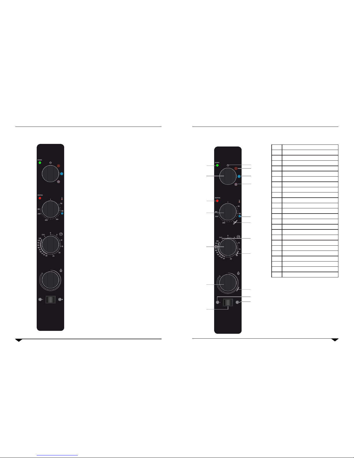
2.2 Control panel
M 1 Cooking mode / OFF knob
I 1 OFF position
I 2 Convection position
I 3 Steaming position
I 4 Mix (steam / convection) position
M 2 Temperature knob
I 5 Steaming treshold position
S 1 Temperature scale in °C
M 3 Timer knob
I 6 Innite time position
S 2 Timer scale in minutes
M 4 Humidity knob
S 3 Humidity scale
T 1 TIME / PROBE selector
I 8 TIME position
I 9 PROBE position
T 2 Fan speed selector
I 7 FAST fan position
I 10 SLOW fan position
D 1 Core probe temperature display
T 3 Core probe DOWN temperature
T 4 Core probe UP temperature
T 5 SET button
led 1 Oven status: ON / OFF
led 2 Heating element /s status: ON / OFF
2. Use instruction (combi-ovens)
I 1
I 2
I 3
I 4
I 5
S 1
S 2
S 3
I 7
I 8
M 1
M 2
M 3
M 4
I 6
led 1
led 2
T 1
13
Use and maintenance manual
12
2.3.1 Convection cooking with moisture.
To add moisture to the convection cooking turn the
M4 knob to the desired moisture grade. Turn the M4
knob to left to reduce the moisture production.
When the M4 knob in in up-vertical position the hu-
midier is off.
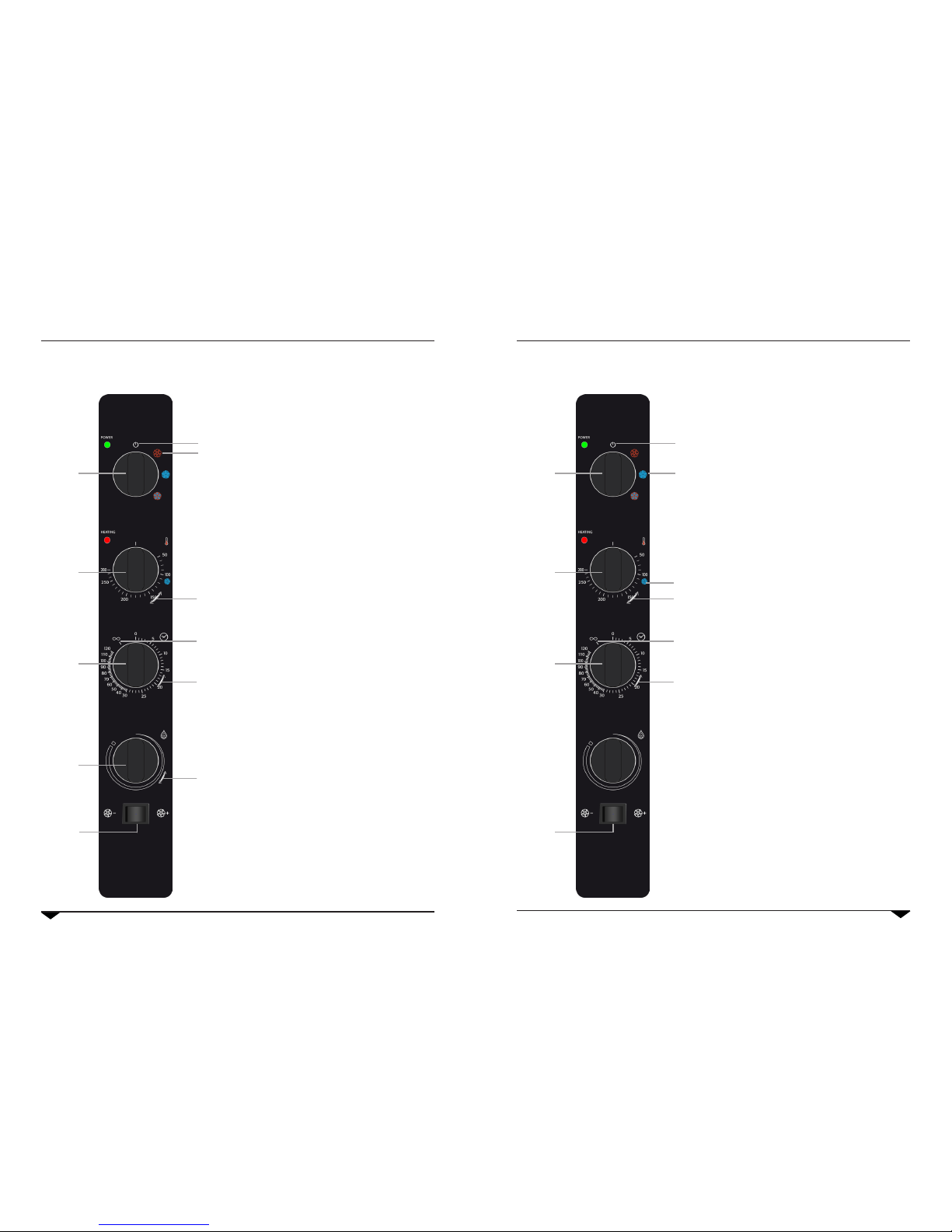
2.3 Convection cooking
Choose the convection cooking mode by turning the
M1 knob clockwise to position I2.
Then choose the cooking temperature by turning the
M2 knob to the desired temperature.
Set the cooking time by turning the M3 knob. Place
the knob indicator on the I6 symbol to avoid the
timer. When the timer set will be over the oven will
buzz and turn off itself.
Set the fan speed using the button T1.
2. Use instruction (combi-ovens)
I 1
I 2
S 1
S 2
S 3
M 1
M 2
M 3
M 4
I 6
T 1
Choose steaming mode by turning the M1 knob to
clockwise to position I3.
Then choose the cooking temperature by turning the
M2 knob to the desired temperature. It is suggested
to set the steaming temperature at 110°C as indica-
ted on the I5 symbol.
Set the cooking time by turning the M3 knob. Place
the knob indicator on the I6 symbol to avoid the
timer. When the timer set will be over the oven will
buzz and turn off itself.
Set the fan spped using the button T1.
2.4 Steaming
2. Use instruction (combi-ovens)
I 1
I 3
I 5
S 1
S 2
M 1
M 2
M 3
I 6
T 1
 Loading...