

Page 1
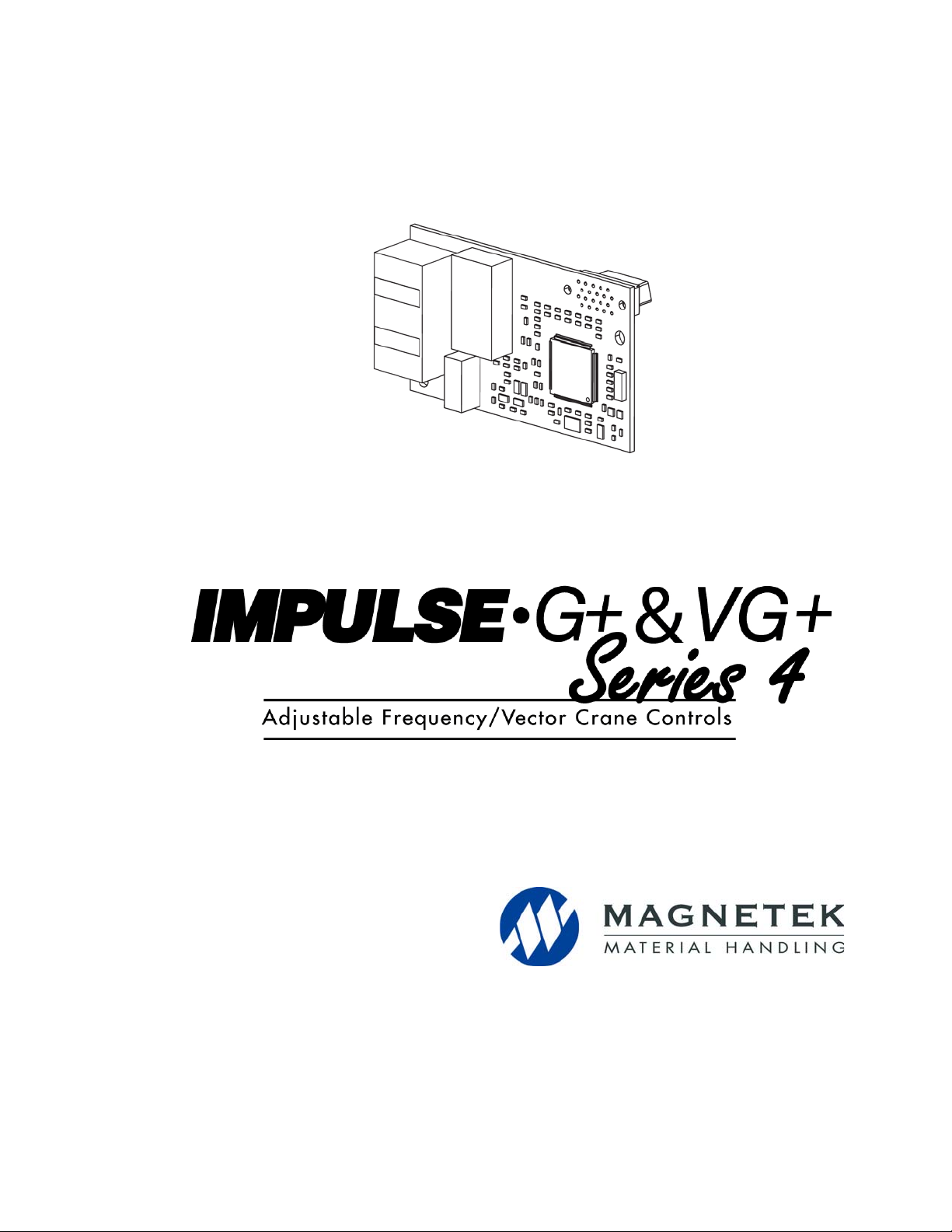
PROFINET Installation Manual
August 2014
Part Number: 144-27019
© Copyright 2014 Magnetek
Page 2

Table of Contents
1. Preface and Safety. . . . . . . . . . . . . . . . . . . . . . . . . . . . . . . . . . . . . . . . . . . . . .4
Applicable Documentation. . . . . . . . . . . . . . . . . . . . . . . . . . . . . . . . . . . . . . . . . . . . . . . . . . . . 4
Terms. . . . . . . . . . . . . . . . . . . . . . . . . . . . . . . . . . . . . . . . . . . . . . . . . . . . . . . . . . . . . . . . . . . . 5
Registered Trademarks. . . . . . . . . . . . . . . . . . . . . . . . . . . . . . . . . . . . . . . . . . . . . . . . . . . . . . 5
Supplemental Safety Instructions . . . . . . . . . . . . . . . . . . . . . . . . . . . . . . . . . . . . . . . . . . . . . . 5
General Safety. . . . . . . . . . . . . . . . . . . . . . . . . . . . . . . . . . . . . . . . . . . . . . . . . . . . . . . . . . . . . 6
2. Product Overview . . . . . . . . . . . . . . . . . . . . . . . . . . . . . . . . . . . . . . . . . . . . . .7
About This Product . . . . . . . . . . . . . . . . . . . . . . . . . . . . . . . . . . . . . . . . . . . . . . . . . . . . . . . . . 7
3. Receiving . . . . . . . . . . . . . . . . . . . . . . . . . . . . . . . . . . . . . . . . . . . . . . . . . . . . .8
Option Package Contents . . . . . . . . . . . . . . . . . . . . . . . . . . . . . . . . . . . . . . . . . . . . . . . . . . . . 8
Tools Required for Installation . . . . . . . . . . . . . . . . . . . . . . . . . . . . . . . . . . . . . . . . . . . . . . . . . 8
4. Option Components . . . . . . . . . . . . . . . . . . . . . . . . . . . . . . . . . . . . . . . . . . . .9
SI-EP3 PROFINET Option . . . . . . . . . . . . . . . . . . . . . . . . . . . . . . . . . . . . . . . . . . . . . . . . . . . 9
Terminal CN1. . . . . . . . . . . . . . . . . . . . . . . . . . . . . . . . . . . . . . . . . . . . . . . . . . . . . . . . . . . . . . 9
Option LED Display . . . . . . . . . . . . . . . . . . . . . . . . . . . . . . . . . . . . . . . . . . . . . . . . . . . . . . . . 10
Power-Up Diagnostics. . . . . . . . . . . . . . . . . . . . . . . . . . . . . . . . . . . . . . . . . . . . . . . . . . . . . . .11
5. Installation Procedure. . . . . . . . . . . . . . . . . . . . . . . . . . . . . . . . . . . . . . . . . .12
Section Safety . . . . . . . . . . . . . . . . . . . . . . . . . . . . . . . . . . . . . . . . . . . . . . . . . . . . . . . . . . . . 12
Prior to Installing the Option . . . . . . . . . . . . . . . . . . . . . . . . . . . . . . . . . . . . . . . . . . . . . . . . . 14
Installing the Option. . . . . . . . . . . . . . . . . . . . . . . . . . . . . . . . . . . . . . . . . . . . . . . . . . . . . . . . 15
GSD/GSDML Files . . . . . . . . . . . . . . . . . . . . . . . . . . . . . . . . . . . . . . . . . . . . . . . . . . . . . . . . 20
6. Option Related Drive Parameters. . . . . . . . . . . . . . . . . . . . . . . . . . . . . . . . .21
7. PROFINET Messaging. . . . . . . . . . . . . . . . . . . . . . . . . . . . . . . . . . . . . . . . . .25
PROFINET Overview . . . . . . . . . . . . . . . . . . . . . . . . . . . . . . . . . . . . . . . . . . . . . . . . . . . . . . 25
PROFIdrive Communication Profile. . . . . . . . . . . . . . . . . . . . . . . . . . . . . . . . . . . . . . . . . . . . 25
Magnetek-Specific Control and Status Words . . . . . . . . . . . . . . . . . . . . . . . . . . . . . . . . . . . . 28
8. Communication . . . . . . . . . . . . . . . . . . . . . . . . . . . . . . . . . . . . . . . . . . . . . . .29
Introduction to PROFINET IO . . . . . . . . . . . . . . . . . . . . . . . . . . . . . . . . . . . . . . . . . . . . . . . . 29
PROFINET IO in SI-EP3 . . . . . . . . . . . . . . . . . . . . . . . . . . . . . . . . . . . . . . . . . . . . . . . . . . . . 29
Option High Priority Alarm Codes . . . . . . . . . . . . . . . . . . . . . . . . . . . . . . . . . . . . . . . . . . . . . 41
Option Low Priority Alarm Codes. . . . . . . . . . . . . . . . . . . . . . . . . . . . . . . . . . . . . . . . . . . . . . 43
Identification and Maintenance Functions (I&M) . . . . . . . . . . . . . . . . . . . . . . . . . . . . . . . . . . 44
Diagnostic and Alarms. . . . . . . . . . . . . . . . . . . . . . . . . . . . . . . . . . . . . . . . . . . . . . . . . . . . . . 44
Alarm Mechanism . . . . . . . . . . . . . . . . . . . . . . . . . . . . . . . . . . . . . . . . . . . . . . . . . . . . . . . . . 45
9. Web Interface. . . . . . . . . . . . . . . . . . . . . . . . . . . . . . . . . . . . . . . . . . . . . . . . .46
Main Tab . . . . . . . . . . . . . . . . . . . . . . . . . . . . . . . . . . . . . . . . . . . . . . . . . . . . . . . . . . . . . . . . 46
IMPULSE®•G+/VG+ Series 4 Profinet Installation Manual - August 2014
2
Page 3

Drive Status Tab. . . . . . . . . . . . . . . . . . . . . . . . . . . . . . . . . . . . . . . . . . . . . . . . . . . . . . . . . . . 47
Network Tab . . . . . . . . . . . . . . . . . . . . . . . . . . . . . . . . . . . . . . . . . . . . . . . . . . . . . . . . . . . . . . 48
Doc Links Tab. . . . . . . . . . . . . . . . . . . . . . . . . . . . . . . . . . . . . . . . . . . . . . . . . . . . . . . . . . . . . 49
Email Alerts Tab . . . . . . . . . . . . . . . . . . . . . . . . . . . . . . . . . . . . . . . . . . . . . . . . . . . . . . . . . . . 50
10. Troubleshooting . . . . . . . . . . . . . . . . . . . . . . . . . . . . . . . . . . . . . . . . . . . . . 55
Drive-Side Error Codes . . . . . . . . . . . . . . . . . . . . . . . . . . . . . . . . . . . . . . . . . . . . . . . . . . . . . 55
11. Specifications . . . . . . . . . . . . . . . . . . . . . . . . . . . . . . . . . . . . . . . . . . . . . . . 60
IMPULSE®•G+/VG+ Series 4 Profinet Installation Manual - August 2014
3
Page 4
1. Preface and Safety
Magnetek manufactures products used as components in a wide variety of industrial systems and
equipment. The selection and application of Magnetek products remain the responsibility of the
equipment manufacturer or end user. Magnetek accepts no responsibility for the way its products are
incorporated into the final system design. Under no circumstances should any Magnetek product be
incorporated into any product or design as the exclusive or sole safety control. Without exception, all
controls should be designed to detect faults dynamically and fail safely under all circumstances. All
systems or equipment designed to incorporate a product manufactured by Magnetek must be
supplied to the end user with appropriate warnings and instructions as to the safe use an d operation
of that part. Any warnings provided by Magnetek must be promptly provided to the end user.
Magnetek offers an express warranty only as to the quality of it s product s in conforming to st andards
and specifications published in the Magnetek manual. NO OTHER WARRANTY, EXPRESS OR
IMPLIED, IS OFFERED. Magnetek assumes no liability for any personal injury, property damage,
losses, or claims arising from misapplication of its products.
Applicable Documentation
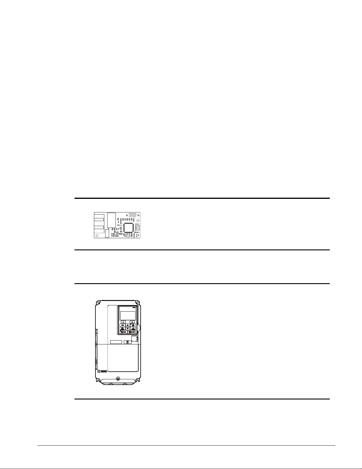
The following manuals are available for the SI-EP3 option:
Option
IMPULSE
Option SI-EP3 PROFINET
Installation Manual
Manual No: 144-27019
®
•G+/VG+ Series 4
Read this manual first.
The installation manual is
packaged with the option and
contains detailed information
about the option, information
required to install the option and
set up related drive parameters.
MPULSE®•G+/VG+ Series 4 Drive
IMPULSE
Instruction Manual
®
•G+/VG+ Series 4
The drive manuals cover basic
installation, wiring, operation
procedures, functions, troubleshooting,
and maintenance information. The
manuals also include important
information about parameter settings
and drive tuning.
Access http://www.magnetek.com to
obtain Magnetek instruction manuals.
IMPULSE®•G+/VG+ Series 4 Profinet Installation Manual - August 2014
4
Page 5

Terms
DANGER
DANGER indicates an imminently hazardous situation which, if not avoided, will result in
death or serious injury. This signal word is to be limited to the most extreme situations.
WA R NI N G
WARNING indicates a potentially hazardous situa tion which, if not avoided, could resu lt in
death or serious injury.
CAUTION
CAUTION indicates a potentially hazardous situation which, if not avoided, could result in
minor or moderate injury. It may also be used to alert against unsafe practices.
NOTICE
NOTICE indicates an equipment damage message.
Drive: IMPULSE®•G+/VG+ Series 4
Option: IMPULSE
®
•G+/VG+ Series 4 SI-EP3 PROFINET option
Registered Trademarks
• All trademarks are the property of their respective owners.
Supplemental Safety Instructions
Read and understand this manual before installing, operating, or servicing this option. The option
must be installed according to this manual and local codes.
The following conventions are used to indicate safety messages in this manual. Failure to heed
these messages could result in serious or possibly even fatal injury or damage to the products or to
related equipment and systems.
NOTE: A NOTE statement is used to notify installation, operation, programming, or maintenance
information that is important, but not hazard-related.
IMPULSE®•G+/VG+ Series 4 Profinet Installation Manual - August 2014
5
Page 6
General Safety
DANGER
Heed the safety messages in this manual.
Failure to comply will result in death or serious injury.
The operating company is responsible for any injuries or equipment damage resulting
from failure to heed the warnings in this manual.
NOTICE
Do not modify the drive or option circuitry.
Failure to comply could result in damage to the drive or option and will void the warranty.
Magnetek is not responsible for any modification of the product made by the user. This
product must not be modified.
Do not expose the drive to halogen group disinfectants.
Failure to comply may cause damage to the electrical components in the option.
Do not pack the drive in wooden materials that have been fumigated or sterilized.
Do not sterilize the entire package after the product is packed.
General Precautions
• The diagrams in this section may include options and drives without covers or safety shields to
illustrate details. Be sure to reinstall covers or shields before operating any devices. The option
should be used according to the instructions described in this manual.
• Any illustrations, photographs, or examples used in this manual are provided as examples only
and may not apply to all products to which this manual is applicable.
• The products and specifications described in this manual or the content and presentation of the
manual may be changed without notice to improve the product and/or the manual.
• When ordering new copies of the manual, cont act your Magnetek representative and provide the
manual number shown on the front cover.
IMPULSE®•G+/VG+ Series 4 Profinet Installation Manual - August 2014
6
Page 7

2. Product Overview
About This Product
The PROFINET SI-EP3 option connects the Series 4 drive to a PROFINET network and facilitates
the exchange of data.
This manual explains the handling, installation, and specifications of this product.
The PROFINET SI-EP3 option is a simple networking solution that reduces the cost and time to wire
and install factory automation devices, while providing interchangeability of like components from
multiple vendors.
By installing the option to a drive, it is possible to do the following from a PROFINET master device:
• operate the drive,
• monitor the operation status of the drive, and/or
• change parameter settings.
SI-EP3 is PROFINET Conformance Class A certified.
IMPULSE®•G+/VG+ Series 4 Profinet Installation Manual - August 2014
7
Page 8
3. Receiving
Please perform the following tasks upon receiving the option:
• Inspect the option for damage. Contact the shipper immediately if the option appears damaged
upon receipt.
• Verify receipt of the correct model by checking the model number printed on the option
nameplate.
• Contact your supplier if you have received the wrong model or the option does not function
properly.
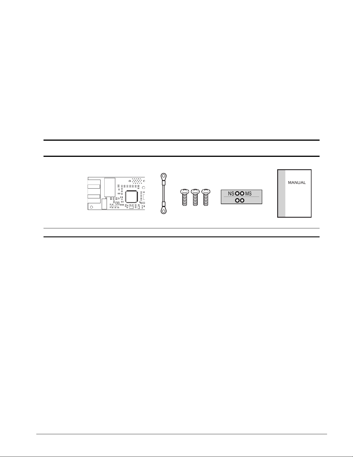
Option Package Contents
Description Option
--
Quantity 1 1 3 1 1
Ground
Wire
Screws (M3) LED Label Installation Manual
Tools Required for Installation
• A Phillips screwdriver (M3 metric/#1, #2 U.S. standard size*) is required to install the option and
remove drive front cove rs.
• Diagonal cutting pliers (required for some drive models).
• A small file or medium grit sandpaper ( required for some drive models).
*Screw sizes vary by drive capacity. Select a screwdriver appropriate for the drive capacity.
NOTE: Tools required to prepare option cables for wiring are not listed in this manual.
IMPULSE®•G+/VG+ Series 4 Profinet Installation Manual - August 2014
8
Page 9
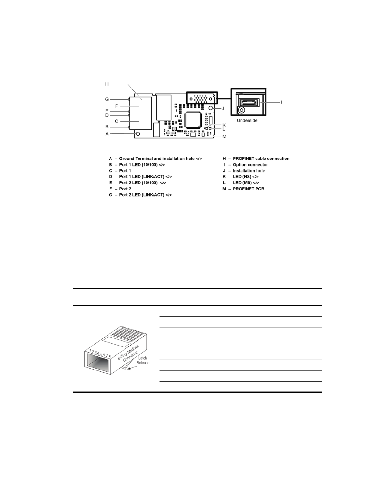
4. Option Components
SI-EP3 PROFINET Option
<1> The ground wire provided in the option shipping package must be connected during installation.
<2> Refer to Option LED Display on page 10 for details on the LEDs.
Figure 1: Option (Top View)
Terminal CN1
The communication connector on the option is a modular RJ45 female connector designated CN1.
CN1 is the connection point for a customer-supplied male Ethernet network communication cable.
Table 1: Male 8-way Ethernet Modular Connector (Customer-Supplied)
Male EtherNet 8-Way Modular
Connector
<1> Not used for 10 Mbps and 100 Mbps networks.
Pin Description
1 (Pair 2) Transmit data (TXD) +
2 (Pair 2) Transmit data (TXD) 3 (Pair 3) Receive data (RXD) +
4 (Pair 1) Not used <1>
5 (Pair 1) Not used <1>
6 (Pair 3) Receive data (RXD) 7 (Pair 4) Not used <1>
8 (Pair 4) Not used <1>
IMPULSE®•G+/VG+ Series 4 Profinet Installation Manual - August 2014
9
Page 10

Option LED Display
The option has six LEDs:
Bi-color Status LEDs:
• Module status (MS) red/green
• Network status (NS) red/green
PROFINET LEDs (2 each):
• Network speed-10/100 yellow
• Link status and network activity-Link/Act green
The operational states of the option LEDs after th e power-up diagnostic LED sequence is completed
are described in Table 2: Option LED States. Th e states with a number in parenthesis are the
number of pulses of 250 ms on, 250 ms off cycles, followed by 500 ms off, then repeating the cycle.
Wait at least two seconds for the power-up diagnostic process to complete before verifying LED
states.
Table 2: Option LED States
Name
MS (visible through
drive cover)
NS (visible through
drive cover)
10/100 (visible at
RJ45 jack)
LINK/ACT (visible at
RJ45 jack)
Indication
Operating Status Remarks
Color Status
-- OFF Power Supply OFF Power is not being supplied to the drive.
Green ON Option operating
Green Flashing (1) Diagnostics Diagnostic data available.
Green Flashing (2) Configuration tool Identified by a configuration tool.
Red ON Default MAC or fatal error occurred
Red Flashing (1) Configurational error (non-fatal) Configuration error.
Red Flashing (2) No IP (non-fatal) No IP address assigned.
Red Flashing (3) No station name (non-fatal) No station name assigned.
Red Flashing (4) Init failure (non-fatal) Failed to initialize module.
Green/
Red
-- OFF Offline or Power supply OFF -Green ON Connected
Green Flashing Connected and stopped
Red ON BUS fault Unrecoverable BUS fault.
Red Flashing (1) Lost communication Host communication is temporarily lost.
Red Flashing (2) Lost link No link detected to network.
Yellow OFF 10 Mbps is established -Yellow ON 100 Mbps is established -Green OFF Link is not established -Green ON Link is established --
Green Flashing
Flashing Option self-test The option is in self-test mode.
Link is established and there is
network activity
The option is operating normally and initialization
is complete.
Default MAC address has been programmed or
the option has detected an unrecoverable error.
Connection established with I/O controller and in
RUN mode.
Connection established with I/O controller and in
STOP mode.
--
IMPULSE®•G+/VG+ Series 4 Profinet Installation Manual - August 2014
10
Page 11

Power-Up Diagnostics
An LED test is performed each time the drive is powered up. The initial boot sequence may take
several seconds. After the LEDs have completed the diagnostic LED sequence, as shown in Table 3:
Power-Up Diagnostic LED Sequence, the option is successfully initialized. The LEDs then assume
operational conditions as shown in Table 2: Option LED States.
Table 3: Power-Up Diagnostic LED Sequence
Sequence Module Status (MS) Network Status (NS) Time (ms)
1 Green OFF 250
2 Red OFF 250
3 Green OFF -4 Green Green 250
5 Green Red 250
6 Green OFF --
IMPULSE®•G+/VG+ Series 4 Profinet Installation Manual - August 2014
11
Page 12
5. Installation Procedure
DANGER
Electric Shock Hazard
Do not connect or disconnect wiring while the power is on.
Failure to comply will result in death or serious injury.
Disconnect all power to the drive, wait at least five minutes after all indicators are off,
measure the DC bus voltage to confirm safe level, and check for unsafe voltages before
servicing. The internal capacitor remains charged after the power supply is turned off.
The charge indicator LED will extinguish when the DC bus voltage is below 50 VDC.
WARNING
Electrical Shock Hazard
Do not remove the option cover while the power is on.
Failure to comply could result in death or serious injury.
The diagrams in this section may include options and drives without covers or safety
shields to show details. Be sure to reinstall covers or shields before operating any
devices. Use the option according to the instructions described in this manual.
Do not allow unqualified personnel to use equipment.
Failure to comply could result in death or serious injury.
Maintenance, inspection, and replacement of parts must be performed only by
authorized personnel familiar with installation, adjustment, and maintenance of this
product.
Do not touch circuit boards while the power to the dr ive is on.
Failure to comply could result in death or serious injury.
Do not use damaged wires, stress the wiring, or damage the wire insulation.
Failure to comply could result in death or serious injury.
Fire Hazard
Tighten all terminal screws to the specified tightening torque.
Loose electrical connections could result in death or serious injury by fire due to
overheating of electrical connections.
Section Safety
IMPULSE®•G+/VG+ Series 4 Profinet Installation Manual - August 2014
12
Page 13

NOTICE
Damage to Equipment
Observe proper electrostatic discharge (ESD) procedures when handling the option,
drive, and circuit boards.
Failure to comply may result in ESD damage to circuitry.
Never shut the power off while the drive is running or outputting voltage.
Failure to comply may cause the application to operate incorrectly or damage the drive.
Do not operate damaged equipment.
Failure to comply may cause further damage to the equipment.
Do not connect or operate any equipment with visible damage or missing parts.
Do not use unshielded cable for control wiring.
Failure to comply may cause electrical interference resulting in poor system
performance.
Use shielded twisted-pair wires and ground the shield to the ground terminal of the
drive.
Properly connect all pins and connectors.
Failure to comply may prevent proper operation and possibly damage equipment.
Check wiring to ensure that all connections are correct after installing the option and
connecting any other devices.
Failure to comply may result in damage to the option.
IMPULSE®•G+/VG+ Series 4 Profinet Installation Manual - August 2014
13
Page 14
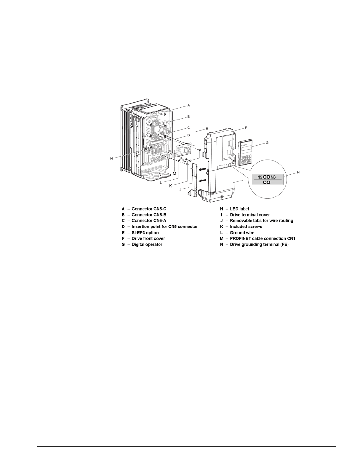
Prior to Installing the Option
Prior to installing the option, wire the drive, make necessary connections to the drive terminals, and
verify that the drive functions normally without the option installed. Refer to the Instruction Manual
packaged with the drive for information on wiring and connecting the drive.
Figure 2 shows an exploded view of the drive with the option and related components for refere nce.
Figure 2: Drive Components with Options
IMPULSE®•G+/VG+ Series 4 Profinet Installation Manual - August 2014
14
Page 15

Installing the Option
DANGER
Electrical Shock Hazard.
Do not connect or disconnect wiring while the power is on. Failure to comply will result in
death or serious injury . Before installing the option, disconnect all power to the drive. The
internal capacitor remains charged eve n after the power supply is turned off. The charge
indicator LED will extinguish when the DC bus voltage is below 50 VDC. To prevent
electric shock, wait at least five minutes after all indicators are off and measure the DC
bus voltage level to confirm safe level.
NOTICE
Damage to Equipment
Observe proper electrostatic discharge procedures (ESD) when handling the option,
drive, and circuit boards. Failure to comply may result in ESD damage to circuitry.
Remove the front covers of the drive before installing the option. Refer to the Instruction Manual for
directions on removing the front covers. Cover removal varies depending on drive size. This option
can be inserted only into the CN5-A connector located on the drive control board.
1. Shut off power to the drive, wait the appropriate amount of time for voltage to dissipate, then
remove the digital operator (G) and front covers (F, I). Front cover removal varies by model.
Figure 3: Remove the Front Covers and Digital Operator
IMPULSE®•G+/VG+ Series 4 Profinet Installation Manual - August 2014
15
Page 16
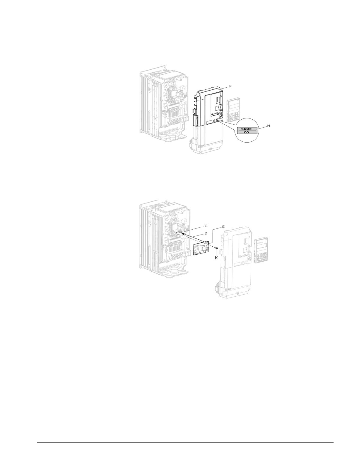
2. With the front covers and digital operator removed, apply the LED label (H) in the appropriate
position on the drive top front cover (F).
Figure 4: Apply the LED Label
3. Insert the option (E) into the CN5-A connector (C) located on the drive and fasten it using one of
the included screws (K).
Figure 5: Insert the Option
IMPULSE®•G+/VG+ Series 4 Profinet Installation Manual - August 2014
16
Page 17
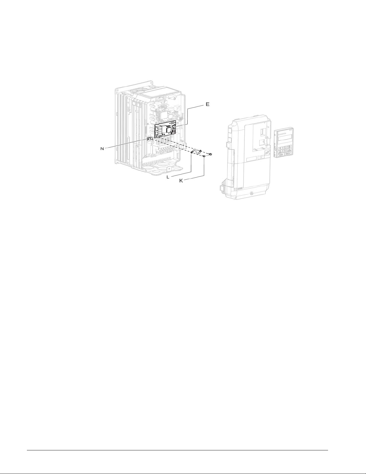
4. Connect the ground wire (L) to the ground terminal (N) using one of the remaining provided
screws (K). Connect the other end of the ground wire (L) to the remaining ground terminal and
installation hole on the option (E) using the last remaining provided screw (K) and tighten both
screws to 0.5 ~ 0.6 nm (4.4 ~ 5.3 in lb.).
Figure 6: Connect the Ground Wire
NOTE: There are two screw holes on the drive for use as ground terminals. When connecting
three options, two ground wires will need to share the same drive ground terminal.
IMPULSE®•G+/VG+ Series 4 Profinet Installation Manual - August 2014
17
Page 18
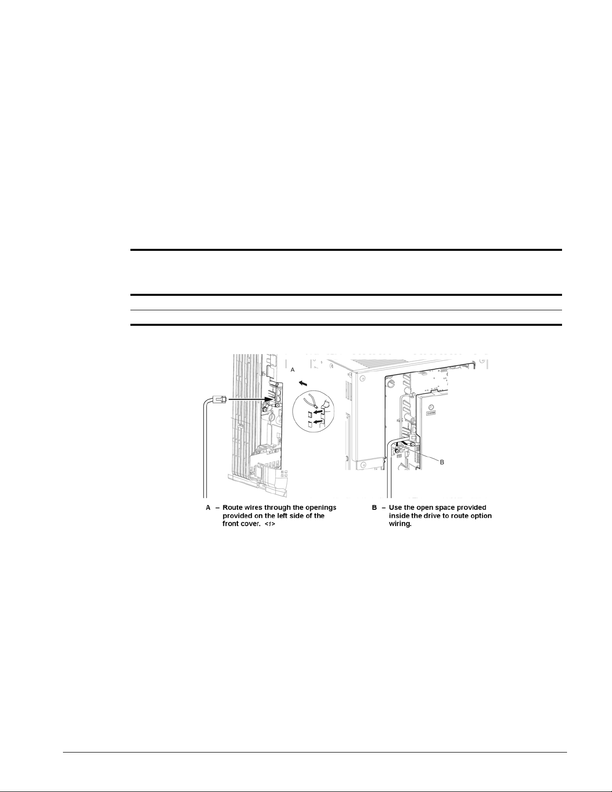
Wiring the Option
5. Route the option wiring.
Depending on the drive model, some drives may require routing the wiring through the side of the
front cover to the outside to provide adequate space for the wiring. In these cases, using diagonal
cutting pliers, cut out the perforated openings on the left side of the drive front cover. Sharp edges
along the cut out should be smoothed down with a file or sand paper to prevent any damage to the
wires.
5.a. Route the PROFINET CAT5e cable inside the enclosure for drives that do not require routing
through the front cover. Refer to Table 4: Mode l-Specific Cable Routing and Figure 7 to determine
the proper wire routing by drive model.
Table 4: Model-Specific Cable Routing
Wire Routing <1>
Drive Series Model
G+/VG+ S4 2003 to 2033; 4001 to 4018; 5001 to 5009 Figure 7 (A) -G+/VG+ S4 2047 and above; 4024 and above; 5012 and above -- Figure 7 (B)
Through Front
Cover
Inside Drive
<1> The drive will not meet NEMA Type 1 requirements if wiring is exposed outside the enclosure.
Figure 7: Wire Routing Examples
6. Connect the PROFINET CAT5e communication cable to the option connector (CN1) port 1.
To connect the option to a network, firmly connect RJ45 8-pin Shielded Twisted Pair CAT5e cable(s)
into the modular connector ports (see Figure 7).
NOTE: Do not connect or disconnect the communication cable while the drive is powered up or
while the drive is in operation. Failure to comply may cause a static discharge, which will
cause the option card to stop working properly. Cycle power on the drive and option card
to reestablish functionality.
IMPULSE®•G+/VG+ Series 4 Profinet Installation Manual - August 2014
18
Page 19
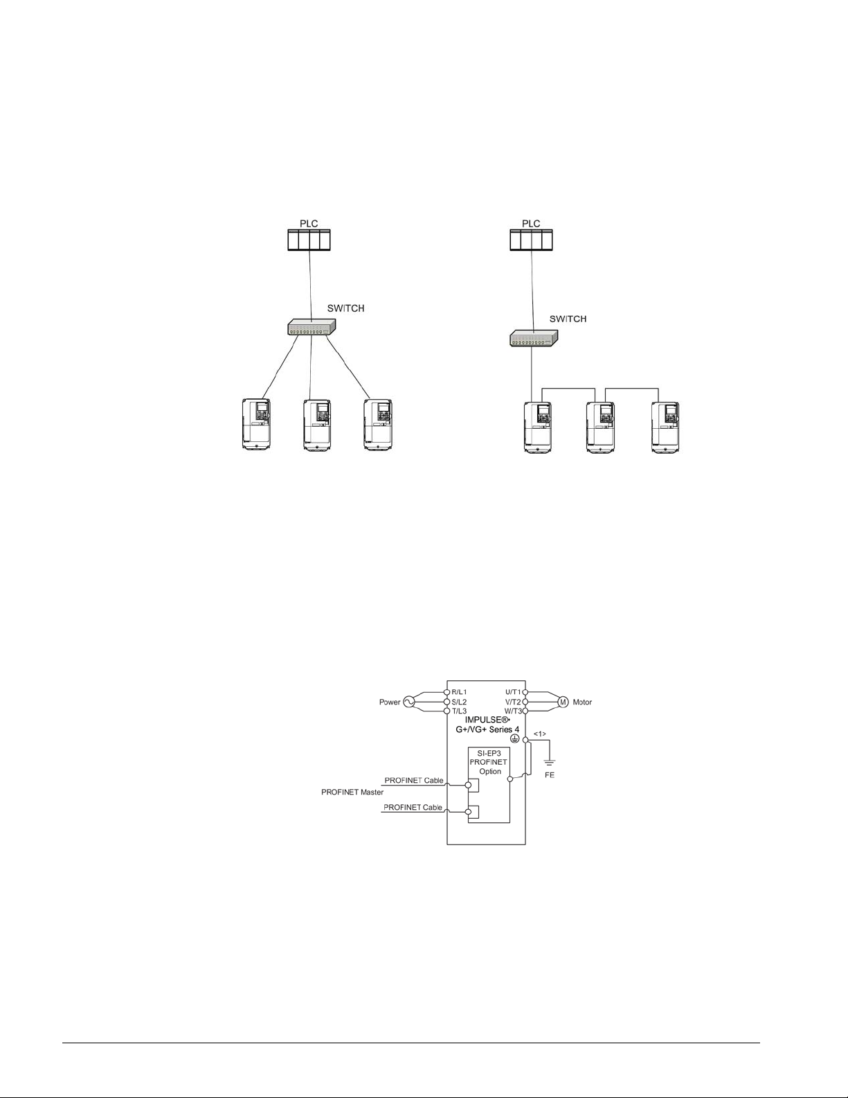
Communication Cable Wiring
The dual RJ45 network ports on the option board act as a switch to allow for flexibility in cabling
topology. For example, a traditional star network topology may be employed by using a single port
on the option board. Alternatively, a daisy-chained approach may be employed by using both RJ45
ports. This second approach reduces the requirements of central switch ports.
Figure 8: Topology Options
Communication Cable Specifications
Only use cables recommended for PROFINET. Using a cable not specifically recommended may
cause the option or drive to malfunction.
The use of CAT5e or equivalent Shielded Twisted Pair (STP) cable is recommended.
7. Use the second communication cable port to daisy chain a series of drives where applicable.
Connection Diagram
<1> The ground wire provided in the option shipping package must be connected during installation.
Figure 9: Wiring Diagram
IMPULSE®•G+/VG+ Series 4 Profinet Installation Manual - August 2014
19
Page 20
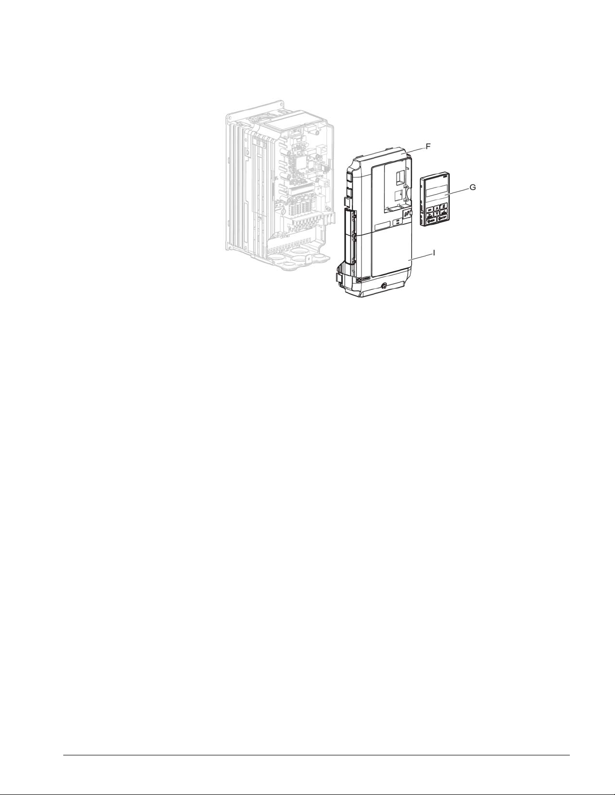
8. Replace and secure the front covers of the drive (F, I) and replace the digital operator (G).
Figure 10: Replace the Front Covers and Digital Operator
NOTE: Take proper precautions when wiring the option so that the front covers will easily fit back
onto the drive. Make sure no cables are pinched between the front covers and the drive
when replacing the covers.
9. Set drive parameters in Table 5: Parameter Settings for proper option performance.
GSD/GSDML Files
To facilitate network implementation, obtain a GSDML file from the following website:
http://www.magnetek.com/Series4Accessories
IMPULSE®•G+/VG+ Series 4 Profinet Installation Manual - August 2014
20
Page 21

6. Option Related Drive Parameters
The following parameters are used to set up the drive for ope ration with the Profinet card. Pa rameter
setting instructions can be found in the drive’s Instruction Manual.
Confirm proper setting of the all parameters in Table 5: Parameter Settings before starting network
communications.
Table 5: Parameter Settings
Parameter
Code Display Function Range Initial Value
B03-01
<1>
<1> To start and stop the drive with the option master device using serial communications, set B03-02 to 3. To control the drive frequency
reference via the master device, set B03-01 to 3.
<2> If F06-01 is set to 4: Alarm Only, then the drive will continue to operate when a bUS error or an EF0 fault is detected. Take prop er
safety measures, such as installing an emergency stop switch.
Ref Source 1 Source from where the frequency
reference is generated.
0Operator Digital Operator
1 Terminals Terminals or Analog Input
• S4-IF Interface Card
• S4-I AC Digital Input Option
• S4-IO Digital Input/Output Option
• DI-A3 Digital Input Option (not used for
B03-02)
2 Serial Com Serial communication
• RS485/422 Serial Communications
(R+, R-, S+, S-)
3Option PCB Industrial Communication Option
card (Port CN5-A)
• EtherNet/IP
• Modbus TCP/IP
• PROFINET
• PROFIBUS-DP
4 Pulse Input Pulse input via Terminal RP (H06-
01)
0–4 1 (Set to 3 for
PROFINET)
IMPULSE®•G+/VG+ Series 4 Profinet Installation Manual - August 2014
21
Page 22

Parameter
Code Display Function Range Initial Value
B03-02
<1>
Run Source 1 Source from where the RUN
command is generated.
0–3 1 (Set to 3 for
PROFINET)
0Operator Digital Operator
1 Terminals Terminals
• S4-IF Interface Card
• S4-I AC Digital Input Option
• S4-IO Digital Input/Output Option
• DI-A3 Digital Input Option (not used for
B03-02)
2 Serial Com Serial communication
• RS485/422 Serial Communications
(R+, R-, S+, S-)
3Option PCB Industrial Communication Option
card (Port CN5-A)
• EtherNet/IP
• Modbus TCP/IP
• PROFINET
• PROFIBUS-DP
F06-01 Com Bus Flt Sel Stoppin g me th od at
0–4 1
communication error.
0 Decel to Stop
1 Coast to Stop
2Fast-Stop
3 Use B3-03 Method
4 Alarm Only <2>
F06-02 EF0 Detection Option External Fault 0, 1 0
0 Always Detected
1 Only During Run
F06-03 EF0 Fault Action Option External Fault 0–4 1
0 Decel to Stop
1 Coast to Stop
2Fast-Stop
3 Use B3-03 Method
4 Alarm Only <2>
F06-07 Fref PrioritySel Selects how multi-step speed
0, 1 0
inputs are treated when the
NetRef command is set.
0 Net/Com REF Multi-step reference disabled
1 MultiStep Speed Multi-step reference enabled
F06-08 Com Prm Init Sel Determines whether
0, 1 0
communication-related
parameters (F06-XX and F07-XX)
are reset when the drive is
initialized using A01-05
0 Init Com Prms Communication-related
parameters (F06-XX and F07-XX)
are not reset when the drive is
initialized using A01-05.
1 No Init Com Prms Reset all communication-related
parameters (F06-XX and F07-XX)
when the drive is initialized using
A01-05.
<1> To start and stop the drive with the option master device using serial communications, set B03-02 to 3. To control the drive frequency
reference via the master device, set B03-01 to 3.
<2> If F06-01 is set to 4: Alarm Only, then the drive will continue to operate when a bUS error or an EF0 fault is detected. Take proper
safety measures, such as installing an emergency stop switch.
IMPULSE®•G+/VG+ Series 4 Profinet Installation Manual - August 2014
22
Page 23

Table 6: F7 Parameter Settings
Parameter
Code Display Description Default
F07-01 to
F07-04
F07-05 to
F07-08
F07-09 to
F07-12
F07-13 IP Add Mode Sel Sets how the option card IP address is set at start up 2
F07-14 Duplex Mode Selection Sets how the communication between host/client will
F07-15 Baud Rate Sets the communication speed for the option card. 10
F07-23 to
F07-27
<1>*
F07-33 to
F07-37
<1>*
H05-11 Enter CommandSel 1
<1> If a value other than 0 is assigned to parameters F07-23 to F07-27 and F07-33 to F07-37 by the drive, that value will take precedence
over a value set by the configuration software. If the value in the drive is 0 (default), the value from the configuration software is used.
* Not visible before 14706 firmware.
IP Address Sets static IP address of the SI-EP3 option when
parameter F07-13=0.
NOTE: Parameter F07-01 sets the most
significant octet.
Subnet Mask Sets static Subnet Mask of network connection.
NOTE: Parameter F07-05 sets the most
significant octet.
Gateway Address Sets static Gateway address of network connection.
NOTE: Parameter F07-09 sets the most
significant octet.
0 User Defined
1BOOTP
2 DHCP
be determined.
0 Half Duplex
1 Auto Negotiate
2 Full Duplex
10 10 Mbps
100 100 Mbps
Dynamic Output
Configurable outputs 1 to 5. 0
Assembly Parameters
Dynamic Input
Configurable inputs 1 to 5. 0
Assembly Parameters
0 Enter Required Drive requires an Enter command before accepting
any changes to parameter settings.
1 No EnterRequired Parameter changes are activated immediately
without the Enter command.
192 168 1 20
255 255 255 0
192 168 1 1
1
IMPULSE®•G+/VG+ Series 4 Profinet Installation Manual - August 2014
23
Page 24

Table 7: Option Monitors
Parameter
Code Display Description Value Range
U06-80 to
U06-83
U06-84 to
U06-87
U06-88 to
U06-91
U06-92 Online Speed Port 1 Link Speed 10, 100
U06-93 Online Duplex Port 1 Duplex Setting 0: Half; 1: Full
U06-94 Online Duplex Port 2 Link Speed 0: Half; 1: Full
U06-95 Online Duplex Port 2 Duplex Setting 0: Half; 1: Full
U06-98 First Fault First Option Board Fault -U06-99 Current Fault Current Option Board Fault --
Online IP Address SI-EP3 IP Address, U06-80 is the most significant
0–255
octet.
Online Subnet Subnet, U06-84 is the most significant octet. 0–255
Online Gateway Gateway, U06-88 is the most significant octet. 0–255
IMPULSE®•G+/VG+ Series 4 Profinet Installation Manual - August 2014
24
Page 25

7. PROFINET Messaging
PROFINET Overview
This section describes the communication profile used between the PROFINET I/O network and the
option.
The option supports the PROFIdrive profile. Users can select between the contr ol and status words
according to the PROFIdrive profile or use the Magnetek-specific control and status words.
PROFIdrive Communication Profile
The Control Word and the Status Word
The contents of the Control Word and the Status Word are detailed in Table 8: Control Word for
PROFIdrive Communication Profile and Table 9: Statu s Word for the PROFIdrive Communication
Profile, respectively. The drive states are presented in the PROFIdrive State Machine (Figure 11).
Frequency Reference
The Frequency Reference is a 16-bit word containing a sign bit and a 15-bit integer. A negative
reference (indicating reverse direction of rotation) is formed by calculating the two's complement
from the corresponding positive reference. The reference value is the desired output frequency.
Output Frequency
Output Frequency is a 16-bit word containing the current output frequency (U01-02) of the drive.
Table 8: Control Word for PROFIdrive Communication Profile
Bit Name Value Proceed to STATE/Description
ON 1 Proceed to READY TO OPERATE.
0
1OFF2
2OFF3
3
4 RAMP_OUT_ZERO
5 RAMP_HOLD
OFF1 0
OPERATION_
ENABLE
1 Continue operation (OFF2 inactive).
0
1 Continue operation (OFF3 inactive).
0
1 Proceed to ENABLE OPERATION.
0 In hibit operation. Proceed to OPERATION INHIBIT.
1
0 Stop according to selected stop type.
1 Normal operation.
0
Emergency OFF . Proceed to OFF1 ACTIVE; proceed
further to READY TO SWTICH ON unless other
interlocks (OFF2, OFF3) are active
Emergency OFF . Proceed to OFF2 ACTIVE; proceed
further to SWITCH-ON INHIBIT.
Emergency stop. Proceed to OFF3 ACTIVE; proceed
further to SWITCH-ON INHIBIT.
Normal operation. Proceed to RAMP FUNCTION
GENERATOR: ENABLE OUTPUT.
Proceed to RAMP FUNCTION GENERATOR:
ENABLE ACCELERATOR. Halt ramping (Ramp
Function Generator output held).
IMPULSE®•G+/VG+ Series 4 Profinet Installation Manual - August 2014
25
Page 26

Bit Name Value Proceed to STATE/Description
Normal operation. Proceed to OPERATING.
NOTE: This bit is effective only if the fieldbus
interface is set as the source for this
6 RAMP_IN_ZERO
1
signal by drive parameters.
0 Force Ramp Function Generator input to zero.
Fault reset if an active fault exists. Proceed to
SWITCH ON INHIBIT.
7 RESET
0 -> 1
0 ( Continue normal operation)
8 INCHING_1 -- Inching 1. (Not supported)
9 INCHING_2 -- Inching 2. (Not supported)
10 REMOTE_CMD
1 Network control enabled.
0 Network control disabled.
11 to 15 -- -- Reserved.
Table 9: Status Word for the PROFIdrive Communication Profile
Bit Name Value Proceed to STATE/Description
0 RDY_ON
1 RDY_RUN
2 RDY_RUN
3 TRIPPED
4 OFF_2_STA
5 OFF_3_STA
6 SWC_ON_INHIB
7ALARM
8 AT_SETPOINT
9REMOTE
10 ABOVE_LIMIT -- Not supported.
11 to 15 -- -- Reserved.
1 READY TO SWITCH ON.
0 NOT READY TO SWITCH ON.
1 READY TO OPERATE.
0 OFF1 ACTIVE.
1 ENABLE OPERATION.
0 DISABLE OPERATION.
1FAULT.
0 No fault.
1 OFF2 inactive.
0 OFF2 ACTIVE.
1 OFF3 inactive.
0 OFF3 ACTIVE.
1 SWITCH-ON INHIBIT ACTIVE.
0 S WITCH-ON INHIBIT NOT ACTIVE.
1 Warning/Alarm.
0 No Warning/Alarm.
1
0
OPERATING. Actual value equals reference value
(i.e., is within tolerance limits).
Actual value differs from reference value (i.e., is
outside tolerance limits).
1 Drive control location: REMOTE.
0 Drive control location: LOCAL.
IMPULSE®•G+/VG+ Series 4 Profinet Installation Manual - August 2014
26
Page 27
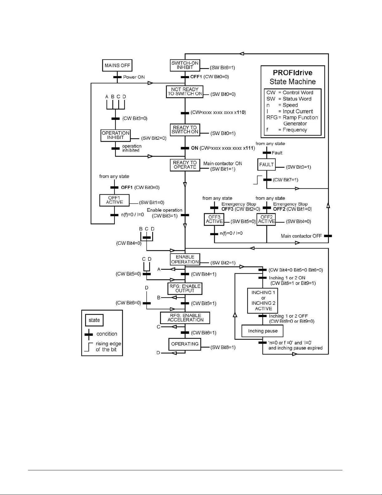
Figure 11: PROFIdrive State Machine
IMPULSE®•G+/VG+ Series 4 Profinet Installation Manual - August 2014
27
Page 28

Magnetek-Specific Control and Status Words
The Control Word and the Status Word
The contents of the Control Word and the Status Word are detailed in Table 10: Magnetek-Specific
Control Word and Status Word.
Frequency Reference
Frequency Reference is a 16-bit word containing the desired output frequency.
Output Frequency
Output Frequency is a 16-bit word containing the current output frequency of the drive.
Table 10: Magnetek-Specific Control Word and Status Word
Magnetek-Specific Control Word Magnetek-Specific Status Word
Bit Description Bit Description
0 Run Bit 0 Running
1 R everse run bit 1 Zero Speed
2 EF0 2 Reverse Operation
3 Fau lt Reset 3 Reset Signal Input Active
4 ComFref 4 At Speed
5 ComCtrl 5 Ready
6DI3 6Alarm
7DI4 7Fault
8DI5 8oPE Fault
9DI6 9Uv Return
10 DI7 10 2nd Motor
11 DI8 11 ZSV
IMPULSE®•G+/VG+ Series 4 Profinet Installation Manual - August 2014
28
Page 29

8. Communication
This section describes the PROFINET IO messaging used in communication with the drive.
For detailed information on PROFINET IO communication, refer to the PROFINET specification
Application Layer protocol for decentralized periphery and distributed automation v2.0 available at
www.profibus.com.
Introduction to PROFINET IO
PROFINET IO is a fieldbus protocol that enables communication between programmable controller s
and distributed field devices in an Ethernet network. The protocol classifies devices into IO
controllers, IO supervisors, and IO devices, which have a specific collection of services.
PROFINET IO uses three different communication ch annels to exchange data. The standard UDP/
IP and TCP/IP channel is used for parameterization and configuration of devices and for acyclic
operations. The Real Time (RT) channel is used for cyclic data transfer and alarms. The third
channel, Isochronous Real Time (IRT) channel, is used e.g. in motion control applications (not
implemented in SI-EP3).
PROFINET IO devices are structured in slots and sub-slots, which can contain modules and submodules correspondingly. Devices can have almost any number of slots and sub-slots and they can
be virtual or real. Device specific data is represented in slot 0; module and sub-module specific da t a
in subsequent slots and sub-slots.
One of the benefits of PROFINET IO is the diagnostics and alarm mechanism. Every module and
sub-module provide alarm data to the IO controller using the cyclic channel. Diagnostic data can be
read non-cyclically from the device by using record data.
Properties and services of a PROFINET IO device are described in a GSD file that is written in
General St ation Description Markup L anguage (GSDML). The GSD file describes the device specific
modules and the method of assigning modules and sub-modules to predefined slots and sub-slots.
PROFINET IO in SI-EP3
The decision to use either the PROFIdrive control and st atus words or the Mag netek-specific control
and status words is done in a hardware configuration tool (customer-supplied). The default value is
the Magnetek-specific format.
SI-EP3 uses slots 0 and 1. Slot 0 does not have any sub-slots and the attached de vice access poin t
(DAP) module represents the device. Other functional modules and sub-modules described in the
GSD file can be assigned to slot 1 and its sub-slots.
• Slot 0 = Device access point (DAP)
• Slot 1, sub-slot 1 = Standard telegram 1, Standard telegram 1 + 5 configurable inputs, outputs,
Forty byte IO with 5 configurable input, outputs
The services provided by the SI-EP3 option can be defined using the F07-XX par ameters in the drive
or by using a configuration tool. To define the service using the F07-XX parameters, set the
parameter to a value other than 0.
If all F07-XX parameters are set to 0, the value from the configuration tool will be used.
The SI-EP3 option provides the following services:
• Cyclic messaging in PROFIdrive or Magnetek-specific mode
• Acyclic parameter access mechanism
• Identification & Maintenance functions (I&M0)
• PROFIdrive parameters
IMPULSE®•G+/VG+ Series 4 Profinet Installation Manual - August 2014
29
Page 30

• Diagnostic and alarm mechanism
• Fault buffer mechanism
Magnetek SI-EP3 PROFINET I/O Modules
Std Tgm 1
Table 11: Std Tgm 1 Consume
Bytes Description
0 Control Word MSB
1 Control Word LSB
2 Frequency Reference MSB
3 Frequency Reference LSB
Table 12: Std Tgm 1 Produce
Bytes Description
0 Status Word MSB
1 Status Word LSB
2 Output Frequency MSB
3 Output Frequency LSB
Std Tgm 1 + 5 PZD
Table 13: Std Tgm 1 + 5 PZD Consume
Bytes Description
0 Control Word MSB
1 Control Word LSB
2 Frequency Reference MSB
3 Frequency Reference LSB
4 Configurable Output 1 MSB
5 Configurable Output 1 LSB
6 Configurable Output 2 MSB
7 Configurable Output 2 LSB
8 Configurable Output 3 MSB
9 Configurable Output 3 LSB
10 Configurable Output 4 MSB
11 Configurable Output 4 LSB
12 Configurable Output 5 MSB
13 Configurable Output 5 LSB
IMPULSE®•G+/VG+ Series 4 Profinet Installation Manual - August 2014
30
Page 31

Forty Byte IO
Table 14: Std Tgm 1 + 5 PZD Produce
Bytes Description
0 Status Word MSB
1 Status Word LSB
2 Output Frequency MSB
3 Output Frequency LSB
4 Configurable Input 1 MSB
5 Configurable Input 1 LSB
6 Configurable Input 2 MSB
7 Configurable Input 2 LSB
8 Configurable Input 3 MSB
9 Configurable Input 3 LSB
10 Configurable Input 4 MSB
11 Configurable Input 4 LSB
12 Configurable Input 5 MSB
13 Configurable Input 5 LSB
Table 15: Forty Byte IO Consume
Bytes Description
0 Control Word MSB
1 Control Word LSB
2 Frequency Reference MSB
3 Frequency Reference LSB
4 Torque Reference MSB
5 Torque Reference LSB
6 Torque Compensation MSB
7 Torque Compensation LSB
8 Reserved
9 Reserved
10 Reserved
11 Reserved
12 Analog Output 1 MSB
13 Analog Output 1 LSB
14 Analog Output 2 MSB
15 Analog Output 2 LSB
16 Digital Outputs MSB
17 Digital Outputs LSB
18 Reserved
19 Reserved
20 Reserved
21 Reserved
22 Reserved
23 Reserved
24 Reserved
25 Reserved
IMPULSE®•G+/VG+ Series 4 Profinet Installation Manual - August 2014
31
Page 32

Bytes Description
26 Reserved
27 Reserved
28 Reserved
29 Reserved
30 Configurable Output 1 MSB
31 Configurable Output 1 LSB
32 Configurable Output 2 MSB
33 Configurable Output 2 LSB
34 Configurable Output 3 MSB
35 Configurable Output 3 LSB
36 Configurable Output 4 MSB
37 Configurable Output 4 LSB
38 Configurable Output 5 MSB
39 Configurable Output 5 LSB
Table 16: Forty Byte IO Produce
Bytes Description
0 Status Word MSB
1 Status Word LSB
2 Output Frequency MSB
3 Output Frequency LSB
4 Torque Reference MSB
5 Torque Reference LSB
6 PG Count Value MSB
7 PG Count Value LSB
8 Motor Speed MSB
9 Motor Speed LSB
10 Frequency Reference Monitor MSB
11 Frequency Reference Monitor LSB
12 Output Current MSB
13 Output Current LSB
14 Analog Input 1 MSB
15 Analog Input 1 LSB
16 DC Bus Voltage MSB
17 DC Bus Voltage LSB
18 Fault Code MSB
19 Fault Code LSB
20 Alarm Code MSB
21 Alarm Code LSB
22 Output Power MSB
23 Output Power LSB
24 Analog Input 2 MSB
25 Analog Input 2 LSB
26 Digital Inputs MSB
27 Digital Inputs LSB
IMPULSE®•G+/VG+ Series 4 Profinet Installation Manual - August 2014
32
Page 33
Bytes Description
28 Analog Input 3 MSB
29 Analog Input 3 LSB
30 Configurable Input 1 MSB
31 Configurable Input 1 LSB
32 Configurable Input 2 MSB
33 Configurable Input 2 LSB
34 Configurable Input 3 MSB
35 Configurable Input 3 LSB
36 Configurable Input 4 MSB
37 Configurable Input 4 LSB
38 Configurable Input 5 MSB
39 Configurable Input 5 LSB
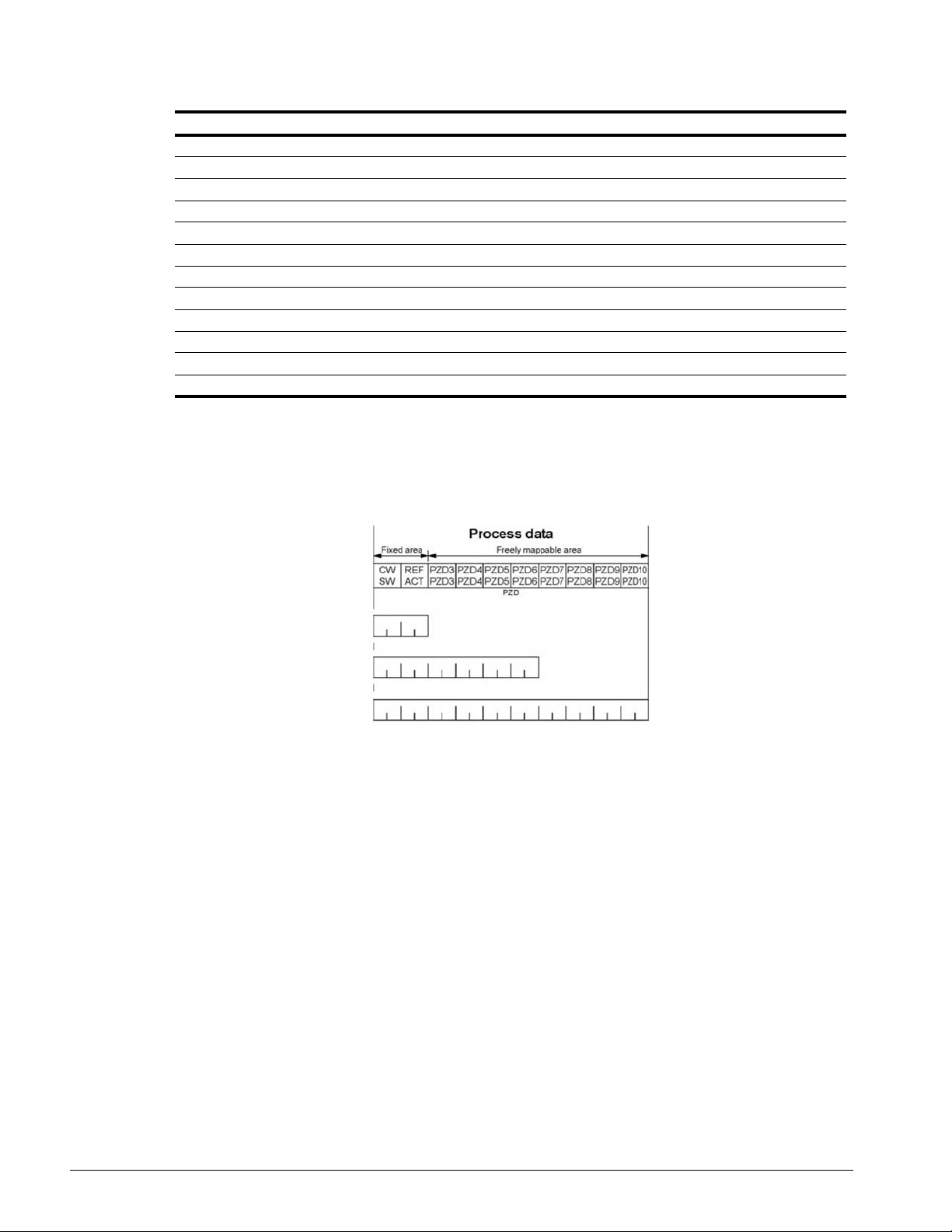
Cyclic Messaging
SI-EP3 supports cycle times of 8 to 512 ms.
CW: Control Word
SW: Status Word
REF: Reference
ACT: Actual Value
PZD: Configurable inputs and outputs
Magnetek Acyclic Parameter Access Mechanism
All drive parameters can be read and written under address 0x8000 by performing a read or write
with the index value of the corresponding parameter address in the drive. Refer to the Series 4
Instruction Manual for a list of these parameter addresse s.
IMPULSE®•G+/VG+ Series 4 Profinet Installation Manual - August 2014
33
Page 34
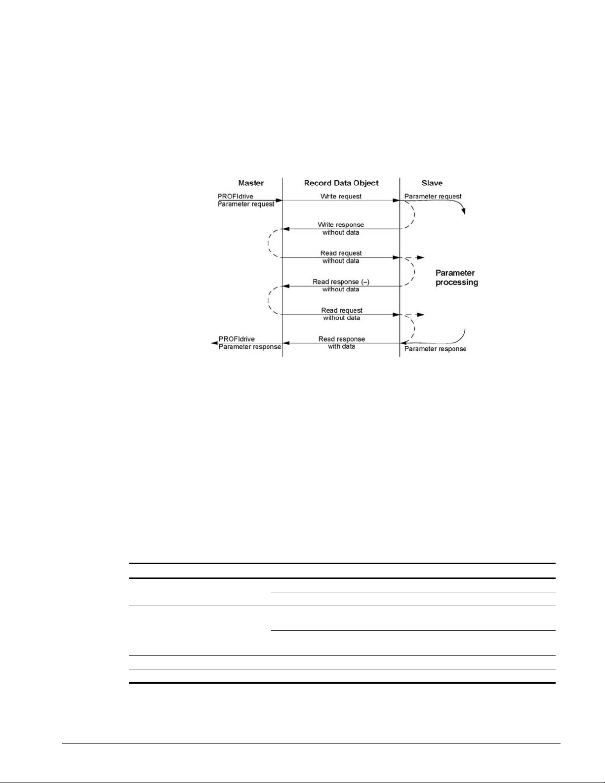
PROFIdrive Acyclic Parameter Access Mechanism
A PROFIdrive acyclic parameter access mechanism can be used to access PROFIdrive parameters
and drive parameters using an index of 0xB02E and the structure in Figure 12 for write and read
requests.
Requests and responses between the IO device and the IO controller or the IO supervisor are
transferred with the Record Data Objects.
Figure 12: PROFIdrive Acyclic Parameter Access Mechanism Structure
A write request is first sent containing the parameter request.
If the write request is valid, the SI-EP3 acknowledges it with request accepted. The master then
sends a read request. If the SI-EP3 is still busy performing the internal parameter request, it will
return a negative response with the error code “0xB5” (State conflict). In this case, the master
repeats the read request until the SI-EP3 has the PROFIdrive response data ready.
If the write request is invalid, a negative response is returned with an error code.
Base Mode Parameter Access - Local
The DO-ID field in the Record Data Object request header is not evaluated by the parameter
manager. Parameters can be read through any slot in the configuration.
Table 17: Response Error Codes
Byte Value and Meaning
ErrorCode
ErrorDecode 0x80 (PNIORW) ErrorCode1 decoded according to Table 18.
ErrorCode1 Error class and error code (Refer to Table 18).
ErrorCode2 Not described
0xDF (Error Write)
0xDE (Error Read)
ErrorCode2 is 0.
0x81 (PNIO) ErrorCode1 and ErrorCode2 decoded according to Table
18.
IMPULSE®•G+/VG+ Series 4 Profinet Installation Manual - August 2014
34
Page 35

Table 18: ErrorCode1 with PNIORW Decoding
Error class Meaning Error Code
0...9 (Reserved) -0 = Read error
1 = Write error
2 = Module failure
10 (0x0A) Application
11 (0x0B) Access
12 (0x0C) Resource
13...15 User-specific --
3...7 = Reserved
8 = Version conflict
9 = Feature not supported
10...15 = User-specific
0 = Invalid index
1 = Write length error
2 = Invalid slot
3 = Type conflict
4 = Invalid area
5 = State conflict
6 = Access denied
7 = Invalid range
8 = Invalid parameter
9 = Invalid type
10...15 = User-specific
0 = Read constraint conflict
1 = Write constraint conflict
2 = Resource busy
3 = Resource unavailable
4...7 = Reserved
8...15 = User-specific
The Read block is used in read requests and responses. The Write block is used in write requests
and responses. The request consists of unique identifiers for the conn ection, addressing infor mation
and length of the record data. The response also contains two additional fields for transferring
information.
Table 19: Structure of the Read and Write Blocks
Field(s) Description Range Type
Service Request or Response service.
Operation Read or Write operation.
Block length Length of the block. 0 … 0xFFFF UI16
Identifier
- time low
ARUUID
- time mid
- time high and version - clock node
Request (0x00)
Response (0x80)
Write (0x08)
Read (0x09)
--
IMPULSE®•G+/VG+ Series 4 Profinet Installation Manual - August 2014
UI8
UI8
UI32
UI16
UI16
Octet[2]
Octet[6]
35
Page 36

Field(s) Description Range Type
API Application Process Identifier
Slot
Sub-slot
Slot of the Module Access Point
(MAP/PAP)
Sub-slot of the Module Access
Point (MAP/PAP)
Device Access Point (0x0000)
PROFIdrive (0x3A00)
UI32
0x01 UI16
0x01 UI16
Padding 2 bytes
Index Index of the Record Data Object 0x0001 - 0x7FFF
UI16
0xB02E
Data length Length of the data block 0…0xFFFFFFFF UI32
Additional value 1
(response only)
Additional value 2
(response only)
Field for transferring additional
data
Field for transferring additional
data
-- UI16
-- UI16
Padding 24 bytes for request, 20 bytes for response.
Data block Used only with write request and read response.
Data block contains PROFIdrive specific request or response header.
Table 20: PROFIdrive Request Header
Field(s) Description Range Byte/Word
Request Reference
Request ID Request type for the issued block.
DO-ID To be set to 0x01. 0 … 255 Byte
No. of Parameters
Attribute Type of object being accessed. Value (0x10) Byte
No. of Elements
Parameter Index
(group)
Subindex
(parameter)
Format <1> Refer to Table 22 for details. -- Byte
Number of Va lues
<1>
<1> Only when Request ID is 0x02 (Change Parameter). The Format, Number of Values, and Value Fields are repeated for other
parameters.
Unique identification set by the master.
Changed for each new request.
1 … 255 Byte
Request Parameter
(0x01)
Change Parameter
Byte
(0x02)
Number of parameters that are present in
the request.
1 Byte
Number of array elements accessed or
length of string accessed. Set to 0 if non-
0, 1 … 234 Byte
array parameters are used.
Address of the PROFIdrive parameter that
is being accessed. Also “1” is allowed by SIEP3 to access drive parameters.
1 … 65535 Word
Drive parameter group when accessing
drive parameters.
Addresses the first array element of the
parameter.
Drive parameter number when accessing
0 … 65535 Word
drive parameters.
Number of values following. 1 Byte
IMPULSE®•G+/VG+ Series 4 Profinet Installation Manual - August 2014
36
Page 37

Field(s) Description Range Byte/Word
Values <1> The values of the request. In case of odd
number of bytes, a zero byte is appended to
Varies based on value See Format
Field
ensure the word structure of the telegram.
<1> Only when Request ID is 0x02 (Change Parameter). The Format, Number of Values, and Value Fields are repeated for other
parameters.
Table 21: PROFIdrive Response Header
Field(s) Description Range
Response
Reference
Response ID
DO-ID To be set to 1. 0 … 255
No. of
Parameters
Format <1> Refer to Table 22 for details. -Number of
Values <1>
Values <1> The values of the request.
<1> Only when Request ID is 0x01 (Request Parameter OK). The Format, Number of Values, and Value Fields are repeated for other
parameters.
Mirrored from the request. 1 … 255
Response from the slave. In the event that
requested services fail, a “not
acknowledged” (NAK) response will be
indicated.
Number of parameters that are present in
the response.
Request Param OK (0x01) Request Param
NAK (0x81) Change Param OK (0x02)
Change Param NAK (0x82)
1… 37
Number of values following. 0 … 234
Va ries based on value
When there is an odd number of bytes, a
zero byte is appended to ensure the word
structure of the telegram.
Table 22: Data Types for Format Field
Code Type
0x00 (Reserved)
0x01…0x36 Standard data types
0x37…0x3F (Reserved)
0x40 Zero
0x41 Byte
0x42 Word
0x43 Double word
0x44 Error
0x45 … 0xFF (Reserved)
Table 23: PROFIdrive Parameter Request Error Codes
Error Meaning Used at
0x00 Impermissible parameter number Access to unavailable parameter
0x01 Parameter value cannot be
changed
0x02 Low or high limit exceeded Change access with value outside the limits
0x03 Invalid subindex Access to unavailable subindex
0x04 No array Access with subindex to non-indexed parameter
Change access to a parameter value that cannot be
changed
IMPULSE®•G+/VG+ Series 4 Profinet Installation Manual - August 2014
37
Page 38

Error Meaning Used at
0x05 Incorrect data type Change access with value that does not match the
data type of the parameter
0x06 Setting not permitted (can only be
reset)
0x07 Description ele me nt cannot be
changed
Change access with value unequal to 0 when this is
not permitted
Change access to a description element that cannot
be changed
0x09 No description data available Access to unavailable description (parameter value
is available)
0x0B No operation priority Change access rights without rights to change
parameters
0x0F No text array available Access to text array that is not available (parameter
value is available)
0x11 Request cannot be executed
because of operating mode
Access is temporarily not possible for reasons that
are not specified in detail
0x14 Value impermissible Change access with a value that is within limits but is
not permissible for other long term reasons
(parameter with defined single values)
0x15 Response too long The length of the current response exceeds the
maximum transmittable length
0x16 Parameter address impermissible Illegal value or value that is not supported for the
attribute, number of elements, parameter number or
sub-index, or a combination
0x17 Illegal format Write request: Illegal format or format of parameter
data that is not supported
0x18 Number of values inconsistent Write request: Number of values of parameter data
does not match number of elements at the parameter
address
0x19 DO nonexistent Request to DO, which does not exist
0x65… 0xFF Manufacturer-specific --
0x65 Vendor-specific error Vendor-specific error
0x66 Request not supported Request not supported
0x67 Communication error Request cannot be completed because of
communication error
0x6F Time-out error Request aborted due to time-out
0x78 PZD map failure Parameter cannot be mapped to PZD (size
mismatch or non-existent)
0x79 PZD map failure Parameter cannot be mapped to PZD (size
mismatch or non-existent)
0x7A Multiple PZD map Parameter cannot be mapped to PZD (multiple PZD
write)
0x8C Set torque mode error Cannot change mode to TORQUE (frequency is
used)
0x90 Illegal Request ID The request ID of the response is illegal
IMPULSE®•G+/VG+ Series 4 Profinet Installation Manual - August 2014
38
Page 39
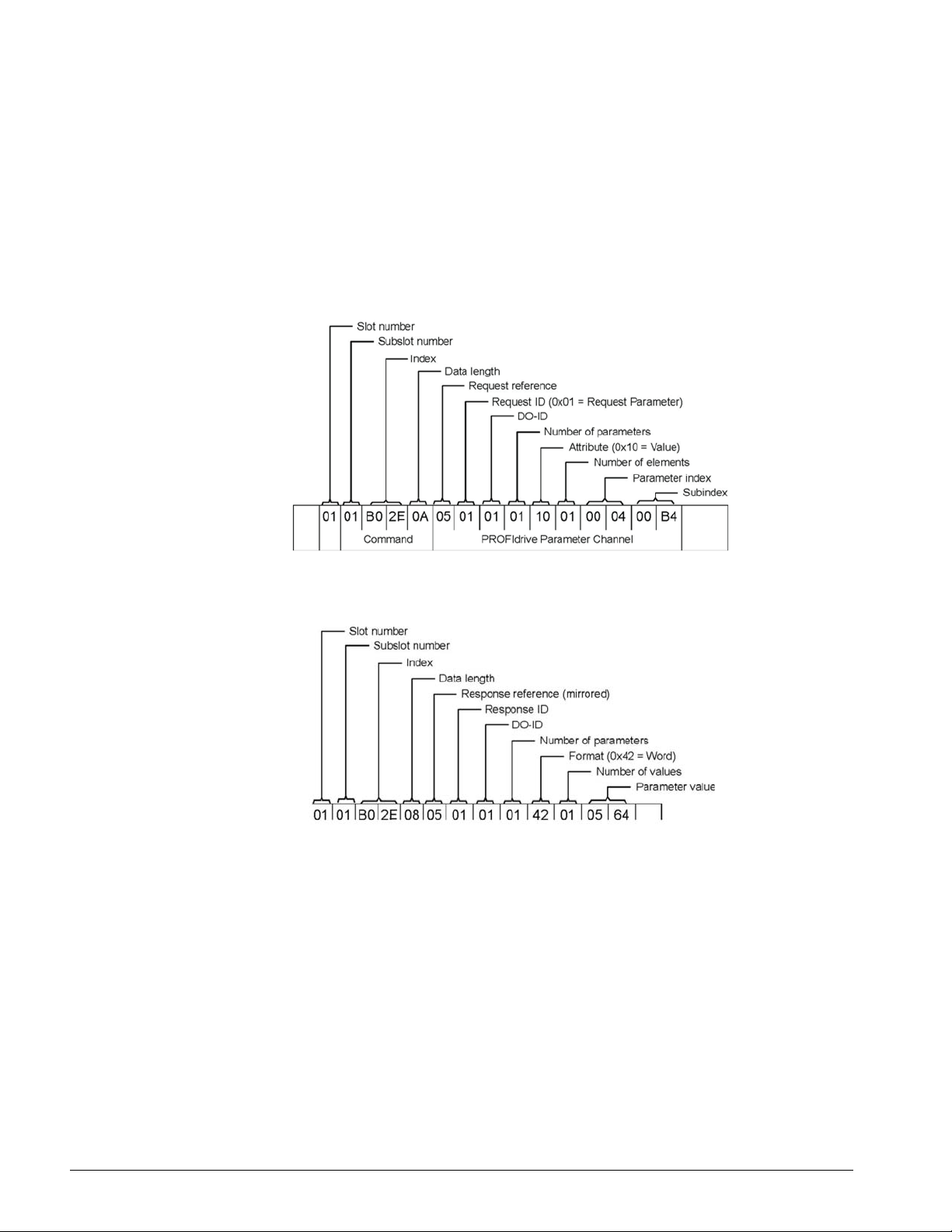
Parameter Data Transfer Examples
The following example shows how parameter dat a is tran sferred using the acyclic p arameter access
mechanism's READ and WRITE.
Example 1: Reading a drive parameter
To read a Magnetek Drive parameter, use the PNU of 1 and the actual address of the parameter in
the SubIndex.
Write Request (Read Parameter Value)
Positive Read Response to Read Request
PROFIdrive Parameter Channel
IMPULSE®•G+/VG+ Series 4 Profinet Installation Manual - August 2014
39
Page 40
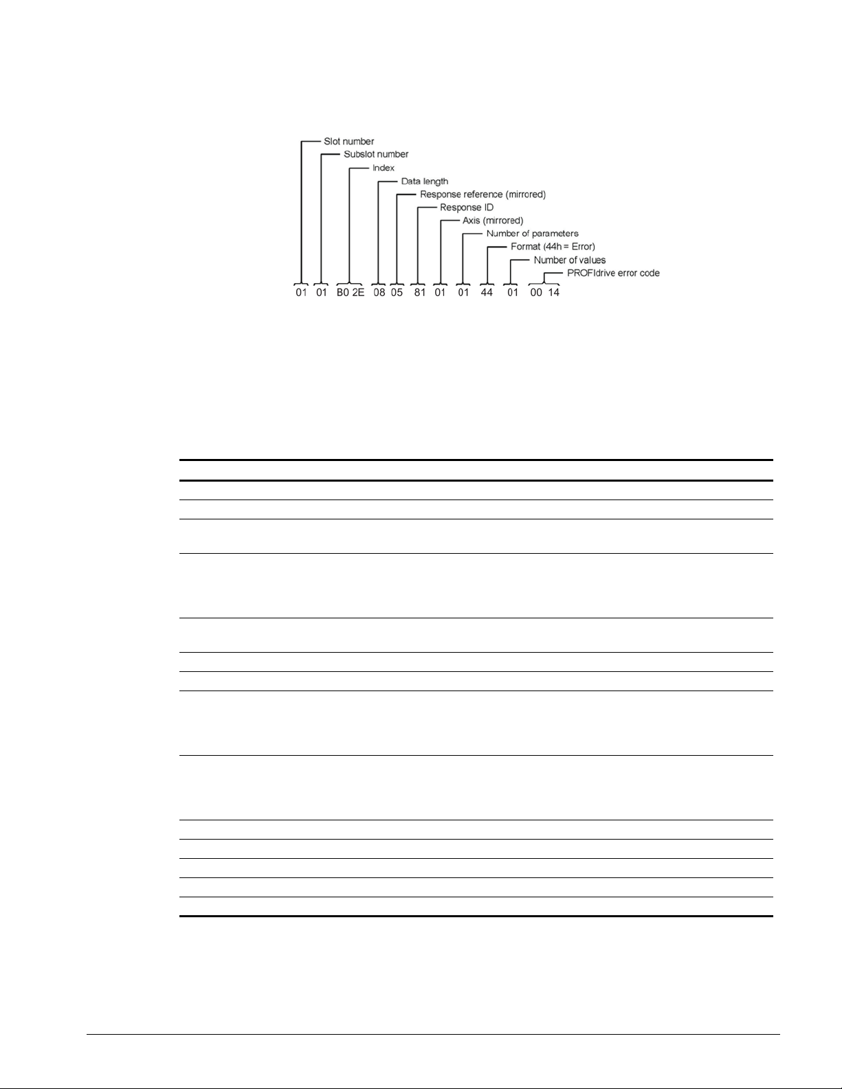
Negative Response to PROFIdrive Read Request
PROFIdrive Profile-Specific Parameters
PROFIdrive parameters contain dat a of the drive in st andard for m. Table 24 describes the supported
PROFIdrive parameters.
Table 24: Profile-Specific Parameters
Parameter R/W Data T ype Description
922 R Unsigned16 Telegram selection
944 R Unsigned16 Fault message counter
947 R Array [5] Unsigned16
964 R Array [6] Unsigned16
965 R Octet String2
967 R Unsigned16 Control word (CW)
968 R Unsigned16 Status word (SW)
972 R/W Unsigned16
977 R/W Unsigned16 Stores parameters to non-volatile memory V alue
61000 R VisibleString24 Name of station
61001 R Unsigned3 2 IP of station
61002 R Array [6] Unsigned8 MAC of station
61003 R Unsigned3 2 Default gateway of station
61004 R Unsigned32 Subnet mask of station
Fault number. (coded according to DRIVECOM
profile) Subindex Contents, see parameter 945.
Device identification Subindex Contents 0
Manufacturer 1 Device type 2 Version 3
Firmware date (year) 4 Firmware date (day/
month) 5 Number of Drive Objects (DO)
Profile number of this device. 0328h = Profile 3,
Version 40
Software reset Value Description 0 No action 1
Power-cycle PROFINET IO module.
The parameter must do a zero-to-one transition
and the motor must be stopped.
Description 0 No action 1 Stores parameters.
The parameter must do a zero-to-one transition
and the motor must be stopped.
IMPULSE®•G+/VG+ Series 4 Profinet Installation Manual - August 2014
40
Page 41

Fault Buffer Mechanism
The PROFIdrive profile has a mechanism that can store five fault situations to PROFIdrive
parameters. Fault and diagnostic data, like fault number and fault code, can be accessed
simultaneously with only one subindex. The mechanism consists of two PROFIdrive parameters:
• PNU944: Fault message counter
• PNU947: Fault numbers according to value in U02-01
Option High Priority Alarm Codes
These codes are transmitted as Manufacturer Specific Diagnost ic hig h pr ior ity ala rm s th at ca n be
seen in the PLC configuration software. These high prio rity codes are the same codes that appear in
the drive manual, except with an offset of 0x1000.
Table 25: PROFINET Option High Priority Alarm Codes
Drive Alarm
Code (hex) <1>
1000 None -1001 DC Bus Fuse Open (PUF) Output Transistor Failure. Replace the drive.
1002 DC Bus Undervolt (Uv1) Input power fluctuation too large.
1003 CTL PS Undervolt (Uv2) Cycle drive power and replace drive if fa ult continues
1004 MC Answerback (Uv3) Cycle drive power and replace drive if fault continues
1005 Short Circuit (SC) • Check drive wiring
1006 Ground Fault (GF) Check for motor and/or cable damage
1007 Over Current (oC) Check motor, motor load, and accel/decel rates
1008 DC Bus Overvolt (oV) • Check incoming voltage
1009 Heatsink Overtemp (oH) • Check ambient temperature
100A Heatsink max Temp (oH1) Check drive cooling fan
100B Motor Overload (oL1) • Check the load, accel/decel, and cycle times
100C Inv Overload (oL2) • Check the load, accel/decel, and cycle times
100D Overtorque Det 1 (OT1) • Check L06-02 and L06-03 settings
100E Overtorque Det 2 (OT2) • Check L06-05 and L06-06 settings
100F DynBrk Transistor (rr) Cycle drive power and replace drive if fault continues
1010 DynBrk Resistor (rH) Check load, operating speed, and deceleration time
1011 External Fault 3 (EF3) • MFDI set to external fault
1012 External Fault 4 (EF4)
1013 External Fault 5 (EF5)
1014 External Fault 6 (EF6)
1015 External Fault 7 (EF7)
1016 External Fault 8 (EF8)
1017 Heatsink Fan (FAn) Check drive cooling fan
<1> Drive error code is stored in MEMOBUS/Modbus address 0080 hex.
Description Corrective Action
• Cycle drive power and replace drive if fault continues
• Check deceleration time
• Check drive cooling fan
• Check motor rated current (E02-01)
• Check the drive rating
• Check system mechanics
• Check system mechanics
• Circuit at terminal is closed
IMPULSE®•G+/VG+ Series 4 Profinet Installation Manual - August 2014
41
Page 42

Drive Alarm
Code (hex) <1>
Description Corrective Action
1018 Overspeed Det (oS) • Check reference and reference gain
• Check F01-24 and F01-25 settings
1019 Speed Deviation (dEV) • Check load, accel/decel times, and system mechanics
• Check F01-27 and F01-28 settings
101A PG Open (PGO15) Check PG card connections
101B Input Phase Loss (PF) Excessive input voltage fluctuation
101C Output Phase Loss (LF) • Check for broken wire/loose terminals
• Check motor rating
101D None -101E Operator Disconnected
Reconnect the digital operation
(oPr)
101F EEPROM R/W Error (Err) Cycle drive power and replace drive if fault continues
1020 None -1021 Comm Error (bUS) • Check network cable connections
• Check 24 VDC power supply voltage
1022 Check option installation and connections
1023 Cycle drive power and replace option or drive if fault continues
1024
1025 Out of Control (CF) • Check motor parameters
• Auto-tune
1027 External Fault 0 (EF0) • Check PLC program
• Check MI switch setting
• Check option LEDs for fault indication
<1> Drive error code is stored in MEMOBUS/Modbus address 0080 hex.
IMPULSE®•G+/VG+ Series 4 Profinet Installation Manual - August 2014
42
Page 43

Option Low Priority Alarm Codes
These codes are transmitted as Manufacturer Specific Diagnostic low priority alarms that can be
seen in the PLC configuration software. These low priority codes are the same codes that appear in
the drive manual, except with an offset of 0x0400.
Table 26: PROFINET Option Low Priority Alarm Codes
Drive Alarm
Code (hex)
Description
<1>
0401 Undervoltage (Uv) 042E Maintenance Required Alert (MNT)
0402 Overvoltage (ov) 042F Klixon Circuit Alarm (KLX)
0403 Heatsink Overhead (oH) 0431 Option Watchdog Error (E5)
0404 Drive Overheat (oH2) 0432 Option Station Address Setting Error (AEr)
0405 Overtorque 1 (OT1) 0433 Option Comm. Cycle Setting Error (CyC)
0406 Overtorque 2 (OT2) 0434 High Current Alarm (HCA)
0407 Run Command Input Error (EF) 0435 Cooling Fan Maintenance Time (LT-1)
0408 Drive Baseblock (bb) 4036 Capacitor Maintenance Time (LT-2)
0409 External Fault 3, input terminal S3 (EF3) 0438 Option EEPROM Error (EEP)
040A External Fault 4, input terminal S4 (EF4) 0439 External Fault (input terminal S1) (EF1)
040B External Fault 5, input terminal S5 (EF5) 043A External Fault (input terminal S2) (EF2)
040C External Fault 6, input terminal S6 (EF6) 043B Safe Disable Input (HbbF)
040D External Fault 7, input terminal S7 (EF7) 043C Safe Disable Input (Hbb)
040E External Fault 8, input terminal S8 (EF8) 043D Mechanical Weakening Detection 1 (oL5)
040F Cooling Fan Error (FAn) 043E Mechanical Weakening Detection 2 (UL5)
0410 Overspeed (oS) 043F PLC Alarm (PA1)
0411 Excessive Speed Deviation (dEv) 0440 PLC Alarm (PA2)
0412 PG Disconnected (PGO15) 0441 Output Voltage Detection Fault (voF)
0414 MEMOBUS/Modbus Comm. Error (CE) 0442 IGBT Maintenance Time (90%) (TrPC)
0415 Option Communication Error (bUS) 0443 Soft Charge Bypass Relay Maintenance
0416 Serial Comm. Transmission Error (CALL) 0444 IGBT Maintenance Time (50%) (LT-4)
0417 Motor Overload (oL1) 0445 Braking Transistor Overload (boL)
0418 Drive Overload (oL2) 0448 Motor Overheat (NTC Input) (oH5)
041A Option Card External Fault (EF0) 0449 Load Check (LC)
041B Motor Switch Command Input during Run
(rUn)
041D Serial Comm. Transmission Error (CALL) 044B Upper Limit 2 Error (UL2)
041E Undertorque Detection 1 (UT1) 044C Lower Limit 2 Error (LL2)
041F Undertorque Detection 2 (UT2) 044E Upper Limit 1 Error (UL1)
0420 MEMOBUS/Modbus Test Mode Fault (SE) 044F Lower Limit 1 Error (LL1)
0422 Motor Overheat (oH3) 0450 Brake Answer Lost (BE0)
0427 PID Feedback Loss (FbL)
0428 PID Feedback Loss (FbH) 0452 Brake Answer 2 (BE5)
042A Drive Disabled (dnE) 0453 Brake Stop (BE6)
042B PG Disconnected (PGO1H) 0454 Brake Slipping (BE8)
042D Slack Cable Fault (SLC)
<1> Drive error code is stored in MEMOBUS/Modbus address 0080 hex.
Drive Alarm
Code (hex)
Description
<1>
Tim e (LT-3)
044A Upper Limit 3 Error (UL3)
0451 Brake Answer 1 (BE4)
IMPULSE®•G+/VG+ Series 4 Profinet Installation Manual - August 2014
43
Page 44

Identification and Maintenance Functions (I&M)
The purpose of the I&M functions is to provide support for the customer durin g commissioning,
parametrization, and repair of the module . SI-EP3 supports I&M function 0, which can be accessed
using the Record data object's read request.
Function Record Data Index
I&M0 0xAFF0
Structure of the I&M functions is described in the following tables.
Table 27: I&M0 Device Identification (Read-Only)
Content Size Description
Header 10 bytes --
Vendor ID 2 bytes PROFINET Vendor ID of Yaskawa, which is 0x19F
Order ID 20 bytes Order number of the SI-EP3 adapter kit (SI-EP3)
Serial number 16 bytes Serial number of the adapter
Hardware revision 2 bytes Hardware revision of the SI-EP3 adapter
Software revision 4 bytes Revision of the software
Revision counter 2 bytes Number of revision
Profile ID 2 bytes PROFIdrive (0x3A00)
Profile specific type 2 bytes No profile specific type (0x0000)
I&M version 2 bytes Version is 1.1 (0x0101)
Supported I&M functions 2 bytes I&M0 is supported (0x0001)
Diagnostic and Alarms
SI-EP3 has mechanisms for sending alarms and saving diagnostics data to fault buffer. Alarm will be
triggered if the host or drive has faults in communication or operation. There are thr ee types of faults :
Fault API/Slot/Sub-slot Channel Type Error
Drive Fault 0x3A00 / 1 / 1 A fault declared in drive
IMPULSE®•G+/VG+ Series 4 Profinet Installation Manual - August 2014
44
Page 45

Alarm Mechanism
When a fault or alarm situation occurs in the drive, the SI-EP3 adapter will send an alarm
notification, which the master station must acknowledge. Refer to Table 28 for details.
Table 28: Alarm Notification
Attribute Description
BlockHeader -AlarmType PROFINET specific alarm type
API 0x3A00 (PROFIdrive profile)
SlotNumber Slot number of the Drive Object (DO)
SubslotNumber
ModuleIdentNumber Module Ident number of the DO
SubmoduleIdentNumber 0xFFFF
AlarmSpecifier Diagnosis Type
UserStructureIdentifier 0x8000 (Channel Diagnosis Data)
ChannelNumber 0
ChannelProperties
ChannelErrorType Error code of dri ve fault or drive alarm
Sub-slot number of the sub-slot to which the
diagnosis object is related
0x0800 Diagnosis Appears
0x1000 Diagnosis Appears
IMPULSE®•G+/VG+ Series 4 Profinet Installation Manual - August 2014
45
Page 46
9. Web Interface
The web server interface to the drive option through port 80 allows management of diag nostic
information through a standard web browser. The web page is a Java applet that creates a tabbed
web page. The available tabs include:
•Main Tab
• Drive Status Tab
•Network Tab
• Doc links Tab
• Email Alerts Tab
• Parameter Access Tab <1>
• Configuration Tab <1>
•Custom Tab
<1> The Parameter Access and Configuration tabs are only acces sib le after enterin g a valid
password.
NOTE: PCs must have Java SE 6 Update 14 or later inst alled to view the web p ages. PCs without
Java will display web pages with limited features.
Access the web server interface by typing the IP address of the SI-EP3 option in a web browser
address.
Example: "http://192.168.1.20"
The SI-EP3 IP Address is available using drive digital operator to access Option Monitors U06-80 to
U06-83. Refer to “Option Monitors” on page 24.
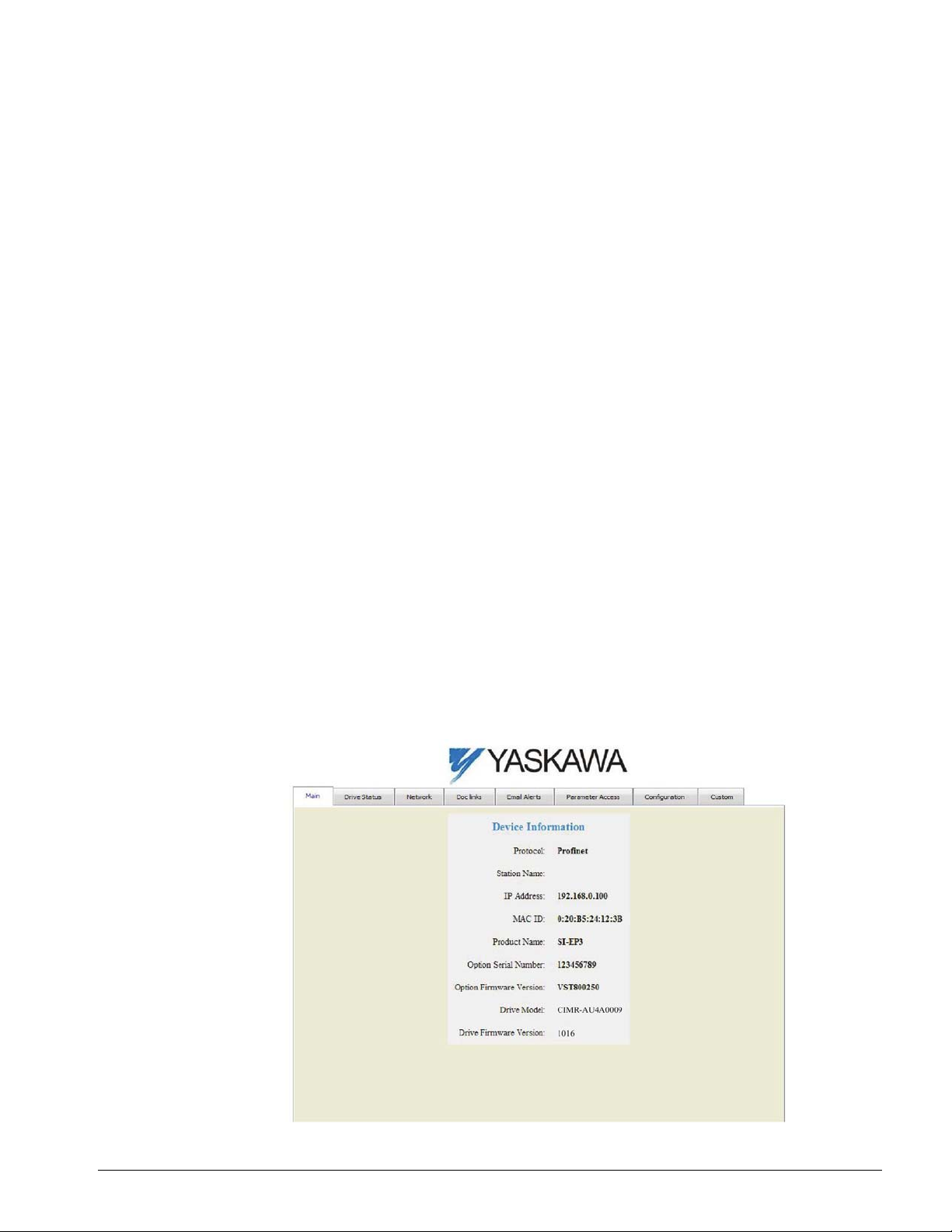
Main Tab
The Main tab shows basic option information such as IP address, MAC address, and firmware
version.
IMPULSE®•G+/VG+ Series 4 Profinet Installation Manual - August 2014
46
Figure 13: Main Tab View
Page 47
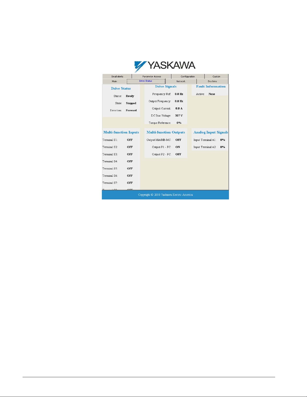
Drive Status Tab
The Drive Status tab shows basic I/O information and drive state information.
Figure 14: Drive Status Tab View
IMPULSE®•G+/VG+ Series 4 Profinet Installation Manual - August 2014
47
Page 48
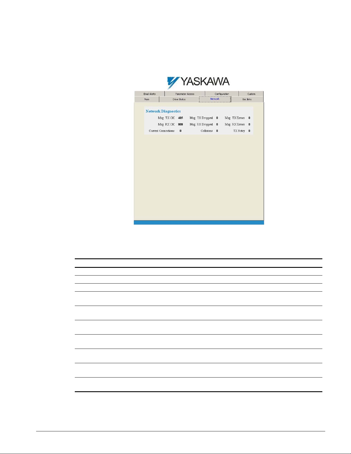
Network Tab
The Network tab shows the status of the option network traffic and the status of open I/O
connections.
Figure 15: Network Tab View
Table 29: Network Monitor Descriptions
Network Monitor Explanation
Msg Tx OK Cumulative number of messages transmit successfully from SI-EP3.
Msg Rx OK Cumulative number of messages received successfully to SI-EP3.
Current Connections Current number of open connections.
Control Connection Delta
Time
Msg Tx Dropped Cumulative number of messages dropped due to output network buffer being full
Msg Rx Dropped Cumulative number of messages dropped due to input network buffer being full
Collisions Cumulative number of collisions (half duplex only) reported by the MAC/PHY
Msg Tx Errors Cumulative number of transmit underruns and transmit stops reported by the
Msg Rx Errors Cumulative number of receive overruns, receive stops, and receive error frames
Tx Retry Cumula ti ve number of transmits in which the 1st attempt was delayed due to
NOTE: Cumulative counters are reset when the power supply is cycled.
The time between the last two writ es to the Control register, MEMOBUS/Modbus
address 0001H.
and unable to hold the new message.
and unable to hold the new message.
(Media Access Control/Physical Connection).
MAC/PHY.
reported by the MAC/PHY.
busy medium reported by the MAC/PHY.
IMPULSE®•G+/VG+ Series 4 Profinet Installation Manual - August 2014
48
Page 49
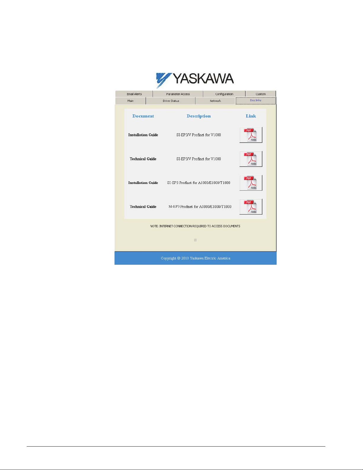
Doc Links Tab
The Doc links tab contains links to the option documentation on the Yaskawa website.
Figure 16: Doc Links Tab View
IMPULSE®•G+/VG+ Series 4 Profinet Installation Manual - August 2014
49
Page 50
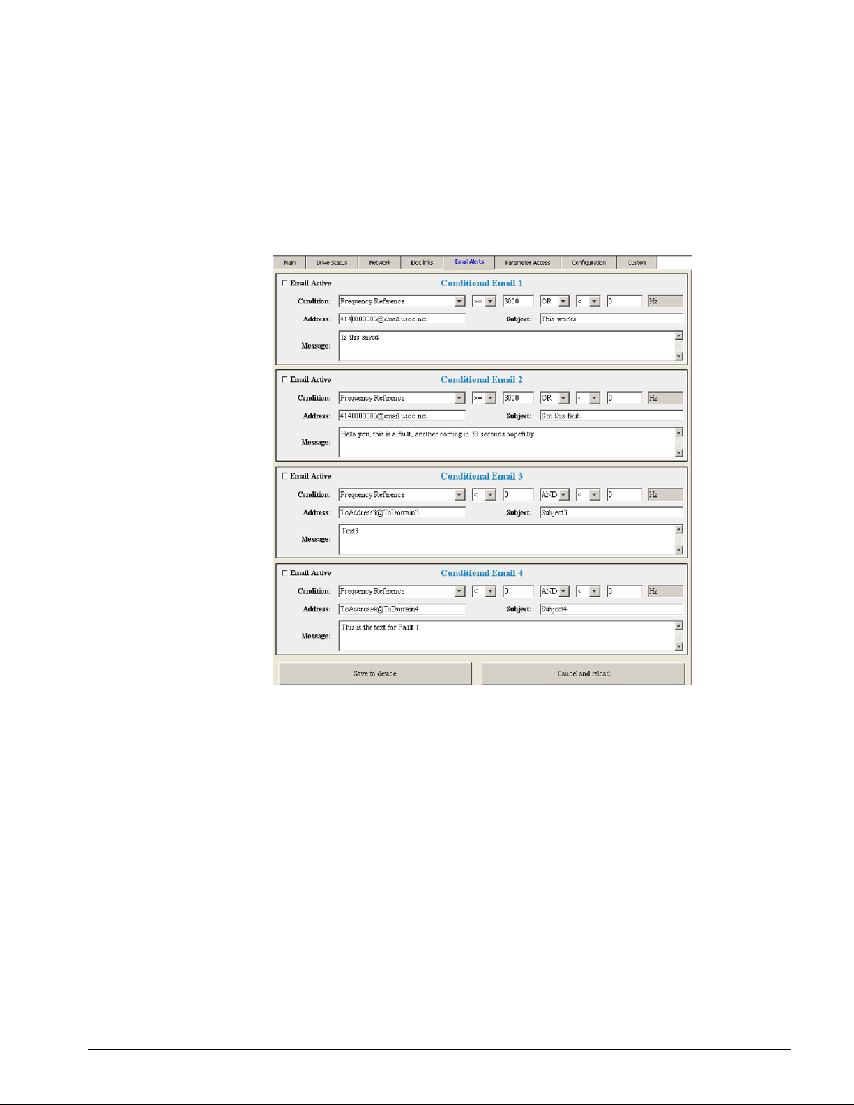
Email Alerts Tab
The Email Alerts tab allows the user to configure four Email Fault/Alarm conditions. When the
condition is true, one email will be sent to the provided email address. Another email will not be sent
until the condition becomes false and then true again. A 30-second timer pr events emails from being
sent when conditions reoccur immediately after being removed. The timer helps limit the amount of
emails sent regarding the same intermittent condition and helps to reduce network traffic by reducing
emails about reoccurring errors.
Figure 17: Email Alerts Tab View
Procedure: Conditional Email Set-up
1. Define the condition that will trigger the email by selecting a monitor parameter, a comparator,
and a value. Set up comparator values for the range of values to check in the chosen condition.
If choosing only one condition and no OR or AND are needed, set the “OR/AND” drop-down
selection to “NotUsed”.
2. Enter the email address where the alert will be sent.
3. Enter the message that will appear in the email contents.
4. Enter the email subject.
5. Click the “Email Active” check box to enable the alert.
Clicking “Save to device” will save the entered information into the option memory.
Clicking “Cancel and reload” will cancel any pending edits and display the most recently saved
settings from the option board.
IMPULSE®•G+/VG+ Series 4 Profinet Installation Manual - August 2014
50
Page 51
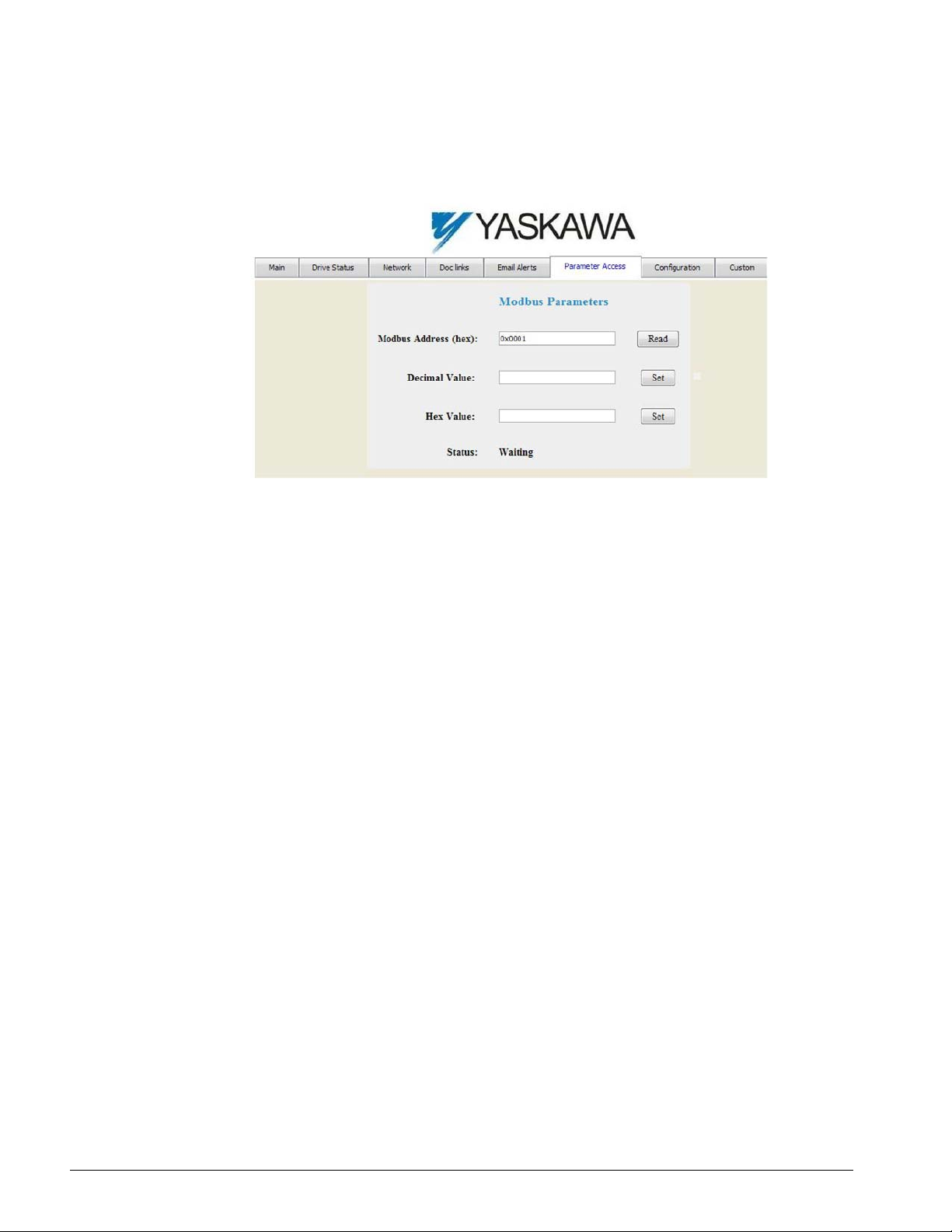
Parameter Access Tab
The Parameter Access tab allows the user to re ad and write p arameters from the drive . Write access
is restricted until a valid password is entered.
Figure 18: Parameter Access Tab View
The MEMOBUS/Modbus address for the drive parameter being accessed must be entered in
hexadecimal. The number must begin with “0x” to signify hexadecimal.
Clicking “Read” will load and display the current value of the given MEMOBUS/Modbus Address.
Clicking “Set” will save the given value to the given MEMOBUS/Modbus address.
After a “Read” or “Set” command is given, Status will display “Waiting” while the action is being
carried out, then “Complete” is displayed when finished.
IMPULSE®•G+/VG+ Series 4 Profinet Installation Manual - August 2014
51
Page 52
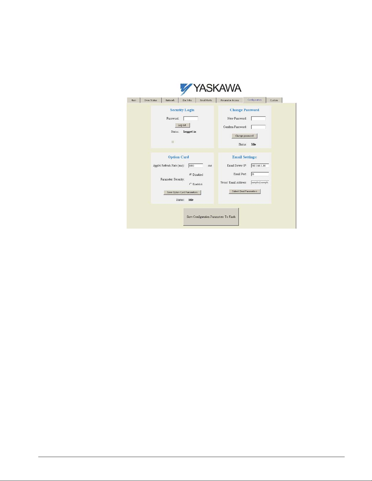
Configuration Tab
The Configuration tab sets web page behavior parameters. Access is restricted unless a valid
password is entered.
Figure 19: Configuration Tab View
Security Login
Enter a valid password and click “Log in”. The button text will change to “Log out” and the status will
change to “Logged in”.
NOTE: The default security password is “yaskawa”.
This password can be changed in the “Change Password” section of the tab. Entering a valid
password allows access to the settings in the Configuration t ab, Email Alert s t ab, and th e Parameter
Access tab.
Change Password
To change the password, enter the new password in the “New Password:” and “Confirm Password:”
text boxes, and then click “Change password”. The Status display will change to “Idle,” then
“Changing Password,” and then “Password Changed”. If the passwords in the two text boxes do not
match, the Status will display “Passwords don’t match”.
Option Card
The values displayed in the various tabs are refreshed at the rate defined in the “Applet Refresh
Rate (ms)” text box. Enter values in the range of 1000 ms to 65535 ms (65.535 seconds).
Parameter Security can be enabled or disabled by clicking one of the radio buttons. When “Disabled”
is selected, no password is necessary and all functions in the web pages will be available. When
“Enabled” is selected, a valid password must be entered to edit email settings and to write
parameters.
IMPULSE®•G+/VG+ Series 4 Profinet Installation Manual - August 2014
52
Page 53

Email Settings
The “Email Server IP” text box must contain the IP address of the email server. The subnet address
is configured in drive parameters F07-05 through F07-08. The configured email alerts will use the
server at this address when sending emails.
Enter the email server port in the “Email Port” text box.
The value in the “’From’ Email Address” text box identifies the origin of the email alerts to the
recipient.
Click “Submit Email Parameters” to save the email settings to the option.
Click “Save Configuration Parameters to Flash” to save the entered values from this tab into non-
volatile memory . These values will then be remembered after cycling power.
General Settings
Click “Save Options Card Parameters” to save the Applet Refresh Rate and the Parameter Security
settings to the option.
IMPULSE®•G+/VG+ Series 4 Profinet Installation Manual - August 2014
53
Page 54
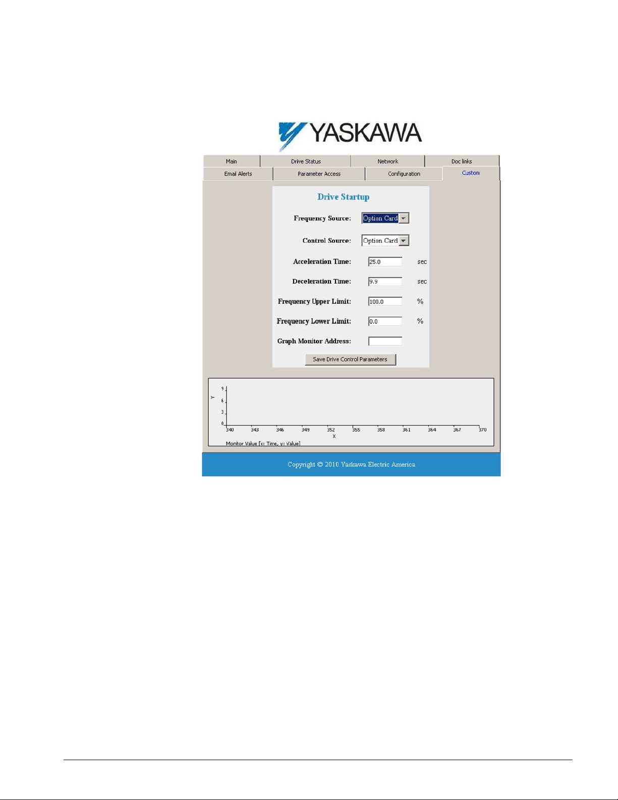
Custom Tab
The Custom tab displays a selection of quick setting parameters.
Figure 20: Custom Tab View
IMPULSE®•G+/VG+ Series 4 Profinet Installation Manual - August 2014
54
Page 55
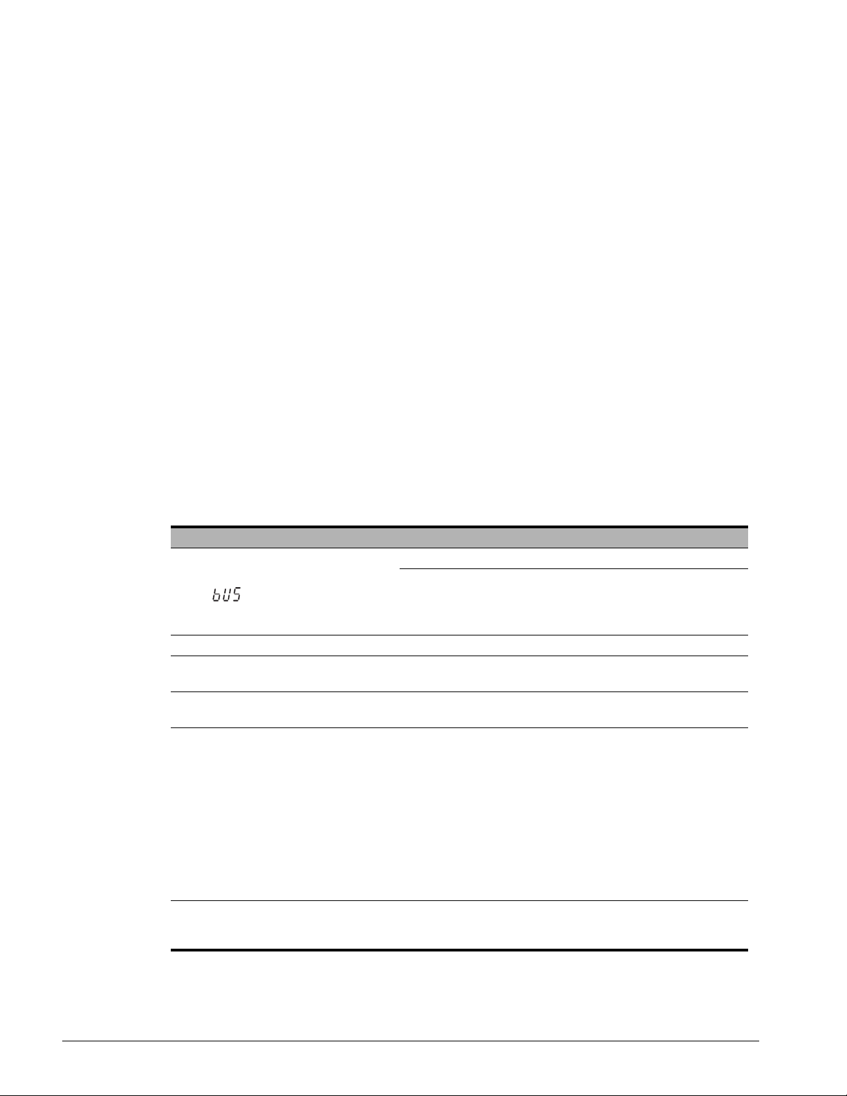
10. Troubleshooting
Drive-Side Error Codes
Drive-side error codes appear on the drive digital operator. Causes of the errors and corrective
actions are listed in Table 30. For additional error codes that may appear on the drive digital
operator, refer to the drive’s Instruction Manual.
Faults
Both bUS (SI-EP3 option communication error) and EF0 (External fault input from the SI-EP3 option)
can appear as an alarm or as a fault. When a fault occurs, the digital operator ALM LED remains lit.
When an alarm occurs, the ALM LED flashes.
If communication stops while the drive is running, use the following questions as a guide to help
remedy the fault:
• Is the option properly installed?
• Is the communication line properly connected to the option? Is it loose?
• Is the controller program working? Has the controller/PLC CPU stopped?
• Did a momentary power loss interrupt communications?
Table 30: Fault Displays, Causes, and Possible Solutions
LED Operator Display Fault Name
bUS
Cause Possible Solution
Master controller (PLC) has stopped
communicating
Communication cable is not connected
properly
A data error occurred due to noise
Option is damaged
Option Communication Error.
The connection was lost after establishing initial
communication.
Only detected when the run command frequency reference is
assigned to the option (B03-01 = 3 or B03-02 = 3).
Check that power is supplied to the PLC
Check that PLC is not in program mode
Check for faulty wiring
Correct any wiring problems
Check the various options available to minimize the effects of
noise
Counteract noise in the control circuit, main circuit, and
ground wiring
If a magnetic contactor is identified as a source of noise,
install a surge absorber to the contactor coil
Make sure the cable used meets the PROFINET
requirements
Make sure the option ground wire is connected between
option FE terminal and the drive ground terminal connected to
earth ground
If there are no problems with the wiring and the error
continues to occur, replace the option
IMPULSE®•G+/VG+ Series 4 Profinet Installation Manual - August 2014
55
Page 56
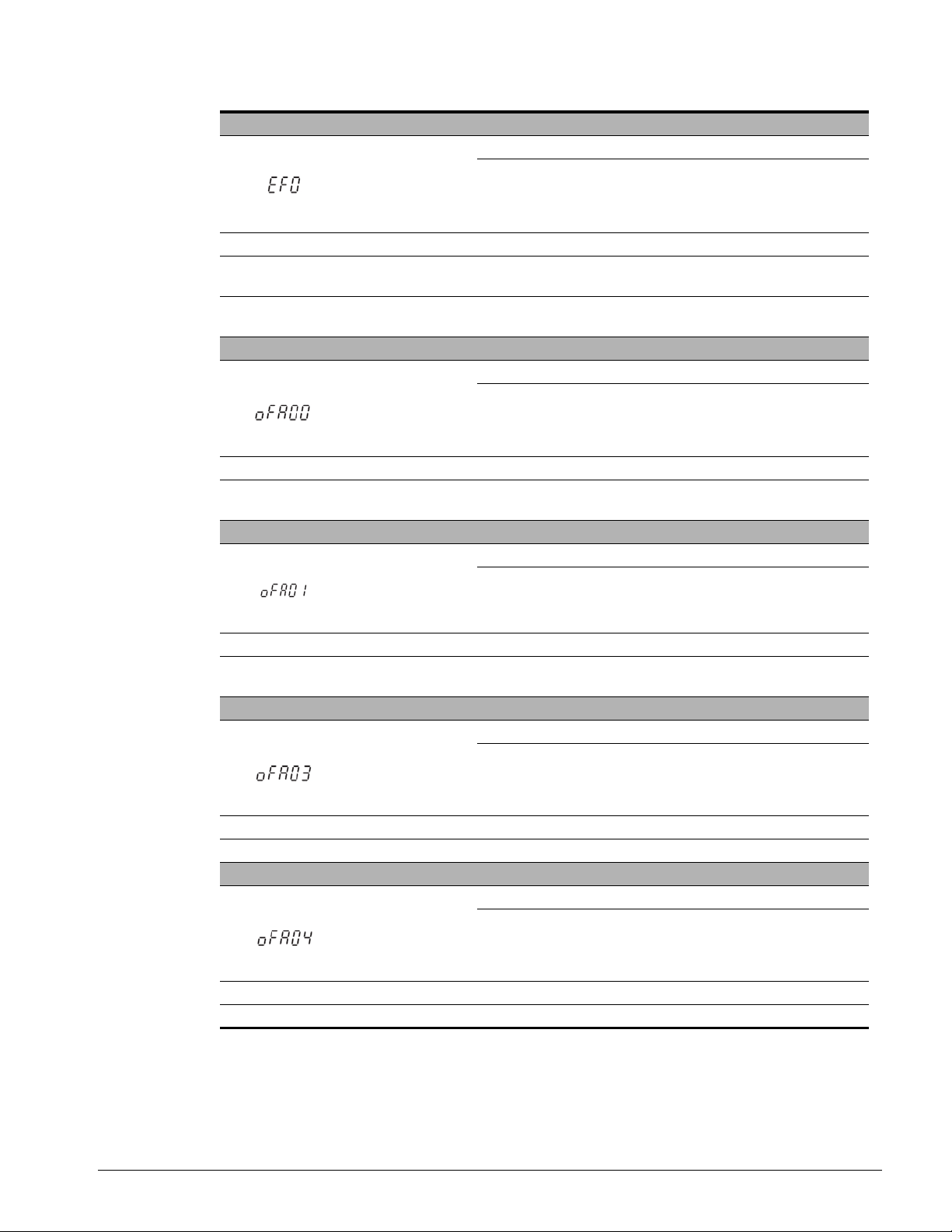
LED Operator Display Fault Name
EF0
Cause Possible Solution
An external fault is being sent from the
upper controller (PLC)
Problem with the PLC program
LED Operator Display Fault Name
oFA00
Cause Possible Solution
Non-compatible option connected to the
drive
LED Operator Display Fault Name
oFA01
External Fault Input from the option.
The alarm function for an external device has been triggered.
Remove the cause of the external fault
Reset the external fault input from the PLC device
Check the program used by the PLC and make the
appropriate corrections.
Option fault
Option is not properly connected.
Connect an option that is compatible with the drive.
Option Fault
Option is not properly connected.
Cause Possible Solution
Problem with the connectors between
the drive and option
Turn the power off and check the connectors between the
drive and option.
LED Operator Display Fault Name
Option self-diagnostics error.
oFA03
Cause Possible Solution
Option hardware fault Replace the option.
LED Operator Display Fault Name
Option flash write mode.
oFA04
Cause Possible Solution
Option hardware fault Replace the option.
Option Fault
Option Fault
IMPULSE®•G+/VG+ Series 4 Profinet Installation Manual - August 2014
56
Page 57
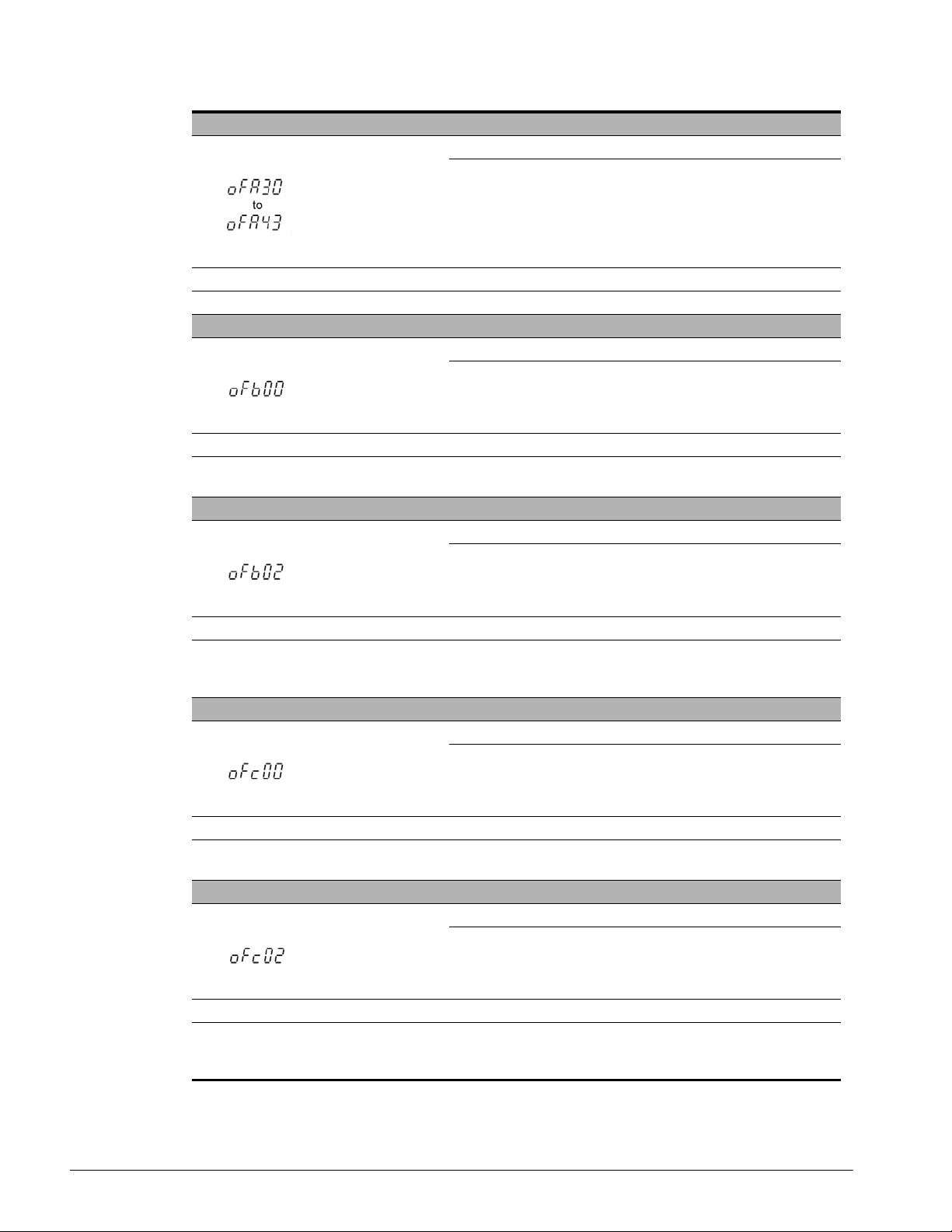
LED Operator Display Fault Name
oFA30 to oFA43
Cause Possible Solution
Option hardware fault Replace the option.
LED Operator Display Fault Name
oFb00
Cause Possible Solution
Non-compatible option connected to the
drive.
LED Operator Display Fault Name
oFb02
Option Fault (Port A)
Communication ID Error.
Option fault (CN5-B)
Non-compatible option is connected.
Connect the correct option to CN5-A.
Option fault (CN5-B).
Two of the same options are connected at the same time.
Cause Possible Solution
Options AI-A3 or D1-A3 were
connected to the CN5-B port while an
option was connected to CN5-A.
LED Operator Display Fault Name
oFc00
Cause Possible Solution
Non-compatible option connected to the
drive.
LED Operator Display Fault Name
oFc02
Cause Possible Solution
Options AI-A3 or D1-A3 were
connected to the CN5-C port while an
option was connected to CN5-A.
Only one type of AI-A3 or DI-A3 option can be connected to
the drive.
The SI-EP3 option can only be connected to CN5-A.
Option Fault (CN5-C)
Non-compatible option is connected.
Connect the correct option to CN5-A.
Option Fault (CN5-C)
Two of the same options are connected simultaneously.
Only one of these options, AI-A3, DI-A3, or SI-XX, can be
connected to the drive at the same time. The SI-N3 must be
connected to CN5-A.
IMPULSE®•G+/VG+ Series 4 Profinet Installation Manual - August 2014
57
Page 58
Minor Faults and Alarms
LED Operator Display Minor Fault Name
CALL
Cause Possible Solution
Communication wiring is faulty, there is
a short circuit, or improper connection
Programming error on the master side
Communication circuitry is damaged
Serial Communication Transmission Error
Communication has not yet been established.
Check for wiring errors:
Correct the wiring
Remove any ground shorts and reconnect loose
wires
Check communications at start-up and correct
programming errors.
Perform a self-diagnostics check
Replace the drive if the fault continues to occur.
Minor
Fault (H02-
XX = 10)
YES
IMPULSE®•G+/VG+ Series 4 Profinet Installation Manual - August 2014
58
Page 59

Option Fault Monitors U06-98 and U06-99
The option can declare error/warning conditions via drive monitor parameters on the drive digital
operator as shown in Table 31.
Table 31: Option Fault Monitor Descriptions
Fault Condition Fault Declared
No Fault n/a 0 No faults.
Force Fault EF0 3 Network sent a message to force this node to the
Network Link
Down
Network Failure BUS ERROR 1301 Connection with PLC Timeout.
Default MAC
Address
No IP Address None 1304 No IP Address has been programmed into the
No Station
Name
Config Error None 1306 Configuration error on power-up.
Init. Failure None 1307 Initialize error on power-up.
Permanent
Communication
Loss
BUS ERROR 1300 No network link to option board.
Non 1303 Factory default MAC Address programmed into the
None 1305 No Station Name has been programmed into the
BUS ERROR 1308 Fatal error in MAC/PHY hardware, requires power
Status Value
(U06-98/U06-99)
Description
fault state.
option. Return for reprogramming.
option.
option.
cycle to recover.
Two drive monitor parameters, U06-98 and U06-99, assist in network troubleshooting:
• U06-98 displays the first declared fault since the last power cycle. U6-98 is only cleared upon
drive power-up.
• U06-99 displays the present option SI-EP3 status. U06-99 is cleared upon a network-issued
fault reset and upon power-up.
If another fault occurs while the original fault is still active, parameter U06-98 retains the original fault
value and U06-99 stores the new fault status value.
Option Compatibility
A limited number of options may be simultaneously connected to the drive depen ding on the type of
option. Refer to Table 32 for more information. More details can be found in the manual(s) for the
option(s) in question.
Table 32: Option Installation Compatibility
Option Connector Number of Possible Op tions
SI-C3, SI-N3, SI-P3, SI-S3,
SI-EP3, SI-EN3, SI-EM3 <1>
PG-B3, PG-X3 CN5-B, C 2 <2>
DO-A3, AO-A3, AI-A3, DI-A3 CN5-A, B, C 1
<1> When installed in CN5-A, the AI-A3 and DI-A3 options can be used to set the frequency reference or re place the
drive analog inputs with higher resolution. When installed in CN5-B or CN5-C, these options can only be used for
monitoring; their input levels will be displayed in U01-17 or U01-21 to U01-23.
<2> Use the CN5-C connector when connecting only one option to the drive; use both CN5-B and CN5-C when
connecting two options.
CN5-A 1
IMPULSE®•G+/VG+ Series 4 Profinet Installation Manual - August 2014
59
Page 60

11. Specifications
Items Specifications
Model SI-EP3
Option Conformance Pa ssed PROFINET Conformance Class A
Connector Type Dual RJ45 8-pin Shielded Twisted Pair CAT5e cable
Physical Layer Type
IP Address Setting Programmable from drive keypad or network
Communication
Speed
Number of
Connections
Duplex Mode Half-forced, Auto-Negotiate, Full-forced
Address Startup
Mode
Ambient
Temperature
Humidity Up to 95% RH (no condensation)
Storage
Temperature
Area of Use Indoor (free of corrosive gas, airborne particles, etc.)
Altitude Up to 1000 m
PROFINET
Functions
IEC Overvoltage
Category
Table 33: Option Specifications
Isolated Physical Layer
TCP Protocol Transformer Isolated
Programmable from drive keypad or network:
10/100 Mbps, auto-negotiate.
1 PLC connection, 1 supervisor connection, 2 web page connections
Static, DHCP
°C to +50°C
-10
°C to +60°C (allowed for short-term transport of the product)
-20
PROFINET IO with PROFIdrive profile
Configurable I/O in cyclic messages
Drive diagnostic alarms
I & M0
Intended for use in “Overvoltage Category II” as specified in IEC
60664-1
IMPULSE®•G+/VG+ Series 4 Profinet Installation Manual - August 2014
60
 Loading...