

Page 1
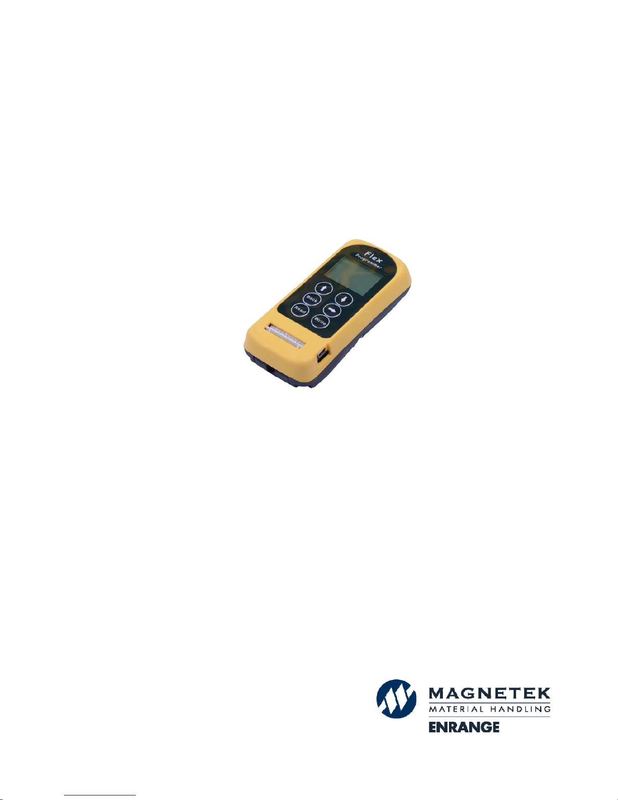
IR Programmer
Instruction Manual
V2.1 (February 2018)
Page 2

Page 1
Table of Content s
Page
1. External Illustrations 2
2. Power On/Off the Unit 3
3. Model Selection 3
4. Flex EX Models 4
5. Flex EX2 Models 9
6. Flex 2JX Models 17
7. Flex Mini Models 41
8. Flex BASE Models 44
9. Flex EP-H Models 50
10. TAC Programming 76
11. Firmware Update 78
12. Pushbutton Function Table
A. Flex EX Models 87
B. Flex EX2 Models 101
C. Flex BASE Models 115
Page 3
Page 2
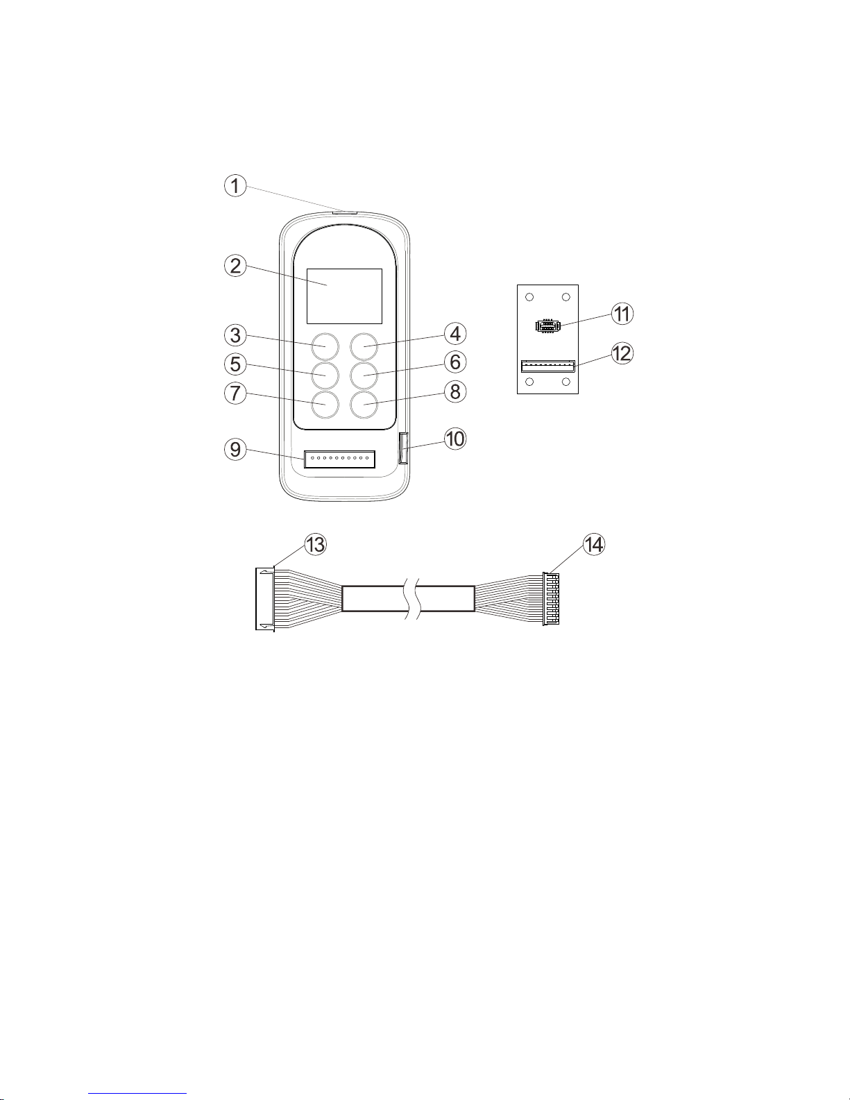
1. External Illustrations
1. Infrared sensors 8. “WRITE” button
2. LCD screen 9. Programming port
3. “
↑” button 10. Mini USB Port (for firmware update)
4. “
↓” button 11. I-Chip port
5. “BACK” button 12. I-Chip programming board connector
6. “
→” button 13. Connector to programming port
7. “READ” button 14. Connector to I-Chip programming board
(TX & RX) → Programming for both transmitter and receiver
(TX) → Programming for transmitter only
(RX) → Programming for receiver only
Page 4
Page 3
>FLEX-EX
FLEX-2JX
FLEX-Mini
FLEX-ECO
>FLEX-EX
FLEX-2JX
FLEX-Mini
FLEX-ECO
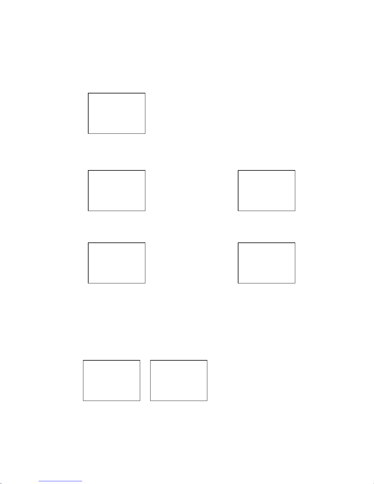
2. Power On/Off the Unit
1) Nothing is shown on the LCD screen when power is off.
Power off
2) Press the “→” button to power on the unit.
Power off Power on
Press “→” button
3) Press the “Back” button at type model main screen to power off the unit.
Power on Power off
Press “Back” button
4) The unit will power off after 10 minutes of inactivity.
5) Change battery immediately when the LCD backlights flash repeatedly.
3. Model Selection
At type model main screen use the “↑” and “↓” buttons to scroll between
models. Press “→” button to enter the selected type model (cursor shown
next to the type model). To deselect the type model after entering press the
“Back” button until the type model main screen is shown again. Press the
“Back” button again to turn off the programmer.
>FLEX-EX
FLEX-2JX
FLEX-Mini
FLEX-ECO
>FLEX-EPH
Page 5
Page 4
>PROGRAM
I-CHIP
ERASE
4. Flex EX Models
4.1 Program I-Chip
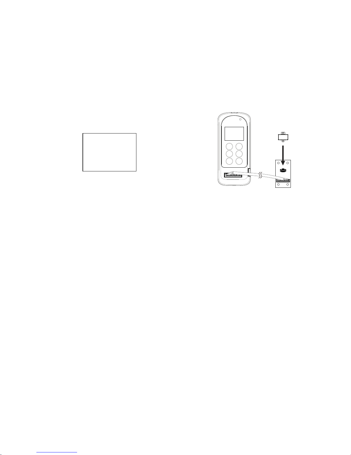
When entering the Flex EX model the first selection shown on the screen is
“Program I-Chip”. Use the “↑” and “↓” buttons to scroll through various Flex
EX settings or press “→” button to enter “Program I-Chip”. Make sure the IChip is connected to the programmer.
1) Press “→” button to erase I-Chip information, press “→” button again to
execute. “ERASE OK” is shown on the screen when completed.
2) Press “READ” button to store the I-Chip information into the programmer.
If the screen shows “READ OK” the transfer is completed.
3) Press “WRITE” button to transfer the stored I-Chip information into a new
I-Chip. If the screen shows “WRITE OK” the transfer is completed.
4) Exit Program I-Chip by pressing the “BACK” button until the cursor is
shown next to “PROGRAM”.
5) Press “↑” and “↓” button to scroll through other Flex EX settings.
4.2 Program Serial Number (TX & RX)
1) Make sure the I-Chip is connected to the programmer.
2) Press “→” button to enter Serial Number setting.
3) Press “↑” and “↓” button to change serial number as a whole or…
4) Press “→” button to go to the 1st digit on the far left of the serial number.
5) Press “↑” and “↓” button to change numeric value.
6) Press “→” button to go to the next digit to the right and repeat step 5.
7) Press “BACK” button to go back to step 3 or 4.
8) Exit Program Serial Number by pressing the “BACK” button until the cursor
is shown next to “S/N:”.
9) Press “↑” and “↓” button to scroll through other Flex EX settings.
When finished, take out the I-Chip and insert it onto the I-Chip programming port located on
the decoder module to transfer the new serial number from the I-Chip to the receiver. Make
sure JP6 jumper is inserted when transferring I-Chip information into the receiver.
Page 6

Page 5
4.3 Program System Type (TX & RX)
1) Make sure the I-Chip is connected to the programmer.
2) Press “→” button to enter System Type setting.
3) Press “↑” and “↓” button to change system type as a whole or…
4) Press “→” button to go to the digit on the left.
5) Press “↑” and “↓” button to change numeric value.
6) Press “→” button to go to the next digit to the right and repeat step 5.
7) Press “BACK” button to go back to step 3 or 4.
8) Exit Program System Type by pressing the “BACK” button until the cursor
is shown next to “TYPE:”.
9) Press “↑” and “↓” button to scroll through other Flex EX settings.
When finished, take out the I-Chip and insert it onto the I-Chip programming port located on
the decoder module to transfer the new system type from the I-Chip to the receiver. Make
sure JP6 jumper is inserted when transferring I-Chip information into the receiver.
4.4 Program System Frequency Range (TX)
1) Make sure the I-Chip is connected to the programmer.
2) Press “→” button to enter System Frequency Range setting.
3) Press “↑” and “↓” button to change frequency range.
4) Exit Program System Frequency Range by pressing the “BACK” button
until the cursor is shown next to “FREQ:”.
5) Press “↑” and “↓” button to scroll through other Flex EX settings.
When changing the frequency range table in I-Chip make sure the transmitting and receiving
RF boards are also changed accordingly.
4.5 Program System Channel (TX)
1) Make sure the I-Chip is connected to the programmer.
2) Press “→” button to enter System Channel setting.
3) Press “↑” and “↓” button to change system channel as a whole or…
4) Press “→” button to go to the digit on the left.
5) Press “↑” and “↓” button to change numeric value.
6) Press “→” button to go to the next digit to the right and repeat step 5
7) Press “BACK” button to go back to step 3 or 4.
8) Exit Program System Channel by pressing the “BACK” button until the
cursor is shown next to “CHANNEL”.
9) Press “↑” and “↓” button to scroll through other Flex EX settings.
4.6 Program RF Power (TX)
1) Make sure the I-Chip is connected to the programmer.
2) Press “→” button to enter RF Power setting.
3) Press “↑” and “↓” button to change RF power (0.01 ~ 10mW).
4) Exit Program RF Power by pressing the “BACK” button until the cursor is
shown next to “RFpower”.
5) Press “↑” and “↓” button to scroll through other Flex EX settings.
Page 7
Page 6
4.7 Program Transmitter Inactivity Timer (TX)
1) Make sure the I-Chip is connected to the programmer.
2) Press “→” button to enter Transmitting Timer setting.
3) Press “↑” and “↓” button to select __M, __S or ON (constant ON).
4) When Minutes or Seconds is selected, press “→” button to go to the first
digit on the left and press “↑” and “↓” button to select numeric value.
5) Press “→” button to go the next digit to the right and press “↑” and “↓”
button to select numeric value.
6) Press “→” button again to go to the next column to select “M” for minutes
and “S” for seconds. Press “↑” and “↓” button to select.
7) Press “BACK” button to go back to step 3 or 4.
8) Exit Program Transmitter Timer by pressing the “BACK” button until the
cursor is shown next to “TX TIMER”.
9) Press “↑” and “↓” button to scroll through other Flex EX settings.
4.8 Program Password (TX)
1) Make sure the I-Chip is connected to the programmer.
2) Press “→” button to enter Password setting.
3) Press “→” button to go to the 1st digit on the far left.
4) Press “↑” and “↓” button to change numeric value.
5) Press “→” button to go to the next digit to the right and repeat step 4.
6) Press “BACK” button to go back to step 3.
7) Exit Program Password by pressing the “BACK” button until the cursor is
shown next to “PASS WORD”.
8) Press “↑” and “↓” button to scroll through other Flex EX settings.
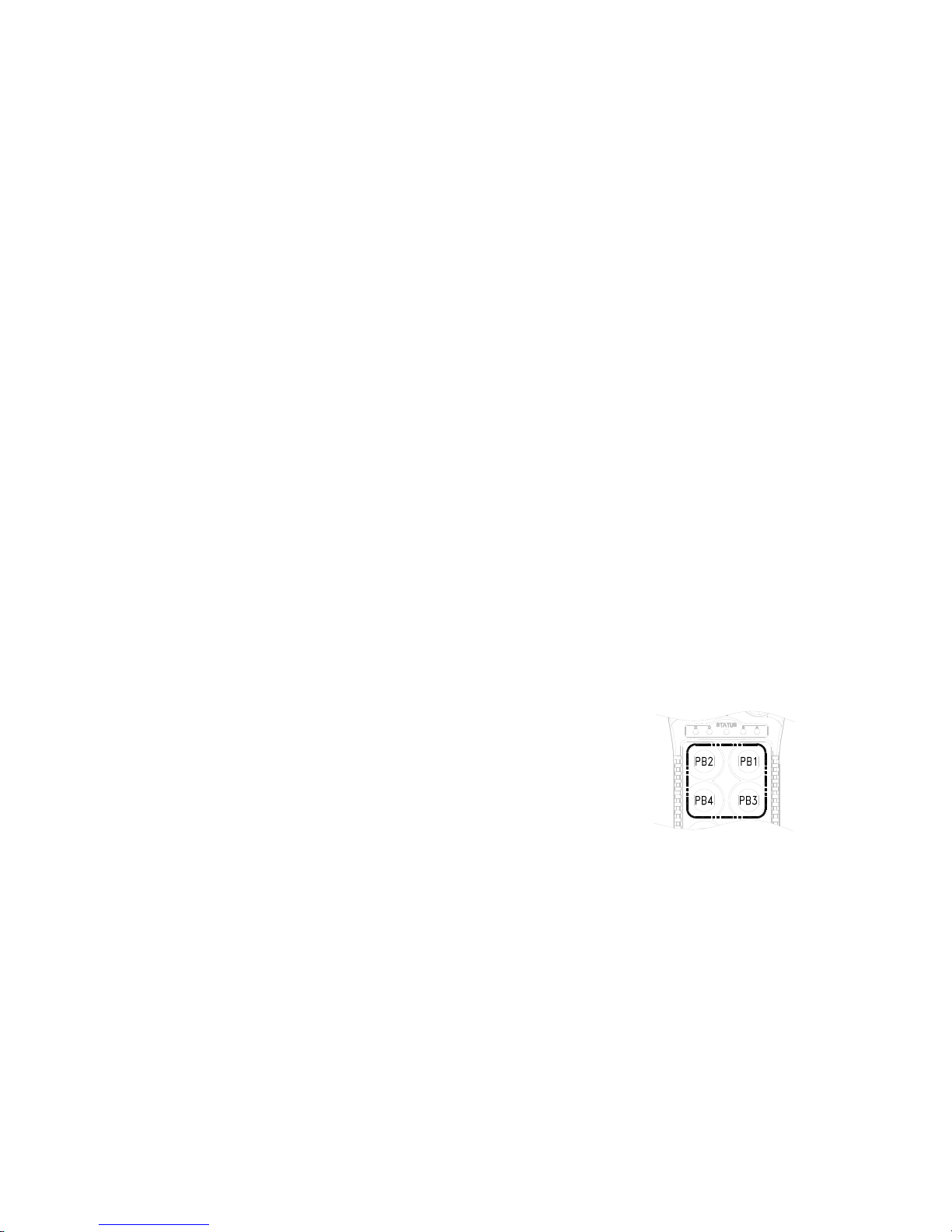
Only PB1 through PB4 are used when using the password function. Numeric
value “1” represents PB1, “2” represents PB2, “3” represents PB3 and “4”
represents PB4.
Setting “1111” → Password function disabled (manufacture preset)
4.9 Program Pushbutton Functions (TX)
1) Make sure the I-Chip is connected to the programmer.
2) Press “→” button to enter Pushbutton Function setting.
3) Press “↑” and “↓” button to change pushbutton function as a whole or…
4) Press “→” button to go to the digit on the far left.
5) Press “↑” and “↓” button to change numeric value.
6) Press “→” button to go to the next digit to the right and repeat step 5.
7) Press “BACK” button to go back to step 3 or 4.
8) Exit Program Pushbutton Functions by pressing the “BACK” button until
the cursor is shown next to “PB FUNC”.
9) Press “↑” and “↓” button to scroll through other Flex EX settings.
The transmitter pushbutton function table on Section 12 Part-A illustrates which numeric value
corresponds to which pushbutton function.
Page 8

Page 7
4.10 Program Function Relay / K26 Relay (RX)
1) Make sure the I-Chip is connected to the programmer.
2) Press “→” button to enter Function Relay setting.
3) Press “↑” and “↓” button to scroll and select.
4) Exit Program Function Relay by pressing the “BACK” button until
the cursor is shown next to “FUNC RLY”.
5) Press “↑” and “↓” button to scroll through other Flex EX settings.
--- : START function only.
NORMAL : START function + AUX with normal momentary output.
TOGGLE : START function + AUX with toggled/latching output.
TOG&E : START function + AUX with toggled/latching output. The relay opens when
STOP button is pressed down and transmitter power off.
EXT : FUNCTION relay works simultaneously with the receiver MAIN relays.
TDM A+B : FUNCTION relay closes when selector switch is rotated to the A+B position
and opens when rotate to A or B positions (tandem monitoring output).
S/P : FUNCTION relay closes when START command is executed and opens only when
transmitter power is turned off.
HORN : FUNCTION relay closes for up to 3 seconds when START command is executed
at transmitter power on and then becomes normal momentary outputs thereafter.
When finished, take out the I-Chip and insert it onto the I-Chip programming port located on
the decoder module to transfer the new setting from the I-Chip to the receiver. Make sure
JP6 jumper is inserted when transferring I-Chip information into the receiver.
4.11 Program Brake Functions (RX)
1) Make sure the I-Chip is connected to the programmer.
2) Press “→” button to enter Brake Function setting.
3) Press “↑” and “↓” button to scroll and select.
4) Exit Program Brake Functions by pressing the “BACK” button until
the cursor is shown next to “BRAKE”.
5) Press “↑” and “↓” button to scroll through other Flex EX settings.
DEMAG 1 : When releasing pushbutton from 2
nd
speed up to 1st speed, the 1
st
speed
output relay will open for up to 1.0 second and then closes again.
DEMAG 2 : When pushbutton is pressed down to 2
nd
speed directly from 0 speed, the 1st
speed output relay will maintain closure for up to 0.4 second before 2
nd
speed
output relay closes. When pushbutton is released from 2nd speed up to 0
speed, the 1
st
speed output relay will maintain closure for up to 0.5 second
before going to 0 speed.
DEMAG 3 : When releasing pushbutton from 2
nd
speed up to 1st speed, both 1st and 2nd
speed output relays are opened. Release pushbutton to 0 speed and then
press down to 1
st
speed to reengage the 1st speed output relay.
P&H : When releasing pushbutton from 2
nd
speed up to 0 speed, the 1
st
speed
output relay will maintain closure for up to 0.1 second before going to 0 speed.
When finished, take out the I-Chip and insert it onto the I-Chip programming port located on
the decoder module to transfer the new Brake setting from the I-Chip to the receiver. Make
sure JP6 jumper is inserted when transferring I-Chip information into the receiver.
Page 9

Page 8
4.12 Program Serial Number (Flex Pro transmitter)
1) Make sure the I-Chip is connected to the programmer.
2) Press “→” button to enter Serial Number setting.
3) Press “↑” and “↓” button to change serial number as a whole or…
4) Press “→” button to go to the 1st digit on the far left of the serial number.
5) Press “↑” and “↓” button to change numeric value.
6) Press “→” button to go to the next digit to the right and repeat step 5.
7) Press “BACK” button to go back to step 3 or 4.
8) Exit Program Serial Number by pressing the “BACK” button until the cursor
is shown next to “TXSN”.
9) Press “↑” and “↓” button to scroll through other Flex EX settings.
4.13 Program Project ID (Flex Pro transmitter)
1) Make sure the I-Chip is connected to the programmer.
2) Press “→” button to enter Project ID setting.
3) Press “↑” and “↓” button to change serial number as a whole or…
4) Press “→” button to go to the 1st digit on the far left of the serial number.
5) Press “↑” and “↓” button to change numeric value.
6) Press “→” button to go to the next digit to the right and repeat step 5.
7) Press “BACK” button to go back to step 3 or 4.
8) Exit Program Serial Number by pressing the “BACK” button until the cursor
is shown next to “PRJT”.
9) Press “↑” and “↓” button to scroll through other Flex EX settings.
4.14 Program CAN ID (Flex Pro transmitter)
1) Make sure the I-Chip is connected to the programmer.
2) Press “→” button to enter CAN ID setting.
3) Press “↑” and “↓” button to change serial number as a whole or…
4) Press “→” button to go to the 1st digit on the far left of the serial number.
5) Press “↑” and “↓” button to change numeric value.
6) Press “→” button to go to the next digit to the right and repeat step 5.
7) Press “BACK” button to go back to step 3 or 4.
8) Exit Program Serial Number by pressing the “BACK” button until the cursor
is shown next to “CAN”.
9) Press “↑” and “↓” button to scroll through other Flex EX settings.
Page 10
Page 9
5. Flex EX2 Models
5.1 Program IR
5.1.1 Transmitter
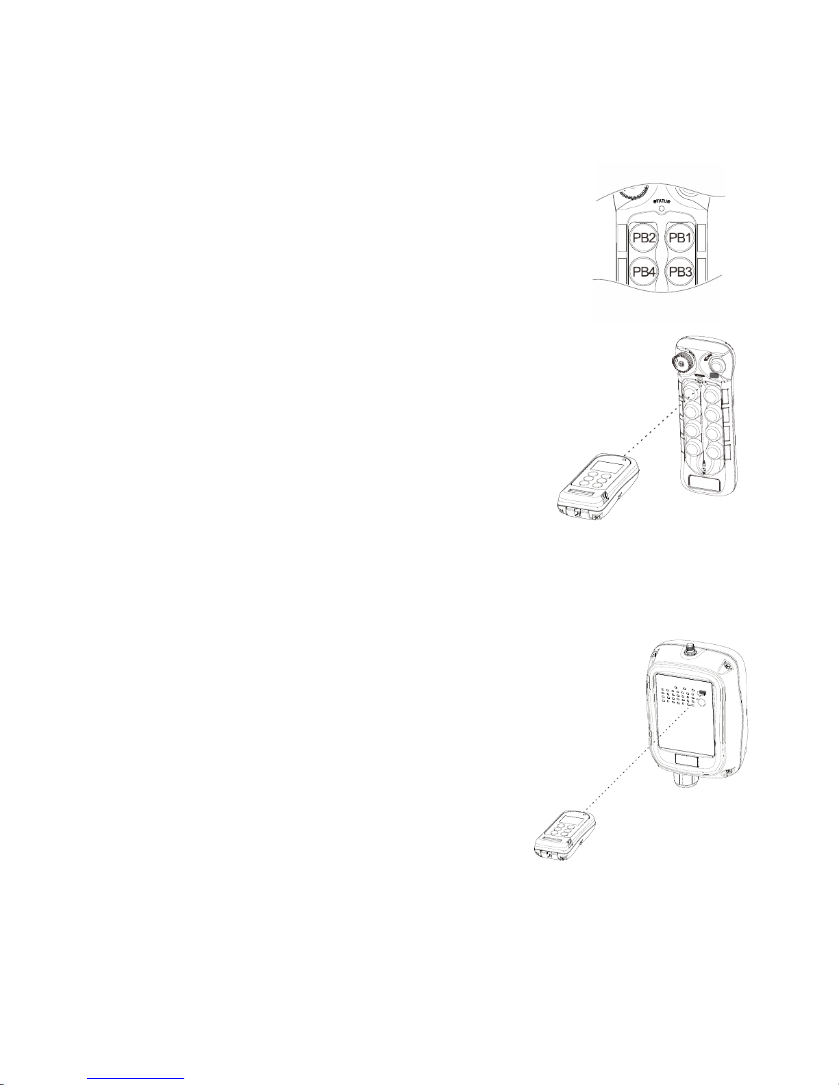
1) Rotate the power switch key to OFF ( 0 ) position.
2) With the STOP button elevated, press and hold PB1
and PB3 at the same time.
3) Rotate the power switch key to ON ( I ) position.
4) Release PB1 and PB3 at the same time. The
transmitter Status LED displays firmware version with
red, green and orange blinks.
5) Press READ button to transfer transmitter info into the
IR programmer. If the screen shows “READ OK”
the transfer is completed.
6) Browse through list of settings by pressing “↑” and
“↓” buttons (see section 5.2 and on).
7) Press WRITE button to transfer the new settings
into the transmitter (transmitter Status LED
constant orange). If the screen shows “WRITE
OK” the transfer is completed (transmitter Status
LED constant green for up to 2 seconds).
8) Exit Program IR by pressing the “BACK” button
until the cursor is shown next to “PROGRAM”.
9) Press “↑” and “↓” button to scroll through other
Flex EX2 settings.
5.1.2 Receiver
1) Power on the receiver with MAIN relays
deactivated (standby mode).
2) Press READ button to transfer receiver info
into the IR programmer. If the screen shows
“READ OK” the transfer is completed.
3) Browse through list of settings by pressing “↑”
and “↓” buttons (see section 5.2 and on).
4) Press WRITE button to transfer the new
settings into the receiver (receiver Status LED
constant orange). If the screen shows “WRITE
OK” the transfer is completed (receiver Status
LED blinks green – standby mode).
5) Exit Program IR by pressing the “BACK” button
until the cursor is shown next to “PREGRAM”.
6) Press “↑” and “↓” button to scroll through other
Flex EX2 settings.
Note: When performing infrared programming make sure the distance between the IR programmer and the
transmitter or receiver is within 10cm.
Page 11

Page 10
5.2 Program Serial Number (TX & RX)
1) Press “→” button to enter Serial Number setting.
2) Press “↑” and “↓” button to change serial number as a whole or…
3) Press “→” button to go to the 1st digit on the far left of the serial number.
4) Press “↑” and “↓” button to change numeric value.
5) Press “→” button to go to the next digit to the right and repeat step 4.
6) Press BACK button to go back to step 2 or 3.
7) Exit Program Serial Number by pressing the “BACK” button until the cursor
is shown next to “S/N:”.
8) Press “↑” and “↓” button to scroll through other Flex EX2 settings.
5.3 Program System Type (TX & RX)
1) Press “→” button to enter System Type setting.
2) Press “↑” and “↓” button to change system type as a whole or…
3) Press “→” button to go to the digit on the far left.
4) Press “↑” and “↓” button to change numeric value.
5) Press “→” button to go to the next digit to the right and repeat step 4.
6) Press BACK button to go back to step 2 or 3.
7) Exit Program System Type by pressing the “BACK” button until the cursor
is shown next to “TYPE:”.
8) Press “↑” and “↓” button to scroll through other Flex EX2 settings.
5.4 Program RS Function (TX & RX)
1) Press “→” button to enter RS Function setting.
2) Press “↑” and “↓” button to change RS Function type number.
3) Press “→” button and then “↑” and “↓” button to select “LOCK” for all Select
buttons interlocked and “UNLOCK” for all Select buttons non-interlocked.
4) Type 06 can further set PB7~PB10 Select buttons and PB11~PB12 Select
buttons “LOCK” or “UNLOCK”.
5) Exit Program RS Function by pressing the “BACK” button until the cursor
is shown next to “RS FUNC:”.
6) Press “↑” and “↓” button to scroll through other Flex EX2 settings.
5.5 Program System Frequency Range (TX & RX)
1) Press “→” button to enter Frequency Range setting.
2) Press “↑” and “↓” button to change frequency range.
3) Exit Program System Frequency Range by pressing the “BACK” button
until the cursor is shown next to “FREQ:”.
4) Press “↑” and “↓” button to scroll through other Flex EX2 settings.
Page 12

Page 11
5.6 Program System Channel (TX & RX)
1) Press “→” button to enter System Channel setting.
2) Press “↑” and “↓” button to change system channel as a whole or…
3) Press “→” button to go to the digit on the left.
4) Press “↑” and “↓” button to change numeric value.
5) Press “→” button to go to the next digit to the right and repeat step 4.
6) Press BACK button to go back to step 2 or 3.
7) Exit Program System Channel by pressing the “BACK” button until the
cursor is shown next to “CHANNEL”.
8) Press “↑” and “↓” button to scroll through other Flex EX2 settings.
5.7 Program RF Power (TX)
1) Press “→” button to enter RF Power setting.
2) Press “↑” and “↓” button to change RF power (0.01mW ~ 10mW).
3) Press “→” button and then “↑” and “↓” button to enable or disable RF
power adjustment via transmitter dipswitch.
4) Exit Program RF Power by pressing the “BACK” button until the cursor is
shown next to “RFpower”.
5) Press “↑” and “↓” button to scroll through other Flex EX2 settings.
5.8 Program Pushbutton Functions (TX)
1) Press “→” button to enter Pushbutton Function setting.
2) Press “↑” and “↓” button to change pushbutton function as a whole or…
3) Press “→” button to go to the digit on the left.
4) Press “↑” and “↓” button to change numeric value.
5) Press “→” button to go to the next digit to the right and repeat step 4.
6) Press BACK button to go back to step 2 or 3.
7) Exit Program Pushbutton Functions by pressing the “BACK” button until
the cursor is shown next to “PB FUNC”.
8) Press “↑” and “↓” button to scroll through other Flex EX2 settings.
The transmitter pushbutton function table on Section 12 Part-B illustrates which numeric value
corresponds to which pushbutton function.
5.9 Program Rotary Switch Functions (TX)
1) Press “→” button to enter Rotary Switch Function setting.
2) Press “↑” and “↓” button to select A/Off/B, A/B/A+B or A/A+B/B rotary
switch sequence.
3) Exit Program Rotary Switch Functions by pressing the “BACK” button until
the cursor is shown next to “SW FUNC”.
4) Press “↑” and “↓” button to scroll through other Flex EX2 settings.
Page 13

Page 12
5.10 Program Transmitter Inactivity Timer (TX)
1) Press “→” button to enter Transmitting Timer setting.
2) Press “↑” and “↓” button to select “_M” for minutes/seconds or “ON” for
constant on.
3) When “ON” is selected, press “→” button and then “↑” and “↓” button to
select “+START” or “+ANY”.
4) When “_M” is selected, press “→” button to go to the digit on the
left and press “↑” and “↓” button to select value. Press “→” button again to
go to the next digit and press “↑” and “↓” button to select value .
5) Press “→” button again to select “M” for minutes or “S” for seconds. Press
“↑” and “↓” button to select.
6) Press “→” button again to select “+START” or “+ANY” selection. Press
“↑” and “↓” button to select.
7) Exit Program Transmitter Timer by pressing the “BACK” button until the
cursor is shown next to “TX TIMER”.
8) Press “↑” and “↓” button to scroll through other Flex EX2 settings.
Transmitter inactivity timer is for setting receiver main relays cutoff time when the transmitter
is not in operation for a certain period of time. When set to 5 minutes (05M), the receiver
main relays are deactivated at 5.0 minutes after last transmitter operation.
Select “ON” means the receiver main relays are activated at all time unless the STOP button
is pressed down or receiver power turned off (inactivity timer disabled).
Select “+START” means after 5 minutes of transmitter inactivity you must press the green
START button to continue operation. Select “+ANY” means after 5 minutes of transmitter
inactivity press any pushbutton to continue operation.
5.11 Program LED1 Feedback (TX)
1) Press “→” button to enter Feedback setting.
2) Press “↑” and “↓” button to select Off, Input number or Output number.
3) When “Input” is selected, press “→” button and then “↑” and “↓” button to
select input number that the external source is connected to (IN1 ~ IN4).
4) When “Output” is selected, press “→” button and then “↑” and “↓” button to
select which output relay to feedback to LED1 (K1 ~ K24).
5) Select “Off” if no feedback is required.
6) Exit Program Feedback by pressing the “BACK” button until the cursor is
shown next to “LED1”.
7) Press “↑” and “↓” button to scroll through other Flex EX2 settings.
5.12 Program LED2 Feedback (TX)
1) Press “→” button to enter Feedback setting.
2) Press “↑” and “↓” button to select Off, Input number or Output number.
3) When “Input” is selected, press “→” button and then “↑” and “↓” button to
select input number that the external source is connected to (IN1 ~ IN4).
4) When “Output” is selected, press “→” button and then “↑” and “↓” button to
select which output relay to feedback to LED2 (K1 ~ K24).
5) Select “Off” if no feedback is required.
6) Exit Program Feedback by pressing the “BACK” button until the cursor is
shown next to “LED2”.
7) Press “↑” and “↓” button to scroll through other Flex EX2 settings.
Page 14

Page 13
5.13 Program LED3 Feedback (TX)
1) Press “→” button to enter Feedback setting.
2) Press “↑” and “↓” button to select Off, Input number or Output number.
3) When “Input” is selected, press “→” button and then “↑” and “↓” button to
select input number that the external source is connected to (IN1 ~ IN4).
4) When “Output” is selected, press “→” button and then “↑” and “↓” button to
select which output relay to feedback to LED3 (K1 ~ K24).
5) Select “Off” if no feedback is required.
6) Exit Program Feedback by pressing the “BACK” button until the cursor is
shown next to “LED3”.
7) Press “↑” and “↓” button to scroll through other Flex EX2 settings.
5.14 Program LED4 Feedback (TX)
1) Press “→” button to enter Feedback setting.
2) Press “↑” and “↓” button to select Off, Input number or Output number.
3) When “Input” is selected, press “→” button and then “↑” and “↓” button to
select input number that the external source is connected to (IN1 ~ IN4).
4) When “Output” is selected, press “→” button and then “↑” and “↓” button to
select which output relay to feedback to LED4 (K1 ~ K24).
5) Select “Off” if no feedback is required.
6) Exit Program Feedback by pressing the “BACK” button until the cursor is
shown next to “LED4”.
7) Press “↑” and “↓” button to scroll through other Flex EX2 settings.
5.15 Program Infrared START (TX)
1) Press “→” button to enter Infrared Start setting.
2) Press “↑” and “↓” button to select Off or IRS.
Select “OFF” to disable infrared START function.
Select “IRS” to enable infrared START function.
3) Exit Program Infrared START by pressing the “BACK” button until the cursor
is shown next to “IR Mode”.
4) Press “↓” button to go to the next Infrared START setting.
5.16 Program Infrared START ID Code (TX)
1) Press “→” button to enter Infrared START ID code setting.
2) Press “↑” and “↓” button to set the 3-digit ID code as a whole or…
3) Press “→” button to go to the digit on the left.
4) Press “↑” and “↓” button to change numeric value.
5) Press “→” button to go to the next digit to the right and repeat step 4.
6) Press BACK button to go back to step 2.
Make sure the infrared module on crane is set to same ID code as the transmitter.
Select “000” disables the ID code function hence any types of infrared modules can be used.
7) Exit Program Infrared START ID Code by pressing the “BACK” button until
the cursor is shown next to “IR ID”.
8) Press “↓” button to go to the next Infrared START setting.
Page 15

Page 14
5.17 Program IRS Time Out (TX)
1) Press “→” button to enter IRS Time Out setting.
2) Press “↑” and “↓” button to select IRS Off or IRS On.
Select “IRS On” if infrared START is required after every transmitter timeout.
Select “IRS Off” if infrared START is not required after every transmitter timeout.
3) Exit Program IRS Time Out by pressing the “BACK” button until the cursor is
shown next to “IRS FUNC”.
4) Press “↑” and “↓” button to scroll through other Flex EX2 settings.
5.18 Program Channel Scanning (RX)
1) Press “→” button to enter Channel Scanning setting.
2) Press “↑” and “↓” button to select number of channel to scan (01~12).
3) Exit Program Channel Scanning by pressing the “BACK” button until the
cursor is shown next to “CH SCAN”.
4) Press “↑” and “↓” button to scroll through other Flex EX2 settings.
Note: Make sure the Channel dipswitch in receiver position 7 and 8 is set to
“11” in order for this to work (refer to manual section 4.2.2.10 or
4.2.2.11).
5.19 Program Function Relay 1 / K25 Relay (RX)
1) Press “→” button to enter Function Relay 1 setting.
2) Press “↑” and “↓” button to scroll and select.
3) Exit Program Function Relay 1 by pressing the “BACK” button until the
cursor is shown next to “FUNC RLY1”.
4) Press “↑” and “↓” button to scroll through other Flex EX2 settings.
--- : START function only.
LV : Function relay closes when receiver voltage is low.
ID : Function relay works simultaneously with all motion commands.
NORMAL : START function + AUX with normal momentary output.
TOGGLE : START function + AUX with toggled/latching output.
TOG&E : START function + AUX with toggled/latching output. The relay opens when
STOP button is pressed down and transmitter power off.
S/P : FUNCTION relay closes when START command is executed and opens only when
transmitter power is turned off.
EXT : FUNCTION relay works simultaneously with the receiver MAIN relays.
TDM A+B : FUNCTION relay closes when selector switch is rotated to the A+B position
and opens when rotate to A or B positions (tandem monitoring output).
HORN : FUNCTION relay closes for up to 3 seconds when START command is initiated
at transmitter power on and then becomes normal momentary outputs thereafter.
G SENSOR : FUNCTION relay closes when Zero-G sensor is triggered (receiver MAIN
relays deactivated) and opens when receiver MAIN relays are reactivated.
RS : For RS system, the function relay works simultaneously with the Select pushbutton.
Page 16

Page 15
5.20 Program Function Relay 2 / K26 Relay (RX)
1) Press “→” button to enter Function Relay 2 setting.
2) Press “↑” and “↓” button to scroll and select.
3) Exit Program Function Relay 2 by pressing the “BACK” button until the
cursor is shown next to “FUNC RLY2”.
4) Press “↑” and “↓” button to scroll through other Flex EX2 settings.
--- : START function only.
LV : Function relay closes when receiver voltage is low.
ID : Function relay works simultaneously with all motion commands.
NORMAL : START function + AUX with normal momentary output.
TOGGLE : START function + AUX with toggled/latching output.
TOG&E : START function + AUX with toggled/latching output. The relay opens when
STOP button is pressed down and transmitter power off.
S/P : FUNCTION relay closes when START command is executed and opens only when
transmitter power is turned off.
EXT : FUNCTION relay works simultaneously with the receiver MAIN relays.
TDM A+B : FUNCTION relay closes when selector switch is rotated to the A+B position
and opens when rotate to A or B positions (tandem monitoring output).
HORN : FUNCTION relay closes for up to 3 seconds when START command is initiated
at transmitter power on and then becomes normal momentary outputs thereafter.
G SENSOR : FUNCTION relay closes when Zero-G sensor is triggered (receiver MAIN
relays deactivated) and opens when receiver MAIN relays are reactivated.
RS : For RS system, the function relay works simultaneously with the Select pushbutton.
5.21 Program Function Relay 3 / K30 Relay (RX)
1) Press “→” button to enter Function Relay 3 setting.
2) Press “↑” and “↓” button to scroll and select.
3) Exit Program Function Relay 3 by pressing the “BACK” button until the
cursor is shown next to “FUNC RLY3”.
4) Press “↑” and “↓” button to scroll through other Flex EX2 settings.
--- : START function only.
LV : Function relay closes when receiver voltage is low.
ID : Function relay works simultaneously with all motion commands.
NORMAL : START function + AUX with normal momentary output.
TOGGLE : START function + AUX with toggled/latching output.
TOG&E : START function + AUX with toggled/latching output. The relay opens when
STOP button is pressed down and transmitter power off.
S/P : FUNCTION relay closes when START command is executed and opens only when
transmitter power is turned off.
EXT : FUNCTION relay works simultaneously with the receiver MAIN relays.
TDM A+B : FUNCTION relay closes when selector switch is rotated to the A+B position
and opens when rotate to A or B positions (tandem monitoring output).
HORN : FUNCTION relay closes for up to 3 seconds when START command is initiated
at transmitter power on and then becomes normal momentary outputs thereafter.
G SENSOR : FUNCTION relay closes when Zero-G sensor is triggered (receiver MAIN
relays deactivated) and opens when receiver MAIN relays are reactivated.
RS : For RS system, the function relay works simultaneously with the Select pushbutton.
Page 17

Page 16
5.22 Program Brake Functions (RX)
1) Press “→” button to enter Brake function setting.
2) Press “↑” and “↓” button to scroll and select.
3) Exit Program Brake Functions by pressing the “BACK” button until
the cursor is shown next to “BRAKE”.
4) Press “↑” and “↓” button to scroll through other Flex EX2 settings.
DEMAG 1 : When releasing pushbutton from 2
nd
speed up to 1st speed, the 1
st
speed
output relay will open for up to 1.0 second and then closes again.
DEMAG 2 : When pushbutton is pressed down to 2
nd
speed directly from 0 speed, the 1st
speed output relay will maintain closure for up to 0.4 second before 2
nd
speed
output relay closes. When pushbutton is released from 2nd speed up to 0
speed, the 1st speed output relay will maintain closure for up to 0.5 second
before going to 0 speed.
DEMAG 3 : When releasing pushbutton from 2
nd
speed up to 1st speed, both 1st and 2nd
speed output relays are opened. Release pushbutton to 0 speed and then
press down to 1
st
speed to reengage the 1st speed output relay.
P&H : When releasing pushbutton from 2
nd
speed up to 0 speed, the 1
st
speed
output relay will maintain closure for up to 0.1 second before going to 0 speed.
5.23 Program MRX Micro Receiver PB type (RX)
1) Press “→” button 2 times to enter PB Type setting.
2) Press “↑” and “↓” button to scroll and select. PB1~4 setting means the
receiver corresponds to PB1~PB4 on the transmitter. PB5~8 means the
receiver corresponds to PB5~PB8 on the transmitter. PB9~12 means the
receiver corresponds to PB9~PB12 on the transmitter. Inline means the
PB number is counted from top to bottom instead of right to left.
3) Exit Program Micro Receiver PB Type by pressing the “BACK” button
until the cursor is shown next to “MICRO RX”.
4) Press “↑” and “↓” button to scroll through other Flex EX2 settings.
Page 18
Page 17
6. Flex 2JX Models
6.1 Program I-Chip
When entering the 2JX model the first selection shown on the screen is
“Program I-Chip” or “Program IR”. Use the “↑” and “↓” buttons to scroll
through various Flex 2JX settings or press “→” button to enter “Program IChip” or “Program IR”. Then press “↑” and “↓” button to select.
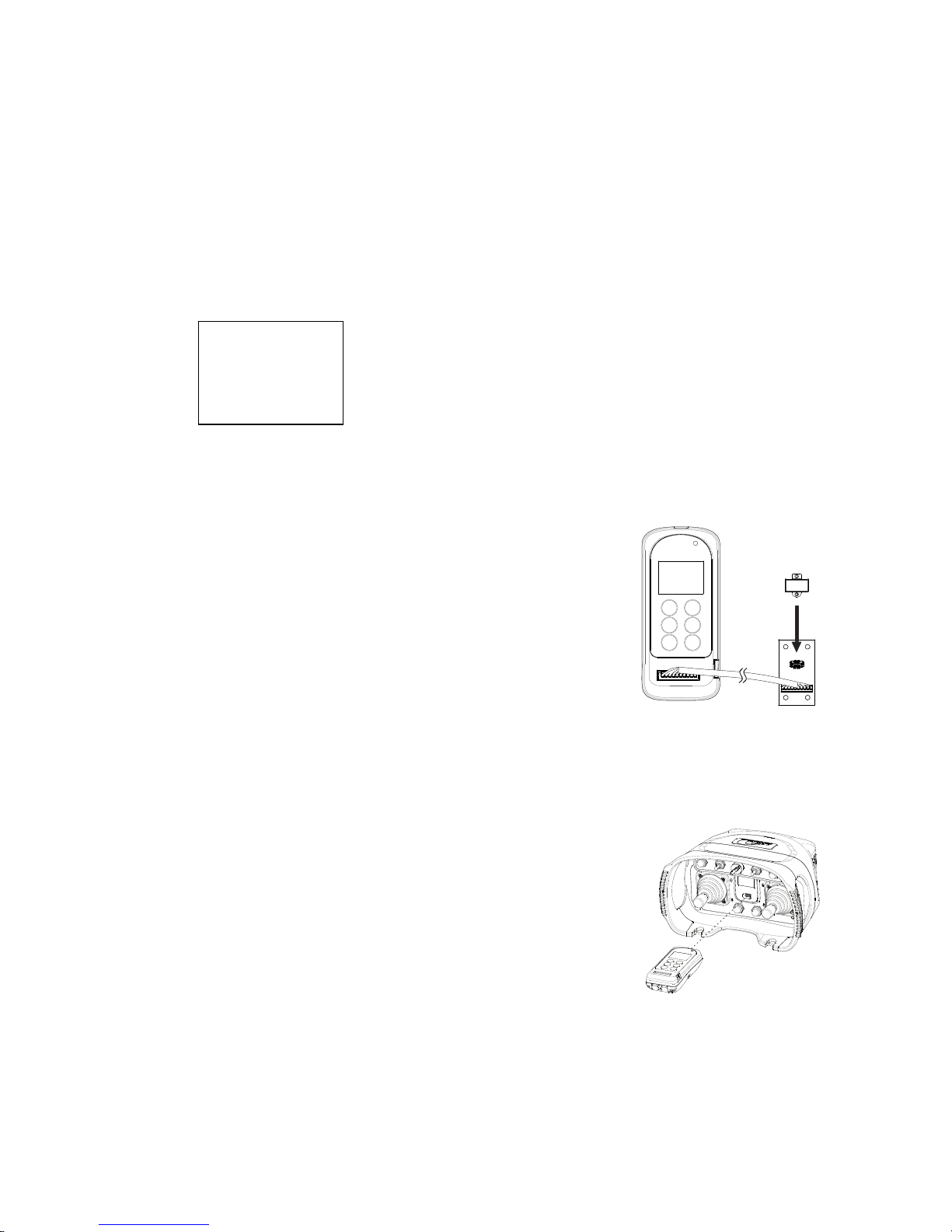
Program I-Chip:
1) Make sure the I-Chip is connected to the programmer.
2) Press “READ” button to store the I-Chip
information into the programmer. If the screen
shows “READ OK” the transfer is completed.
3) Press “WRITE” button to transfer the stored I Chip information into the I-Chip. If the screen
shows “WRITE OK” the transfer is completed.
4) Press “→” button to format the I-Chip, press
“→” button again to execute. If the screen shows
“FORMAT OK” the format is completed.
5) Exit I-Chip programming by pressing the “BACK”
button until the cursor is shown next to “Program”.
6) Press “↑” and “↓” button to scroll through other Flex 2JX settings.
Program IR (infrared):
1) Make sure the transmitter is turned on.
2) Press “READ” button to store the transmitter info
into the programmer. If the screen shows
“READ OK” the transfer is completed.
3) Press “WRITE” button to transfer the stored info
into the transmitter. If the screen shows
“WRITE OK” the transfer is completed. The
transmitter will restart automatically after 2 seconds.
4) Exit Program IR by pressing the “BACK” button until
the cursor is shown next to “Program”.
5) Press “↑” and “↓” button to scroll through other Flex 2JX settings.
Note: When performing infrared programming make sure the distance between the
programmer and the transmitter is within 10cm.
>PROGRAM
I-CHIP
FORMAT
Page 19

Page 18
6.2 Program Serial Number (TX & RX)
1) Make sure the I-Chip is connected to the programmer.
2) Press “→” button to enter Serial Number setting.
3) Press “↑” and “↓” button to change serial number as a whole or…
4) Press “→” button to go to the 1st digit on the far left of the serial number.
5) Press “↑” and “↓” button to change numeric value.
6) Press “→” button to go to the next digit to the right and repeat step 5.
7) Press “BACK” button to go back to step 3 or 4.
8) Exit Program Serial Number by pressing the “BACK” button until the cursor
is shown next to “S/N”.
9) Press “↑” and “↓” button to scroll through other Flex 2JX settings.
When finished, make sure to transfer the newly selected serial number to the receiver.
6.3 Program System Type (TX & RX)
System Type is associated with functions such as tandem operation,
random access operation, multi-receiver operation, etc... Please do not
alter the factory settings unless authorized to do so.
6.4 Program System Frequency Range (TX & RX)
1) Make sure the I-Chip is connected to the programmer.
2) Press “→” button to enter System Frequency Range setting.
3) Press “↑” and “↓” button to change frequency range.
4) Exit Program System Frequency Range by pressing the “BACK” button
until the cursor is shown next to “FREQ:”.
5) Press “↑” and “↓” button to scroll through other Flex 2JX settings.
When changing the frequency range table in I-Chip make sure the transmitting and receiving
RF boards are also changed accordingly.
6.5 Program System Channel (TX & RX)
1) Make sure the I-Chip is connected to the programmer.
2) Press “→” button to enter System Channel setting.
3) Press “↑” and “↓” button to change system channel as a whole or…
4) Press “→” button to go to the digit on the left.
5) Press “↑” and “↓” button to change numeric value.
6) Press “→” button to go to the next digit to the right and repeat step 5
7) Press “BACK” button to go back to step 3 or 4.
8) Exit Program System Channel by pressing the “BACK” button until the
cursor is shown next to “CHANNEL”.
9) Press “↑” and “↓” button to scroll through other Flex 2JX settings.
When transmitter channel is changed make sure the receiver channel is also set to the
newly selected channel.
Page 20

Page 19
6.6 Program Transmitter Inactivity Timer (TX)
1) Make sure the I-Chip is connected to the programmer.
2) Press “→” button to enter Transmitting Timer setting.
3) Press “↑” and “↓” button to select between “__M__S” and “ON”. “__M__S”
represents Minutes and Seconds and “ON” represents constant ON.
4) When “__M__S” is selected, press “→” button to go to the 1st digit on the
far left and press “↑” and “↓” button to change numeric value (number
0~6). Then press “→” button to go to the next digit and press “↑” and “↓”
button to change numeric value (number 0~9). The first 2 digits are the
Minutes value (M). Repeat the same process for the Seconds value (S).
5) Press “→” button to select START button or ANY button activation after
transmitter timeout or after transmitter inactivity.
6) Press “↑” and “↓” button to select.
7) Press BACK button to go back to step 3 or 4.
8) Exit Program Transmitter Timer by pressing the “BACK” button until the
cursor is shown next to “TX TIMER”.
9) Press “↑” and “↓” button to scroll through other Flex 2JX settings.
Transmitter inactivity timer is for setting receiver main relays cutoff time when the transmitter
is not in operation for a certain period of time. When set to 5 minutes (05M00S), the receiver
main relays are deactivated at 5.0 minutes after last transmitter operation.
Select “ON” means the receiver main relays are activated at all time unless the e-stop button
is pressed down, receiver power turned off, or when the transmitter power is switched off
(inactivity time disabled).
Select “+START” means after 5 minutes of transmitter inactivity you must press the green
START button to continue operation. Select “+ANY” means after 5 minutes of transmitter
inactivity operate the joysticks or buttons (not switches) to continue operation.
6.7 Program Transmitter RF Power (TX)
1) Make sure the I-Chip is connected to the programmer.
2) Press “→” button to enter RF Power setting.
3) Press “↑” and “↓” button to change RF power (0.1mW ~ 10mW).
4) Exit Program RF Power by pressing the “BACK” button until the cursor is
shown next to “RFpower”.
5) Press “↑” and “↓” button to scroll through other Flex 2JX settings.
6.8 Program Infrared (IR) Modes (TX)
1) Make sure the I-Chip is connected to the programmer.
2) Press “→” button to enter Infrared Mode setting.
3) Press “↑” and “↓” button to scroll and select.
Select “OFF” to disable infrared function.
Select “IRS” to enable infrared START function.
Select “IRL” to enable infrared range limiting function.
4) Exit Program IR Mode by pressing the “BACK” button until the cursor is
shown next to “IR Mode”.
5) Press “↑” and “↓” button to scroll through other Flex 2JX settings.
Page 21

Page 20
6.9 Program Infrared (IR) Identification Number (TX)
1) Make sure the I-Chip is connected to the programmer.
2) Press “→” button to enter Infrared ID setting.
3) Press “↑” and “↓” button to change IR_ID as a whole or…
4) Press “→” button to go to the digit on the far left.
5) Press “↑” and “↓” button to change numeric value.
6) Press “→” button to go to the next digit to the right and repeat step 5.
7) Press BACK button to go back to step 3 or 4.
8) Exit Program Infrared ID by pressing the “BACK” button until the cursor is
shown next to “IR_ID”.
9) Press “↑” and “↓” button to scroll through other Flex 2JX settings.
Make sure the infrared module on crane is set to same ID code as the transmitter.
Select “000” disables the ID code function hence any types of infrared modules can be used.
6.10 Program IRS Time Out Function (TX)
1) Make sure the I-Chip is connected to the programmer.
2) Press “→” button to enter IRS Time Out setting.
3) Press “↑” and “↓” button to scroll and select between IRS On and IRS Off.
4) Press “→” button to go to the digit on the far left.
5) Press “↑” and “↓” button to change numeric value.
6) Press “→” button to go to the next digit to the right and repeat step 5
7) Press BACK button to go back to step 3 or 4.
8) Exit Program IRS Time Out Function by pressing the “BACK” button until
the cursor is shown next to “IRS FUNC”.
9) Press “↑” and “↓” button to scroll through other Flex 2JX settings.
Select “IRS ON” if infrared START is required after every transmitter timeout.
Select “IRS OFF” if infrared START is not required after every transmitter timeout.
6.11 Program Tilt Function (TX)
1) Make sure the I-Chip is connected to the programmer.
2) Press “→” button to enter Tilt setting.
3) Press “↑” and “↓” button to scroll and select between Off, 1.0S and 0.5S.
4) Exit Program Tilt Function by pressing the “BACK” button until the cursor is
shown next to “TILT”.
5) Press “↑” and “↓” button to scroll through other Flex 2JX settings.
When TILT function is set to 0.5s (more sensitive) or 1.0s (less sensitive), the receiver mains
are disconnected (opened) when the transmitter is tilted for more than 35~40 degrees. Select
OFF disables the TILT function.
Page 22

Page 21
6.12 Program LX Joystick Function (TX)
1) Make sure the I-Chip is connected to the programmer.
2) Press “→” button to enter LX Joystick setting.
3) Press “↑” and “↓” button to scroll and select between None, Analog, 1-step,
2-step, 3-step, 4-step and 5-step.
4) Exit Program LX Function by pressing the “BACK” button until the cursor is
shown next to “LX FUNC”.
5) Press “↑” and “↓” button to scroll through other Flex 2JX settings.
Set each joystick’s number of steps and output type (analog-stepless or digital-stepped)
according to the hardware installed.
6.13 Program LY Joystick Function (TX)
1) Make sure the I-Chip is connected to the programmer.
2) Press “→” button to enter LY Joystick setting.
3) Press “↑” and “↓” button to scroll and select between None, Analog, 1-step,
2-step, 3-step, 4-step and 5-step.
4) Exit Program LY Function by pressing the “BACK” button until the cursor is
shown next to “LY FUNC”.
5) Press “↑” and “↓” button to scroll through other Flex 2JX settings.
Set each joystick’s number of steps and output type (analog-stepless or digital-stepped)
according to the hardware installed.
6.14 Program RX Joystick Function (TX)
1) Make sure the I-Chip is connected to the programmer.
2) Press “→” button to enter RX Joystick setting.
3) Press “↑” and “↓” button to scroll and select between None, Analog, 1-step,
2-step, 3-step, 4-step and 5-step.
4) Exit Program RX Function by pressing the “BACK” button until the cursor
is shown next to “RX FUNC”.
5) Press “↑” and “↓” button to scroll through other Flex 2JX settings.
Set each joystick’s number of steps and output type (analog-stepless or digital-stepped)
according to the hardware installed.
6.15 Program RY Joystick Function (TX)
1) Make sure the I-Chip is connected to the programmer.
2) Press “→” button to enter RY Joystick setting.
3) Press “↑” and “↓” button to scroll and select between None, Analog, 1-step,
2-step, 3-step, 4-step and 5-step.
4) Exit Program RY Function by pressing the “BACK” button until the cursor is
shown next to “RY FUNC”.
5) Press “↑” and “↓” button to scroll through other Flex 2JX settings.
Set each joystick’s number of steps and output type (analog-stepless or digital-stepped)
according to the hardware installed.
Page 23

Page 22
6.16 Program SW1 Function (TX)
1) Make sure the I-Chip is connected to the programmer.
2) Press “→” button to enter SW1 setting.
3) Press “↑” and “↓” button to scroll and select between settings.
4) Exit Program SW1 Function by pressing the “BACK” button until the cursor is
shown next to “SW1FUNC”.
5) Press “↑” and “↓” button to scroll through other Flex 2JX settings.
Button: Select “NORMAL” for momentary output relay contact and “TOGGLE” for transmitter
toggled output relay contact. Select “A→B” or “0→A→B” or “A→B→AB” or “0→A→B→AB” for
Select A/B, off/A/B, A/B/AB or off/A/B/AB output relay contacts. Select “A→B→C” or “0→A→B→C”
adds the 3
rd
output for Select A/B/C output relay contacts (see section 6.25~6.26).
Rocker Switch: Select “NORMAL” for 2-stage On-On or 3-stage On-Off-On output relay contacts.
Select “SW A→AB→B” for Select A/A+B/B output relay contacts. Select “A→B→C” or
“0→A→B→C” adds the 3
rd
output for Select A/B/C output relay contacts (see section 6.25~6.26).
Important: If SW1 is set to one of the above settings then the SW1 output relay function in
receiver must set to “NORMAL” or “ABUS” (Reversed Logic A/A+B/B).
6.17 Program SW2 Function (TX)
1) Make sure the I-Chip is connected to the programmer.
2) Press “→” button to enter SW2 setting.
3) Press “↑” and “↓” button to scroll and select between settings.
4) Exit Program SW2 Function by pressing the “BACK” button until the cursor is
shown next to “SW2FUNC”.
5) Press “↑” and “↓” button to scroll through other Flex 2JX settings.
Button: Select “NORMAL” for momentary output relay contact and “TOGGLE” for transmitter
toggled output relay contact. Select “A→B” or “0→A→B” or “A→B→AB” or “0→A→B→AB” for
Select A/B, off/A/B, A/B/AB or off/A/B/AB output relay contacts. Select “A→B→C” or “0→A→B→C”
adds the 3
rd
output for Select A/B/C output relay contacts (see section 6.25~6.26).
Rocker Switch: Select “NORMAL” for 2-stage On-On or 3-stage On-Off-On output relay contacts.
Select “SW A→AB→B” for Select A/A+B/B output relay contacts. Select “A→B→C” or
“0→A→B→C” adds the 3
rd
output for Select A/B/C output relay contacts (see section 6.25~6.26).
Important: If SW2 is set to one of the above settings then the SW1 output relay function in
receiver must set to “NORMAL” or “ABUS” (Reversed Logic A/A+B/B).
6.18 Program SW3 Function (TX)
1) Make sure the I-Chip is connected to the programmer.
2) Press “→” button to enter SW3 setting.
3) Press “↑” and “↓” button to scroll and select between settings.
4) Exit Program SW3 Function by pressing the “BACK” button until the cursor is
shown next to “SW3FUNC”.
5) Press “↑” and “↓” button to scroll through other Flex 2JX settings.
Rotary Switch: Select “NORMAL” for 2-stage On-On or 3-stage On-Off-On output relay contacts.
Select “SW A→AB→B” for Select A/A+B/B output relay contacts. Select “A→B→C” or
“0→A→B→C” adds the 3
rd
output for Select A/B/C output relay contacts (see section 6.25~6.26).
Important: If SW3 is set to one of the above settings then the SW3 output relay function in
receiver must set to “NORMAL” or “ABUS” (Reversed Logic A/A+B/B).
Page 24

Page 23
6.19 Program SW4 Function (TX)
1) Make sure the I-Chip is connected to the programmer.
2) Press “→” button to enter SW4 setting.
3) Press “↑” and “↓” button to scroll and select between settings.
4) Exit Program SW4 Function by pressing the “BACK” button until the cursor is
shown next to “SW4FUNC”.
5) Press “↑” and “↓” button to scroll through other Flex 2JX settings.
Button: Select “NORMAL” for momentary output relay contact and “TOGGLE” for transmitter
toggled output relay contact. Select “A→B” or “0→A→B” or “A→B→AB” or “0→A→B→AB” for
Select A/B, off/A/B, A/B/AB or off/A/B/AB output relay contacts. Select “A→B→C” or “0→A→B→C”
adds the 3
rd
output for Select A/B/C output relay contacts (see section 6.25~6.26).
Rocker Switch: Select “NORMAL” for 2-stage On-On or 3-stage On-Off-On output relay contacts.
Select “SW A→AB→B” for Select A/A+B/B output relay contacts. Select “A→B→C” or
“0→A→B→C” adds the 3
rd
output for Select A/B/C output relay contacts (see section 6.25~6.26).
Important: If SW4 is set to one of the above settings then the SW1 output relay function in
receiver must set to “NORMAL” or “ABUS” (Reversed Logic A/A+B/B).
6.20 Program SW5 Function (TX)
1) Make sure the I-Chip is connected to the programmer.
2) Press “→” button to enter SW5 setting.
3) Press “↑” and “↓” button to scroll and select between settings.
4) Exit Program SW5 Function by pressing the “BACK” button until the cursor is
shown next to “SW5FUNC”.
5) Press “↑” and “↓” button to scroll through other Flex 2JX settings.
Button: Select “NORMAL” for momentary output relay contact and “TOGGLE” for transmitter
toggled output relay contact. Select “A→B” or “0→A→B” or “A→B→AB” or “0→A→B→AB” for
Select A/B, off/A/B, A/B/AB or off/A/B/AB output relay contacts. Select “A→B→C” or “0→A→B→C”
adds the 3
rd
output for Select A/B/C output relay contacts (see section 6.25~6.26).
Rocker Switch: Select “NORMAL” for 2-stage On-On or 3-stage On-Off-On output relay contacts.
Select “SW A→AB→B” for Select A/A+B/B output relay contacts. Select “A→B→C” or
“0→A→B→C” adds the 3
rd
output for Select A/B/C output relay contacts (see section 6.25~6.26).
Important: If SW5 is set to one of the above settings then the SW1 output relay function in
receiver must set to “NORMAL” or “ABUS” (Reversed Logic A/A+B/B).
6.21 Program SW6 Function (TX)
1) Make sure the I-Chip is connected to the programmer.
2) Press “→” button to enter SW6 setting.
3) Press “↑” and “↓” button to scroll and select between settings.
4) Exit Program SW6 Function by pressing the “BACK” button until the cursor is
shown next to “SW6FUNC”.
5) Press “↑” and “↓” button to scroll through other Flex 2JX settings.
Button: Select “NORMAL” for normal momentary relay output and “TOGGLE” for transmitter
toggled relay output.
Page 25

Page 24
6.22 Program SW7 Function (TX)
1) Make sure the I-Chip is connected to the programmer.
2) Press “→” button to enter SW7 setting.
3) Press “↑” and “↓” button to scroll and select between settings.
4) Exit Program SW7 Function by pressing the “BACK” button until the cursor is
shown next to “SW7FUNC”.
5) Press “↑” and “↓” button to scroll through other Flex 2JX settings.
Button: Select “NORMAL” for normal momentary relay output and “TOGGLE” for transmitter
toggled relay output.
6.23 Program Channel Scanning Function (RX)
1) Make sure the I-Chip is connected to the programmer.
2) Press “→” button to enter Channel Scanning setting.
3) Press “↑” and “↓” button to scroll and select between settings.
4) Exit Program Channel Scanning Function by pressing the “BACK” button until
the cursor is shown next to “CH SCAN”.
5) Press “↑” and “↓” button to scroll through other Flex 2JX settings.
Select “01” the receiver only scans the channel set on the receiver.
Select “02” the receiver scans the channel set on the receiver plus the next channel up (scans
channel N and channel N+1).
Select “03” the receiver scans the channel set on the receiver plus the next two channels
up (scans channel N, channel N+1 and channel N+2).
Select “ALL” the receiver scans all 62 channels.
6.24 Program MAIN Relay Function (RX)
1) Make sure the I-Chip is connected to the programmer.
2) Press “→” button to enter MAIN Relay setting.
3) Press “↑” and “↓” button to scroll and select between Test and Normal.
4) Exit Program MAIN Relay Function by pressing the “BACK” button until
the cursor is shown next to “MAIN RLY”.
5) Press “↑” and “↓” button to scroll through other Flex 2JX settings.
Select “NORMAL” for normal operation (receiver mains and all other outputs enabled).
Select “TEST” for system testing (receiver mains disabled and all other outputs enabled).
Page 26

Page 25
6.25 Program Function Relay 1 (RX)
1) Make sure the I-Chip is connected to the programmer.
2) Press “→” button to enter Function Relay 1 setting.
3) Press “↑” and “↓” button to scroll and select between settings.
4) Exit Program Function Relay 1 by pressing the “BACK” button until
the cursor is shown next to “FUNC RLY1”.
5) Press “↑” and “↓” button to scroll through other Flex 2JX settings.
Select “LV” for receiver low voltage external warning output.
Select “ID” for receiver ID output (works simultaneously with all joystick motions and
interlocking momentary contacts).
Select “NORMAL” the output relay becomes momentary contact when START button is
pressed.
Select “TOGGLE” the output relay becomes toggled contact when START button is pressed.
Select “TOGGLE&E” the output relay becomes toggled contact affected by the e-stop
command (output relay opens when e-stop button is pressed).
Select “EXT” the output relay works simultaneously with the receiver mains.
Select “S/P” the output relay closes when the green START button is pressed and opens
only when transmitter power is switched off, not e-stop pressed.
Select “TDM A+B” the output relay closes when the 3-stage tandem rotary key switch on
the SW3 slot is rotated to A+B position for dual crane A+B tandem operation.
Select “SW1 1+2… SW5 1+2” the output relay closes when a 3-stage rocker switch, a 3stage rotary switch or a 3-stage A/B/A+B button on SW1 ~ SW5 slot is rotated to A+B
position for dual hoist/trolley A+B tandem operation. Only 1 switch or button can be
assigned to each Function relay.
Select “HORN” the output relay closes for up to 3 seconds when the green START button is
pressed after every transmitter power on and then becomes a momentary contact thereafter.
Select “SW1~5 ABC” adds the 3
rd
outputs relay for button or switch A→B→C selection (see
section 6.16~6.20).
Page 27

Page 26
6.26 Program Function Relay 2 (RX)
1) Make sure the I-Chip is connected to the programmer.
2) Press “→” button to enter Function Relay 2 setting.
3) Press “↑” and “↓” button to scroll and select between settings.
4) Exit Program Function Relay 2 by pressing the “BACK” button until
the cursor is shown next to “FUNC RLY2”.
5) Press “↑” and “↓” button to scroll through other Flex 2JX settings.
Select “LV” for receiver low voltage external warning output.
Select “ID” for receiver ID output (works simultaneously with all joystick motions and
interlocking momentary contacts).
Select “NORMAL” the output relay becomes momentary contact when START button is
pressed.
Select “TOGGLE” the output relay becomes toggled contact when START button is pressed.
Select “TOGGLE&E” the output relay becomes toggled contact affected by the e-stop
command (output relay opens when e-stop button is pressed).
Select “EXT” the output relay works simultaneously with the receiver mains.
Select “S/P” the output relay closes when the green START button is pressed and opens
only when transmitter power is switched off, not e-stop pressed.
Select “TDM A+B” the output relay closes when the 3-stage tandem rotary key switch on
the SW3 slot is rotated to A+B position for dual crane A+B tandem operation.
Select “SW1 1+2… SW5 1+2” the output relay closes when a 3-stage rocker switch, a 3stage rotary switch or a 3-stage A/B/A+B button on SW1 ~ SW5 slot is rotated to A+B
position for dual hoist/trolley A+B tandem operation. Only 1 switch or button can be
assigned to each Function relay.
Select “HORN” the output relay closes for up to 3 seconds when the green START button is
pressed after every transmitter power on and then becomes a momentary contact thereafter.
Select “SW1~5 ABC” adds the 3
rd
outputs relay for button or switch A→B→C selection (see
section 6.16~6.20).
Page 28

Page 27
6.27 Program LX Output Relay (RX)
Below chart and settings are various types of shared (F/R) and separate (F or R) acceleration
relay closure at 1
st
, 2nd, 3rd, 4th and 5th steps.
Output
Relay
Type
LY
LX
RY
RX
K2
K9
K16
K23
K3
K10
K17
K24
K4
K11
K18
K25
K5
K12
K19
K26
K6
K13
K20
K27
K7
K14
K21
K28
01
at 1st Step
at 2
nd
Step
at 3
rd
Step
at 4
th
Step
at 5
th
Step
F1
F1
F1
F1
F1
or R1
or R1
or R1
or R1
or R1
F/R2
F/R2
F/R2
F/R2
F/R3
F/R3
F/R3
F/R4
F/R4
F/R5
02
at 1st Step
at 2
nd
Step
at 3
rd
Step
at 4
th
Step
at 5
th
Step
F1
F1
F1
F1
F1
or R1
or R1
or R1
or R1
or R1
F/R2
F/R3
F/R4
F/R5
03
at 1
st
Step
at 2
nd
Step
at 3
rd
Step
at 4
th
Step
F
F
F
F
or R
or R
or R
or R
F/R1
F/R1
F/R1
F/R1
F/R2
F/R2
F/R2
F/R3
F/R3
F/R4
04
at 1
st
Step
at 2
nd
Step
at 3
rd
Step
at 4
th
Step
F
F
F
F
or R
or R
or R
or R
F/R1
F/R2
F/R3
F/R4
05
at 1
st
Step
at 2
nd
Step
at 3
rd
Step
F1
F1
F1
or R1
or R1
or R1
F2
F2
or R2
or R2
F3
or R3
06
at 1
st
Step
at 2
nd
Step
at 3
rd
Step
F1 or R1
F2
or R2
F3
or R3
LY → Left Joystick Y axis LX → Left Joystick X axis RY → Right Joystick Y axis RY → Right Joystick X axis
F → Forward F1 → Forward 1
st
step F2 → Forward 2nd step F3 → Forward 3rd step F4 → Forward 4
th
step
F5 → Forward 5
th
step R → Reverse R1 → Reverse 1st step R2 → Reverse 2nd step R3 → Reverse 3
rd
step
R4 → Reverse 4
th
step R5 → Reverse 5th step F/R1 → Forward/Reverse shared 1
st
step
F/R2 → Forward/Reverse shared 2
nd
step F/R3 → Forward/Reverse shared 3
rd
step
F/R4 → Forward/Reverse shared 4
th
step F/R5 → Forward/Reverse shared 5
th
step
K8 → 0-step relays can be set to NO (normal open) or NC (normal close) contact.
1) Make sure the I-Chip is connected to the programmer.
2) Press “→” button to enter LX Output Relay setting.
3) Press “↑” and “↓” button to select output relay type (see above chart type
01~06) and K8 relay type (NC-Normal Open or NO-Normal Close).
4) Press “→” button to enter and press “↑” and “↓” button to scroll and select
5) Press “BACK” button to go back to step 3.
6) Exit Program Channel Scanning Function by pressing the “BACK” button until
the cursor is shown next to “LX RLY”.
7) Press “↑” and “↓” button to scroll through other Flex 2JX settings.
Page 29

Page 28
6.28 Program LY Output Relay (RX)
Below chart and settings are various types of shared (F/R) and separate (F or R) acceleration
relay closure at 1
st
, 2nd, 3rd, 4th and 5th steps.
Output
Relay
Type
LY
LX
RY
RX
K2
K9
K16
K23
K3
K10
K17
K24
K4
K11
K18
K25
K5
K12
K19
K26
K6
K13
K20
K27
K7
K14
K21
K28
01
at 1st Step
at 2
nd
Step
at 3
rd
Step
at 4
th
Step
at 5
th
Step
F1
F1
F1
F1
F1
or R1
or R1
or R1
or R1
or R1
F/R2
F/R2
F/R2
F/R2
F/R3
F/R3
F/R3
F/R4
F/R4
F/R5
02
at 1st Step
at 2
nd
Step
at 3
rd
Step
at 4
th
Step
at 5
th
Step
F1
F1
F1
F1
F1
or R1
or R1
or R1
or R1
or R1
F/R2
F/R3
F/R4
F/R5
03
at 1
st
Step
at 2
nd
Step
at 3
rd
Step
at 4
th
Step
F
F
F
F
or R
or R
or R
or R
F/R1
F/R1
F/R1
F/R1
F/R2
F/R2
F/R2
F/R3
F/R3
F/R4
04
at 1
st
Step
at 2
nd
Step
at 3
rd
Step
at 4
th
Step
F
F
F
F
or R
or R
or R
or R
F/R1
F/R2
F/R3
F/R4
05
at 1
st
Step
at 2
nd
Step
at 3
rd
Step
F1
F1
F1
or R1
or R1
or R1
F2
F2
or R2
or R2
F3
or R3
06
at 1
st
Step
at 2
nd
Step
at 3
rd
Step
F1 or R1
F2
or R2
F3
or R3
LY → Left Joystick Y axis LX → Left Joystick X axis RY → Right Joystick Y axis RY → Right Joystick X axis
F → Forward F1 → Forward 1
st
step F2 → Forward 2nd step F3 → Forward 3rd step F4 → Forward 4
th
step
F5 → Forward 5
th
step R → Reverse R1 → Reverse 1st step R2 → Reverse 2nd step R3 → Reverse 3
rd
step
R4 → Reverse 4
th
step R5 → Reverse 5th step F/R1 → Forward/Reverse shared 1
st
step
F/R2 → Forward/Reverse shared 2
nd
step F/R3 → Forward/Reverse shared 3
rd
step
F/R4 → Forward/Reverse shared 4
th
step F/R5 → Forward/Reverse shared 5
th
step
K1 → 0-step relays can be set to NO (normal open) or NC (normal close) contact.
1) Make sure the I-Chip is connected to the programmer.
2) Press “→” button to enter LY Output Relay setting.
3) Press “↑” and “↓” button to select output relay type (see above chart type
01~06) and K1 relay type (NC-Normal Open or NO-Normal Close).
4) Press “→” button to enter and press “↑” and “↓” button to scroll and select.
5) Press “BACK” button to go back to step 3.
6) Exit Program Channel Scanning Function by pressing the “BACK” button until
the cursor is shown next to “LY RLY”.
7) Press “↑” and “↓” button to scroll through other Flex 2JX settings.
Page 30

Page 29
6.29 Program RX Output Relay (RX)
Below chart and settings are various types of shared (F/R) and separate (F or R) acceleration
relay closure at 1
st
, 2nd, 3rd, 4th and 5th steps.
Output
Relay
Type
LY
LX
RY
RX
K2
K9
K16
K23
K3
K10
K17
K24
K4
K11
K18
K25
K5
K12
K19
K26
K6
K13
K20
K27
K7
K14
K21
K28
01
at 1st Step
at 2
nd
Step
at 3
rd
Step
at 4
th
Step
at 5
th
Step
F1
F1
F1
F1
F1
or R1
or R1
or R1
or R1
or R1
F/R2
F/R2
F/R2
F/R2
F/R3
F/R3
F/R3
F/R4
F/R4
F/R5
02
at 1st Step
at 2
nd
Step
at 3
rd
Step
at 4
th
Step
at 5
th
Step
F1
F1
F1
F1
F1
or R1
or R1
or R1
or R1
or R1
F/R2
F/R3
F/R4
F/R5
03
at 1
st
Step
at 2
nd
Step
at 3
rd
Step
at 4
th
Step
F
F
F
F
or R
or R
or R
or R
F/R1
F/R1
F/R1
F/R1
F/R2
F/R2
F/R2
F/R3
F/R3
F/R4
04
at 1
st
Step
at 2
nd
Step
at 3
rd
Step
at 4
th
Step
F
F
F
F
or R
or R
or R
or R
F/R1
F/R2
F/R3
F/R4
05
at 1
st
Step
at 2
nd
Step
at 3
rd
Step
F1
F1
F1
or R1
or R1
or R1
F2
F2
or R2
or R2
F3
or R3
06
at 1
st
Step
at 2
nd
Step
at 3
rd
Step
F1 or R1
F2
or R2
F3
or R3
LY → Left Joystick Y axis LX → Left Joystick X axis RY → Right Joystick Y axis RY → Right Joystick X axis
F → Forward F1 → Forward 1
st
step F2 → Forward 2nd step F3 → Forward 3rd step F4 → Forward 4
th
step
F5 → Forward 5
th
step R → Reverse R1 → Reverse 1st step R2 → Reverse 2nd step R3 → Reverse 3
rd
step
R4 → Reverse 4
th
step R5 → Reverse 5th step F/R1 → Forward/Reverse shared 1
st
step
F/R2 → Forward/Reverse shared 2
nd
step F/R3 → Forward/Reverse shared 3
rd
step
F/R4 → Forward/Reverse shared 4
th
step F/R5 → Forward/Reverse shared 5
th
step
K22 → 0-step relays can be set to NO (normal open) or NC (normal close) contact.
1) Make sure the I-Chip is connected to the programmer.
2) Press “→” button to enter RX Output Relay setting.
3) Press “↑” and “↓” button to select output relay type (see above chart type
01~06) and K22 relay type (NC-Normal Open or NO-Normal Close).
4) Press “→” button to enter and press “↑” and “↓” button to scroll and select.
5) Press “BACK” button to go back to step 3.
6) Exit Program Channel Scanning Function by pressing the “BACK” button until
the cursor is shown next to “RX RLY”.
7) Press “↑” and “↓” button to scroll through other Flex 2JX settings.
Page 31

Page 30
6.30 Program RY Output Relay (RX)
Below chart and settings are various types of shared (F/R) and separate (F or R) acceleration
relay closure at 1
st
, 2nd, 3rd, 4th and 5th steps.
Output
Relay
Type
LY
LX
RY
RX
K2
K9
K16
K23
K3
K10
K17
K24
K4
K11
K18
K25
K5
K12
K19
K26
K6
K13
K20
K27
K7
K14
K21
K28
01
at 1st Step
at 2
nd
Step
at 3
rd
Step
at 4
th
Step
at 5
th
Step
F1
F1
F1
F1
F1
or R1
or R1
or R1
or R1
or R1
F/R2
F/R2
F/R2
F/R2
F/R3
F/R3
F/R3
F/R4
F/R4
F/R5
02
at 1st Step
at 2
nd
Step
at 3
rd
Step
at 4
th
Step
at 5
th
Step
F1
F1
F1
F1
F1
or R1
or R1
or R1
or R1
or R1
F/R2
F/R3
F/R4
F/R5
03
at 1
st
Step
at 2
nd
Step
at 3
rd
Step
at 4
th
Step
F
F
F
F
or R
or R
or R
or R
F/R1
F/R1
F/R1
F/R1
F/R2
F/R2
F/R2
F/R3
F/R3
F/R4
04
at 1
st
Step
at 2
nd
Step
at 3
rd
Step
at 4
th
Step
F
F
F
F
or R
or R
or R
or R
F/R1
F/R2
F/R3
F/R4
05
at 1
st
Step
at 2
nd
Step
at 3
rd
Step
F1
F1
F1
or R1
or R1
or R1
F2
F2
or R2
or R2
F3
or R3
06
at 1
st
Step
at 2
nd
Step
at 3
rd
Step
F1 or R1
F2
or R2
F3
or R3
LY → Left Joystick Y axis LX → Left Joystick X axis RY → Right Joystick Y axis RY → Right Joystick X axis
F → Forward F1 → Forward 1
st
step F2 → Forward 2nd step F3 → Forward 3rd step F4 → Forward 4
th
step
F5 → Forward 5
th
step R → Reverse R1 → Reverse 1st step R2 → Reverse 2nd step R3 → Reverse 3
rd
step
R4 → Reverse 4
th
step R5 → Reverse 5th step F/R1 → Forward/Reverse shared 1
st
step
F/R2 → Forward/Reverse shared 2
nd
step F/R3 → Forward/Reverse shared 3
rd
step
F/R4 → Forward/Reverse shared 4
th
step F/R5 → Forward/Reverse shared 5
th
step
K15 → 0-step relays can be set to NO (normal open) or NC (normal close) contact.
1) Make sure the I-Chip is connected to the programmer.
2) Press “→” button to enter RY Output Relay setting.
3) Press “↑” and “↓” button to select output relay type (see above chart type
01~06) and K8 relay type (NC-Normal Open or NO-Normal Close).
4) Press “→” button to enter and press “↑” and “↓” button to scroll and select.
5) Press “BACK” button to go back to step 3.
6) Exit Program Channel Scanning Function by pressing the “BACK” button until
the cursor is shown next to “RY RLY”.
7) Press “↑” and “↓” button to scroll through other Flex 2JX settings.
Page 32

Page 31
6.31 Program LX Delay (RX)
1) Make sure the I-Chip is connected to the programmer.
2) Press “→” button to enter LX Delay setting.
3) Press “↑” and “↓” button to select delay for ACC (forward motion) and DEC
(reverse motion).
4) Press “→” button to enter and press “↑” and “↓” button to scroll and select.
5) Press “BACK” button to go back to step 3.
6) Exit Program LX Delay by pressing the “BACK” button until the cursor is
shown next to “LX DELAY”.
7) Press “↑” and “↓” button to scroll through other Flex 2JX settings.
6.32 Program LY Delay (RX)
1) Make sure the I-Chip is connected to the programmer.
2) Press “→” button to enter LY Delay setting.
3) Press “↑” and “↓” button to select delay for ACC (forward motion) and DEC
(reverse motion).
4) Press “→” button to enter and press “↑” and “↓” button to scroll and select.
5) Press “BACK” button to go back to step 3.
6) Exit Program LY Delay by pressing the “BACK” button until the cursor is
shown next to “LY DELAY”.
7) Press “↑” and “↓” button to scroll through other Flex 2JX settings.
6.33 Program RX Delay (RX)
1) Make sure the I-Chip is connected to the programmer.
2) Press “→” button to enter RX Delay setting.
3) Press “↑” and “↓” button to select delay for ACC (forward motion) and DEC
(reverse motion).
4) Press “→” button to enter and press “↑” and “↓” button to scroll and select.
5) Press “BACK” button to go back to step 3.
6) Exit Program RX Delay by pressing the “BACK” button until the cursor is
shown next to “RX DELAY”.
7) Press “↑” and “↓” button to scroll through other Flex 2JX settings.
6.34 Program RY Delay (RX)
1) Make sure the I-Chip is connected to the programmer.
2) Press “→” button to enter RY Delay setting.
3) Press “↑” and “↓” button to select delay for ACC (forward motion) and DEC
(reverse motion).
4) Press “→” button to enter and press “↑” and “↓” button to scroll and select.
5) Press “BACK” button to go back to step 3.
6) Exit Program RY Delay by pressing the “BACK” button until the cursor is
shown next to “RY DELAY”.
7) Press “↑” and “↓” button to scroll through other Flex 2JX settings.
Page 33

Page 32
6.35 Program LX Output (RX)
1) Make sure the I-Chip is connected to the programmer.
2) Press “→” button to enter LX Output setting.
3) Press “↑” and “↓” button to scroll between OFF, Voltage, Current and PFM
output setting. Press “→” button to enter.
When Voltage is selected on step 3 above: press “↑” and “↓” button to scroll
between Maximum, Neutral and Minimum value. Press “→” button to enter and
then “↑” and “↓” button to change voltage value. Press “→” button to go to the
next column to the right and press “↑” and “↓” button to change voltage value, and
so on. Press the “BACK” button to go back to the Maximum, Neutral and
Minimum selection.
When Current is selected on step 3 above: press “↑” and “↓” button to scroll
between Maximum, Neutral and Minimum value. Press “→” button to enter and
then “↑” and “↓” button to change value. Press the “BACK” button to go back to
the Maximum, Neutral and Minimum selection.
When PFM is selected on step 3 above: press “↑” and “↓” button to select
between 02K, 08K and 32K value. Press “→” button to enter and then “↑” and “↓”
button scroll between Maximum, Neutral and Minimum value. Press “→” button to
enter and then “↑” and “↓” button to set % range. Press the “BACK” button to go
back to the Maximum, Neutral and Minimum selection.
4) Exit Program LX Output by pressing the “BACK” button until the cursor is
shown next to “LX OUT”.
5) Press “↑” and “↓” button to scroll through other Flex 2JX settings.
6.36 Program LY Output (RX)
1) Make sure the I-Chip is connected to the programmer.
2) Press “→” button to enter LY Output setting.
3) Press “↑” and “↓” button to scroll between OFF, Voltage, Current and PFM
output setting. Press “→” button to enter.
When Voltage is selected on step 3 above: press “↑” and “↓” button to scroll
between Maximum, Neutral and Minimum value. Press “→” button to enter and
then “↑” and “↓” button to change voltage value. Press “→” button to go to the
next column to the right and press “↑” and “↓” button to change voltage value, and
so on. Press the “BACK” button to go back to the Maximum, Neutral and
Minimum selection.
When Current is selected on step 3 above: press “↑” and “↓” button to scroll
between Maximum, Neutral and Minimum value. Press “→” button to enter and
then “↑” and “↓” button to change value. Press the “BACK” button to go back to
the Maximum, Neutral and Minimum selection.
When PFM is selected on step 3 above: press “↑” and “↓” button to select
between 02K, 08K and 32K value. Press “→” button to enter and then “↑” and “↓”
button scroll between Maximum, Neutral and Minimum value. Press “→” button to
enter and then “↑” and “↓” button to set % range. Press the “BACK” button to go
back to the Maximum, Neutral and Minimum selection.
4) Exit Program LY Output by pressing the “BACK” button until the cursor is
shown next to “LY OUT”.
5) Press “↑” and “↓” button to scroll through other Flex 2JX settings.
Page 34

Page 33
6.37 Program RX Output (RX)
1) Make sure the I-Chip is connected to the programmer.
2) Press “→” button to enter RX Output setting.
3) Press “↑” and “↓” button to scroll between OFF, Voltage, Current and PFM
output setting. Press “→” button to enter.
When Voltage is selected on step 3 above: press “↑” and “↓” button to scroll
between Maximum, Neutral and Minimum value. Press “→” button to enter and
then “↑” and “↓” button to change voltage value. Press “→” button to go to the
next column to the right and press “↑” and “↓” button to change voltage value, and
so on. Press the “BACK” button to go back to the Maximum, Neutral and
Minimum selection.
When Current is selected on step 3 above: press “↑” and “↓” button to scroll
between Maximum, Neutral and Minimum value. Press “→” button to enter and
then “↑” and “↓” button to change value. Press the “BACK” button to go back to
the Maximum, Neutral and Minimum selection.
When PFM is selected on step 3 above: press “↑” and “↓” button to select
between 02K, 08K and 32K value. Press “→” button to enter and then “↑” and “↓”
button scroll between Maximum, Neutral and Minimum value. Press “→” button to
enter and then “↑” and “↓” button to set % range. Press the “BACK” button to go
back to the Maximum, Neutral and Minimum selection.
4) Exit Program RX Output by pressing the “BACK” button until the cursor is
shown next to “RX OUT”.
5) Press “↑” and “↓” button to scroll through other Flex 2JX settings.
6.38 Program RY Output (RX)
1) Make sure the I-Chip is connected to the programmer.
2) Press “→” button to enter RY Output setting.
3) Press “↑” and “↓” button to scroll between OFF, Voltage, Current and PFM
output setting. Press “→” button to enter.
When Voltage is selected on step 3 above: press “↑” and “↓” button to scroll
between Maximum, Neutral and Minimum value. Press “→” button to enter and
then “↑” and “↓” button to change voltage value. Press “→” button to go to the
next column to the right and press “↑” and “↓” button to change voltage value, and
so on. Press the “BACK” button to go back to the Maximum, Neutral and
Minimum selection.
When Current is selected on step 3 above: press “↑” and “↓” button to scroll
between Maximum, Neutral and Minimum value. Press “→” button to enter and
then “↑” and “↓” button to change value. Press the “BACK” button to go back to
the Maximum, Neutral and Minimum selection.
When PFM is selected on step 3 above: press “↑” and “↓” button to select
between 02K, 08K and 32K value. Press “→” button to enter and then “↑” and “↓”
button scroll between Maximum, Neutral and Minimum value. Press “→” button to
enter and then “↑” and “↓” button to set % range. Press the “BACK” button to go
back to the Maximum, Neutral and Minimum selection.
4) Exit Program RY Output by pressing the “BACK” button until the cursor is
shown next to “RY OUT”.
5) Press “↑” and “↓” button to scroll through other Flex 2JX settings.
Page 35

Page 34
6.39 Program SW1 Output Relay (RX)
1) Make sure the I-Chip is connected to the programmer.
2) Press “→” button to enter SW1 Output Relay setting.
3) Press “→” button and then “↑” and “↓” button to select “LOCK” or “UNLOCK”.
4) Press “BACK” button to go back to step 3.
5) Press “↓” button and then “→” button select SW1 Output Relay function.
6) Press “↑” and “↓” button to scroll and select.
7) Exit Program SW1 Output Relay by pressing the “BACK” button until the
cursor is shown next to “SW1 RLY”.
8) Press “↑” and “↓” button to scroll through other Flex 2JX settings.
UNLOCK Settings (SW1 and SW2 output relays not interlocked):
Select “NORMAL” the output relay becomes momentary contact.
Select “NORMAL+S” the output relay becomes momentary contact. Must press the green
START button together to work.
Select receiver “TOGGLE” the output relay becomes toggled contact.
Select receiver “TOGGLE&E” the output relay becomes toggled contact affected by the e-stop
command (output relay opens when e-stop button is pressed).
Select “PITCH” SW1 button becomes the “Pitch” function in Pitch & Catch Operation.
Select “PITCH&E” SW1 button becomes the “Pitch” function in Pitch & Catch Operation. When
Pitch command is initiated the receiver mains are disconnected.
Select “STOP” SW1 button becomes an auxiliary e-stop function. Press to disconnect the
receiver mains and press START button to reconnect the receiver mains.
Important note 1: When one of the above is selected make sure the same SW1 button function
on transmitter is set to “NORMAL”.
Important note 2: When select Pitch & Catch function make sure you set the spare transmitter
to the next channel up and the receiver channel scanning to “02”.
Select ABUS (reversed logic A/B switching) all contacts are reversed when all pushbuttons,
rocker switches and rotary switches are set to A/A+B/B function.
LOCK Settings (SW1 and SW2 output relays interlocked):
Select “NORMAL” both output relays become interlocking momentary contacts.
Select receiver “TOG/TOG” both output relays become interlocking toggled contacts.
Select receiver “TOG/TOG&E” both output relays become interlocking toggled contacts affected
by the e-stop command (output relay opens when e-stop button is pressed).
Select “ON/OFF” both output relays become interlocking On and Off contacts.
Select “ON/OFF+S” both output relays become interlocking On and Off contacts. Must press
the green START button along with the On or Off button to work.
Select “ON/OFF&E” both output relays become interlocking On and Off contacts affected by the
e-stop command (output relay opens when e-stop button is pressed).
Select “MAGNET” the two output relays become interlocking Magnet ON and OFF contacts.
Important note: When one of the above is selected make sure the same SW1 and SW2 button
function on transmitter are both set to “NORMAL”.
Page 36

Page 35
6.40 Program SW2 Output Relay (RX)
1) Make sure the I-Chip is connected to the programmer.
2) Press “→” button to enter SW2 Output Relay setting.
3) Press “→” button and then “↑” and “↓” button to select “LOCK” or “UNLOCK”.
4) Press “BACK” button to go back to step 3.
5) Press “↓” button and then “→” button select SW2 Output Relay function.
6) Press “↑” and “↓” button to scroll and select.
7) Exit Program SW2 Output Relay by pressing the “BACK” button until the
cursor is shown next to “SW2 RLY”.
8) Press “↑” and “↓” button to scroll through other Flex 2JX settings.
UNLOCK Settings (SW2 and SW1 output relays not interlocked):
Select “NORMAL” the output relay becomes momentary contact.
Select “NORMAL+S” the output relay becomes momentary contact. Must press the green
START button together to work.
Select receiver “TOGGLE” the output relay becomes toggled contact.
Select receiver “TOGGLE&E” the output relay becomes toggled contact affected by the e-stop
command (output relay opens when e-stop button is pressed).
Select “PITCH” SW2 button becomes the “Pitch” function in Pitch & Catch Operation.
Select “PITCH&E” SW2 button becomes the “Pitch” function in Pitch & Catch Operation. When
Pitch command is initiated the receiver mains are disconnected.
Select “STOP” SW2 button becomes an auxiliary e-stop function. Press to disconnect the
receiver mains and press START button to reconnect the receiver mains.
Important note 1: When one of the above is selected make sure the same SW2 button function
on transmitter is set to “NORMAL”.
Important note 2: When select Pitch & Catch function make sure you set the spare transmitter
to the next channel up and the receiver channel scanning to “02”.
Select ABUS (reversed logic A/B switching) all contacts are reversed when all pushbuttons,
rocker switches and rotary switches are set to A/A+B/B function.
LOCK Settings (SW2 and SW1 output relays interlocked):
Select “NORMAL” both output relays become interlocking momentary contacts.
Select receiver “TOG/TOG” both output relays become interlocking toggled contacts.
Select receiver “TOG/TOG&E” both output relays become interlocking toggled contacts affected
by the e-stop command (output relay opens when e-stop button is pressed).
Select “ON/OFF” both output relays become interlocking On and Off contacts.
Select “ON/OFF+S” both output relays become interlocking On and Off contacts. Must press
the green START button along with the On or Off button to work.
Select “ON/OFF&E” both output relays become interlocking On and Off contacts affected by the
e-stop command (output relay opens when e-stop button is pressed).
Select “MAGNET” the two output relays become interlocking Magnet ON and OFF contacts.
Important note: When one of the above is selected make sure the same SW2 and SW1 button
function on transmitter are both set to “NORMAL”.
Page 37

Page 36
6.41 Program SW3 Output Relay (RX)
1) Make sure the I-Chip is connected to the programmer.
2) Press “→” button to enter SW3 Output Relay setting.
3) Press “→” button again to enter settings.
4) Press “↑” and “↓” button to scroll and select.
5) Exit Program SW3 Output Relay by pressing the “BACK” button until the
cursor is shown next to “SW3 RLY”.
6) Press “↑” and “↓” button to scroll through other Flex 2JX settings.
Select “NORMAL” the output relay becomes momentary contact.
Select “NORMAL+S” the output relay becomes momentary contact. Must press the green
START button together to work.
Select receiver “TOGGLE” the output relay becomes toggled contact.
Select receiver “TOGGLE&E” the output relay becomes toggled contact affected by the e-stop
command (output relay opens when e-stop button is pressed).
Select “PITCH” SW3 button becomes the “Pitch” function in Pitch & Catch Operation.
Select “PITCH&E” SW3 button becomes the “Pitch” function in Pitch & Catch Operation. When
Pitch command is initiated the receiver mains are disconnected.
Select “STOP” SW3 button becomes an auxiliary e-stop function. Press to disconnect the
receiver mains and press START button to reconnect the receiver mains.
Important note 1: When one of the above is selected make sure the same SW3 button function
on transmitter is set to “NORMAL”.
Important note 2: When select Pitch & Catch function make sure you set the spare transmitter
to the next channel up and the receiver channel scanning to “02”.
Select ABUS (reversed logic A/B switching) all contacts are reversed when all pushbuttons,
rocker switches and rotary switches are set to A/A+B/B function.
Page 38

Page 37
6.42 Program SW4 Output Relay (RX)
1) Make sure the I-Chip is connected to the programmer.
2) Press “→” button to enter SW4 Output Relay setting.
3) Press “→” button and then “↑” and “↓” button to select “LOCK” or “UNLOCK”.
4) Press “BACK” button to go back to step 3.
5) Press “↓” button and then “→” button select SW4 Output Relay function.
6) Press “↑” and “↓” button to scroll and select.
7) Exit Program SW4 Output Relay by pressing the “BACK” button until the
cursor is shown next to “SW4 RLY”.
8) Press “↑” and “↓” button to scroll through other Flex 2JX settings.
UNLOCK Settings (SW4 and SW5 output relays not interlocked):
Select “NORMAL” the output relay becomes momentary contact.
Select “NORMAL+S” the output relay becomes momentary contact. Must press the green
START button together to work.
Select receiver “TOGGLE” the output relay becomes toggled contact.
Select receiver “TOGGLE&E” the output relay becomes toggled contact affected by the e-stop
command (output relay opens when e-stop button is pressed).
Select “PITCH” SW4 button becomes the “Pitch” function in Pitch & Catch Operation.
Select “PITCH&E” SW4 button becomes the “Pitch” function in Pitch & Catch Operation. When
Pitch command is initiated the receiver mains are disconnected.
Select “STOP” SW4 button becomes an auxiliary e-stop function. Press to disconnect the
receiver mains and press START button to reconnect the receiver mains.
Important note 1: When one of the above is selected make sure the same SW4 button function
on transmitter is set to “NORMAL”.
Important note 2: When select Pitch & Catch function make sure you set the spare transmitter
to the next channel up and the receiver channel scanning to “02”.
Select ABUS (reversed logic A/B switching) all contacts are reversed when all pushbuttons,
rocker switches and rotary switches are set to A/A+B/B function.
LOCK Settings (SW4 and SW5 output relays interlocked):
Select “NORMAL” both output relays become interlocking momentary contacts.
Select receiver “TOG/TOG” both output relays become interlocking toggled contacts.
Select receiver “TOG/TOG&E” both output relays become interlocking toggled contacts affected
by the e-stop command (output relay opens when e-stop button is pressed).
Select “ON/OFF” both output relays become interlocking On and Off contacts.
Select “ON/OFF+S” both output relays become interlocking On and Off contacts. Must press
the green START button along with the On or Off button to work.
Select “ON/OFF&E” both output relays become interlocking On and Off contacts affected by the
e-stop command (output relay opens when e-stop button is pressed).
Select “MAGNET” the two output relays become interlocking Magnet ON and OFF contacts.
Important note: When one of the above is selected make sure the same SW4 and SW5 button
function on transmitter are both set to “NORMAL”.
Page 39

Page 38
6.43 Program SW5 Output Relay (RX)
1) Make sure the I-Chip is connected to the programmer.
2) Press “→” button to enter SW5 Output Relay setting.
3) Press “→” button and then “↑” and “↓” button to select “LOCK” or “UNLOCK”.
4) Press “BACK” button to go back to step 3.
5) Press “↓” button and then “→” button select SW5 Output Relay function.
6) Press “↑” and “↓” button to scroll and select.
7) Exit Program SW5 Output Relay by pressing the “BACK” button until the
cursor is shown next to “SW5 RLY”.
8) Press “↑” and “↓” button to scroll through other Flex 2JX settings.
UNLOCK Settings (SW5 and SW4 output relays not interlocked):
Select “NORMAL” the output relay becomes momentary contact.
Select “NORMAL+S” the output relay becomes momentary contact. Must press the green
START button together to work.
Select receiver “TOGGLE” the output relay becomes toggled contact.
Select receiver “TOGGLE&E” the output relay becomes toggled contact affected by the e-stop
command (output relay opens when e-stop button is pressed).
Select “PITCH” SW5 button becomes the “Pitch” function in Pitch & Catch Operation.
Select “PITCH&E” SW5 button becomes the “Pitch” function in Pitch & Catch Operation. When
Pitch command is initiated the receiver mains are disconnected.
Select “STOP” SW5 button becomes an auxiliary e-stop function. Press to disconnect the
receiver mains and press START button to reconnect the receiver mains.
Important note 1: When one of the above is selected make sure the same SW5 button function
on transmitter is set to “NORMAL”.
Important note 2: When select Pitch & Catch function make sure you set the spare transmitter
to the next channel up and the receiver channel scanning to “02”.
Select ABUS (reversed logic A/B switching) all contacts are reversed when all pushbuttons,
rocker switches and rotary switches are set to A/A+B/B function.
LOCK Settings (SW5 and SW4 output relays interlocked):
Select “NORMAL” both output relays become interlocking momentary contacts.
Select receiver “TOG/TOG” both output relays become interlocking toggled contacts.
Select receiver “TOG/TOG&E” both output relays become interlocking toggled contacts affected
by the e-stop command (output relay opens when e-stop button is pressed).
Select “ON/OFF” both output relays become interlocking On and Off contacts.
Select “ON/OFF+S” both output relays become interlocking On and Off contacts. Must press
the green START button along with the On or Off button to work.
Select “ON/OFF&E” both output relays become interlocking On and Off contacts affected by the
e-stop command (output relay opens when e-stop button is pressed).
Select “MAGNET” the two output relays become interlocking Magnet ON and OFF contacts.
Important note: When one of the above is selected make sure the same SW5 and SW4 button
function on transmitter are both set to “NORMAL”.
Page 40

Page 39
6.44 Program SW6 Output Relay (RX)
1) Make sure the I-Chip is connected to the programmer.
2) Press “→” button to enter SW6 Output Relay setting.
3) Press “→” button and then “↑” and “↓” button to select “LOCK” or “UNLOCK”.
4) Press “BACK” button to go back to step 3.
5) Press “↓” button and then “→” button select SW6 Output Relay function.
6) Press “↑” and “↓” button to scroll and select.
7) Exit Program SW6 Output Relay by pressing the “BACK” button until the
cursor is shown next to “SW6 RLY”.
8) Press “↑” and “↓” button to scroll through other Flex 2JX settings.
UNLOCK Settings (SW6 and SW7 output relays not interlocked):
Select “NORMAL” the output relay becomes momentary contact.
Select “NORMAL+S” the output relay becomes momentary contact. Must press the green
START button together to work.
Select receiver “TOGGLE” the output relay becomes toggled contact.
Select receiver “TOGGLE&E” the output relay becomes toggled contact affected by the e-stop
command (output relay opens when e-stop button is pressed).
Select “PITCH” SW6 button becomes the “Pitch” function in Pitch & Catch Operation.
Select “PITCH&E” SW6 button becomes the “Pitch” function in Pitch & Catch Operation. When
Pitch command is initiated the receiver mains are disconnected.
Select “STOP” SW6 button becomes an auxiliary e-stop function. Press to disconnect the
receiver mains and press START button to reconnect the receiver mains.
Important note 1: When one of the above is selected make sure the same SW6 button function
on transmitter is set to “NORMAL”.
Important note 2: When select Pitch & Catch function make sure you set the spare transmitter
to the next channel up and the receiver channel scanning to “02”.
LOCK Settings (SW6 and SW7 output relays interlocked):
Select “NORMAL” both output relays become interlocking momentary contacts.
Select receiver “TOG/TOG” both output relays become interlocking toggled contacts.
Select receiver “TOG/TOG&E” both output relays become interlocking toggled contacts affected
by the e-stop command (output relay opens when e-stop button is pressed).
Select “ON/OFF” both output relays become interlocking On and Off contacts.
Select “ON/OFF+S” both output relays become interlocking On and Off contacts. Must press
the green START button along with the On or Off button to work.
Select “ON/OFF&E” both output relays become interlocking On and Off contacts affected by the
e-stop command (output relay opens when e-stop button is pressed).
Select “MAGNET” the two output relays become interlocking Magnet ON and OFF contacts.
Important note: When one of the above is selected make sure the same SW6 and SW7 button
function on transmitter are both set to “NORMAL”.
Page 41

Page 40
6.45 Program SW7 Output Relay (RX)
1) Make sure the I-Chip is connected to the programmer.
2) Press “→” button to enter SW7 Output Relay setting.
3) Press “→” button and then “↑” and “↓” button to select “LOCK” or “UNLOCK”.
4) Press “BACK” button to go back to step 3.
5) Press “↓” button and then “→” button select SW7 Output Relay function.
6) Press “↑” and “↓” button to scroll and select.
7) Exit Program SW7 Output Relay by pressing the “BACK” button until the
cursor is shown next to “SW7 RLY”.
8) Press “↑” and “↓” button to scroll through other Flex 2JX settings.
UNLOCK Settings (SW7 and SW6 output relays not interlocked):
Select “NORMAL” the output relay becomes momentary contact.
Select “NORMAL+S” the output relay becomes momentary contact. Must press the green
START button together to work.
Select receiver “TOGGLE” the output relay becomes toggled contact.
Select receiver “TOGGLE&E” the output relay becomes toggled contact affected by the e-stop
command (output relay opens when e-stop button is pressed).
Select “PITCH” SW7 button becomes the “Pitch” function in Pitch & Catch Operation.
Select “PITCH&E” SW7 button becomes the “Pitch” function in Pitch & Catch Operation. When
Pitch command is initiated the receiver mains are disconnected.
Select “STOP” SW7 button becomes an auxiliary e-stop function. Press to disconnect the
receiver mains and press START button to reconnect the receiver mains.
Important note 1: When one of the above is selected make sure the same SW7 button function
on transmitter is set to “NORMAL”.
Important note 2: When select Pitch & Catch function make sure you set the spare transmitter
to the next channel up and the receiver channel scanning to “02”.
LOCK Settings (SW7 and SW6 output relays interlocked):
Select “NORMAL” both output relays become interlocking momentary contacts.
Select receiver “TOG/TOG” both output relays become interlocking toggled contacts.
Select receiver “TOG/TOG&E” both output relays become interlocking toggled contacts affected
by the e-stop command (output relay opens when e-stop button is pressed).
Select “ON/OFF” both output relays become interlocking On and Off contacts.
Select “ON/OFF+S” both output relays become interlocking On and Off contacts. Must press
the green START button along with the On or Off button to work.
Select “ON/OFF&E” both output relays become interlocking On and Off contacts affected by the
e-stop command (output relay opens when e-stop button is pressed).
Select “MAGNET” the two output relays become interlocking Magnet ON and OFF contacts.
Important note: When one of the above is selected make sure the same SW7 and SW6 button
function on transmitter are both set to “NORMAL”.
Page 42

Page 41
PB3PB4
PB5PB6
PB8 PB7
PB2
Type 1
PB1
PB3PB4
PB5PB6
PB8 PB7
PB2
ON
OFF
Type 2
PB3PB4
PB5PB6
PB8 PB7
START
Type 3
STOP
7. Flex Mini Models
7.1 Program Direct
1) Make sure the programming cable is connected to the system.
2) Press “→” button to enter Direct setting.
3) Press READ button to store transmitter or receiver information into the
programmer. If the screen shows “READ OK” the transfer is completed.
4) Press WRITE button to transfer the stored transmitter or receiver information
into a new transmitter or receiver. If the screen shows “WRITE OK” the
transfer is completed.
5) Exit Program Direct by pressing the “BACK” button until the cursor is
shown next to “Program”.
6) Press “↑” and “↓” button to scroll through other Flex Mini settings.
7.2 Program Serial Number (TX & RX)
1) Make sure the programming cable is connected to the system.
2) Press “→” button to enter Serial Number setting.
3) Press “↑” and “↓” button to change serial number as a whole or…
4) Press “→” button to go to the 1st digit on the far left of the serial number.
5) Press “↑” and “↓” button to change numeric value.
6) Press “→” button to go to the next digit to the right and repeat step 5.
7) Press BACK button to go back to step 3 or 4.
8) Exit Program Serial Number by pressing the “BACK” button until the cursor
is shown next to “S/N:”.
9) Press “↑” and “↓” button to scroll through other Flex Mini settings.
7.3 Program Keypad Type (TX & RX)
1) Make sure the programming cable is connected to the system.
2) Press “→” button to enter Keypad Type setting.
3) Press “↑” and “↓” button to change system type as a whole or…
4) Press “→” button to go to the digit on the left.
5) Press “↑” and “↓” button to change numeric value.
6) Press “→” button to go to the next digit to the right and repeat step 5.
7) Press BACK button to go back to step 3 or 4.
8) Exit Program Keypad Type by pressing the “BACK” button until the cursor
is shown next to “KEYPAD:”.
9) Press “↑” and “↓” button to scroll through other Flex Mini settings.
Page 43

Page 42
7.4 Program System Frequency Range (TX & RX)
1) Make sure the programming cable is connected to the system.
2) Press “→” button to enter System Frequency Range setting.
3) Press “↑” and “↓” button to change frequency range.
4) Exit Program System Frequency Range by pressing the “BACK” button
until the cursor is shown next to “FREQ:”.
5) Press “↑” and “↓” button to scroll through other Flex Mini settings.
7.5 Program System Channel (TX & RX)
1) Make sure the programming cable is connected to the system.
2) Press “→” button to enter System Channel setting.
3) Press “↑” and “↓” button to change system channel as a whole or…
4) Press “→” button to go to the digit on the left.
5) Press “↑” and “↓” button to change numeric value.
6) Press “→” button to go to the next digit to the right and repeat step 5
7) Press BACK button to go back to step 3 or 4.
8) Exit Program System Channel by pressing the “BACK” button until the
cursor is shown next to “CHANNEL”.
9) Press “↑” and “↓” button to scroll through other Flex Mini settings.
7.6 Program RF Power (TX)
1) Make sure the programming cable is connected to the system.
2) Press “→” button to enter RF Power setting.
3) Press “↑” and “↓” button to change RF power (0.01mW ~ 10mW).
4) Exit Program RF Power by pressing the “BACK” button until the cursor is
shown next to “RFpower”.
5) Press “↑” and “↓” button to scroll through other Flex Mini settings.
7.7 Program Transmitter Inactivity/Sleep Timer (TX)
1) Make sure the programming cable is connected to the system.
2) Press “→” button to enter TX Timer setting.
3) Press “↑” and “↓” button to select ON (sleep timer disabled) or 01M (minute).
4) Press “→” button to go to the digit on the far left (tens).
5) Press “↑” and “↓” button to change numeric value.
6) Press “→” button to go to the next digit to the right (units) and repeat step 5.
7) Exit Program Transmitter Inactivity/Sleep Timer by pressing the “BACK”
button until the cursor is shown next to “TX TIMER”.
8) Press “↑” and “↓” button to scroll through other Flex Mini settings.
7.8 Program Pushbutton Output Relay 1 (PB1/PB2) (RX)
1) Make sure the programming cable is connected to the system.
2) Press “→” button to enter Function 1 setting.
3) Press “↑” and “↓” button to change system channel as a whole or…
4) Press “→” button to go to the digit on the far left.
5) Press “↑” and “↓” button to change numeric value.
6) Press “→” button to go to the next digit to the right and repeat step 5.
7) Press BACK button to go back to step 3 or 4.
8) Exit Program System Channel by pressing the “BACK” button until the
cursor is shown next to “PB RLY1”.
9) Press “↑” and “↓” button to scroll through other Flex Mini settings.
Page 44

Page 43
001 : On & Off pushbutton pair (for keypad type 01, 02 and 03).
002 : Magnet On & Off pushbutton pair (for keypad type 01, 02 and 03).
003 : On + Start & Off + Start pushbutton pair (for keypad type 03 only).
7.9 Program Pushbutton Output Relay 2 (PB3/PB4) (RX)
1) Make sure the programming cable is connected to the system.
2) Press “→” button to enter Function 2 setting.
3) Press “↑” and “↓” button to change system channel as a whole or…
4) Press “→” button to go to the digit on the far left.
5) Press “↑” and “↓” button to change numeric value.
6) Press “→” button to go to the next digit to the right and repeat step 5
7) Press BACK button to go back to step 3 or 4.
8) Exit Program System Channel by pressing the “BACK” button until the
cursor is shown next to “PB RLY2”.
9) Press “↑” and “↓” button to scroll through other Flex Mini settings.
001 : On & Off pushbutton pair (for keypad type 01, 02 and 03).
002 : Magnet On & Off pushbutton pair (for keypad type 01, 02 and 03).
003 : On + Start & Off + Start pushbutton pair (for keypad type 03 only).
7.10 Program Pushbutton Output Relay 3 (PB5/PB6) (RX)
1) Make sure the programming cable is connected to the system.
2) Press “→” button to enter Function 3 setting.
3) Press “↑” and “↓” button to change system channel as a whole or…
4) Press “→” button to go to the digit on the far left.
5) Press “↑” and “↓” button to change numeric value.
6) Press “→” button to go to the next digit to the right and repeat step 5
7) Press BACK button to go back to step 3 or 4.
8) Exit Program System Channel by pressing the “BACK” button until the
cursor is shown next to “PB RLY3”.
9) Press “↑” and “↓” button to scroll through other Flex Mini settings.
001 : On & Off pushbutton pair (for keypad type 01, 02 and 03).
002 : Magnet On & Off pushbutton pair (for keypad type 01, 02 and 03).
003 : On + Start & Off + Start pushbutton pair (for keypad type 03 only).
7.11 Program Pushbutton Output Relay 4 (PB7/PB8) (RX)
1) Make sure the programming cable is connected to the system.
2) Press “→” button to enter Function 4 setting.
3) Press “↑” and “↓” button to change system channel as a whole or…
4) Press “→” button to go to the digit on the far left.
5) Press “↑” and “↓” button to change numeric value.
6) Press “→” button to go to the next digit to the right and repeat step 5
7) Press BACK button to go back to step 3 or 4.
8) Exit Program System Channel by pressing the “BACK” button until the
cursor is shown next to “PB RLY4”.
9) Press “↑” and “↓” button to scroll through other Flex Mini settings.
001 : On & Off pushbutton pair (for keypad type 01, 02 and 03).
002 : Magnet On & Off pushbutton pair (for keypad type 01, 02 and 03).
003 : On + Start & Off + Start pushbutton pair (for keypad type 03 only).
Page 45
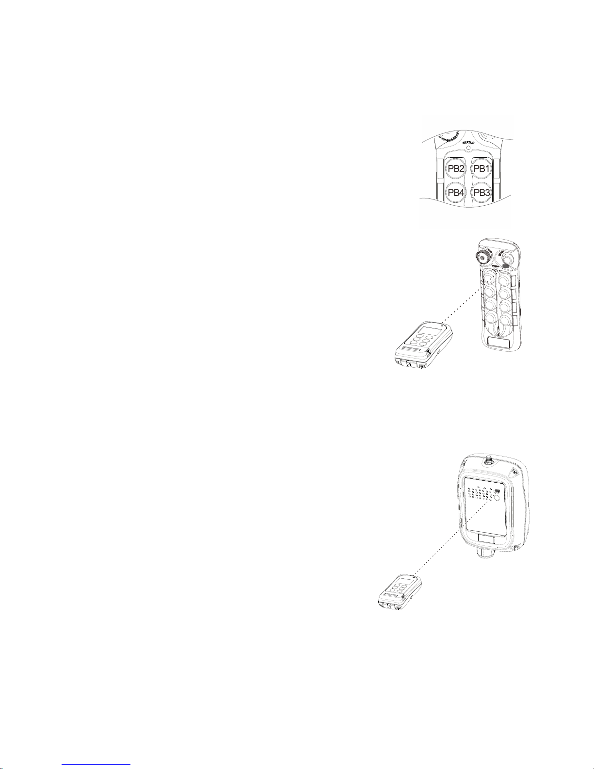
Page 44
8. Flex BASE Models
8.1 Program IR
8.1.1 Transmitter
1) Pressed down the STOP button (transmitter power off).
2) Press and hold PB1 and PB3 at the same time.
3) Reset the STOP button by rotating it clockwise or
counter-clockwise, it will pop up.
4) Release PB1 and PB3 at the same time. The
transmitter Status LED displays firmware version with
red, green and orange blinks.
5) Press READ button to transfer transmitter info into the
IR programmer. If the screen shows “READ OK”
the transfer is completed.
6) Browse through list of settings by pressing “↑” and
“↓” buttons (see section 8.2 and on).
7) Press WRITE button to transfer the new settings
into the transmitter (transmitter Status LED
constant orange). If the screen shows “WRITE
OK” the transfer is completed (transmitter Status
LED constant green for up to 2 seconds).
8) Exit Program IR by pressing the “BACK” button
until the cursor is shown next to “Program”.
9) Press “↑” and “↓” button to scroll through other
Flex BASE settings.
8.1.2 Receiver
1) Power on the receiver with MAIN relays
deactivated (standby mode).
2) Press READ button to transfer receiver info
into the IR programmer. If the screen shows
“READ OK” the transfer is completed.
3) Browse through list of settings by pressing “↑”
and “↓” buttons (see section 8.2 and on).
4) Press WRITE button to transfer the new
settings into the receiver (receiver Status LED
constant orange). If the screen shows “WRITE
OK” the transfer is completed (receiver Status
LED blinks green – standby mode).
5) Exit Program IR by pressing the “BACK” button
until the cursor is shown next to “Program”.
6) Press “↑” and “↓” button to scroll through other
Flex BASE settings.
Note: When performing infrared programming make sure the distance between the IR programmer and the
transmitter or receiver is within 10cm.
Page 46

Page 45
8.2 Program Serial Number (TX & RX)
1) Press “→” button to enter Serial Number setting.
2) Press “↑” and “↓” button to change serial number as a whole or…
3) Press “→” button to go to the 1st digit on the far left of the serial number.
4) Press “↑” and “↓” button to change numeric value.
5) Press “→” button to go to the next digit to the right and repeat step 4.
6) Press BACK button to go back to step 2 or 3.
7) Exit Program Serial Number by pressing the “BACK” button until the cursor
is shown next to “S/N:”.
8) Press “↑” and “↓” button to scroll through other Flex BASE settings.
8.3 Program System Type (TX & RX)
1) Press “→” button to enter System Type setting.
2) Press “↑” and “↓” button to change system type as a whole or…
3) Press “→” button to go to the digit on the far left.
4) Press “↑” and “↓” button to change numeric value.
5) Press “→” button to go to the next digit to the right and repeat step 4.
6) Press BACK button to go back to step 2 or 3.
7) Exit Program System Type by pressing the “BACK” button until the cursor
is shown next to “TYPE:”.
8) Press “↑” and “↓” button to scroll through other Flex BASE settings.
8.4 Program RS Function (TX & RX)
1) Press “→” button to enter RS Function setting.
2) Press “↑” and “↓” button to change RS Function type number.
3) Press “→” button and then “↑” and “↓” button to select “LOCK” for all Select
buttons interlocked and “UNLOCK” for all Select buttons non-interlocked.
4) Type 06 can further set PB7~PB10 Select buttons and PB11~PB12 Select
buttons “LOCK” or “UNLOCK”.
5) Exit Program RS Function by pressing the “BACK” button until the cursor
is shown next to “RS FUNC:”.
6) Press “↑” and “↓” button to scroll through other Flex BASE settings.
8.5 Program System Frequency Range (TX & RX)
1) Press “→” button to enter Frequency Range setting.
2) Press “↑” and “↓” button to change frequency range.
3) Exit Program System Frequency Range by pressing the “BACK” button
until the cursor is shown next to “FREQ:”.
4) Press “↑” and “↓” button to scroll through other Flex BASE settings.
Page 47

Page 46
8.6 Program System Channel (TX & RX)
1) Press “→” button to enter System Channel setting.
2) Press “↑” and “↓” button to change system channel as a whole or…
3) Press “→” button to go to the digit on the left.
4) Press “↑” and “↓” button to change numeric value.
5) Press “→” button to go to the next digit to the right and repeat step 4.
6) Press BACK button to go back to step 2 or 3.
7) Exit Program System Channel by pressing the “BACK” button until the
cursor is shown next to “CHANNEL”.
8) Press “↑” and “↓” button to scroll through other Flex BASE settings.
8.7 Program RF Power (TX)
1) Press “→” button to enter RF Power setting.
2) Press “↑” and “↓” button to change RF power (0.01mW ~ 10mW).
3) Press “→” button and then “↑” and “↓” button to enable or disable RF
power adjustment via transmitter dipswitch.
4) Exit Program RF Power by pressing the “BACK” button until the cursor is
shown next to “RFpower”.
5) Press “↑” and “↓” button to scroll through other Flex BASE settings.
8.8 Program Pushbutton Functions (TX)
1) Press “→” button to enter Pushbutton Function setting.
2) Press “↑” and “↓” button to change pushbutton function as a whole or…
3) Press “→” button to go to the digit on the left.
4) Press “↑” and “↓” button to change numeric value.
5) Press “→” button to go to the next digit to the right and repeat step 4.
6) Press BACK button to go back to step 2 or 3.
7) Exit Program Pushbutton Functions by pressing the “BACK” button until
the cursor is shown next to “PB FUNC”.
8) Press “↑” and “↓” button to scroll through other Flex BASE settings.
The transmitter pushbutton function table on Section 12 Part-C illustrates which numeric value
corresponds to which pushbutton function.
8.9 Program Transmitter Inactivity Timer (TX)
1) Press “→” button to enter Transmitting Timer setting.
2) Press “↑” and “↓” button to select “_M” for minutes/seconds or “ON” for
constant on.
3) When “ON” is selected, press “→” button and then “↑” and “↓” button to
select “+START” or “+ANY”.
4) When “_M” is selected, press “→” button to go to the digit on the
left and press “↑” and “↓” button to select value. Press “→” button again to
go to the next digit and press “↑” and “↓” button to select value .
5) Press “→” button again to select “M” for minutes or “S” for seconds. Press
“↑” and “↓” button to select.
6) Press “→” button again to select “+START” or “+ANY” selection. Press
“↑” and “↓” button to select.
7) Exit Program Transmitter Timer by pressing the “BACK” button until the
cursor is shown next to “TX TIMER”.
Page 48

Page 47
8) Press “↑” and “↓” button to scroll through other Flex BASE settings.
Transmitter inactivity timer is for setting receiver main relays cutoff time when the transmitter
is not in operation for a certain period of time. When set to 5 minutes (05M), the receiver
main relays are deactivated at 5.0 minutes after last transmitter operation.
Select “ON” means the receiver main relays are activated at all time unless the STOP button
is pressed down or receiver power turned off (inactivity timer disabled).
Select “+START” means after 5 minutes of transmitter inactivity you must press the green
START button to continue operation. Select “+ANY” means after 5 minutes of transmitter
inactivity press any pushbutton to continue operation.
8.10 Program Channel Scanning (RX)
1) Press “→” button to enter Channel Scanning setting.
2) Press “↑” and “↓” button to select number of channel to scan (01~12).
3) Exit Program Channel Scanning by pressing the “BACK” button until the
cursor is shown next to “CH SCAN”.
4) Press “↑” and “↓” button to scroll through other Flex BASE settings.
Note: Make sure the Channel dipswitch in receiver position 7 and 8 is set to
“11” in order for this to work (refer to manual section 4.2.2.11).
8.11 Program Function Relay 1 / K25 Relay (RX)
1) Press “→” button to enter Function Relay 1 setting.
2) Press “↑” and “↓” button to scroll and select.
3) Exit Program Function Relay 1 by pressing the “BACK” button until the
cursor is shown next to “FUNC RLY1”.
4) Press “↑” and “↓” button to scroll through other Flex BASE settings.
--- : START function only.
LV : Function relay closes when receiver voltage is low.
ID : Function relay works simultaneously with all motion commands.
NORMAL : START function + AUX with normal momentary output.
TOGGLE : START function + AUX with toggled/latching output.
TOG&E : START function + AUX with toggled/latching output. The relay opens when
STOP button is pressed down and transmitter power off.
EXT : FUNCTION relay works simultaneously with the receiver MAIN relays.
TDM A+B : FUNCTION relay closes when selector switch is rotated to the A+B position
and opens when rotate to A or B positions (tandem monitoring output).
HORN : FUNCTION relay closes for up to 3 seconds when Start command is initiated at
transmitter power on and then becomes normal momentary outputs thereafter.
RS : For RS system, the function relay works simultaneously with the Select pushbutton.
Page 49

Page 48
8.12 Program Function Relay 2 / K26 Relay (RX)
1) Press “→” button to enter Function Relay 2 setting.
2) Press “↑” and “↓” button to scroll and select.
3) Exit Program Function Relay 2 by pressing the “BACK” button until the
cursor is shown next to “FUNC RLY2”.
4) Press “↑” and “↓” button to scroll through other Flex BASE settings.
--- : START function only.
LV : Function relay closes when receiver voltage is low.
ID : Function relay works simultaneously with all motion commands.
NORMAL : START function + AUX with normal momentary output.
TOGGLE : START function + AUX with toggled/latching output.
TOG&E : START function + AUX with toggled/latching output. The relay opens when
STOP button is pressed down and transmitter power off.
EXT : FUNCTION relay works simultaneously with the receiver MAIN relays.
TDM A+B : FUNCTION relay closes when selector switch is rotated to the A+B position
and opens when rotate to A or B positions (tandem monitoring output).
HORN : FUNCTION relay closes for up to 3 seconds when Start command is initiated at
transmitter power on and then becomes normal momentary outputs thereafter.
RS : For RS system, the function relay works simultaneously with the Select pushbutton.
8.13 Program Function Relay 3 / K30 Relay (RX)
1) Press “→” button to enter Function Relay 3 setting.
2) Press “↑” and “↓” button to scroll and select.
3) Exit Program Function Relay 3 by pressing the “BACK” button until the
cursor is shown next to “FUNC RLY3”.
4) Press “↑” and “↓” button to scroll through other Flex BASE settings.
--- : START function only.
LV : Function relay closes when receiver voltage is low.
ID : Function relay works simultaneously with all motion commands.
NORMAL : START function + AUX with normal momentary output.
TOGGLE : START function + AUX with toggled/latching output.
TOG&E : START function + AUX with toggled/latching output. The relay opens when
STOP button is pressed down and transmitter power off.
EXT : FUNCTION relay works simultaneously with the receiver MAIN relays.
TDM A+B : FUNCTION relay closes when selector switch is rotated to the A+B position
and opens when rotate to A or B positions (tandem monitoring output).
HORN : FUNCTION relay closes for up to 3 seconds when Start command is initiated at
transmitter power on and then becomes normal momentary outputs thereafter.
RS : For RS system, the function relay works simultaneously with the Select pushbutton.
Page 50

Page 49
8.14 Program Brake Functions (RX)
1) Press “→” button to enter Brake function setting.
2) Press “↑” and “↓” button to scroll and select.
3) Exit Program Brake Functions by pressing the “BACK” button until
the cursor is shown next to “BRAKE”.
4) Press “↑” and “↓” button to scroll through other Flex BASE settings.
DEMAG 1 : When releasing pushbutton from 2
nd
speed up to 1st speed, the 1
st
speed
output relay will open for up to 1.0 second and then closes again.
DEMAG 2 : When pushbutton is pressed down to 2
nd
speed directly from 0 speed, the 1st
speed output relay will maintain closure for up to 0.4 second before 2
nd
speed
output relay closes. When pushbutton is released from 2nd speed up to 0
speed, the 1st speed output relay will maintain closure for up to 0.5 second
before going to 0 speed.
DEMAG 3 : When releasing pushbutton from 2
nd
speed up to 1st speed, both 1st and 2nd
speed output relays are opened. Release pushbutton to 0 speed and then
press down to 1
st
speed to reengage the 1st speed output relay.
P&H : When releasing pushbutton from 2
nd
speed up to 0 speed, the 1
st
speed
output relay will maintain closure for up to 0.1 second before going to 0 speed.
8.15 Program MRX Micro Receiver PB type (RX)
1) Press “→” button 2 times to enter PB Type setting.
2) Press “↑” and “↓” button to scroll and select. PB1~4 setting means the
receiver corresponds to PB1~PB4 on the transmitter. PB5~8 means the
receiver corresponds to PB5~PB8 on the transmitter. PB9~12 means the
receiver corresponds to PB9~PB12 on the transmitter. Inline means the
PB number is counted from top to bottom instead of right to left.
3) Exit Program Micro Receiver PB Type by pressing the “BACK” button
until the cursor is shown next to “MICRO RX”.
4) Press “↑” and “↓” button to scroll through other Flex BASE settings.
Page 51
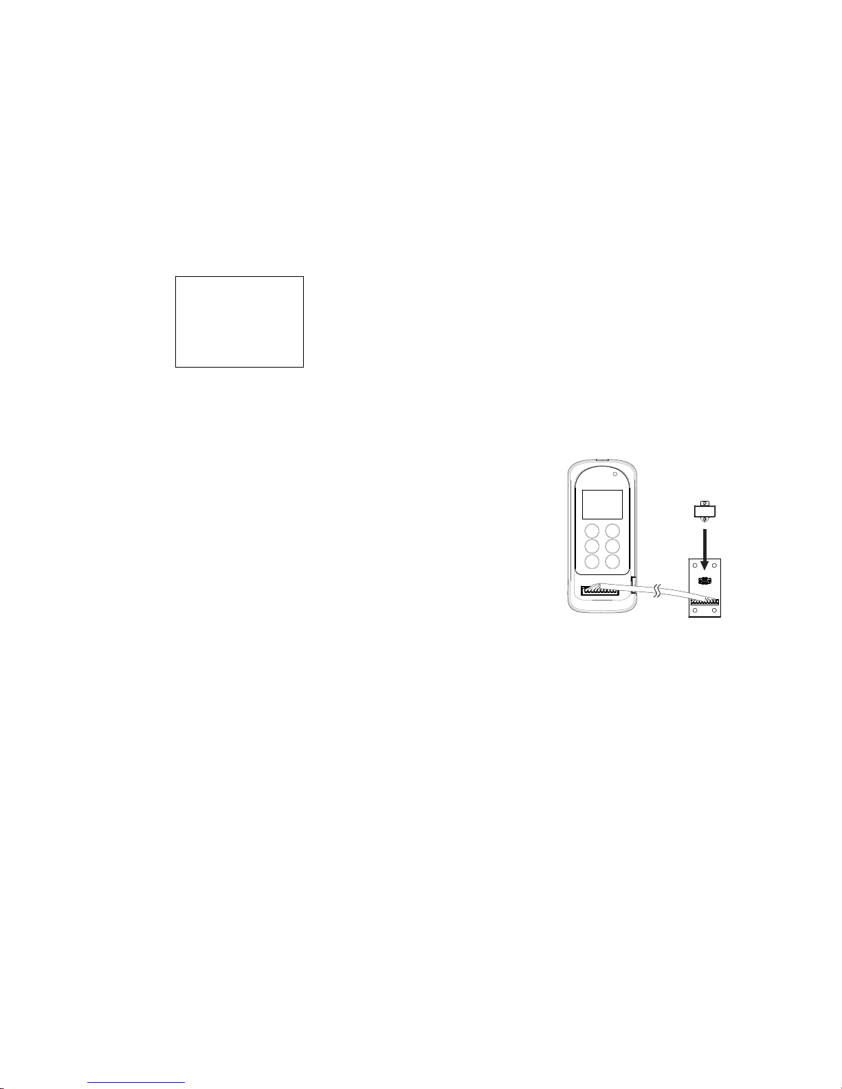
Page 50
9. Flex EP-H (Hydraulic) Models
9.1 Program I-Chip
When entering the Flex EP-H model the first selection shown on the screen is
“Program I-Chip” or “Program IR”. Use the “↑” and “↓” buttons to scroll
through various Flex EP-H settings or press “→” button to enter “Program IChip” or “Program IR”. Then press “↑” and “↓” button to select.
Program I-Chip:
1) Make sure the I-Chip is connected to the programmer.
2) Press READ button to store the I-Chip
information into the programmer. If the screen
shows “READ OK” the transfer is completed.
3) Press WRITE button to transfer the stored I-
Chip information into the I-Chip. If the screen
shows “WRITE OK” the transfer is completed.
4) Press “→” button to reformat the I-Chip, press
“→” button again to execute.
5) Exit I-Chip programming by pressing the “BACK”
button until the cursor is shown next to “Program”.
6) Press “↑” and “↓” button to scroll through other
Flex EP-H settings.
Program IR (infrared):
A. Program transmitter:
1) When programming the transmitter via IR, first turn off the transmitter
power and then rotate the power switch START position while both PB3
and PB4 are pressed down and then let go. At this time the STATUS
light will display transmitter firmware version.
2) Press “→” button to enter IR setting.
3) Press READ button to store the transmitter info into the programmer. If the
screen shows “READ OK” the transfer is completed.
4) Press WRITE button to transfer the stored info into the transmitter. If the
screen shows “WRITE OK” while transmitter STATUS light displays constant
orange (writing in progress) and then constant green for up to 2 seconds the
transfer is completed.
5) Exit Program IR by pressing the “BACK” button until the cursor is shown
next to “Program”.
6) Press “↑” and “↓” button to scroll through other Flex EP-H settings.
>PROGRAM
I-CHIP
FORMAT
Page 52
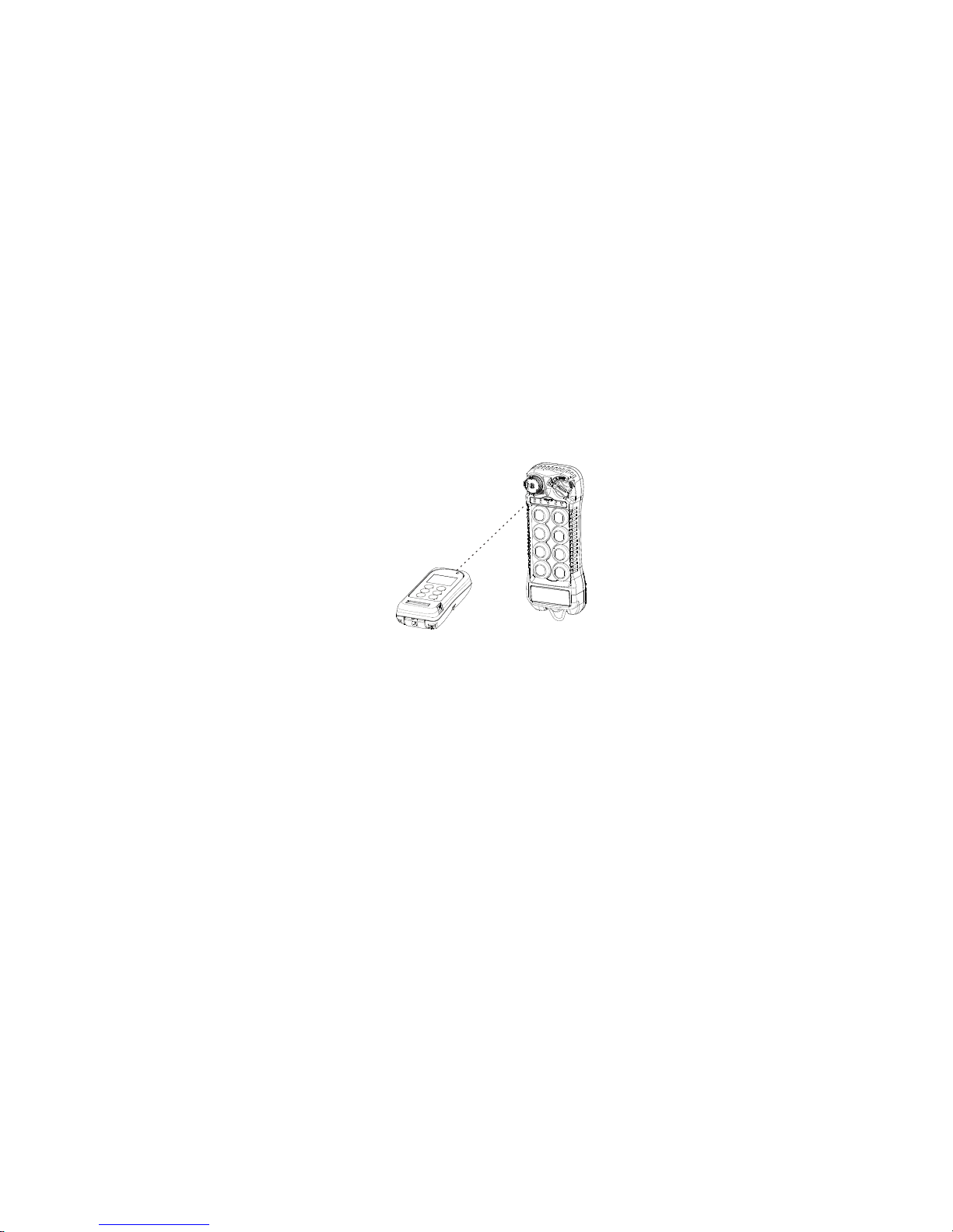
Page 51
B. Program receiver:
1) When programming the receiver the power must be turned on with receiver
MAIN relays deactivated.
2) Press “→” button to enter IR setting.
3) Press READ button to store the receiver info into the programmer. If the
screen shows “READ OK” the transfer is completed.
4) Press WRITE button to transfer the stored info into the receiver. If the screen
shows “WRITE OK” the transfer is completed. The receiver will restart
automatically after 2 seconds.
5) Exit Program IR by pressing the “BACK” button until the cursor is shown
next to “Program”.
6) Press “↑” and “↓” button to scroll through other Flex EP-H settings.
Note: When performing infrared programming make sure the distance between the
programmer and the transmitter or receiver is within 10cm.
9.2 Program Serial Number (TX & RX)
1) Make sure the I-Chip is connected to the programmer.
2) Press “→” button to enter Serial Number setting.
3) Press “↑” and “↓” button to change serial number as a whole or…
4) Press “→” button to go to the 1
st
digit on the far left of the serial number.
5) Press “↑” and “↓” button to change numeric value.
6) Press “→” button to go to the next digit to the right and repeat step 5.
7) Press BACK button to go back to step 3 or 4.
8) Exit Program Serial Number by pressing the “BACK” button until the cursor
is shown next to “S/N:”.
9) Press “↑” and “↓” button to scroll through other Flex EP-H settings.
9.3 Program System Type (TX & RX)
System Type is associated with functions such as tandem operation, random
access operation, multi-receiver operation, etc... Please do not alter the
factory settings unless authorized to do so.
Page 53

Page 52
9.4 Program System Frequency Range (TX & RX)
1) Make sure the I-Chip is connected to the programmer.
2) Press “→” button to enter System Frequency Range setting.
3) Press “↑” and “↓” button to change frequency range.
4) Exit Program System Frequency Range by pressing the “BACK” button
until the cursor is shown next to “FREQ:”.
5) Press “↑” and “↓” button to scroll through other Flex EP-H settings.
9.5 Program System Channel (TX & RX)
1) Make sure the I-Chip is connected to the programmer.
2) Press “→” button to enter System Channel setting.
3) Press “↑” and “↓” button to change system channel as a whole or…
4) Press “→” button to go to the digit on the left.
5) Press “↑” and “↓” button to change numeric value.
6) Press “→” button to go to the next digit to the right and repeat step 5.
7) Press BACK button to go back to step 3 or 4.
8) Exit Program System Channel by pressing the “BACK” button until the
cursor is shown next to “CHANNEL”.
9) Press “↑” and “↓” button to scroll through other Flex EP-H settings.
9.6 Program Transmitter Inactivity Timer (TX)
1) Make sure the I-Chip is connected to the programmer.
2) Press “→” button to enter Transmitting Timer setting.
3) Press “↑” and “↓” button to select “__M__S” or “ON”.
4) When “ON” is selected, press “→” button and then “↑” and “↓” button to
select “+START” or “+ANY”.
5) When “__M__S” is selected, press “→” button to go to the digit on the far
left and press “↑” and “↓” button to select value.
6) Press “→” button to go to the next digit to the right and repeat step 5.
7) When programming “__M__S” is completed, press “→” button to enter
“+START” or “+ANY” selection.
8) Press “↑” and “↓” button to select “+START” or “+ANY”.
9) Exit Program Transmitter Timer by pressing the “BACK” button until the
cursor is shown next to “TX TIMER”.
10) Press “↑” and “↓” button to scroll through other Flex EP-H settings.
Transmitter inactivity timer is for setting receiver main relays cutoff time when the transmitter
is not in operation for a certain period of time. When set to 5 minutes (05M), the receiver
main relays are deactivated at 5.0 minutes after last transmitter operation.
Select “ON” means the receiver main relays are activated at all time unless the STOP button
is pressed down, transmitter power turned off, or receiver power turned off (inactivity timer
disabled).
Select “+START” means after 5 minutes of transmitter inactivity you must rotate the power
keyswitch to START position to continue operation. Select “+ANY” means after 5 minutes of
transmitter inactivity press any pushbutton to continue operation.
Page 54

Page 53
9.7 Program RF Power (TX)
1) Make sure the I-Chip is connected to the programmer.
2) Press “→” button to enter RF Power setting.
3) Press “↑” and “↓” button to change RF power (0.1mW ~ 10mW).
4) Exit Program RF Power by pressing the “BACK” button until the cursor is
shown next to “RFpower”.
5) Press “↑” and “↓” button to scroll through other Flex EP-H settings.
9.8 Program Pushbutton Speed (TX)
1) Make sure the I-Chip is connected to the programmer.
2) Press “→” button to enter Pushbutton Speed setting.
3) Press “↑” and “↓” button to change percentage value (25, 50, 75, 100).
4) Exit Program Pushbutton Speed by pressing the “BACK” button until the
cursor is shown next to “PB SPEED”.
5) Press “↑” and “↓” button to scroll through other Flex EP-H settings.
9.9 Program Pushbutton Functions (TX)
1) Make sure the I-Chip is connected to the programmer.
2) Press “→” button to enter Pushbutton Function setting.
3) Press “↑” and “↓” button to change pushbutton function as a whole or…
4) Press “→” button to go to the digit on the left.
5) Press “↑” and “↓” button to change numeric value.
6) Press “→” button to go to the next digit to the right and repeat step 5.
7) Press BACK button to go back to step 3 or 4.
8) Exit Program Pushbutton Functions by pressing the “BACK” button until
the cursor is shown next to “PB FUNC”.
9) Press “↑” and “↓” button to scroll through other Flex EP-H settings.
Not yet available
9.10 Program Password (TX)
1) Make sure the I-Chip is connected to the programmer.
2) Press “→” button to enter Password setting.
3) Press “→” button to go to the 1st digit on the far left.
4) Press “↑” and “↓” button to change numeric value.
5) Press “→” button to go to the next digit to the right and repeat step 4.
6) Press BACK button to go back to step 3.
7) Exit Program Password by pressing the “BACK” button until the cursor is
shown next to “PASS WORD”.
8) Press “↑” and “↓” button to scroll through other Flex EP-H settings.
Only PB1 through PB4 are used when using the password function. Numeric
value “1” represents PB1, “2” represents PB2, “3” represents PB3 and “4”
represents PB4.
Setting “1111” → Password function disabled (manufacture preset)
Page 55

Page 54
9.11 Program Channel Scanning Function (RX)
1) Make sure the I-Chip is connected to the programmer.
2) Press “→” button to enter Channel Scanning setting.
3) Press “↑” and “↓” button to scroll and select between settings.
4) Exit Program Channel Scanning Function by pressing the “BACK” button until
the cursor is shown next to “CH SCAN”.
5) Press “↑” and “↓” button to scroll through other Flex EP-H settings.
Select “01” the receiver only scans the channel set on the receiver.
Select “02” the receiver scans the channel set on the receiver plus the next channel up (scans
channel N and channel N+1).
Select “03” the receiver scans the channel set on the receiver plus the next two channels
up (scans channel N, channel N+1 and channel N+2).
Select “ALL” the receiver scans all 62 channels.
9.12 Program MAIN Relay Function (RX)
1) Make sure the I-Chip is connected to the programmer.
2) Press “→” button to enter MAIN Relay setting.
3) Press “↑” and “↓” button to scroll and select between Test and Normal.
4) Exit Program MAIN Relay Function by pressing the “BACK” button until
the cursor is shown next to “MAIN RLY”.
5) Press “↑” and “↓” button to scroll through other Flex EP-H settings.
Select “NORMAL” for normal operation (receiver mains and all other outputs enabled).
Select “TEST” for system testing (receiver mains disabled and all other outputs enabled).
9.13 Program Function Relay 1 / K21 Relay (RX)
1) Make sure the I-Chip is connected to the programmer.
2) Press “→” button to enter Function Relay 1 setting.
3) Press “↑” and “↓” button to scroll and select.
4) Exit Program Function Relay 1 by pressing the “BACK” button until the
cursor is shown next to “FUNC RLY1”.
5) Press “↑” and “↓” button to scroll through other Flex EP-H settings.
LV : Function relay closes when receiver voltage is low.
ID : Function relay works simultaneously with all motion commands.
NORMAL : START function + AUX with normal momentary output.
TOGGLE : START function + AUX with toggled/latching output.
TOG&E : START function + AUX with toggled/latching output. The relay opens when
STOP button is pressed down and transmitter power off.
EXT : FUNCTION relay works simultaneously with the receiver MAIN relays.
S/P : FUNCTION relay closes when Start command is initiated and opens only when
transmitter power is turned off.
HORN : FUNCTION relay closes for up to 3 seconds when Start command is initiated at
transmitter power on and then becomes normal momentary outputs thereafter.
G SENSOR : FUNCTION relay closes when Zero-G sensor is triggered (receiver MAIN
relays deactivated) and opens when receiver MAIN relays are reactivated.
Page 56

Page 55
9.14 Program Function Relay 2 / K22 Relay (RX)
1) Make sure the I-Chip is connected to the programmer.
2) Press “→” button to enter Function Relay 1 setting.
3) Press “↑” and “↓” button to scroll and select.
4) Exit Program Function Relay 1 by pressing the “BACK” button until the
cursor is shown next to “FUNC RLY1”.
5) Press “↑” and “↓” button to scroll through other Flex EP-H settings.
LV : Function relay closes when receiver voltage is low.
ID : Function relay works simultaneously with all motion commands.
NORMAL : START function + AUX with normal momentary output.
TOGGLE : START function + AUX with toggled/latching output.
TOG&E : START function + AUX with toggled/latching output. The relay opens when
STOP button is pressed down and transmitter power off.
EXT : FUNCTION relay works simultaneously with the receiver MAIN relays.
S/P : FUNCTION relay closes when Start command is initiated and opens only when
transmitter power is turned off.
HORN : FUNCTION relay closes for up to 3 seconds when Start command is initiated at
transmitter power on and then becomes normal momentary outputs thereafter.
G SENSOR : FUNCTION relay closes when Zero-G sensor is triggered (receiver MAIN
relays deactivated) and opens when receiver MAIN relays are reactivated.
9.15 Program ID1 Outputs (RX)
Set ID1 output type when Function Relay 1 is set to “ID”.
1) Make sure the I-Chip is connected to the programmer.
2) Press “→” button to enter ID1 Output setting.
3) Press “→” button again then “↑” and “↓” button to scroll and select “Digital”,
“Current”, Voltage or “PWM”.
4) Press “BACK” button and then “↑” and “↓” button to select values for “Current”,
“Voltage”, and “PWM” settings.
5) Press “→” button to enter setting and “↑” and “↓” button to select numeric
value for the digit to the far left. Press “→” button to go to the next digit and
press “↑” and “↓” button to select.
6) Press “BACK” button to go back to step 5.
7) Exit Program ID1 Output by pressing the “BACK” button until the cursor is
shown next to “ID1 OUT”.
8) Press “↑” and “↓” button to scroll through other Flex EP-H settings.
Page 57

Page 56
9.16 Program ID2 Outputs (RX)
Set ID2 output type when Function Relay 2 is set to “ID”.
1) Make sure the I-Chip is connected to the programmer.
2) Press “→” button to enter ID2 Output setting.
3) Press “→” button again then “↑” and “↓” button to scroll and select “Digital”,
“Current”, Voltage or “PWM”.
4) Press “BACK” button and then “↑” and “↓” button to select values for “Current”,
“Voltage”, and “PWM” settings.
5) Press “→” button to enter setting and “↑” and “↓” button to select numeric
value for the digit to the far left. Press “→” button to go to the next digit and
press “↑” and “↓” button to select.
6) Press “BACK” button to go back to step 5.
7) Exit Program ID2 Output by pressing the “BACK” button until the cursor is
shown next to “ID2 OUT”.
8) Press “↑” and “↓” button to scroll through other Flex EP-H settings.
9.17 Program ID1 Ramp (RX)
1) Make sure the I-Chip is connected to the programmer.
2) Press “→” button to enter ID1 Ramp setting.
3) Press “↑” and “↓” button to scroll and select “ACC” for acceleration and
“DEC” for deceleration and press “→” button to enter.
4) Press “↑” and “↓” button to change value.
5) Press “BACK” button to go back to step 3.
6) Exit Program ID1 Ramp by pressing the “BACK” button until the cursor is
shown next to “ID1 RAMP”.
7) Press “↑” and “↓” button to scroll through other Flex EP-H settings.
9.18 Program ID2 Ramp (RX)
1) Make sure the I-Chip is connected to the programmer.
2) Press “→” button to enter ID2 Ramp setting.
3) Press “↑” and “↓” button to scroll and select “ACC” for acceleration and
“DEC” for deceleration and press “→” button to enter.
4) Press “↑” and “↓” button to change value.
5) Press “BACK” button to go back to step 3.
6) Exit Program ID2 Ramp by pressing the “BACK” button until the cursor is
shown next to “ID2 RAMP”.
7) Press “↑” and “↓” button to scroll through other Flex EP-H settings.
Page 58

Page 57
9.19 Program PB1 Output Relay (RX)
1) Make sure the I-Chip is connected to the programmer.
2) Press “→” button to enter PB1 Output Relay setting.
3) Press “→” button and then “↑” and “↓” button to select “LOCK” or “UNLOCK”.
4) Press “BACK” button to go back to step 3.
5) Press “↓” button and then “→” button select PB1 Output Relay function.
6) Press “↑” and “↓” button to scroll and select.
7) Exit Program PB1 Output Relay by pressing the “BACK” button until the
cursor is shown next to “PB1 RLY”.
8) Press “↑” and “↓” button to scroll through other Flex EP-H settings.
UNLOCK Settings (PB1 and PB2 output relays not interlocked):
Select “NORMAL” the output relay becomes momentary contact.
Select “NORMAL+S” the output relay becomes momentary contact. Must press the green
START button together to work.
Select receiver “TOGGLE” the output relay becomes toggled contact.
Select receiver “TOGGLE&E” the output relay becomes toggled contact affected by the Stop
command (output relay opens when Stop button is pressed).
Select “PITCH” PB1 button becomes the “Pitch” function in Pitch & Catch Operation.
Select “PITCH&E” PB1 button becomes the “Pitch” function in Pitch & Catch Operation. When
Pitch command is initiated the receiver mains are disconnected.
Select “STOP” PB1 button becomes an auxiliary Stop function. Press to disconnect the receiver
mains and press START button to reconnect the receiver mains.
LOCK Settings (PB1 and PB2 output relays interlocked):
Select “NORMAL” both output relays become interlocking momentary contacts.
Select receiver “TOG/TOG” both output relays become interlocking toggled contacts.
Select receiver “TOG/TOG&E” both output relays become interlocking toggled contacts affected
by the Stop command (output relay opens when Stop button is pressed).
Select “ON/OFF” both output relays become interlocking On and Off contacts.
Select “ON/OFF+S” both output relays become interlocking On and Off contacts. Must press
the green START button along with the On or Off button to work.
Select “ON/OFF&E” both output relays become interlocking On and Off contacts affected by the
Stop command (output relay opens when Stop button is pressed).
Select “MAGNET” the two output relays become interlocking Magnet ON and OFF contacts.
Page 59

Page 58
9.20 Program PB2 Output Relay (RX)
1) Make sure the I-Chip is connected to the programmer.
2) Press “→” button to enter PB2 Output Relay setting.
3) Press “→” button and then “↑” and “↓” button to select “LOCK” or “UNLOCK”.
4) Press “BACK” button to go back to step 3.
5) Press “↓” button and then “→” button select PB2 Output Relay function.
6) Press “↑” and “↓” button to scroll and select.
7) Exit Program PB2 Output Relay by pressing the “BACK” button until the
cursor is shown next to “PB2 RLY”.
8) Press “↑” and “↓” button to scroll through other Flex EP-H settings.
UNLOCK Settings (PB2 and PB1 output relays not interlocked):
Select “NORMAL” the output relay becomes momentary contact.
Select “NORMAL+S” the output relay becomes momentary contact. Must press the green
START button together to work.
Select receiver “TOGGLE” the output relay becomes toggled contact.
Select receiver “TOGGLE&E” the output relay becomes toggled contact affected by the Stop
command (output relay opens when Stop button is pressed).
Select “PITCH” PB2 button becomes the “Pitch” function in Pitch & Catch Operation.
Select “PITCH&E” PB2 button becomes the “Pitch” function in Pitch & Catch Operation. When
Pitch command is initiated the receiver mains are disconnected.
Select “STOP” PB2 button becomes an auxiliary Stop function. Press to disconnect the receiver
mains and press START button to reconnect the receiver mains.
LOCK Settings (PB2 and PB1 output relays interlocked):
Select “NORMAL” both output relays become interlocking momentary contacts.
Select receiver “TOG/TOG” both output relays become interlocking toggled contacts.
Select receiver “TOG/TOG&E” both output relays become interlocking toggled contacts affected
by the Stop command (output relay opens when Stop button is pressed).
Select “ON/OFF” both output relays become interlocking On and Off contacts.
Select “ON/OFF+S” both output relays become interlocking On and Off contacts. Must press
the green START button along with the On or Off button to work.
Select “ON/OFF&E” both output relays become interlocking On and Off contacts affected by the
Stop command (output relay opens when Stop button is pressed).
Select “MAGNET” the two output relays become interlocking Magnet ON and OFF contacts.
Page 60

Page 59
9.21 Program PB3 Output Relay (RX)
1) Make sure the I-Chip is connected to the programmer.
2) Press “→” button to enter PB3 Output Relay setting.
3) Press “→” button and then “↑” and “↓” button to select “LOCK” or “UNLOCK”.
4) Press “BACK” button to go back to step 3.
5) Press “↓” button and then “→” button select PB3 Output Relay function.
6) Press “↑” and “↓” button to scroll and select.
7) Exit Program PB3 Output Relay by pressing the “BACK” button until the
cursor is shown next to “PB3 RLY”.
8) Press “↑” and “↓” button to scroll through other Flex EP-H settings.
UNLOCK Settings (PB3 and PB4 output relays not interlocked):
Select “NORMAL” the output relay becomes momentary contact.
Select “NORMAL+S” the output relay becomes momentary contact. Must press the green
START button together to work.
Select receiver “TOGGLE” the output relay becomes toggled contact.
Select receiver “TOGGLE&E” the output relay becomes toggled contact affected by the Stop
command (output relay opens when Stop button is pressed).
Select “PITCH” PB3 button becomes the “Pitch” function in Pitch & Catch Operation.
Select “PITCH&E” PB3 button becomes the “Pitch” function in Pitch & Catch Operation. When
Pitch command is initiated the receiver mains are disconnected.
Select “STOP” PB3 button becomes an auxiliary Stop function. Press to disconnect the receiver
mains and press START button to reconnect the receiver mains.
LOCK Settings (PB3 and PB4 output relays interlocked):
Select “NORMAL” both output relays become interlocking momentary contacts.
Select receiver “TOG/TOG” both output relays become interlocking toggled contacts.
Select receiver “TOG/TOG&E” both output relays become interlocking toggled contacts affected
by the Stop command (output relay opens when Stop button is pressed).
Select “ON/OFF” both output relays become interlocking On and Off contacts.
Select “ON/OFF+S” both output relays become interlocking On and Off contacts. Must press
the green START button along with the On or Off button to work.
Select “ON/OFF&E” both output relays become interlocking On and Off contacts affected by the
Stop command (output relay opens when Stop button is pressed).
Select “MAGNET” the two output relays become interlocking Magnet ON and OFF contacts.
Page 61

Page 60
9.22 Program PB4 Output Relay (RX)
1) Make sure the I-Chip is connected to the programmer.
2) Press “→” button to enter PB4 Output Relay setting.
3) Press “→” button and then “↑” and “↓” button to select “LOCK” or “UNLOCK”.
4) Press “BACK” button to go back to step 3.
5) Press “↓” button and then “→” button select PB4 Output Relay function.
6) Press “↑” and “↓” button to scroll and select.
7) Exit Program PB4 Output Relay by pressing the “BACK” button until the
cursor is shown next to “PB4 RLY”.
8) Press “↑” and “↓” button to scroll through other Flex EP-H settings.
UNLOCK Settings (PB4 and PB3 output relays not interlocked):
Select “NORMAL” the output relay becomes momentary contact.
Select “NORMAL+S” the output relay becomes momentary contact. Must press the green
START button together to work.
Select receiver “TOGGLE” the output relay becomes toggled contact.
Select receiver “TOGGLE&E” the output relay becomes toggled contact affected by the Stop
command (output relay opens when Stop button is pressed).
Select “PITCH” PB4 button becomes the “Pitch” function in Pitch & Catch Operation.
Select “PITCH&E” PB4 button becomes the “Pitch” function in Pitch & Catch Operation. When
Pitch command is initiated the receiver mains are disconnected.
Select “STOP” PB4 button becomes an auxiliary Stop function. Press to disconnect the receiver
mains and press START button to reconnect the receiver mains.
LOCK Settings (PB4 and PB3 output relays interlocked):
Select “NORMAL” both output relays become interlocking momentary contacts.
Select receiver “TOG/TOG” both output relays become interlocking toggled contacts.
Select receiver “TOG/TOG&E” both output relays become interlocking toggled contacts affected
by the Stop command (output relay opens when Stop button is pressed).
Select “ON/OFF” both output relays become interlocking On and Off contacts.
Select “ON/OFF+S” both output relays become interlocking On and Off contacts. Must press
the green START button along with the On or Off button to work.
Select “ON/OFF&E” both output relays become interlocking On and Off contacts affected by the
Stop command (output relay opens when Stop button is pressed).
Select “MAGNET” the two output relays become interlocking Magnet ON and OFF contacts.
Page 62

Page 61
9.23 Program PB5 Output Relay (RX)
1) Make sure the I-Chip is connected to the programmer.
2) Press “→” button to enter PB5 Output Relay setting.
3) Press “→” button and then “↑” and “↓” button to select “LOCK” or “UNLOCK”.
4) Press “BACK” button to go back to step 3.
5) Press “↓” button and then “→” button select PB5 Output Relay function.
6) Press “↑” and “↓” button to scroll and select.
7) Exit Program PB5 Output Relay by pressing the “BACK” button until the
cursor is shown next to “PB5 RLY”.
8) Press “↑” and “↓” button to scroll through other Flex EP-H settings.
UNLOCK Settings (PB5 and PB6 output relays not interlocked):
Select “NORMAL” the output relay becomes momentary contact.
Select “NORMAL+S” the output relay becomes momentary contact. Must press the green
START button together to work.
Select receiver “TOGGLE” the output relay becomes toggled contact.
Select receiver “TOGGLE&E” the output relay becomes toggled contact affected by the Stop
command (output relay opens when Stop button is pressed).
Select “PITCH” PB5 button becomes the “Pitch” function in Pitch & Catch Operation.
Select “PITCH&E” PB5 button becomes the “Pitch” function in Pitch & Catch Operation. When
Pitch command is initiated the receiver mains are disconnected.
Select “STOP” PB5 button becomes an auxiliary Stop function. Press to disconnect the receiver
mains and press START button to reconnect the receiver mains.
LOCK Settings (PB5 and PB6 output relays interlocked):
Select “NORMAL” both output relays become interlocking momentary contacts.
Select receiver “TOG/TOG” both output relays become interlocking toggled contacts.
Select receiver “TOG/TOG&E” both output relays become interlocking toggled contacts affected
by the Stop command (output relay opens when Stop button is pressed).
Select “ON/OFF” both output relays become interlocking On and Off contacts.
Select “ON/OFF+S” both output relays become interlocking On and Off contacts. Must press
the green START button along with the On or Off button to work.
Select “ON/OFF&E” both output relays become interlocking On and Off contacts affected by the
Stop command (output relay opens when Stop button is pressed).
Select “MAGNET” the two output relays become interlocking Magnet ON and OFF contacts.
Page 63

Page 62
9.24 Program PB6 Output Relay (RX)
1) Make sure the I-Chip is connected to the programmer.
2) Press “→” button to enter PB6 Output Relay setting.
3) Press “→” button and then “↑” and “↓” button to select “LOCK” or “UNLOCK”.
4) Press “BACK” button to go back to step 3.
5) Press “↓” button and then “→” button select PB6 Output Relay function.
6) Press “↑” and “↓” button to scroll and select.
7) Exit Program PB6 Output Relay by pressing the “BACK” button until the
cursor is shown next to “PB6 RLY”.
8) Press “↑” and “↓” button to scroll through other Flex EP-H settings.
UNLOCK Settings (PB6 and PB5 output relays not interlocked):
Select “NORMAL” the output relay becomes momentary contact.
Select “NORMAL+S” the output relay becomes momentary contact. Must press the green
START button together to work.
Select receiver “TOGGLE” the output relay becomes toggled contact.
Select receiver “TOGGLE&E” the output relay becomes toggled contact affected by the Stop
command (output relay opens when Stop button is pressed).
Select “PITCH” PB6 button becomes the “Pitch” function in Pitch & Catch Operation.
Select “PITCH&E” PB6 button becomes the “Pitch” function in Pitch & Catch Operation. When
Pitch command is initiated the receiver mains are disconnected.
Select “STOP” PB6 button becomes an auxiliary Stop function. Press to disconnect the receiver
mains and press START button to reconnect the receiver mains.
LOCK Settings (PB6 and PB5 output relays interlocked):
Select “NORMAL” both output relays become interlocking momentary contacts.
Select receiver “TOG/TOG” both output relays become interlocking toggled contacts.
Select receiver “TOG/TOG&E” both output relays become interlocking toggled contacts affected
by the Stop command (output relay opens when Stop button is pressed).
Select “ON/OFF” both output relays become interlocking On and Off contacts.
Select “ON/OFF+S” both output relays become interlocking On and Off contacts. Must press
the green START button along with the On or Off button to work.
Select “ON/OFF&E” both output relays become interlocking On and Off contacts affected by the
Stop command (output relay opens when Stop button is pressed).
Select “MAGNET” the two output relays become interlocking Magnet ON and OFF contacts.
Page 64

Page 63
9.25 Program PB7 Output Relay (RX)
1) Make sure the I-Chip is connected to the programmer.
2) Press “→” button to enter PB7 Output Relay setting.
3) Press “→” button and then “↑” and “↓” button to select “LOCK” or “UNLOCK”.
4) Press “BACK” button to go back to step 3.
5) Press “↓” button and then “→” button select PB7 Output Relay function.
6) Press “↑” and “↓” button to scroll and select.
7) Exit Program PB7 Output Relay by pressing the “BACK” button until the
cursor is shown next to “PB7 RLY”.
8) Press “↑” and “↓” button to scroll through other Flex EP-H settings.
UNLOCK Settings (PB7 and PB8 output relays not interlocked):
Select “NORMAL” the output relay becomes momentary contact.
Select “NORMAL+S” the output relay becomes momentary contact. Must press the green
START button together to work.
Select receiver “TOGGLE” the output relay becomes toggled contact.
Select receiver “TOGGLE&E” the output relay becomes toggled contact affected by the Stop
command (output relay opens when Stop button is pressed).
Select “PITCH” PB7 button becomes the “Pitch” function in Pitch & Catch Operation.
Select “PITCH&E” PB7 button becomes the “Pitch” function in Pitch & Catch Operation. When
Pitch command is initiated the receiver mains are disconnected.
Select “STOP” PB7 button becomes an auxiliary Stop function. Press to disconnect the receiver
mains and press START button to reconnect the receiver mains.
LOCK Settings (PB7 and PB8 output relays interlocked):
Select “NORMAL” both output relays become interlocking momentary contacts.
Select receiver “TOG/TOG” both output relays become interlocking toggled contacts.
Select receiver “TOG/TOG&E” both output relays become interlocking toggled contacts affected
by the Stop command (output relay opens when Stop button is pressed).
Select “ON/OFF” both output relays become interlocking On and Off contacts.
Select “ON/OFF+S” both output relays become interlocking On and Off contacts. Must press
the green START button along with the On or Off button to work.
Select “ON/OFF&E” both output relays become interlocking On and Off contacts affected by the
Stop command (output relay opens when Stop button is pressed).
Select “MAGNET” the two output relays become interlocking Magnet ON and OFF contacts.
Page 65

Page 64
9.26 Program PB8 Output Relay (RX)
1) Make sure the I-Chip is connected to the programmer.
2) Press “→” button to enter PB8 Output Relay setting.
3) Press “→” button and then “↑” and “↓” button to select “LOCK” or “UNLOCK”.
4) Press “BACK” button to go back to step 3.
5) Press “↓” button and then “→” button select PB8 Output Relay function.
6) Press “↑” and “↓” button to scroll and select.
7) Exit Program PB8 Output Relay by pressing the “BACK” button until the
cursor is shown next to “PB8 RLY”.
8) Press “↑” and “↓” button to scroll through other Flex EP-H settings.
UNLOCK Settings (PB8 and PB7 output relays not interlocked):
Select “NORMAL” the output relay becomes momentary contact.
Select “NORMAL+S” the output relay becomes momentary contact. Must press the green
START button together to work.
Select receiver “TOGGLE” the output relay becomes toggled contact.
Select receiver “TOGGLE&E” the output relay becomes toggled contact affected by the Stop
command (output relay opens when Stop button is pressed).
Select “PITCH” PB8 button becomes the “Pitch” function in Pitch & Catch Operation.
Select “PITCH&E” PB8 button becomes the “Pitch” function in Pitch & Catch Operation. When
Pitch command is initiated the receiver mains are disconnected.
Select “STOP” PB8 button becomes an auxiliary Stop function. Press to disconnect the receiver
mains and press START button to reconnect the receiver mains.
LOCK Settings (PB8 and PB7 output relays interlocked):
Select “NORMAL” both output relays become interlocking momentary contacts.
Select receiver “TOG/TOG” both output relays become interlocking toggled contacts.
Select receiver “TOG/TOG&E” both output relays become interlocking toggled contacts affected
by the Stop command (output relay opens when Stop button is pressed).
Select “ON/OFF” both output relays become interlocking On and Off contacts.
Select “ON/OFF+S” both output relays become interlocking On and Off contacts. Must press
the green START button along with the On or Off button to work.
Select “ON/OFF&E” both output relays become interlocking On and Off contacts affected by the
Stop command (output relay opens when Stop button is pressed).
Select “MAGNET” the two output relays become interlocking Magnet ON and OFF contacts.
Page 66

Page 65
9.27 Program PB9 Output Relay (RX)
1) Make sure the I-Chip is connected to the programmer.
2) Press “→” button to enter PB9 Output Relay setting.
3) Press “→” button and then “↑” and “↓” button to select “LOCK” or “UNLOCK”.
4) Press “BACK” button to go back to step 3.
5) Press “↓” button and then “→” button select PB9 Output Relay function.
6) Press “↑” and “↓” button to scroll and select.
7) Exit Program PB9 Output Relay by pressing the “BACK” button until the
cursor is shown next to “PB9 RLY”.
8) Press “↑” and “↓” button to scroll through other Flex EP-H settings.
UNLOCK Settings (PB9 and PB10 output relays not interlocked):
Select “NORMAL” the output relay becomes momentary contact.
Select “NORMAL+S” the output relay becomes momentary contact. Must press the green
START button together to work.
Select receiver “TOGGLE” the output relay becomes toggled contact.
Select receiver “TOGGLE&E” the output relay becomes toggled contact affected by the Stop
command (output relay opens when Stop button is pressed).
Select “PITCH” PB9 button becomes the “Pitch” function in Pitch & Catch Operation.
Select “PITCH&E” PB9 button becomes the “Pitch” function in Pitch & Catch Operation. When
Pitch command is initiated the receiver mains are disconnected.
Select “STOP” PB9 button becomes an auxiliary Stop function. Press to disconnect the receiver
mains and press START button to reconnect the receiver mains.
LOCK Settings (PB9 and PB10 output relays interlocked):
Select “NORMAL” both output relays become interlocking momentary contacts.
Select receiver “TOG/TOG” both output relays become interlocking toggled contacts.
Select receiver “TOG/TOG&E” both output relays become interlocking toggled contacts affected
by the Stop command (output relay opens when Stop button is pressed).
Select “ON/OFF” both output relays become interlocking On and Off contacts.
Select “ON/OFF+S” both output relays become interlocking On and Off contacts. Must press
the green START button along with the On or Off button to work.
Select “ON/OFF&E” both output relays become interlocking On and Off contacts affected by the
Stop command (output relay opens when Stop button is pressed).
Select “MAGNET” the two output relays become interlocking Magnet ON and OFF contacts.
Page 67

Page 66
9.28 Program PB10 Output Relay (RX)
1) Make sure the I-Chip is connected to the programmer.
2) Press “→” button to enter PB10 Output Relay setting.
3) Press “→” button and then “↑” and “↓” button to select “LOCK” or “UNLOCK”.
4) Press “BACK” button to go back to step 3.
5) Press “↓” button and then “→” button select PB10 Output Relay function.
6) Press “↑” and “↓” button to scroll and select.
7) Exit Program PB10 Output Relay by pressing the “BACK” button until the
cursor is shown next to “PB10 RLY”.
8) Press “↑” and “↓” button to scroll through other Flex EP-H settings.
UNLOCK Settings (PB10 and PB9 output relays not interlocked):
Select “NORMAL” the output relay becomes momentary contact.
Select “NORMAL+S” the output relay becomes momentary contact. Must press the green
START button together to work.
Select receiver “TOGGLE” the output relay becomes toggled contact.
Select receiver “TOGGLE&E” the output relay becomes toggled contact affected by the Stop
command (output relay opens when Stop button is pressed).
Select “PITCH” PB10 button becomes the “Pitch” function in Pitch & Catch Operation.
Select “PITCH&E” PB10 button becomes the “Pitch” function in Pitch & Catch Operation. When
Pitch command is initiated the receiver mains are disconnected.
Select “STOP” PB10 button becomes an auxiliary Stop function. Press to disconnect the receiver
mains and press START button to reconnect the receiver mains.
LOCK Settings (PB10 and PB9 output relays interlocked):
Select “NORMAL” both output relays become interlocking momentary contacts.
Select receiver “TOG/TOG” both output relays become interlocking toggled contacts.
Select receiver “TOG/TOG&E” both output relays become interlocking toggled contacts affected
by the Stop command (output relay opens when Stop button is pressed).
Select “ON/OFF” both output relays become interlocking On and Off contacts.
Select “ON/OFF+S” both output relays become interlocking On and Off contacts. Must press
the green START button along with the On or Off button to work.
Select “ON/OFF&E” both output relays become interlocking On and Off contacts affected by the
Stop command (output relay opens when Stop button is pressed).
Select “MAGNET” the two output relays become interlocking Magnet ON and OFF contacts.
Page 68

Page 67
9.29 Program PB11 Output Relay (RX)
1) Make sure the I-Chip is connected to the programmer.
2) Press “→” button to enter PB11 Output Relay setting.
3) Press “→” button and then “↑” and “↓” button to select “LOCK” or “UNLOCK”.
4) Press “BACK” button to go back to step 3.
5) Press “↓” button and then “→” button select PB11 Output Relay function.
6) Press “↑” and “↓” button to scroll and select.
7) Exit Program PB11 Output Relay by pressing the “BACK” button until the
cursor is shown next to “PB11 RLY”.
8) Press “↑” and “↓” button to scroll through other Flex EP-H settings.
UNLOCK Settings (PB11 and PB12 output relays not interlocked):
Select “NORMAL” the output relay becomes momentary contact.
Select “NORMAL+S” the output relay becomes momentary contact. Must press the green
START button together to work.
Select receiver “TOGGLE” the output relay becomes toggled contact.
Select receiver “TOGGLE&E” the output relay becomes toggled contact affected by the Stop
command (output relay opens when Stop button is pressed).
Select “PITCH” PB11 button becomes the “Pitch” function in Pitch & Catch Operation.
Select “PITCH&E” PB11 button becomes the “Pitch” function in Pitch & Catch Operation. When
Pitch command is initiated the receiver mains are disconnected.
Select “STOP” PB11 button becomes an auxiliary Stop function. Press to disconnect the receiver
mains and press START button to reconnect the receiver mains.
LOCK Settings (PB11 and PB12 output relays interlocked):
Select “NORMAL” both output relays become interlocking momentary contacts.
Select receiver “TOG/TOG” both output relays become interlocking toggled contacts.
Select receiver “TOG/TOG&E” both output relays become interlocking toggled contacts affected
by the Stop command (output relay opens when Stop button is pressed).
Select “ON/OFF” both output relays become interlocking On and Off contacts.
Select “ON/OFF+S” both output relays become interlocking On and Off contacts. Must press
the green START button along with the On or Off button to work.
Select “ON/OFF&E” both output relays become interlocking On and Off contacts affected by the
Stop command (output relay opens when Stop button is pressed).
Select “MAGNET” the two output relays become interlocking Magnet ON and OFF contacts.
Page 69

Page 68
9.30 Program PB12 Output Relay (RX)
1) Make sure the I-Chip is connected to the programmer.
2) Press “→” button to enter PB12 Output Relay setting.
3) Press “→” button and then “↑” and “↓” button to select “LOCK” or “UNLOCK”.
4) Press “BACK” button to go back to step 3.
5) Press “↓” button and then “→” button select PB12 Output Relay function.
6) Press “↑” and “↓” button to scroll and select.
7) Exit Program PB12 Output Relay by pressing the “BACK” button until the
cursor is shown next to “PB12 RLY”.
8) Press “↑” and “↓” button to scroll through other Flex EP-H settings.
UNLOCK Settings (PB12 and PB11 output relays not interlocked):
Select “NORMAL” the output relay becomes momentary contact.
Select “NORMAL+S” the output relay becomes momentary contact. Must press the green
START button together to work.
Select receiver “TOGGLE” the output relay becomes toggled contact.
Select receiver “TOGGLE&E” the output relay becomes toggled contact affected by the Stop
command (output relay opens when Stop button is pressed).
Select “PITCH” PB12 button becomes the “Pitch” function in Pitch & Catch Operation.
Select “PITCH&E” PB12 button becomes the “Pitch” function in Pitch & Catch Operation. When
Pitch command is initiated the receiver mains are disconnected.
Select “STOP” PB12 button becomes an auxiliary Stop function. Press to disconnect the receiver
mains and press START button to reconnect the receiver mains.
LOCK Settings (PB12 and PB11 output relays interlocked):
Select “NORMAL” both output relays become interlocking momentary contacts.
Select receiver “TOG/TOG” both output relays become interlocking toggled contacts.
Select receiver “TOG/TOG&E” both output relays become interlocking toggled contacts affected
by the Stop command (output relay opens when Stop button is pressed).
Select “ON/OFF” both output relays become interlocking On and Off contacts.
Select “ON/OFF+S” both output relays become interlocking On and Off contacts. Must press
the green START button along with the On or Off button to work.
Select “ON/OFF&E” both output relays become interlocking On and Off contacts affected by the
Stop command (output relay opens when Stop button is pressed).
Select “MAGNET” the two output relays become interlocking Magnet ON and OFF contacts.
Page 70

Page 69
9.31 Program PB1 Outputs (RX)
1) Make sure the I-Chip is connected to the programmer.
2) Press “→” button to enter PB1 Output setting.
3) Press “→” button again then “↑” and “↓” button to scroll and select “Digital”,
“Current”, Voltage or “PWM”.
4) Press “BACK” button and then “↑” and “↓” button to select values for “Current”,
“Voltage”, and “PWM” settings.
5) Press “→” button to enter setting and “↑” and “↓” button to select numeric
value for the digit to the far left. Press “→” button to go to the next digit and
press “↑” and “↓” button to select.
6) Press “BACK” button to go back to step 5.
7) Exit Program PB1 Output by pressing the “BACK” button until the cursor is
shown next to “PB1 OUT”.
8) Press “↑” and “↓” button to scroll through other Flex EP-H settings.
8.32 Program PB2 Outputs (RX)
1) Make sure the I-Chip is connected to the programmer.
2) Press “→” button to enter PB2 Output setting.
3) Press “→” button again then “↑” and “↓” button to scroll and select “Digital”,
“Current”, Voltage or “PWM”.
4) Press “BACK” button and then “↑” and “↓” button to select values for “Current”,
“Voltage”, and “PWM” settings.
5) Press “→” button to enter setting and “↑” and “↓” button to select numeric
value for the digit to the far left. Press “→” button to go to the next digit and
press “↑” and “↓” button to select.
6) Press “BACK” button to go back to step 5.
7) Exit Program PB2 Output by pressing the “BACK” button until the cursor is
shown next to “PB2 OUT”.
8) Press “↑” and “↓” button to scroll through other Flex EP-H settings.
8.33 Program PB3 Outputs (RX)
1) Make sure the I-Chip is connected to the programmer.
2) Press “→” button to enter PB3 Output setting.
3) Press “→” button again then “↑” and “↓” button to scroll and select “Digital”,
“Current”, Voltage or “PWM”.
4) Press “BACK” button and then “↑” and “↓” button to select values for “Current”,
“Voltage”, and “PWM” settings.
5) Press “→” button to enter setting and “↑” and “↓” button to select numeric
value for the digit to the far left. Press “→” button to go to the next digit and
press “↑” and “↓” button to select.
6) Press “BACK” button to go back to step 5.
7) Exit Program PB3 Output by pressing the “BACK” button until the cursor is
shown next to “PB3 OUT”.
8) Press “↑” and “↓” button to scroll through other Flex EP-H settings.
Page 71

Page 70
9.34 Program PB4 Outputs (RX)
1) Make sure the I-Chip is connected to the programmer.
2) Press “→” button to enter PB4 Output setting.
3) Press “→” button again then “↑” and “↓” button to scroll and select “Digital”,
“Current”, Voltage or “PWM”.
4) Press “BACK” button and then “↑” and “↓” button to select values for “Current”,
“Voltage”, and “PWM” settings.
5) Press “→” button to enter setting and “↑” and “↓” button to select numeric
value for the digit to the far left. Press “→” button to go to the next digit and
press “↑” and “↓” button to select.
6) Press “BACK” button to go back to step 5.
7) Exit Program PB4 Output by pressing the “BACK” button until the cursor is
shown next to “PB4 OUT”.
8) Press “↑” and “↓” button to scroll through other Flex EP-H settings.
9.35 Program PB5 Outputs (RX)
1) Make sure the I-Chip is connected to the programmer.
2) Press “→” button to enter PB5 Output setting.
3) Press “→” button again then “↑” and “↓” button to scroll and select “Digital”,
“Current”, Voltage or “PWM”.
4) Press “BACK” button and then “↑” and “↓” button to select values for “Current”,
“Voltage”, and “PWM” settings.
5) Press “→” button to enter setting and “↑” and “↓” button to select numeric
value for the digit to the far left. Press “→” button to go to the next digit and
press “↑” and “↓” button to select.
6) Press “BACK” button to go back to step 5.
7) Exit Program PB5 Output by pressing the “BACK” button until the cursor is
shown next to “PB5 OUT”.
8) Press “↑” and “↓” button to scroll through other Flex EP-H settings.
9.36 Program PB6 Outputs (RX)
1) Make sure the I-Chip is connected to the programmer.
2) Press “→” button to enter PB6 Output setting.
3) Press “→” button again then “↑” and “↓” button to scroll and select “Digital”,
“Current”, Voltage or “PWM”.
4) Press “BACK” button and then “↑” and “↓” button to select values for “Current”,
“Voltage”, and “PWM” settings.
5) Press “→” button to enter setting and “↑” and “↓” button to select numeric
value for the digit to the far left. Press “→” button to go to the next digit and
press “↑” and “↓” button to select.
6) Press “BACK” button to go back to step 5.
7) Exit Program PB6 Output by pressing the “BACK” button until the cursor is
shown next to “PB6 OUT”.
8) Press “↑” and “↓” button to scroll through other Flex EP-H settings.
Page 72

Page 71
9.37 Program PB7 Outputs (RX)
1) Make sure the I-Chip is connected to the programmer.
2) Press “→” button to enter PB7 Output setting.
3) Press “→” button again then “↑” and “↓” button to scroll and select “Digital”,
“Current”, Voltage or “PWM”.
4) Press “BACK” button and then “↑” and “↓” button to select values for “Current”,
“Voltage”, and “PWM” settings.
5) Press “→” button to enter setting and “↑” and “↓” button to select numeric
value for the digit to the far left. Press “→” button to go to the next digit and
press “↑” and “↓” button to select.
6) Press “BACK” button to go back to step 5.
7) Exit Program PB7 Output by pressing the “BACK” button until the cursor is
shown next to “PB7 OUT”.
8) Press “↑” and “↓” button to scroll through other Flex EP-H settings.
9.38 Program PB8 Outputs (RX)
1) Make sure the I-Chip is connected to the programmer.
2) Press “→” button to enter PB8 Output setting.
3) Press “→” button again then “↑” and “↓” button to scroll and select “Digital”,
“Current”, Voltage or “PWM”.
4) Press “BACK” button and then “↑” and “↓” button to select values for “Current”,
“Voltage”, and “PWM” settings.
5) Press “→” button to enter setting and “↑” and “↓” button to select numeric
value for the digit to the far left. Press “→” button to go to the next digit and
press “↑” and “↓” button to select.
6) Press “BACK” button to go back to step 5.
7) Exit Program PB8 Output by pressing the “BACK” button until the cursor is
shown next to “PB8 OUT”.
8) Press “↑” and “↓” button to scroll through other Flex EP-H settings.
9.39 Program PB9 Outputs (RX)
1) Make sure the I-Chip is connected to the programmer.
2) Press “→” button to enter PB9 Output setting.
3) Press “→” button again then “↑” and “↓” button to scroll and select “Digital”,
“Current”, Voltage or “PWM”.
4) Press “BACK” button and then “↑” and “↓” button to select values for “Current”,
“Voltage”, and “PWM” settings.
5) Press “→” button to enter setting and “↑” and “↓” button to select numeric
value for the digit to the far left. Press “→” button to go to the next digit and
press “↑” and “↓” button to select.
6) Press “BACK” button to go back to step 5.
7) Exit Program PB9 Output by pressing the “BACK” button until the cursor is
shown next to “PB9 OUT”.
8) Press “↑” and “↓” button to scroll through other Flex EP-H settings.
Page 73

Page 72
9.40 Program PB10 Outputs (RX)
1) Make sure the I-Chip is connected to the programmer.
2) Press “→” button to enter PB10 Output setting.
3) Press “→” button again then “↑” and “↓” button to scroll and select “Digital”,
“Current”, Voltage or “PWM”.
4) Press “BACK” button and then “↑” and “↓” button to select values for “Current”,
“Voltage”, and “PWM” settings.
5) Press “→” button to enter setting and “↑” and “↓” button to select numeric
value for the digit to the far left. Press “→” button to go to the next digit and
press “↑” and “↓” button to select.
6) Press “BACK” button to go back to step 5.
7) Exit Program PB10 Output by pressing the “BACK” button until the cursor
is shown next to “PB10 OUT”.
8) Press “↑” and “↓” button to scroll through other Flex EP-H settings.
9.41 Program PB11 Outputs (RX)
1) Make sure the I-Chip is connected to the programmer.
2) Press “→” button to enter PB11 Output setting.
3) Press “→” button again then “↑” and “↓” button to scroll and select “Digital”,
“Current”, Voltage or “PWM”.
4) Press “BACK” button and then “↑” and “↓” button to select values for “Current”,
“Voltage”, and “PWM” settings.
5) Press “→” button to enter setting and “↑” and “↓” button to select numeric
value for the digit to the far left. Press “→” button to go to the next digit and
press “↑” and “↓” button to select.
6) Press “BACK” button to go back to step 5.
7) Exit Program PB11 Output by pressing the “BACK” button until the cursor
is shown next to “PB11 OUT”.
8) Press “↑” and “↓” button to scroll through other Flex EP-H settings.
9.42 Program PB12 Outputs (RX)
1) Make sure the I-Chip is connected to the programmer.
2) Press “→” button to enter PB12 Output setting.
3) Press “→” button again then “↑” and “↓” button to scroll and select “Digital”,
“Current”, Voltage or “PWM”.
4) Press “BACK” button and then “↑” and “↓” button to select values for “Current”,
“Voltage”, and “PWM” settings.
5) Press “→” button to enter setting and “↑” and “↓” button to select numeric
value for the digit to the far left. Press “→” button to go to the next digit and
press “↑” and “↓” button to select.
6) Press “BACK” button to go back to step 5.
7) Exit Program PB12 Output by pressing the “BACK” button until the cursor
is shown next to “PB12 OUT”.
8) Press “↑” and “↓” button to scroll through other Flex EP-H settings.
Page 74

Page 73
9.43 Program PB1 Ramp (RX)
1) Make sure the I-Chip is connected to the programmer.
2) Press “→” button to enter PB1 Ramp setting.
3) Press “↑” and “↓” button to scroll and select “ACC” for acceleration and
“DEC” for deceleration and press “→” button to enter.
4) Press “↑” and “↓” button to change value.
5) Press “BACK” button to go back to step 3.
6) Exit Program PB1 Ramp by pressing the “BACK” button until the cursor is
shown next to “PB1 RAMP”.
7) Press “↑” and “↓” button to scroll through other Flex EP-H settings.
9.44 Program PB2 Ramp (RX)
1) Make sure the I-Chip is connected to the programmer.
2) Press “→” button to enter PB2 Ramp setting.
3) Press “↑” and “↓” button to scroll and select “ACC” for acceleration and
“DEC” for deceleration and press “→” button to enter.
4) Press “↑” and “↓” button to change value.
5) Press “BACK” button to go back to step 3.
6) Exit Program PB2 Ramp by pressing the “BACK” button until the cursor is
shown next to “PB2 RAMP”.
7) Press “↑” and “↓” button to scroll through other Flex EP-H settings.
9.45 Program PB3 Ramp (RX)
1) Make sure the I-Chip is connected to the programmer.
2) Press “→” button to enter PB3 Ramp setting.
3) Press “↑” and “↓” button to scroll and select “ACC” for acceleration and
“DEC” for deceleration and press “→” button to enter.
4) Press “↑” and “↓” button to change value.
5) Press “BACK” button to go back to step 3.
6) Exit Program PB3 Ramp by pressing the “BACK” button until the cursor is
shown next to “PB3 RAMP”.
7) Press “↑” and “↓” button to scroll through other Flex EP-H settings.
9.46 Program PB4 Ramp (RX)
1) Make sure the I-Chip is connected to the programmer.
2) Press “→” button to enter PB4 Ramp setting.
3) Press “↑” and “↓” button to scroll and select “ACC” for acceleration and
“DEC” for deceleration and press “→” button to enter.
4) Press “↑” and “↓” button to change value.
5) Press “BACK” button to go back to step 3.
6) Exit Program PB4 Ramp by pressing the “BACK” button until the cursor is
shown next to “PB4 RAMP”.
7) Press “↑” and “↓” button to scroll through other Flex EP-H settings.
Page 75

Page 74
9.47 Program PB5 Ramp (RX)
1) Make sure the I-Chip is connected to the programmer.
2) Press “→” button to enter PB5 Ramp setting.
3) Press “↑” and “↓” button to scroll and select “ACC” for acceleration and
“DEC” for deceleration and press “→” button to enter.
4) Press “↑” and “↓” button to change value.
5) Press “BACK” button to go back to step 3.
6) Exit Program PB5 Ramp by pressing the “BACK” button until the cursor is
shown next to “PB5 RAMP”.
7) Press “↑” and “↓” button to scroll through other Flex EP-H settings.
9.48 Program PB6 Ramp (RX)
1) Make sure the I-Chip is connected to the programmer.
2) Press “→” button to enter PB6 Ramp setting.
3) Press “↑” and “↓” button to scroll and select “ACC” for acceleration and
“DEC” for deceleration and press “→” button to enter.
4) Press “↑” and “↓” button to change value.
5) Press “BACK” button to go back to step 3.
6) Exit Program PB6 Ramp by pressing the “BACK” button until the cursor is
shown next to “PB6 RAMP”.
7) Press “↑” and “↓” button to scroll through other Flex EP-H settings.
9.49 Program PB7 Ramp (RX)
1) Make sure the I-Chip is connected to the programmer.
2) Press “→” button to enter PB7 Ramp setting.
3) Press “↑” and “↓” button to scroll and select “ACC” for acceleration and
“DEC” for deceleration and press “→” button to enter.
4) Press “↑” and “↓” button to change value.
5) Press “BACK” button to go back to step 3.
6) Exit Program PB7 Ramp by pressing the “BACK” button until the cursor is
shown next to “PB7 RAMP”.
7) Press “↑” and “↓” button to scroll through other Flex EP-H settings.
9.50 Program PB8 Ramp (RX)
1) Make sure the I-Chip is connected to the programmer.
2) Press “→” button to enter PB8 Ramp setting.
3) Press “↑” and “↓” button to scroll and select “ACC” for acceleration and
“DEC” for deceleration and press “→” button to enter.
4) Press “↑” and “↓” button to change value.
5) Press “BACK” button to go back to step 3.
6) Exit Program PB8 Ramp by pressing the “BACK” button until the cursor is
shown next to “PB8 RAMP”.
7) Press “↑” and “↓” button to scroll through other Flex EP-H settings.
Page 76

Page 75
9.51 Program PB9 Ramp (RX)
1) Make sure the I-Chip is connected to the programmer.
2) Press “→” button to enter PB9 Ramp setting.
3) Press “↑” and “↓” button to scroll and select “ACC” for acceleration and
“DEC” for deceleration and press “→” button to enter.
4) Press “↑” and “↓” button to change value.
5) Press “BACK” button to go back to step 3.
6) Exit Program PB9 Ramp by pressing the “BACK” button until the cursor is
shown next to “PB9 RAMP”.
7) Press “↑” and “↓” button to scroll through other Flex EP-H settings.
9.52 Program PB10 Ramp (RX)
1) Make sure the I-Chip is connected to the programmer.
2) Press “→” button to enter PB10 Ramp setting.
3) Press “↑” and “↓” button to scroll and select “ACC” for acceleration and
“DEC” for deceleration and press “→” button to enter.
4) Press “↑” and “↓” button to change value.
5) Press “BACK” button to go back to step 3.
6) Exit Program PB10 Ramp by pressing the “BACK” button until the cursor is
shown next to “PB10 RAMP”.
7) Press “↑” and “↓” button to scroll through other Flex EP-H settings.
9.53 Program PB11 Ramp (RX)
1) Make sure the I-Chip is connected to the programmer.
2) Press “→” button to enter PB11 Ramp setting.
3) Press “↑” and “↓” button to scroll and select “ACC” for acceleration and
“DEC” for deceleration and press “→” button to enter.
4) Press “↑” and “↓” button to change value.
5) Press “BACK” button to go back to step 3.
6) Exit Program PB11 Ramp by pressing the “BACK” button until the cursor is
shown next to “PB11 RAMP”.
7) Press “↑” and “↓” button to scroll through other Flex EP-H settings.
9.54 Program PB12 Ramp (RX)
1) Make sure the I-Chip is connected to the programmer.
2) Press “→” button to enter PB12 Ramp setting.
3) Press “↑” and “↓” button to scroll and select “ACC” for acceleration and
“DEC” for deceleration and press “→” button to enter.
4) Press “↑” and “↓” button to change value.
5) Press “BACK” button to go back to step 3.
6) Exit Program PB12 Ramp by pressing the “BACK” button until the cursor is
shown next to “PB12 RAMP”.
7) Press “↑” and “↓” button to scroll through other Flex EP-H settings.
Page 77
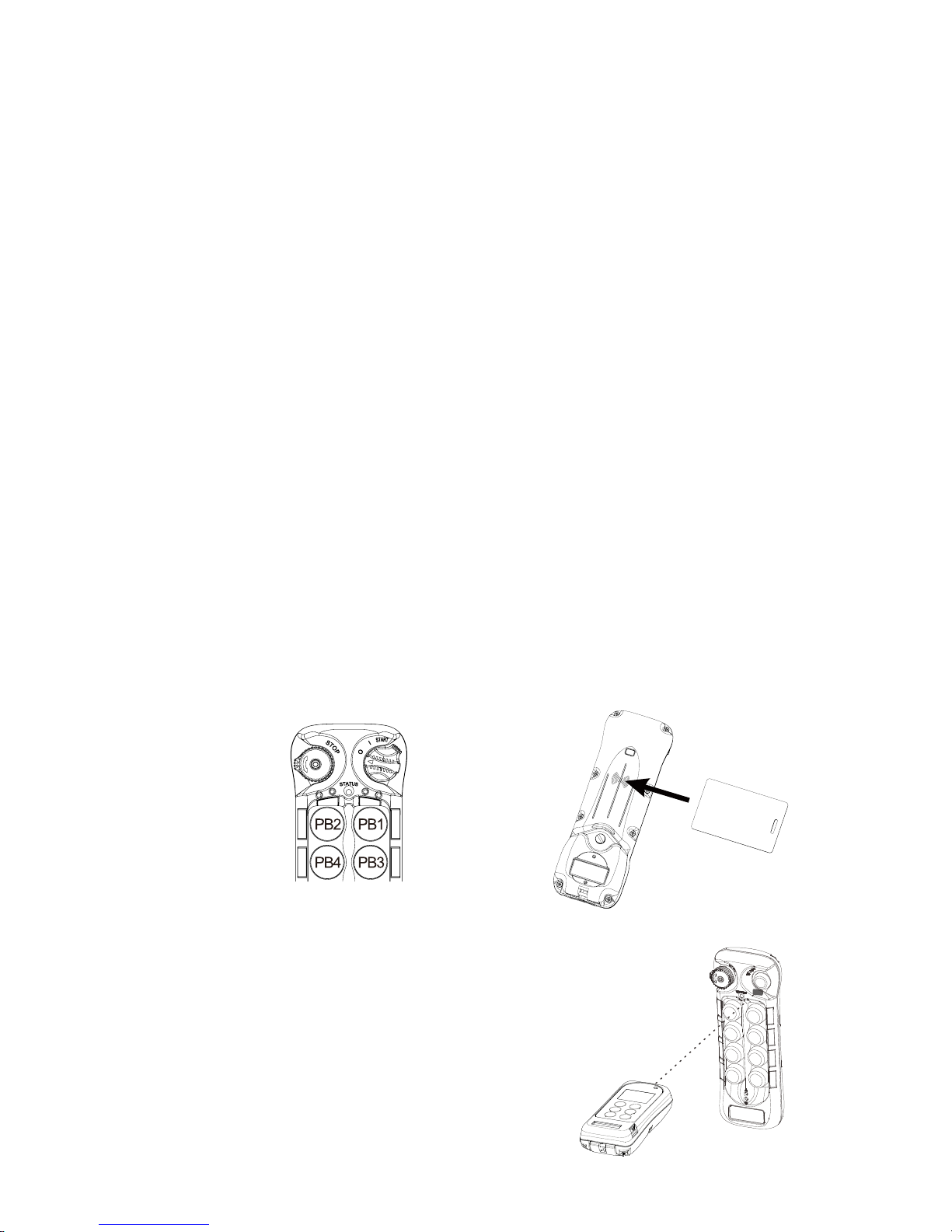
Page 76
9.55 Program Output Frequency (RX)
1) Make sure the I-Chip is connected to the programmer.
2) Press “→” button to enter Output Frequency setting.
3) Press “↑” and “↓” button to scroll and select from various frequency.
4) Exit Program Output Frequency by pressing the “BACK” button until the
cursor is shown next to “OUT FREQ”.
5) Press “↑” and “↓” button to scroll through other Flex EP-H settings.
10. Transmitter Access Card (TAC)
1) Rotate the power switch key to OFF ( 0 ) position.
2) With the STOP button elevated, press and hold PB1, PB2, PB3 and PB4 at
the same time.
3) Rotate the power switch key to ON ( I ) position.
4) Let go PB1, PB2, PB3 and PB4 at the same time, the Status LED displays
orange fast blinks (entered TAC mode).
5) Placed the access card over the RFID marking located on the backside of
the transmitter.
6) Status LED with 1 second green means the access card is being
programmed into the transmitter.
7) Status LED with 1 second orange means the access card is already
programmed into the transmitter.
8) Status LED with 1 second red means unable to store any more access
cards. Each transmitter can only store up to 16 access cards.
9) When all access cards are stored into the
transmitter use the IR programmer to
extract all access cards info by pointing the
infrared sensor towards the transmitter
Status LED location within a distance of no
more than 10cm.
Page 78

Page 77
10) Press “→” button to enter TAC setting
11) Press READ button to transfer all access cards info into the IR
programmer for further programming. If the screen shows “READ OK” the
transfer is completed.
12) After entering the TAC setting the first screen you see is either “EMPTY”
(no access cards) or “_ CARDS” (number of access cards) + “DEL_ALL”
(delete all) command.
13) Select “DEL_ALL” by pressing “→” button one time if you want to delete all
access cards from the system. Press “→” button again to delete.
14) Press “↑” and “↓” button if you want to program the access cards.
15) “CARD 1” shown on the screen is always the last access card scanned
into the transmitter.
16) Press “↑” and “↓” button to select which access card to program and then
press “→” button to enter.
17) A mix of alphabets and numbers shown on the second line below the
access card number is the access card ID number.
18) The next line (S1234567) is the transmitter function. “S” is for START
(access card required after transmitter power on), “1” for PB1, “2” for PB2,
“3” for PB3, etc… The third line (89101112) is for PB8 through PB12.
19) Press “→” button to go to the first digit from the left and press “↑” and “↓”
button to assign or un-assign. Assigned is represented by black color
background with white “S” or number 1~12.
20) When “S” (START) is assigned on one of the access card, the same “S”
START function on all other access cards is also assigned automatically.
The pushbutton functions can be individually assigned.
21) Press “→” button to go to the next column to the right and redo step 19.
22) Program other access cards by pressing the “BACK” button until the
cursor is shown next to “CARD # and redo step 16.
23) When all access cards are programmed, use the IR programmer to
transfer all access card info back to the transmitter by pointing the infrared
sensor towards the transmitter Status LED location within a distance of no
more than 10cm and press the “WRITE” button. In order for the
transmitter to receive TAC info back from the IR programmer it must be in
the TAC mode as well (refer to step 1 through 4). If the screen shows
“WRITE OK” the transfer is completed.
24) Exit Program TAC by pressing the “BACK” button until the cursor is
shown next to “TAC”.
Page 79
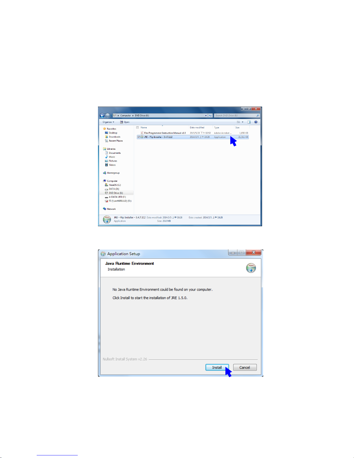
Page 78
11. Firmware Update
11.1 Install Software
Install the provided software
Page 80
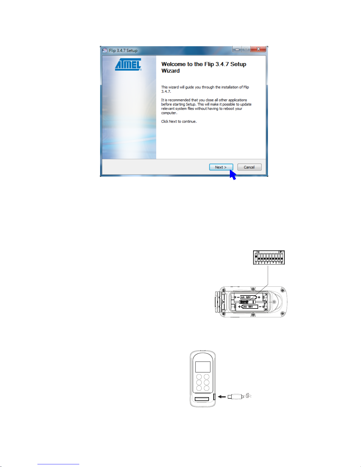
Page 79
11.2 Firmware Update
11.2.1 Set dipswitch position #1 to “ON” or “1”
11.2.2 Plug in the USB cable
Page 81
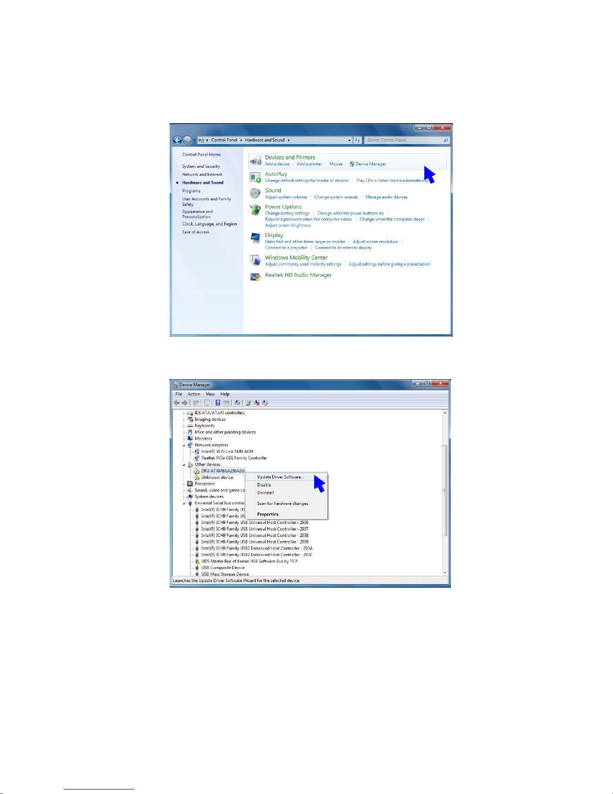
Page 80
11.2.3 Please try the following if device can not be found when plug in
the USB onto you computer
Page 82
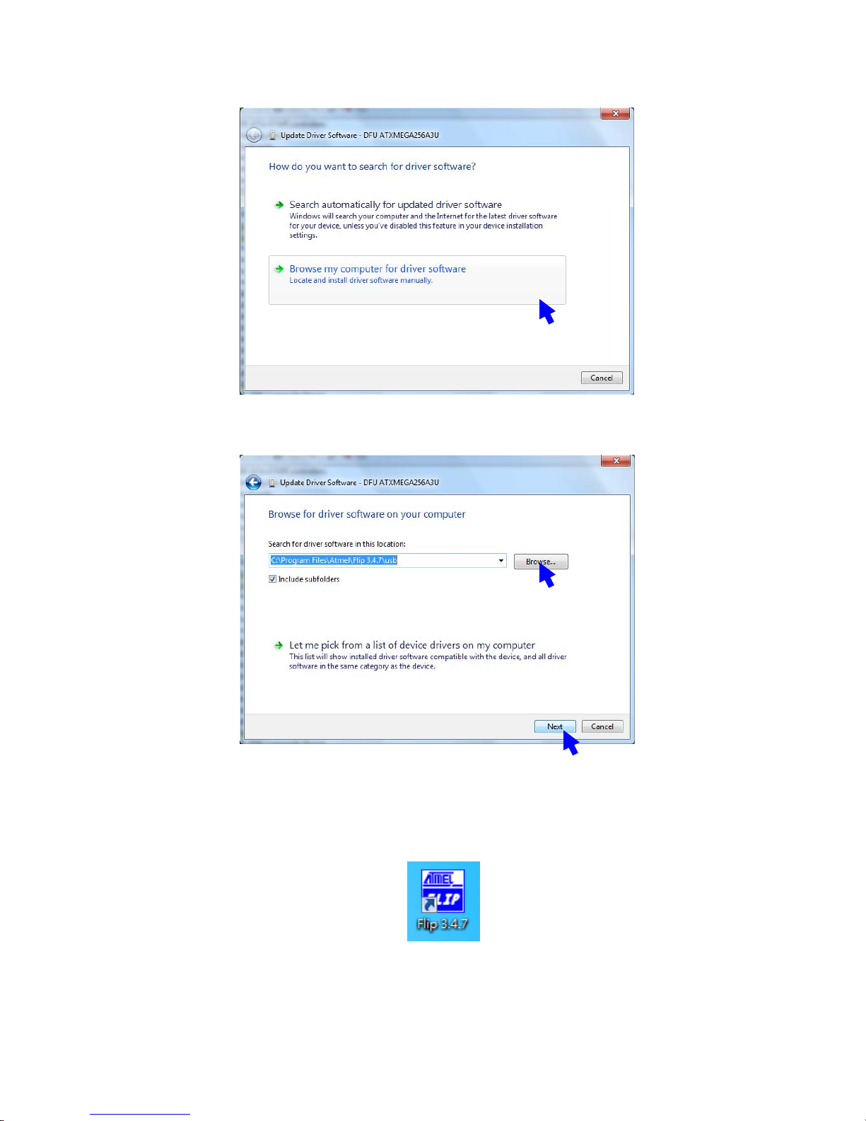
Page 81
11.2.4 Open Flip 3.4.7
Page 83
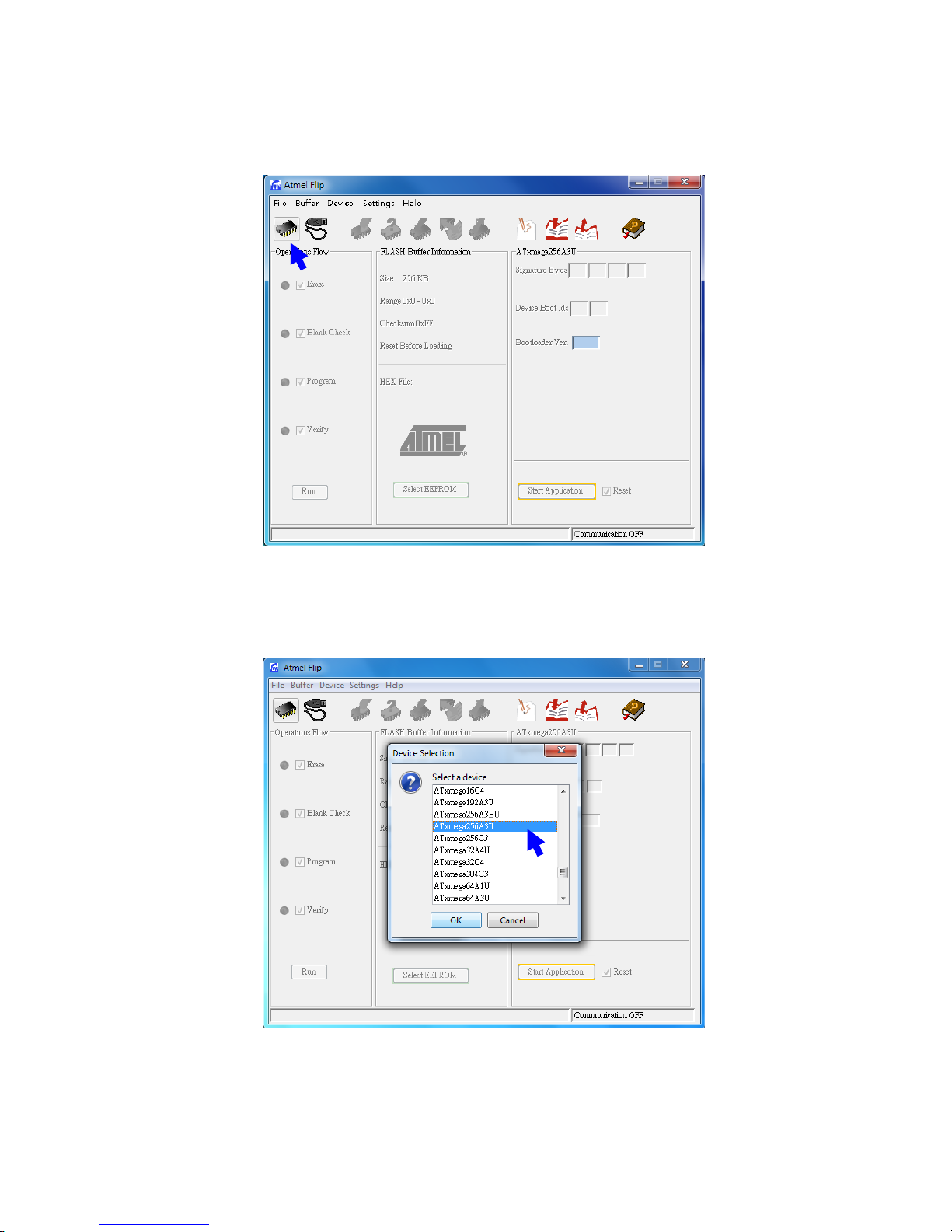
Page 82
11.2.5 Select a target device
11.2.6 Select ATxmega256A3U
Page 84
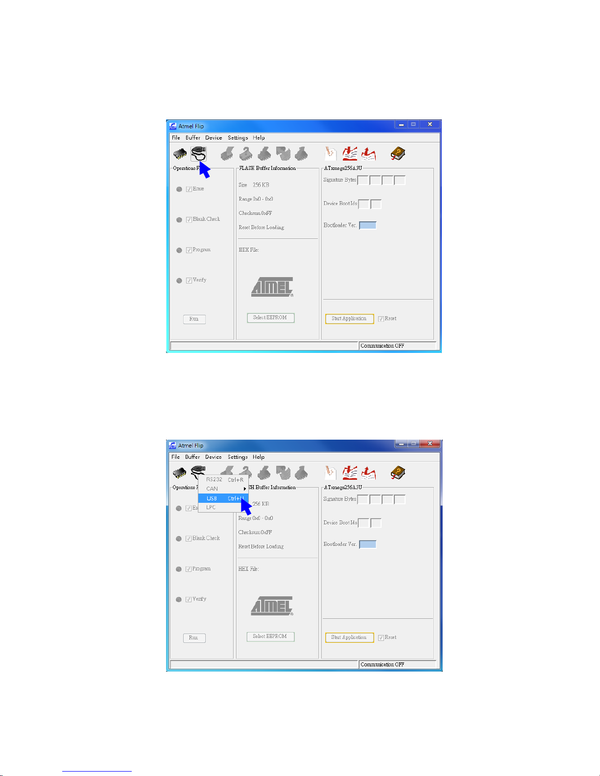
Page 83
11.2.7 Select a communication medium
11.2.8 Select USB
Page 85
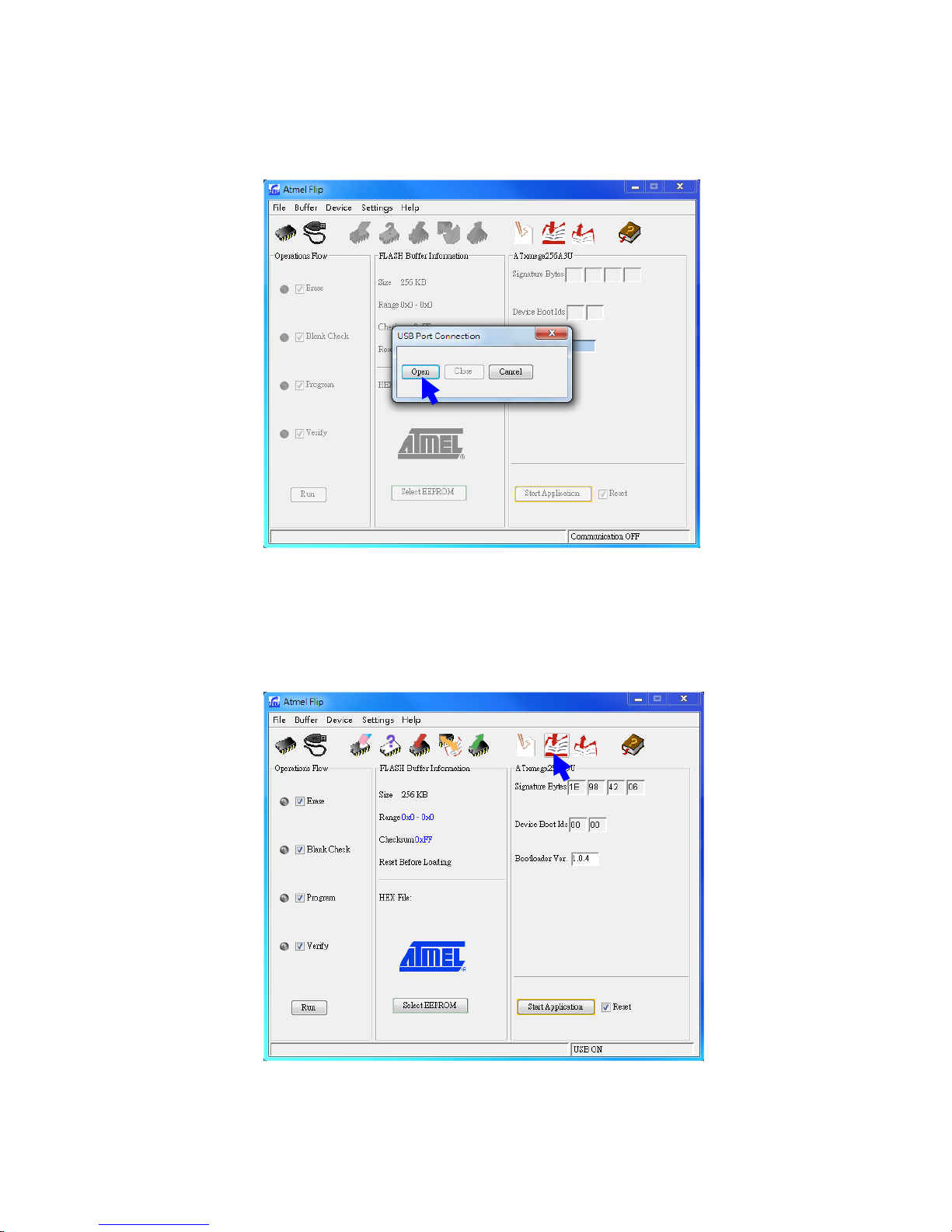
Page 84
11.2.9 Open USB
11.2.10 Load HEX file
Page 86
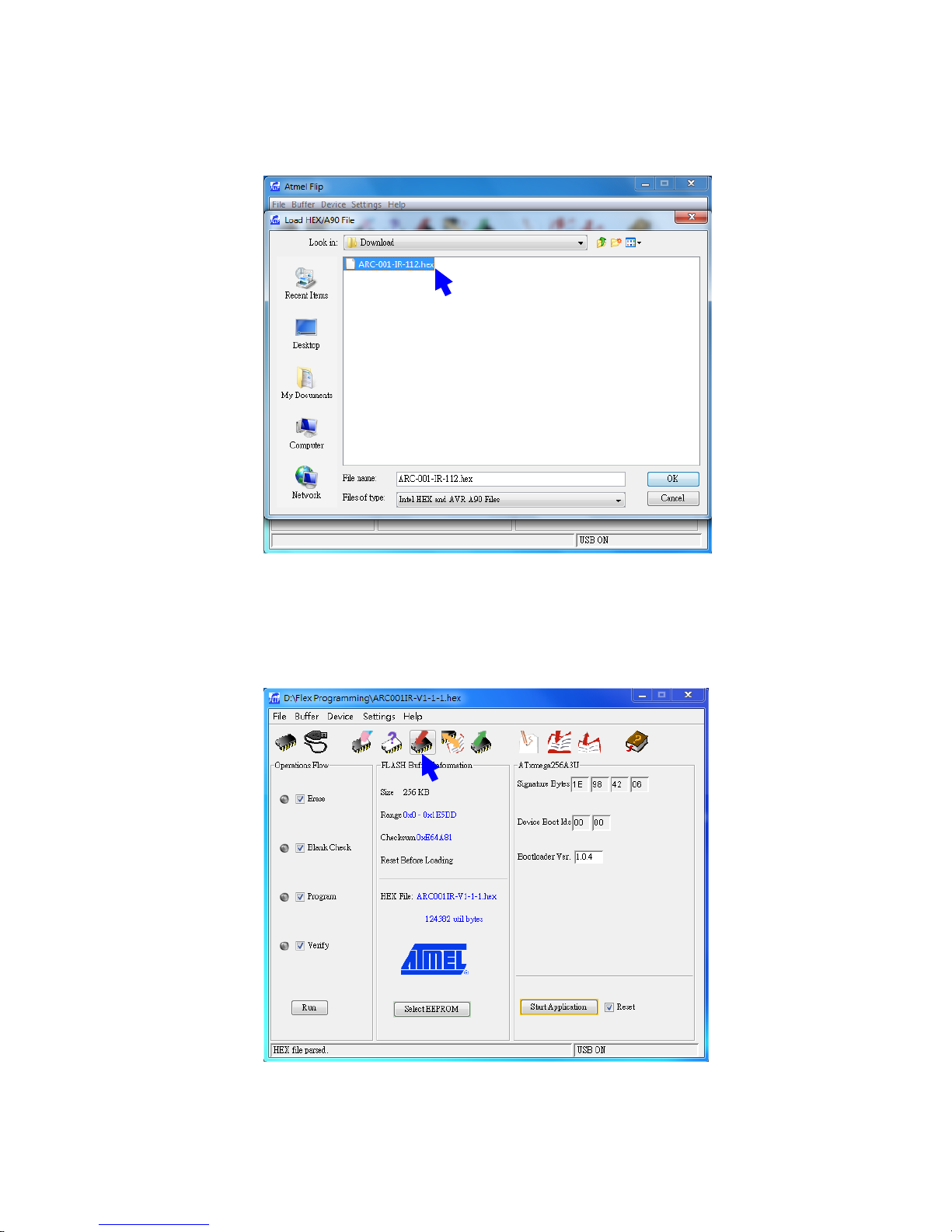
Page 85
11.2.11 Select HEX file (downloaded from ARC website)
11.2.12 Program target device memory
Page 87
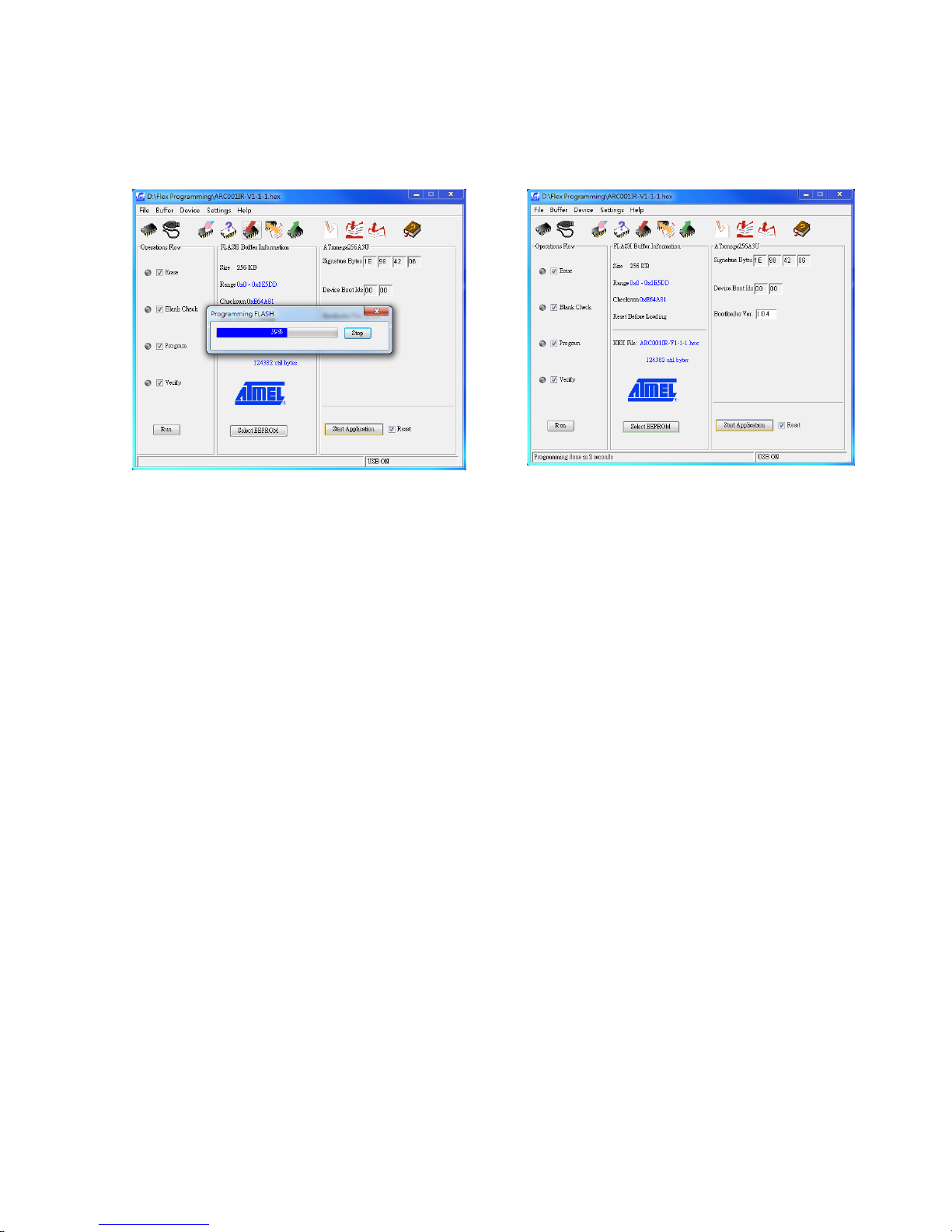
Page 86
11.2.13 Download and Complete
→
11.2.14 Unplug the USB cable and set dipswitch position #1 back to
“Off”or “0”.
Page 88
Page 87
12. Pushbutton Function Table
A. Flex EX Models
A. Transmitter Toggle Functions (Standard)
NO Dip Set PB1 PB2 PB3 PB4 PB5 PB6 PB7 PB8 PB9 PB10 PB11 PB12
001
00000001
4
002
00000010
3 4
003
00000011
2 3 4
004
00000100
1 2 3 4
005
00000101
4
006
00000110
3 4
007
00000111
2 3 4
008
00001000
1 2 3 4
009
00001001
4
010
00001010
3 4
011
00001011
2 3 4
012
00001100
1 2 3 4
013
00001101
4
014
00001110
3 4
015
00001111
2 3 4
016
00010000
1 2 3 4
Page 89

Page 88
B. Transmitter Toggle Functions (Inline)
NO Dip Set PB1 PB2 PB3 PB4 PB5 PB6 PB7 PB8 PB9 PB10 PB11 PB12
01
00000001
4
017
00010001
3 4
018
00010010
2 3 4
019
00010011
1 2 3 4
005
00000101
4
020
00010100
3 4
021
00010101
2 3 4
022
00010110
1 2 3 4
005
00000101
4
020
00010100
3 4
021
00010101
2 3 4
022
00010110
1 2 3 4
009
00001001
4
023
00010111
3 4
024
00011000
2 3 4
025
00011001
1 2 3 4
013
00001101
4
026
00011010
3 4
027
00011011
2 3 4
028
00011100
1 2 3 4
Page 90

Page 89
C. A/B Pushbutton Select Functions (Standard)
Type-A selector sequence : A+B → A → B → A+B …
Type-B selector sequence : Off → A → B → Off → A → B …
Type-C selector sequence : A → B → A+B → A → B → A+B …
Type-D selector sequence : Off → A → B → A+B → Off → A → B → A+B …
NO Dip Set PB1 PB2 PB3 PB4 PB5 PB6 PB7 PB8 PB9 PB10 PB11 PB12
029
00011101
A/1.2
030
00011110
B/1.2
031
00011111
C/1.2
032
00100000
D/1.2
033
00100001
A/3.4
034
00100010
B/3.4
035
00100011
C/3.4
036
00100100
D/3.4
037
00100101
A/1.2 A/3.4
038
00100110
A/1.2 B/3.4
039
00100111
A/1.2 C/3.4
040
00101000
A/1.2 D/3.4
041
00101001
B/1.2 B/3.4
042
00101010
B/1.2 C/3.4
043
00101011
B/1.2 D/3.4
044
00101100
C/1.2 C/3.4
045
00101101
C/1.2 D/3.4
046
00101110
D/1.2 D/3.4
047
00101111
A/1.2
048
00110000
B/1.2
049
00110001
C/1.2
050
00110010
D/1.2
Page 91

Page 90
NO Dip Set PB1 PB2 PB3 PB4 PB5 PB6 PB7 PB8 PB9 PB10 PB11 PB12
051
00110011
A/3.4
052
00110100
B/3.4
053
00110101
C/3.4
054
00110110
D/3.4
055
00110111
A/1.2 A/3.4
056
00111000
A/1.2 B/3.4
057
00111001
A/1.2 C/3.4
058
00111010
A/1.2 D/3.4
059
00111011
B/1.2 B/3.4
060
00111100
B/1.2 C/3.4
061
00111101
B/1.2 D/3.4
062
00111110
C/1.2 C/3.4
063
00111111
C/1.2 D/3.4
064
01000000
D/1.2 D/3.4
065
01000001
A/1.2
066
01000010
B/1.2
067
01000011
C/1.2
068
01000100
D/1.2
069
01000101
A/3.4
070
01000110
B/3.4
071
01000111
C/3.4
072
01001000
D/3.4
073
01001001
A/1.2 A/3.4
074
01001010
A/1.2 B/3.4
075
01001011
A/1.2 C/3.4
Page 92

Page 91
NO Dip Set PB1 PB2 PB3 PB4 PB5 PB6 PB7 PB8 PB9 PB10 PB11 PB12
076
01001100
A/1.2 D/3.4
077
01001101
B/1.2 B/3.4
078
01001110
B/1.2 C/3.4
079
01001111
B/1.2 D/3.4
080
01010000
C/1.2 C/3.4
081
01010001
C/1.2 D/3.4
082
01010010
D/1.2 D/3.4
083
01010011
A/1.2
084
01010100
B/1.2
085
01010101
C/1.2
086
01010110
D/1.2
087
01010111
A/3.4
088
01011000
B/3.4
089
01011001
C/3.4
090
01011010
D/3.4
091
01011011
A/1.2 A/3.4
092
01011100
A/1.2 B/3.4
093
01011101
A/1.2 C/3.4
094
01011110
A/1.2 D/3.4
095
01011111
B/1.2 B/3.4
096
01100000
B/1.2 C/3.4
097
01100001
B/1.2 D/3.4
098
01100010
C/1.2 C/3.4
099
01100011
C/1.2 D/3.4
100
01100100
D/1.2 D/3.4
Page 93

Page 92
D. A/B Pushbutton Select Functions (Inline)
Type-A selector sequence : A+B → A → B → A+B …
Type-B selector sequence : Off → A → B → Off → A → B …
Type-C selector sequence : A → B → A+B → A → B → A+B …
Type-D selector sequence : Off → A → B → A+B → Off → A → B → A+B …
NO Dip Set PB1 PB2 PB3 PB4 PB5 PB6 PB7 PB8 PB9 PB10 PB11 PB12
101
01100101
A/1.2
102
01100110
B/1.2
103
01100111
C/1.2
104
01101000
D/1.2
033
00100001
A/3.4
034
00100010
B/3.4
035
00100011
C/3.4
036
00100100
D/3.4
105
01101001
A/1.2 A/3.4
106
01101010
A/1.2 B/3.4
107
01101011
A/1.2 C/3.4
108
01101100
A/1.2 D/3.4
109
01101101
B/1.2 B/3.4
110
01101110
B/1.2 C/3.4
111
01101111
B/1.2 D/3.4
112
01110000
C/1.2 C/3.4
113
01110001
C/1.2 D/3.4
114
01110010
D/1.2 D/3.4
115
01110011
A/1.2
116
01110100
B/1.2
117
01110101
C/1.2
118
01110110
D/1.2
.
Page 94

Page 93
NO Dip Set PB1 PB2 PB3 PB4 PB5 PB6 PB7 PB8 PB9 PB10 PB11 PB12
051
00110011
A/3.4
052
00110100
B/3.4
053
00110101
C/3.4
054
00110110
D/3.4
119
01110111
A/1.2 A/3.4
120
01111000
A/1.2 B/3.4
121
01111001
A/1.2 C/3.4
122
01111010
A/1.2 D/3.4
123
01111011
B/1.2 B/3.4
124
01111100
B/1.2 C/3.4
125
01111101
B/1.2 D/3.4
126
01111110
C/1.2 C/3.4
127
01111111
C/1.2 D/3.4
128
10000000
D/1.2 D/3.4
115
01110011
A/1.2
116
01110100
B/1.2
117
01110101
C/1.2
118
01110110
D/1.2
051
00110011
A/3.4
052
00110100
B/3.4
053
00110101
C/3.4
054
00110110
D/3.4
119
01110111
A/1.2 A/3.4
120
01111000
A/1.2 B/3.4
121
01111001
A/1.2 C/3.4
Page 95

Page 94
NO Dip Set PB1 PB2 PB3 PB4 PB5 PB6 PB7 PB8 PB9 PB10 PB11 PB12
122
01111010
A/1.2 D/3.4
123
01111011
B/1.2 B/3.4
124
01111100
B/1.2 C/3.4
125
01111101
B/1.2 D/3.4
126
01111110
C/1.2 C/3.4
127
01111111
C/1.2 D/3.4
128
10000000
D/1.2 D/3.4
129
10000001
A/1.2
130
10000010
B/1.2
131
10000011
C/1.2
132
10000100
D/1.2
069
01000101
A/3.4
070
01000110
B/3.4
071
01000111
C/3.4
072
01001000
D/3.4
133
10000101
A/1.2 A/3.4
134
10000110
A/1.2 B/3.4
135
10000111
A/1.2 C/3.4
136
10001000
A/1.2 D/3.4
137
10001001
B/1.2 B/3.4
138
10001010
B/1.2 C/3.4
139
10001011
B/1.2 D/3.4
140
10001100
C/1.2 C/3.4
141
10001101
C/1.2 D/3.4
142
10001110
D/1.2 D/3.4
Page 96

Page 95
NO Dip Set PB1 PB2 PB3 PB4 PB5 PB6 PB7 PB8 PB9 PB10 PB11 PB12
143
10001111
A/1.2
144
10010000
B/1.2
145
10010001
C/1.2
146
10010010
D/1.2
087
01010111
A/3.4
088
01011000
B/3.4
089
01011001
C/3.4
090
01011010
D/3.4
147
10010011
A/1.2 A/3.4
148
10010100
A/1.2 B/3.4
149
10010101
A/1.2 C/3.4
150
10010110
A/1.2 D/3.4
151
10010111
B/1.2 B/3.4
152
10011000
B/1.2 C/3.4
153
10011001
B/1.2 D/3.4
154
10011010
C/1.2 C/3.4
155
10011011
C/1.2 D/3.4
156
10011100
D/1.2 D/3.4
Page 97

Page 96
E. Transmitter Toggle + A/B Pushbutton Select Functions (Standard)
NO Dip Set PB1 PB2 PB3 PB4 PB5 PB6 PB7 PB8 PB9 PB10 PB11 PB12
157
10011101
1 A/3.4
158
10011110
1 B/3.4
159
10011111
1 C/3.4
160
10100000
1 D/3.4
161
10100001
1 2 A/3.4
162
10100010
1 2 B/3.4
163
10100011
1 2 C/3.4
164
10100100
1 2 D/3.4
165
10100101
A/1.2 4
166
10100110
B/1.2 4
167
10100111
C/1.2 4
168
10101000
D/1.2 4
169
10101001
3 A/1.2 4
170
10101010
3 B/1.2 4
171
10101011
3 C/1.2 4
172
10101100
3 D/1.2 4
173
10101101
1 A/3.4
174
10101110
1 B/3.4
175
10101111
1 C/3.4
176
10110000
1 D/3.4
177
10110001
1 2 A/3.4
178
10110010
1 2 B/3.4
179
10110011
1 2 C/3.4
180
10110100
1 2 D/3.4
181
10110101
A/1.24
Page 98

Page 97
NO Dip Set PB1 PB2 PB3 PB4 PB5 PB6 PB7 PB8 PB9 PB10 PB11 PB12
182
10110110
B/1.2 4
183
10110111
C/1.2 4
184
10111000
D/1.2 4
185
10111001
3 A/1.2 4
186
10111010
3 B/1.2 4
187
10111011
3 C/1.2 4
188
10111100
3 D/1.2 4
189
10111101
1 A/3.4
190
10111110
1 B/3.4
191
10111111
1 C/3.4
192
11000000
1 D/3.4
193
11000001
1 2 A/3.4
194
11000010
1 2 B/3.4
195
11000011
1 2 C/3.4
196
11000100
1 2 D/3.4
197
11000101
A/1.2 4
198
11000110
B/1.2 4
199
11000111
C/1.2 4
200
11001000
D/1.2 4
201
11001001
3 A/1.2 4
202
11001010
3 B/1.2 4
203
11001011
3 C/1.2 4
204
11001100
3 D/1.2 4
205
11001101
1 A/3.4
206
11001110
1 B/3.4
Page 99
Page 98
NO Dip Set PB1 PB2 PB3 PB4 PB5 PB6 PB7 PB8 PB9 PB10 PB11 PB12
207
11001111
1 C/3.4
208
11010000
1 D/3.4
209
11010001
1 2 A/3.4
210
11010010
1 2 B/3.4
211
11010011
1 2 C/3.4
212
11010100
1 2 D/3.4
213
11010101
A/1.2 4
214
11010110
B/1.2 4
215
11010111
C/1.2 4
216
11011000
D/1.2 4
217
11011001
3 A/1.2 4
218
11011010
3 B/1.2 4
219
11011011
3 C/1.2 4
220
11011100
3 D/1.2 4
Page 100

Page 99
F. Transmitter Toggle + A/B Pushbutton Select Functions (Inline)
NO Dip Set PB1 PB2 PB3 PB4 PB5 PB6 PB7 PB8 PB9 PB10 PB11 PB12
221
11011101
1 A/3.4
222
11011110
1 B/3.4
223
11011111
1 C/3.4
224
11100000
1 D/3.4
225
11100001
1 2 A/3.4
226
11100010
1 2 B/3.4
227
11100011
1 2 C/3.4
228
11100100
1 2 D/3.4
229
11100101
1 A/3.4
230
11100110
1 B/3.4
231
11100111
1 C/3.4
232
11101000
1 D/3.4
233
11101001
1 2 A/3.4
234
11101010
1 2 B/3.4
235
11101011
1 2 C/3.4
236
11101100
1 2 D/3.4
229
11101101
1 A/3.4
230
11101110
1 B/3.4
231
11101111
1 C/3.4
232
11110000
1 D/3.4
233
11110001
1 2 A/3.4
234
11110010
1 2 B/3.4
235
11110011
1 2 C/3.4
236
11110100
1 2 D/3.4
237
11110101
1 A/3.4
 Loading...