

Page 1
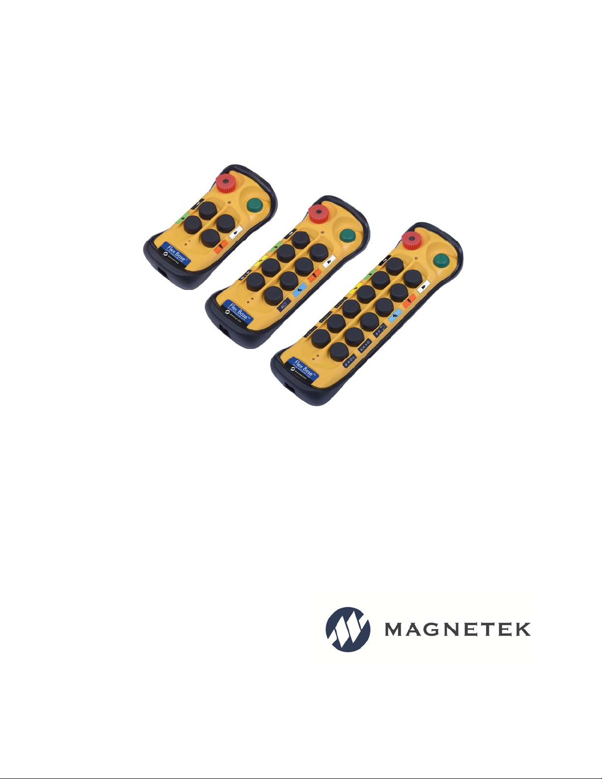
Flex 4Base®
Radio Control Equipment
Instruction Manual
191-90300-3204 R1
January 2017
© Copyright 2017 Magnetek
Page 2

Your New Radio Remote Control System
Thank you for your purchase of Magnetek’s Flex Base® Radio Remote Equipment Control. Magnetek
has set a whole new standard in radio-remote performance, dependability, and value with this unique new
line of handheld transmitters.
If your product ever needs modification or service, please contact one of our representatives at the
following locations:
U.S. Service Information
For questions regarding service or technical information contact:
+1.866.MAG.SERV
+1.866.624.7378
International Service
+1.262.783.3500
World Headquarters:
Magnetek, Inc.
N49 W13650 Campbell Drive
Menomonee Falls, WI 53051
Fax Numbers:
Main: +1.800.298.3503
Sales: +1.262.783.3510
Service: +1.262.783.3508
Canada Service Information:
161 Orenda Road
Unit 1
Brampton, Ontario
L6W 1W3 Canada
Phone: +1.800.792.7253
Fax: +1.905.828.5707
+1.416.424.7617 (24/7 Service pager)
©2017 MAGNETEK
All rights reserved. This notice applies to all copyrighted materials included with this product, including,
but not limited to, this manual and software embodied within the product. This manual is intended for the
sole use of the person(s) to whom it was provided, and any unauthorized distribution of the manual or
dispersal of its contents is strictly forbidden. This manual may not be reproduced in whole or in part by
any means whatsoever without the expressed written permission of MAGNETEK.
EU Market Contact:
Brian Preston
Magnetek (UK) Ltd.
Unit 3 Bedford Business Centre
Mile Road
Bedford, MK42 9TW UK
Phone: +44.1234.349191
Fax: +44.1234.268955
Flex 4Base® CE Instruction Manual
January 2017
Page 2 of 41
Page 3
PRODUCT MANUAL SAFETY INFORMATION
Magnetek, Inc. (Magnetek) offers a broad range of radio remote control products, control products and
adjustable frequency drives, and industrial braking systems for overhead material handling applications.
This manual has been prepared by Magnetek to provide information and recommendations for the
installation, use, operation and service of Magnetek’s material handling products and systems (Magnetek
Products). Anyone who uses, operates, maintains, services, installs or owns Magnetek Products should
know, understand and follow the instructions and safety recommendations in this manual for Magnetek
Products.
The recommendations in this manual do not take precedence over any of the following requirements
relating to cranes, hoists and lifting devices:
Instructions, manuals, and safety warnings of the manufacturers of the equipment where the
radio system is used,
Plant safety rules and procedures of the employers and the owners of facilities where the
Magnetek Products are being used,
Regulations issued by the Occupational Health and Safety Administration (OSHA),
Applicable local, state or federal codes, ordinances, standards and requirements, or
Safety standards and practices for the overhead material handling industry.
This manual does not include or address the specific instructions and safety warnings of these
manufacturers or any of the other requirements listed above. It is the responsibility of the owners, users
and operators of the Magnetek Products to know, understand and follow all of these requirements. It is
the responsibility of the owner of the Magnetek Products to make its employees aware of all of the above
listed requirements and to make certain that all operators are properly trained. No one should use
Magnetek Products prior to becoming familiar with and being trained in these requirements.
WARRANTY INFORMATION
FOR INFORMATION ON MAGNETEK’S PRODUCT WARRANTIES BY PRODUCT TYPE, PLEASE
VISIT WWW.MAGNETEK.COM.
Flex 4Base® CE Instruction Manual
January 2017
Page 3 of 41
Page 4

Table of Contents
1 Introduction ................................................................................................................................................ 5
2 Radio Controlled Safety ............................................................................................................................. 6
2.1 Critical Installation Considerations...................................................................................................... 7
2.2 General ............................................................................................................................................... 7
2.3 Persons Authorized to Operate Radio Controlled Cranes .................................................................. 7
2.4 Safety Information and Recommended Training for Radio Controlled Equipment Operators ........... 8
2.5 Transmitter Unit .................................................................................................................................. 9
2.6 Pre-Operation Test .............................................................................................................................. 9
2.7 Handling Batteries ............................................................................................................................ 10
2.8 Optional Rechargeable Battery Charging ......................................................................................... 10
2.9 Battery Disposal ................................................................................................................................ 10
2.10 Crane/Lifting Device Specific Warnings .......................................................................................... 11
3 General System Information .................................................................................................................... 12
3.1 Transmitter ........................................................................................................................................ 12
3.1.1 External Illustration .................................................................................................................... 12
3.1.2 Internal Illustration ..................................................................................................................... 13
3.2 Receiver ............................................................................................................................................ 14
3.2.1 External Illustration .................................................................................................................... 14
3.2.2 Internal Illustration ..................................................................................................................... 15
4 Function Settings ..................................................................................................................................... 16
4.1 Transmitter ........................................................................................................................................ 16
4.1.1 Transmitter Firmware Version ................................................................................................... 16
4.1.2 Transmitter Channel Settings .................................................................................................... 16
4.1.3 Remote Pairing .......................................................................................................................... 17
4.1.4 Transmitter Start Function Settings ........................................................................................... 19
4.1.5 Transmitter Inactivity Timer Settings ......................................................................................... 19
4.1.6 Transmitter Output Power Settings ........................................................................................... 19
4.1.7 Infrared Programming ............................................................................................................... 20
4.1.8 Pushbutton Function Settings ................................................................................................... 20
4.2 Receiver ............................................................................................................................................ 22
4.2.1 Receiver Channel Settings ........................................................................................................ 22
4.2.2 Output Relay Configurations ..................................................................................................... 23
4.2.3 Dipswitch Settings ..................................................................................................................... 27
4.2.4 Jumper Settings ........................................................................................................................ 29
4.2.5 Fuse Ratings ............................................................................................................................. 29
4.2.6 Lights Indicator and Buzzer Installation ..................................................................................... 30
4.2.7 Other Function Output Relays Settings ..................................................................................... 30
5 System Channels Table ........................................................................................................................... 31
6 Receiver Installation ................................................................................................................................. 32
6.1 Output Relay Contact Diagrams ....................................................................................................... 32
6.2 Pre-installation Precautions .............................................................................................................. 32
6.3 Step-By-Step Installation ................................................................................................................... 33
7 Operating Procedures .............................................................................................................................. 36
7.1 General Operation ............................................................................................................................ 36
7.2 A/B Pushbutton Select Operation ..................................................................................................... 37
7.3 Pitch & Catch Operation ................................................................................................................... 37
7.4 Changing Batteries ........................................................................................................................... 37
7.5 System Status Light Indications ........................................................................................................ 38
7.5.1 Transmitter Status Indications ................................................................................................... 38
7.5.2 Receiver Status Indications ....................................................................................................... 39
7.5.3 Receiver Power Indications ....................................................................................................... 39
7.5.4 Receiver COM Indications ......................................................................................................... 39
8 General Specifications ............................................................................................................................. 40
9 EU Declaration of Conformity .................................................................................................................. 41
Flex 4Base® CE Instruction Manual
January 2017
Page 4 of 41
Page 5

1 Introduction
The Flex Base radio remote control systems are designed for control of industrial equipment and
machinery such as overhead traveling cranes, jib cranes, gantry cranes, tower cranes, electric hoists,
winches, monorails, conveyor belts, mining equipment, and all other material handling equipment where
wireless control is preferred.
Each Flex Base system consists of a transmitter handset and a receiver unit. Other standard-equipped
accessories include transmitter lanyard, vinyl pouch, pushbutton labels, output cable, and instruction
manual CD.
List of notable features include:
62 user-programmable channels – advanced synthesized RF controls with 62 built-in
programmable channels set via pushbuttons and dipswitches.
Wireless remote pairing function – system pairing and cloning can be done easily and wirelessly.
Over one million unique address codes (20bit) – each and every Flex Base system has its own
address code and serial number, never repeats.
Advanced controls – the Flex Base system utilizes dual advanced microprocessor controls with
32bit CRC and Hamming Code, which provide ultra-fast, safe, precise, and error-free encoding
and decoding.
Two-way transmission – transmitter and receiver communicate with one another for safe, precise
and uninterrupted operation.
Reliable pushbuttons – the pushbuttons are rated for more than one million press cycles.
Low power consumption – requires only two “AA” Alkaline batteries for more than 150 hours of
uninterrupted operation between replacements.
Ultra-durable nylon and fiberglass composite enclosures – highly resistance to breakage and
deformation even in the most abusive environments. The receiver enclosures and output cables
are UL94-V0 rated.
Fully sealed enclosures – the transmitter and receiver enclosures are IP66 rated.
Full compliance – all systems are fully complied with the FCC Part-15 Rules and European Safety
Standards.
Other optional accessories and features – transmitter magnet mount, transmitter waist belt, 2 and
3 positions rotary switches, transmitter rubber guards, miniature indicator lights and buzzer, dualcrane tandem function, multi-crane random access function, and many others.
Flex 4Base® CE Instruction Manual
January 2017
Page 5 of 41
Page 6
2 Radio Controlled Safety
WARNINGS and CAUTIONS
Throughout this document WARNING and CAUTION statements have been deliberately placed to
highlight items critical to the protection of personnel and equipment.
WARNING – A warning highlights an essential operating or maintenance procedure, practice, etc. which, if
not strictly observed, could result in injury or death of personnel, or long term physical hazards. Warnings
are highlighted as shown below:
WARNING
CAUTION – A caution highlights an essential operating or maintenance procedure, practice, etc. which if not
strictly observed, could result in damage to, or destruction of equipment, or loss of functional effectiveness.
Cautions are highlighted as shown below:
CAUTION
WARNINGS and CAUTIONS SHOULD NEVER BE DISREGARDED.
The safety rules in this section are not intended to replace any rules or regulations of any applicable local, state, or
federal governing organizations. Always follow your local lockout and tagout procedure when maintaining any radio
equipment. The following information is intended to be used in conjunction with other rules or regulations already in
existence. It is important to read all of the safety information contained in this section before installing or operating the
Radio Control System.
Flex 4Base® CE Instruction Manual
January 2017
Page 6 of 41
Page 7
2.1 Critical Installation Considerations
WARNING
PRIOR TO INSTALLATION AND OPERATION OF THIS EQUIPMENT, READ AND DEVELOP AN UNDERSTANDING
OF THE CONTENTS OF THIS MANUAL AND THE OPERATION MANUAL OF THE EQUIPMENT OR DEVICE TO
WHICH THIS EQUIPMENT WILL BE INTERFACED. FAILURE TO FOLLOW THIS WARNING COULD RESULT IN
SERIOUS INJURY OR DEATH AND DAMAGE TO EQUIPMENT.
FOLLOW YOUR LOCAL LOCKOUT TAGOUT PROCEDURE BEFORE MAINTAINING ANY REMOTE
CONTROLLED EQUIPMENT. ALWAYS REMOVE ALL ELECTRICAL POWER FROM THE EQUIPMENT BEFORE
ATTEMPTING ANY INSTALLATION PROCEDURES. DE-ENERGIZE AND TAGOUT ALL SOURCES OF
ELECTRICAL POWER BEFORE TOUCH-TESTING ANY EQUIPMENT. FAILURE TO FOLLOW THIS WARNING
COULD RESULT IN SERIOUS INJURY OR DEATH AND DAMAGE TO EQUIPMENT.
AFTER INSTALLATION BE SURE TO VERIFY THAT THE TRANSMITTER IS NOT INTERFERING WITH OTHER
EQUIPMENT IN THE AREA. ALSO VERIFY THAT OTHER EQUIPMENT IS NOT INTERFERING WITH THE
TRANSMITTER AND ITS ASSOCIATED EQUIPMENT. FAILURE TO FOLLOW THESE WARNINGS COULD
RESULT IN SERIOUS INJURY OR DEATH AND DAMAGE TO EQUIPMENT.
2.2 General
Radio controlled equipment operates in several directions. Quite frequently, the equipment is operated in areas where
people are working in close proximity to the equipment. The operator must exercise extreme caution at all times.
Workers must constantly be alert to avoid accidents. The following recommendations have been included to indicate
how careful and thoughtful actions may prevent injuries, damage to equipment, or even save a life.
2.3 Persons Authorized to Operate Radio Controlled
Cranes
Only properly trained persons designated by management should be permitted to operate radio controlled equipment.
Radio controlled equipment should not be operated by any person who cannot read or understand signs, notices and
operating instructions that pertain to the equipment.
Radio controlled equipment should not be operated by any person with insufficient eyesight or hearing or by any
person who may be suffering from a disorder or illness, is taking any medication that may cause loss of equipment
control, or is under the influence of alcohol or drugs.
Flex 4Base® CE Instruction Manual
January 2017
Page 7 of 41
Page 8

2.4 Safety Information and Recommended Training for
Radio Controlled Equipment Operators
Anyone being trained to operate radio controlled equipment should possess as a minimum the following knowledge
and skills before using the radio controlled equipment.
The operator should:
have knowledge of hazards pertaining to equipment operation
have knowledge of safety rules for radio controlled equipment
have the ability to judge distance of moving objects
know how to properly test prior to operation
be trained in the safe operation of the radio transmitter as it pertains to the equipment being operated
have knowledge of the use of equipment warning lights and alarms
have knowledge of the proper storage space for a radio control transmitter when not in use
be trained in transferring a radio control transmitter to another person
be trained how and when to report unsafe or unusual operating conditions
test the transmitter emergency stop and all warning devices prior to operation; testing should be done on
each shift, without a load
be thoroughly trained and knowledgeable in proper and safe operation of the equipment that utilizes the
radio control
know how to keep the operator and other people clear of hazardous areas
know and follow the local lockout and tagout procedures when servicing radio controlled equipment
know and follow all applicable operating and maintenance manuals, safety procedures, regulatory
requirements, and industry standards and codes
The operator shall not:
operate the equipment if the direction of travel or function engaged does not agree with what is indicated on
the controller
operate any damaged or malfunctioning equipment
change any settings or controls without authorization and proper training
remove or obscure any warning or safety labels or tags
leave power on the radio controlled equipment when the equipment is not in operation
operate any equipment using a damaged controller because the unit may be unsafe
operate manual motions with other than manual power
operate radio controlled equipment when low battery indicator is on
Flex 4Base® CE Instruction Manual
January 2017
Page 8 of 41
Page 9
WARNING
THE OPERATOR SHOULD NOT ATTEMPT TO REPAIR ANY RADIO CONTROLLER. IF ANY PRODUCT
PERFORMANCE OR SAFETY CONCERNS ARE OBSERVED, THE EQUIPMENT SHOULD IMMEDIATELY BE
TAKEN OUT OF SERVICE AND BE REPORTED TO THE SUPERVISOR. DAMAGED AND INOPERABLE RADIO
CONTROLLER EQUIPMENT SHOULD BE RETURNED TO MAGNETEK FOR EVALUATION AND REPAIR.
FAILURE TO FOLLOW THIS WARNING COULD RESULT IN SERIOUS INJURY OR DEATH AND DAMAGE TO
EQUIPMENT.
2.5 Transmitter Unit
Transmitter switches should never be mechanically blocked ON or OFF. When not in use, the operator should turn
the transmitter OFF. A secure storage space should be provided for the transmitter unit, and the transmitter unit
should always be placed there when not in use. This precaution will help prevent unauthorized people from operating
the material handling equipment.
Spare transmitters should be stored in a secure storage space and only removed from the storage space after the
current transmitter in use has been turned OFF, taken out of the service area and secured.
2.6 Pre-Operation Test
At the start of each work shift, or when a new operator takes control of the equipment, operators should do, as a
minimum, the following steps before making lifts with any equipment:
Test all warning devices.
Test all functions.
Test the transmitter machine stop.
Flex 4Base® CE Instruction Manual
January 2017
Page 9 of 41
Page 10
2.7 Handling Batteries
WARNING
KNOW AND FOLLOW PROPER BATTERY HANDLING, CHARGING AND DISPOSAL PROCEDURES. IMPROPER
BATTERY PROCEDURES CAN CAUSE BATTERIES TO EXPLODE OR DO OTHER SERIOUS DAMAGE. FAILURE
TO FOLLOW THIS WARNING COULD RESULT IN SERIOUS INJURY OR DEATH AND DAMAGE TO EQUIPMENT.
Use only batteries approved by Magnetek for the specific product.
Do not dispose of a battery pack in fire; it may explode.
Do not attempt to open the battery pack.
Do not short circuit the battery.
Keep the battery pack environment cool during storage (i.e., not in direct sunlight or close to a heating source).
2.8 Optional Rechargeable Battery Charging
For those transmitters equipped with rechargeable batteries and battery chargers, all users shall be familiar with the
instructions of the charger before attempting to use.
Do not attempt to charge non-rechargeable battery packs in the charger.
Avoid charging partially discharged rechargeable batteries to help prolong battery cycle life.
Do not charge batteries in a hazardous environment.
Keep the battery pack environment cool during charging (i.e., not in direct sunlight or close to a heating source).
Do not short the charger.
Do not attempt to charge a damaged battery.
Use only Magnetek approved chargers for the appropriate battery pack.
Do not attempt to use a battery that is leaking, swollen or corroded.
Charger units are not intended for outdoor use. Only use charger units indoors.
2.9 Battery Disposal
Before disposing of batteries consult local and governmental regulatory requirements for proper disposal procedure.
Flex 4Base® CE Instruction Manual
January 2017
Page 10 of 41
Page 11
2.10 Crane/Lifting Device Specific Warnings
WARNING
ALL EQUIPMENT MUST HAVE A MAINLINE CONTACTOR INSTALLED AND ALL TRACKED CRANES, HOISTS,
LIFTING DEVICES AND SIMILAR EQUIPMENT MUST HAVE A BRAKE INSTALLED. FAILURE TO FOLLOW THIS
WARNING COULD RESULT IN SERIOUS INJURY OR DEATH AND DAMAGE TO EQUIPMENT.
AN AUDIBLE AND/OR VISUAL WARNING MEANS MUST BE PROVIDED ON ALL REMOTE CONTROLLED
EQUIPMENT AS REQUIRED BY CODE, REGULATION, OR INDUSTRY STANDARD. THESE AUDIBLE AND/OR
VISUAL WARNING DEVICES MUST MEET ALL GOVERNMENTAL REQUIREMENTS. FAILURE TO FOLLOW THIS
WARNING COULD RESULT IN SERIOUS INJURY OR DEATH AND DAMAGE TO EQUIPMENT.
THE DIRECT OUTPUTS OF THIS PRODUCT ARE NOT DESIGNED TO INTERFACE DIRECTLY TO TWO STATE
SAFETY CRITICAL MAINTAINED FUNCTIONS, I.E., MAGNETS, VACUUM LIFTS, PUMPS, EMERGENCY
EQUIPMENT, ETC. A MECHANICALLY LOCKING INTERMEDIATE RELAY SYSTEM WITH SEPARATE POWER
CONSIDERATIONS MUST BE PROVIDED. FAILURE TO FOLLOW THIS WARNING COULD RESULT IN SERIOUS
INJURY OR DEATH OR DAMAGE TO EQUIPMENT.
Cranes, hoists, lifting devices and other material handling equipment can be large, and operate at high speeds.
The operator should:
continuously watch and monitor status of lifted loads
know and follow cable and hook inspection procedures
The operator shall not:
lift or move more than the rated load
use the crane, hoist or lifting device to lift, support or transport people
lift or carry any loads over people
operate the crane, hoist or lifting device unless all persons, including the operator, are and remain clear of
the supported load and any potential pinch points
operate a crane, hoist or lifting device when the device is not centered over the load
operate a crane, hoist or lifting device if the chain or wire rope is not seated properly in the sprockets, drum
or sheave
leave any load unattended while lifted
Flex 4Base® CE Instruction Manual
January 2017
Page 11 of 41
Page 12
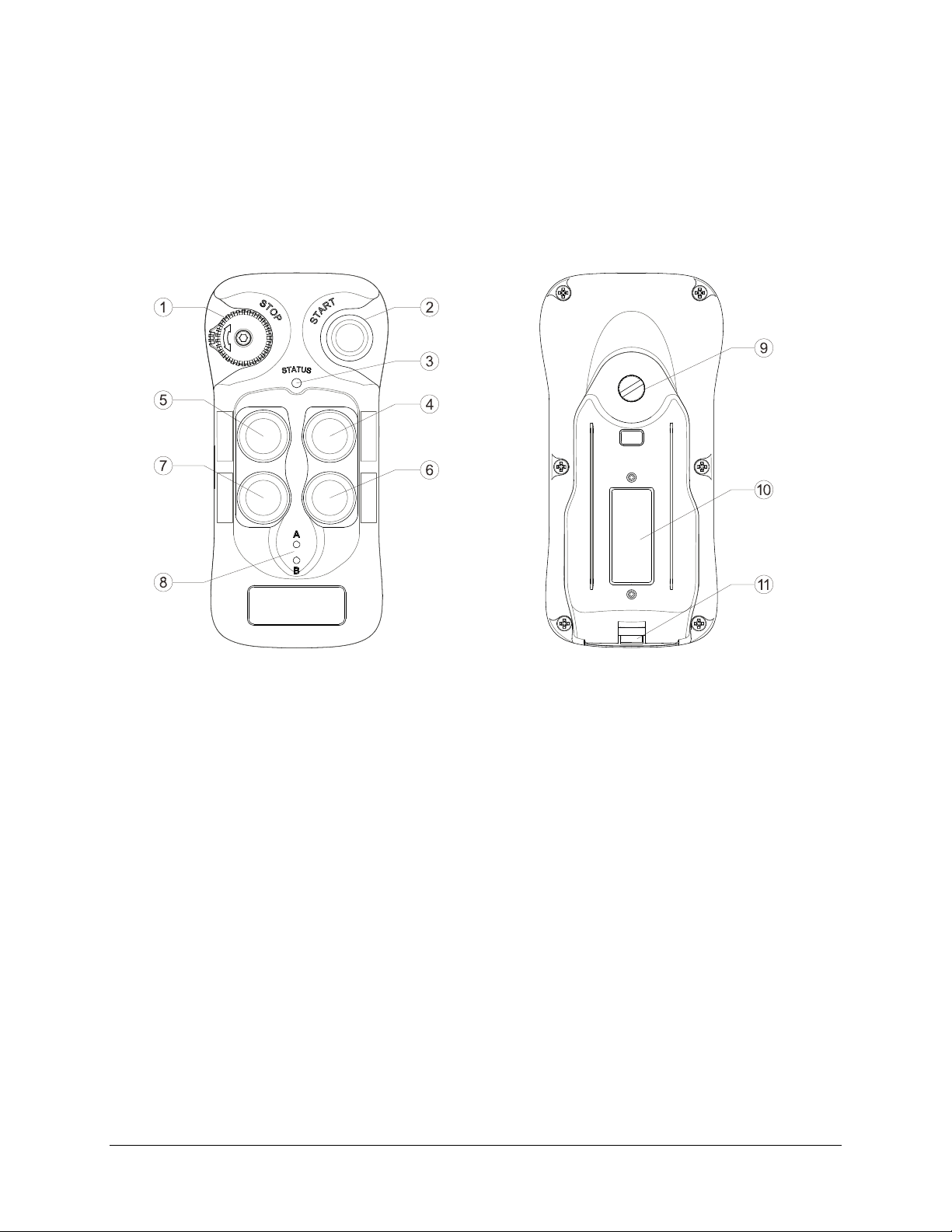
3 General System Information
3.1 Transmitter
3.1.1 External Illustration
1. STOP Button 7. Pushbutton 4 (PB4)
2. START Button 8. A/B LED Indicators
3. Status LED Indicator 9. Battery Cover Screw
4. Pushbutton 1 (PB1) 10. System Information
5. Pushbutton 2 (PB2) 11. Lanyard and Waist Belt Attachment Slot
6. Pushbutton 3 (PB3)
Flex 4Base® CE Instruction Manual
January 2017
Page 12 of 41
Page 13
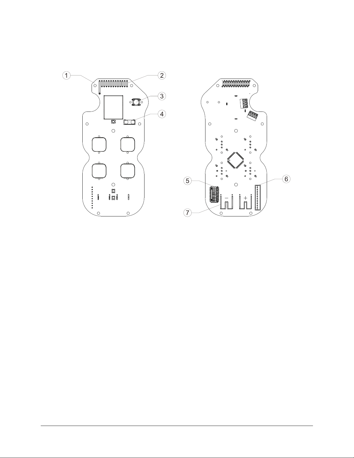
3.1.2 Internal Illustration
1. RF/Encoder Board 5. Function Dipswitch
2. Antenna 6. Programming Port
3. START Button 7. Battery Contacts
4. Infrared Sensors
Flex 4Base® CE Instruction Manual
January 2017
Page 13 of 41
Page 14
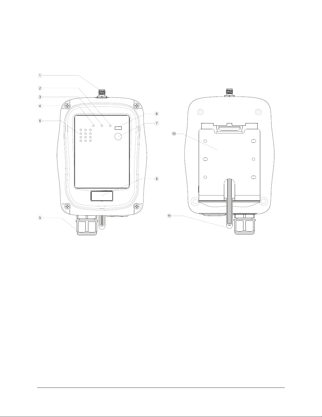
3.2 Receiver
3.2.1 External Illustration
1. External Antenna Port (optional) 7. Remote Pairing Button
2. COM LED Indicator 8. System Information
3. Status LED Indicator 9. Cord Grip
4. Power LED Indicator 10. Mounting Bracket
5. Output Relay LED Indicators 11. Mounting Bracket Release
6. Infrared Sensors
Flex 4Base® CE Instruction Manual
January 2017
Page 14 of 41
Page 15
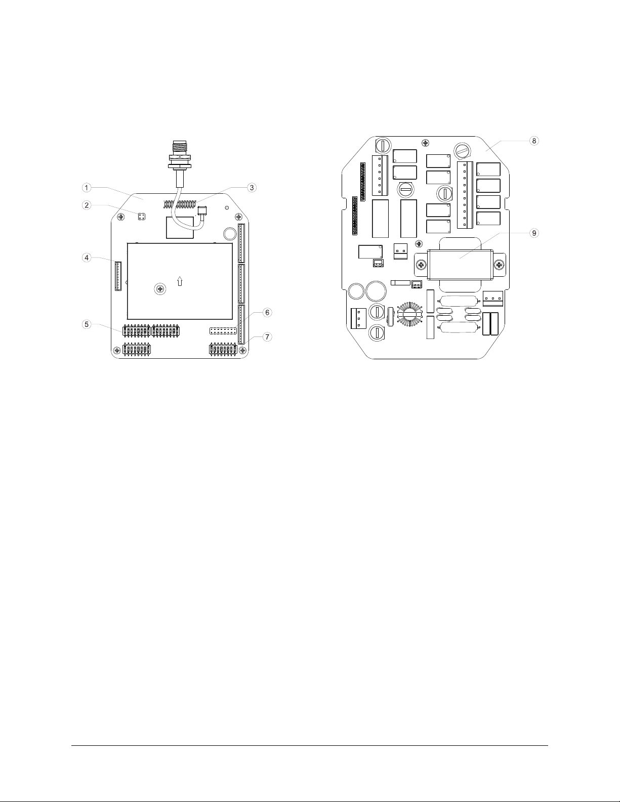
3.2.2 Internal Illustration
1. RF/Decoder Board 6. Function Jumpers
2. INT/EXT Antenna Jumpers 7. Channel Dipswitch
3. Internal Antenna 8. AC Line Filter/Relay Board
4. Programming Port 9. Power Transformer
5. Function Dipswitches
Flex 4Base® CE Instruction Manual
January 2017
Page 15 of 41
Page 16
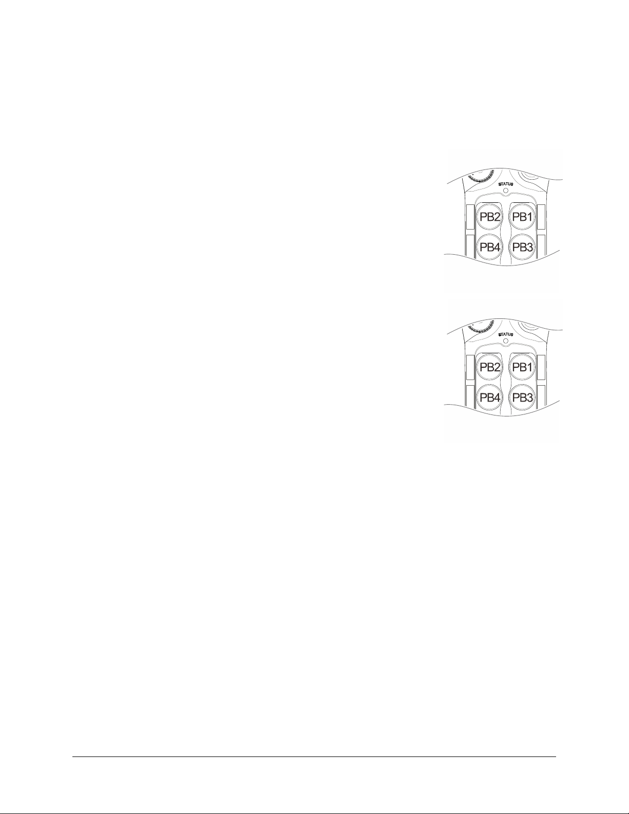
4.1 Transmitter
4.1.1 Transmitter Firmware Version
1. Press down the STOP button (transmitter power off).
2. Press and hold PB1 and PB3 at the same time.
3. Reset the STOP button by rotating it clockwise or counter-
clockwise; it will pop up (transmitter power on).
4. Release PB1 and PB3 at the same time. The Status LED will
display the firmware version with red, green and orange blinks.
5. Exit Firmware Version mode by pressing down the STOP button
(transmitter power off).
4.1.2 Transmitter Channel Settings
1. Press down the STOP button (transmitter power off).
2. Press and hold PB1 and PB2 at the same time.
3. Reset the STOP button by rotating it clockwise or counter-
clockwise; it will pop up (transmitter power on).
4. Release PB1 and PB2 at the same time. The Status LED displays
current channel setting with red and green blinks. A green blink
represents the tens (+10) and a red blink represents the units (+1).
For example, 1 green blink followed by 5 red blinks is channel 15.
5. Change the transmitter channel by pressing PB1 to increment the
units (+1) and PB2 to increment the tens (+10). For example, pressing PB2 two times and
then PB1 four times is channel 24 (Status LED blinks 2 greens and 4 reds).
6. Transfer the newly selected channel to the receiver by pressing and holding the START
button until the Status LED turns to constant green (transfer complete). Press down the
STOP button if constant green is not shown on the Status LED after more than 10 seconds
(transfer incomplete); the transmitter will revert back to its previous channel setting. Make
sure the receiver power is turned on and within the operating distance during the entire
process. Skip step 6 if changing the receiver channel is not required.
7. Exit Channel Setting mode by pressing down the STOP button (transmitter power off).
NOTE: When selecting a new channel, make sure each button press does not exceed 3 seconds
Step 6 illustrated above is strictly required if you intend to change the entire system channel (both
transmitter and receiver). The entire system no longer works if step 6 is skipped because the
transmitter and receiver channels are now different (new vs. old). In this case you would have to
redo steps 1 through 4 and step 6 to transfer the newly selected transmitter channel to the
receiver.
4 Function Settings
.
Important Note:
Flex 4Base® CE Instruction Manual
January 2017
Page 16 of 41
Page 17
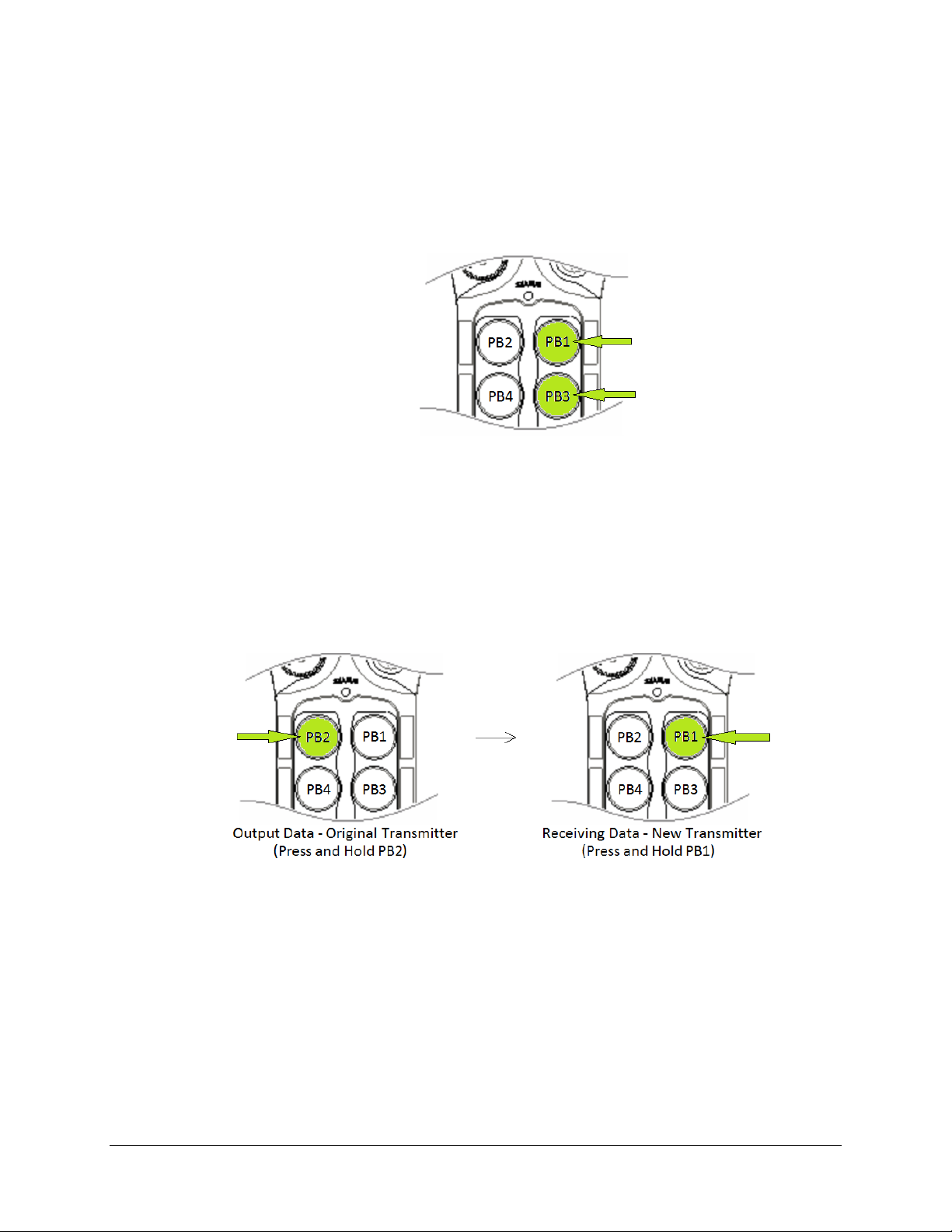
4.1.3 Remote Pairing
4.1.3.1 Transmitter-to-Transmitter Pairing
1. Obtain the original transmitter.
2. Press down the STOP button (transmitter power off).
3. Press and hold PB1 and PB3 at the same time.
4. Reset the STOP button by rotating it clockwise or counter-clockwise; it will pop up
(transmitter power on) – after a brief pause, let go of PB1 and PB3.
5. Repeat steps 2 through 4 for the new transmitter.
6. Now both the original transmitter and the new transmitter are in Remote Pairing Mode.
7. Simultaneously press and hold PB2 on the original transmitter (Status LED off and LED-B
constant red) and PB1 on the new transmitter (Status LED blinks green and LED-A
constant red).
8. When the Status LED (receiving data end) turns to constant green while both
pushbuttons are still pressed down, the pairing is completed.
9. Exit Remote Pairing mode by pressing down the STOP button on both transmitters.
NOTE: During remote pairing, make sure the distance between the two transmitters is within
1 meter.
Flex 4Base® CE Instruction Manual
January 2017
Page 17 of 41
Page 18
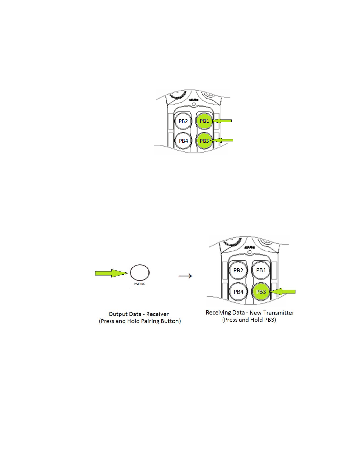
4.1.3.2 Receiver-to-Transmitter Pairing
1. Obtain the new transmitter.
2. Press down the STOP button (transmitter power off).
3. Press and hold PB1 and PB3 at the same time.
4. Reset the STOP button by rotating it clockwise or counter-clockwise; it will pop up
(transmitter power on) – after a brief pause, let go of PB1 and PB3.
5. Now the new transmitter is in Remote Pairing mode.
6. Ensure power is applied to the receiver.
7. Press and hold both the PAIRING button located on the receiver cover and hold PB3 on
the new transmitter at the same time. When the transmitter Status LED turns to constant
green while both pushbuttons are still pressed down, the pairing is completed.
8. Exit Remote Pairing mode by pressing down the STOP button (transmitter power off).
NOTE: Make sure the pairing process is executed within distance of 10 meters from one
another and no other active receivers nearby. During the pairing process, the
receiver MAIN relays must be deactivated (relay open).
Flex 4Base® CE Instruction Manual
January 2017
Page 18 of 41
Page 19
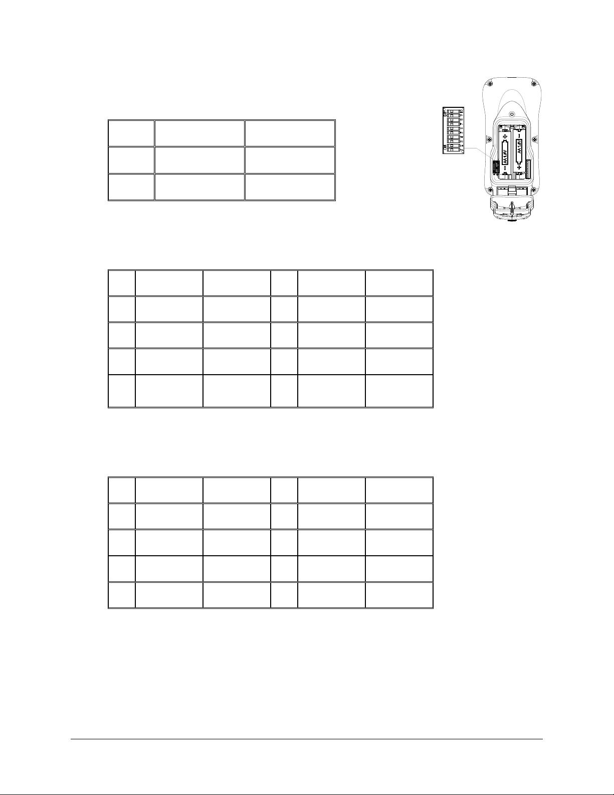
4.1.4 Transmitter Start Function Settings
When the transmitter goes into sleep mode, the system is temporarily
deactivated (MAIN relays opened). Press the START button or any
pushbutton to wake up the system (MAIN relays closed).
1
2
Dipswitch
Settings
xxxxxxxxx0
xxxxxxxxx1
Function
START
Reactivation
Any Button
Reactivation
4.1.5 Transmitter Inactivity Timer Settings
Set how long the transmitter enters the sleep mode when not in use (pushbutton not pressed).
When the transmitter goes into sleep mode the receiver MAIN relays are deactivated.
Dipswitch
Settings
Time
Dipswitch
Settings
Time
1
2
3
4
xxx000xxxx
xxx001xxxx
xxx010xxxx
xxx011xxxx
1 minute
20 seconds
3 minutes
5 minutes
5
6
7
8
xxx100xxxx
xxx101xxxx
xxx110xxxx
xxx111xxxx
10 minutes
30 minutes
60 minutes
Constant On
(sleep mode
disabled)
4.1.6 Transmitter Output Power Settings
1mW offers the shortest operating range with lowest battery consumption while 10mW offers the
longest operating range with highest battery consumption (manufacture preset at 5mW).
1
2
3
4
Dipswitch
Settings
000xxxxxxx
001xxxxxxx
010xxxxxxx
011xxxxxxx
Output
Power
1mW
2mW
3mW
4mW
5
6
7
8
Dipswitch
Settings
100xxxxxxx
101xxxxxxx
110xxxxxxx
111xxxxxxx
Output
Power
5mW
6mW
8mW
10mW
Flex 4Base® CE Instruction Manual
January 2017
Page 19 of 41
Page 20
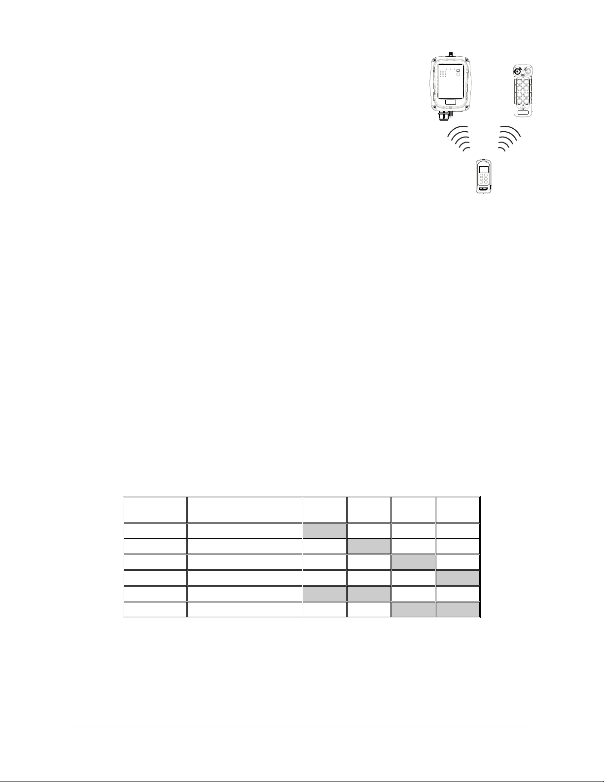
4.1.7 Infrared Programming
Other custom functions and settings not listed in this manual can be
programmed via the infrared IR programmer unit, such as the system
serial number, frequency range, new and updated functions, plus many
others. Please contact a Magnetek representative for more details.
4.1.8 Pushbutton Function Settings
1. Press down the STOP button (transmitter power off).
2. Press and hold PB3 and PB4 at the same time.
3. Reset the STOP button by rotating it clockwise or counter-clockwise;
it will pop up (transmitter power on).
4. Release PB3 and PB4 at the same time (entered Pushbutton Function mode).
5. The Status LED displays current pushbutton function setting with orange, green and red blinks.
An orange blink represents the hundreds (+100), a green blink represents the tens (+010), and
a red blink represents the units (+001). For example, one orange blink followed by two green
blinks and five red blinks is pushbutton function number 125. Pushbutton function number with
“0” is represented by no orange, green or red blink. For example, one orange blink followed by
five red blinks is pushbutton function number 105.
6. Set the pushbutton function number by pressing PB3 to increment the hundreds (+100), PB2 to
increment the tens (+010), PB1 to increment the units (+001), and PB4 to reset (000 - constant
orange). For example, pressing PB3 one time, PB2 four times, and PB1 six times is pushbutton
function number 146 (Status LED blinks 1 orange, 4 greens and 6 reds).
7. Exit Pushbutton Function mode by pressing down the STOP button (transmitter power off).
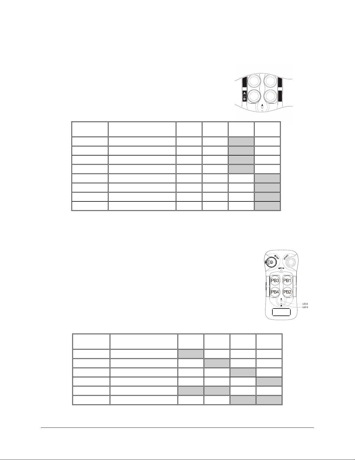
4.1.8.1 Toggled Pushbutton with LED Indication – Standard Right/Left
Pushbutton Configuration
Set pushbutton toggled function (latching output relay) with LED indications. LED A and LED
B, shown inside the shaded box, illustrates which LED on the transmitter lights up when the
designated pushbutton is pressed.
Function
Number
1
2
3
4
13
14
* PB1…PB4 → Pushbutton number.
* Normal → Normal momentary contact.
* A/1&2 ~ D/1&2 → A/B pushbutton select function with designated LED indication.
Display Type PB1 PB2 PB3 PB4
1 Red LED A Normal Normal Normal
2 Reds Normal LED B Normal Normal
3 Reds Normal Normal LED A Normal
4 Reds Normal Normal Normal LED B
1 Green + 3 Reds LED A LED B Normal Normal
1 Green + 4 Reds Normal Normal LED A LED B
Flex 4Base® CE Instruction Manual
January 2017
Page 20 of 41
Page 21
4.1.8.2 A/B Pushbutton Select with LED Indication – Standard Right/Left
Pushbutton Configuration
There are four different types of A/B selector sequences available. Choose one that is most
suitable for your application. Refer to Section 6.1: Output Relay Contact Diagrams.
Type-A selector sequence: A → B
Type-B selector sequence: Off → A → B
Type-C selector sequence: A → B → A+B
Type-D selector sequence: Off → A → B → A+B
Function
Number
25
26
27
28
29
30
31
32
* PB1…PB4 → Pushbutton number.
* Normal → Normal momentary contact.
* A/1&2 ~ D/1&2 → A/B pushbutton select function with designated LED indication.
Display Type PB1 PB2 PB3 PB4
2 Greens + 5 Reds Normal Normal A/1&2 Normal
2 Greens + 6 Reds Normal Normal B/1&2 Normal
2 Greens + 7 Reds Normal Normal C/1&2 Normal
2 Greens + 8 Reds Normal Normal D/1&2 Normal
2 Greens + 9 Reds Normal Normal Normal A/1&2
3 Greens Normal Normal Normal B/1&2
3 Greens + 1 Reds Normal Normal Normal C/1&2
3 Greens + 2 Reds Normal Normal Normal D/1&2
4.1.8.3 Toggled Pushbutton with LED Indication – Inline Top/Bottom
Pushbutton Configuration
Set pushbutton toggled function (latching output relay) with LED
indications. LED A and LED B shown inside the shaded box illustrates
which LED on the transmitter lights up when the designated pushbutton
is pressed. Refer to Section 4.2.4: Jumper SettingsError! Reference
source not found..
Function
Number
1
3
2
4
19
22
* PB1…PB4 → Pushbutton number.
* Normal → Normal momentary contact.
* LED A & LED B → Pushbutton toggled function with designated LED indication.
Display Type PB1 PB2 PB3 PB4
1 Red LED A Normal Normal Normal
3 Reds Normal LED B Normal Normal
2 Reds Normal Normal LED A Normal
4 Reds Normal Normal Normal LED B
1 Green + 9 Reds LED A LED B Normal Normal
2 Greens + 2 Reds Normal Normal LED A LED B
Flex 4Base® CE Instruction Manual
January 2017
Page 21 of 41
Page 22
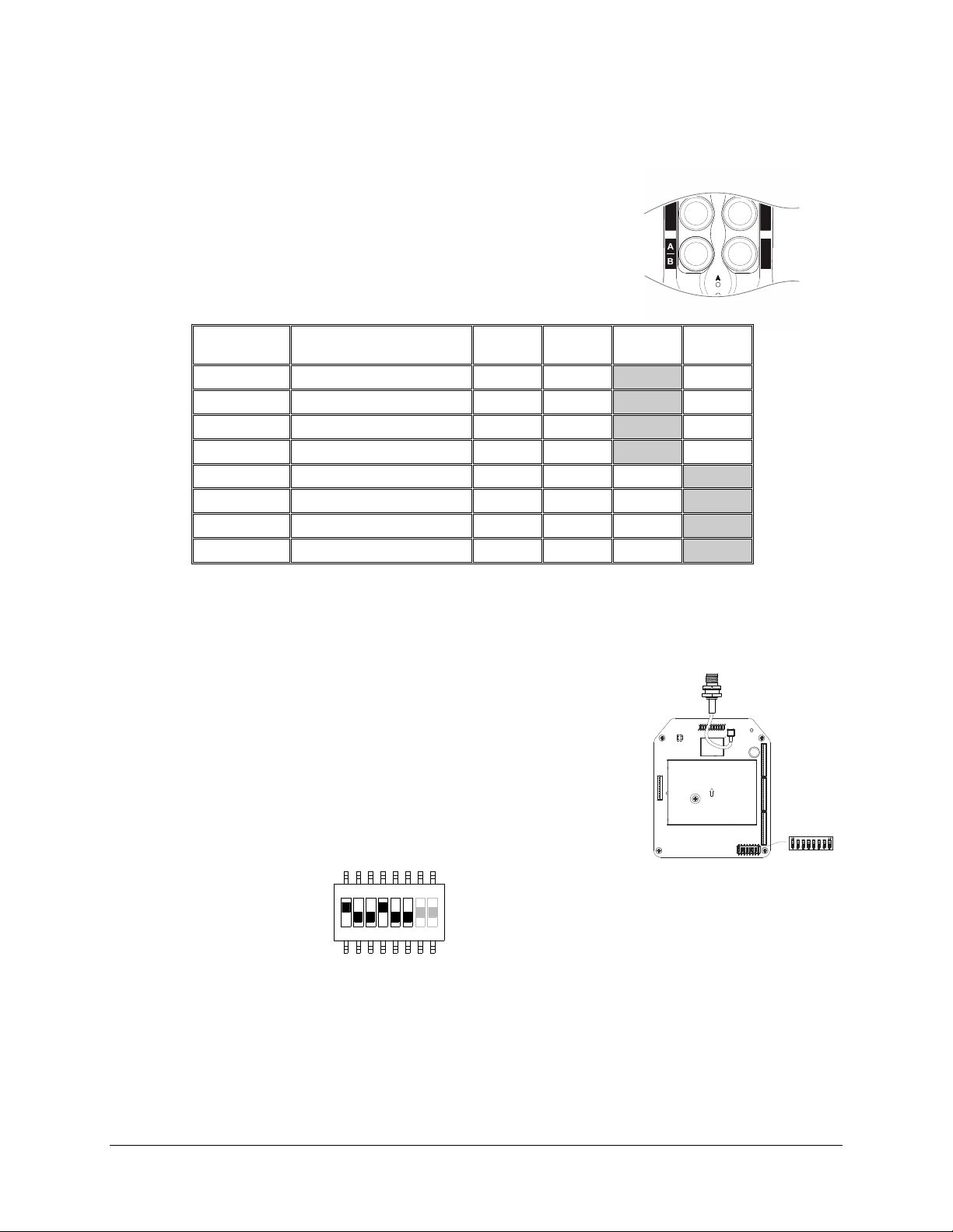
4.1.8.4 A/B Pushbutton Select with LED Indication – Inline Top/Bottom
Pushbutton Configuration
There are four different types of A/B selector sequences available. Choose one that is most
suitable for your application. Refer to Section 4.2.4: Jumper SettingsError! Reference
source not found. and Section 6.1: Output Relay Contact Diagrams.
Type-A selector sequence: A → B
Type-B selector sequence: Off → A → B
Type-C selector sequence: A → B → A+B
Type-D selector sequence: Off → A → B → A+B
Function
Number
49
50
51
52
29
30
31
32
* PB1…PB4 → Pushbutton number.
* Normal → Normal momentary contact.
* A/1&2 ~ D/1&2 → A/B pushbutton select function with designated LED indication.
Display Type PB1 PB2 PB3 PB4
4 Greens + 9 Reds Normal Normal A/1&2 Normal
5 Greens Normal Normal B/1&2 Normal
5 Greens + 1 Reds Normal Normal C/1&2 Normal
5 Greens + 2 Reds Normal Normal D/1&2 Normal
2 Greens + 9 Reds Normal Normal Normal A/1&2
3 Greens Normal Normal Normal B/1&2
3 Greens + 1 Reds Normal Normal Normal C/1&2
3 Greens + 2 Reds Normal Normal Normal D/1&2
4.2 Receiver
4.2.1 Receiver Channel Settings
Set the receiver channel by configuring the channel dipswitch
located on the RF/decoder board; only the first six dip positions are
used for channel programming. The system channels table on
Section 5 illustrates which dipswitch setting corresponds to which
channel. Once the receiver channel is altered make sure to change
the transmitter channel as well. The channel on both the transmitter
and receiver must be identical in order for the system to work (refer
to Section 4.1.2: Transmitter Channel Settings).
Example:
Bottom position → “0”
71 423 56 8
NOTE: The above dipswitch setting “1 0 0 1 0 0” corresponds to “channel 36” in the system
channels table on Section 5.
Top position → “1”
Flex 4Base® CE Instruction Manual
January 2017
Page 22 of 41
Page 23
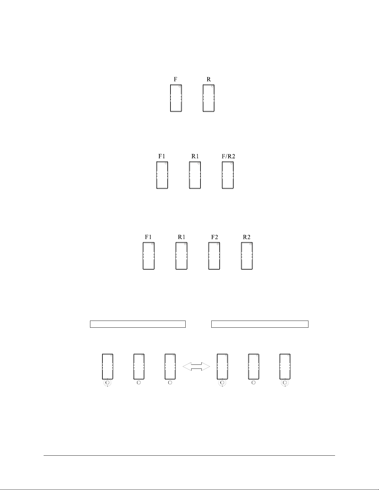
4.2.2 Output Relay Configurations
4.2.2.1 Output Relay Types
1. 2 output relays per motion – single speed only
Output relays with Forward (F) and Reverse (R) 1st speed only.
2. 3 output relays per motion – shared 2
Output relays with Forward 1st speed (F1), Reverse 1st speed (R1) and Forward/Reverse 2nd speed
(F/R2). Forward and Reverse 2
nd
speed (F/R2) shared the same output relay.
3. 4 output relays per motion – separate 1
Output relays with Forward 1st speed (F1), Reverse 1st speed (R1), Forward 2
Reverse 2
nd
speed (R2). Forward and Reverse 2nd speed are separate output relays.
4.2.2.2 Output Relay Actions at 2nd Speed
1. 3 output relays configuration with Closed/Closed contact at 2nd speed
F1 (or R1) output relay closed at 1st speed and F1 + F/R2 (or R1 + F/R2) output relays closed
nd
at 2
speed. Refer to Section 4.2.3.1 on how to set to this function.
Forward 1st speed pushbutton pressed Forward 2nd speed pushbutton pressed
↓ ↓
F1 F/R2R1 R1F1 F/R2
nd
speed output relay
st
and 2nd speed output relays
nd
speed (F2) and
Flex 4Base® CE Instruction Manual
January 2017
Page 23 of 41
Page 24
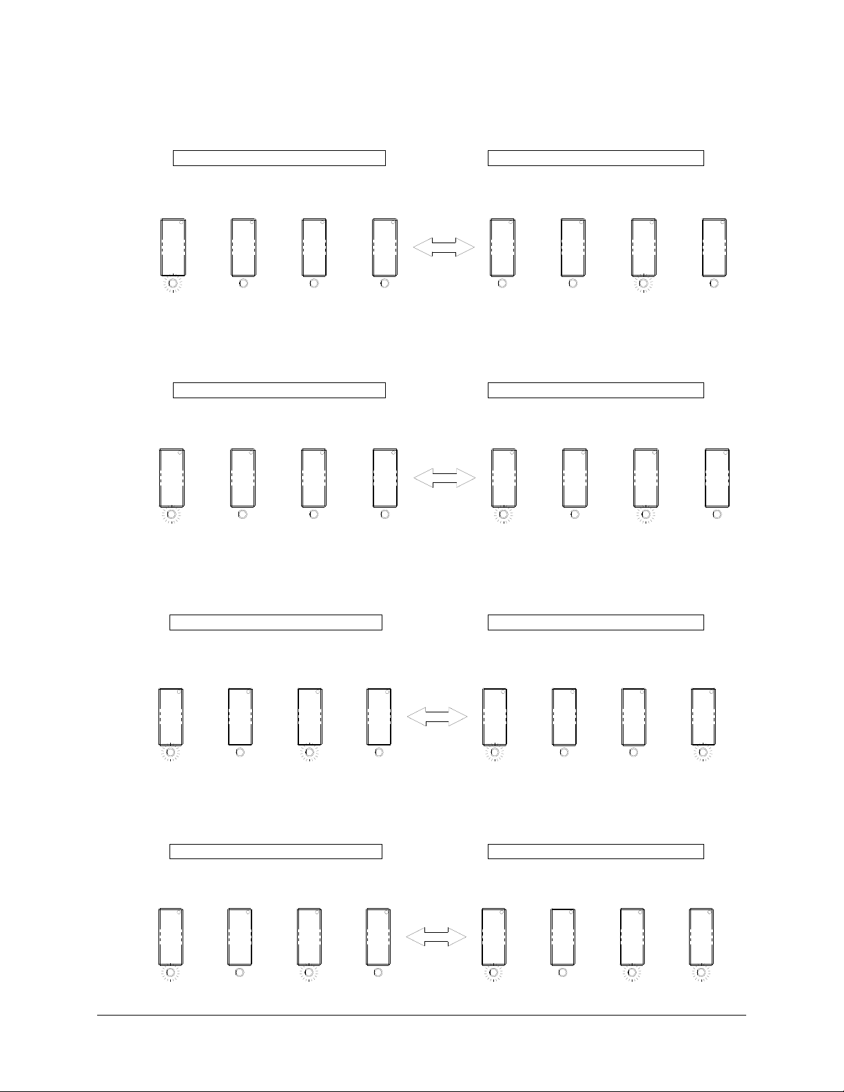
2. 4 output relays configuration with Opened/Closed contact at 2
F1 (or R1) output relay closed at 1st speed and F2 (or R2) output relay closed at 2nd speed. Refer
to Section 4.2.3.1 on how to set to this function.
nd
speed
Forward 1st speed pushbutton pressed Forward 2nd speed pushbutton pressed
↓ ↓
R2F2R1F1 R2F2R1F1
3. 4 output relays configuration with Closed/Closed contact at 2
F1 (or R1) output relay closed at 1st speed and F1 + F2 (or R1 + R2) output relays closed at 2nd
speed. Refer to Section 4.2.3.1 on how to set to this function.
nd
speed
Forward 1st speed pushbutton pressed Forward 2nd speed pushbutton pressed
↓ ↓
F1 R1 F2 R2R2F2R1F1
4. 4 output relays configuration with Slow and Fast output relays (Type A)
Fwd (or Rev) + Slow output relays closed at 1st speed and Fwd (or Rev) + Fast output relays closed at
nd
speed. Refer to Section 4.2.3.1 on how to set to this function.
2
Forward 1st speed pushbutton pressed Forward 2nd speed pushbutton pressed
↓ ↓
Slow
Fast
Fwd Rev
Slow
FastFwd Rev
5. 4 output relays configuration with Slow and Fast output relays (Type B)
Fwd + Slow (or Rev + Slow) output relays closed at 1st speed and Fwd + Slow + Fast (or Rev + Slow +
Fast) output relays closed at 2
nd
speed. Refer to Section 4.2.3.1 on how to set to this function.
Forward 1st speed pushbutton pressed Forward 2nd speed pushbutton pressed
↓ ↓
Fwd Rev
Slow
Fast Fwd Rev
Slow
Fast
Flex 4Base® CE Instruction Manual
January 2017
Page 24 of 41
Page 25
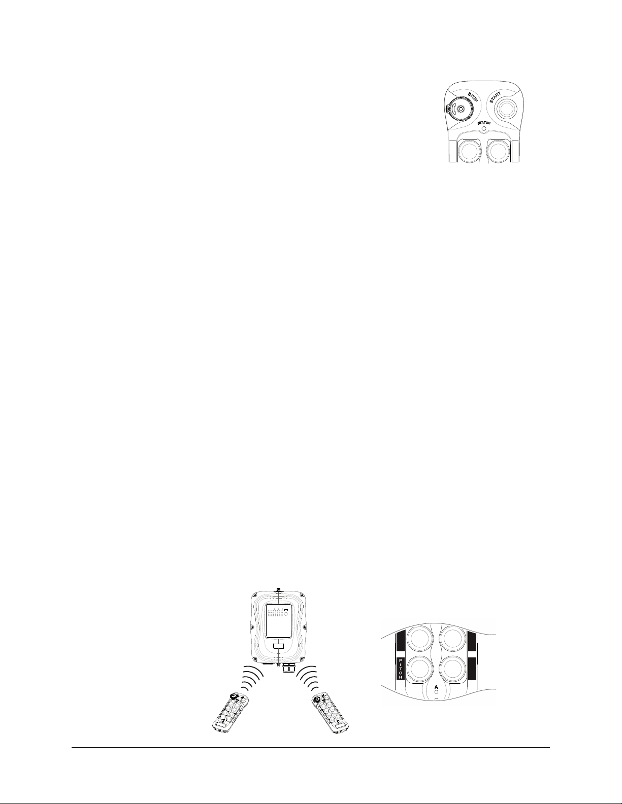
4.2.2.3 START + AUX Function
After initiating the START function at transmitter startup, the same
START button becomes an auxiliary function with momentary
contact connected through the K30 Function output relay. There are
other types of auxiliary functions made available for K25, K26, and
K30 Function output relays (refer to Section 4.2.7). Please contact
a Magnetek representative if your application requires other types of
auxiliary functions connected to these Function output relays.
4.2.2.4 ON/OFF Pushbutton Function
The user can set any of the two adjacent pushbuttons on the transmitter to behave like a
mechanical ON & OFF rocker or toggle switch. ON output relay closes when ON pushbutton
is pressed (OFF output relay opens) and OFF output relay closes when OFF pushbutton is
pressed (ON output relay opens). Refer to Section 4.2.3.1 on how to set to this function.
4.2.2.5 Brake Function
When the transmitter pushbutton is released from 2nd speed up to 1st speed, both 1st and 2nd
speed output relays will open for up to 1 second and then with 1
thereafter. Refer to Section 4.2.3.1 on how to set to this function.
st
speed output relay closed
4.2.2.6 External Warning Function
The user can install an external warning device (rotating lights, horn, etc.) to the K26 Function
output relay located inside the receiver. The user can choose which pushbutton pair (or pairs)
triggers the external warning device when pressed. Refer to Section 4.2.3.1 on how to set to
this function.
4.2.2.7 Momentary Contact
When the pushbutton is released, the corresponding output relay will open or deactivate.
This type of relay action usually applies to external applications such as horns and buzzers.
Refer to Section 4.2.3.2 on how to set to this function.
4.2.2.8 Toggled Contact
When the pushbutton is released, the corresponding output relay will maintain contact or
closure until next time the user presses the same pushbutton again. This type of relay action
usually applies to external applications such as lights. Refer to Section 4.2.3.2 on how to set
this function.
4.2.2.9 Pitch & Catch Function
This function allows two operators to control one crane from opposite ends of a cross or long
travel. When set to “Pitch & Catch” make sure the second transmitter is set to the next upper
channel (channel X+1). For example, if the system is set to channel 01, then the newly added
second transmitter must be set to channel 02 and with an identical serial number.
Furthermore, the channel dipswitch position #7 and #8 on the RF/decoding board must set to
“10” for 2-channel scanning (scans channel 01 and 02). Refer to Sections 4.2.2.10 and
4.2.3.2 on how to set to this function.
Flex 4Base® CE Instruction Manual
January 2017
Page 25 of 41
Page 26
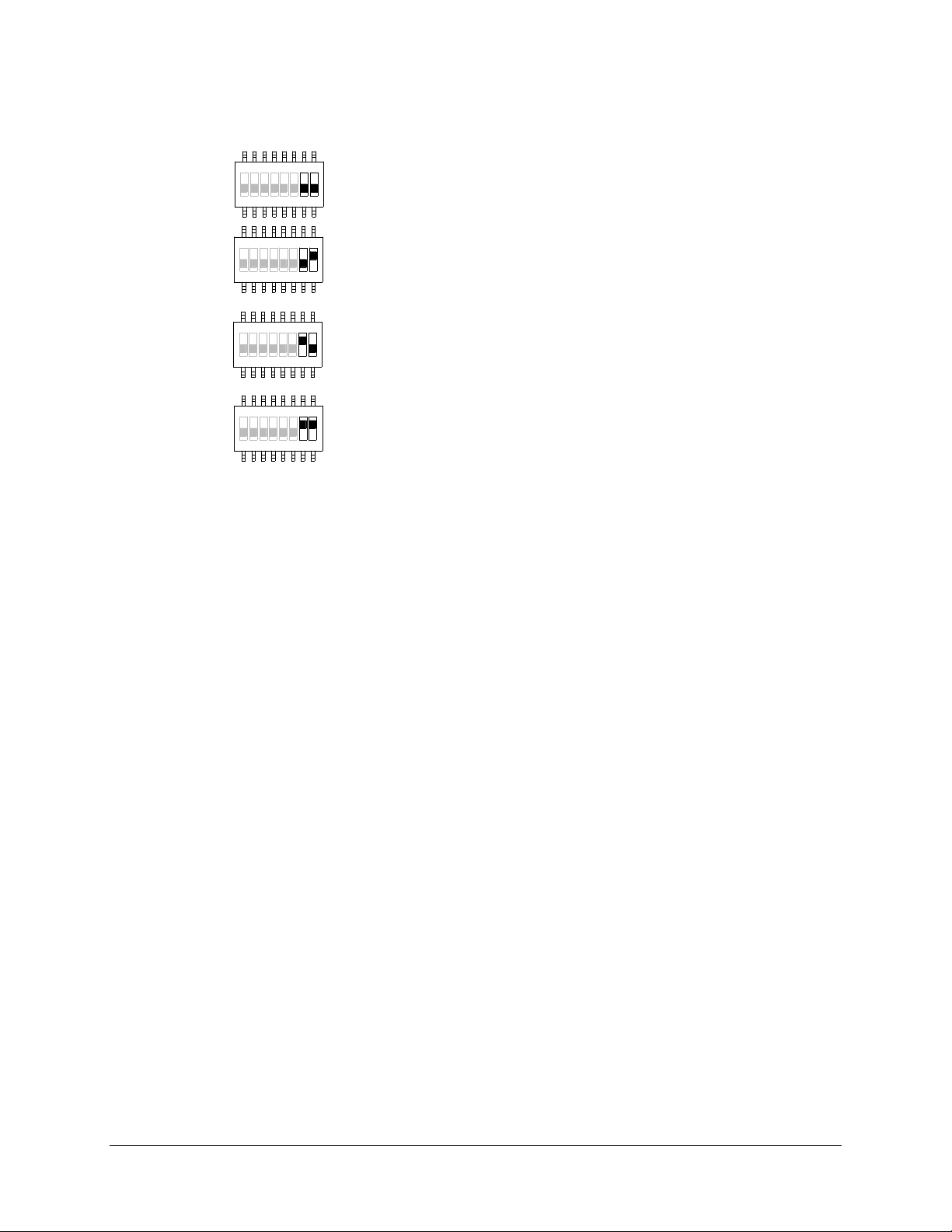
4.2.2.10 Receiver Channel Scanning Function
(1) → “00” manufacture preset (channel X)
(2) → “01” scans 2 channels (channel X and channel X+1)
(3) → “10” scans 3 channels (channel X… channel X+2)
(4) → “11” scans 4 channels (channel X… channel X+3)
Example: If the first six dipswitch positions are set to channel 01 (000001), when set to 2-
41 32 65 87
4132 65 87
4231 7856
41 2 3 65 78
* Channel X → channel set on the Channel dipswitch
channel scanning (type-2 above) the receiver will only scan channel 01 and 02.
Flex 4Base® CE Instruction Manual
January 2017
Page 26 of 41
Page 27
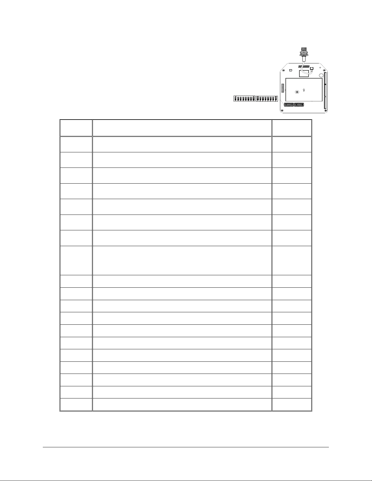
4.2.3 Dipswitch Settings
4.2.3.1 Interlocked Pushbutton Pair
Interlocked means any pushbutton pair cannot be
pressed simultaneously, as that pair will cancel the other
pair out. Interlocked setting usually applies to an
electric motor’s forward and reverse motion and On/Off
switches. Each dipswitch on the RF/decoder board
corresponds to a pushbutton pair.
Dip
Settings
Function Descriptions
# of Relays
Used
00000000
00000010
00000100
00000110
00001000
00001010
00001100
00010010
00010100
00100000
00100010
00100100
Single speed only
4 output relays Closed/Closed relay action at 2nd speed
(separate 2
3 output relays Closed/Closed relay action at 2nd speed
(shared 2
4 output relays Opened/Closed relay action at 2nd speed
(separate 2
Forward (or Reverse) + Fast output relays engaged at 2nd speed
Forward (or Reverse) + Slow + Fast output relays engaged at 2nd
On (right button) & Off (left button)
On + Start/Off + Start - For added safety, you must first
press and hold the START button and then press the
On or Off pushbutton to activate the output relay.
FWD/REV toggled (latching)
Single speed + External warning*
4 output relays Closed/Closed relay action + External warning*
3 output relays Closed/Closed relay action + External warning*
nd
speed output relays)
nd
speed output relay)
nd
speed output relays)
speed
2
4
3
4
4
4
2
2
2
2
4
3
00100110
01000010
01000100
01000110
01100010
01100100
01100110
* External warning function requires installing an external warning device such as a horn and lights to the K26
Function output relay.
4 output relays Opened/Closed relay action + External warning*
4 output relays Closed/Closed relay action + Brake
3 output relays Closed/Closed relay action + Brake
4 output relays Opened/Closed relay action + Brake
4 output relays Closed/Closed relay action + Brake + External warning*
3 output relays Closed/Closed relay action + Brake + External warning*
4 output relays Opened/Closed relay action + Brake + External warning*
Flex 4Base® CE Instruction Manual
4
4
3
4
4
3
4
January 2017
Page 27 of 41
Page 28
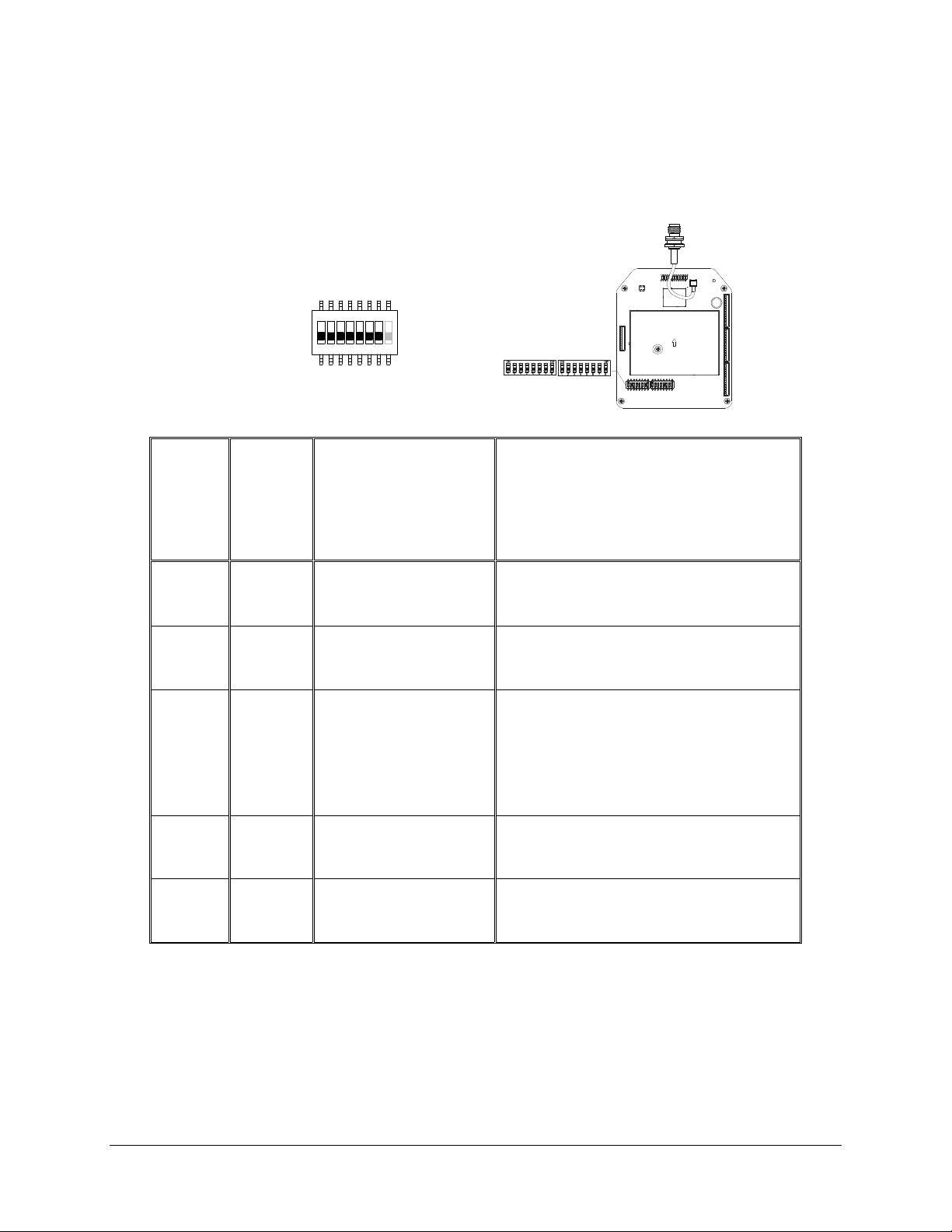
4.2.3.2 Non-Interlocked Pushbutton Pair
Non-interlocked setting allows the pushbutton pair(s) be pressed simultaneously. It usually
applies to the equipment’s auxiliary functions such as lights, horns, or buzzers. Each
dipswitch on the RF/decoder board corresponds to a pushbutton pair. Only the first seven
dipswitch positions are used (counting from left to right); the eighth dipswitch position (far
right) is not used.
1 324 756 8
Function
Code
A
B
C
D
E
Dip
Position
#1
1 000
1 001
1 100
1 110
1 111
Dip Position
#2 ~ #4 (left button)
&
#5 ~ #7 (right button)
Function Description
Normal (momentary) contact
Toggled (latching) contact
Normal + Start function - For added
safety, you must first press and hold the
START button and then press the
intended pushbutton to activate the
output relay.
Pitch & Catch
2 steps with Closed/Closed relay action
Example #1: Left button (set to function code A) / right button (set to function code B) → 1 000 001
Example #2: Left button (set to function code C) / right button (set to function code D) → 1 100 110
Flex 4Base® CE Instruction Manual
January 2017
Page 28 of 41
Page 29
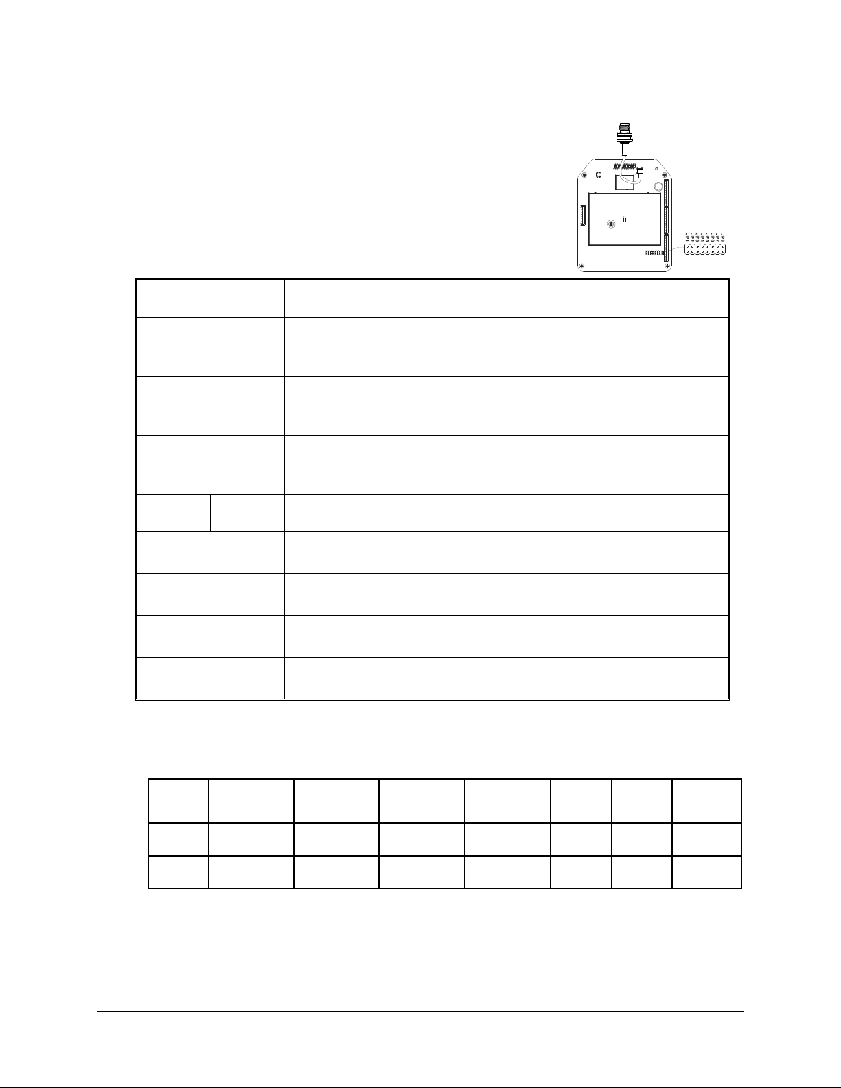
4.2.4 Jumper Settings
Jumper setting applies to functions such as the standard or reversed logic A/B selector
sequence, cable-free configurations, transmitter inline pushbutton
configurations, firmware version, system testing and remote pairing
methods.
Jumper Settings Function
JP2
(Inserted)
JP3
(Opened)
JP3
(Inserted)
JP4
(Inserted)
(Inserted)
(Inserted)
(Opened)
(Inserted)
JP5
(Inserted)
JP6
JP7
JP8
JP8
Pressing the START button is required when receiver MAIN relays
are deactivated (cancels ANY button setting on Section 4.1.4).
Standard A/B selector sequence - Output
relay A activated at A position, output relay B activated at B position,
both relays activated at A+B position.
Reversed logic A/B selector sequence - Output
relay B activated at A position, output relay A activated at B position,
both relays deactivated at A+B position.
Inline top/bottom pushbutton configuration for PB1 to PB4
Display system firmware version
For system testing only (receiver MAIN relays disabled)
Receiver-to-transmitter remote pairing
(pressing the Pairing button required)
Receiver-to-transmitter remote pairing
(pressing the Pairing button not required)
4.2.5 Fuse Ratings
FUSE # 110~120VAC 220~240VAC 380~400VAC 410~460VAC 24VAC
F3 ~ F10
F1 ~ F2
5.0A 5.0A 5.0A 5.0A 5.0A 5.0A 5.0A
0.5A 0.5A 0.5A 0.5A 1.0A 1.0A 2.0A
Flex 4Base® CE Instruction Manual
42 &
48VAC
9~36VDC
January 2017
Page 29 of 41
Page 30
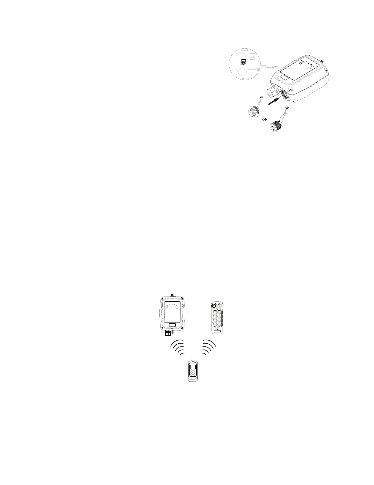
4.2.6 Lights Indicator and Buzzer Installation
The miniature lights indicator and buzzer can be easily
fitted onto the receiver enclosure. If the buzzer is installed
it will sound for up to 3 seconds when the START button is
initially pressed (manufacture preset to HORN function).
The same START button becomes a momentary output
thereafter. When the receiver MAIN relays are activated,
the buzzer is also activated. Make sure the buzzer is
connected to the K30 Function output relay CN11 port
located on the AC line filter/relay board inside the receiver.
The indicator light should be wired into K25. This function
relay is preset so that the indicator light will remain active anytime the MAIN relays are active as
well. Please contact a Magnetek representative if you would like the lights indicator or the buzzer
to work differently than described above.
4.2.7 Other Function Output Relays Settings
Listed below are other types of functions that can be outputted through the two Function output
relays (K25 and K26) via the infrared IR programmer unit. Please contact a Magnetek representative
for more details.
LV → Function relay closes when receiver voltage is low.
ID → Function relay works simultaneously with all motion commands.
NORMAL → START function + AUX with normal momentary output.
TOGGGLE → START function + AUX with toggled/latching output.
EXT → Function relay works simultaneously with the receiver MAIN relays.
TDM A+B → Function relay closes when selector switch is rotated to the A+B position and opens
when rotate to A or B positions (tandem monitoring output).
HORN → Function relay closes for up to 3 seconds when START command is initiated at transmitter
power on and then becomes a normal momentary output thereafter.
Flex 4Base® CE Instruction Manual
January 2017
Page 30 of 41
Page 31

5 System Channels Table
Channel
01
02
03
04
05
06
07
08
09
10
11
12
13
14
Dipswitch Setting
000001
000010
000011
000100
000101
000110
000111
001000
001001
001010
001011
001100
001101
001110
Channel
32
33
34
35
36
37
38
39
40
41
42
43
44
45
Dipswitch Setting
100000
100001
100010
100011
100100
100101
100110
100111
101000
101001
101010
101011
101100
101101
15
16
17
18
19
20
21
22
23
24
25
26
27
28
29
30
001111
010000
010001
010010
010011
010100
010101
010110
010111
011000
011001
011010
011011
011100
011101
011110
46
47
48
49
50
51
52
53
54
55
56
57
58
59
60
61
101110
101111
110000
110001
110010
1100 11
110100
110101
110110
110111
111000
111001
111010
1110 11
11110 0
11110 1
31
011111
62
111110
Flex 4Base® CE Instruction Manual
January 2017
Page 31 of 41
Page 32
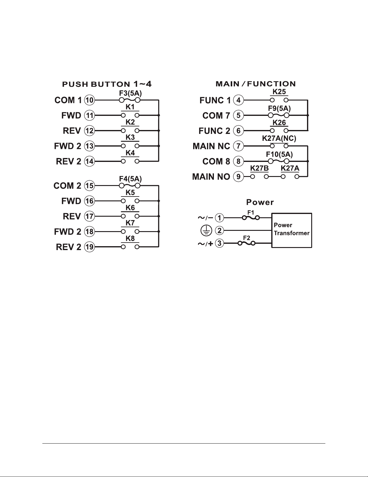
6 Receiver Installation
6.1 Output Relay Contact Diagrams
* For 9~36VDC power supply, wire #1 corresponds to the negative charge (-) and wire #3 corresponds to the
positive charge (+). Wire #2 is GROUND.
* If PB3 (or PB4) is set to A/B pushbutton select function, connect output A to K5 (or K6) and output B to K7 (or
K8). Refer to Section 4.1.8.2 on how to set to this function.
6.2 Pre-installation Precautions
1. Make sure the transmitter and receiver have identical serial numbers and channels.
2. Make sure the receiver is not set to the same channel as any other systems in use in the
surrounding area.
3. Make sure the crane or equipment is working properly prior to installation.
4. Make sure the power source to the receiver is set correctly.
5. Switch off the main power source to the crane or equipment prior to installation.
Flex 4Base® CE Instruction Manual
January 2017
Page 32 of 41
Page 33
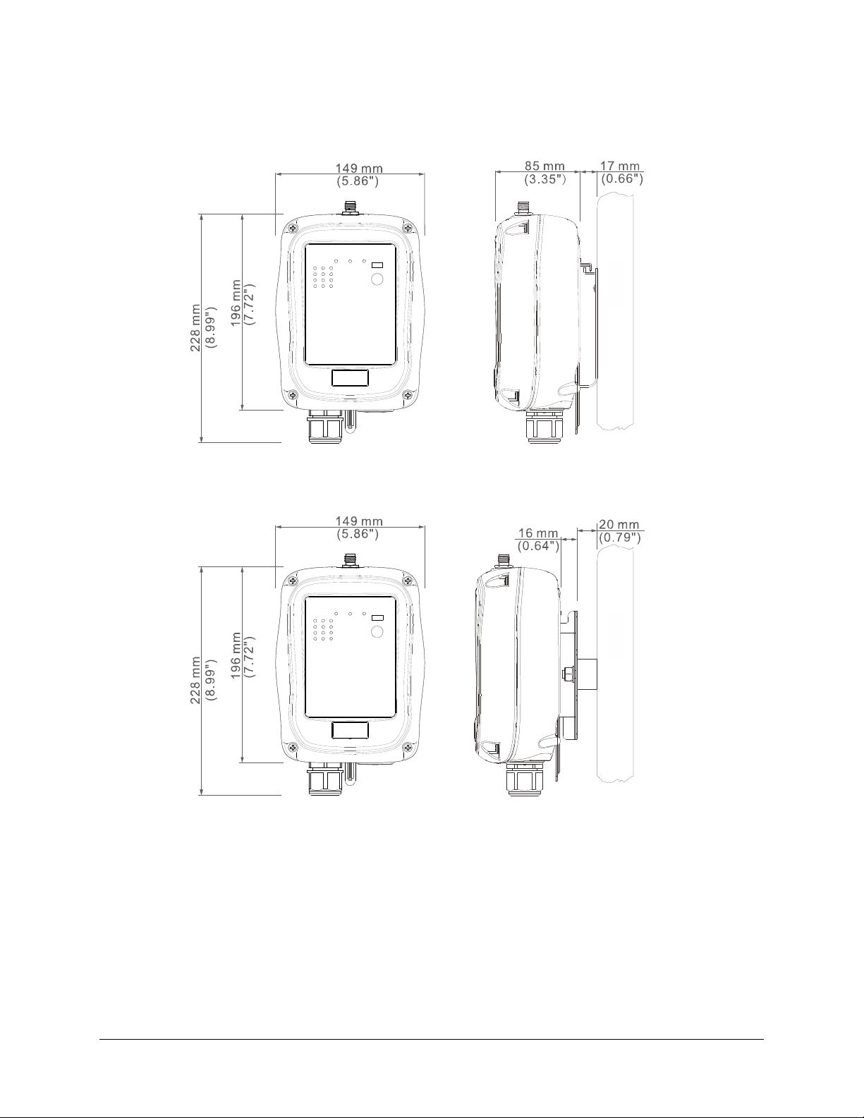
6.3 Step-By-Step Installation
Mounting Bracket Type 1
Mounting Bracket Type 2
Flex 4Base® CE Instruction Manual
January 2017
Page 33 of 41
Page 34
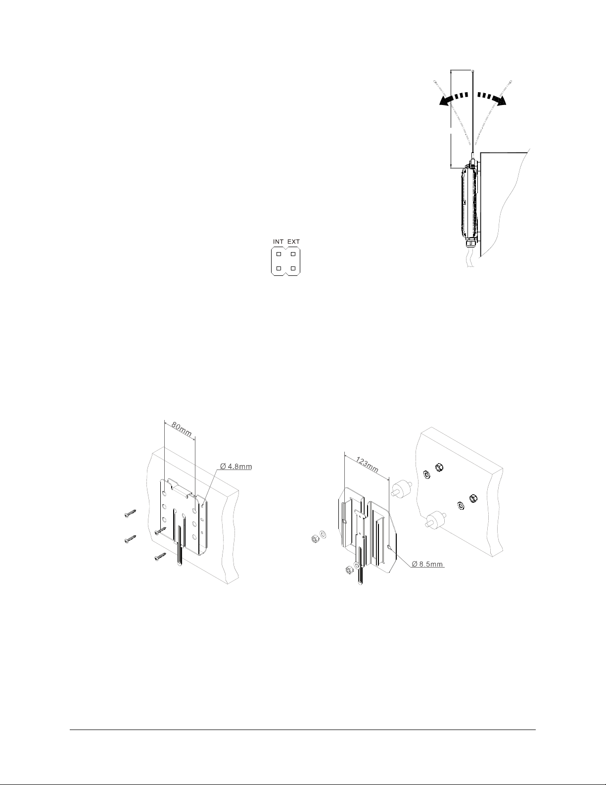
1. For best reception the location of the receiver should be visible to the
operator at all time.
2. The location selected should not be exposed to high levels of electric
noise. Mounting the receiver next to an unshielded variable frequency
drive may cause radio interference. Always locate the receiver as far
432 mm
away from variable frequency drives and electric motors as possible.
3. Ensure the selected location has adequate space to accommodate the
receiver. If an external antenna is used, to avoid the possibility of
antenna damage, always locate the receiver where the antenna is free
Control
Panel
from any obstacles.
4. When installing an external antenna make sure the MCX jack located
on the RF/decoder board inside the receiver is connected and jumper
set to “EXT” position.
5. For better reception, make sure the receiver is in an upright position.
6. Drill four holes for mounting bracket type 1 and two holes for mounting bracket type 2 on the
control panel, wall, or location where the receiver is to be installed.
7. Make sure the screws, bolts, or shock absorbers are tightened after installation (not provided with
the system).
Mounting Bracket Type 1 Mounting Bracket Type 2
8. Slide down the receiver along the guided track to secure the receiver to the mounting bracket.
9. Remove the receiver by pressing down the bracket release and pull the receiver upward until
it clears the guided track.
Flex 4Base® CE Instruction Manual
January 2017
Page 34 of 41
Page 35
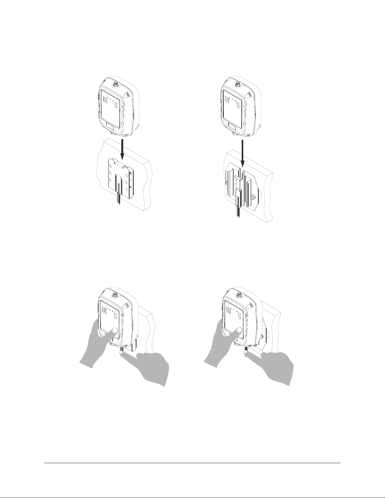
Install
Mounting Bracket Type 1 Mounting Bracket Type 2
Remove
Mounting Bracket Type 1 Mounting Bracket Type 2
Flex 4Base® CE Instruction Manual
January 2017
Page 35 of 41
Page 36
7 Operating Procedures
7.1 General Operation
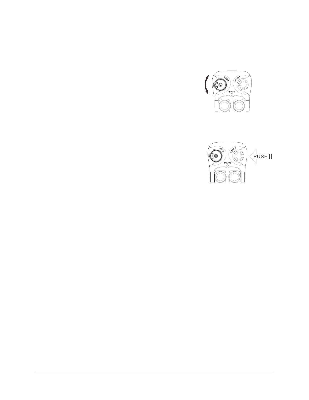
a) Reset the STOP button located on the top left hand corner of the transmitter by rotating
it clockwise or counter clockwise; the button will pop up. The
transmitter is powered on when the STOP button is elevated.
b) After turning on the transmitter power, check the Status LED on
the transmitter for any sign of system irregularities (refer to Section
7.5.1: Transmitter Status Indications). If the transmitter is in good
working order, the Status LED will blink green for up to two seconds at startup (no faults
detected).
c) Press the START button for up to one second to activate the
receiver MAIN relays. The same START button becomes an
auxiliary function thereafter (refer to Section 4.2.2.3: START +
AUX Function). Then press any pushbutton on the transmitter to
begin operation. Pressing any pushbutton prior to initiating the
START command at startup will result in no signals transmitted
(Status LED blinks orange).
d) In case of an emergency, press down the STOP button to disconnect the receiver MAIN relays
and the transmitter power. To resume operation, rotate the STOP button clockwise or counter
clockwise; the button will pop up. Then press the START button for up to one second to
reconnect the receiver MAIN relays. For safety, pressing the START button is strictly required
every time when the transmitter is turned on or after every STOP button reset.
e) After one minute or five minutes of inactivity (pushbutton not pressed) the receiver MAIN relays
are temporarily disconnected (refer to Section 4.1.5: Transmitter Inactivity Timer Settings). Press
any pushbutton or the START button to resume operation (refer to Section 4.1.4: Transmitter
Start Function Settings). The receiver MAIN relays are also temporarily disconnected when the
system encounters strong radio interference, dead spots, low battery condition, and/or when the
system is out of operating range.
f) Turn off the transmitter power by pressing down the STOP button; it will disconnect the
transmitter power and the receiver MAIN relays altogether.
Flex 4Base® CE Instruction Manual
January 2017
Page 36 of 41
Page 37
7.2 A/B Pushbutton Select Operation
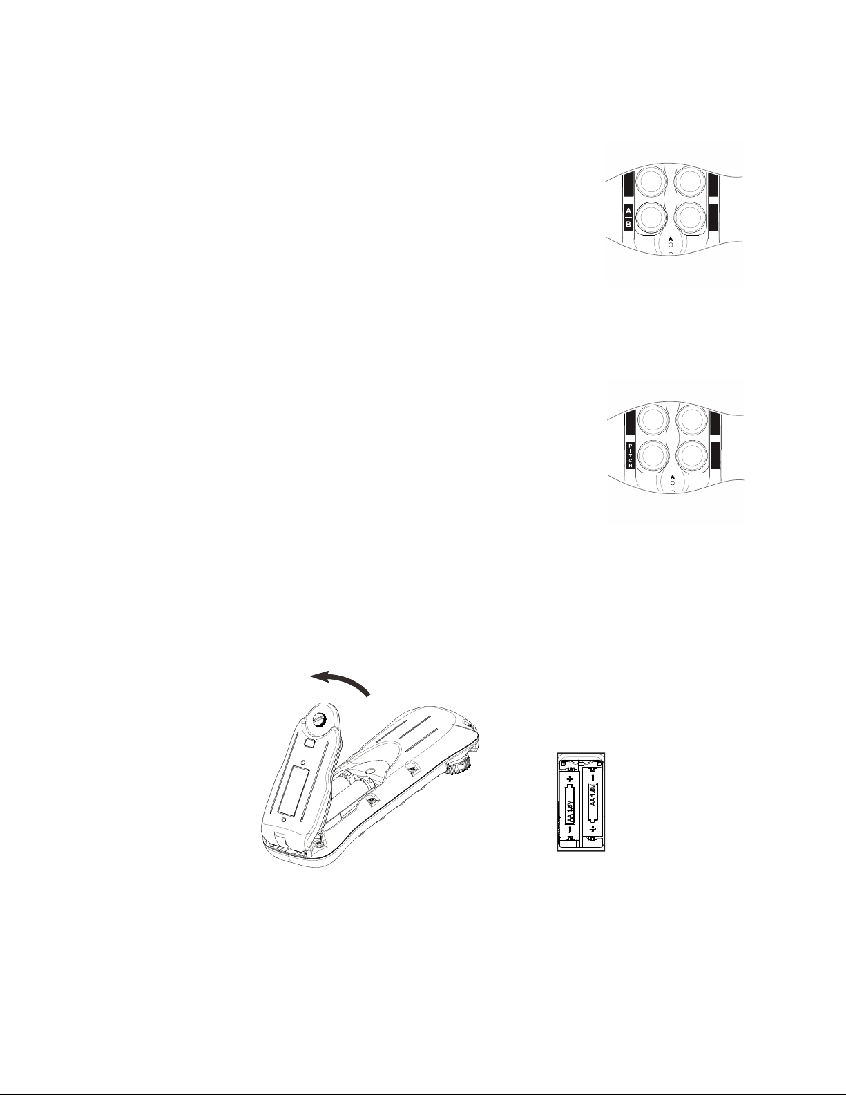
Pressing the “A/B” pushbutton repeatedly toggles between output relay A, B
and A+B respectively. There are four different types of Select A/B
sequences available (refer to Section 4.1.8.2).
Standard – Output relay A activated at A position, output relay B activated at
B position, and both output relays activated at A+B position.
Reversed logic - Output relay A activated at B position, output relay B
activated at A position, and both output relays deactivated
at A+B position. Refer to Section 4.2.4: Jumper SettingsError! Reference source not found..
7.3 Pitch & Catch Operation
Press the “PITCH” pushbutton for up to 2 seconds to release control of the
receiver. Press the START button for up to 1 second to gain control of the
receiver. The second operator is unable to take control of the receiver
unless the first
4.2.2.9 and Section 4.2.3.2 on how to set to this function.
operator presses the “PITCH” pushbutton. Refer to Section
7.4 Changing Batteries
Change the transmitter batteries (“AA” alkaline battery x 2) by unscrewing the battery cover located
on the backside of the transmitter. During battery installation make sure the batteries are installed
correctly, with “+” to “+” charge and “–” to “–” charge. Also, make sure the screw is tightened after
battery installation to avoid water, moisture, dirt, grease, and other liquid penetration.
Flex 4Base® CE Instruction Manual
January 2017
Page 37 of 41
Page 38
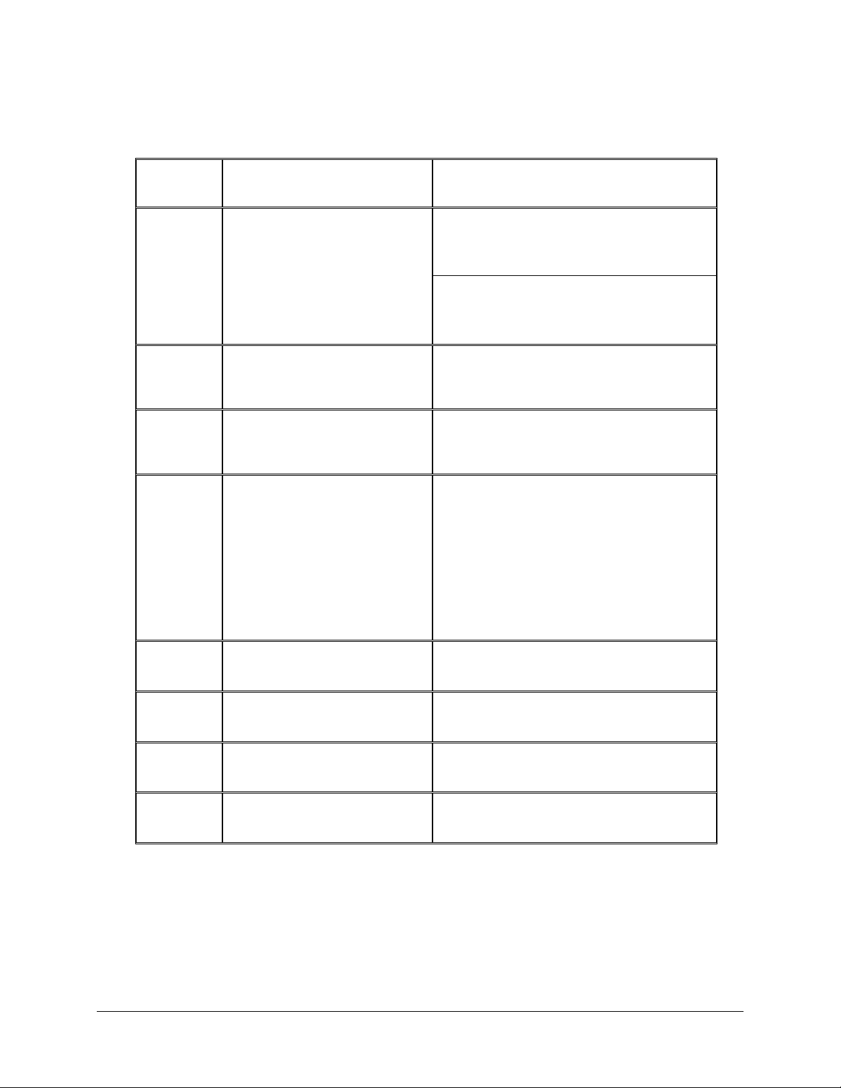
7.5 System Status Light Indications
7.5.1 Transmitter Status Indications
Type Display Type Indication
1
2
3A
3B
Constant red
1 red blink followed by a
2-second pause
2 red blinks followed by a
2-second pause
No light displayed
Voltage below 1.9V at initial power on
(transmitter power and receiver MAIN
relays shut off)
Voltage below 1.8V during operation
(transmitter power and receiver MAIN
relays shut off)
Voltage below 1.85V during operation
(change batteries suggested)
Defective or jammed pushbutton detected
at initial power on
When defective pushbutton condition
occurs (2 red blinks, type 3A above), find
out which pushbutton is defective by
pressing all of them one at a time. If the
pushbutton is in good working order when
pressed, the Status LED is off. If the Status
LED maintained 2 red blinks then
the pushbutton is defective.
4
5
6
7
4 red blinks followed by a
2-second pause
Constant green for up to
2 seconds
Blinking green Transmission in progress
Blinking orange
Transmitter is unable to lock onto the
assigned channel
Transmitter power on with no faults detected
Pressing any pushbutton prior to initiating
the START command at power on
Flex 4Base® CE Instruction Manual
January 2017
Page 38 of 41
Page 39
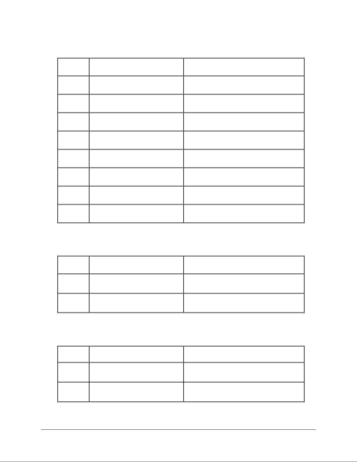
7.5.2 Receiver Status Indications
Type Display Type (Green & Red) Indication
1
2
3
4
5
6
7
8
Fast green blinks Decoding in process
Slow green blinks Decoding on standby
2 red blinks Receiver MAIN relays jammed or defective
3 red blinks Decoding processors defective
4 red blinks Receiving RF defective
Fast red blinks Incorrect transmitter serial number
Constant red Receiver low voltage
No light displayed Decoding processors defective
7.5.3 Receiver Power Indications
Type Display Type (Red) Indication
1
2
On Power to receiver
Off No power to receiver
7.5.4 Receiver COM Indications
Type Display Type (Red) Indication
1
2
On Power to relay Board
Off No power to relay board
Flex 4Base® CE Instruction Manual
January 2017
Page 39 of 41
Page 40

8 General Specifications
Frequency Range : 433.050MHz ~ 434.575MHz
Number of Channels : 62 channels
Channel Spacing : 25 KHz
Modulation : Digital Frequency Modulation based
on Manchester Code, 20bit address,
32bit CRC and Hamming Code.
Encoder & Decoder : Microprocessor-controlled
Transmitting Range : >100 Meters (300 feet)
Hamming Distance : >6
Frequency Control : Synthesized PLL
Receiver Type : Frequency Auto Scanning
Receiver Sensitivity : -116dBm
Spurious Emission : -50dB
Antenna Impedance : 50 ohms
Responding Time : 40mS (average)
Transmitting Power : 5.0mW
Enclosure Type : NEMA4
Enclosure Rating : IP66
Output Contact Rating : 250V @ 8 Amps
Transmitter Operating Voltage : 3.0VDC
Receiver Power Consumption : 3~7VA
Available Receiver Voltages : 9~36VDC
24VAC
42VAC
48VAC
110~120VAC
220~240VAC
380~400VAC
410~460VAC
Operating Temperature : -25°C ~ 75°C / -13°F ~ 167°F
Transmitter Dimension : 141mm (L) x 69mm (W) x 38mm (H)
Receiver Dimension : 196mm (L) x 149mm (W) x 85mm (H)
Transmitter Weight : 203g / 7.2oz (include batteries)
Receiver Weight : 1.5kg / 3.3lb (include output cable)
Flex 4Base® CE Instruction Manual
January 2017
Page 40 of 41
Page 41
9 EU Declaration of Conformity
(EMC, R&TTE, SAFETY & MACHINERY)
For the following equipment:
Product : Flex ECO (Base) Series Radio Remote Control System
Multiple Listee Model No. : Flex ECO (Base) 4S/4X, ECO (Base) 8S/8X,
ECO (Base) 12S/12X
Manufacturer’s Name : Advanced Radiotech Corporation
Manufacturer’s Address : : 1F, 288-1, Hsin Ya Road, Chien Chen District,
Kaohsiung, Taiwan
We hereby declare, that all major safety requirements, concerning the CE Mark Directive 2006/42/EC and
Low Voltage Directive 2006/95/EC, Electromagnetic Compatibility Directives 2004/108/EC, R&TTE
Directive 1999/5/EC are fulfilled, as laid out in the guideline set down by the member states of the EEC
Commission.
The standards relevant for the evaluation of the electrical safety requirements are as
follow:
EMC : EN 301 489-1 + EN 301 489-3
R&TTE : EN 300 220-1 V2.3.1 + EN 300 220-2 V2.3.1
SAFETY : EN 60950:2006+A1+A11+A12
MACHINERY : EN 60204-32:2008, EN 13557:2003+A1:2008
EN ISO 13849-1:2008 (PL=d), EN 60529 (IP66)
Test reports issued by:
EMC : SGS
R&TTE : SGS
SAFETY : SGS
MACHINERY : SGS
Person responsible for marking this declaration:
Tom Jou / President
Name and signature of authorized person
Flex 4Base® CE Instruction Manual
January 2017
Page 41 of 41
 Loading...