

Page 1
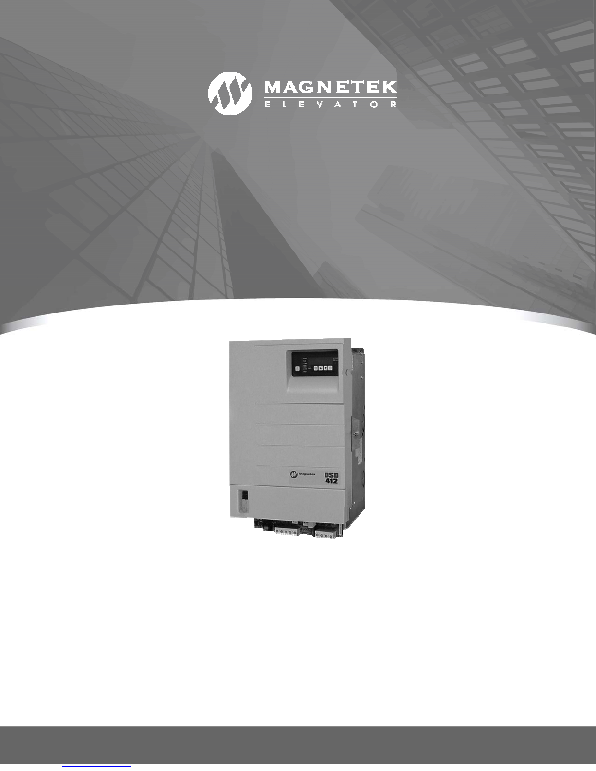
DSD 412
DSD 412 DC Elevator Drive
To properly use the product, read this manual thoroughly and retain for easy reference, inspection,
and maintenance. Ensure that the end user receives this manual.
Technical Manual
© Magnetek Elevator 2016
CS00407 rev 11
U39 / U40 97SA407x-0010 Rv16
U13 / U14 97SA404x-0008 Rv08
Page 2

Warranty
Standard products manufactured by the Company are warranted to be free from defects in
workmanship and material for a period of one year from the date of shipment, and any
products, which are defective in workmanship or material, will be repaired or replaced, at the
Company’s option, at no charge to the Buyer. Final determination as to whether a product is
actually defective rests with the Company. The obligation of the Company hereunder shall
be limited solely to repair or replace, at the Company’s discretion, products that fall within
the foregoing limitations, and shall be conditioned upon receipt by the Company of written
notice of any alleged defects or deficiency promptly after discovery and within the warranty
period, and in the case of components or units purchased by the Company, the obligation of
the Company shall not exceed the settlement that the Company is able to obtain from the
supplier thereof. No products shall be returned to the Company without its prior consent.
Products, which the company consents to have returned, shall be shipped prepaid f.o.b. the
Company factory. The Company cannot assume responsibility or accept invoices for
unauthorized repairs to its components, even though defective. The life of the products the
Company depends, to a large extent, upon type of usage thereof and THE COMPANY
MAKES NO WARRANTY AS TO FITNESS OF ITS PRODUCTS FOR THE SPECIFIC
APPLICATIONS BY THE BUYER NOR AS TO PERIOD OF SERVICE UNLESS THE
COMPANY SPECIFICALLY AGREES OTHERWISE IN WRITING AFTER PROPOSED
USAGE HAS BEEN MADE KNOWN TO IT.
This warranty does not apply to experimental products for which no warranty is made or
given and Buyer waives any claim thereto.
THE FOREGOING WARRANTY IS EXCLUSIVE AND IN LIEU OF ALL OTHER
WARRANTIES, EXPRESSED OR IMPLIED, INCLUDING, BUT LIMITED TO, ANY
WARRANTY OF MECHANTIBILITY OR OF FITNESS FOR A PARTICULAR PURPOSE
AND BUYER HEREBY WAIVES ANY AND ALL CLAIMS THEREFORE.
Limitations Of Liability
IN NO EVENT SHALL MAGNETEK BE LIABLE FOR LOSS OF PROFIT, INDIRECT,
CONSEQUENTIAL OR INCIDENTAL DAMAGES WHETHER ARISING OUT OF
WARRANTY, BREACH OF CONTRACT OR TORT.
DSD 412 is a trademark of Magnetek, Inc.
All rights reserved. No part of this publication may be reproduced or used in any form or by any means - graphic, electronic, or
mechanical including photocopying, recording, taping, or information storage and retrieval systems - without written permission
of the publisher.
2016 Magnetek, Inc.
Page 3

Table of Contents
Introduction ............................................................................................................. 11
Drive Description ............................................................................................................................. 11
The Standard Control Display Unit (SCDU) .................................................................................... 11
The Portable Control Display Unit (PCDU) ..................................................................................... 11
Drive Ratings and Specifications ................................................................................................... 11
Basic Drive Specifications ............................................................................................................... 11
Service Conditions .......................................................................................................................... 11
Protective Features ......................................................................................................................... 11
Software Operating Features .......................................................................................................... 12
Power Conversion Unit .................................................................................................................... 17
Description ...................................................................................................................................... 17
Hardware Descriptions .................................................................................................................... 17
DSD 412 Power Supply PCB (A4) .................................................................................................. 17
Armature Interface PCB (A2) .......................................................................................................... 17
SCR's .............................................................................................................................................. 18
Field Interface PCB (A3) ................................................................................................................. 18
Cell snubber PCB (A5) .................................................................................................................... 18
Drive Control PCB (A1) ................................................................................................................... 18
Precautionary Statements ............................................................................................................... 20
How To Contact Magnetek .............................................................................................................. 20
Pre-Installation Considerations ...................................................................................................... 21
Receipt of Shipment ........................................................................................................................ 21
Unpacking Instructions .................................................................................................................... 21
Packing Instructions for Reshipment or Storage ............................................................................ 21
Physical Installation ........................................................................................................................ 21
Selecting, Mounting and Wiring of the Digital Encoder ............................................................... 21
Encoder Selection ........................................................................................................................... 21
Mounting ......................................................................................................................................... 21
Coupling .......................................................................................................................................... 22
Exceeding Operating Specification ................................................................................................. 22
Electrical Hook up ........................................................................................................................... 23
Power Connections ......................................................................................................................... 23
Signal Connections ......................................................................................................................... 23
Grounding ....................................................................................................................................... 23
Pre-power Check ............................................................................................................................ 23
Drive Start up .................................................................................................................................... 24
Drive power-up sequence ............................................................................................................... 24
Abnormal Display Conditions .......................................................................................................... 24
Fan Check ....................................................................................................................................... 24
Verify Parameters ........................................................................................................................... 24
Interconnect Drawings .................................................................................................................... 25
Standard Control/Display Unit Operation ............................................................. 31
General ........................................................................................................................................... 31
Start-Up Operation .......................................................................................................................... 31
After Power-Up ................................................................................................................................ 32
Changing Parameter Functions ...................................................................................................... 32
Viewing Monitor Functions .............................................................................................................. 33
Error Reporting ................................................................................................................................ 33
Fault Display/Clear .......................................................................................................................... 35
Error Display ................................................................................................................................... 35
Non-Volatile Ram Access ............................................................................................................... 36
Load Default Function ..................................................................................................................... 37
1
Page 4

Self Tune Function .......................................................................................................................... 37
Power Conversion Diagnostics ....................................................................................................... 39
Drive Setup & Adjustments .................................................................................... 41
Motor Field Current Control ............................................................................................................ 41
Analog Velocity Follower ................................................................................................................. 41
Internal Preset Speed & Profile Generator ..................................................................................... 41
Serial Link Follower ......................................................................................................................... 41
Armature Voltage Feedback ........................................................................................................... 41
Pre-Torque, Function #114 ............................................................................................................. 41
Current Ramp-Down, Function #85 ................................................................................................ 41
Electronic Motor Over-Load ............................................................................................................ 42
External/Auto Fault Reset, Function #101 ...................................................................................... 42
Over-Speed Test, Functions #80 and #81 ...................................................................................... 42
Brake Control Logic, Functions #186 and #183 .............................................................................. 42
Speed Regulator Adjustment/E-Reg ............................................................................................... 43
Field Regulator Set-Up ................................................................................................................... 45
AC Input Voltage Requirement & Adjustment ................................................................................. 45
Adjustment Function Descriptions ................................................................................................ 59
Display Monitor Functions .............................................................................................................. 76
Miscellaneous Functions ................................................................................................................ 78
Drive Faults ............................................................................................................. 79
Function Error Code Listing ........................................................................................................... 79
Troubleshooting .............................................................................................................................. 80
Input – Output Signal Verification ......................................................................... 89
Maintenance ............................................................................................................ 91
Preventive Maintenance ................................................................................................................. 91
Repair and Replacement Procedures ............................................................................................. 91
Printed Circuit Boards ..................................................................................................................... 91
Drive Control PCB Replacement .................................................................................................... 97
IC Replacement .............................................................................................................................. 97
Testing and Replacement of Power Components. ......................................................................... 97
Testing and Replacement of Power Semiconductors and Snubber Components. ........................ 98
Testing and Replacement of the Motor Field Control Module and PCB ......................................... 98
Repair of the 195Amp Assembly .................................................................................................... 99
Repair of the 300Amp Assembly .................................................................................................. 100
Appendix ................................................................................................................ 104
Drive Ratings for Elevator Applications ...................................................................................... 104
Power Loss ..................................................................................................................................... 105
Wire Terminal Specs ...................................................................................................................... 106
Power Terminal Wire Sizes ........................................................................................................... 106
Ground Wire Sizes ........................................................................................................................ 106
Field Interface Board (TB1, TB4) .................................................................................................. 106
Spare Parts ..................................................................................................................................... 107
Packing Instructions ...................................................................................................................... 110
Outline Drawings ............................................................................................................................ 111
Index ....................................................................................................................... 117
2
Page 5
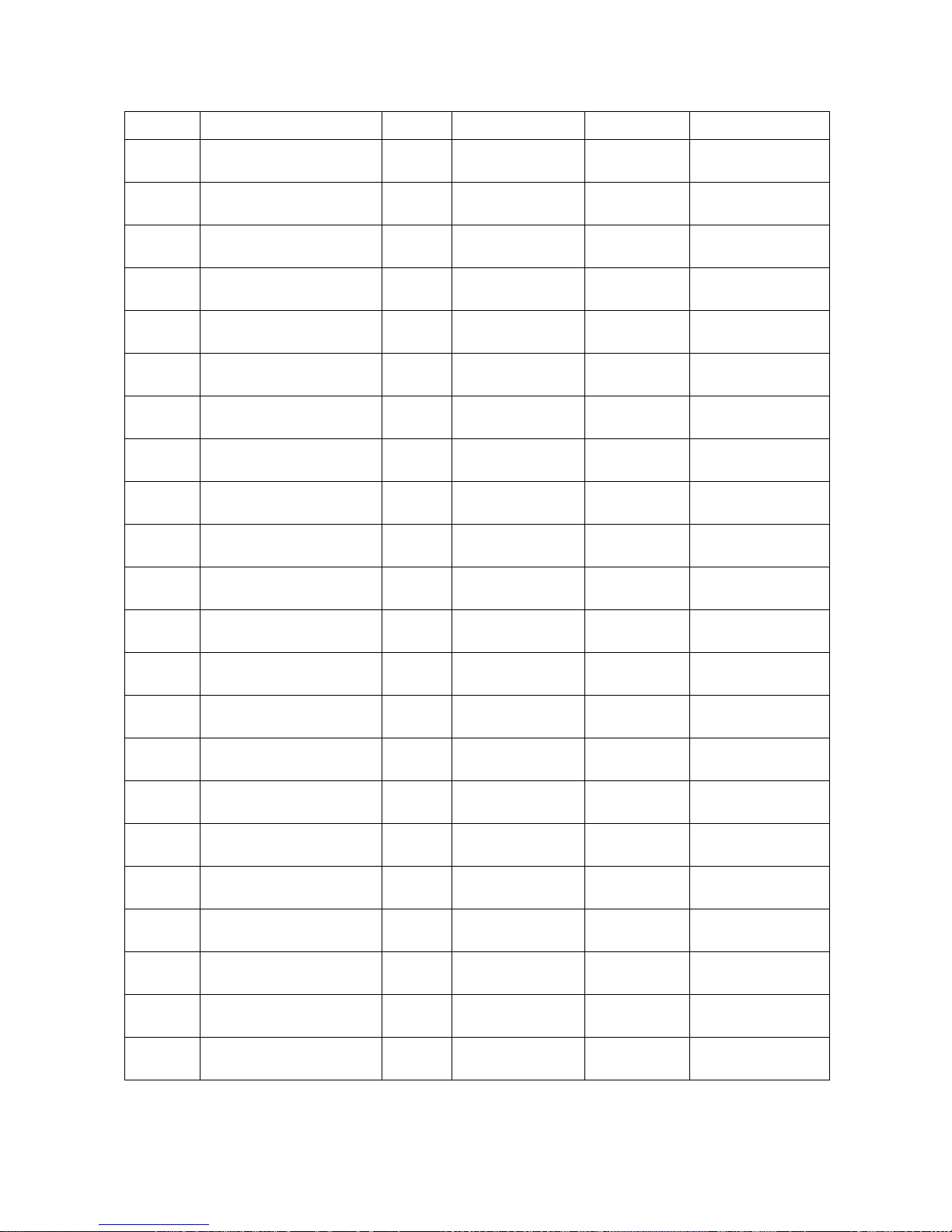
Quick Reference for Setup Parameters
FNCT. # DESCRIPTION UNIT RANGE DEFAULT SITE SETTING
1 CURRENT LIMIT. % 0 - 300 250
2
3 RTD. ARMATURE AMPS ADC 2.0 - 1250.0 50.0
4 ARMATURE OHMS OHMS 0.001 - 5.000 0.100
6
7 RTD. ARMATURE VOLTS VDC 150 - 550 240
8 I REG CROSSOVER RAD 100 - 1000 500
9 NOMINAL AC INPUT VAC 150 - 525 230
10 ENCODER PPR P/R 600 - 19999 1024
11 RATED MOTOR RPM RPM 50.0 - 1999.0 1150.0
USE SELF- TUNE
VALUES
ARMATURE
INDUCTANCE
LOGIC 0 - 1 0=OFF
HNY 0.0010 -1.000 0.0100
12 OVERSPEED % % 0.0 - 150.0 110.0
14 V SENSE % % 0.0 - 100.0 25.0
15 T SENSE % % 0.0 - 100.0 5.0
16 ENCDR / MTR RATIO - 1.000 - 19.000 1.000
17 RATED CAR SPEED - 1.0 - 1900.0 400.0
21 EXT ACCEL LIMIT - 2.00 - 10.00 4.20
22 ERROR LIST RESET LOGIC 0 - 1 0=OFF
32 FULL FIELD DETECT % 30 - 90 80
38 ARM VLT RESPONSE RAD 1.0 - 4.0 2.0
39 HI SPEED BANDWIDTH RAD 1.0 – 15.0 6.0
40 LO SPEED BANDWIDTH RAD 1.0 – 15.0 6.0
41 PER-UNIT INERTIA SEC 0.10 - 9.99 2.00
3
Page 6
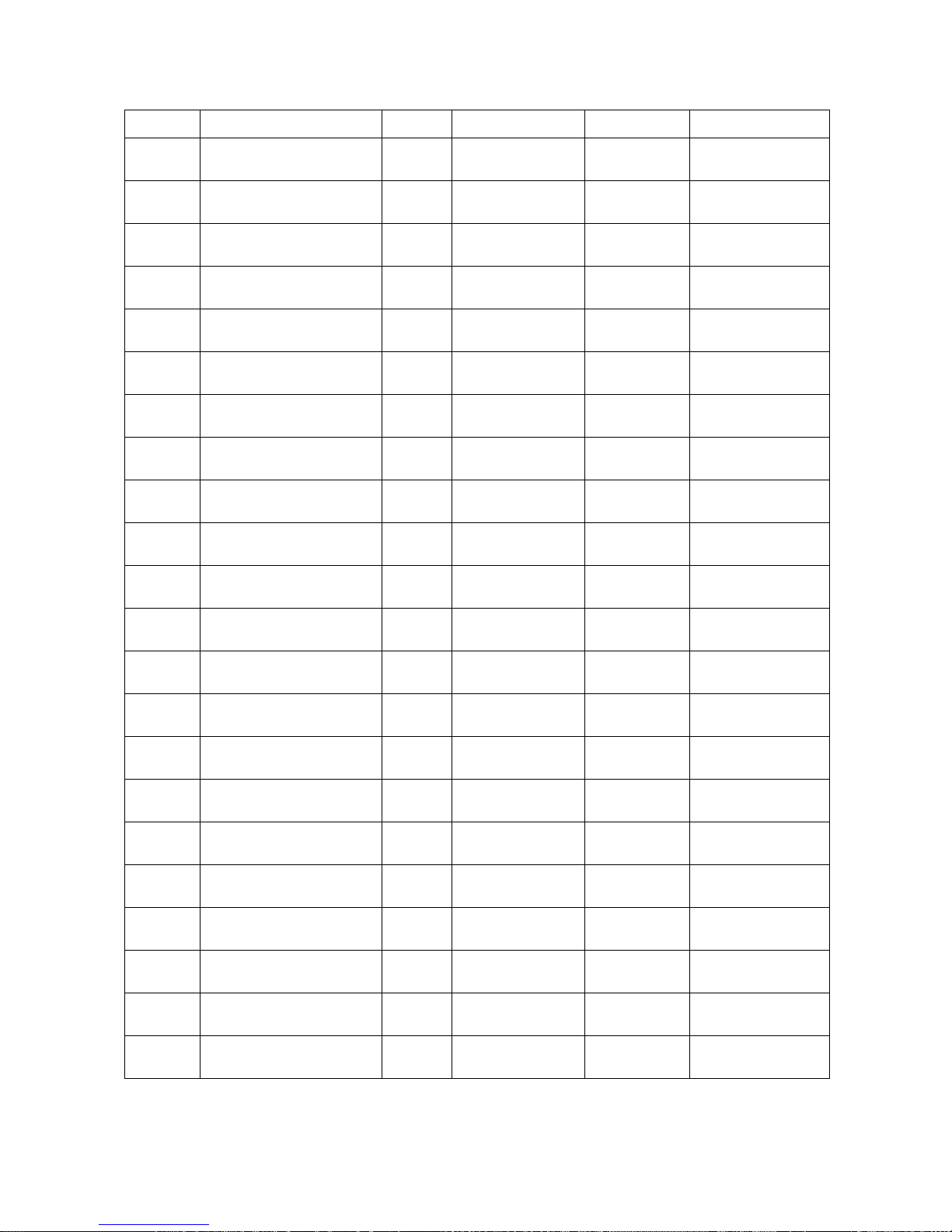
Quick Reference for Setup Parameters
FNCT. # DESCRIPTION UNIT RANGE DEFAULT SITE SETTING
42 STIFFNESS - 0.2 - 9.9 1.0
49 WEAK FIELD CURRENT ADC 0.20 - 40.00 40.00
50 FULL FIELD CURRENT ADC 0.20 - 40.00 1.90
51 MOTOR FIELD L/R SEC 0.10 - 10.00 0.54
52 RTD. FIELD VOLTS DC VDC 50 - 525 240
53 STANDBY FIELD AMPS % 10 - 100 25
54 FIELD RESPONSE RAD 1.0 - 10.0 5.0
55
63 U/D PICK-UP % 0.01 - 100.00 0.10
64
80 OVER SPEED TEST LOGIC 0 - 1 0=OFF
81 OVER SPEED MULT - 1.00 - 1.50 1.00
82 REFERENCE MULT - -2.000 - 2.000 1.000
83 MOTOR OVERLD TIME SEC 2.0 - 500.0 48.0
84 MOTOR OVERLD LEVEL PU 0.50 – 2.00 1.15
85 I DECAY RAMP SEC 0.01 - 2.50 0.20
86 ANALOG SPD REF ZERO PU -0.2000 - +0.2000 0.0000
87 PRE-TORQUE MULT - 0.25 - 2.00 1.00
FIELD CONTROL AC
SOURCE VOLTS
LOW SPEED
THRESHOLD
VAC 0 - 525 0
% 0.1 - 100.0 2.0
88 DSPR DELAY TIME MIN 0 - 60 0 (OFF)
89 BRAKE PICK TIMER SEC 0.5 - 5.0 1.0
90 BRAKE DROP TIMER SEC 0.5 - 5.0 1.5
91 MUST STOP TIMER SEC 0.1 - 5.0 2.0
4
Page 7
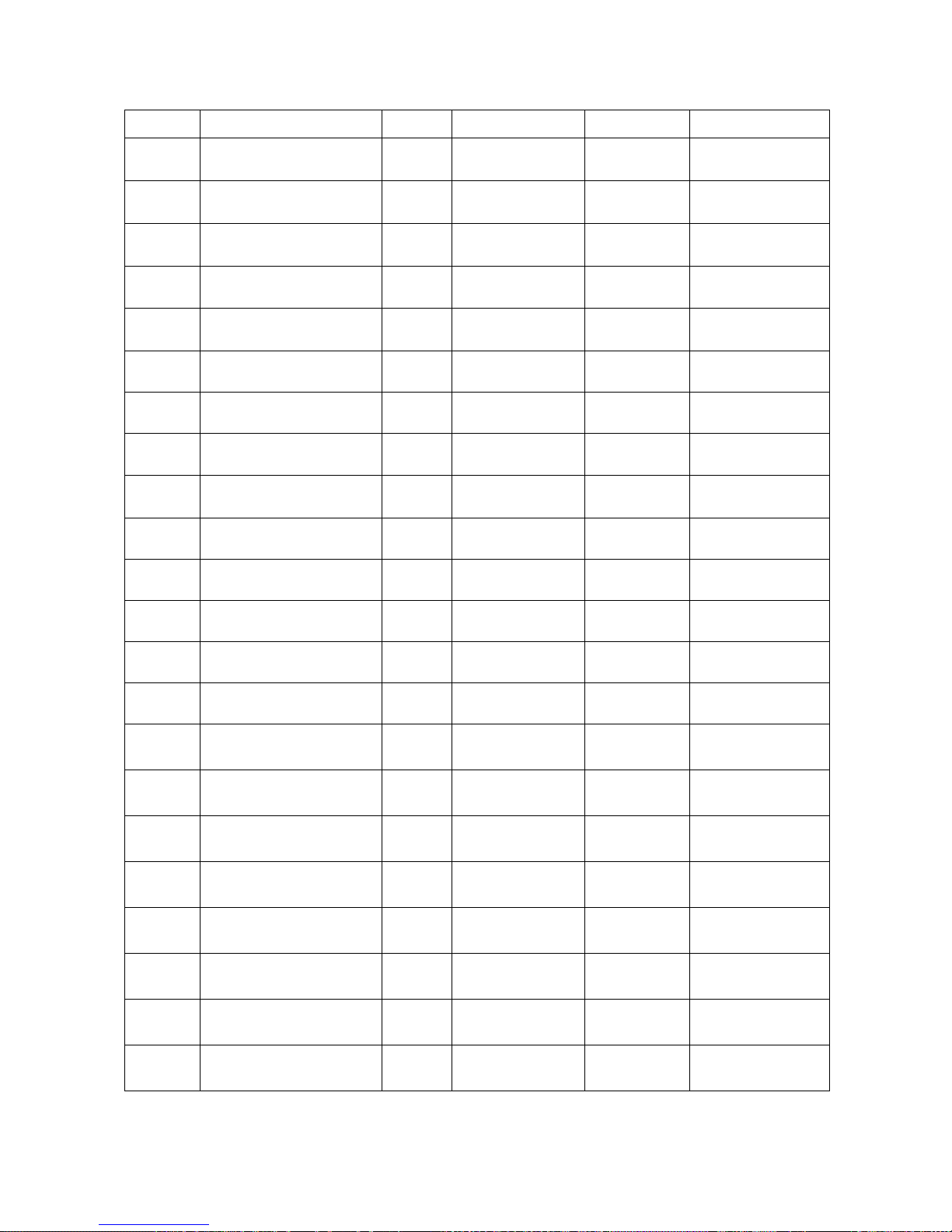
Quick Reference for Setup Parameters
FNCT. # DESCRIPTION UNIT RANGE DEFAULT SITE SETTING
92 BRAKE AUTO STOP ON LOGIC 0 - 1 0=OFF
93 ANALOG OUT 0 BIAS - -1.00 - +1.00 0.00
94 ANALOG OUT 1 BIAS - -1.00 - +1.00 0.00
95
96
97 ANALOG OUT 0 MULT - 00.10 - 10.00 0.80
98 ANALOG OUT 1 MULT - 00.10 - 10.00 0.80
99
100
101 AUTO FAULT RESET ON LOGIC 0 - 1 0=OFF
102 3S LOOP FLT LOGIC 0 - 1 0=OFF
104 SERIAL GAIN SWITCH LOGIC 0 - 1 0=OFF
105 GAIN SWITCH SPEED PU 0.00 - 1.10 1.10
107 TACH RATE GAIN % 0.0 - 30.0 0.0
ANALOG OUT 0 SELECT
TB1(45)
ANALOG OUT 1 SELECT
TB1(46)
SPEED ERROR TRIP
TIME
SPEED ERROR TRIP
LEVEL
NUM 0 - 8 1
NUM 0 - 8 3
SEC 0.20 - 5.00 5.00
% 0.0 - 100.0 100.0
110
111 ARCH TRAV DISABLE LOGIC 0 - 1 1=ON
112 FEEDBACK SELECT NUM 0 - 1
113
114 PRE-TORQUE ENABLE LOGIC 0 - 1 0=OFF
115 RNUP RNDN ENABLE LOGIC 0 - 1 0=OFF
116 DECEL RATE LATCH LOGIC 0 - 1 0=OFF
117 PRETORQUE BIAS PU 0.00 – 1.00 0.00
REFERENCE MODE
SELECT
ARM VOLTS @ MAX
SPEED
NUM 1 – 5 2
1 =
ENCODER
VDC 0.0 – 650.0 100.0
5
Page 8
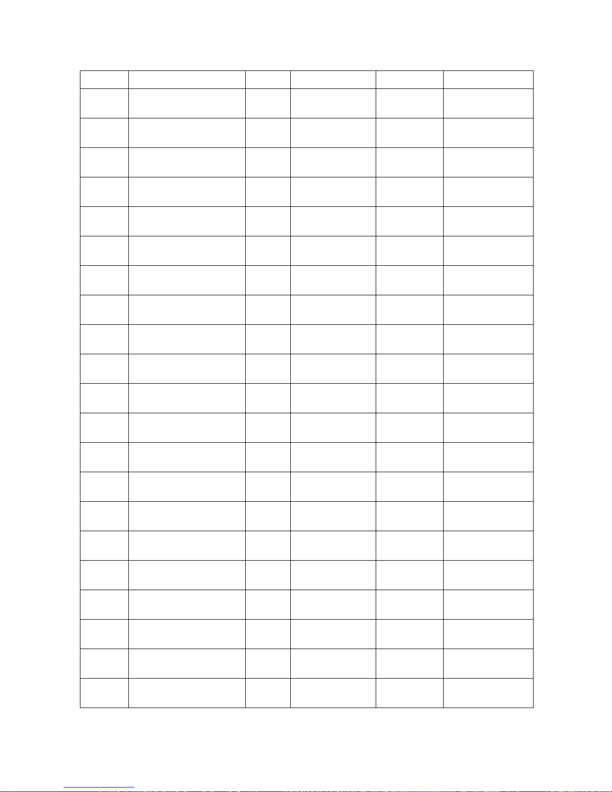
Quick Reference for Setup Parameters
FNCT. # DESCRIPTION UNIT RANGE DEFAULT SITE SETTING
120
121
130 ARB MODE NUM 0 – 2 0 (OFF)
131 ARB BANDWIDTH RAD 1.0 – 15.0 6.0
132 ARB DAMPING - 0.01 –20.00 2.00
133 ARB SPD THRESHOLD % 0.0 – 10.0 0.0
150 BINARY SELECT ON LOGIC 0 – 1 1=ON
151 PRESET SPEED #1 - 0.0 – 1900.0 0.0
152 PRESET SPEED #2 - 0.0 –1900.0 0.0
153 PRESET SPEED #3 - 0.0 – 1900.0 0.0
SPEED ERROR DETECT
TIME
SPEED ERROR
THRESHOLD
SEC 0.0 – 5.0 0.5
% 0.0 – 15.0 2.0
154 PRESET SPEED #4 - 0.0 – 1900.0 0.0
155 PRESET SPEED #5 - 0.0 – 1900.0 0.0
156 PRESET SPEED #6 - 0.0 – 1900.0 0.0
157 PRESET SPEED #7 - 0.0 – 1900.0 0.0
170 ACCEL #1 TIME SEC 1.00 – 15.00 5.00
171 ACCEL #2 TIME SEC 1.00 – 15.00 5.00
172 DECEL #1 TIME SEC 1.00 – 15.00 5.00
173 DECEL #2 TIME SEC 1.00 – 15.00 5.00
174 ACCEL #1 % S % 0.1 – 100.0 25.0
175 ACCEL #2 % S % 0.1 – 100.0 25.0
176 DECEL #1 % S % 0.1 – 100.0 25.0
6
Page 9
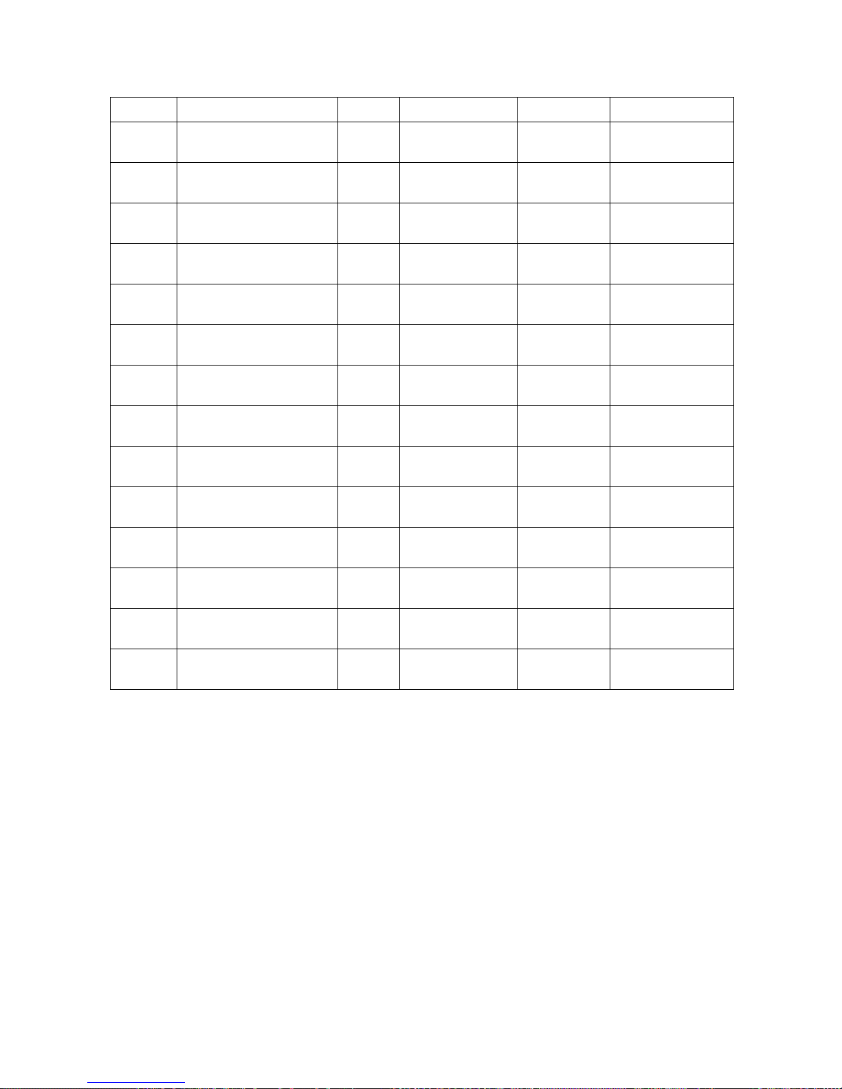
Quick Reference for Setup Parameters
FNCT. # DESCRIPTION UNIT RANGE DEFAULT SITE SETTING
177 DECEL #2 % S % 0.1 – 100.0 25.0
178 ACCEL #3 TIME SEC 1.00 – 15.00 5.00
179 DECEL #3 TIME SEC 1.00 – 15.00 5.00
180 ACCEL #3 % S % 0.1 – 100.0 25.0
181 DECEL #3 % S % 0.1 – 100.0 25.0
182 INVERT ALARM RELAY LOGIC 0 – 1 0=OFF
183 K3 LGC OUT SELCT NUM 1 – 4 1
184 K4 LGC OUT SELCT NUM 1 – 4 1
185 K5 LGC OUT SELCT NUM 1 – 4 1
186 K6 LGC OUT SELCT NUM 1 – 4 1
187 K7 LGC OUT SELCT NUM 1 – 4 1
190 NOTCH DEPTH - 0 – 10 0
191 NOTCH PERIOD - 0 – 10 7
192 F413 DETECTION LVL PU 0.05 – 0.50 0.05
Table 1: Drive Parameters
7
Page 10
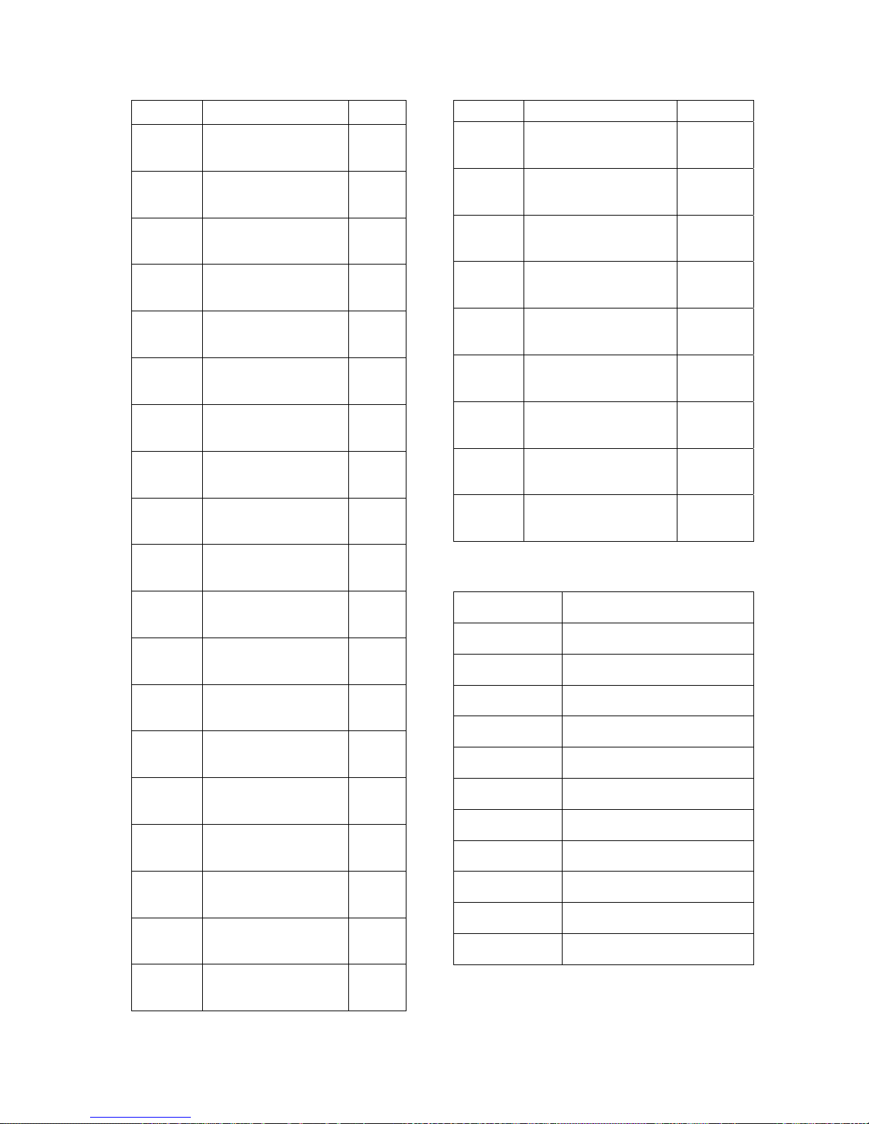
Read-Out and Control Parameters
FNCT. # DESCRIPTION UNIT
FNCT. # DESCRIPTION UNIT
600 CAR SPEED -
601 MOTOR RPM RPM
602 SPEED REF -
603 PRE-TORQ SIGNL %
609 CEMF VOLTS VDC
610 MOTOR ARM V VDC
611 MOTOR ARM I ADC
612 MOTOR FIELD I ADC
613 MEASURED R OHM
690 PCU - VERSION -
691 PCU - RELEASE -
692 DAY -
693 MONTH -
695 YEAR -
696 BETA “P” -
697 VERSION “SA” -
698 DCU -RELEASE -
699 CUSTOMER ID -
614 MEASURED L HNY
615 MEAS. FIELD L/R SEC
616
617 LINE FREQ HZ
618 HEAT SINK TEMP DEG C
619
620 FIELD TRACKING PU
621 SERIAL COMM ON LOGIC
688 CUBE I.D. -
689 FIELD RANGE -
MEASURED SPEED
ERROR
MEASURED AC LINE
VOLTS
%
VAC
Table 2: Monitor Functions
FNCT. # DESCRIPTION
22 CLEAR ERRORS LIST
000 VIEW FAULT LIST
800 VIEW ERROR LIST
801 FAULT/ERROR ACTIONS
980 TRACE MONITOR
981 VERIFY I/O
993 CLEAR NV RAM
994 SAVE/RECALL FUNCTION
995 LOAD DEFAULTS
997 SELF TUNE
998 PCU DIAGNOSTICS
Table 3: Misc Commands
8
Page 11
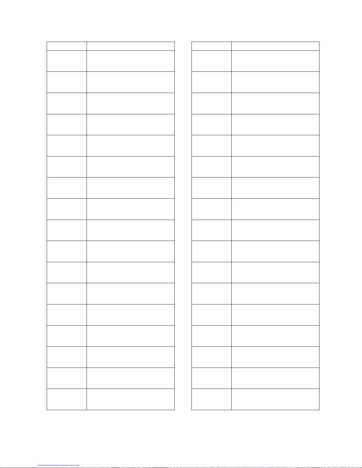
FAULT # DESCRIPTION
Common Fault References
FAULT # DESCRIPTION
97 OVERSPEED TRIP
98 TACH/ENCODER LOSS
99 REVERSE TACH/ENCODER
117/118 SERIAL COM FAULT
400 MOTOR OVERLOAD
401
402 CONTACTOR FAULT
403 5 MIN FULL FIELD FAULT
404
EXCESSIVE FIELD
CURRENT
OPEN ARMATURE CIRCUIT
FAULT
414
Prot CORRUPTED NV RAM DATA
900 PCU LOOP FAULT
901 PCU IST FAULT
902 POWER SUPPLY FAULT
903 LINE SYNC FAILURE
904 LOW LINE FAULT
905 FIELD LOSS
907 THERMISTOR FAULT
SOFTWARE
COMPATABILITY FAULT
405 SAFETY CIRCUIT FAULT
406 10% LOW LINE ALARM
407 DCU CEMF ALARM
408 PCU CEMF FAULT
409 PCU RESET FAULT
410 SPEED ERROR TRIP FAULT
411
413
MAXIMUM AUTO RESETS
FAULT
FIELD CURRENT TRACKING
FAULT
908 OVER TEMPERATURE
909 EXCESSIVE RIPPLE
910 BLOWN FUSE
915 PARAMETER SETUP
917
919
920
921 BRIDGE RATING FAULT
REVERSE ARM. V.
FEEDBACK
RATED VAC. SETTING
ERROR
RATED ARM. VOLT.
SETTING
9
Page 12
Common Fault References
FAULT # DESCRIPTION
FAULT # DESCRIPTION
923
924
925 FIELD PCB SENSE FAULT
926 PCU WATCHDOG
929
930
931
932
933
RATED ARM. I. SETTING
ERROR
RATED FIELD I. SETTING
ERROR
IFLD FB CANNOT BE
REDUCED TO ZERO
DURING SELFTUNE.
IFLD FB CANNOT GET TO
RATED
EXCESS OPEN CIRCUIT
VOLTAGE DURING
SELFTUNE.
ARMATURE CEMF
VOLTAGE IN XCESS
DURING SELFTUNE.
IARM DOES NOT INCREASE
TO NEAR TEST AMPS
DURING SELFTUNE.
934
935
936
937
938
939
940
941
CALC ARML IS UNDER
RANGE DURING SELFTUNE.
VOLTAGE FEEDBACK AND
BUS VOLTAGE DOESN’T
MATCH DURING SELFTUNE
ESTOP CONTACT WAS
OPENED DURING SELF
TUNE
LOW READ BACK VOLTAGE
FEEDBACK DURING
SELFTUNE
LOW READ BACK FROM DC
BUS CIRCUIT DURING
SELFTUNE
FAULTY HARDWARE IN THE
FIELD INTERFACE CIRCUIT
FIELD A/D READING IS
SATURATED
MOTOR THERMOSTAT
OPEN
Table 4: Fault References
10
Page 13

Introduction
Drive Description
The DSD 412 Drive is a complete digital
system drive that provides individual drive and
system control in one compact package. It is
of 12SCR Regenerative configuration.
The drive uses two microprocessors, one for
the Power Conversion Unit (PCU) circuitry,
and one for the Drive Control Unit (DCU)
circuitry. Interface to other equipment is
provided with Local I/O [Input/Output], or RS232 & RS-422 serial communications.
Extensive diagnostics and setup capability are
provided through two Control/Display Units.
Depending on rating of the unit, the power
cube is in one of four chassis sizes. Refer to
the outline dimension drawings furnished in
section 6. Each power cube is designed for
mounting inside a qualified electrical
enclosure. Space allowances for air
circulation, additional components, outgoing
terminals, and wire bends must be provided.
Hinged door swing-out clearance is the same
as the width dimension.
The Standard Control Display Unit
(SCDU)
The SCDU is mounted on the Drive Control
PCB and consists of a 4-1/2 digit numeric LED
display, four push buttons and READ/WRITE
colored LEDs. The SCDU can be used for all
setup functions and many diagnostics.
The Portable Control Display Unit
(PCDU)
The PCDU is an optional hand-held device
that can be plugged into any analog controlled
DSD drive and used for all the same functions
as the SCDU plus some advanced diagnostics.
There exists a version of this PCDU, which will
work with the serial version DSD 412, contact
Magnetek for more information. The PCDU
has two lines of sixteen alphanumeric
characters and a thirty-key keypad.
Parameters are entered and displayed in
common understandable units. The drive can
be completely setup prior to actual running and
changes can be made during operation.
Keypad entry of changed parameters,
protected memory, and factory default values
allow the operator to modify data with
minimum risk to the process.
Introduction
Drive Ratings and Specifications
The DSD 412 Elevator Drive is designed for
connection to a three wire ungrounded power
system, or a four wire grounded or ungrounded
power system.
Basic Drive Specifications
10-300 Amps (Special order up to 1285Amps or
600VAC)
3 Phase, 48/62 Hz
Service Factor
150% full load current for one minute
250% full load current for 5 seconds
Full-wave six-pulse SCR control
Regulation (of set speed) to 0.05% with digital
encoder speed feedback
Current regulated shunt field control
Automatic Field weakening
Self-adapting to incoming line power
Service Conditions
Line voltage 150-525 Vac, ±10%, 3 phase.
115 volt, ±10%, 1 phase control power from a
separate source
Frequency 48-62 Hz
Operating Temperature 0-45° C (55° C max at
DSD chassis)
Altitude to 3300 feet above sea level, derate 5%
for each 1,000 ft above 3300 ft
Relative Humidity 95% (noncondensing)
Protective Features
Programmed memory protection
Self-protected Control V power supply
Fast phase-back of loop current
Contactor interlock for E-Stop
2
I
t motor overload protection
AC line current limiting fuses
Automatic power up test
Control power supply loss detection
Isolated and grounded electronics
Encoder/Tachometer monitoring and loss
protection
Input line monitoring
Phase sequence insensitive
dv/dt protection (snubbers)
1400 PRV Thyristors
Instantaneous over-current protection
Phase loss protection
DC bus fuse
Field current economizer and loss protection
11
Page 14

Introduction
Software Operating Features
The DSD 412 is configured by software to
operate geared and gearless elevators and lifts.
The SA407 Drive Control software contains
desirable feature improvements from the
previous version, SA274. Basic features include:
User choice of operating speed reference
External analog reference follower
Serial link reference follower
Internal reference generator with S-Curve
smoothing, to one of 7 preset speeds (8 speeds
including zero)
User choice of ft/min or m/sec speed
programming and display units
User choice between binary or progressive relay
selected internal preset speeds.
Selectable input control logic for Run-Up / RunDown or Run / Direction relay control with
internal preset speeds.
Magnetek exclusive E-Reg, elevator velocity
regulator
Simplified analog or serial link Pre-Torque
operation to prevent roll-back on starts
Controlled Current Ramp-Down to prevent
elevator brake thumping at stops
Internal frequency notch filter to reject rope
resonance interference.
Closed loop motor field current regulator with
simplified motor field weakening and stand-by
adjustments
Maintenance Armature Voltage Feedback mode.
User selectable choices for relay logic output,
including:
Drive OK / No Faults relay
Invert/Noninvert Alarms Relay
Drive operating, OK to release brake
Car above/below speed X threshold
Car above/below Zero speed threshold
Car Moving Up
Car Moving Down
Speed Error above/below X threshold for Y
seconds.
Drive Standby Power Reduction
User selectable analog diagnostic trace outputs
Diagnostic indicator for verifying logic input and
output conditions
Analog speed reference zero adjustment
Alarm Relay to indicate important but non-critical
conditions
Motor or transformer thermostat over-
temperature
Motor Over-Load
Drive Over-Heating
Low Utility Line Input
Safety related fault trapping with diagnostics,
including:
Motor Over-Current
Motor field Malfunction
Contactor Failure
Severe Utility Line disturbances
Encoder Loss
Over-Speed Trip
User selectable automatic or external
commanded Fault Reset
New features have been arranged to be
compatible with present installations of DSD 412
using General Elevator software SA274. The
factory default settings of software SA407 are
such that it will act like SA274 software. The
user must consciously re-program one or more
selectable features to do otherwise.
Several new useful features have been added
for SA407, plus more diagnostic codes to help
pinpoint the cause of problems when things go
wrong during commissioning. See the
appropriate sections for explanations of AntiRollback, Brake Control, Drive Standby Power
Reduction, and operation with a Uni-Polar
Analog reference. Ramp rates 3 are now
activated by external logic command at A1TB1-
10.
12
Page 15
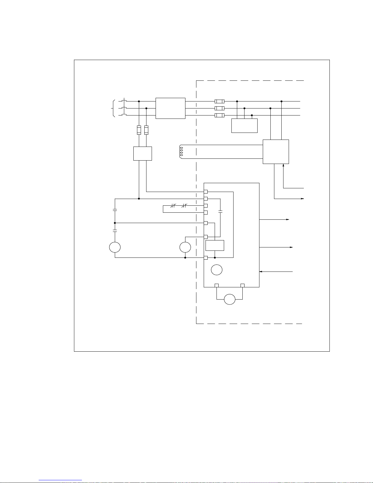
Introduction
CUSTOMER
50/60 Hz
UTILITY
POWER
SAFETY
CHAIN
DISCONNECT
115 VAC
CONTROL
POWER
XFMR
MOTOR &
TRANSFORMER
THERMOSTATS
ISOLATION
TRANSFORMER
HOIST
MOTOR
FIELD
L1
L2
L3
+
F1
F2
F3
SNUBBER PCB
AND
COMPONENTS
MOTOR FIELD
CONTROL
FIELD CONTROL
SCR GATING
POWER
SUPPLY
K1
PCB
LOW VOLTAGE
POWER
FIELD CURR.
SIGNAL
ME
LOOP
CONTACTOR
LPR
LPR
LOOP
PICK-UP
RELAY
E-STOP
SENSE
K1
CONTACTOR
PILOT
RELAY
HEAT SINK
COOLING FAN
Figure 1: DSD 412 Block Diagram A
SIGNAL
SENSING
CONTACTOR
CONTROL
13
Page 16
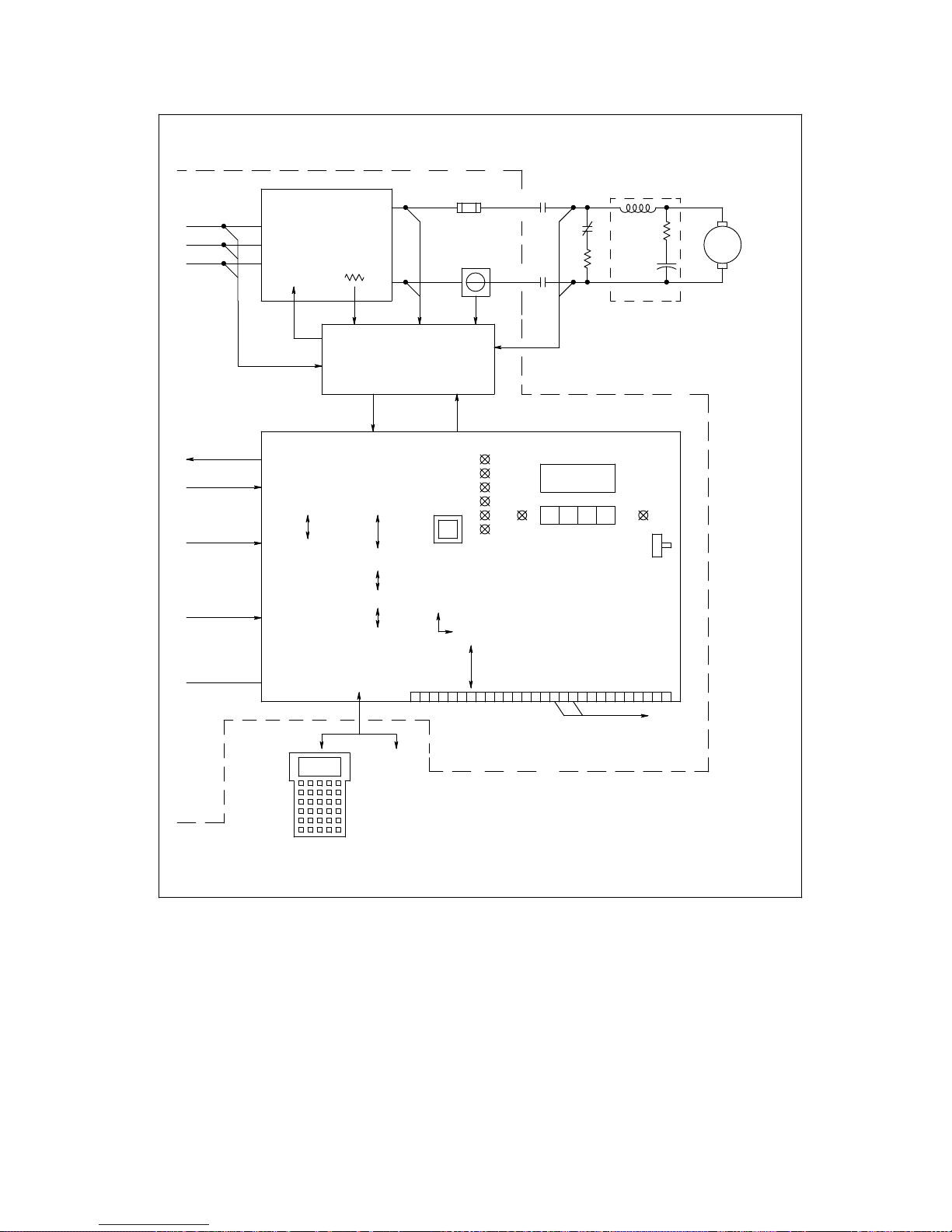
Introduction
SCR POWER BRIDGE
12 SCR REGEN
SCR
GATE
SIGNALS
POWER CONVERSION UNIT
MICROPROCESSOR
RAM &
EPROMS
RT1
ARMATURE
INTERFACE
PCB
DUAL PORT
MEMORY
DRIVE CONTROL UNIT
MICROPROCESSOR
NV-RAM, RAM
& EPROMS
STATUS
LEDS
RESET
DRIVERS
F4
CURRENT
SENSOR
IN-OUT
ME
ME
ME
RESISTOR
+18888
LOCAL CDU
DRIVE CONTROL PCB
DB
RIPPLE FILTER
UN PROT
NV MEM
MEM PROT
SWITCH
MOTOR
ARM.
OPTIONAL
PCDU
PROGRAMMER
RS-232 OR RS-422
SERIAL PORT
OR
TB1 LOCAL CONTROL I / O
OPTIONAL
SERIAL LINK
TO CAR
CONTROLLER
Figure 2: DSD 412 Block Diagram B
CONTROL SIGNAL
WIRING
14
Page 17
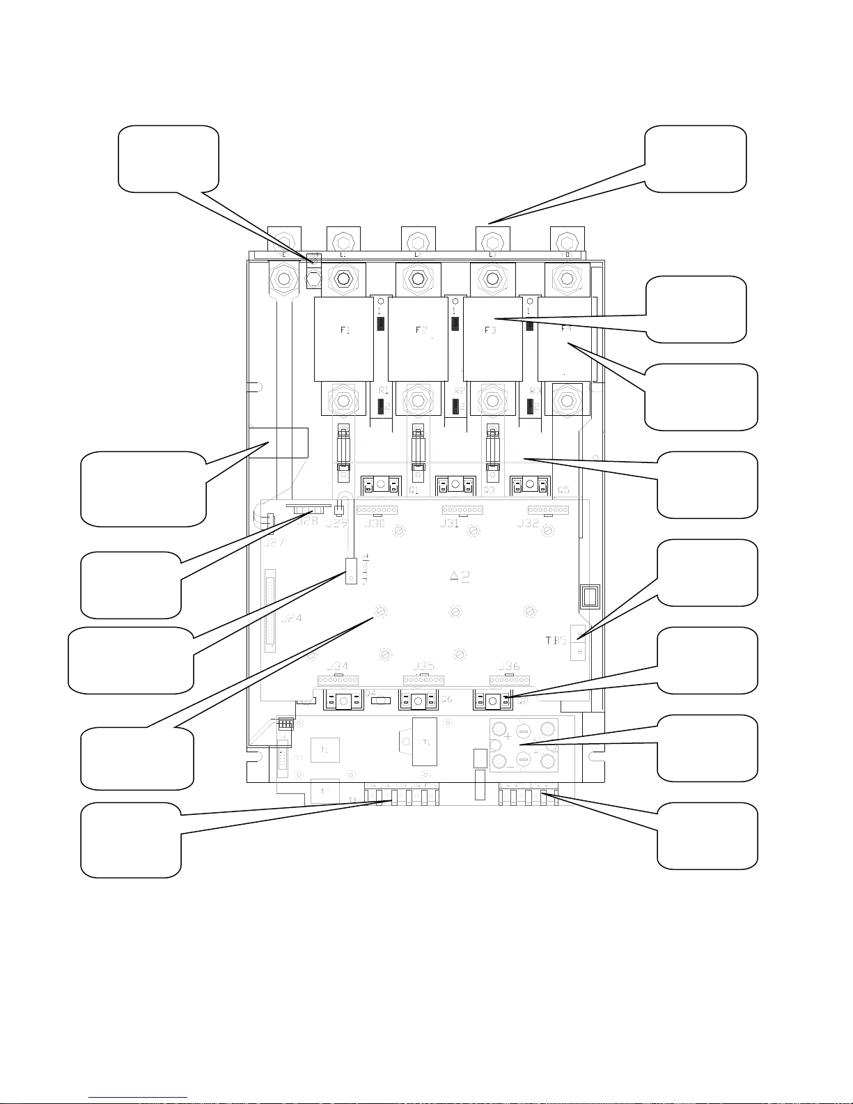
Introduction
GROUND
LUG
ARMATURE
CURRENT
TRANSDUCER
INPUT
POWER
LUGS
AC LINES
FUSES
F1-3
DC
ARMATURE
FUSE F4
SNUBBER
PCB
CUBE I.D.
PCB
BRIDGE
THERMISTOR
ARMATURE
INTERFACE
PCB
DC OUTPUT
FIELD
SUPPLY
Figure 3: Component Layout Front View
A2TB5
SCR'S
Q7, FIELD
SCR
AC INPUT
FOR FIELD
SUPPLY
15
Page 18
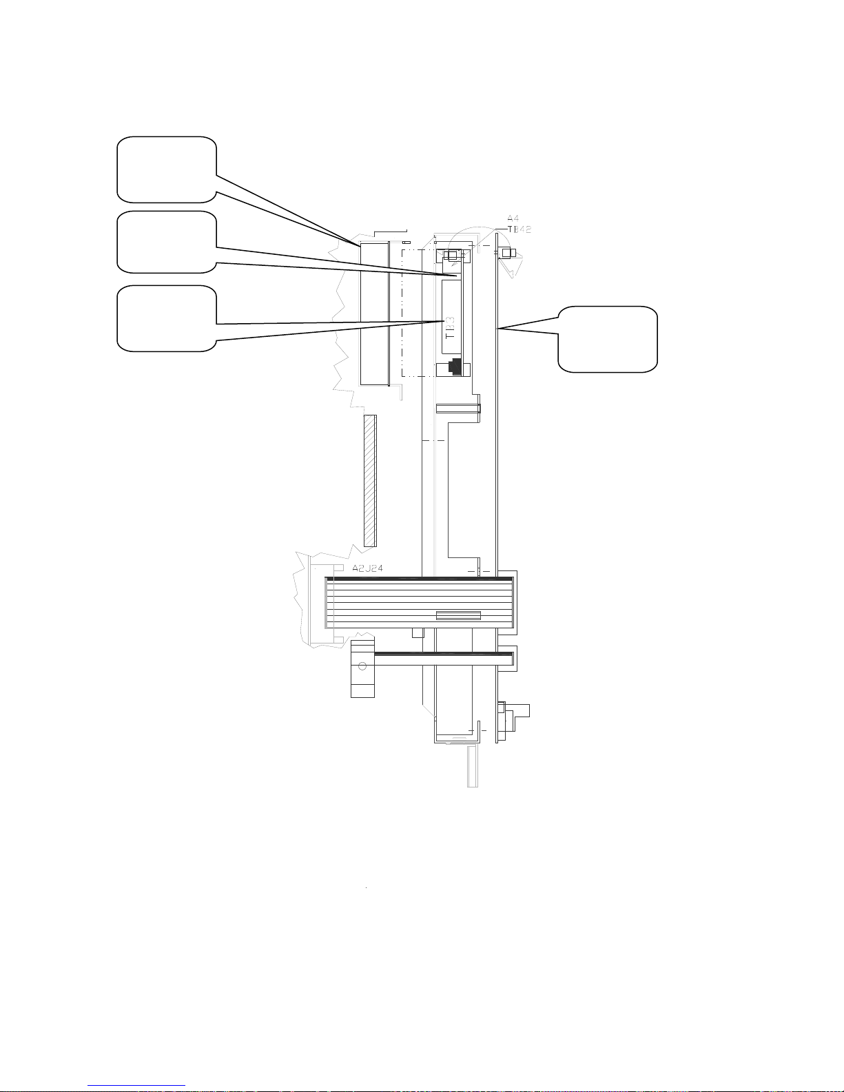
Introduction
POWER
SUPPLY
COVER
A4
POWER
SUPPLY
A4 TB3
A1 MAIN
CONTROL
PCB
Figure 4: Component Layout Right Side View
16
Page 19
Power Conversion Unit
Description
The Power Conversion Unit circuitry has three
major functions:
1. It converts three phase AC input power to
variable DC voltage for application to a
motor armature.
2. It converts motor generated DC power to
three-phase power to feed back to the line.
3. It converts single phase AC input power to
a variable DC voltage for application to a
motor field.
Two sources of power are required. A threephase power isolation transformer adjusts the
utility mains voltage to that required to operate
DSD 412 efficiently with the needs of the DC
hoist motor. 115VAC control power from a
separate source is used to power the low
voltage power supply, cooling fans, relay and
contactor logic.
Three phase input power is applied through
the AC line fuses to twin 6-SCR power bridges
for forward and reverse control. The PCU
microprocessor controls armature current
based on a reference received from the Drive
Control Unit microprocessor. Output from the
PCU microprocessor is sent to the Armature
Interface PCB, which produces the gating
signals for power SCRs. The SCR bridge
output is an adjustable DC voltage, which is
applied to the motor armature circuit. Power
circuit AC and DC measurement signals are
routed to voltage dividers on the Armature
Interface PCB, and scaled values are sent to
the PCU microprocessor. Armature current is
also measured and the feedback signal is
routed through the Armature Interface PCB to
the PCU microprocessor. An over current trip
function monitors this signal to initiate an
instantaneous static trip (IST) in the event of
excessive output current.
Single-phase power is also applied through the
AC line fuses to the Field Rectifier Module.
SCR gating signals from the PCU
microprocessor control the field rectifier SCRs.
A separate current measuring device is used
to monitor the DC current flowing to the motor
field. Additional connections allow for a
separate step-up or step-down transformer to
be used to power the motor field rectifier from
voltage mains different from that for the motor
armature.
Introduction
If optional dynamic braking resistors (DBR) are
present they are applied across the motor
armature to dissipate rotational energy
whenever the loop contactor is dropped out.
This helps to bring the motor to a stop even
when utility power is lost.
The largest component of the PCU is the SCR
bridge (Heat Sink Assembly). The heat sink is
an extruded aluminum structure that dissipates
the heat generated by the SCRs mounted on
the front surface (or between heat sink
sections, in large size power cubes). The
SCRs control the current to the motor armature
and in turn are controlled by the Armature
Interface PCB mounted in front of the SCRs.
Three input power line fuses are provided. A
DC Bus fuse protects the motor armature
circuit. A thermistor (and thermostat on some
ratings) senses heat sink temperature and
gives an over-temperature warning if an overtemperature occurs.
Access to the SCR Bridge is obtained by
opening the hinged door containing the Drive
Control PCB A1.
WARNING
Opening the hinged door with power applied to
the drive exposes dangerous voltage levels.
The hinged door should only be opened by a
qualified service technician, and only when the
power to the drive is turned off.
Hardware Descriptions
DSD 412 Power Supply PCB (A4)
Provides +5V, +15V, -15V, and +24V to the
control circuits and has fold-back current limit
protection. It also provides 115VAC
connections for the main contactor, motor
thermostat and fans.
Armature Interface PCB (A2)
Provides the interface circuitry between the
digital firing pulses generated by the Drive
Control PCB and the high current SCR gating
pulses controlling the armature current. It also
provides feedback signals from the power
section to the Drive Control PCB. A small
‘cube ID’ circuit board is attached to the
Armature Interface PCB to identify the ampere
capacity of the SCR power bridge to the PCU
processor.
17
Page 20
Introduction
SCR's
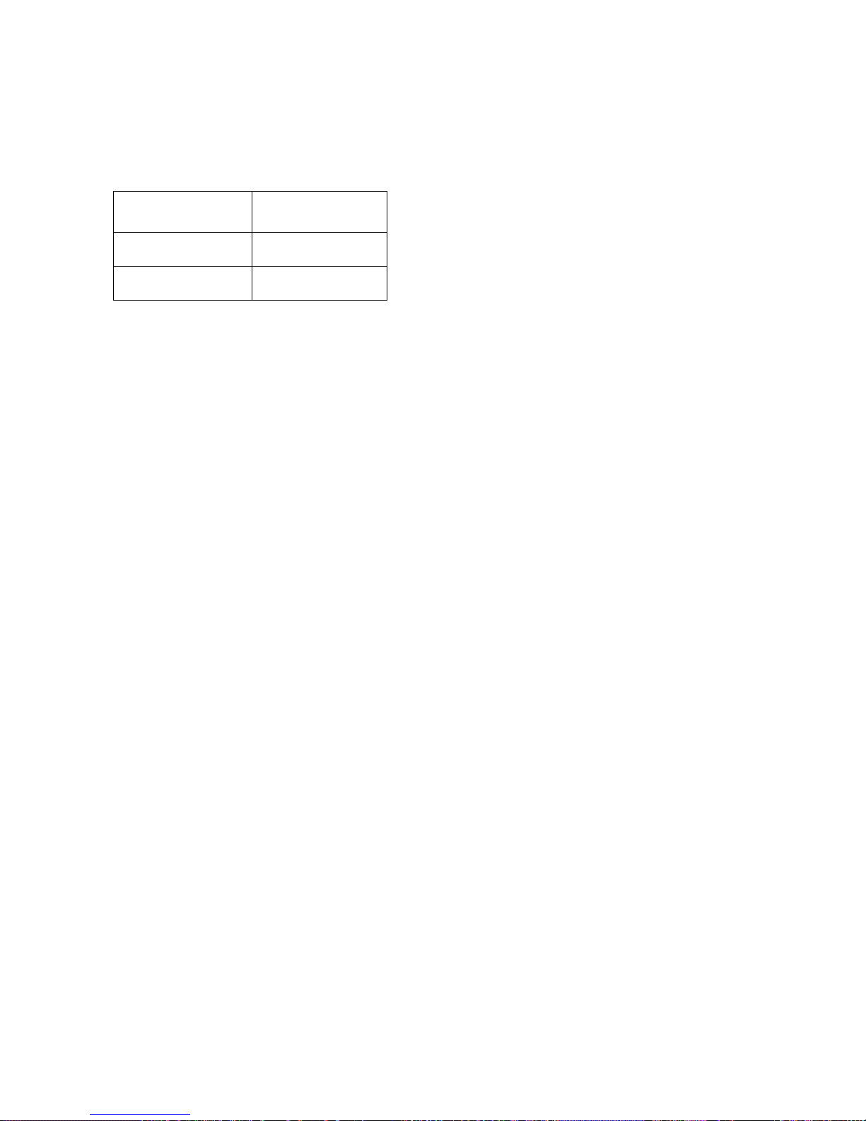
The drive uses different selections of doubler
packs or individual “hockey puck” SCRs
according to the horsepower ranges specified
below:
MOTOR ARMATURE
CURRENT
25A - 195 A Doubler
300 - 1285 A "Hockey Puck"
Field Interface PCB (A3)
Provides the interface circuitry between the
digital firing pulses generated by the Drive
Control PCB and transformer isolated SCR
gating pulses controlling the field current. It
also contains the field feedback circuitry and
the field SCR snubber circuit.
Cell snubber PCB (A5)
Is provided for SCR protection. These are
selected to work efficiently with utility line
impedance between 2 and 8 percent, including
that of the power input transformer.
Drive Control PCB (A1)
Mounted on the hinged door, this board
provides the microprocessors, memory and
support circuits needed to control drive
operation. Two control circuits are provided on
this PCB. One for controlling the Power
Conversion Unit (PCU), and another for speed
regulation and higher-level functions, called
the Drive Control Unit (DCU). These two
circuits communicate primarily through a DualPort Random Access Memory (DPRAM) IC
(integrated circuit) device.
Drive Control Unit
The major element of the DCU is a 16/32-bit
Motorola 68000 microprocessor. Random
Access Memory (RAM) provides memory
space to store values that are maintained only
SCR
TYPE
while power is on. Non Volatile Random
Access Memory (NVRAM) maintains drive
control parameters for the DCU when the
power is off. Two EPROM’s (Electrically
Programmable Read Only Memory) devices,
U39 & U40, contain the specific drive program
instructions for the DCU microprocessor.
Power Conversion Unit Control
The major element of the PCU control circuit
is a 16-bit Intel 80C196 microprocessor.
Again, RAM and EPROM devices, U13 & U14,
provide memory space and computer
instructions for the PCU. Any PCU parameters
that need to be maintained while power is off
are kept in NVRAM of the DCU and passed
through the DPRAM.
Local I/O
In an elevator application, the Local I/O
[Input/Output] allow the drive to have inputs
and outputs (I/O) such as RUN, STOP,
Encoder Feedback, Analog Reference Input,
Fault condition relay logic output, etc.
connected directly to the drive or passing
through a serial communications device.
Connection to the Local I/O is made via A1TB1
and/or the serial interface connection at
terminal point J1 mounted directly on the Drive
Control PCB (A1).
Front Panel Controls and Indicators
The upper right corner of the power cube cover
contains the operator controls and indicators.
Although accessible with the cover in place, all
of these components are part of the Drive
Control PCB (A1).
DRIVE RESET Button (S1)
Pressing this button causes the drive to clear
critical and non-critical faults and to restore
drive operation when faults are present. This
button will have no affect when the drive in
enabled.
18
Page 21

Introduction
Status LEDs
Located to the right of the RESET button is a
vertical strip of six light emitting diodes (LEDs):
READY — Indicates that the drive is ready to
run.
RUN — DC loop contactor is closed and drive
is controlling motor speed.
I LIMIT — Drive operation is demanding current
limit armature current.
OVERLOAD — Motor armature current is in
overload region. If lighted when the drive is
stopped, indicates that an over-load trip has
occurred.
E-STOP — Drive contactor safety interlock is
detected open. Drive will not run when this light
is on.
FAULT — Indicates that a declared drive fault
exists. The Fault/Error Code List defines what
conditions the drive will recognize as faults.
Standard Control Display Unit
The major part of the SCDU is a 4-1/2-digit
numeric LED display. Each of its four full digits
can display the values of 0 to 9 plus limited
alphabetic characters. The so-called half digit
can display only the value 1 and a plus or
minus sign. Underneath this display are a
green LED, labeled DATA, a red LED, labeled
DATA PEND, and a row of four push buttons.
The DATA and DATA PEND LEDs are used to
indicate the significance of the LED display
data, and the four push buttons (DATA/FCTN,
› [UP], › [DOWN], and ENTER) are used to
operate the SCDU. The functions and
capabilities of the SCDU are explained in
greater detail on page 25.
Non-Volatile RAM Protection
To the left of the four push buttons of the
SCDU there is a red LED labeled MEM
UNPROT. This LED is lit when the “protected”
portion of the non-volatile random access
memory (NVRAM) can be written to. The
switch labeled S3, which is located just under
the MEM UNPROT LED, determines
protection of the NVRAM. When this switch is
in the "ON" position, the NV RAM
UNPROTECTED LED is off and the protected
portion of the NVRAM cannot be written to.
This prevents setup parameters and other
important constants from being accidentally
erased or changed. When these parameters
need to be changed the switch can be moved
to the "OFF" position, removing the write
protection and causing the NV RAM
UNPROTECTED LED to be lit. Refer to the
section described as saving parameters.
The NV RAM PROTECTION switch should be
left in THE "ON" position (UN-PROTECTED
NV MEM LED OFF) to protect the NVRAM
during the critical power-up and power-down
periods.
19
Page 22
Introduction
Precautionary Statements
In addition to notes, the following types of
precautionary statements appear in this
manual.
IMPORTANT
A statement of conditions that should be
observed during drive setup or operation to
ensure dependable service.
CAUTION
A statement of conditions that must be
observed to prevent undesired equipment
faults or degraded drive system performance
WARNING
A statement of conditions that MUST BE
OBSERVED to prevent personal injury, death,
or serious equipment damage.
How To Contact Magnetek
For additional information contact any
Magnetek Representative or contact the DSD
412 Elevator Technical Support Staff at:
Magnetek Elevator Products
N50 W13775 Overview Drive
Menomonee Falls, Wisconsin 53051 USA
PHONE: 800 236-1705 (all numbers USA)
OR 262-252-6999
FAX: 262 790-4142
Magnetek Elevator Products – Europe
20 Drake Mews, Crownhill
Milton Keynes, Busck MK8 0ER UK
PHONE: +44(0) 1234 756036
FAX: +44(0) 1234 756037
See us on the web at www.elevatordrives.com
Or email us at [email protected]
20
Page 23
Installation
Installation
Pre-Installation Considerations
Receipt of Shipment
All equipment is tested against defect at the
factory. Any damages or shortages evident
when the equipment is received must be
reported immediately to the commercial carrier
who transported the equipment. Assistance, if
required, is available from your Magnetek
representative. Always refer to the order
number, equipment description, and serial
number when contacting Magnetek.
Unpacking Instructions
Open Carton and remove the OSB panel
located on top of the drive. Remove Foam
from carton. Lift drive out of box, grip ONLY
sheet metal chassis. Do NOT lift using the
door assembly or the Field Interface Board.
Unbolt drive from 2x4s.
Packing Instructions for Reshipment or
Storage
For long periods of storage, equipment should
be covered to prevent corrosion and should be
placed in a clean, dry, location. If possible,
equipment should be stored in its original
packaging. Periodic inspection should be
made to ensure that the equipment is dry and
that no condensation has accumulated. The
equipment warranty does not cover damage
due to improper storage.
The drive should be packed in its original
shipping container if it is required that it be
shipped. Not following the detailed instructions
outlined on page 110 will result in damage to
the drive. Refer to Packing Instructions on
page 110 for proper reshipment.
Selecting, Mounting and Wiring of the
Digital Encoder
Encoder Selection
A quality encoder is recommended for use with
the DSD 412 controller for speed feedback. The
encoder should be a two channel, quadrature,
zero speed type device with differential line
drivers. The DSD 412 drive supplies +5V power
for an encoder, however the encoder and
feedback signals may operate from another
source, up to 15 volts if desired. The Pulses per
Revolution count must be sufficient to provide an
adequate frequency feedback at very low
speeds, and yet not exceed 300 kHz (per
channel) at top speed. For most elevator
applications this target will be met when the
feedback frequency (per channel) is greater than
50KHz at contract speed. For gearless
machines, which have a base speed around
100RPM, a 10,000PPR encoder is a good
choice for direct connection to the motor shaft.
For geared machines, with motors running at
1750 or 1150RPM, 2500PPR encoder may be
used. Direct mounted hollow shaft encoders,
electrically insulated from motor shaft and motor
frame will yield the best results. The use of an
analog AC or DC tachometer is not supported by
DSD 412 elevator drives software or hardware.
Mounting
Proper mounting and alignment of the digital
encoder used for speed feedback is very critical
for the smooth operation of the DSD 412
controller. Even the slightest wobble of the
encoder shaft due to misalignment can cause
once-per-revolution torque pulsation that have
the potential of exciting natural rope resonance
frequencies.
Physical Installation
The DSD 412 Elevator Drive is air-cooled. The
lowest HP rated units are cooled by
convection; all other units are equipped with a
fan to ensure adequate airflow. Select a site
for installing the drive that is clean and well
ventilated. Maintenance will be minimized if
the drive is located in a clean atmosphere.
The standard drive is designed for vertical
mounting. Attach the drive to a cabinet panel
or other vertical structure using the mounting
holes provided at the back of the drive.
Ensure that the unit is level.
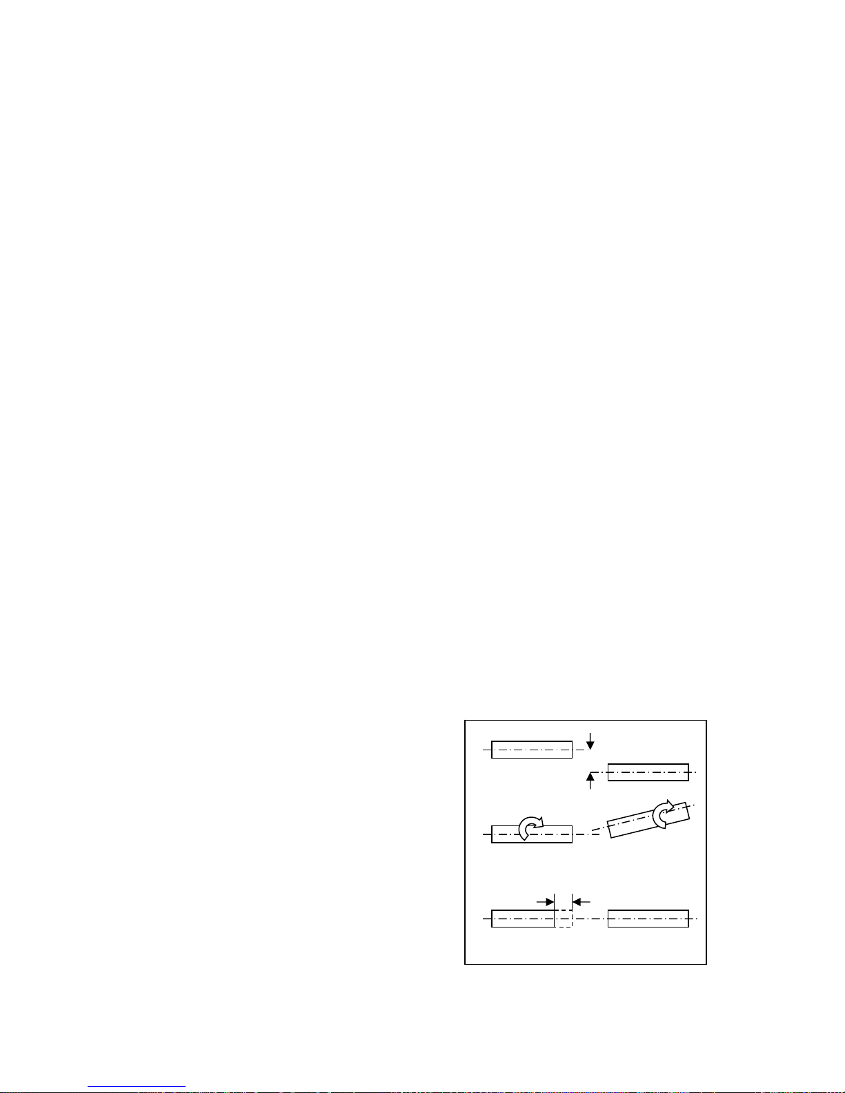
Non-concentric
Figure 5: Common Problems in Encoder
21
Input
Angular Misalignment
End Float
Mounting
Output
Page 24

Installation
The Magnetek recommendation for mounting
the encoder used for motor speed feedback is
to direct connect it to the motor shaft, usually
to the end opposite the drive end. Normally a
stub shaft is mounted in the end of the motor
shaft. The stub shaft must be absolutely
concentric (share the same center) with the
motor shaft, and have no angular
misalignment. The encoder is normally face
mounted to a bracket that is mounted on the
motor. A standard NEMA 56 “C” face adapter
bracket may be used, or a special fabricated
bracket may be designed and used. The
encoder should be mounted on the bracket
and positioned so that the encoder shaft and
the stub shaft are concentric and have no
angular misalignment or run-out. The coupling
should have electrical insulation to isolate the
motor shaft from that of the encoder. The
body of the encoder should be electrically
insulated from the motor frame.
An alternate method of mounting which has
been used in the elevator industry is to drive
the encoder with a rubber wheel that runs on
the brake surface of the sheave. This
approach may be satisfactory for many
applications, but it can introduce instability and
is not recommended:
1. Excessive bearing wear can occur in the
encoder due to the method of mounting and
holding the rubber wheel against the sheave.
2. Lack of concentricity of the measuring wheel.
3. The rubber wheel can develop a flat spot
when it sits idle for an extended time. This
goes away after a short time of operation,
but it can affect performance while it exists.
4. An angular misalignment can cause the
measuring wheel to skip or hop sideways,
causing a disturbance in the feedback signal.
Coupling
Almost regardless of the care used in
mounting the encoder, there is likely to be
some small amount of misalignment. A good
quality coupling between the encoder shaft
and the motor stub shaft can help avoid the
remaining problems due to shaft runout.
A good coupling will also offer some protection
for the encoder against end float, a condition
which exists in gearing on direction changes,
and which can be transmitted through the
motor. Again, the coupling should provide
electrical insulation between the motor and
encoder shafts.
Encoder Wiring
Wiring between the encoder and the DSD 412
drive should be shielded cable with 3 twisted
pairs. The pairs should be made up of A and
A, B and B, +5VDC and common. The shield
should be insulated from the encoder case,
and only connected at the drive end, to A1TB1
(6). This cable should be run in a separate
conduit between the encoder and the DSD
412. If the encoder must be connected to two
receivers (DSD 412 and car controller), the
cable should run from the encoder to the drive
(with this portion of the shield connected at the
drive) and then from the Drive to the car
controller (with the portion of the shield
connected to the car controller). Do not tie the
two shields together.
Exceeding Operating Specification
Do not exceed the operating specification of
the encoder/drive, in order to prevent the
encoder from providing incorrect data.
All encoders have inherent mechanical and
electronic limitations regarding speed. The
combination of several design factors including
bearings, frequency response of the
electronics, and PPR of the encoder, etc.
combine to determine "maximum operating
speed". Exceeding the maximum speed may
result in incorrect data or premature failure.
The encoder manufacturer can provide both
the electrical and mechanical encoder
specifications.
To determine the encoder's maximum
operating speed:
Step 1: Determine maximum electronic
operating speed in RPM.
60 x (kHz) response freq. Encoder
RPM
PPR Encoder
Step 2:
A. If the RPM calculated in Step 1 is less than
or equal to the encoder's maximum
mechanical RPM specification, then the
RPM calculated in Step 1 is the maximum
operating speed specification for this
particular encoder application.
B. If the RPM calculated in Step 1 is greater
than the encoder's maximum mechanical
RPM specification, then the maximum
mechanical RPM specification is the
maximum operating speed for this encoder
application.
22
Page 25
Step 3:
Compare the maximum operating speed as
determined in Step 2 above with the
application requirements.
To determine if the application exceeds the
operating specification of the DSD412:
Calculate the maximum pulses per
revolution (PPR) for this application
(using the HPV 900 frequency limit of 300
kHz and 120% of the application’s
top speed)
max PPR
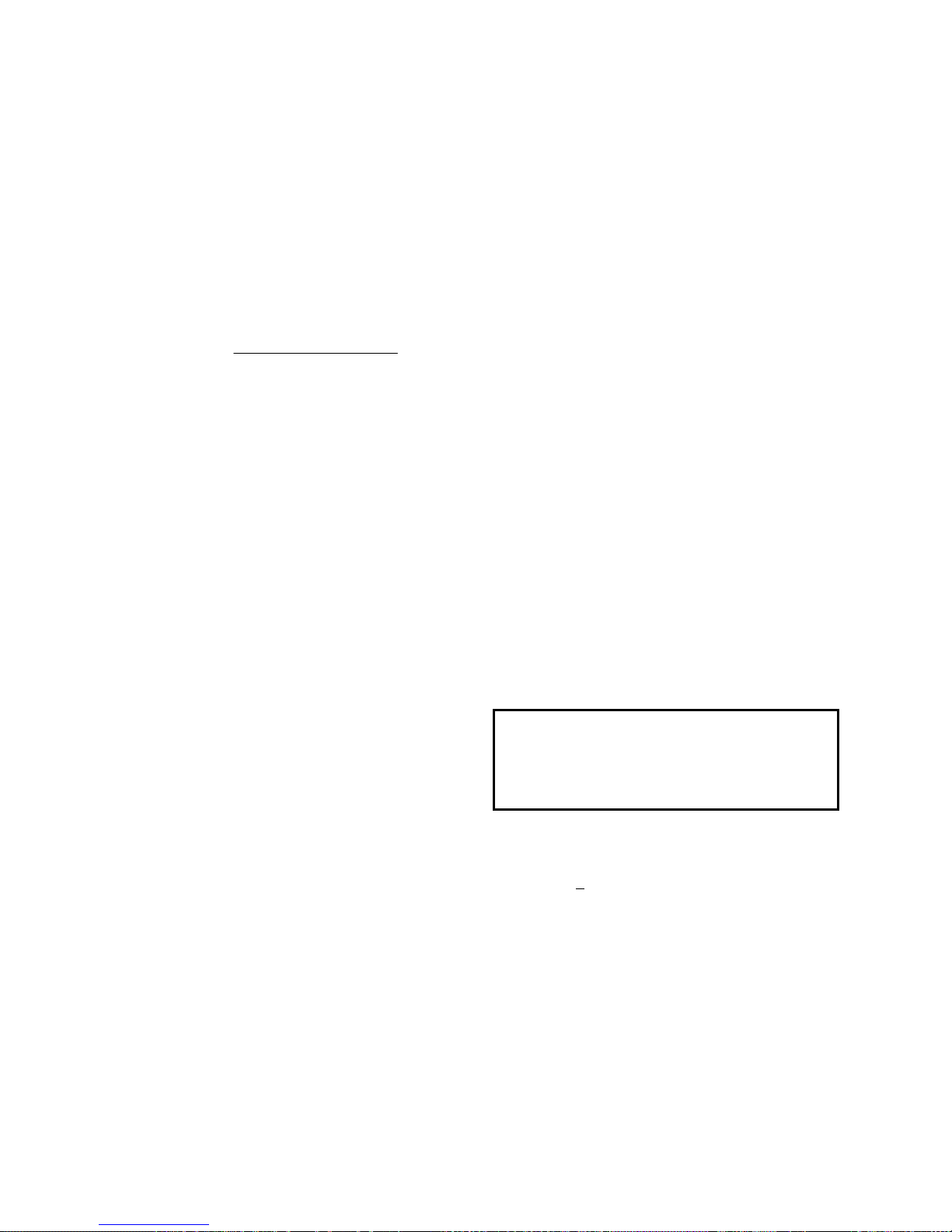
60*Hz 300,000
1.2*RPMn applicatiomax
Verify that the selected encoder’s PPR is
below the calculated maximum PPR
(PPRmax) for this application.
A common grounding stud or bus bar should be
provided within the drive enclosure cabinet,
electrically bonded to the metal enclosure.
A grounding wire should be provided directly
from the grounding terminal on the DSD 412
drive chassis to the common grounding stud.
A grounding wire should be provided directly
from the electrical sub-panel on which the DSD
412 drive is mounted to the common grounding
stud. Other electrical equipment, such as fans or
relay circuits may be grounded to the electrical
sub-panel.
A grounding wire should be provided directly
from the elevator motor frame to the common
grounding stud.
A grounding wire should be provided directly
from the power isolation transformer frame to the
common grounding stud.
A grounding wire should be provided directly
Electrical Hook up
Ensure that wire size and disconnect devices
conform to the installation contractor’s
drawings and to all applicable codes.
Power Connections
The three phase input power to the drive is
fuse protected internal to the Drive. However,
it is recommended to provide branch circuit
protection by means of a circuit breaker in
accordance with the National Electrical Code,
(USA) or as may be required by other local
electrical codes.
from building steel to the common grounding
stud.
If an armature circuit ripple filter is used, a
grounding wire should be provided directly from
the ripple filter inductor frame to the common
grounding stud. The sub-panel for capacitor
mounting within the filter should have a
grounding wire to the inductor frame.
The secondary side of the power isolation
transformer should remain un-grounded.
The low voltage circuit common should be
grounded by connecting A1TB1-43 or A1TB1-44
to A1TB11.
Signal Connections
All low power, low voltage wiring to the DSD
412 controller should be run separate from the
115VAC or higher power connections and the
DC motor armature and field connections.
These include:
Encoder Wiring
Speed Reference Wiring
Pre-Torque Reference Wiring
24 VDC Logic Inputs
Analog Outputs
Open Collector Logic Outputs
Rewiring these signals in shielded wire is
recommended to avoid noise pickup.
Grounding
The DSD 412 controller, the utility power
system feeding it and all other connected
power equipment should be grounded as
follows:
The facility power ground and grounding wire
sizes should comply with NEC, UL, CSA and
other applicable codes for power distribution
safety.
Pre-power Check
CAUTION
To prevent damage to the drive, the following
checks MUST BE performed BEFORE
applying 3-PHASE INPUT POWER to the
drive.
A. Inspect all equipment for signs of damage,
loose connections, or other defects.
B. Ensure the three-phase line voltage is
within +10% of the nominal input voltage
range of 150 to 525 VAC. The drive is not
sensitive to phase sequence. Input power
specifications are contained on the drive
nameplate or the drive system Schematic
Diagram.
C. Remove all shipping devices and relay
wedges. Manually operate all contactors
and relays to ensure that they move freely.
D. Ensure that all electrical connections are
secure.
E. Ensure that all transformers are connected
for proper voltage according to the Drive
system Interconnection Diagram.
Installation
23
Page 26

Installation
Drive Start up
Refer to the recommended connections shown
in the connection diagrams. Attach a voltmeter
across the 115VAC source for the control
power supply, at A4TB3-1 & A4TB3-7.
Apply the control and three-phase power and
verify that the control power is between 103
VAC and 126VAC. Then press the RESET
push button on the front of the power cube,
and observe the drive power-up sequence as
described below.
Drive power-up sequence
The power up sequence can be observed by
monitoring the Standard Control/Display Unit
(SCDU) on the front of the power cube.
1. First, all of the segments on the digital LED
display and all of the LEDs will light for
about 1 second.
2. Then the LEDs and display should
extinguish. The drive will perform internal
checks. The SCDU will display 'tESt' while
a self-test is being performed.
3. If the drive passes the self-test, then the
SCDU will display 'P-UP'. READY LED
will light.
Abnormal Display Conditions
Displays other than those mentioned above
may occur. The following is a list of
display conditions
actions necessary to correct the situation:
1. If no digits or LEDs light up, then check for
proper voltage between the 115 Vac
control power lines, or for blown 115 Vac
control power fuses, or for a defective
Control Voltage Power Supply in the power
cube.
2. If horizontal segment(s) of the SCDU
display are lit, then one or more phases of
the three-phase power are missing.
Measure and verify three phase power
input at the drive terminals. Check the
three-phase power fuses. See page 25 for
descriptions about the standard
control/display unit operation for more
detailed information about this test.
3. If the FAULT LED lights, and a fault code
appears on the SCDU, then refer to the
Fault/Error Codes List to see what caused
the fault and to find the correct solution. A
fault code is the letter 'F' followed by a
that may occur, and the
abnormal
number representing the fault. See
section describing standard control/display
unit operation for more detailed information
about fault reporting and clearing on page
25.
4. If the SCDU displays 'Prot', then the initial
checks found that the protected nonvolatile RAM (NVRAM) has not been
initialized. Move the NV RAM
PROTECTION switch to "OFF" in order to
allow the microprocessor to initialize the
NVRAM with preprogrammed default
values. Notice that the NV RAM
UNPROTECTED LED is now lit to indicate
the NV RAM PROTECTION switch
position. Next, press the RESET push
button. The drive will go through its power
up sequence again; however, this time it
will initialize the unprotected NVRAM and
load in factory supplied default parameter
values.
Fan Check
On drives with a blower motor (power bridge
fan), verify that the fans are working.
Verify Parameters
When the READY LED on the SCDU is lit, all
the selectable parameter data should be
checked and/or verified to the proper values as
follows:
1. VERIFY OR CHANGE EACH
PARAMETER VALUE for the particular
application and motor involved.
2. Perform PCU DIAGNOSTICS Function
998 should to verify armature and field
circuitry.
3. Perform SELF-TUNE PARAMETER TEST
Function # 997 to measure and verify
various motor parameters essential for
proper operation.
4. STORE PARAMETERS, Function # 994,
so that power can be removed and
reapplied without losing the entered
parameters.
5. Set the NV RAM PROTECT switch to the
protect position (UN PROT NV RAM light
is off) to ensure that set up data cannot be
corrupted.
6. Operate drive, using external control signal
inputs shown on the Interconnection
Diagram.
24
Page 27
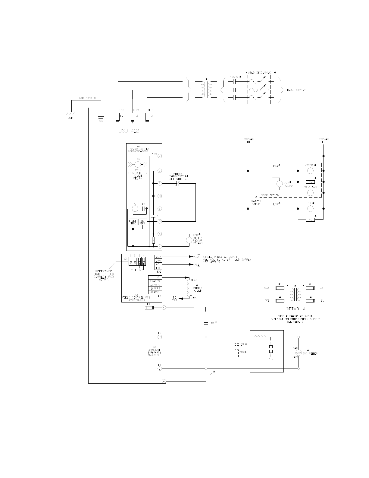
Interconnect Drawings
3-PH DRIVE
ISOLATION
TRANSFORMER
AS REQ'D
Interconnect Drawings
TB1(82)
+24VDC
TB1(78)
K4
SEE TABLE 5: RATED MOTOR FIELD
CURRENT RANGE
Figure 6: Power Signal Wiring
25
Page 28
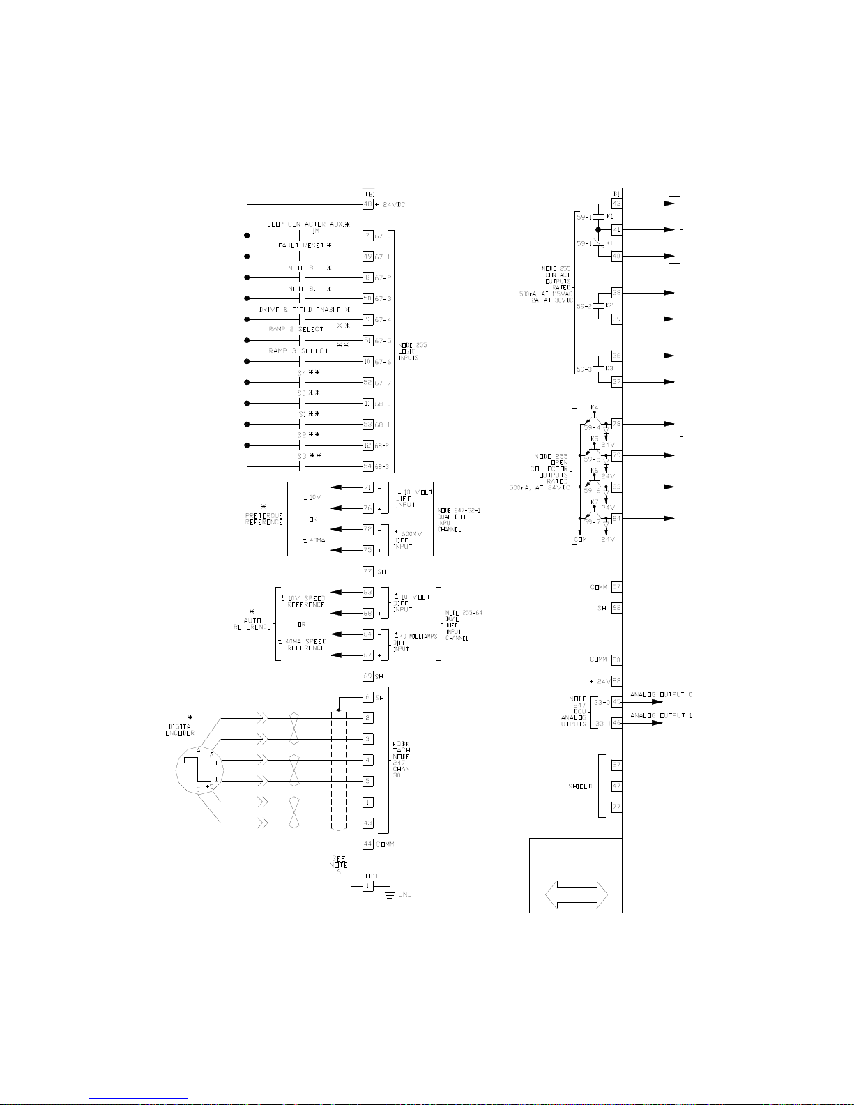
Interconnect Drawings
INPUT/OUTPUT
CONNECTIONS USING
ANALOG INTERFACE,
MODEL NUMBER
53STXXXX-3X00.
DRIVE OK/ NO
FAULTS RELAY
ENERGIZED WHEN NO
FAULTS ARE
PRESENT.
ALARM RELAY, MAY
BE ENERGIZED OR
DE-ENERGIZED ON
ALARMS. SEE TECH
MANUAL, FUNCTION
#182
PROGRAMMABLE
FUNCTION OUTPUTS.
REFER TO F#183 -
187
J2 RJ-12
CONNECTION
RS232 (PCDU
PORT)
DATA FLOW
Figure 7: Typical Analog Signal Wiring
26
Page 29
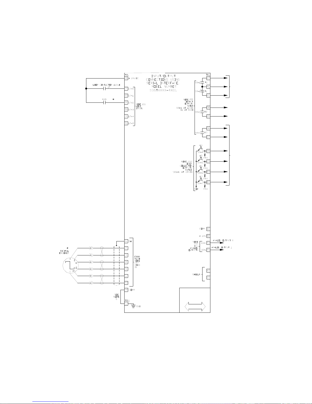
Interconnect Drawings
DRIVE OK/ NO
FAULTS RELAY
ENERGIZED WHEN NO
FAULTS ARE
PRESENT.
ALARM RELAY, MAY
BE ENERGIZED OR
DE-ENERGIZED ON
ALARMS. SEE TECH
MANUAL, FUNCTION
#182
PROGRAMMABLE
FUNCTION OUTPUTS.
REFER TO F#183 -
187
J1 DB9
CONNECTION
RS422
DATA FLOW
Figure 8: Typical Serial Signal Wiring
27
Page 30
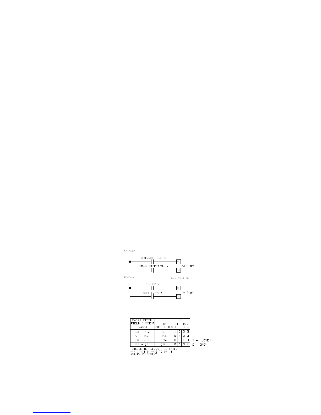
Interconnect Drawings
NOTES:
1. ITEMS NOT SUPPLIED BY MAGNETEK ARE
INDICATED WITH AN ASTERISK ( * ) OR
(**).
2. THE DC MOTOR CONNECTIONS SHOWN IS
FOR CCW ROTATION FACING THE
COMMUTATOR END. TO REVERSE ROTATION,
INTERCHANGE A1 AND A2 AT THE MOTOR.
DO NOT CONNECT SERIES FIELD (IF
SUPPLIED WITH MOTOR).
3. THE DRIVE IS PREWIRED TO HAVE THE
AC SUPPLIED TO THE FIELD RECTIFIER
DERIVED FROM L1 AND L2. IF A
DIFFERENT VOLTAGE IS REQUIRED MOVE
THE ORIGINAL WIRES FROM AC1 AND AC2
TO L1A AND L2A. THE ALTERNATE SUPPLY
SHOULD THEN BE BROUGHT INTO AC1 AND
AC2. THIS CONNECTION IS PHASE
SENSITIVE (SEE FIG 2.1a, DETAIL A).
4. ITEMS MARKED (**) ONLY APPLY WHEN
THE INTERNAL PRESET SPEED OPTION IS
USED.
5. ATTACH TO BUILDING GROUND.
6. INSTALL JUMPER FROM TB1(44) TO
TB11(1).
7. CONNECTION MUST BE MADE FOR
PROPER DRIVE OPERATION. IF MOTOR
THERMOSTAT IS NOT INSTALLED COMPLETE
WITH A JUMPER WIRE.
8. FUNCTION OF CONTACT INPUTS DEPENDS
ON PROGRAMMING OF FUNCTION #115. SEE
DIAGRAM THIS PAGE AND DESCRIPTION OF
F#115.
Figure 9: Power/Signal Wiring Notes
Figure 10: Run-Up/Run-Down vs. Run w/ Direction
Table 5: Rated Motor Field Current Range
28
Page 31
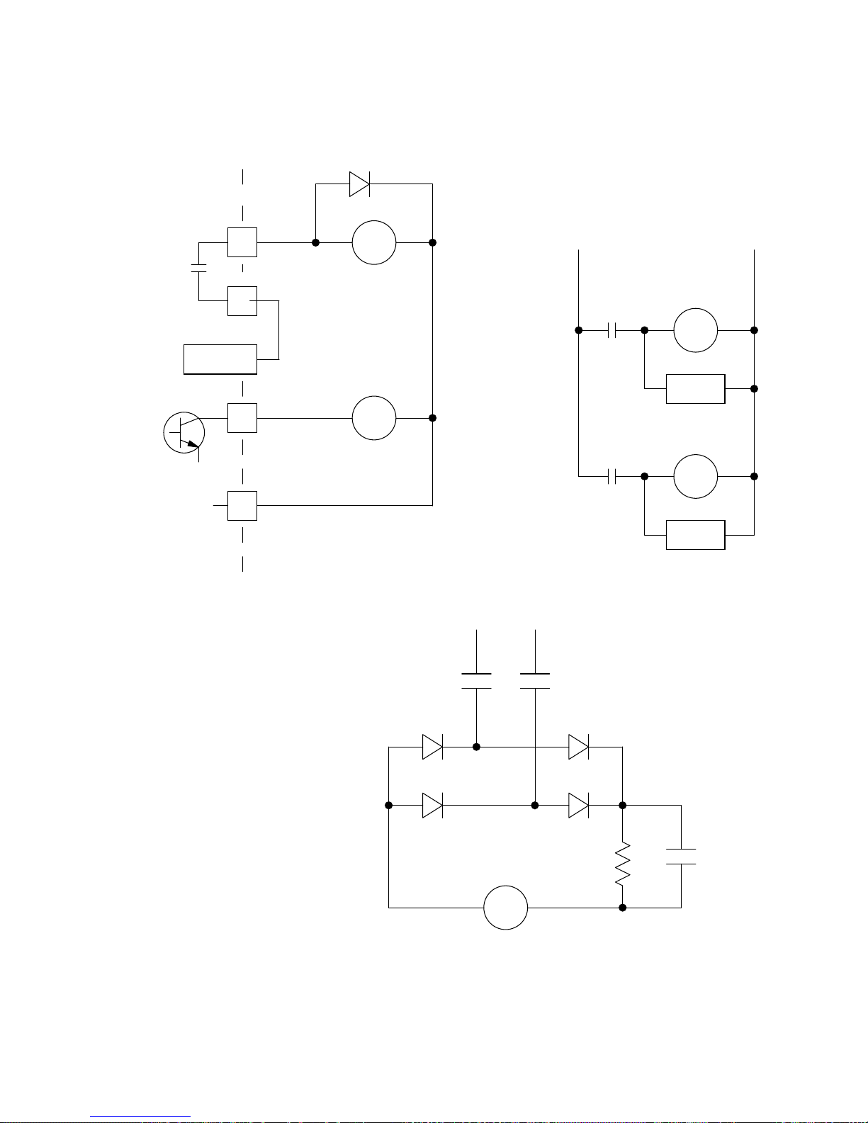
DSD 412
MAIN PCB
Interconnect Drawings
1N4002
36
K3
37
57 or 80COMM
K6
CONNECTIONS FOR
ELEVATOR BRAKE CONTROL
83
82+24 VDC
RELAY COILS 24VDC
LESS THAN 100 MA
K3x, 24VDC
(BRAKE PICK)
K6x, 24VDC
(LIFT & HOLD)
BRAKE VAC
SUPPLY SOURCE
BRAKE
LIFT
BRAKE
LIFT
CONTROL
K3x
K6x
115 VAC
POWER
BRAKE
PICK
R/C
BRAKE
LIFT
R/C
RECTIFIER
AS REQ'D
R-HOLD BRAKE
PICK
ELEVATOR BRAKE COIL
Figure 11: Drive Brake Control Feature
29
Page 32
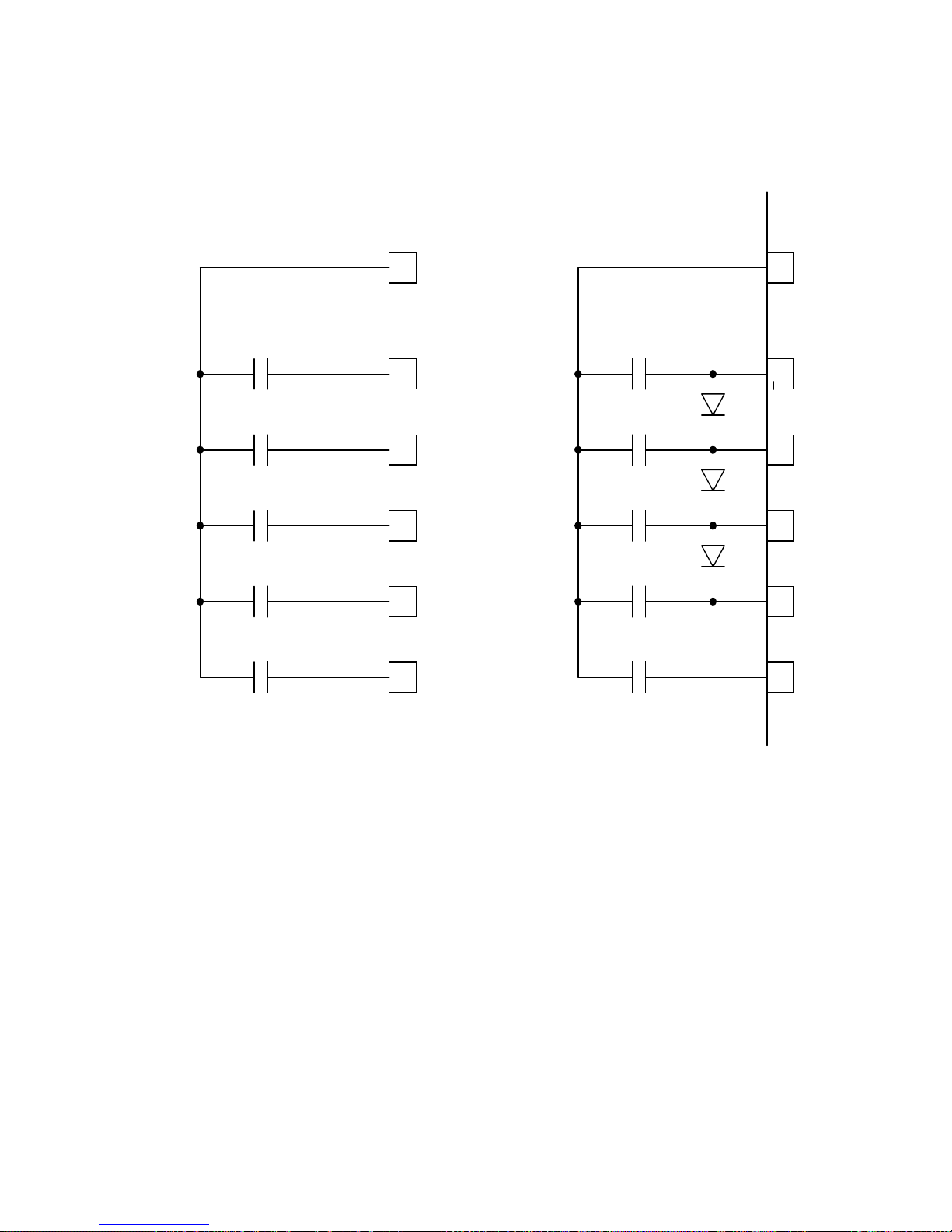
Interconnect Drawings
+24V
S4
S3
S2
S1
S0
PROGRESSIVELY
SCANNED RELAY LOGIC
ALTERNATE METHODS TO ACHIEVE PROGRESSIVE SPEED SELECT LOGIC
48
52
54
12
53
11
OR
+24V
48
S4
52
S3
54
S2
12
S1
53
S0
11
USING DIODES (1N4003)
TO YIELD PROGRESSIVE INPUTS
WITH SINGLE RELAY CLOSURES
Figure 12: Speed Select Logic Input Wiring
See detailed descriptions on pages 51 and 69.
30
Page 33
Standard Control/Display
Unit Operation
General
The Standard Control/Display Unit (SCDU) is
used to change and/or monitor various drive
dependent operational set points and perform
diagnostics for the Magnetek DSD Elevator
Drive. The SCDU is located in the upper right
corner of the Drive Control PCB and is
accessible through the power cube cover.
This Control/Display Unit is present on every
Magnetek DSD 412 Elevator Drive.
The SCDU consists of a 4-button keypad, a 41/2 digit numeric LED display, red and green
colored LEDs, an "NVRAM PROTECT" switch
(marked NV RAM PROTECTION on the power
cube cover), and a red LED that shows the
status of the "NVRAM PROTECT" switch.
Start-Up Operation
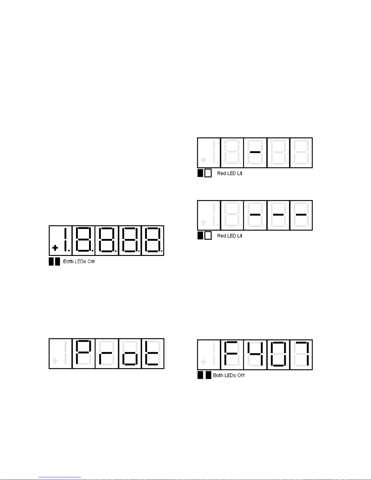
When power is first applied to the drive, all of
the segments on the 4-1/2-digit display will turn
on briefly in order to show that all are
functioning:
Standard Control/Display Operation
software in the drive is changed. C. The
NVRAM chip (U56) is changed.
After the LED lamp test has completed, the
drive software will now perform a fuse test on
each of the three line fuses. If any power
conversion fuse is open, the SCDU will
indicate this on its display. The SCDU display
is arranged in a similar manner to the physical
placement of the 3 line fuses in the power
cube. The middle segments of the three rightmost digits are used to indicate blown fuses.
For example, if the left-most line fuse is bad,
the SCDU will report it as follows:
If any two or more fuses are blown, the SCDU
display will be:
After this lamp test is completed, an internal
check is made to determine if the NVRAM
chips have ever been used before, or if the
EPROM’s are the same as before power
down. If not, the drive software will attempt to
load the defaults into the NVRAM chips. The
SCDU displays the word ‘Prot’ if the NV RAM
PROTECTION switch is in the position that will
not allow any updates of the NVRAM:
If the display shows ‘Prot’, it is necessary to
move the NV RAM PROTECT switch to the
"OFF" position and press the CPU RESET
button in order to load defaults into NVRAM
and restart the drive. Then set the NV RAM
PROTECT switch back to "ON". This ‘Prot’
message will only happen when: A. The drive
is powered up for the very first time. B. If the
The operator should then identify which fuses
have failed.
The drive will not operate unless all three line
fuses are functional. If the SCDU indicates a
bad fuse, power must be removed from the
drive, the fuse replaced and power reapplied.
After the drive has performed all three tests
(lamp test, RAM test, and fuse test), the SCDU
displays one of two final messages. If there
are any faults present at this time, the SCDU
will display a Fault code. The display will be
similar to:
where the leading ‘F’ indicates a fault and the
3 digits following the ‘F’ indicate the fault
number. If however, there are no faults
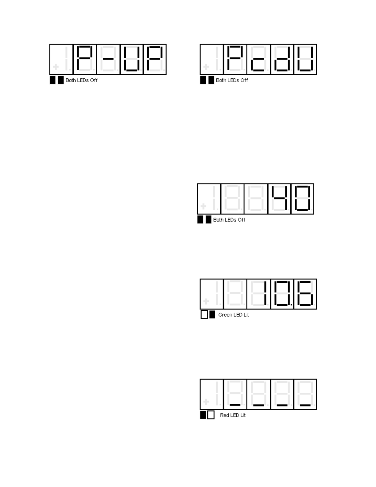
present, the SCDU displays the normal powerup message:
31
Page 34
Standard Control/Display Operation
This ‘P-UP’ display will remain on the SCDU
until a key is pressed or a fault occurs.
After Power-Up
After the drive has powered up and the SCDU
display is showing ‘P-UP’ or a fault number, it
can be used to enter new parameters, monitor
drive operation, and/or perform certain drive
diagnostics. Every operation that the SCDU
can perform is called a ‘function’. There may
be up to 1000 functions defined within the
DCU.
All SCDU functions have at least 2 levels, and
some functions use 3 levels. The two colored
LEDs below the lower left corner of the 4-1/2digit display are used to indicate which level of
a particular function the SCDU is currently at.
The top level of the SCDU operation is called
the "Function" level. The two colored LEDs
are off when the SCDU is in the "Function"
level. The ▲ or ▼keys are used to select a
function number to be accessed while at this
level. The ▲ key increments the function
number in the display while the ▼ key
decrements it. The SCDU will ramp the
displayed function number when the ▲ or ▼
key is pressed and held for 1/2 second or
longer.
The DATA/FCTN key is used to toggle
between the “Data” level and the “Function”
level. Press the DATA/FCTN key when the
desired function number is in the display. At
this point, the SCDU leaves the "Function"
level and enters the "Data" level. Note that the
green LED is now lit. This operation is
consistent for every function on the SCDU,
although the data actually displayed while the
LED is GREEN is function-number specific.
Examples of every type of SCDU function are
given in subsequent sections. All function
numbers are shared between the SCDU and
the PCDU (Portable Control/Display Unit).
There are some functions, however, that can
only be performed with the PCDU. When such
a function number is selected on the SCDU
and the DATA/FCTN key is pressed, the
SCDU’s display will change to:
Changing Parameter Functions
SCDU functions are used to modify and/or
display setup points that the drive needs for
operation. Items that would typically fall into
this category are functions such as Accel
Times, Regulator Gains, Rated Speed and any
other parameters. The following steps show
how to modify a given parameter via the SCDU
display.
1) Use the ▲ and ▼ keys to select the
function number to be accessed. The two
colored LEDs remain off during this step. For
example, if #040 is chosen:
2) Press the DATA/FCTN key to enter the
"Data" level for this function number. The
green LED is lit to indicate that the number
being shown is the current actual value for this
parameter. For example, if Function # 40 is
currently set for a value of 10.6, it will be
displayed as:
3) Use the ▲ and ▼ keys to ramp the number
in the SCDU display to the desired value.
Note that the red LED is lit to indicate that the
value being displayed is NOT the actual value,
but rather is in the process of being changed.
Each parameter has an upper and lower limit.
The following display will occur when the lower
limit is exceeded:
Similarly, if the upper limit is exceeded, the
SCDU displays:
32
Page 35
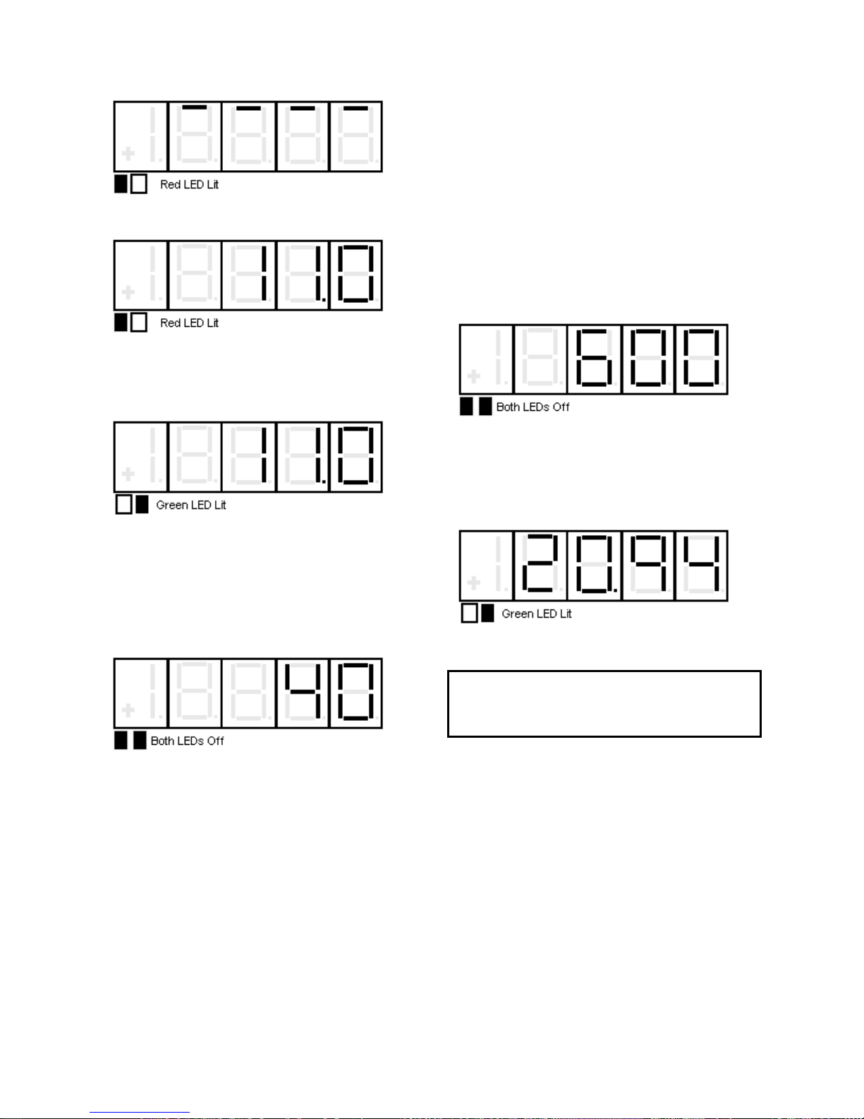
The SCDU display will increment from ‘10.6’ to
‘11.0’ if the ▲ key is pressed 4 times:
4) Press the ENTER key to transfer the value
in the SCDU display to the actual value used
by the drive. Note that the green LED will now
light to indicate that this value is now the actual
value for this parameter:
If the ENTER key is pressed while the display
is indicating that the upper or lower limit has
been exceeded, the display will change to the
appropriate limit and the green LED will light.
5) Press the DATA/FCTN key to put the
SCDU back into the "Function" level. As with
the example above, the SCDU display will be
similar to:
Standard Control/Display Operation
Viewing Monitor Functions
Items that would typically fall into this category
are Speed Feedback, Armature Current and
Armature Voltage.
To view one of these values, it must have been
previously programmed in the drive. The
following steps show how to display a given
value on the SCDU display.
1) Use the ▲ and ▼ keys to select the
function number (between 600 and 799) to be
accessed. The two colored LEDs remain off
during this step. For example, if 600 is
selected, the SCDU display will be:
2) Press the DATA/FCTN key to enter the
"Data" level for this function number. The
green LED is lit to indicate that actual data is
currently being viewed. If the data for Function
# 604 is currently at 20.94 for example, the
SCDU display will change to:
The SCDU’s display is updated immediately if
the value for the selected function changes.
All changes made become active values upon
pressing the ENTER key. They remain active
until the next reset, or until the drive is
powered down. When the drive is reset or
powered up the value reverts to the value
stored in NVRAM. If changes are to be
permanent, use Function # 994 to save the
changed value in NVRAM.
Due to programming considerations it may be
possible to access a value that cannot be
changed. In this case the CDU function will
proceed as described until the ENTER key is
pressed to change the value. In this case the
value will simply ignore any requested
changes and remain the same.
NOTE
Values displayed with these function numbers
cannot be modified.
Error Reporting
The drive has two methods available to report
errors and faults. Each error condition may
utilize ONE OR BOTH OR NEITHER of the
reporting methods.
The most conventional method is called ‘fault
recording’. If this method is enabled for a
particular error, the red FAULT LED and a
unique fault code number will appear on the
SCDU at the moment when the error occurs.
Each occurrence of a fault is recorded in an
area in RAM called the Fault List. The Fault
List stores the 16 OLDEST faults and stops
recording faults as soon as the 16th fault
occurs. This list is erased when the drive is
33
Page 36
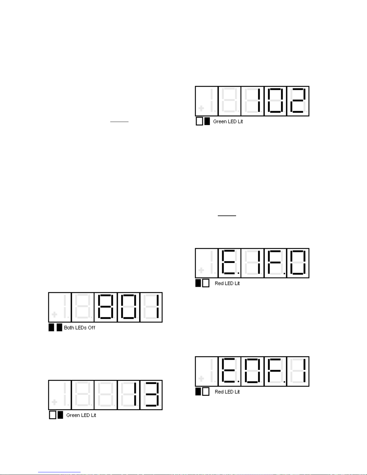
Standard Control/Display Operation
powered down or reset. Whether or not the
drive stops or continues to run is dependent on
the way the particular fault is implemented.
Most standard faults are set up so that the
drive will stop if a fault occurs. Faults stored
on the Fault List will appear when viewing
Function # 0.
The second method for error handling is called
‘error recording’. Error recording differs from
fault recording in three respects:
1. The error condition will not be shown on
the SCDU or the red Fault LED.
2. The error list stores the 16 most recent
errors and always overwrites the oldest
error with the newest error.
3. This list is maintained in battery-backed-up
RAM and is retained when the drive is
powered down or reset. Operation of the
drive is totally independent of whether
error recording is enabled or not.
4. The Errors List may be viewed at Function
# 800.
Function # 801
Used to display or alter the Fault & Error
Disposition List. This list is consulted any time
an error condition occurs to determine whether
it should be reported as an error, a fault, or
both. The process for changing the entry in
the disposition list for a particular error using
the SCDU is as follows:
3) Use the ▲ and ▼ keys to select the error
code entry in the Disposition List that is about
to be changed/viewed. For example, if the
disposition for error code 102 (Numeric
Underflow) is to be modified, press the key
until the SCDU display changes to:
4) Press the ENTER key when the desired
error code is displayed on the SCDU. The red
LED now lights, and the SCDU display
changes as well to a format of ‘E.xF.y’.
The ‘E’ and ‘F’ are abbreviations for Error and
Fault respectively. The ‘x’ and ‘y’ will be either
‘1’ or ‘0’ to indicate which list will record the
error. For example, if the display is ‘E.1F.1’,
the error is recorded in both lists. If the display
is ‘E.0F.1’, the error is recorded in the fault list,
but not in the error list. If the display is
‘E.0F.0’, neither list records the error. In the
example above, the factory set default
disposition for a numeric overflow F#102 is to
record the error in the Error List, but not in the
Fault List. In this case, the SCDU display is:
1) Use the ▲ and ▼ keys to select
function number # 801 from the function level.
The two colored LEDs remain off during this
step.
2) Press the DATA/FCTN key to enter the
"Data" level for Function #801. The green LED
will light and the error code last modified, with
Function #801, will be in the SCDU display.
The SCDU displays error code #13 (illegal
instruction) initially:
5) Press either the ▲ or ▼ key repeatedly to
change the numbers after the ‘E’ and ‘F’ from
‘1’ to ‘0’ and vice-versa. Starting from no
declarations, the displays are: ‘E.0F.0’,
‘E.0F.1’, ‘E.1F.0’, and ‘E.1F.1’. For example, if
the disposition for this error should be changed
so that it is NOT recorded in either the Fault or
Error list, press the ▼ key once so the
display changes to:
This display indicates that the Numeric
Underflow error will now be recorded in the
Fault List, but not in the Error List.
34
Page 37
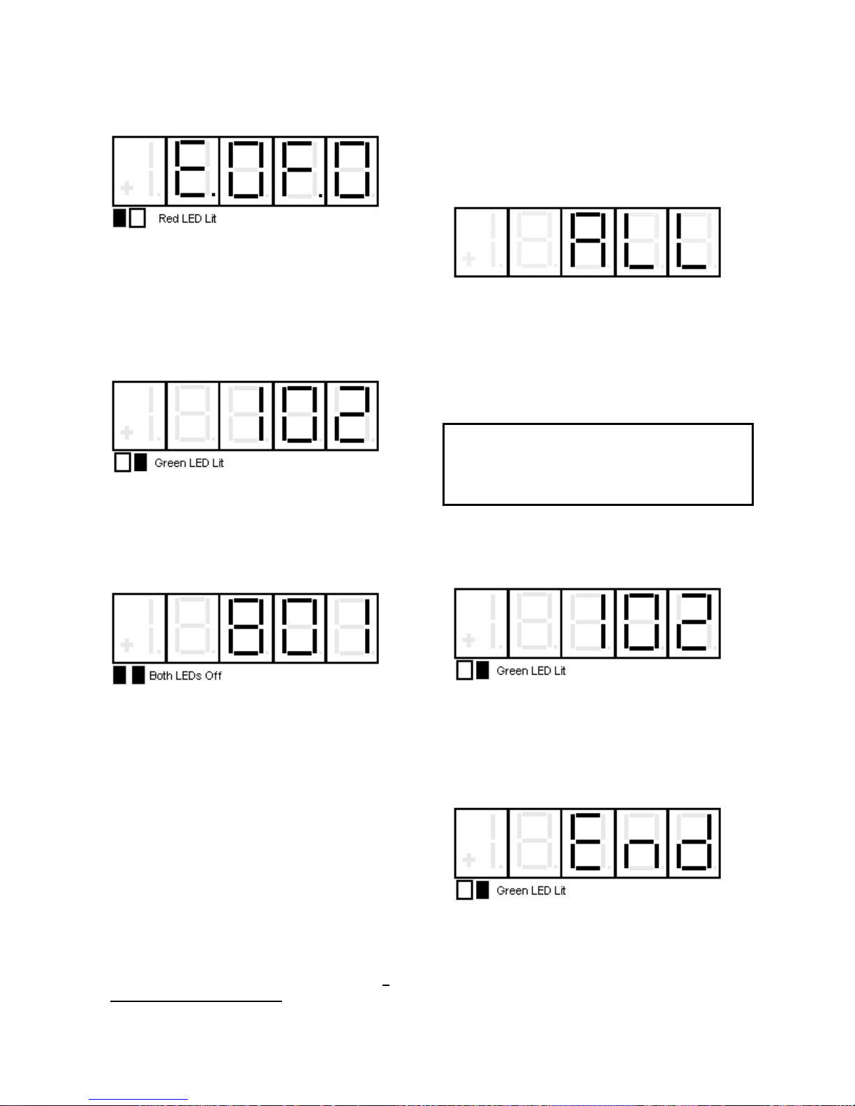
Pressing the ▼ key once more will change
the display to:
This is the desired status for the new
disposition of the Numeric Underflow error,
which is to not report it to either the Fault or
Error List.
6) Press the ENT key when the new
disposition code is in the display. At this point,
the green LED will light, and the SCDU
displays the error code again:
Standard Control/Display Operation
2) Press the DATA/FCTN key to enter the
"Data" level for this function. The green LED
is now lit to indicate that the fault codes
currently in the Fault List are being displayed.
The very first display at this point is the word
'ALL':
The SCDU display always displays the fault
code that will be removed if the ENTER key is
pressed. If the ENTER key is pressed at this
time, every fault currently in the Fault List will
be removed from the list.
Each fault in the Fault List can be shown on
the SCDU display and optionally cleared.
IMPORTANT
The ▲ and ▼ keys can now be used to
select another error code to be modified, as in
step 3.
7) When all changes in the Error Disposition
List are finished, pressing ENTER key will exit
back to the function level:
Fault Display/Clear
The drive stores the first 16 faults that have
been reported to the Fault List, Function # 0.
Once the Fault List is filled with 16 faults, it will
not accept any more entries. The data in this
buffer is not retained when the power is lost.
Each time a fault condition occurs, and its
entry in the Disposition List is set to record
also in the Fault List, the new fault is placed on
the list, provided the list is not full.
Function # 0
Reserved for viewing the Fault List. The steps
to view the Fault List are as follows:
1) Use the ▲ and ▼ keys to select
Function # 0. The two colored LEDs remain
off during this step. Note that simply pressing
the ▲ key once can access this function, if
the SCDU display is ‘P-UP’.
The process of clearing a fault from the Fault
List DOES NOT actually clear the condition
that caused the fault.
To view the first fault on the list, press the ▲
key. If there is a Numeric Underflow fault 102
is on the Fault List, for example, the SCDU
display will change to:
The contents of the Fault List may be
examined by using the ▲ and ▼ keys.
The ▼ key moves down the fault list while
the ▲ key moves up the fault list. The first
fault in the list is the first fault actually
declared. The SCDU displays the word 'End'
after the last fault has been displayed:
Error Display
The drive is able to store the most recent 16
errors that have been reported to the Error
List. This list is constantly updated, with the
newest error overwriting the oldest in the list.
35
Page 38
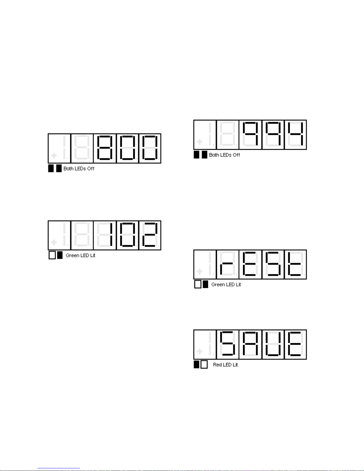
Standard Control/Display Operation
This list is held in battery-backed-up RAM
(NVRAM), so it is retained when power is lost.
Each time an error condition occurs, and if its
entry in the Disposition List is set to allow
recording in the Error List, that new error is
placed in the list.
Function # 800
Reserved for viewing the Error List in NVRAM.
The steps to view the Error List are as follows:
1) Use the ▲ and ▼ keys to select
Function # 800. The two colored LEDs remain
off during this step.
2) Press the DATA/FCTN key to enter the
"Data" level for the view error function. The
green LED is now lit to indicate that an error
code is currently being viewed. If the error in
this slot is a Numeric Underflow fault 102 for
example, the SCDU will display:
perform transfers between the NVRAM
parameter list and the active parameter list.
Function # 994 is used to perform the transfer
of data between the NVRAM and active
parameter lists. The process for copying data
to or from the NVRAM parameter list is as
follows:
1) Use the ▲ and ▼ keys to select
Function # 994 from the function level. The
two colored LEDs remain off during this step.
2) Press the DATA/FCTN key to enter the
"Data" level for Function # 994. The green
LED is now lit to indicate that this function is
currently being accessed. It is possible to
SAVE the current active parameters in RAM to
the NVRAM parameter list, or to RESTORE
the current parameters from the NVRAM
parameter list to ACTIVE RAM. Note that a
RESTORE is the same operation that occurs
inherently every time the drive is powered up.
Upon entering the data level for this function,
the SCDU displays:
Other errors currently in the Error List can be
viewed by pressing the ENTER key to display
the Error Code again, then use either the ▲
or ▼ key to move to the next slot in the list.
The procedure outlined above should be
repeated as necessary to view the Error Code
number for other errors in the Error List.
Non-Volatile Ram Access
Every parameter that the drive uses has three
separate areas in memory associated with it.
There is a factory-set default value for each
parameter which is stored in the “read only”
EPROM chips. There is an area in the active
RAM which the drive uses while it is running.
There is also an area in NVRAM reserved for
each parameter. The values in the NVRAM
area are copied to the active RAM every time
the drive is powered up or the reset button is
pressed. This split level approach makes it
possible to return to the last set of ‘stable’
parameters in NVRAM if some errors are
made during fine-tuning of the active drive
parameters. The purpose of this function is to
The ▲ and ▼ keys can be used to toggle
between the above display, which indicates a
pending RESTORE operation, and the
following display, which indicates a pending
SAVE:
Note that as soon as either the ▲ or ▼ key
is pressed, the red LED will light.
3) Press the ENTER key to actually perform
the transfer of data. If ENTER is pressed while
'SAVE' is displayed, the SCDU display may
change to:
36
Page 39
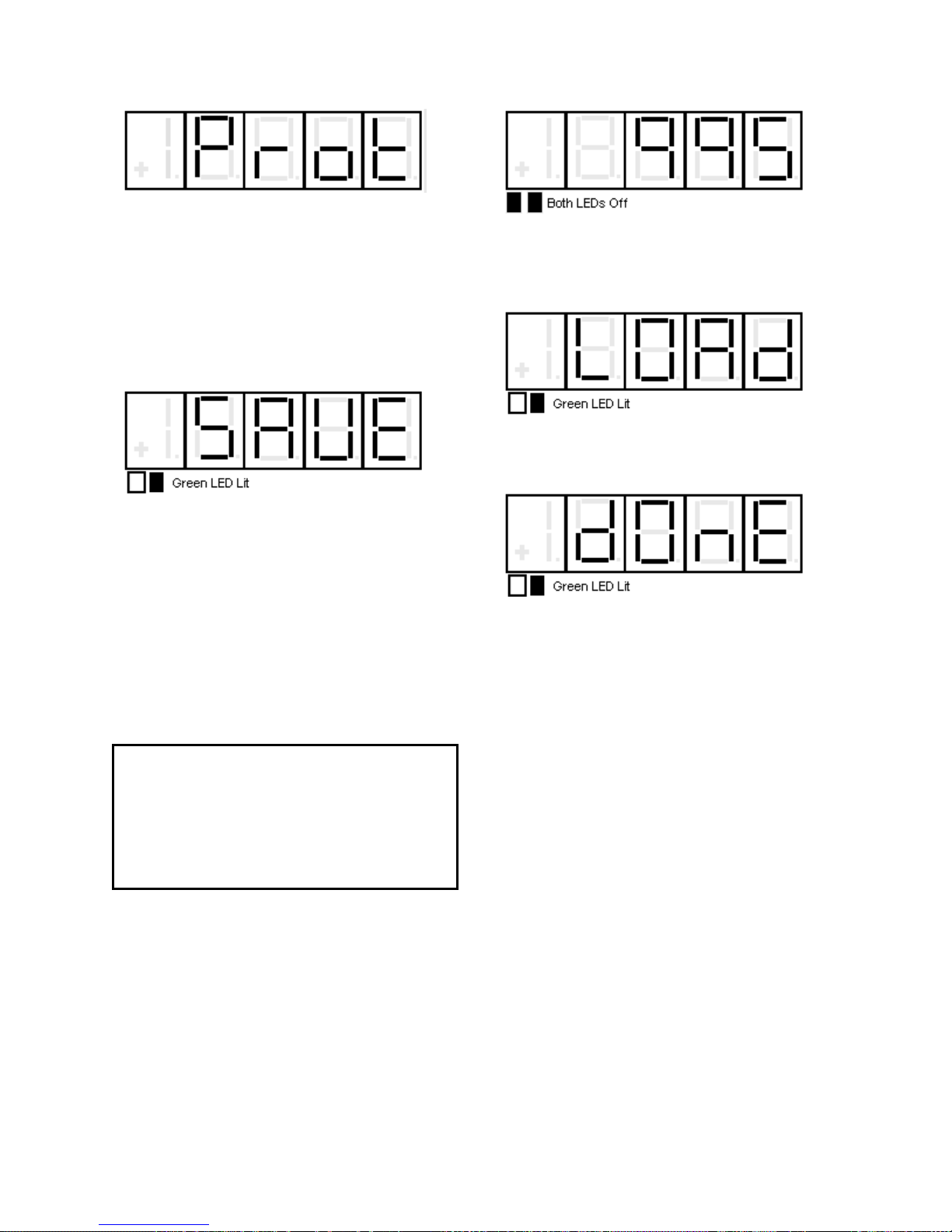
This display means that the NV RAM
PROTECTION switch is in the incorrect
position preventing writes to the NVRAM.
Move the switch to the "OFF" position, press
the DATA/FCTN key, and start over from step
2.
If the SAVE or RESTORE operation was
successful, the green LED will light. For
example, if a SAVE were performed, the
display would be:
Load Default Function
Every parameter in the drive has a factory-set
default value that is loaded when the drive is
powered up for the very first time. These
default parameters may not be optimal values
for the drive when actually running, but they
will generally allow the drive to function. It is
possible to reload these default parameters
with Function # 995 of the SCDU. A re-load
of the defaults would generally be done when
the drive is operating erratically and it is
suspected that one or more parameters were
improperly set.
CAUTION
Use of the LOAD DEFAULTS function will
overwrite EVERY parameter currently being
used by the drive with the factory set default
for each parameter. There is no way to restore
parameters to their previous value once this
function is used.
Function # 995 is used to perform the transfer
of data from the default parameter list to the
ACTIVE RAM parameter list. The process for
accessing the Load Defaults Function is as
follows:
1) Use the ▲ and ▼ keys to select
Function # 995 from the function level. The
two colored LEDs remain off during this step.
Standard Control/Display Operation
2) Press the DATA/FCTN key to enter the
"Data" level for Function # 995. The green
LED is now lit to indicate that this function is
currently being accessed. The SCDU will now
display:
3) Press the ENTER key to actually perform
the Load Defaults transfer. After the transfer
has completed, the SCDU displays the word
'dOnE':
4) A cycling of control power is then necessary
to implement the default settings onto the
display.
Self Tune Function
The DSD 412 Elevator drive has a built-in
current regulator SELF TUNING Function #
997. When activated, this feature measures
total motor armature circuit resistance,
inductance including wiring, and the field L/R
time constant. The drive then uses the
measured value in conjunction with the
parameter entered for “CROSSOVER
FREQUENCY” to calculate integral and
proportional gains for the current regulator and
to set the field regulator gains properly. After
running the Self Tune Parameter
Measurement function, the values for armature
resistance and armature inductance are stored
in NVRAM. It is important to note that it is
possible to override the values that have been
dynamically calculated for Armature
Resistance, Armature Inductance, and Field
L/R Time Constant by the “USE SELF-TUNE”
item in the parameter menu (Function # 2).
The dynamically calculated values are used if
“USE SELF-TUNE” is set to “ON” while the
manually entered values (entered in
37
Page 40
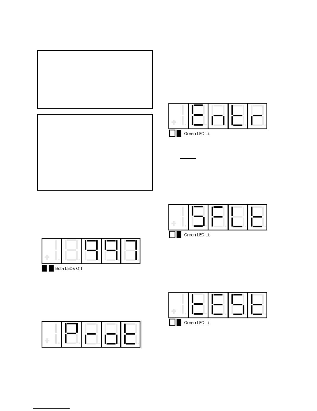
Standard Control/Display Operation
parameter’s 4, 6, and 51) are used if this item
is set to “OFF”.
NOTE:
Armature current is circulated through the
armature circuit during parts of the PCU
Parameter Measurement function. The PCU
will reduce the field current to zero on motors
with a shunt field in order to minimize motor
rotation. If the PCU detects significant motor
voltage during the test, the PCU parameter
measurement function will abort.
Ripple Filter Consideration
It is important to note that when applying a
LRC output filter (Ripple Filter), the drive
performance will be affected. For this reason,
it is necessary to run the SELF-TUNE test with
the output configuration that will be used. For
example, if the filter is used with the capacitor
fuse installed, then the SELF-TUNE test must
also be run with the filter fuse installed. If the
capacitors are not needed, then the fuse
should be pulled and the SELF-TUNE test
should be run with the fuse pulled.
The process for accessing the PCU
PARAMETER MEASUREMENT function is as
follows:
to the "OFF" position, and press the
DATA/FCTN key again. The SCDU will jump
to step #3 when the NVRAM PROTECTION
switch is in the correct position upon entering
this function.
2) The SCDU displays the word ‘Entr’ to
prompt the user to press the ENTER key as
further confirmation that the PCU parameter
measurement function is about to be
performed:
3) Press the ENTER key to actually start the
PCU Parameter Measurement function. The
PCU will not begin the measurement routine if
a SEVERE PCU FAULT exists. The PCU will
declare a SEVERE FAULT under several
conditions including an IST fault, power supply
failure, line sync loss, low line, or DCU failure.
If a SEVERE FAULT exists when the PCU
starts the parameter measurements, the
SCDU displays:
1) Use the ▲ and ▼ keys to select
Function # 997 from the function level. The
two colored LEDs remain off during this step.
1) Press the DATA/FCTN key to enter the
"Data" level for Function # 997. The green
LED is now lit to indicate that this function is
currently being accessed. The SCDU displays
the word 'Prot' if the NV RAM PROTECTION
switch is in the position that will not allow any
updates to the NVRAM:
If the ‘Prot’ message appears, press the
DATA/FCTN key to return to the "Function"
level, move the NVRAM PROTECTION switch
Severe faults can only be cleared by pressing
the reset button on the Drive Control PCB, by
cycling power to the drive, or by replacing the
bad component if applicable. The SCDU
displays the word ‘tESt’ while it is performing
the parameter measurements and there were
no SEVERE FAULTS when the ENTER key
was pressed:
4) Press the DATA/FCTN key to exit the
PCU parameter measurement routine and
return to the "Function" level. The SCDU
displays:
38
Page 41
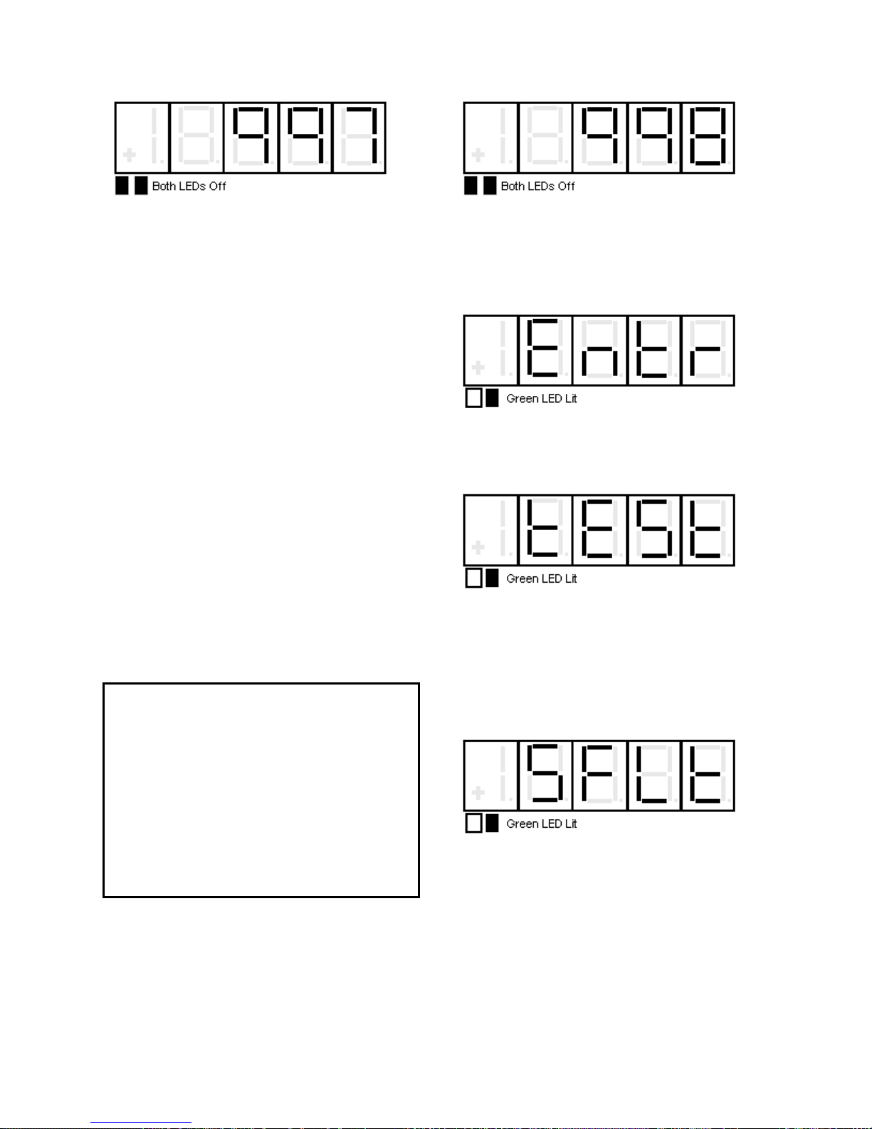
Standard Control/Display Operation
6) After completion of SELF-TUNE, enable
Function # 2. (Unless using manual entry)
Power Conversion Diagnostics
The drive has built-in diagnostic routines that
can be performed via the SCDU. The PCU
diagnostic routines are able to test for four
failure modes. The first test that the PCU
performs is a test of the three line fuses.
Assuming the three line fuses are all OK, the
PCU then performs a test for shorted SCRs/
doubler packs. If this test indicates no shorted
SCRs/doublers, the PCU then verifies that less
than 5% of the value entered for “Rated Field
Current” is attainable. The PCU then tests for
open SCRs by passing current through the
forward bridge followed by the reverse bridge,
and finally checks polarity of voltage feedback.
The result of the test is displayed on the SCDU
after the test completes. The SCDU will light
certain unique LED patterns on its display
corresponding with the failure (see displays in
the procedure that follows). The Fault Codes
F910 (Blown Fuse), F911 (Shorted SCR),
F912 (Open SCR), and F917 (Reverse
Armature Feedback Wires) will not appear on
the SCDU if the Error Disposition List is
programmed so that they are not reported to
the Fault List.
WARNING
Armature current is circulated through the
armature circuit during parts of the PCU
Diagnostics Function. The PCU will reduce
the field current to zero on motors with a shunt
field in order to minimize motor rotation.
However, a PERMANENT MAGNET motor
must have its shaft locked mechanically prior
to running the PCU Diagnostics routine. If the
PCU detects significant motor voltage during
the test, the PCU Diagnostics Function will
abort.
The process for accessing the PCU
Diagnostics Function is as follows:
1) Use the ▲ and ▼ keys to select
Function # 998 from the function level. The
two colored LEDs remain off during this step.
2) Press the DATA/FCTN key to enter the
"Data" level for Function # 998. The green
LED is now lit to indicate that this function is
currently being accessed. The SCDU prompts
the user to press the ENTER key by
displaying:
3) Press the ENTER key to actually start the
PCU diagnostics. While the PCU is performing the Function # 998 Diagnostics test,
the SCDU displays:
The PCU will not begin the diagnostic routines
if a SEVERE PCU FAULT exists. The PCU
will declare a SEVERE FAULT under several
conditions including an IST Fault, power
supply failure, line sync loss, low line, or DCU
failure. If a SEVERE FAULT exists when the
PCU starts the diagnostic tests, the SCDU
displays:
Severe faults can only be cleared by pressing
the CPU reset button on the Drive Control PCB
or by cycling power to the drive.
If the display stays on 'tESt' and the contactor
doesn't pick up, there is a fault in motor field
connections or settings.
If all tests indicate that there are no failed
power components (SCRs and fuses), the
SCDU displays:
39
Page 42
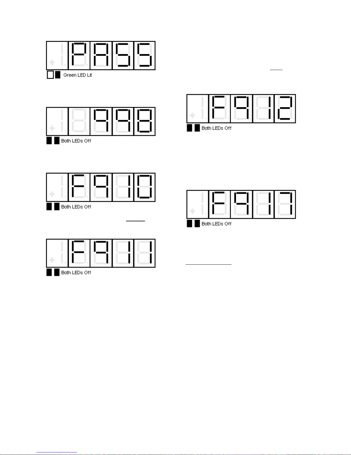
Standard Control/Display Operation
Press the DATA/FCTN key to exit the PCU
Diagnostics routine and return to the
"Function" level. The SCDU displays:
If the PCU detects one or more Open AC
Fuses, it displays the fault code for a blown
fuse (F910):
Remove power from the drive to replace the
SCR(s) that are shorted, and repeat this test
until the SCDU displays the 'PASS' message.
If the PCU detected one or more open
SCR/doubler packs, the SCDU displays the
fault code for an open SCR/doubler pack
(F912):
Remove power from the drive, consult Section
5, MAINTENANCE, to replace the SCR(s) that
are open, and repeat this test until the SCDU
displays the 'PASS' message.
If the PCU detects Reversed Armature
Feedback wires, it displays the fault code for a
Reverse Armature Fault (F917):
If the PCU detects one or more shorted
SCR/doubler packs, the SCDU displays the
fault code for a shorted doubler (F911):
Remove power from the drive, reverse the
Armature Feedback wires, and repeat this test
until the SCDU displays the 'PASS' message.
This fault also occurs if the Armature FB wires
are not connected.
40
Page 43

Drive Setup & Adjustments
Motor Field Current Control
Motor field current is held at Stand-By amps
Function # 53 when the elevator is idle. When
the Drive Enable command is given, field
current will rise as fast as possible to the level
programmed in Function # 50. The drive will
not allow a drive start to occur until motor field
current rises above the threshold level set at
Function # 32. At high speed, the motor field
current will automatically weaken to the level
set at Function # 49. If the field current
feedback fails to track the field current
reference by more than 5% for 5 seconds Fault
‘413’ will be declared. The universal motor
field control module supplied with DSD 412
can operate motor fields from 0.2 through 40.0
ADC. There are connection provisions for
using a user supplied voltage source.
Analog Velocity Follower
The elevator car controller provides an analog
velocity reference to the drive at A1TB1-63
and A1TB1-68. The signal may be bi-polar +/10 VDC to indicate speed and travel direction,
or a positive only unipolar signal with the
direction of travel selected by logic commands.
See descriptions of Function # 110 and # 115.
In most cases the signal profile will be adjusted
by the car controller for precise landing
positioning. The velocity reference passes
directly to the E-Reg closed loop velocity
controller, except for an internal rate limiter
Function # 21 to buffer any unexpected
electrical noise. Start and Stop commands are
via 24VDC logic inputs. The analog velocity
reference signal may be adjusted using
Function # 82 'Gain' or Function # 86 'Bias'.
Internal Preset Speed & Profile Generator
The elevator car controller provides 24VDC
logic input commands to select one of 7 predetermined running speeds. The DSD 412
drive generates a smooth S-Curve
acceleration profile to transition between
speed selections. Either of three separately
adjustable ramp times may be selected. The
direction of travel is determined by either a
single (up/dn) or dual (Run-Up / Run-Dn) logic
commands. There are provisions for allowing
or disallowing non-stop direction reversals.
The internal pre-set speed-operating mode is
selected by setting #110 to 2. The speed
sensitivity of pre-set speeds is altered by #82.
Set #82 to 1.00 for proper calibration.
Drive Setup & Adjustments
Serial Link Follower
The elevator car controller provides the
equivalent of an analog reference command
over a digital serial link. The drive returns
operating status conditions and messages.
Primary Start and Stop commands are 24VDC
logic for redundant safety. This operating
mode is selected by setting #110 to 3. The
speed sensitivity of the serial velocity
reference may be adjusted using Function #
82. See Preset Speed Logic Sequence on
page 50.
Armature Voltage Feedback
A DC motor with rated field current applied
produces rated armature voltage when it spins
at rated speed. This results in speed
regulation in the range of 5%. When in this
mode, operation over base speed is not
possible since the field weakening is inhibited.
When this mode is enabled it is still possible to
monitor the feedback from the encoder
although it will not used for speed regulation.
Due to the nature of this mode of operation,
the speed regulator gain is defaulted at 2
radians to prevent unstable operation (it
shouldn't require to be changed from this
point). A new parameter F#38 was added so
it won't be required to modify the normal speed
regulator gains F#39 and #40, when it
switched. See descriptions for Functions #
112 and # 113 for setting this mode.
Pre-Torque, Function #114
When enabled, the speed error integrator will
be pre-conditioned by the supplied pre-torque
signal before starting E-Reg. This will cause
motor armature current to begin at a
magnitude proportional to the pre-torque
command to prevent elevator motion or
rollback when the elevator brake is released.
The pre-torque signal will be from either an
analog or serial link digital source as selected
by software Mode switch Function # 110.
Current Ramp-Down, Function #85
When the DSD 412 drive is told to cease
operation by removal of the Run logic
command, (and after Brake Drop time if that
function is engaged) the armature current
reference ramps down to zero at a constant
rate controlled by Function # 85. When
armature current ramp-down is complete, the
contactor will be opened. In the event that the
contactor opens unexpectedly, as reported by
the feedback contact at A1TB1-7, or in the
41
Page 44

Drive Setup & Adjustments
event of a severe drive fault, there will be no
timed delay for current ramp-down.
Electronic Motor Over-Load
An electronic motor over-load function is
provided to take the place of heater type power
components. Motor armature current is
continuously monitored and the heating effect
is calculated over time. A motor overload trip
will not automatically stop the drive, but is an
important alarm signal to elevator car controller
to help prevent equipment damage.
External/Auto Fault Reset, Function #101
An external Fault Reset command signal from
the car controller may be applied to logic input
A1TB1-49. Or, an automatic Fault Reset will
occur 5 seconds after a drive fault occurs, if
enabled by Function # 101. This will enable
the car controller to quickly recover from a resettable fault. One Fault will be subtracted
from a fault count accumulation every 20
minutes. The maximum number of AutoResets that can be accumulated is 5. The
Auto-Reset function will then require manual
intervention.
Over-Speed Test, Functions #80 and #81
Two adjustment functions are provided to help
testing of the elevator governor over-speed
trip. Function # 81 defines a reference
multiplier value. Logic Function # 80 turns the
effect of that multiplier on and off. However,
be aware that the Drive Over-Speed trip fault
F97, set by Function # 12, is a fixed percent of
rated rpm and will also be tested, and indeed
should trip. To ensure that the drive OverSpeed Trip does not interfere with the
governor test, one must temporarily raise the
value set in Function # 12 to be above the trip
speed of the governor.
Brake Control Logic, Functions #186 and
#183
Two relay control outputs are provided (Brake
Lift, Brake Pick) by programmable output
selection functions #186 and #183. Three
timers are provided, Brake Pick #89, Brake
Drop #90, and Must Stop #91. Suggested
wiring is shown in . Operation is as follows:
Elevator Start with Brake Control:
1. The drive is started by activating first the
ENABLE then RUN command lines. The
contactor will pick (pull in), and when
acknowledge, the drive will start the current
and velocity regulator by priming it to provide
pre-torque armature current (if enabled).
The internal velocity reference will always
start at zero.
2. Once Start is confirmed, the Brake Lift and
Brake Pick lines will both become active.
This will apply full voltage to the brake coil
and cause the brake to lift.
3. The Brake Pick output will deactivate at
the end of Brake Pick time #89, and
release the internal velocity reference
clamp so that the drive can begin
acceleration. The Brake Lift output will
remain active. (Dropping of the external
Brake Pick relay will reduce voltage to the
elevator brake coil.)
Elevator Stop with Brake Control
1. Automatic setting of the Brake and drive
shutdown sequence may begin at any
speed.
2. The Drive RUN command is released by
customer’s logic. This will set the internal
reference speed to zero and start the Must
Stop Timer. The velocity regulator will
continue to control velocity and current,
driving the speed to zero via the decel
rate.
3. When the drive measures encoder speed
as being zero (adjustable by #63) the
Brake Lift and Brake Pick outputs will deenergize. The drive velocity regulator will
continue to hold zero speed while the
brake drops, as set by the Brake Drop
Timer #90.
4. When the Brake Drop Timer expires, motor
armature current ramp-down will occur, as
set by #85. This will gradually transfer
torque from motor to brake to help prevent
brake ‘thumping’.
5. When Current ramp-down is complete, the
drive will cease operating and open the
contactor.
6. If Brake Auto Stop #92 is ON, AND a zero
speed command is present, AND the drive
is stopped, the sequence of 2 – 5 above
will be activated.
NOTE: The drive will turn OFF with the
Drive Run and Enable commands still
active. These signals must be cycled to
recover and re-start from this auto-stop
operation.
If the Must Stop Timer #91 expires before zero
speed is achieved, the Brake Lift and Brake
Pick relay outputs will be de-energized and the
drive will shut down regardless of the actual
velocity. This is a secondary back up means
of ensuring that the elevator will stop.
42
Page 45
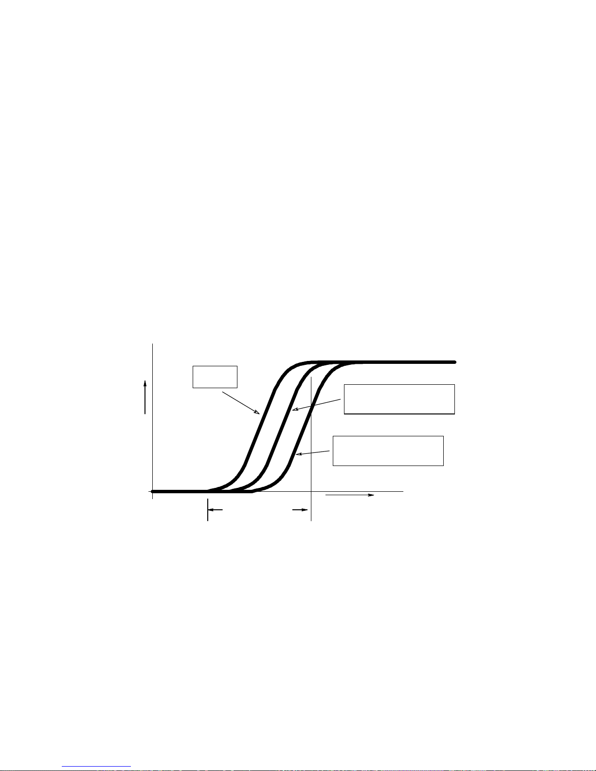
Drive Setup & Adjustments
Speed Regulator Adjustment/E-Reg
The Magnetek DSD 412 drive uses a
proprietary velocity regulator called E-Reg.
This is a double speed loop encoder feedback
regulator designed specifically for elevator / lift
applications where the objective is to smoothly
follow a repeated accel/decel speed pattern
reference with a relatively fixed load. The
following characteristics are important:
Follow the reference speed with a
consistent tracking delay, see Figure 13: EREG Tracking Profiles (1).
No overshoot at the end of acceleration
Precision speed following, including at zero
speed
Feed forward for inertia forcing
Rejection of resonant load characteristics
Ability to start with a pre-primed error to
counteract load offset rollback
Velocity
Reference
S
P
E
E
D
0
ZERO
SPEED
ACCEL TIME
E-Reg Velocity Tracking with proper PU-Inertia. No over/under shoot
Figure 13: E-REG Tracking Profiles (1)
Primary adjustments for E-Reg are:
High & Low Speed Bandwidth – #39 & 40
Sets the desired drive response from Speed
Reference changes to motor speed. Units are
Radians/sec of the closed loop crossover
frequency bandwidth. The constant time lag
characteristic of E-Reg will be 1/Response, in
seconds. Increasing the Response setting will
increase the gain to improve velocity-tracking
performance. A setting of 5.0 – 8.0 for the
Response is normal for most elevators.
Setting the Speed Bandwidth to a high value in
order to compensate for a poor Per Unit Inertia
setting is an improper adjustment. There may
be some minor interaction between the
Bandwidth and Stability adjustments.
RATED SPEED
Speed Feedback with Bandwidth
(#40) set to 10 radians,
100 mSec tracking delay
Speed Feedback with Bandwidth
(#40) set to 5 radians,
200 mSec tracking delay
TIME
43
Page 46
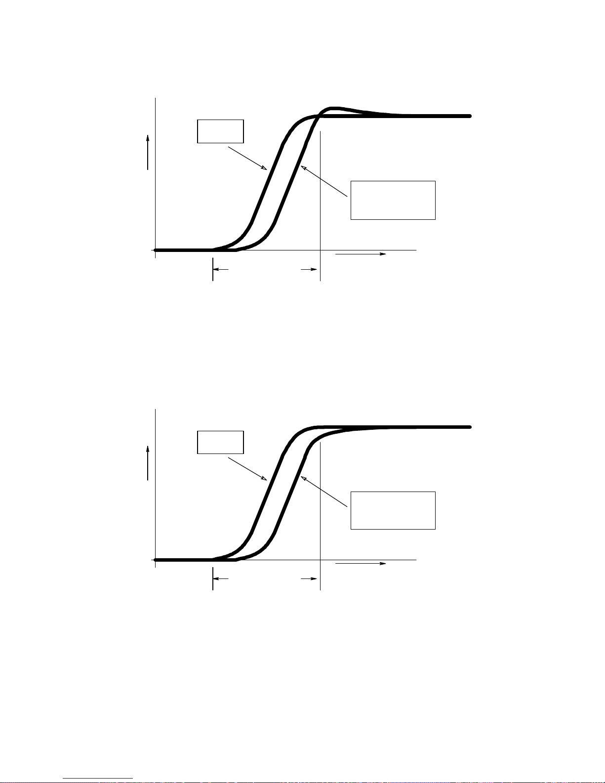
Drive Setup & Adjustments
Velocity
Reference
S
P
E
E
D
Speed Feedback with
Per-Unit Inertia (#41)
Velocity Overshoot
0
ZERO
SPEED
ACCEL TIME
TIME
E-Reg Velocity Tracking with Per-Unit Inertia Setting TOO LOW, Velocity Over-Shoot
RATED SPEED
set too low,
Figure 14: E-REG Tracking Profiles (2)
RATED SPEED
Velocity
Reference
S
P
E
E
D
0
ZERO
SPEED
ACCEL TIME
Speed Feedback with
Per-Unit Inertia (#41)
set too high,
Velocity Undershoot
TIME
E-Reg Velocity Tracking with Per-Unit Inertia Setting TOO HIGH, Velocity Under-Shoot
Figure 15: E-REG Tracking Profiles (3)
44
Page 47

Drive Setup & Adjustments
Field Regulator Set-Up
Proper control of motor field current requires
knowledge of the motor field resistance, the
electrical time constant, and the line voltage
available to control power to the motor field.
Motor field resistance is calculated from the
settings of Rated Field Volts #52 and Full Field
Current #50. The time constant and available
AC input voltage is supplied by settings #51
and #55. If a separate source of field circuit
voltage is used, #55 should be set at that
voltage. Otherwise leave #55 set at zero to
automatically utilize the main input voltage
setting of #9. If #2 is set to ON, the Self-Tune
measured value for L/R #615 will be used
instead of #51. Verify that the above settings
are correct. The scaling of measured motor
field current is also important. Verify that the
motor field wiring is connected correctly to the
proper ampere range tap at TB4, and that
SW1 is set accordingly. Check the calibration
of measured field current, drive display #612,
against that of a separate DC clamp-on
ammeter clipped around a motor field wire.
If motor field weakening is not required at top
speed leave WEAK FIELD CURRENT #49 set
to 40 amps or set it equal to RATED FIELD
CURRENT #50. Set STANDBY FIELD
CURRENT #53 as desired during drive idle.
If top speed is greater than the motor base
speed, set WEAK FIELD CURRENT #49 so
that actual motor voltage does not exceed the
RATED ARMATURE VOLTS #7 during a high
speed, full load run. The crossover point
between Full Field and Weak Field current will
be automatically calculated. Motor field
current will be adjusted by those settings and
measured encoder speed. The DSD 412 drive
does not directly regulate armature voltage.
This is determined by field current adjustment
settings and measured rotational speed.
Be sure to adjust motor field current so that
rated armature voltage is achieved at top
speed before attempting to set Per-Unit Inertia.
Note: If Field Current is set too low, the
necessary motor torque may not be available,
resulting in excessive motor armature current
or current limiting. If Field Current is set too
high, the armature voltage may exceed
voltage-limiting points, resulting in faults F407
or F408. Either condition may create an
elevator tracking error. To properly set #50
Full Field amps put full load in the elevator and
run in the up direction at 20% contract speed
while monitoring #611 armature current
feedback. The goal is to run at #3 rated motor
amps. Decrease #50 to increase armature
current. Increase #50 to decrease armature
current, but be aware that this may cause
unwanted motor heating. To set #49 weak field
amps run the elevator at balanced load, 100%
contract speed, monitor #610 Armature Volts
and adjust weak field amps until the motor is
running at #7 rated armature volts. Reduce
weak field amps #49 to reduce armature volts.
Increase Weak Field amps to increase
armature voltage. Ensure that the nominal
voltage on the secondary of the isolation
transformer is 10-20% greater than rated
armature voltage #7.
AC Input Voltage Requirement & Adjustment
The line-to-line AC RMS input voltage to the
drive should be greater than or equal to the
rated Full Load Armature Voltage.
To adjust the transformer taps, run the elevator
at full motoring load and rated motor RPM.
(Empty car down) During the constant speed
portion of the profile, measure the AC voltage
input to the drive (Secondary of Isolation
Transformer), #619, and the DC Armature
Voltage #610.
If the Armature Voltage is greater than the
Input Line Voltage, adjust transformer primary
taps to get the next higher voltage level on the
transformer secondary.
Per-Unit Inertia, Function #41
Be sure to have completed adjustment of the
motor field current regulator BEFORE making
final adjustments of system inertia. Start with
default values for Response Bandwidth #39
&40, Per Unit Inertia #41 and Stability #42.
Use a speed profile with a minimal amount of
S-Curve smoothing. Select two elevator
landings far enough apart so that the elevator
can attain maximum speed between stops.
[But not the end landings during initial tuning.]
It is a good idea to begin at a restricted low
speed like inspection speed for initial
verification. Run the elevator up and down
repeatedly between the same two landings
while monitoring car speed via function #600
on the DSD 412 local display. The objective is
to have the car speed accelerate right up to
the desired speed, so look for speed overshoot
or undershoot as the car reaches set speed.
If there is speed overshoot – INCREASE the
setting for Per Unit Inertia #41 in proportion to
the amount of overshoot.
If the speed ramps up as expected but slowly
creeps up to the final desired speed
45
Page 48

Drive Setup & Adjustments
(undershoot) – DECREASE the setting for Per
Unit Inertia.
Repeat the above at higher set speeds until
the car will accelerate up to rated top speed, or
decelerate back down to zero speed, without
over/under shoot. Ideally, the Per Unit Inertia
should be set with a balanced carload as this
represents a typical payload. If initial tests are
made with an empty car, increase the setting
found with the above method by 10% to
estimate the additional effect of passenger
payload. Save this setting using the DSD 412
function #994.
Stiffness, Function #42
Sets the gain of internal PI error amplification
and inner loop regulator gain. Affects the
responsiveness of the drive to ignore or react
to load disturbances. Range 0.5 to 9. No
calibrated units. Low numeric values will yield
smooth performance while following reference
changes. High numeric values will yield better
response to speed errors and load
disturbances, but can cause amplification of
elevator rope resonance.
Gain Switch Speed and High Speed
Bandwidth,
Function #105 and #39
If higher settings of Speed Bandwidth and
Stability are necessary to achieve repeatable
good floor landing and take-off characteristics,
but rope oscillations or other mechanical
vibrations occur at higher speeds a good
countermeasure is to lower the bandwidth
setting (gain) at higher speeds. Set the Gain
Switch Speed #105 to a speed below where
the vibrations occur. Set High Speed
Bandwidth #39 to a value less than that of #40
to help suppress system oscillations.
Gain Reduce, Function #108
The Gain Reduce multiplier function has been
replaced by two separate settings, #39 & #40.
Tach Rate Gain, Function #107
This function controls derivative encoder
feedback. Increase this setting to suppress
rope stretch bouncing or similar other
disturbances. Very helpful in high rise
buildings for smooth landing performance.
However – This feature can sometimes cause
amplification of minor vibrations, causing them
to become worse. Keep this adjustment set to
zero unless demonstrated to provide a useful
purpose.
Notch Filter, Function #190 & #191
Some hoist ways may have rope resonance’s
that cause occasional vibrations, roughness of
ride or continuous oscillations at certain low
frequencies (9-14 Hz). There may be critical
hoistway locations or payload weight
combinations that tend to be more sensitive
than others. The effects are often felt rather
than heard. The frequency sensitive notch
filter, placed in the software path of the torque /
armature current reference signal, can be
effective to suppress the response of the DSD
412 drive to amplify those frequencies.
Adjustments for this filter are via #191, the
period, or center frequency of the filter, and
#190, the depth of the notch, or its ability to
attenuate. See
Table 11: Notch Period Steps.
Use the filter as follows:
Determine the approximate frequency of
the oscillations or rope ‘ringing’.
Use Function #191 to set a center
frequency value slightly higher than that of
the observed disturbance. The default
value of 7 (12 Hz) will be sufficient in many
cases.
Increase the value of #190 to suppress
the tendency to respond or amplify rope
resonance.
CAUTION
Be aware that the ability of the drive to follow
the speed commanded by the car controller is
altered by these adjustments. If the frequency
of the filter is set too low, or the notch depth is
set too deep, there may be interference
problems associated with operating the closed
loop velocity regulator or position control loops
within the Car Controller. Typical symptoms
would include position overshoot of floor
landings and potentially repetitive speed
oscillations or speed ‘hunting’. If these
symptoms occur, back off on the Notch Depth
setting #190 and/or reduce the setting of
#191 (Notch Period), increasing the notch
center frequency to avoid interference.
46
Page 49
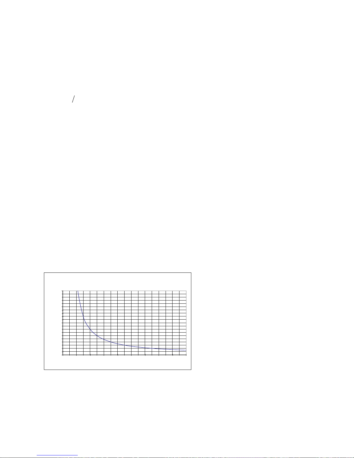
Motor Overload
Motor armature current is sensed and
mathematically integrated over time to detect
potential over heating caused by a dragging
brake shoe or other repeated abuse beyond
ratings of the equipment. The calculation
formula used for the electronic motor overload
is:
)(2 KoiTt
Where:
t = Calculated time to trip in seconds
i = Measured Per Unit motor current. Drive
Param #3 defines motor Per Unit current in
amperes.
T = Time to trip setting #83 at motor current of
(Ko+0.5) per unit current.
Ko = Maximum Per Unit current that will not
cause an Overload Trip #84.
The USA National Electric Code (NEC)
requires that the overload be adjusted to
detect overheating of the motor and motor
wiring by using rated motor current as the
comparison base. This is not the same as
rated current capability of the drive. The NEC
requirement is that the overload must trip at
1.15 PU current (no time specified), and after
60 seconds at 1.5 PU current, and after 10
seconds at 2 PU current. It is recommended
that the default values of Ko=1.1 and T=50 be
used. This will provide no tripping with
average motor current of 1.1 PU or less, and a
tripping time of 62 sec at 1.5 PU. See the
timing graph of Figure 16: Motor Overload
Overload Trip Time
Ko=1.1, To=50
200.0
150.0
100.0
Seconds
50.0
0.0
1 1.2 1.4 1.6 1.8 2 2.2 2.4 2.6 2.8
Per Unit Current
MOTOR OVERLOAD, Ko=1.1, T=50
Figure 16: Motor Overload
Drive Setup & Adjustments
Start – Stop Timing
A typical elevator run sequence is shown in
Figure 17. A descriptive explanation is given
below.
Start Sequence – Mode 2, internal pre-set
speeds
1. Close Drive & Field Enable – Sets field
current reference to Full Field, enables
drive to operate. This contact must be
held closed during entire elevator run,
including armature current ramp down.
Opening of this contact will disable the
drive and cause the loop contactor to be
dropped immediately.
2. Close Safety-Chain circuit. – Must be
closed for drive to start. Must remain
closed during entire elevator run.
Otherwise, an F405 fault will result.
3. Select desired direction and speed – Might
be done before or after drive is told to Run.
4. Close Hardware Run (or Run-Up or RunDown contact) – Causes LPR to pick when
field current is greater than setting #32.
LPR picks contactor, which closes Loop
Confirm – Drive will begin running by preloading the speed error integrator with the
available pre-torque signal, if enabled at
Function #114. Logic Output Selection ‘C’,
Run Engaged, will become energized to
indicate that the drive has control of motor
speed. Speed will begin to accelerate
toward desired speed, if not set at zero. If
contactor fails to pick, F402. If motor
armature circuit is not closed before
Loop Confirm closes, an F98 or F901
may occur.
5. Release brake - Timing of actual brake
release must be coordinated with
starting the drive and/or changing the
target speed. The drive must be
running and be either pre-torqued, or
starting to accelerate, or have ARB
engaged to prevent rollback.
6. A new target speed and or direction
may be selected before or after the
drive is started. When speed rises
above the setting of #64, the Low
Speed logic indicator will turn off.
(Output function ‘F’)
47
Page 50

Drive Setup & Adjustments
Stop Sequence
1. Select leveling or zero speed reference –
Will cause start of deceleration to new
target speed.
2. When speed becomes less than the
setting of #64, the Low Speed logic
indicator will become active to indicate a
door pre-opening speed. (Output function
‘F’)
3. Select zero speed – Will cause drive to
decelerate to zero speed & hold car
position. When speed drops below the
setting of #63, the Zero Speed logic
indicator (Output function ‘J or K’) will
become active.
4. Set elevator brake – Wait the appropriate
amount of time for the brake to drop, or
use a brake limit switch to confirm when
the brake is physically set.... Then
5. Open Hardware Run contact (or Run-Up or
Run-Down contact) – Will cause drive to
stop controlling speed, turn the Run
Engaged logic indicator (Output function
‘C’) off, and ramp armature current down
to zero in time set by function #85. Drive
will open LPR, contactor, & Loop confirm
when Ramp-down is complete. If
contactor confirm fails to open, F402 fault
will result.
6. Open Safety Chain (if desired) – Must
remain closed for current ramp-down to
happen. If current ramp-down is not
desired, set #85 to minimum. Expect
some contactor barking. If Safety Chain
opens unexpectedly while drive is running,
F405 fault will result. Safety chain may
remain closed.
7. Open Drive & Field Enable (if desired) –
Will cause field current to go to standby/idle value. May remain active if drive
will be restarted shortly. However, if drive
is not restarted within 5 minutes with Drive
& Field Enable active, F403 fault will result.
48
Page 51
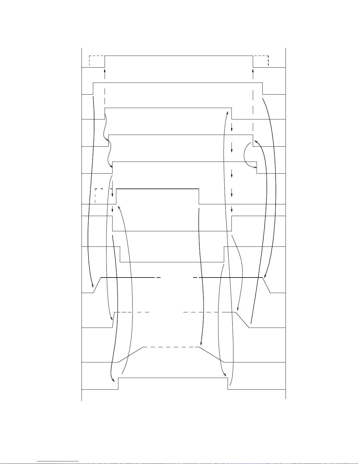
SAFETY
CHAIN
DRIVE & FIELD
ENABLE
HARDWARE
RUN
LPR /
CONTACTOR
CONTACTOR
ACK
SPEED
DIRECTION
& RAMP
CMDS
RUN
ENGAGED
ZERO
SPEED
MOTOR
FIELD
CURRENT
MOTOR
ARMATURE
CURRENT
ELEVATOR
VELOCITY
ELEVATOR
BRAKE
PRE-
TORQUE
MUST REMAIN VALID DURING ENTIRE RUN
AS REQ'D DURING RUN
FIELD
WEAKENING
IF REQ'D
AS REQ'D
DURING RUN
ACCEL DECEL
Drive Setup & Adjustments
1
0
1
0
1
0
1
0
1
0
RUN
SPEED
ZERO
SPEED
1
0
1
0
FULL
STAND-BY
OTHER
RAMP
DOWN
ZERO
OTHER
ZERO
RELEASED
SET
Figure 17: Elevator Start - Stop Timing
49
Page 52

Drive Setup & Adjustments
Stopping Distance
The internal S-Curve velocity generator of the
Magnetek DSD 412 drive is digital in nature
and is therefore very repeatable. The
Accel/Decel time is fixed per the selected rate
adjustment setting. The time setting
represents the total acceleration time from
zero to rated speed (or vice-versa), and is
independent of any S-Curve selection. The
starting and stopping distance from and to any
other digitally pre-set speed can be precalculated and will also be repeatable.
The distance traveled during deceleration to
zero or to a lower leveling speed will be:
S = Tsec x DeltaFPM/RatedFPM x
(LevelingFPM/5 + DeltaFPM/10)
(inches)
Where DeltaFPM is the change in steady state
running speed in feet per minute
However there is fixed delay and an
uncertainty of actual time to recognize and
start obeying a logic command to start the
deceleration cycle. The fixed delay is 0.01
seconds and the uncertainty is 0.018 seconds
maximum. During this time the elevator will
still be moving at running speed, creating an
uncertainty in the actual stopping distance.
This delay plus uncertainty distance will be:
Serror ≤ RunningFPM x 0.028 x
12/60 = RunningFPM x 0.0056
(inches)
So the total maximum stopping distance or
deceleration distance to leveling speed will be:
Stotal ≤ Tsec x DeltaFPM/RatedFPM
x (LevelingFPM/5 + DeltaFPM/10) +
RunningFPM x 0.0056 (inches)
For multi-floor runs, the slow-down vane switch
must be at least that distance from the landing
or the floor may be missed.
For single floor runs, the acceleration distance
may be calculated similar to above, without the
uncertainty error. The slow-down vane switch
for the next landing must be at least that far
away from the beginning of the run. The single
floor target running speed and/or accel/decel
times must be adjusted to meet the above
criteria conditions or the landing may be
missed.
Note that if minimum flight time is desired a
different deceleration rate may be selected to
optimize the result. A longer decel time can
result in a faster flight time since less time is
spent at leveling speed. A second set of
accel/decel parameters may be activated by
use of the optional Ramp Rate Select contacts.
An optimizing procedure would be:
1. Set the Accel Time and percent jerk for
ride quality.
2. For short runs, (i.e. where the distance
from the starting floor to the vane switch is
less than the distance from the vane
switch to the stopping floor) set the target
speed so that the accel distance is less
than the distance from the start to the vane
switch.
3. Set the Decel Time so that the stopping
distance is just a little less than the
distance from the vane switch to the
stopping floor.
4. For multi floor runs set the speed to
contract speed and set the decel time so
that the decel distance is just slightly less
than the distance from the vane switch to
the target floor. Other options certainly
exist.
Preset Speed Logic Sequence
Binary - The internal pre-set-speed selector in
binary mode (Fctn #150 ON) uses 3 input lines
to select 1 of 8 pre-set speeds (including zero),
see Table 6. Binary logic reduces the number
of control lines but the logic inputs to select
those independent speeds may not be properly
de-bounced at the sending or receiving end.
This may allow an unintended speed to be
momentarily selected. To prevent this from
happening, the user should consider using 4
pre-set speeds, including zero, selected in a
gray scale progressive manner (only one
switch changes at a time).
Progressive - An alternate method of one-at-atime control that has more pre-set speeds and
takes advantage different Ramp Rates (R-R)
during operation, set #150=Off for Progressive
input control, see
Table 7. Connect A1TB1-10 to A1TB1-54, and
A1TB1-51 to A1TB1-12 to automatically
activate R-R 2 with a 1 Floor Run and R-R 3
with Multi-Floor runs. R-R 1 will be activated
for leveling and inspection, speed #1. If Decel
Rate Latch #116 is ON, these rates will be held
active during deceleration.
Note: R-R 3 overrides R-R 2 which overrides
R-R 1.
50
Page 53

Drive Setup & Adjustments
Example:
(With #150=On)
S2 S1 S0 Pre-set # Use
0 0 0 none Zero Speed select
0 0 1 1 Leveling Speed
0 1 1 3 1 Floor Run Speed
1 1 1 7 Multi-floor Run Speed
0 1 0 2 Inspection Speed (could also be speed 4, 5, or 6)
NOTE: Always set all other unused pre-set speeds to zero.
Table 6: Binary Input Control
Example:
(With #150 = Off, & #112 = On)
S4 S3 S2 S1 S0 Pre-set # Use
0 0 0 0 0 none Zero Speed select
0 0 0 0 1 1 Inspection speed w/ R-R 1 rates
0 0 0 1 0 2 Leveling Speed, w/ R-R 1
0 0 1 1 0 3 1 Floor Run Speed, w/ R-R 2
0 1 1 1 0 4 Multi-floor Run Speed, w/ R-R 3
1 1 1 1 0 5 Express zone speed (optional)
Table 7: Progressive Input Control
Drive & Field Enable
The Drive & Field Enable contact input enables
the drive to run and also acts as a command to
fully energize the motor field. Closing Drive &
Field Enable in advance of the Hardware Run,
or Run-Up / Run-Down, command will allow
time for the motor field to become fully
energized for a minimum of starting delays.
When the Drive & Field Enable circuit is open,
the motor field circuit will be energized at the
stand-by current level. If Field Enable remains
ON for more than 5 minutes without running
the drive, an F403 will occur and the Full Field
condition will be turned OFF.
RUN w/ DIRECTION & RUN-UP / RUNDOWN
One of two methods may be selected to Run
the drive and determine the direction. Use
function #115 to select.
1.) Hardware Run & Reverse (#115 = Off)
The Hardware Run input starts the drive. The
Reverse contact controls the direction. The
Drive & Field Enable signal must also be
energized and remain so for this to occur. The
desired direction command should be stable
before a non-zero speed reference is selected.
CAUTION – The direction control from this
input is not interlocked with any other logic
condition. This facilitates direction control
while re-leveling or performing a quick reverse
while heading for a ‘home landing’, but it also
means that an intermittent contact or broken
wire can make the car go in the wrong
direction!
2.) Run-Up & Run-Down (#115 = On)
Two separate logic inputs are provided to start
the drive in either the up or down direction.
The Drive & Field Enable signal must also be
energized and remain so for this to occur. If
both Up and Down directions are active
simultaneously, the drive will not start. This
prevents a single relay contact or wiring failure
from starting the drive in the wrong direction.
Once running, the direction may be reversed
by closing the contact for the new direction and
releasing that for the old. This is allowed at
any speed. If the command contact closures
overlap, speed control will remain active and
the contactor will not drop.
Using External Velocity Commands
Operation with an external analog velocity
command is similar to the sequences above.
This mode is programmed via the logic select
function #110. Setting #110 to a 1 enables the
bi-directional analog follower mode. The
actual car direction will always follow the
polarity of analog reference. Both the Drive &
Field Enable and the Hardware Run signals
must be active to cause the drive to run.
When function #110 is set to 4, the uni-polar
analog follower mode is active. The drive will
control the speed of the elevator based on the
positive value of the supplied analog
reference. The direction of travel will be
51
Page 54
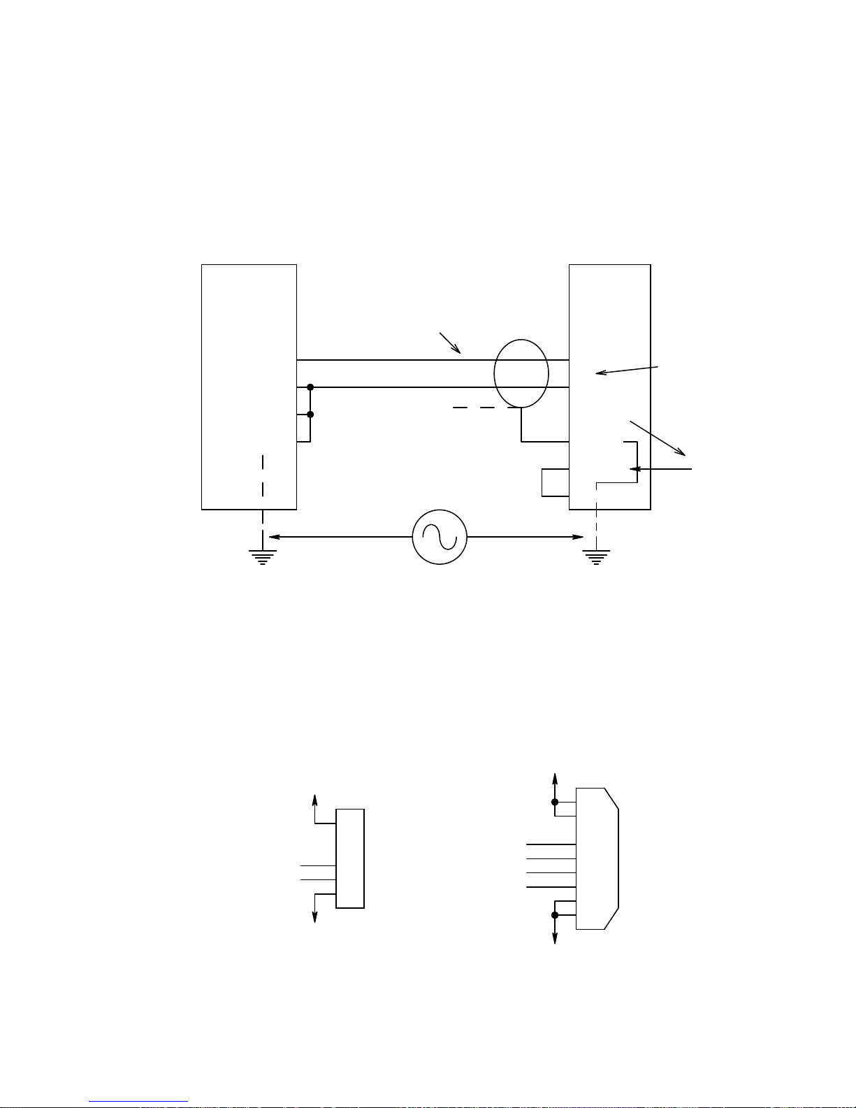
Drive Setup & Adjustments
determined by the status of either the direction
select (function #115 =OFF) or Run-Up/RunDown (function #115=ON) logic input
command lines. Both the Drive & Field Enable
and the Hardware Run signals must be active
to cause the drive to run.
Avoiding Analog Signal Ground Noise
Analog reference wiring is sensitive to
electrical noise interference. The reference
signal channels are differential and should be
wired with twisted pair, shielded cable, as
shown in Figure 7: Typical Analog Signal
Wiring. Be sure that the cable shield is
connected only at the drive end.
CAR
CONTROLLER
PLC
RefOut +
RefOut -
Common
GND
Common mode voltage noise is rejected at differential reciever.
Serial Link Connections
MAGNETEK
Twisted & Shielded
TB1
(68) +
(63) -
N.C.
at PLC end
Vnoise
(66,70) com.
(69) shld
(44 OR 43)
(TB11) GND
Proper connections.
Noise current does not flow through signal wires or shield.
Figure 18: Analog Signal Ground Noise
DSD-412
DC DRIVE
Differential
Input
Circuit
Common
RS-232
TXD
RXD
CIRCUIT
COMMON
+5V
J2
RJ-12
1
2
3
4
5
6
Figure 19: Serial Link Connections
52
RS-422
TX+
TXRX-
RX+
CIRCUIT
COMMON
+5V
J1
DB-9
1
6
2
7
3
8
4
9
5
Page 55
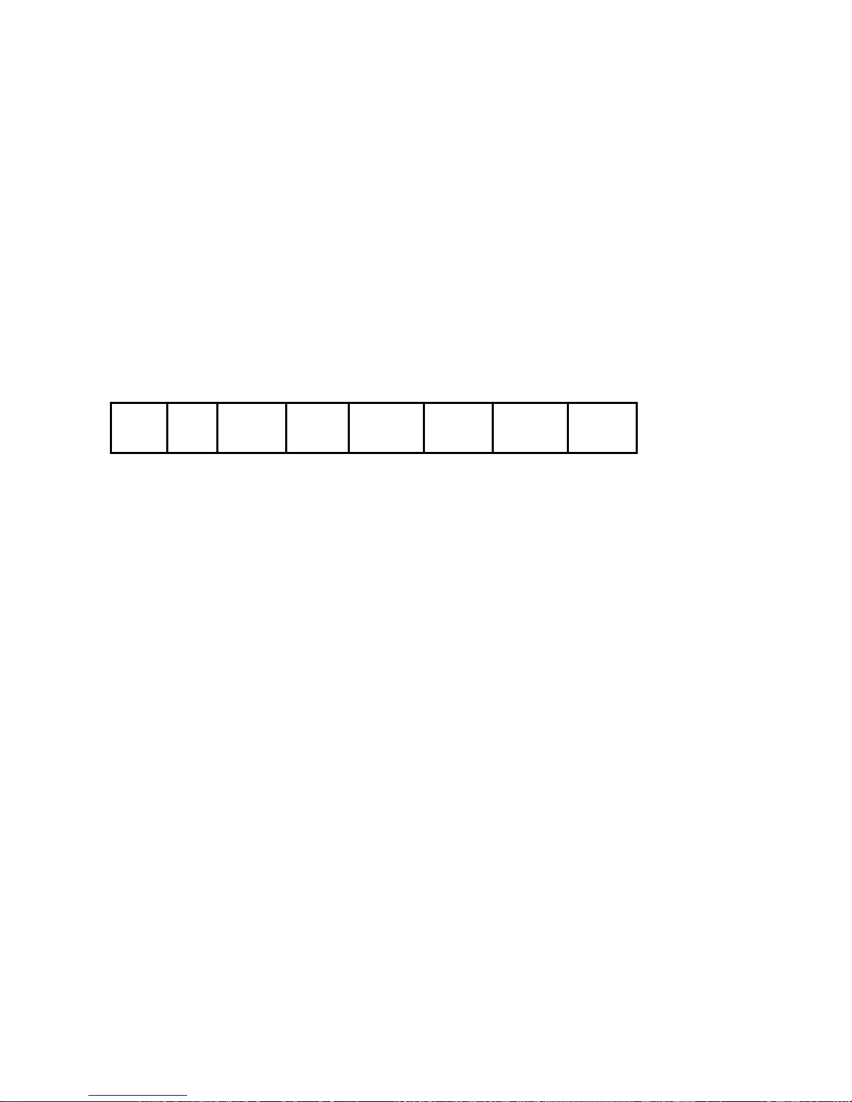
Drive Setup & Adjustments
Serial Communication Specification
See Function #110 to enable this feature. The
serial communication link between a host and
the DSD 412 consists of two messages. There
will be a Demand Velocity/PreTorque
Command sent from the host to the DSD 412
every 15 MS. There will be a Demand Velocity
Response message sent from the DSD 412 to
the host every 45 MS.
After power up the drive will wait 10 seconds
for the first Drive Velocity Command (DC)
message to be received from the car
COMM FLT (F117) will be declared. Once
communications has been established, a valid
DC message must be received at least in 150
MS intervals. If this time window expires, a
150 MS COMM FLT (F118) will be declared.
Frame format: 10 bits (N81) @ 19.2K baud.
RS232 may be used with the 46S02975-03xx
Drive Control PCB at connector J2. RS422
requires the 46S02975-04xx PCB with a DB9
J1 connector. Pin-out is per Figure 19: Serial
Link Connections.
controller. If this time expires, a 20 SEC
Demand Velocity Command message from the host is as follows:
Byte 1 Byte 2 Byte 3 Byte 4 Byte 5 Byte 6 Byte 7 Byte 8
Sync
Byte
FAh
Bytes 1&2: These bytes will always be set to FAh and 05h respectively. They are used for the
purpose of synchronizing the DSD 412 to the start of an incoming message from the host.
Byte 3: {N259_C001} This byte contains the logic commands sent from the host to the DSD 412. The
bit definitions are listed below:
B0: =1 to act as a synchronization bit for incoming messages from the host.
B1: =1 to act as a synchronization bit for incoming messages from the host.
B2: 0=Stop requested 1=Run requested
B3: 0=No request to clear faults 1=Clear fault requested
B4: 0=Demand Velocity is not DOWN 1=Demand Velocity is DOWN
B5: 0=Demand Velocity is not UP 1=Demand Velocity is UP
B6: 0=Idle field command 1=Full field command
B7: A rising edge of this signal acts as a latch to capture the Numeric Command and interpret it as
a new Pre-Torque value. This signal should be set to a zero by the host before it sends a new Pretorque value or when the host receives confirmation that the drive is in the run mode.
Byte 4: {N259_C002} This byte contains additional logic commands from the host to the DSD 412.
[Drive function #104 must be set to a 1 for this control to be active.]
B0: 0= No gain reduction 1= Velocity loop gain reduction is ON
B1-B7 are spares
Bytes 5&6: {N259_C000} These two bytes represent a signed 16 bit numeric value. The
definition of this value is determined by the status of Byte 3, Bit 7. If bit 7 is a 1, the value will be
interpreted as a pre-torque signal. If byte 3, bit 7 is a 0, the value will be interpreted as a velocity
reference. The limits for this value are: 7FFFh = +1 per-unit, 0000h = zero, 8000h = -1.0 per-unit.
Byte 7: The data in this byte is passed to the PCDU routines and is interpreted as a new PCDU
keystroke. If no 'key' is being pressed (a great majority of the time) the value of this byte will be 00h.
It is the responsibility of the host to insure that this byte contains the new non-zero keystroke data for
only one 15 MS transmission period. If this is not done, the DSD 412 will act as if a given key is being
'held down' instead of being pressed and released. The host must pace the placement of non-zero
data in this byte no more frequently than one character every 250 MS. This is done to give the PCDU
routines enough time to transmit the proper response display (possibly up to 32 ASCII characters)
before the next keystroke is read.
Sync
Byte
05h
Logic
command
Byte 1
Logic
comman
d Byte 2
Numeric
command
(high byte)
Numeric
command
(low byte)
PCDU
keystroke
Checksum
53
Page 56
Drive Setup & Adjustments
Byte 8: This byte contains the calculated checksum of the data within this packet. It is the modulo-
256 sum of bytes 1 through byte 7 inclusive.
Demand Velocity Response message from the DSD 412 is as follows:
Byte 1 Byte 2 Byte 3 Byte 4 Byte 5 Byte 6 Byte 7 Byte 8 Byte 9 Byte 10 Byte 11
Sync
Byte
FAh
Sync
Byte
05h
Control
Status
1
Control
Status 2
Control
Status 3
Bytes 1&2: These bytes will always be set to FAh and 05h respectively. They are used for
synchronizing the host to the start of an incoming Demand Velocity Response message from the DSD
412.
Byte 3: {N259_C010} This byte contains 8 logic status signals as defined below:
B0: =1 to act as a synchronization bit for the host
B1: =1 to act as a synchronization bit for the host
B2: 0=Tach direction is not UP 1=Tach direction is UP
B3: 0=Tach direction is not DOWN 1=Tach direction is DOWN
B4: 0=No tach overspeed fault 1=Tach overspeed fault F97
B5: 0=No tach loss fault 1=Tach loss fault F98
B6: 0=No reverse tach fault 1=Reverse tach fault F99
B7: 0=No Serial Communications Fault 1=Serial Communications Fault
Byte 4: {N259_C011} This byte contains 8 logic signals to indicate drive faults.
B0: 0=No Motor over-load 1=Motor over-load fault F400
B1: 0=No excessive field current 1=Excessive field current F401
B2: 0=No contactor failure 1=Contactor failure F402
B3: 0=Drive is not at CEMF limit 1=Drive is at CEMF limit F407 or F408
B4: 0=E-STOP circuit is closed 1=E-STOP circuit is open
B5: 0=No E-STOP fault 1=E-STOP fault F405
B6: 1=No drive fault exists, READY 0=A drive fault exists, NOT READY
B7: 1=Drive NOT READY 0=Drive is READY
Byte 5: {N259_C012} This byte contains 8 logic signals to indicate additional faults:
B0: 0=No Loop fault exists 1=Loop fault exists F900
B1: 0=No PCU IST fault 1=PCU IST fault F901
B2: 0=No line synchronization failure 1=Line synchronization failure F903
B3: 0=No low line fault 1=Low line fault F904
B4: 0=No field loss fault 1=Field loss fault F905
B5: 0=No Line Droop 1=Line Droop below 90% of nominal F406
B6: 0=Speed Regulator not Released 1=Speed Regulator is Released
B7: Spare
Bytes 6&7: These two bytes contain an echo of the most recent Numeric Command target value
from the host. The format of the value is identical to that previously defined in the Demand Velocity
message.
Bytes 8-10: These 3 bytes contain ASCII display data normally intended for a serial terminal device
connected to the host. The host should simply pass all non-zero data (displayable ASCII characters)
that it receives in these two slots to the device that is emulating the PCDU. The host may ignore bytes
in these fields if they are set to 00h meaning that the DSD 412 has no data to display at this time. A
full PCDU display is 2 rows of 16 characters. Therefore, an update of an entire screen would require
several packets.
Byte 11: This byte contains the calculated checksum of the data within this packet. It is the
modulo-256 sum of bytes 1 through byte 10 inclusive.
Numeric
Data high
byte
Numeric
Data low
byte
PCDU
display
1
PCDU
display
2
PCDU
display
3
Checksum
54
Page 57

Using Anti-Rollback (ARB)
Elevator rollback occurs when an elevator
motor drive is started and the brake is released
but the hoist motor has not yet developed
enough torque to prevent gravity from moving
the car. The car may move up or down
depending on the overall balance of equipment
and payload. Velocity regulators normally
used for speed regulation will eventually detect
unwanted movement and react to halt the car.
But there will be a position error accumulated
during that process that can represent many
inches of unwanted car movement relative to
the landing. This effect is most noticeable with
low friction gear-less elevators. It may be
totally masked by the friction of an elevator
driven through worm gears. Rollback by itself
does not pose any hazards, but it does give an
uneasy, out of control feeling to passengers.
In many installations brake release timing is
adjusted so that the brake is released just as
the car begins to accelerate toward the next
landing to mask the rollback effect. This often
results in jerky starts as the brake linings
release. The correct countermeasure is to
weigh the car just as the doors close to
determine the degree of gravity unbalance,
then pre-torque the motor so that when the
brake is released all forces are balanced. This
method is very effective, but does require
expensive calibrated load weighing equipment.
The purpose of the Magnetek Anti-rollback
feature is to help prevent rollback on elevators
that do not use load weighing or do not use the
motor pre-torque capability provided by the
Magnetek drive. It uses a double integrator
(type 2) regulator when operating at zero
speed to hold the elevator car at an average
speed of zero and to regulate a constant
position as the brake is released. When the
velocity reference leaves zero speed to
accelerate the car toward the next landing, the
active velocity regulator is switched to be EReg to precisely track (follow) the velocity
reference profile. Be aware that this antirollback feature works from
encoder/tachometer signals. So there must
and will be some movement in order for the
feature to function, but the position error
generated by elevator movement will recover.
The bandwidth gain of the system will
determine how much movement will occur.
Several new operating options and
adjustments are provided. Refer to the
individual descriptions for Drive Functions
#130 - #132 and #63.
Drive Setup & Adjustments
Set-Up And Tuning Of Anti-Rollback (ARB)
1. The ARB function uses adjustment
settings #41 (Per Unit Inertia), and #42
(speed regulator Stability). These settings
and others are critical for good
performance of the E-Reg velocity
regulator. The first step for good ARB
performance is to disable ARB by setting
#130 to 0 (zero) and to tune all other EReg adjustments for a smooth ride and
good floor-to-floor elevator performance.
Be sure that the car weight and
counterweights have been adjusted to be
at the final values. Follow the suggested
procedures for tuning E-Reg as listed in
this Tech Manual. Ignore elevator rollback
while adjusting primary elevator
performance features. If rope resonance
exists, also adjust the notch filter for
minimum interference. Then tune up ARB
last as necessary to prevent elevator
rollback with an unbalanced payload.
2. After all other adjustments are satisfactory,
set #130 to a 1 to enable ARB when
starting an elevator run. Set up the
following initial ARB adjustment values.
Be sure to read ADJUSTMENT HINTS and
CAUTIONS listed below.
a) Set #131, ARB Bandwidth, to 1.5 to 2
times the setting in #40.
b) Set the initial value of #132, ARB
damping, to 0.5.
c) If the drive will be using an internally
generated velocity reference or serial
link commands (#110 set to 2 or 3) set
#133, ARB Speed Threshold to 10.0%.
If the drive will be using an external
analog velocity reference (#110 set to
1), set #133 to a minimum of 1.0%.
3. With the car empty at a convenient
landing, prepare to start the elevator drive,
call for zero velocity from the car controller
via the normal way, release the elevator
brake, and observe any car motion. When
the car comes to a stop, the observation is
complete, set the brake and stop the drive,
again through normal control channels.
Do so and observe that...
a) The contactor picks, and the drive
starts.
b) There may be some initial upward
motion, but the car should return to its
original position within a second or so.
c) When motion is halted, there will be
motor armature current producing
torque holding the car. This can be
55
Page 58

Drive Setup & Adjustments
observed at #611 on the local display
or a separate DC clamp-on ammeter,
if available.
d) Set the brake and turn the drive OFF
via normal commands. (In that order,
to prevent the car from drifting away!)
4. Repeat #3 several times and.....
a) Increase the setting of #131 (ARB
Bandwidth) to reduce the amount of
initial movement as desired. But there
may be more jerkiness. Reducing the
setting of #131 will allow more
movement, but with less jerk. Adjust
#131 for a good compromise.
b) Reduce the setting of #132 (ARB
Damping) to speed up the position
recovery, or increase the setting for a
softer recovery, as desired.
c) If oscillations occur, release the brake
and shut down the drive or reduce the
setting of #131 to stop them. This
may be a practical limit for position
tightness in this particular hoistway.
See the hints below for using the notch
filter.
5. Change the reference velocity to run the
car at normal speeds. Make several
empty single or multiple floor runs up and
down to observe the complete starting
action. The adjustments made so far
should not alter landing position accuracy.
Ride the car to observe the quality of
adjustment.
6. If weights are available, load the car to
payload capacity. Repeat the
observations and adjustments of #4 with a
full load. In this case the initial movement
should be downward. Then repeat floor
runs as in #5 with a full load. Ride the car
to verify smoothness.
Adjustment procedure is complete.
ARB Adjustment Hints And Cautions
1. Caution, the ARB function can increase
regulator bandwidth far beyond that
required for controlling the speed of the
elevator. It does so at only near zero
speed, but when the ARB gain bandwidth
is boosted it is possible that one or more
mechanical resonant frequencies may
become excited to produce unacceptable
vibration. If an annoying vibration does
occur, try to determine the resonant
frequency. Then use the notch filter to
tune it out if possible. Be aware that the
notch filter does cause additional phase
shift lag. This can and will interfere with
the operation of E-Reg and ARB. Tune
the notch filter to the resonant frequency
and adjust notch depth to the smallest
value that suppresses the vibration. Then
turn ARB off and verify or re-tune E-Reg to
yield acceptable performance. Then retune ARB settings to control rollback.
Some hoist ways may not be compatible
with high gain ARB settings.
2. The adjustment settings for Speed
Bandwidth, Per-Unit Inertia, and Stability
#40, 41, & 42 are used by both the velocity
regulator (E-Reg) and the velocity control
portion of ARB, therefore adjustment of
#40, #41, & #42 will alter the performance
of anti-rollback controls. A high setting for
Stiffness #42 will help the velocity control
respond to changes in load but will cause
longer settling times for both velocity and
ARB position regulation. Be sure to tune
the velocity controls of the elevator
BEFORE adjusting controls for ARB
Bandwidth and Damping, #131 & #132.
Changing any ARB settings, #130 - #133,
will not interfere with other velocity control
tuning.
3. Elevator rollback is a function of gravity
load unbalance of the car. This is what
causes the car to move when the brake is
released, even though the reference
velocity may still be at zero. However,
there is a finite time required for ARB to
measure unwanted car motion via the
encoder, produce a counteracting motor
torque, and then return the car to the
original position. The reaction time is
controlled by #131, ARB Bandwidth. The
smoothness and time to settle is controlled
by #132, ARB Damping. The need for
ARB starts only when the elevator brake is
actually released, not when it is told to
release. (A subtle difference in
electromechanical timing.) But the allotted
time for ARB to function will cease as soon
as the velocity reference (internal or
external) moves away from zero speed
and crosses the threshold identified by
#133.
a) Ideally, there would be adequate dwell
time after release of the brake for ARB
settling to occur. But elevator floor-tofloor time specifications do not
necessarily allow for any time delay. If
the resulting ARB time is cut short by
release of the velocity reference
56
Page 59

before position settling is complete,
the car will begin to accelerate toward
the next landing from wherever it may
be in the ARB cycle. The position
regulator to speed regulator changeover will be smooth, but the
repeatability of velocity profile tracking
during acceleration may be altered by
the amount of load unbalance and the
value of the threshold set in #133.
Keep this setting as low as possible for
best results.
b) If #133 is set too low ARB may be
terminated too early, particularly when
using an external analog reference.
This will result in elevator rollback that
could have been prevented.
c) If acceleration of the velocity profile is
started and crosses the threshold set
by #133 before the elevator brake
actually releases, ARB will not function
and may result in elevator roll-back as
acceleration begins. This, and the jerk
or vibration sometimes felt by
passengers as the motor pulls through
the brake to start the car, is a result of
poor velocity reference release Vs
brake release timing. With ARB the
velocity reference should not be
released to move away from zero until
after the brake is mechanically
released. Otherwise the ARB feature
cannot work.
4. Anti-Rollback can be used with external
load weighing and pre-torque, as these
features are independent of each other. If
motor pre-torque values are not precisely
correct at the time of starting the elevator
drive, as may occur during elevator releveling, the features of ARB will intervene
to help reduce rollback. If pre-torque is
accomplished correctly, Anti-rollback will
not need to do anything. However, it can
still cause vibration or oscillation if ARB
gains are set too high.
5. It is not always convenient to use payload
weights during adjustment. Most elevators
are counterweighted such that an empty
car represents an unbalanced load of 4357%, with the counterweight being heavier.
If Anti-rollback works effectively with an
empty car at all landing stops, it should
also perform adequately with full payload
weight in the car. Step 6 in the adjustment
procedure indicates how to verify and
Drive Setup & Adjustments
adjust ARB operation with a full car
payload, but it is not always necessary.
6. Anti-rollback may also be used to hold the
car at a constant position at the end of an
elevator run. Normally this is not required
because the velocity regulator, E-Reg, will
stabilize and hold an armature current
value as necessary to hold the car at a
standstill at the end of an elevator run.
However, turning ARB back on may be
useful to aid car re-level positioning
without first setting the brake for a total
drive re-start. Set #130 to a 2 to reenable ARB when the car returns to zero
speed at the end of an elevator run. Zero
speed in this case is measured by the
encoder, not the reference, and defined by
#63. ARB will remain enabled until the
drive is either shut down by removal of
Run or Run-Up/Run-Down or Drive & field
Enable logic signals, or the internal
velocity reference is increased to again be
larger than the threshold set by #133. If
#63 is set too high, there may be a jerk felt
as the car comes to rest and the control
switches to the ARB zero speed / position
hold mode. If #63 is set too low, minor
disturbances and movement may delay
and possibly prevent control transfer to the
ARB hold mode because the measured
encoder speed over a relatively short
measuring time appears to not fall below
the threshold value. Set #63 to the lowest
value that yields repeatable results.
Using Drive Stand-By Power Reduction
(DSPR)
Elevators often sit idle for many hours during a
24-hour day. Even though the DSD 412 drive
can be set up to reduce motor field current to a
stand-by level, a significant amount of power is
continually lost by having the 3-phase main
power transformer energized and cooling fans
running. Now it is possible to set a timer so
that when the elevator has not been used for a
length of time, an external contactor can
disconnect the main transformer and turn
cooling fans off. When car controller logic
recognizes that a new elevator call has been
placed and asserts the Drive and Field Enable
contact at TB1-9, the drive will re-enable the 3phase primary power, resynchronize to the
power line and restart cooling fans. While 3phase power is OFF motor field current will be
zero amperes, regardless of the setting of
Standby Amps set at #53.
57
Page 60

Drive Setup & Adjustments
The DSPR feature is programmable by
selection of output option P on relay K4. See
table 4.2.3. The time delay before power is
turned OFF is adjusted at #88, DSPR Delay.
This timer is held in reset whenever the drive is
enabled, and timing for a delayed shutdown
whenever the drive is at rest and the Enable
control line is inactive. If the DSPR delay time
value at #88 is set to zero (0), the timing
function is defeated and power will remain
continuously ON. A pilot relay must be added
to panel wiring to operate a primary power
contactor. 115 VAC control power to the drive
must remain ON for this feature to be
operative. Refer to installation diagrams
supplied in Section 2 at Figure(s) 2.1 for all
suggested electrical connections. Normal
operation of DSPR when power is first applied
or when a Dive Fault Reset is performed is that
Relay K4 will be de-energized, or will become
de-energized, turning main power OFF. It will
then energize/re-energize to turn 3-phase
power ON. Setting DSPR delay at #88 to zero
will not change that part of the operation.
If DSPR is not wanted, or other external logic
prevents the 3-phase power from actually
turning OFF, the drive will not care and
continue to respond normally, except that
motor field current will go to zero during a
DSPR time-out. However, external relay logic
must not turn 3-phase power OFF
unexpectedly, or the drive will declare an
F406, F903 or F904.
NOTE: PCU software in EPROM sockets U13
& U14 must be labeled SA0404 (displayed by
function #690), AND the software in sockets
U39 & U40 (displayed by function #697) must
be labeled SA0407 for the DSPR feature to be
available.
58
Page 61
Drive Setup & Adjustments
Adjustment Function Descriptions
Fnct # Description Units Range Default Extended Description
Sets the positive and negative current limit for the
1 Current Limit % 0 - 300 250
Use Self-
2
Tune
Rated Arm
3
Current
Armature
4
Ohms
Armature
6
Inductance
Rated
7
Armature
Voltage
I Reg
8
Crossover
Nominal AC
9
Voltage
10 Encoder PPR PPR 600 – 19,999 1024
Logic 0(Off) – 1(On) 0 (Off)
ADC 2.0 – 1250.0 50.0
Ohms 0.001 – 5.000 0.100
Henry 0.0010 – 1.0000 0.0100
VDC 150 – 550 240
RAD 100 – 1000 500
VAC 150 – 525 230
drive. Set as a percent of Rated Armature Amps
(Function # 3).
Selects the source of critical numeric value
adjustments for tuning the motor armature current
regulator. Values for motor resistance, R, motor
inductance, L, and motor field time constant L/R
may come from either manually entered values or
automatically determined by a self-tune
measurement. With Function # 2 set to 0, OFF, the
settings of Functions #4, #6, and #51 will be used.
With Function # 2 set to 1, ON, the values
determined by self-tuning and held at display
locations 613, 614, and 615 will be automatically
used.
Note: Setting this function to a 1 will
the values stored in Function # 4, #6, or #51.
The motor nameplate or “Rated Run Current”
amps, for the motor used with the drive, specify this
entry.
Total armature circuit resistance. The value to be
entered is best measured by monitoring
MEASURED_R, F613 after the SELF-TUNE
function has been completed. This value is used to
calculate armature current regulator gains and to
calculate motor CEMF.
Value of the motor circuit inductance. If a ripple
filter is being used, the value entered should
include effects of the ripple filter. The value to be
entered is best measured by monitoring F614 Measured Motor Circuit Inductance, after the SELFTUNE function has been completed. This value is
used to calculate armature current regulator gains.
Sets the motor nameplate full load, full speed
voltage required by the motor used with the drive.
It should agree with the motor nameplate VFL
Sets the bandwidth of the current regulator in
radians. The nominal setting for this entry for most
cases would be 250 radians. The responsiveness
of the armature current regulator will increase as
this number increases. If this number is too large,
the motor current may fluctuate. If this number is
too small, the motor response may become
sluggish.
Sets the nominal AC line-to-line voltage applied to
the drive from the secondary of the isolation
transformer. This value should agree with the
transformer nameplate value as adjusted by any +/primary taps, within ±5 volts. This value sets the
Low Line and Excessive CEMF detection
thresholds.
Sets the per channel pulses per revolution per the
encoder nameplate.
not change
59
Page 62
Drive Setup & Adjustments
Fnct # Description Units Range Default Extended Description
Sets the motor speed at rated elevator contract
speed. The motor RPM X Encoder PPR X
Encoder/Motor Ratio is what will actually be speed
11 Motor RPM RPM 50.0 – 1999.0 1150
12 Overspeed % % 0.0 – 150.0 110.0
14 Volt Sense % % 0.0 – 100.0 25.0
Tach Sense
15
16
17
%
Encoder /
Motor Ratio
Rated Car
Speed
% 0.0 – 100.0 5.0
- 1.000 – 19.000 1.000
- 1.0 – 1,900.0 400.0
regulated. May be used to compensate for minor
sheave diameter variations. Adjust this setting to
obtain the correct linear speed at 1.0 per unit
velocity reference.
Sets the positive and negative overspeed trip point
of the motor used on the drive. If the motor speed
exceeds this value, the drive will fault. This value is
entered as a percent of rated motor speed (RPM).
Sets the minimum armature voltage where the tach
loss and reverse tach functions will become
operative. This parameter prevents nuisance tach
faults at low speeds and high torque loads. For
example, if the rated motor armature voltage is 500
Vdc and this input is set at 10%, the tach loss
function will become operative only when the
armature voltage is above 50 Vdc. This numeric
input adjusts the tach loss sensing function ability
to ignore motor IR drop.
Sets the percentage of tach feedback below which
a tach loss will be declared. But this alone will not
result in a tach loss fault being declared. Thus, a
tach loss will be declared when the per unit
armature voltage is above the level that is the sum
of Function # 14 VOLT SENSE %, and Function #
15, TACH SENSE % and the per unit tach
feedback is less than the value entered for TACH
SENSE %. For example, for default values of 25%,
for Function # 14 and 5%, for Function #15, a Tach
Loss will be declared when motor voltage is above
30% (25+5) and the encoder speed feedback
indicates less than 5% speed.
This is the ratio of encoder RPM to motor RPM. If
friction wheel drive is utilized for the encoder, the
motor sheave diameter divided by the tach wheel
diameter should be entered here. This value will
multiply the encoder pulses per revolution to obtain
proper motor rpm speed feedback information and
regulation. If the encoder is direct coupled to the
motor shaft, this function must be set to a value of
1.0.
Sets the calibration factor for internal pre-set
speeds and car speed display via Function# 600.
The units may be ft/min, m/sec, or cm/sec as
determined by the user. However the units used
for this parameter must also be used to set all other
pre-set speeds. When the motor is turning at rated
speed in RPM as programmed in Function #11,
then Function #600 will display the number in
programmed 17.
60
Page 63
Drive Setup & Adjustments
Fnct # Description Units Range Default Extended Description
Maximum acceleration rate for the elevator when
an external analog or serial link speed reference is
used. This function provides a slew rate limit in the
External
21
Acceleration
Limit
Error List
22
Reset
Full Field
32
Detect
Armature
38
Voltage
Bandwidth
High Speed
39
Bandwidth
Low Speed
40
Bandwidth
Per-Unit
41
Inertia
- 2.00 –10.00 4.20
Logic 0(Off) – 1(On) 0 (Off)
% 30 – 90 80
RAD 1.0 – 4.0 2.0
RAD 1.0 – 15.0 6.0
RAD 1.0 – 15.0 6.0
Sec 0.10 – 9.99 2.00
event of noise or other discontinuity on the
externally supplied reference signal.
must be set higher than that of the incoming speed
dictation ramp, or the elevator speed will not track
the desired reference velocity.
*** The units will be distance/sec2, where distance
uses the same units as Function #17.
This entry resets the F800 error list, removing all
faults on the list. This may be used to clear out old
data to begin capturing a fresh record.
Sets the threshold for sensing a motor-field-at-fullamps condition. The motor field must be above
(Function #50) X (Function #32) for internal logic to
recognize that the motor field current is nearly up to
the full field value. Motor field current must be
above this value before the drive will be allowed to
start. If told to start prematurely, the drive will wait
for motor field to rise above this value before
picking the loop contactor.
Sets the bandwidth when operating in the Armature
Voltage Feedback Mode. This parameter is
engaged when Function #112 = 0.
Sets the closed loop bandwidth response of the
velocity regulator at speeds above the set point
identified in #105. The tracking delay between the
speed dictation ramp and the actual motor speed
during the linear portion of the acceleration or
deceleration ramp will be 1/(Function #40) seconds.
A setting lower than that of Function #40 is useful
to suppress rope vibration effects at high speed.
This simplified adjustment takes the place of the
‘Gain Reduce’ function supplied in earlier versions
software.
Sets the closed loop bandwidth response of the
velocity regulator at speeds below the set point
identified in Function #105. The tracking delay
between the speed dictation ramp and the actual
motor speed during the linear portion of the
acceleration or deceleration ramp will be
1/(Function #40) seconds.
Function #40 will make the drive more responsive,
but may also cause unwanted amplification of
mechanical vibration or rope resonance.
This value is the ratio of the effective inertia of the
moving elevator system mass to the rated torque
strength of the motor. The units, seconds, would
be the time it would take to accelerate the elevator
inertia to rated speed using rated motor amps. This
value affects the feed-forward gain of the velocity
regulator and affects how well it will follow a
changing reference speed
This entry
Increasing the value of
61
Page 64
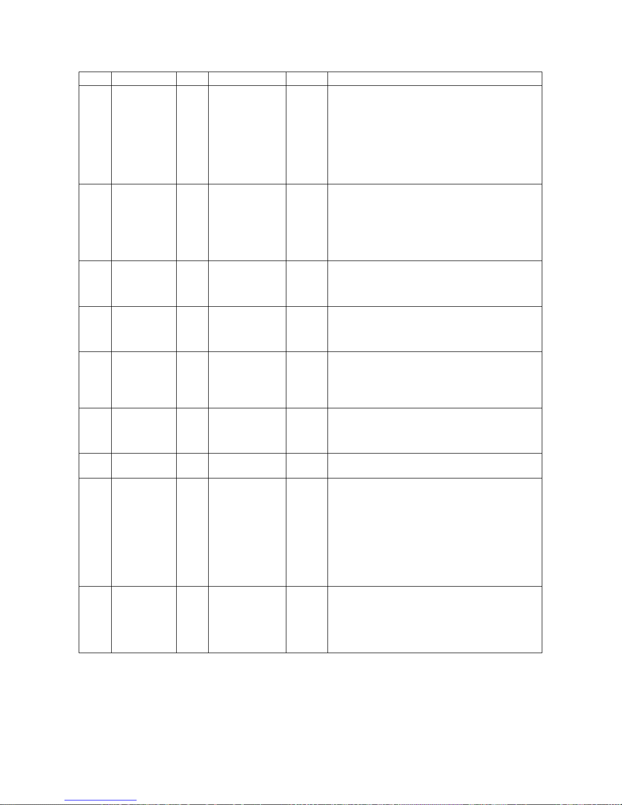
Drive Setup & Adjustments
Fnct # Description Units Range Default Extended Description
This setting affects the proportional gain and Phase
Margin of the regulator. Increasing this setting will
make the regulator more responsive to correct
mechanical load speed variances, but can cause it
42 Stability - 0.2 – 9.9 1.0
Weak Field
49
Current
Rated/Full
50
Field Current
51 Field L/R Sec 0.10 – 10.00 0.54
Rated Field
52
VDC
Standby Field
53
Current
Field
54
Response
Field Source
55
Volts AC
U/D Bit
63
Pickup
ADC 0.20 – 40.00 40.00
ADC 0.20 – 40.00 1.90
VDC 50 – 525 240
% 10 – 100 25
RAD 1.0 – 10.0 5.0
VAC 0 – 525 0
% 0.01 – 100.00 0.10
to amplify unwanted mechanical disturbances.
Reducing the setting value will provide smoother
operation but at the expense of time-delayed
reaction to velocity errors, particularly noticeable
when re-leveling.
Motor field current the drive should provide at rated
motor RPM. Set this value to produce rated motor
CEMF (no load voltage) at rated top speed. NOTE:
Motor field current will not exceed the setting of
Function #50. Setting or leaving this value at
default simply means that the field will not weaken
at high speeds.
Motor field current amperes the drive should
provide when starting and at low speed. It should
agree with Rated / Full / or Forcing Motor Field
Current per the motor nameplate.
Motor Field time constant, L/R. It is an important
value to determine motor field current regulator
gains. See Function #615 after performing the
Self-Tune procedure.
Rated Field Voltage necessary to produce Full field
amps Function #50. It is used to calculate motor
field circuit resistance and determine motor field
current regulator gains. Improper adjustment can
affect stability
This percent of the full field current amperes that
the drive should provide when the elevator system
is at rest (i.e. no Run command or Field Enable
command received).
Defines the desired motor field current regulator
bandwidth in radians per second.
This is the single-phase AC voltage used to power
the Field Rectifier module. The factory default
value of zero will let the drive automatically select
the same value as supplied for the nominal AC
voltage as set by Function #9. This conforms to
factory supplied wiring supplied at AC1 and AC2 on
the field interface PCB. Set this only if an external
transformer is used to supply a different voltage to
power the motor field circuit, set this value to the
nominal VAC provided at terminals AC1 and AC2.
Defines the zero speed threshold for detection of
motion via encoder measurement. It controls the
Moving-Up/Down, & Zero Speed detector output
signals, and determines when ARB will be turned
back ON if Function #130 is set to 2. Units are in
percent of rated speed.
62
Page 65
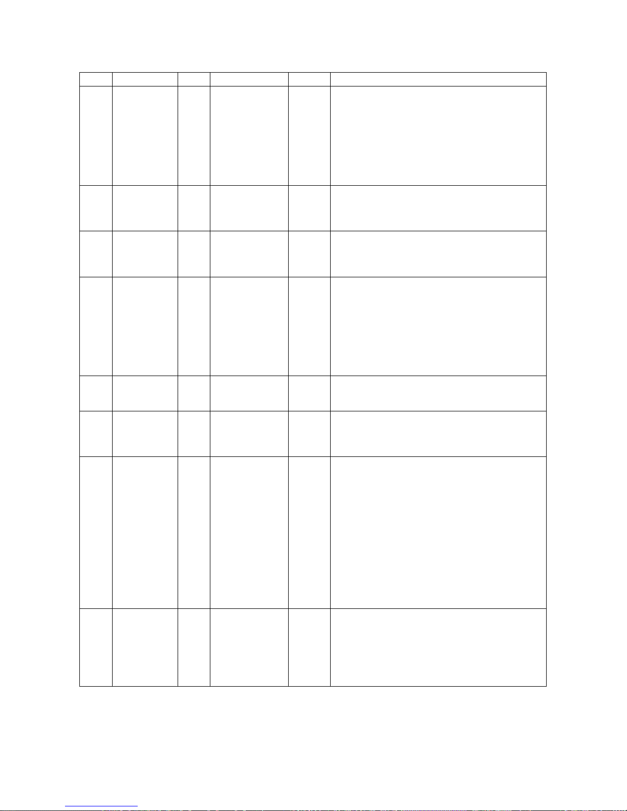
Drive Setup & Adjustments
Fnct # Description Units Range Default Extended Description
Sets the speed threshold where the At-Low-Speed
indicator will turn ON and OFF. This can be used
to indicate when the elevator is moving below the
Low Speed
64
Threshold
Over-Speed
80
Test
Over-Speed
81
Multiplier
Reference
82
Multiplier
Motor
83
Overload
Timeout
Motor
84
Overload
Level
85 I Decay Ramp Sec 0.01 – 2.50 0.20
Analog
Speed
86
Reference
Zero
% 0.1 – 100.0 2.0
Logic 0(Off) – 1(On) 0 (Off)
- 1.00 – 1.50 1.00
- -2.000 – 2.000 1.000
Sec 2.0 – 500.0 48.0
PU 0.50 – 2.00 1.15
PU -0.2000 – 0.2000 0.0000
door pre-opening speed. See programmable
output function F or M at functions 183 through
187. The adjustment value is percent of rated
maximum speed as set by Function #17.
Hysteresis is 5% of the set value.
This is a logic input that is used to activate an overspeed multiplier value, (Function #81). When
running the test increase F#12 to prevent the drive
from faulting on Overspeed (Fault 97).
Value of speed reference multiplier that will be used
to run an elevator over-speed test when Function
#80 is ON. This Function #also multiplies Function
#82.
Value is a multiplier for external analog or serial link
velocity references. It may be used to adjust the
actual calibration of the reference signals or to
cause the elevator to run at a different speed from
a +/-10 volt analog or other full-scale serial
reference command. The elevator will run at Rated
Speed (Function #11 and Function #17) from an
analog reference of 10V, when Function #82 is set
to 1.000, and Function #80 is 'OFF'.
This value shapes the motor overload time-out
curve.
Sets the threshold level where the motor overload
function will begin to operate. Sustained motor
current above this value will eventually cause an
overload trip according to the time set in #83.
Controls the rate of decay of motor armature
current during normal elevator stops. This helps to
prevent brake ‘thumping’ when the drive is shut
down and the brake is required to hold the car. The
drive Run logic command must remain active until
the elevator comes to a stop and the mechanical
brake is set. Armature current ramp-down will
begin after the RUN command is removed from the
drive. When the ramp-down is complete, the
contactor will be told to open. NOTE: The Drive
Enable command must remain ON and the elevator
Safety-Chain must remain closed until after the
contactor actually opens for this feature to work
properly.
At zero speed if the motor is creeping it may be
necessary to adjust this parameter to compensate.
Adjust this parameter until motion is stopped at
zero speed. After adjusting the low end of the
profile it may also be necessary to adjust the
reference at the top end of the profile. Refer to
Function #82 to set the speed reference gain.
63
Page 66
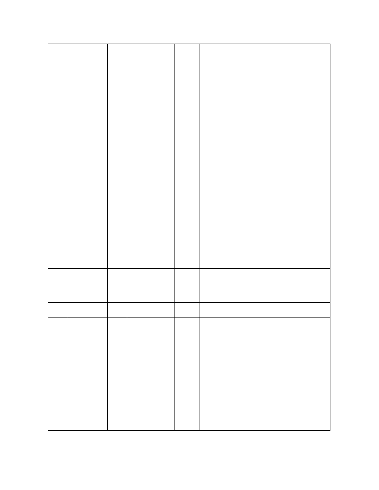
Drive Setup & Adjustments
Fnct # Description Units Range Default Extended Description
Multiplies the available pre-torque reference signal
for calibration adjustment. If this is set to 1.0, a +/10V analog signal or full-scale serial link signal will
cause 1 per unit (rated) armature current pre-torque
level.
Pre-Torque
87
Multiplier
DSPR Delay
88
Time
Brake Pick
89
Timer
Brake Drop
90
Timer
Must Stop
91
Timer
Brake Auto
92
Stop ON
Analog Out 0
93
Bias
Analog Out 1
94
Bias
Analog
95
Output 0
- 0.25 – 2.00 1.00
Min 0 – 60
Sec 0.5 – 5.0 1.0
Sec 0.5 – 5.0 1.5
Sec 0.1 – 5.0 2.0
Logic 0(Off) – 1(On) 0 (Off)
PU -1.00 – 1.00 0.00
PU -1.00 – 1.00 0.00
Logic 0 – 8 1
disabled
Analog
Determines the power OFF delay time for DSPR. If
0
set to zero (0), DSPR will be disabled. Power will
then remain ON at all times.
Adjusts the ON time for the Brake Pick relay to be
energized each time elevator brake lift should be
started. The internal velocity reference will remain
at zero during the Brake Pick time. Set to the
actual time to complete lifting of the brake to
prevent pulling through the brake during an elevator
start.
The time for the elevator brake to drop and set
when de-energized by the Lift and Pick relays.
Adjusts the time for the drive to keep holding the
car at zero velocity while the brake drops.
Establishes a limit on how long the drive may
continue to run after the Run command logic line is
released. This is a back-up means to cause the
drive to stop in case zero speed is not achieved for
any reason. Used only when elevator brake control
is engaged.
When ON, causes the controlled stop and Brake
sequence to commence when the speed reference
is set to zero...OR when the hardware Run logic
input is de-energized. A brake function output must
also be enabled.
Provides an offset adjustment for analog output
channel 0.
Provides an offset adjustment for analog output
channel 1.
Sets the specific analog output signal to be
observed at TB1-45 and TP41. Selections are:
The voltage measured will be a function of the
operating level of the parameter being displayed
and the signal multiplier Function #97. Signal
range is limited to and will saturate at ±10V.
Input
PreTorque
Voltage
Bias
10
(F#117)
0 = Trace Buffer 0
1 = Raw Speed Command
2 = Ramped Speed command
3 = Encoder Feedback
4 = Armature Current Reference
5 = Measured Armature Current
6 = Measured Armature Voltage
7 = Field current Reference
8 = Measured Field Current
PreTorque
(F#87)Mult
signal
drive
software
uses
64
Page 67
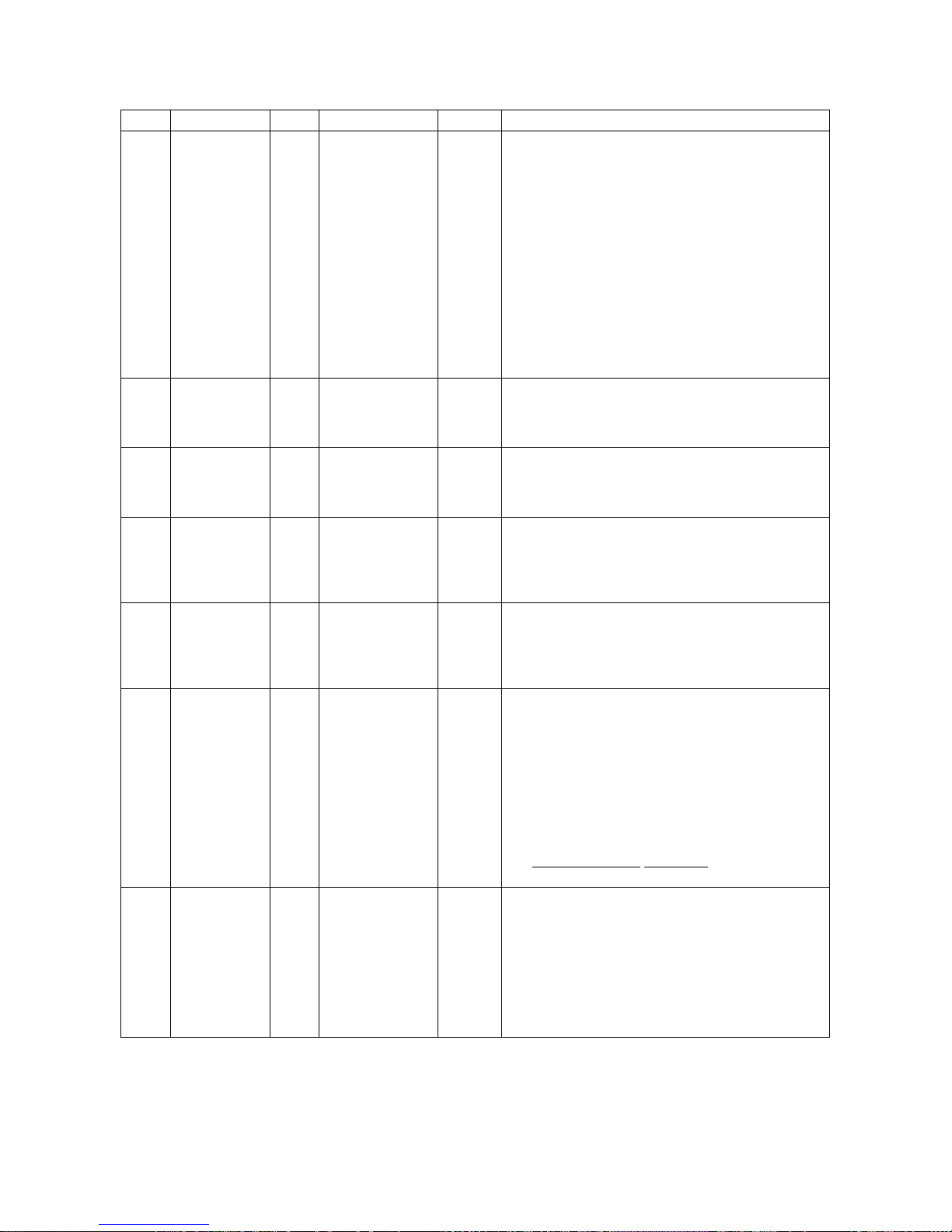
Drive Setup & Adjustments
Fnct # Description Units Range Default Extended Description
Sets the specific analog output signal to be
observed at TB1-46 and TP44. Selections are:
0 = Calculated CEMF
1 = Raw Speed Command
2 = Ramped Speed command
3 = Encoder Feedback
Analog
96
Output 1
Analog Out 0
97
Multiplier
Analog Out 1
98
Multiplier
Speed Error
99
Trip Time
Speed Error
100
Trip
Threshold
Auto Fault
101
Reset
3 Second
102
Loop Fault
Logic 0 – 8 3
PU 0.10 – 10.00 0.80
PU 0.10 – 10.0 0.80
Sec 0.20 – 5.00 5.00
% 0.0 – 100.0 100.0
Logic 0(Off) – 1(On) 0 (Off)
Logic 0(Off) – 1(On) 0 (Off)
The voltage measured will be a function of the
operating level of the parameter being displayed
and the signal multiplier Function #98. Signal
range is limited to and will saturate at ±10V.
Sets the specific multiplier value for Analog Output
#0. A value of 0.8 will set 8.0 volts of output for a 1
per unit signal, with some headroom to show overscale.
Sets the specific multiplier value for Analog Output
#1. A value of 0.8 will set 8.0 volts of output for a 1
per unit signal, with some headroom to show overscale.
Sets the time sensitivity of the Speed Error Trip
detection function. Speed errors larger than
Function #100, for longer than Function #99
seconds will cause a Speed Error Trip and
automatic drive shut down with Fault F410.
Sets the magnitude sensitivity of the Speed Error
Trip detection function. Speed errors larger than
Function #100, for longer than Function #99
seconds will cause a Speed Error Trip and
automatic drive shut down with Fault F410.
Allows the Drive to automatically reset drive faults
that caused a shutdown without an external Fault
Reset command. When turned ON, the drive will
attempt an automatic fault reset 5 seconds after the
fault occurs. If successful, the drive may then be
restarted. This feature is made inoperable by
setting Function #101 to 0 (off).
Note: A Fault count total is accumulated. One fault
count is removed from the total every 20 minutes.
An accumulation of 5 counted faults will cause fault
411 Maximum Resets Attempted and the need for a
manual reset for continued operation.
Selects the detection time for loop contactor faults.
These occur when the contactor acknowledge
feedback contact fails to open or close according to
the commanded state of the contactor coil driver.
Small contactors should operate within 450
milliseconds and should use the default value, 0, or
OFF. If large contactors are used with large hp
drives, set this value to ON to yield a 3 second fault
detection time.
4 = Armature Current Reference
5 = Measured Armature Current
6 = Measured Armature Voltage
7 = Field current Reference
8 = Measured Field Current
65
Page 68
Drive Setup & Adjustments
Fnct # Description Units Range Default Extended Description
Selects the source of the gain switch control to be
from local or serial link commands. If an analog
Serial Gain
104
Switch
Gain Switch
105
Speed
Tach Rate
107
Gain
Reference
110
Mode Select
Arched
Travel
111
Disable (Jerk
Abort)
Logic 0(Off) – 1(On) 1 (On)
PU 0.00 – 1.10 1.10
% 0.0 – 30.0 0.0
Logic 1 – 5 2
Logic 0(Off) – 1(On) 1 (On)
reference velocity or pre-set speed selects are
used, set this value to 0, off. If a gain switch will be
from the serial link, set this value to 1, ON.
[Function #104 on and Function #110 set for analog
or pre-set speeds results in no gain switching.]
This function is only used if Function #104 is off.
The value determines the speed where velocity
regulator gain is switched. If the speed reference is
below the value of Function #105, the closed loop
gain will correspond to that set by Function #40. If
the speed reference value is above set point
Function #105, then closed loop bandwidth will be
as set in Function #39.
This value adjusts the gain of differential
encoder/tach rate feedback. It can be useful to
help attenuate vibration and rope resonance
effects. Disable this function by setting the value to
zero. If using this feature, keep the setting as low
as possible consistent with good operation.
Allows the user to select the source of the velocity
reference signal.
Setting this value to 1 enables the drive to follow
the magnitude and direction polarity of an external
analog reference, and external ramp/slew limit rates
Function #21.
Setting this value to 2 (default) enables the 1 of 7
internal pre-set speed selects via Function #151
through 157 (preset speeds) and Function #170
through 181 (accel/decel, jerk rates). See also
Function #115 for direction control and Function
#150 for speed selects.
Setting this value to 3 enables serial link control of
the velocity reference, and external ramp/slew limits
rates of Function #21.
Setting this value to 4 enables a uni-polar analog
reference to be used with external direction logic
commands. External ramp/slew limit rates of #21
will also be used.
Setting this value to 5 enables serial link control of
the velocity reference, and Functions
#170,172,174,176 (accel/decel, jerk rates #1 only!).
Previously named Jerk Abort Enable. When ON,
changing the speed reference to a value less than
or equal the actual speed will cause the S-Curve
reference generator to immediately stop
acceleration, and begin to decel if appropriate.
When OFF, changing the reference to a lower
speed will cause a jerk-out (of any existing accel)
and jerk-in to a decel sequence. If done while
accelerating, Arched Travel will be the result.
66
Page 69
Drive Setup & Adjustments
Fnct # Description Units Range Default Extended Description
Setting this value to 0, off, enables the Armature
Voltage Feedback Mode to operate. This
parameter must be set to 1 for normal operation of
the drive. When in this mode the encoder
feedback monitor Function #601 will still be active
to allow for troubleshooting, however this signal will
not affect speed regulation. This mode is intended
for maintenance and troubleshooting only.
This parameter will control the speed, which the
motor will reach when operating in the Armature
Voltage Feedback Maintenance Mode. The theory
is the motor will operate up to this level of VDC if
given a 100% speed command. The speed can be
increased or decreased by either raising (Increase
Speed) or lowering (Decrease Speed) this number
or reducing (Increase Speed) or increasing
(Decrease Speed) Function #50 'Rated Field
Current'.
Setting this value to 1, on, enables the pre-torque
function to operate. The pre-torque value from the
analog pre-torque input will be multiplied by
Function #87 and used to pre-stress the velocity
error integrator to that armature current per unit
value upon starting. If Function #110 is set to 3 for
serial link control, the pre-torque reference input will
be from the serial link message. The adjusted pretorque value used at the start of an elevator run
may be viewed during the run via Function #603...If
pre-torque is not used, leave this function set to 0,
'OFF'.
Selects how the drive will determine the RUN
Direction when REF-MODE Function #110 is set for
internal pre-set speeds. When this is set to 0 (OFF)
24V relay logic input A1TB1-8 will be a Hardware
RUN command. A1TB1-50 will be the UP (Logic
low or OFF), or Down (+24V or ON) command.
When this is set to 1 (ON), 24 V relay logic input at
A1TB1-8 will be a Run-Up command A1TB1-50 will
be a Run-Down command. If REF-MODE Function
#110 is set to 1 or 3 for following bi-directional
external analog or serial link velocity commands,
the polarity of that signal will always be followed. In
that case, either A1TB1-8 or A1TB1-50 may be
used as a Hardware Run command input (but not
both).
When On, this control bit causes the decel ramp
rate active at the start of decel to remain in effect
until the decel sequence is completed. This
function will momentarily override logic input
commands at A1TB1-10 and A1TB1-51.
Used in conjunction with F#87, Pretorque Multiplier.
Analog
Input
Voltage
10
PreTorque
(F#117)
Bias
112
113
114
115
116
117
Encoder
Feedback
Enable
Armature
Voltage @
Max Speed
Pre-Torque
Enable
Run-Up/ RunDown Select
Decel Rate
Latch
PreTorque
Bias
Logic 0(Off) – 1(On) 1 (On)
VDC 0.0 – 650.0 100.0
Logic 0(Off) – 1(On) 0 (Off)
Logic 0(Off) – 1(On) 0 (Off)
Logic 0(Off) – 1(On) 0 (Off)
PU 0.00 – 1.00 0.00
PreTorque
(F#87)Mult
signal
drive
software
uses
67
Page 70
Drive Setup & Adjustments
Fnct # Description Units Range Default Extended Description
Sets the time sensitivity of the Speed- Error-is-Low
detector. This is a useful indicator to tell when/if
the drive is following the velocity reference properly.
Speed Error
120
Detect
Speed Error
121
Threshold
130 ARB Mode - 0 – 2 0
ARB
131
Bandwidth
ARB
132
Damping
ARB Speed
133
Threshold
Sec 0.0 – 5.0 0.5
% 0.0 – 15.0 2.0
RAD 1.0 – 15.0 6.0
- 0.01 – 20.00 2.00
% 0.0 – 10.0 0.0
Exceeding the set limits of this detector does not
shut the drive down. The detector results can be
sent to a logic output. See also, Function #99, 100,
121 and the description of logic outputs 183
through 187.
See Function #120. This value sets the magnitude
sensitivity of the Speed-Error-is-Low Detector.
Units are a percent of rated speed Function #17.
Selects between 3 possible Anti-Rollback operating
modes.
"0" to disable all Anti-Rollback features. Only E-
Reg will be engaged
"1" to enable Anti-Rollback when the drive is
started.
"2" to enable Anti-Rollback when starting the drive
and when the velocity again comes to a stop at the
next landing.
Determines the gain of the velocity and position
regulator when ARB is ON. This is the unity gain
crossover frequency in Radians/sec. Increasing
this setting will cause the position loop to respond
faster with less accumulated position error.
Adjusts damping of the position regulator when
ARB is ON. Increasing this setting will cause a
smoother but slower recovery of position error.
Reducing this setting will let ARB recover a position
error more quickly and abruptly.
Determines the reference speed where ARB will be
turned OFF and E-Reg will be engaged when the
drive is started, if Function #130 is set to 1 or 2.
This setting should be as low as possible to prevent
regulator transfer bumps when starting, but it must
be set high enough to remain engaged during releveling or to ignore a small analog zero reference
offset when using an external analog signal
reference. In percent of rated speed
68
Page 71
Drive Setup & Adjustments
Fnct # Description Units Range Default Extended Description
Determines the method for selecting pre-set
speeds from external relay logic applied to A1TB111, 12, 52, 53 and 54
Binary Speed Selects
S4 S3 S2 S1 S0 SPD # ADJ #nn
X X 0 0 0 ZERO NONE
X X 0 0 1 1 (151)
X X 0 1 0 2 (152)
X X 0 1 1 3 (153)
X X 1 0 0 4 (154)
X X 1 0 1 5 (155)
X X 1 1 0 6 (156)
X X 1 1 1 7 (157)
Binary /
Progressive
150
Pre-Set
Speed Select
Logic
0 (Progressive)
– 1 (Binary)
1
Table 8: Binary Preset Speed Selects
Progressive Speed Selects
S4 S3 S2 S1 S0 SPD # ADJ #nn
0 0 0 0 0 ZERO NONE
0 0 0 0 1 1 (151)
0 0 0 1 0 2 (152)
0 0 1 1 0 3 (153)
0 1 1 1 0 4 (154)
1 1 1 1 0 5 (155)
Table 9: Progressive Preset Speed Select
Note 1: When Progressive Speed Select mode is
used, any combination of S0-S4 not shown in Table
will result in zero speed being selected.
Note 2. When Reference Mode Select
#110) is set for Analog or Serial velocity reference
control, inputs S0-S4 have no affect.
See figure 12 on page 30.
(Function
69
Page 72
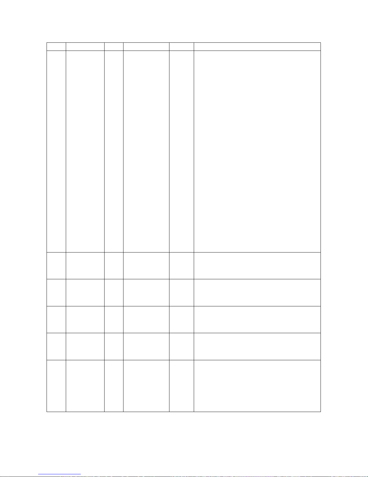
Drive Setup & Adjustments
Fnct # Description Units Range Default Extended Description
These function values specify the elevator car
speed for each individual pre-set speed setting.
The units must agree with that set for Rated Car
Speed in Function #17. [If feet per minute is used
at Function #17, then the units for Function
#151through 157 shall also be feet per minute.] No
value for Function #151through 157 should be
larger than that for Function #17. All values are
positive numbers. The selected reference speed
and direction will be determined by the setting of
Function #110, 115, 150, and 24V relay logic
inputs. It is certainly possible to connect the
selection of one or more pre-set speed logic input
control lines to also activate a different Ramp Rate
#2 or #3. See also the Decel Rate Latch, Function
#116. With careful thinking, one can obtain many
specific combinations of pre-set speeds and Ramp
Rates with a minimum of relay contacts.
Note 3: Switch select inputs S0-S4 are 24V logic
input signals available on A1TB1 with the following
assignments:
S0 = A1TB1-11
S1 = A1TB1-53
S2 = A1TB1-12
S3 =A1 TB1-54
S4 = A1TB1-52
Note 4: For S0 – S4...
+18 - 24VDC (ON) = 1
<5VDC (OFF) = 0
Note 5: Connecting A1TB1-10 to A1TB1-11 will
automatically select Ramp #3 with selection of preset speed #1.
Total acceleration time in seconds for S-curve ramp
#1 to occur from zero speed to rated elevator
speed. Effective only when internal pre-set speeds
are used.
Total acceleration time in seconds for S-curve ramp
#2 to occur from zero speed to rated elevator
speed. Effective only when internal pre-set speeds
are used.
Total deceleration time in seconds for S-curve ramp
#1 to occur from rated speed to zero speed.
Effective only when internal pre-set speeds are
used.
Total deceleration time in seconds for S-curve ramp
#2 to occur from rated speed to zero speed.
Effective only when internal pre-set speeds are
used.
The percent of time that will be spent in the
controlled jerk or S-portion of the timed ramp curve
during ramped acceleration #1. A percent S of
0.1% corresponds to almost all-linear acceleration.
A percent S of 100% will make the S-curve #1
smooth with no linear acceleration portion.
Effective only when internal pre-set speeds are
used.
151 –
157
170
171
172
173
174
Pre-Set
Speeds 1
through 7
Acceleration
#1 Time
Acceleration
#2 Time
Deceleration
#1 Time
Deceleration
#2 Time
Acceleration
#1 %S
- 0.0 – 1900.0 0.0
Sec 1.00 – 15.00 5.00
Sec 1.00 – 15.00 5.00
Sec 1.00 – 15.00 5.00
Sec 1.00 – 15.00 5.00
% 0.1 – 100.0 25.0
70
Page 73
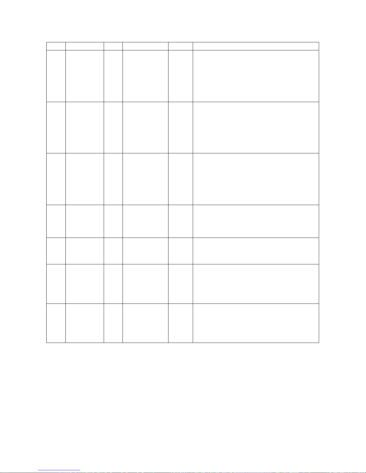
Drive Setup & Adjustments
Fnct # Description Units Range Default Extended Description
The percent of time that will be spent in the
controlled jerk or S-portion of the timed ramp curve
during ramped acceleration #2. A percent S of
175
176
177
178
179
180
181
Acceleration
#2 %S
Deceleration
#1 %S
Deceleration
#2 %S
Acceleration
#3 Time
Deceleration
#3 Time
Acceleration
#3 %S
Deceleration
#3 %S
% 0.1 – 100.0 25.0
% 0.1 – 100.0 25.0
% 0.1 – 100.0 25.0
Sec 1.00 – 15.00 5.00
Sec 1.00 – 15.00 5.00
% 0.1 – 100.0 25.0
% 0.1 – 100.0 25.0
0.1% corresponds to almost all-linear acceleration.
A percent S of 100% will make the S-curve #1
smooth with no linear acceleration portion.
Effective only when internal pre-set speeds are
used.
The percent of time that will be spent in the
controlled jerk or S-portion of the timed ramp curve
during ramped deceleration #1. A percent S of
0.1% corresponds to almost all-linear deceleration.
A percent S of 100% will make the S-curve #1
smooth but with no linear deceleration portion.
Effective only when internal pre-set speeds are
used.
The percent of time that will be spent in the
controlled jerk or S-portion of the timed ramp curve
during ramped deceleration #2. A percent S of
0.1% corresponds to almost all-linear deceleration.
A percent S of 100% will make the S-curve #2
smooth with no linear deceleration portion.
Effective only when internal pre-set speeds are
used.
Total acceleration time in seconds for S-curve ramp
#3 to occur from zero speed to rated elevator
speed. Effective only when logic input A1TB1-10 is
active. Selecting this ramp rate will override Rates
1 or 2.
Total deceleration time in seconds for S-curve ramp
#3 from rated speed to zero speed. Effective only
when logic input A1TB1-10 is active. Selecting this
ramp rate will override Rates 1 or 2.
The percent of time that will be spent in the
controlled jerk or S-portion of the timed ramp curve
during ramped acceleration #3. A percent S of
0.1% corresponds to almost all-linear acceleration.
A percent S of 100% will make the S-curve #3
smooth with no linear acceleration portion.
The percent of time that will be spent in the
controlled jerk or S-portion of the timed ramp curve
during ramped deceleration #3. A percent S of
0.1% corresponds to almost all-linear deceleration.
A percent S of 100% will make the S-curve #1
smooth with no linear deceleration portion.
71
Page 74
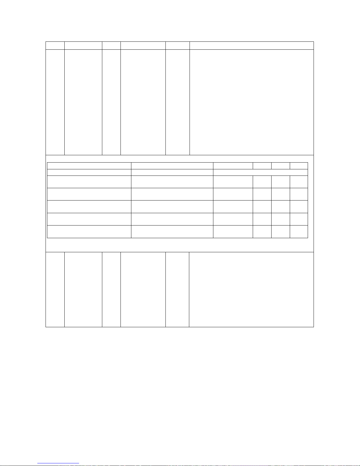
Drive Setup & Adjustments
Fnct # Description Units Range Default Extended Description
Alarms are classified as non-critical faults detected
by the DSD 412 that pose no immediate need to
stop operation. The Alarm output relay K2 (on the
Drive Control PCB, A1) is reserved for non-critical
fault indications. It has a normally open contact
wired to A1TB1-38 and 39). With Function #182
set to 0 (OFF), the default, relay K2 will pick-up,
closing the contact on the occurrence of a noncritical fault. With Function #182 set to a 1 (ON),
the relay will be picked-up during normal operating
conditions and drop out on the occurrence of a noncritical fault or Alarm.
Alarms are presently identified as drive overtemperature or thermistor failure, motor or
transformer thermostat over-temperature, and
motor overload trip. Other conditions may be
selectable to be alarms or critical faults.
182
Invert Alarm
Relay
Logic 0(Off) – 1(On) 0 (Off)
Output Circuit A1TB1 CONNECTION SELECTED FUNCTION
Output K3, Controlled by Function
#183 N.O. Relay
Output K4, Controlled by Function
#184 Open Collector Type
Output K5, Controlled by Function
#185 Open Collector Type
Output K6, Controlled by Function
#186 Open Collector Type
Output K7, Controlled by Function
#187 Open Collector Type
183-
Logic Output
187
Selects
Logic
FUNCTION SELECT SETTING 1 (DEFAULT) 2 3 4
A1TB1-36&37
A1TB1-78
A1TB1-79
A1TB1-83
A1TB1-84
A
B
C
D
E
F
A
G
J
F
Table 10: Programmable Output Selections
The function of relay and open-collector logic output
channels, K3-K7 on the Drive Control PCB, are
programmable. Each output has several choices of
functions. The descriptions below identify how
See Table 10:
Programmable
Output
Selections
each option works. Table 10: Programmable
Output Selections identifies how to map a particular
1
function to a particular output channel. [For
example to program output K6, A1TB1-83 to
indicate when the drive is at zero speed, option “J”,
set Function #186 to be “2”.] The factory default
values (1) will program K3-K7 to the same function
as older software SA274.
C
G
H
K
I
N
P
I
L
M
72
Page 75
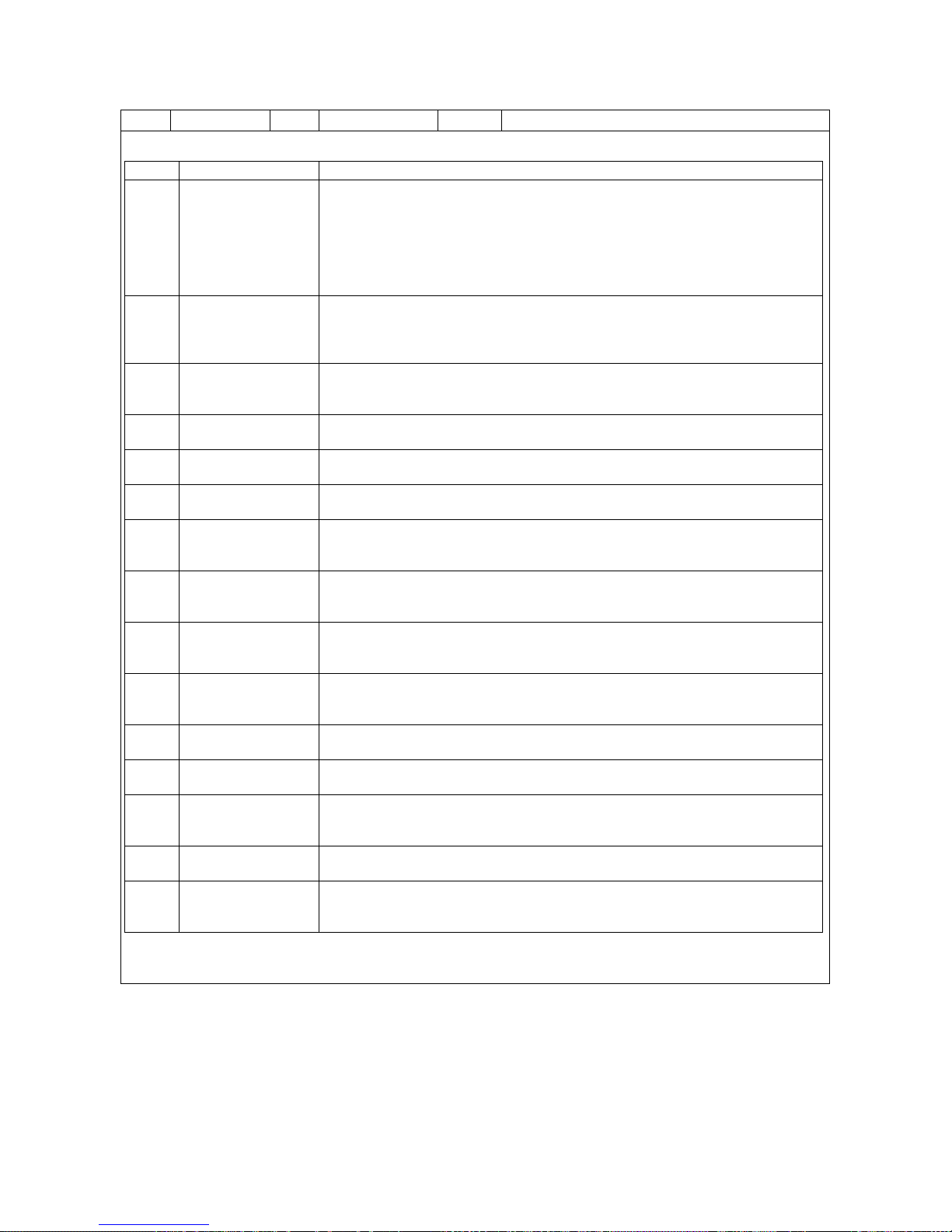
Drive Setup & Adjustments
Fnct # Description Units Range Default Extended Description
Setting Desc. Extended Description
Relay K3 is picked during normal operating conditions with N.O. contact closed.
Relay K3 drops and contact opens if measured motor field current ever exceeds
Excessive Field
A
Current
High CEMF or Low
B
Line
C Run Engaged
D Moving Up
E Moving Down
F Low Speed
G Field is UP
H Speed Error is Low
I Speed Error is High
J Zero Speed
K Moving
L Lift Brake
M High Speed
N Brake Pick
P DSPR Control
125% of Rated Field current, Function #50. When programmed to control output
K4, the output will be active during normal operation, and become inactive if
motor field current ever exceeds 125% of Rated Field current, function #50.
This function can be used as a warning of a malfunction condition that could
cause damage to the motor field.
Active if motor CEMF becomes greater than 1.09 X drive VAC input, or if VAC
input falls below 0.9 X Rated VAC, Function #9. This is a warning indication that
there may be problems associated with too much CEMF or a drooping power
line.
Active when the drive speed regulator is in operation. Inactive during armature
current ramp-down or if the contactor is open. May be used as an indication that
the drive is in control and that the elevator brake may be released.
Output becomes active when encoder velocity is greater than the setting of
function 63 in the UP direction. May be used to verify proper car direction.
Active when encoder velocity is greater than the setting of Function #63 in the
DOWN direction. May be used to verify proper car direction.
Output becomes active when encoder speed is less than the setting of Function
#64. May be used to indicate low speed for door pre-opening logic.
Active when motor field current has risen above the threshold value
programmed in Function #32, or drive is in operation. May be used to indicate
when the drive Start command will function without delay.
Active when Speed Error is less than Function #121 for longer than Function
#120 seconds. May be used to indicate that the drive is correctly following the
programmed velocity profile.
Active when Speed Error is greater than Function #121 for longer than Function
#120 in seconds. May be used to indicate that the drive is not following the
programmed velocity profile. This is the opposite logical state of H.
Active when encoder speed is below the setting of Function #63 in either
direction. May be used to indicate that deceleration is complete and the brake
may be set without any bumps.
Output becomes active when encoder speed is greater than the setting of
Function #63 in either direction. This is the opposite logical state of J.
Output K6 becomes active when elevator brake should be lifted. Will deenergize when the brake should be dropped.
Output becomes active when encoder speed is greater than the setting of
Function #64 in either direction. This is the opposite logical state of F. May be
used to prevent or enable door pre-opening logic.
Output K3 becomes active for time Function #89 each time a Brake Lift
sequence is started. Will be de-energized when the brake should be dropped.
Output K4 is active to pull in an external power control relay when the drive is
supposed to be powered up for operation. Output becomes inactive after a
DSPR time delay time-out. See Function #88.
73
Page 76
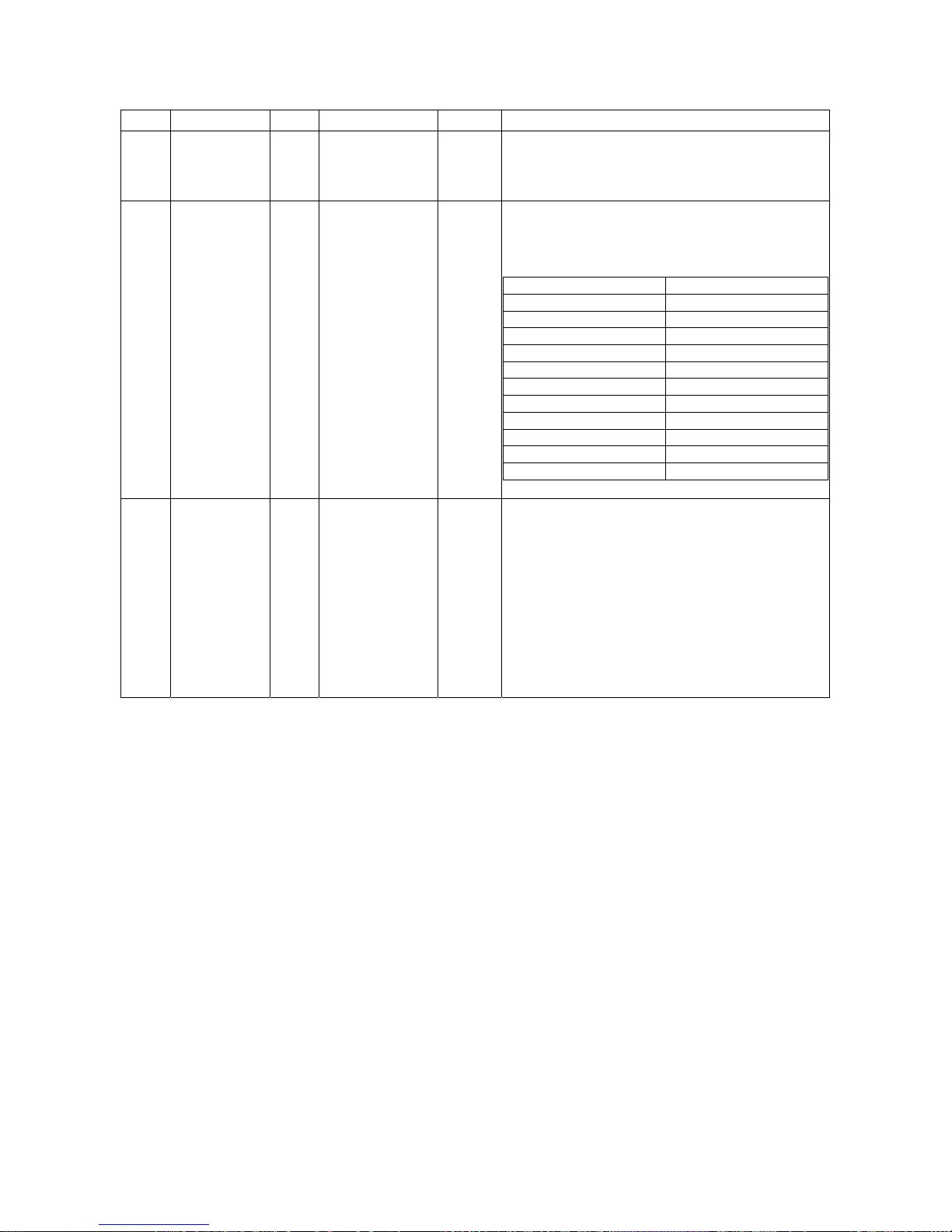
Drive Setup & Adjustments
Fnct # Description Units Range Default Extended Description
Controls the depth of the notch filter used for a rope
190 Notch Depth - 0 – 10 0
191 Notch Period - 0 – 10 7
F413 Detect
192
Level
PU 0.05 – 0.50 0.05
resonance counter-measure. When set to zero, the
filter is not active. Increase the setting toward 10
as required to suppress system resonance.
Controls the center frequency of the rope
resonance notch filter. This is not a continuous
adjustment as the frequency is selected in steps as
in Table 11: Notch Period Steps
ENTRY NUMBER NOTCH FREQ
0 100 Hz
1 50
2 33
3 25
4 20
5 17
6 14
7 12
8 11
9 10
10 9
Table 11: Notch Period Steps
Sets the level of difference of the field current
reference and the feedback at which the drive will
display the F413 warning. If all of the criteria is
correct in the field circuit and in the parameter
setup the F413 warning should not appear. The
tracking error can be monitored on F620. If the
error is out of tolerance due to low or sagging line
voltage and the issue cannot be resolved increase
this parameter to eliminate the warning. This level
is in PU where #50 rated field amps = 1.0PU i.e.
0.05 would correlate with 5% difference between
the feedback and the reference.
Table 12: Adjustment Function Descriptions
74
Page 77
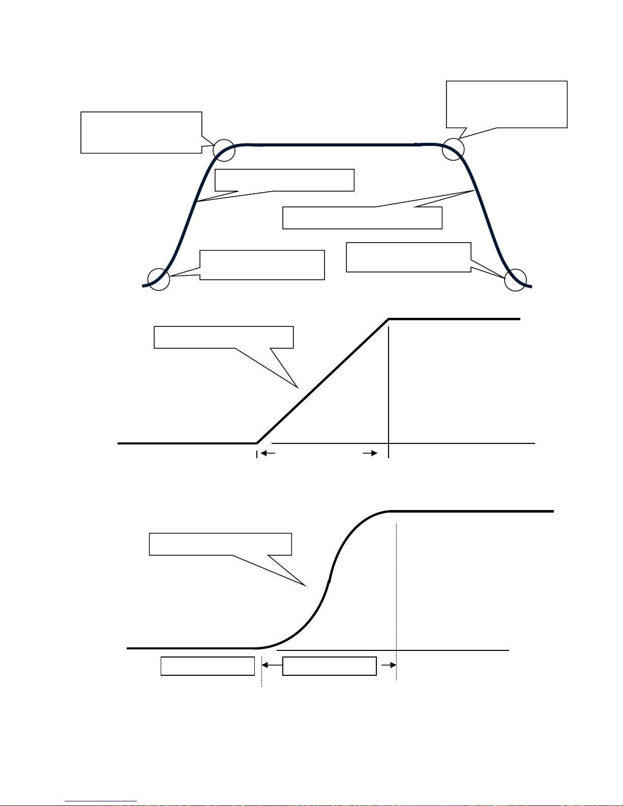
J
J
CONTROLLED
ACCEL JERK OR ‘S’
PORTION
#174, #175, #180 =0.1%
LINEAR ACCEL REGION
LINEAR DECEL REGION
CONTROLLED ACCEL
ERK OR ‘S’
Figure 20: S-Curve Accel/Decel Cycle
CONTROLLED DECEL
ERK OR ‘S’
Drive Setup & Adjustments
CONTROLLED
DECEL JERK OR ‘S’
PORTION
FULL SPEED
ZERO SPEED
Figure 21: S-Curve Accel with minimum %S
#174, #175, #180 = 100%
ACCEL TIME
FULL SPEED
Figure 22: S-Curve with 100% S
75
Page 78
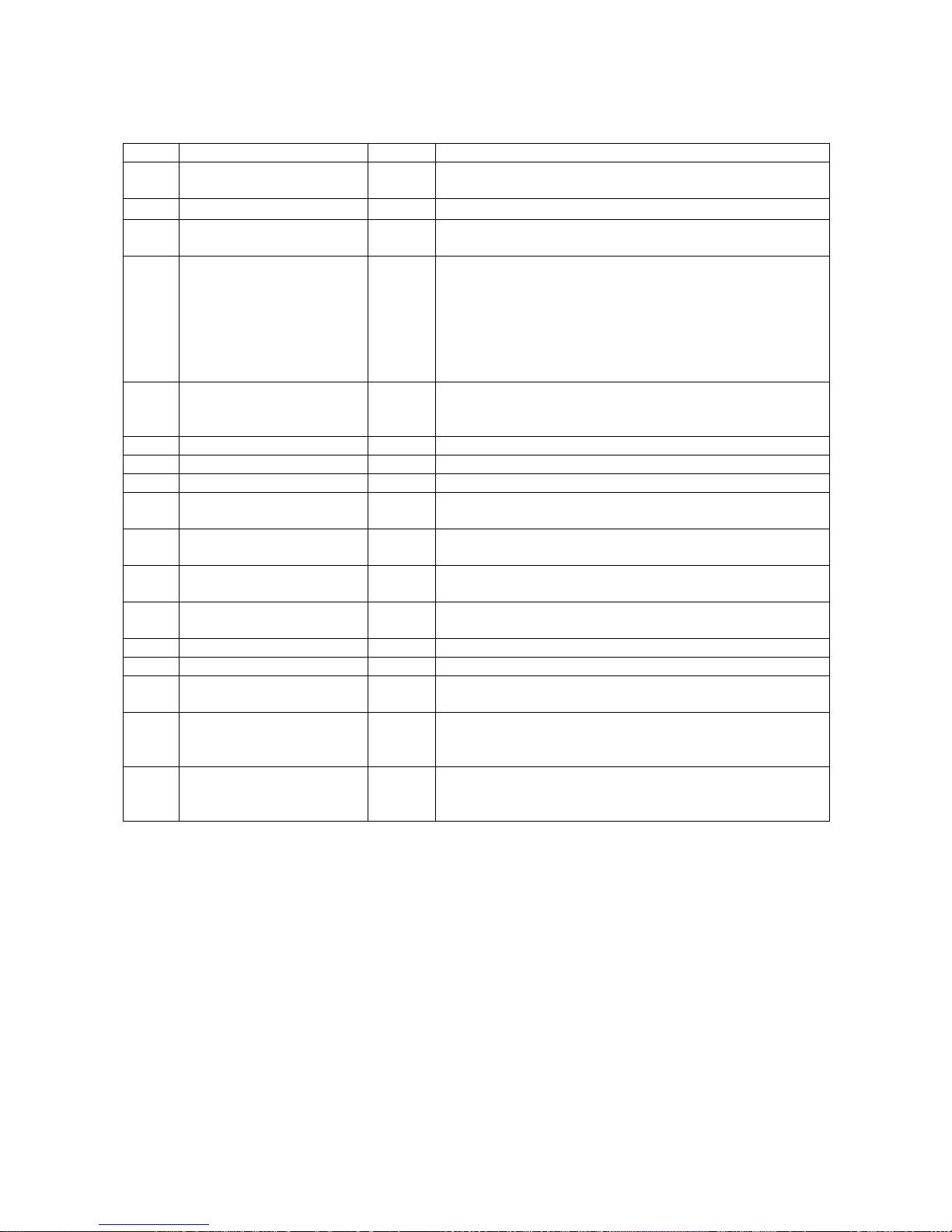
Drive Setup & Adjustments
Display Monitor Functions
Fnct # Description Units Extended Description
600 Car Speed 601 Motor Speed RPM
602
603 Pre-Torque Input %
609 CEMF VDC VDC
610 Motor Armature Voltage VDC
611 Motor Armature Current ADC
612 Motor Field Current ADC
613
614
615
616 Speed Error %
617 AC Line Frequency Hz
618 Heatsink Temp °C
619 AC Line Voltage V RMS
620 F413 Tracking Level PU
621
Dictated Speed
Reference
Measured Motor
Resistance
Measured Motor
Inductance
Measured Field L/R
Time Constant
Serial Communication
Control Enabled
Ohms
Henry
Sec
Logic
Measured velocity of the elevator. Units are as set in
function 17.
Measured elevator motor RPM.
Reference velocity after accel/decel rate control
-
conditioning. Units are as set in function 17.
This display is the pre-torque reference as applied to
starting the velocity regulator. The value is latched to
display the pre-torque value used at the start of a run.
Prior to a start, the displayed value is that of the analog
or serial link input. This function works only when pretorque enable control, functions 114 is turned ON. Units
are a percent of Rated Motor Amps.
This display is the CEMF of the motor calculated from
measured motor voltage, current and armature circuit
resistance functions 4.
Measured voltage output to the motor armature circuit.
Measured drive output to the motor armature circuit.
Measured motor field current.
Measured motor armature circuit resistance calculated
during self-tune.
Measured motor armature circuit inductance calculated
during self-tune.
Motor field time-constant measured during self-tune.
This displays the difference between the speed
reference and speed feedback.
Measured frequency of the 3-phase AC line.
Measured heat sink temperature of the drive in °C.
This display is the measured 3-phase AC input line-line
voltage.
The difference between the Field Current reference and
the Feedback. F413 warning will result if higher than
F192 for 5 seconds.
This logic will be ON if RS422 (or RS232) control
communications is enabled for drive control. Does not
include use of PCDU.
76
Page 79
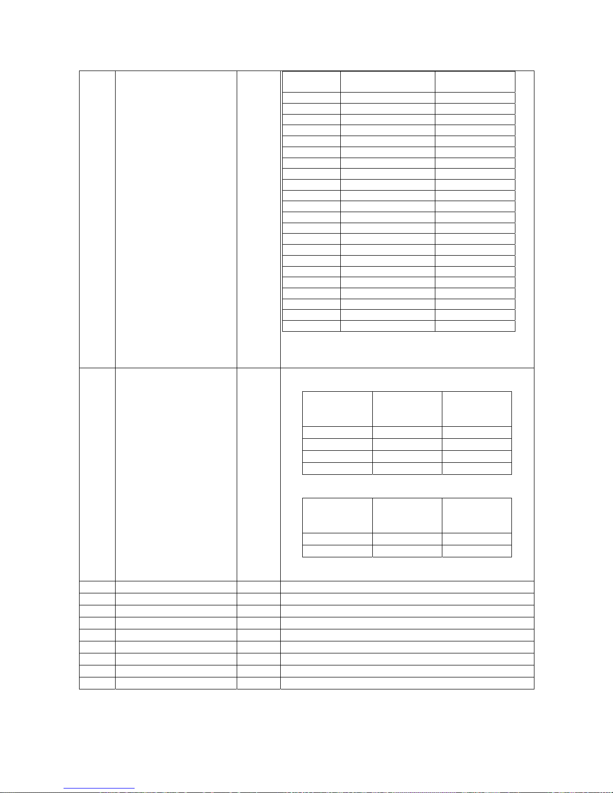
688 Cube I.D. -
689 Field Range -
Drive Setup & Adjustments
Cube I.D.
No.
1 002, 003 525
3 005, 007 525
6 010, 015 525
9 020, 025, 030 525
12 040, 050, 060 525
15 075, 100, 125 525
18 150 525
21 200 525
24 250 525
28 300 525
31 400 525
34 500 525
37 600 525
40 700 525
43 800 525
44 040, 050, 060 600
45 075, 100, 125 600
46 200 600
47 300 600
48 400 600
49 600 600
50 800 600
*** This number should agree with the DSD 412 drive data
nameplate.
FIELD CURRENT RANGE (2 - 200HP)
Indicates actual SW1 setting
#689 SW1
Read-Back
1 0.2 1.9
3 7.0 16.0
6 2.0 6.9
8 16.1 40.0
FIELD CURRENT RANGE (250 - 800HP)
Indicates actual SW1 setting
#689 SW1
Read-Back
3 2.0 16.0
8 16.1 40.0
HP 53ST*** Max Input VAC
Table 13: Cube I.D. Number
Minimum
Rated Field
Amps DC
Minimum
Rated Field
Amps DC
Maximum
Rated Field
Amps DC
Maximum
Rated Field
Amps DC
690 U13/U14 “97SAXXX” 691 PCU Release 692 Day 693 Month 695 Year 696 Beta “P” 697 U39/U40 “97SAXXX” 698 DCU – Revision 699 Customer Version I.D. -
Table 14: Field Current Range
-
-
-
-
-
-
-
-
-
Table 15: Display Monitor Functions
77
Page 80
Drive Setup & Adjustments
Miscellaneous Functions
FNCT. # DESCRIPTION REFERENCE PAGES
22 CLEAR ERRORS LIST
000 VIEW FAULT LIST
800 VIEW ERROR LIST
801 FAULT/ERROR ACTIONS See Error Reporting on page 33.
980 TRACE MONITOR -
981 VERIFY I/O
993 CLEAR NVRAM
994 SAVE/RECALL FUNCTION
995 LOAD DEFAULTS
997 SELF TUNE
998 PCU DIAGNOSTICS
Table 16: Miscellaneous Functions
See Input – Output Signal
Verification on page 89.
See Non-Volatile Ram Access
See Non-Volatile Ram Access
See Self Tune Function on page
See Power Conversion
Diagnostics on page 39.
-
-
-
on page 36.
on page 36.
37.
78
Page 81

Drive Faults
Drive Faults
The following Faults are custom to the SA407
Generation 2 DSD 412 software.
Function Error Code Listing
*** DCU ERRORS ***
DISPLAY # - DESCRIPTION
13 = ILLEGAL INSTRUCTION
14 = LINE 1010 EMULATOR
15 = LINE 1111 EMULATOR
16 = PRIVELEGE VIOLATION
17 = DIVIDE BY ZERO
21 = WATCHDOG TIMEOUT
22 = RESERVED INTERRUPT
23 = UNINITIALIZED INTERRUPT
24 = TRACE EXCEPTION
26 = SPURIOUS EXCEPTION
97 = OVERSPEED TRIP
98 = TACH/ENCODER LOSS
99 = REVERSE TACH/ENCODER
100 = NOT A NUMBER
101= MATH OVERFLOW
102 = MATH UNDERFLOW
103 = FLOATING POINT DIVIDE BY ZERO
104 = SIGN ERROR IN SPEED REG
112 = BAD PCDU POINTER
113 = MISSING PCU
114 = LOCKED UP QUEUES
115 = MULTIPLEXER CONFIG. ERROR
117 = 20 SEC COMM. START FAULT
118 = 150 MSEC COMM. MSG FAULT
220 = DCU ROM BUS ERROR
221 = DCU RAM BUS ERROR
222 = DCU NVRAM BUS ERROR
223 = DCU DPRAM BUS ERROR
232 = UNKNOWN BUS ERROR
240 = DCU ROM BUS ERROR
241 = DCU RAM ADDRESS ERROR
242 = DCU NVRAM ADDRESS ERROR
243 = DCU DPRAM ADDRESS ERROR
252 = UNKNOWN ADDRESS ERROR
***DRIVE FAULTS/ERRORS***
DISPLAY # - DESCRIPTION
400 = MOTOR OVERLOAD
401 = EXCESSIVE FIELD CURRENT
402 = CONTACTOR FAULT
403 = 5-MIN FULL FIELD FAULT
404 = OPEN ARMATURE CIRCUIT FAULT
405 = SAFETY CIRCUIT FAULT
406 = 10% LOW LINE ALARM
407 = EXCESSIVE DCU CEMF ALARM
408 = EXCESSIVE PCU CEMF FAULT
409 = UNEXPECTED PCU RESET
410 = SPEED ERROR FAULT
411 = MAX AUTO-RESETS ATTEMPTED
413 = FIELD CURRENT TRACKING FAULT
414 =
SOFTWARE COMPATABILITY FAULT
*** PCU ERRORS***
DISPLAY # - DESCRIPTION
900 = PCU LOOP FAULT
901 = PCU IST FAULT
902 = POWER SUPPLY FAULT
903 = LINE SYNC FAILURE
904 = LOW LINE FAULT
905 = FIELD LOSS
906 = DCU FAILURE
907 = THERMISTOR FAULT
908 = OVER TEMPERATURE
909 = EXCESSIVE RIPPLE
910 = BLOWN FUSE
911 = SHORTED SCR
912 = OPEN SCR
915 = PARAMETER SETUP FAULT
916 = FORCING FAULT
917 = REVERSE ARM. V. FEEDBACK
919 = RATED VAC. SETTING ERROR
920 = RATED ARM. VOLT. SETTING
921 = BRIDGE RATING FAULT
923 = RATED ARM. I. SETTING ERROR
924 = RATED FIELD I. SETTING ERROR
925 = FIELD PCB SENSE FAULT
926 = PCU WATCHDOG TIMEOUT FAULT
929 = FIELD CURR. WON’T GO TO ZERO
930 = FIELD CURR. WON’T GO TO RATED
931 = OPEN CIRCUIT CEMF FAULT
932 = CLOSED CIRCUIT CEMF FAULT
933 = ARM CURRENT WON’T INCREASE
934 = LOW ARM INDUCTANCE
935 = WRONG BUS VS ARM VOLTS FBK
936 = E-STOP OPENED DURING TEST
937 = LOW ARMATURE VOLTS FBK
938 = LOW BUS VOLTS FBK
939 = FIELD FB HARDWARE FAILURE
940 = FIELD A/D OVERFLOW FAILURE
941 = MOTOR THERMOSTAT OPEN
Prot = CORRUPTED NV RAM DATA
79
Page 82
Drive Faults
Troubleshooting
ERROR/FAULT
CODE
400
401
402
403
404
405
406
407
PROBABLE CAUSE/ — CORRECTIVE ACTION
MOTOR OVERLOAD FAULT --- Indicates that the drive has delivered excess
motor amps for a significant period of time.
Refer to #83 and #84 for proper set-up.
Check for dragging elevator brake or weakened motor field.
A motor overload fault does not automatically shut down the drive, but is
annunciated via the ALARM relay output K2. See #182
EXCESSIVE FIELD CURRENT --- Indicates that measured motor field current
exceeded 125% of rated current #50. – Causes:
Partially shorted motor field coil. Check motor field.
Wrong data entry causing unstable motor field current regulator. Review and
verify settings for #49, 50, 51, 52, 54, & 55.
Mis-wiring of module A3. Verify that phasing is correct.
Wrong current tap at A3, TB4, or A3 SW1 setting. Verify.
Malfunction of motor field power circuit. Check module A3.
LOOP CONTACTOR FAULT— The Loop Contactor auxiliary contact does not
pick up or drop out within the designated time as requested by the DSD 412
drive. See #102. – Causes:
Defective Loop Contactor Aux. Check for proper feedback at TB1-7.
Defective Contactor. Check for open coil or mechanical binding.
Defective Pilot Relay LPR.
Interference from other elevator relay contact circuits.
FIVE-MINUTE FULL FIELD – Indicates that the Drive and Field Enable control
circuit at TB1-9 was active for 5 minutes without starting the drive. This can
cause motor field burnout. Check car controller relay logic.
OPEN ARMATURE CIRCUIT – A large current error existed for ½ second.
Check the DC link fuse F4.
Check motor armature circuit wiring.
Check power poles in the DC loop contactor.
SAFETY CIRCUIT FAULT—The Drive has detected that the Safety Circuit wired
between TB3-1 and TB3-6 on the Power supply opened unexpectedly while the
drive was in the run mode. The safety chain must be closed at least 100ms prior
to enabling the drive. Check for intermittent connections in the Safety Chain.
LOW LINE ALARM – Indicates that the input AC line voltage sagged more than
10% below nominal line volts as set at #9. This does not shut down the drive but
may be an indication that work is needed to avoid future Low Line shut down
faults, F904.
DCU CEMF FAULT - The CEMF of the motor exceeded 109% of measured AC
input voltage to the Drive. This is a warning only and does not cause an
automatic drive shut down. – Causes:
3 Phase Input AC Line Voltage drooped or is too low.
CEMF on motor rises above VAC input voltage.
Motor field current set too high. Verify weak field set point #49 Vs desired
motor voltage at top speed.
Check & correct motor field control tuning to prevent CEMF overshoot.
Review and verify settings for #49, 50, 51, 52, 54, & 55.
80
Page 83
ERROR/FAULT
CODE
408
409
410
411
413
414
13-17, 21-26,
100-104, 112-114,
220-234, 240-254,
926
117 / 118 SERIAL COMMUNICATION FAULT
PROBABLE CAUSE/ — CORRECTIVE ACTION
PCU CEMF FAULT - The CEMF of the motor exceeded 118% of the rated VAC
input voltage to the Drive. This fault causes a drive shut down to prevent fuse
blowing. – Causes:
3 Phase Input AC Line Voltage is low. Check and correct.
Incorrect motor field current setting or field regulator miss-operation causing
excessive CEMF. Check & correct.
Excessive drive speed overshoot. Correct with velocity regulator
adjustments.
Check and correct motor field control dynamic tuning to prevent CEMF
overshoot. Review and verify settings for #49, 50, 51, 52, 54, & 55.
PCU RESET — PCU processor was unexpectedly reset. Verify that correct PCU
software and revision level is being used. Possible problem with main circuit card
hardware. Look for external noise interference. Ensure that equipment and
signal grounding connections are proper. Correct as necessary. If problem
remains, replace Drive Control PCB.
SPEED ERROR TRIP FAULT --- Indicates that a large speed error existed for a
significant period of time. Look for dragging brake or weak motor field. See the
explanations for #99 & #100.
MAX AUTO-RESETS ATTEMPTED --- Indicates that more than 5 automatic
resets were necessary in less than 20 minutes of accumulated time. See the
explanation for #101.
FIELD CURRENT TRACKING FAULT --- Indicates that the ACTUAL field current
is failing to track the field current COMMAND by more than F192 (Default = 0.05)
for 5 seconds. This is not a shut down fault.
Check AC voltage on AC1 and AC2 – Typically 1.5 to 2.5 times VAC (min),
where VACmin = VDC/0.9 or (Full Fld Amps * Field resistance)/0.9
Drives not using correct self-tune values and/or field response set incorrectly.
3. Monitor F620 Fld Trkg Diff, it should be less than F192 "F413 Detection
Level". By setting F192 higher it can eliminate this warning, Caution should
be observed prior to doing this. If the proper conditions exist the data on F620
display should not exceed 0.05PU for over 5 seconds.
SOFTWARE COMPATABILITY FAULT --- Indicates that the PCU (U13, U14)
Version and or Revision won’t operate with the DCU (U39, U40) installed in the
drive.
Contact Magnetek
MISC FAULTS - Problem with either hardware or software on the Drive Control
PCB. See list at Section 4.5.
Check and/or replace U13, U14, U39, U40 (EPROM’s).
Replace Drive Control PCB A1.
117 = Serial comm. not started within 20 seconds after drive reset or power up.
118 = Valid serial comm. message not received for more than 150 MS.
Ensure that host is connected and sending valid messages.
Look for and correct electrical grounding noise interference problem.
If Serial comm. is not being used do not set #110 to selection 3.
Drive Faults
81
Page 84
Drive Faults
ERROR/FAULT
CODE
97
98
99
900
901
902
903
904 LOW LINE VOLTAGE FAULT
PROBABLE CAUSE/ — CORRECTIVE ACTION
OVERSPEED FAULT - The motor speed has exceeded the trip level set in
function #12, as measured by the encoder. #12 is a percentage of the motor
speed value set in #11. Possible cause
Incorrect setting of #10, #11 or #12.
Poor speed regulator tuning - Check #40, 41 & 42
Velocity reference set above rated speed.
Intermittent velocity encoder.
TACH LOSS FAULT - The drive does not see the encoder velocity in proportion
to armature voltage indication of speed. Refer to Function explanations for #14
and #15.
Ensure that the encoder is working. Look for loose connections.
Raise the value for #14 if motor has high resistance.
Ensure that the contactor feedback circuit at A1TB1-7 does not close before
the armature power poles. See timing diagram on page 49.
REVERSED TACH FAULT — The digital encoder and motor voltage signals do
not agree in direction of rotation. Probable cause: Encoder leads are reversed.
Reverse connections for A and A/NOT.
PCU LOOP FAULT - The contactor did not close or opened unexpectedly. Or
the motor voltage exceeded 30% of rated motor voltage #7 during Self-Tune
#997. When this occurs, the Severe Fault flag is set and the DSD 412 current
reference is forced to zero. This fault will shutdown the drive.
Check the contactor aux feedback circuit to TB1-7.
Check contactor and LPR coils for proper operation.
Check that power is being applied to LPR from the power supply at TB3- 5.
(Will be momentary until F900 occurs.) If not there, suspect an internal relay
failure. Replace A4, Power Supply PCB.
PCU IST FAULT – Current flow in excess of 300% of rated armature current
detected. Check for:
Ground fault or intermittent connection in motor armature circuit.
Faulty current measuring module.
Poor current regulator tuning.
POWER SUPPLY FAULT (CPU Reset Required)
The Low Voltage Power Supply (A4) output has dropped below 60% of the rated
voltage. This fault will shutdown the drive. Possible causes:
Loss of 115VAC power.
Short circuits in +5V, +/-15V, or +24V circuits, possibly external to the drive.
Failed Power Supply
Blown fuse internal to power supply.
LINE SYNCRONIZATION FAULT (CPU Reset Required)
The Phase Locked Loop has lost synchronization with the 3 Phase AC input
power supply. When this occurs, the Severe Fault flag is set and the current
reference is forced to zero. Generally this is caused by AC input power problems
and is self-correcting. This fault will shutdown the Drive.
This fault will often occur with a F904 fault.
The AC input power has dropped below 80% of the Nominal AC Line Voltage #9
for 3 consecutive cycles or lower than 50% for one cycle. When this occurs, the
Severe Fault flag is set and the DSD 412 current reference is forced to zero. This
fault will shutdown the Drive.
82
Page 85
ERROR/FAULT
CODE
905
906
907
908
909
910
911
912
Drive Faults
PROBABLE CAUSE/ — CORRECTIVE ACTION
FIELD LOSS FAULT This fault will shutdown the Drive.
The field current feedback has dropped below 80% of the expected current during
the following conditions:
#49 when Drive is in Field Weakening Mode (Top speed).
#50 when Drive is in Full Field Mode (Accel or Decel).
#53 when Drive is in Standing Field Mode (not running).
Probable causes are:
Open circuit failure of motor field or motor field wiring.
Hardware failure of motor field control circuitry.
Loss of power or incorrect phasing to Field Rectifier.
DCU FAILURE FAULT (DSD 412 Power down is required.)
The update of the Dual Port RAM from the Drive Control Unit (DCU) is unreliable.
This requires the replacement of the Drive Control PCB, A1. This fault will
shutdown the drive.
THERMISTOR FAULT The thermistor is found to be open or shorted. Check
and/or replace the thermistor. It should measure between 2K – 10K ohms at 20C
room temperature. A Thermistor Fault will also occur if the machine room
ambient temperature is below 0C as the resistance it detected is too high to be
measured. An open thermostat on larger drives will also indicate F907. This fault
will not shutdown the Drive.
OVER TEMPERATURE FAULT - The calculated SCR junction temperature is
above 125 degrees Centigrade. This is calculated from the thermistor heat sink
measurement and measured armature output current heating effects of SCRs.
Possible causes:
Ambient temperature too high. Check for cause.
Clogged air filter in cabinet. Clean or replace air filter.
Clogged heat sinks. Clean Heatsink fins.
Cooling fan failure. Replace defective cooling fan(s) in power cube.
Note: This fault will not shutdown the Drive.
RIPPLE FAULT - Repeated high peak to average motor armature current. The
cause of this condition may be defective hardware that can be discovered
through the PCU Diagnostics CDU function, #998. It may also occur due to poor
regulator tuning or other oscillatory operation condition.
BLOWN FUSE FAULT - One or more of the three AC line fuses is open. This
condition is checked on power-up and upon request through the PCU F#998 PCU
Diagnostics function. Detection is accomplished by measurements via voltage
dividers on the Armature Interface PCB, A2. Possible causes are;
One or more of AC input fuses are blown.
Power wiring problem-check wiring.
Faulty DSPR power relay.
SHORTED SCRS/DOUBLER FAULT (DSD Power Down is required.)
One of the SCR/Doubler packs has a short circuit between the SCRS. This
condition is checked only upon request through the PCU #998 Diagnostics CDU
function. The optional handheld PCDU will also identify which SCR pair is bad.
OPEN SCR FAULT (DSD Power Down is required.)
One of the SCRs does not conduct current. This condition is checked only upon
request through the PCU #998 Diagnostics CDU function. The optional handheld
PCDU will also identify which SCR pair is bad. Check for faulty SCR gating
leads.
83
Page 86
Drive Faults
ERROR/FAULT
CODE
915
916
917
919
920
921
923
924
925
PROBABLE CAUSE/ — CORRECTIVE ACTION
PARAMETER SETUP FAULT (DSD power down is required.)
One of the following parameters is not within the range of the chassis hardware.
Rated Volts #7 or #9
Rated Current #3 or #50
Corrective action: Enter correct parameter data, save to NVRAM. Reset the
drive & re-start.
FORCING FAULT – The prohibit rotation bit was removed with the loop picked-
up. This fault can only occur when using the handheld PCDU.
REVERSE ARMATURE POLARITY - (DSD power down is required.)
This fault will show up when doing the F998 PCU Diagnostics Test. It indicates
that the polarity of the Armature Voltage Feedback wires is reversed or missing.
Check connections on A1TB5-1 and A1TB5-2 of the Armature Interface PCB, A2.
F909 faults and/or very poor drive/ride performance may occur if not corrected.
LINE VOLTAGE SETTING FAULT (DSD power down is required.)
This fault is declared if a number is entered for the Rated Line Voltage, #9 that is
outside the acceptable range of 150 to 525VAC. If 0 is entered, the rated line
voltage defaults to 230 or 460 VAC depending on the line voltage sensed.
LOAD VOLTAGE SETTING FAULT (DSD power down is required.)
Declared if the Rated Armature Voltage, #7 value is outside the acceptable range
of 150 to 700 VDC.
BRIDGE RATING FAULT (DSD power down is required.)
The bridge type is determined by reading a sense resistor on the Cube ID PCB
plugged into the A2 Armature Interface PCB. The resistor value identifies the
ampere rating and current feedback scaling of the physical hardware. This failure
occurs if the computer cannot identify the drive size. Possible causes:
J14 on Main Control PCB is not seated properly.
Missing or wrong Cube ID PCB.
Wrong PCU software in U13 & 14.
Faulty Armature Interface PCB – replace PCB.
Faulty Drive Control PCB – replace PCB.
LOAD CURRENT SETTING FAULT - (DSD power down is required.)
This fault is declared if a number is entered for Rated Armature Current, #3 that is
outside the acceptable range of 0.125 to 2.0 times the bridge current rating as
determined by the bridge sense resistor on the Cube ID PCB, on the Armature
Interface PCB.
FIELD CURRENT SETTING FAULT (DSD power down is required.)
This fault is declared if a number is entered for Rated Field Current #50 that is
outside the acceptable range of the Field Interface board, A3 current rating as
determined by the field sense resistor selected by SW1 on the Field Interface
PCB.
FIELD SENSE FAULT - (DSD power down is required.)
The field bridge rating is determined by reading a sense resistor on the Field
Interface board selected by SW1. This resistance identifies the motor field
current feedback scaling for the A/D converter. If the resistance value is not
recognized a Field Sense Fault is declared. This indicates that there is a
hardware fault on the Field Interface PCB, Drive Control PCB, or within the
interconnecting cables and hardware. Check that J13 is seated properly and that
the cable is not defective.
84
Page 87

Drive Faults
ERROR/FAULT
CODE
926
Prot
" P.L. "
" – – – "
929 Motor field current does not reduce to near zero within 6 seconds. Verify
PROBABLE CAUSE/ — CORRECTIVE ACTION
PCU WATCHDOG - (DSD power down is required.)
This fault is declared when the PCU is reset via its own software watchdog timer.
It is an indication of a PCB hardware problem more so than a DCU or PCU
software problem. A likely cause is severe electrical interference. Check for:
Faulty EPROM’s or socket connections at U13, U14, U39 or U40.
Ensure that all panel relays have working R/C coil suppression. Include
relays that may be operating door opener equipment.
Look for relays where the +24V and 115VAC signals are being switched in
the same relay. There must be arc barriers between contact poles to avoid
“spark splash” from 115 VAC circuits into 24 VDC logic.
Check for intermittent grounds in the power circuit and in 24Vdc signal wiring.
Noise generated over the encoder feedback, power supply, or Drive Control
PCB can cause this fault. Verify all connections and verify that the Drive
Control PCB is properly grounded.
This fault is usually caused by electrical noise causing the DSD 412
microprocessor to malfunction. If this occurs when the car is stationary, the
car controller can quickly reset it. An elevator passenger doesn’t see any
effect.
CORRUPTED NVRAM DATA – The NVRAM has lost parameter set up data.
This fault will occur if the battery within NVRAM chip U56 is weak. The drive
display will show ‘Prot” if a loss of data is detected when power has been re-
applied, and the processor attempts to load in default values while the NV-Protect
switch is in the ‘safe’ ON position. Replace U56 every 8 years.
POWER LOSS - Loss of 115 VAC control power. — Check cable connection at
TB3 of Power Supply Assembly A4. Ensure that control power is always above
92 VAC.
BLOWN FUSES or loss of 3 phase input power. – Check for blown line fuses. If
fuses are not blown, verify that AC input voltage to drive is present. Verify that
power supply voltages are valid at TP1, 2, 3, & 4 on the main PCB. Check
connections to the Armature Interface PCB and ribbon cable at J4.
motor field current with an independent clamp-on DC ammeter.
Probable causes:
Incorrect phasing of Vac supply to field control module. Provide correct single
phase supply wiring per connections shown in Figure 9 of this manual.
Faulty SCR/Rectifier power module for motor field. Replace.
*May occur during Self-Tune (Fctn #997) or Self-Diagnostic (Fctn #998).
85
Page 88
Drive Faults
ERROR/FAULT
CODE
930 Motor field current does not increase to near rated amperes within 6
931 Excessive open circuit voltage to motor armature circuit. Measured
932 Armature CEMF volts >20% of rated during test.
933 Motor armature current does not increase to near test amps within 6
934
935 Calibration of bus voltage and armature voltage feedback circuits does not
936 E-Stop contact was opened during test. Test data is not valid. Jumper E-
PROBABLE CAUSE/ — CORRECTIVE ACTION
seconds. Verify motor field current with an independent clamp-on DC
ammeter.
Probable causes:
Motor field not connected.
Not enough voltage available to achieve rated field current. Maximum Vdc
output to motor field is 0.9 X Vac input at terminals A3TB1, AC1 & AC2. At –
10% low line, the maximum Vdc output is 0.8 x Vac. If this voltage is not
enough to produce rated field current through the resistance of the motor field
winding, reconnect the field windings for lower voltage (and higher current) or
provide a step-up transformer for the motor field circuit as shown in Figure 6
of this manual.
Improper settings for the connected motor field. Insure that the proper current
tap at A3TB4 is used, and that calibration switch A3S1 is set correctly, and
that adjustments #49, #50, #52, and #55 are set correctly.
Faulty SCR/Rectifier power module for motor field. Replace.
*May occur during Self-Tune (Fctn #997) or Self-Diagnostic (Fctn #998).
armature voltage is greater than 10% of rated volts #7.
Probable Causes:
Motor is rotating, producing CEMF.
Unbalanced SCR leakage with low voltage setting of #7. Increase #7 for test.
Damaged SCR(s)
*May occur during Self-Tune (Fctn #997) or Self-Diagnostic (Fctn #998).
Probable causes:
Motor rotating during the test producing CEMF.
High motor armature resistance. Ensure that brush commutator is clean.
Temporarily increase Rated Armature Volts, #7 during the test.
*May occur during Self-Tune (Fctn #997) or Self-Diagnostic (Fctn #998).
seconds.
Probable causes:
Faulty motor armature circuit. Check wiring and motor for open circuit.
Open SCR or missing SCR gating. Perform Self-Diagnostics to verify.
*May occur during Self-Tune (Fctn #997) or Self-Diagnostic (Fctn #998).
Calculated armature inductance is less than 0.00017 Henry. The drive will
not Self Tune with less than 170 micro-henries of load inductance. Verify that
inductance is really that low. Verify that Vac value at #9 is correct. Manually
enter the minimum value into #5. Parameter #2 must be set to OFF.
*May occur during Self-Tune (Fctn #997) or Self-Diagnostic (Fctn #998).
match.
Probable causes:
Missing wire to bus or armature voltage feedback circuits.
Component problem - Feedback voltage divider ratios do not match.
*May occur during Self-Tune (Fctn #997) or Self-Diagnostic (Fctn #998).
Stop circuit and re-test.
*May occur during Self-Tune (Fctn #997) or Self-Diagnostic (Fctn #998).
86
Page 89
ERROR/FAULT
CODE
937 Low read-back volts from motor armature circuit.
938 Low read-back volts from DC bus circuit.
939 Faulty Field Control Hardware.
940 Field Current Feedback A/D Saturated
941
PROBABLE CAUSE/ — CORRECTIVE ACTION
Probable Causes:
Missing or reversed wires to armature voltage feedback at A2TB5-1 &
A2TB5-2.
Component problem – Feedback voltage divider ratio does not match that
identified in Cube ID PCB.
*May occur during Self-Tune (Fctn #997) or Self-Diagnostic (Fctn #998).
Probable Causes:
Missing wire to bus voltage feedback. (Discrete wires on drives larger than
300 amps DC.)
Component problem – Feedback voltage divider ratio does not match that
identified in Cube ID PCB.
*May occur during Self-Tune (Fctn #997) or Self-Diagnostic (Fctn #998).
Probable Causes:
Component problem – Replace Field Interface Board.
If fault is still present replace the Main Control Board.
*May only occur during power-up.
Field A/D reading is saturated for more than 15 seconds. Probable Causes:
Component problem – Replace Field Interface Board and Ribbon Cable (J33)
If fault is still present replace the Main Control Board.
MOTOR THERMOSTAT FAULT --- Indicates that the drive has sensed that the
motor thermostat is open at A4TB3(2) to A4TB3(8).
A motor thermostat fault does not automatically shut down the drive, but is
annunciated via the ALARM relay output K2. See #182
Causes:
If the point is closed but the fault is still present replace the power supply.
Drive Faults
Table 17: Fault Code Descriptions
87
Page 90

Drive Faults
OTHER CONDITIONS
NO LED DISPLAY WITH
POWER ON
LOSS OF STORED
PARAMETER DATA
DRIVE DISPLAY
INDICATES BLOWN
FUSES WHEN ALL FUSES
TEST GOOD WITH
OHMMETER
REPEATED FALSE OVERTEMPERATURE
INDICATIONS
PROBABLE CAUSE / CORRECTIVE ACTION
No power at TB3 or failed power supply.
Verify 115 Vac control voltage at TB3(1 & 7)
Verify that cable J11 is seated properly.
Short circuit on external wiring dragging down the power supply.
Verify by temporary removal of wires at TB1(48, 82, & 1). If display
operation is restored. Fix external problem.
Short circuit internal to current measuring transducer. Verify by
removal of J27. If display operation is restored, replace the current
transducer. DO NOT RUN THE DRIVE WITH CURRENT
TRANSDUCER DISCONNECTED.
5. Faulty or missing EPROM’S or faulty socket connections at U13,
14, 39, 40.
Severe electrical disturbance with NV-Protect switch in OFF
position, or failure to actually save the data, or weak battery
within U56.
Remember to SAVE the data when parameters are changed. See
Page 36.
Return NV-Protect switch to ON when parameter data changes are
completed. Magnetek recommends replacing U56 every 8 years.
Control power applied before 3-phase armature supply. Short
circuit in +/-15 V wiring circuits prevents analog circuit
measurements from working.
Verify that 3-phase power and control power are supplied
simultaneously. Or that drive faults will be RESET by external circuits
after 3-phase power is applied.
Read power supply voltages at test points near the top front of PCB
A1. TP8 is circuit common. TP1, 2, 3, & 4 (just below J11, to right of
silver metal can U8) should be +24V, +15V, -15V, +5V, +/-5%
respectively.
If voltages in step 2 are low, unplug ribbon cables at J13 and J14 (A1
PCB, lower left). If power supply voltages are restored, pursue cause
of short circuit on those cables. Suspect faulty current transducer or
cable.
Remove power supply cover. Disconnect power supply at J11. Remeasure voltages at marked test points on power supply PCB. If
voltages are OK with J11 disconnected and fault was not found in
step 3, replace main PCB.
Leakage current between the thermistor on the heat-sink and the
thermistor leads can cause an elevated temperature to be measured.
Replace failing thermistor and/or thermostats. Conditions out of the
range specified temperature range.
Table 18: Other Faulting Conditions
88
Page 91
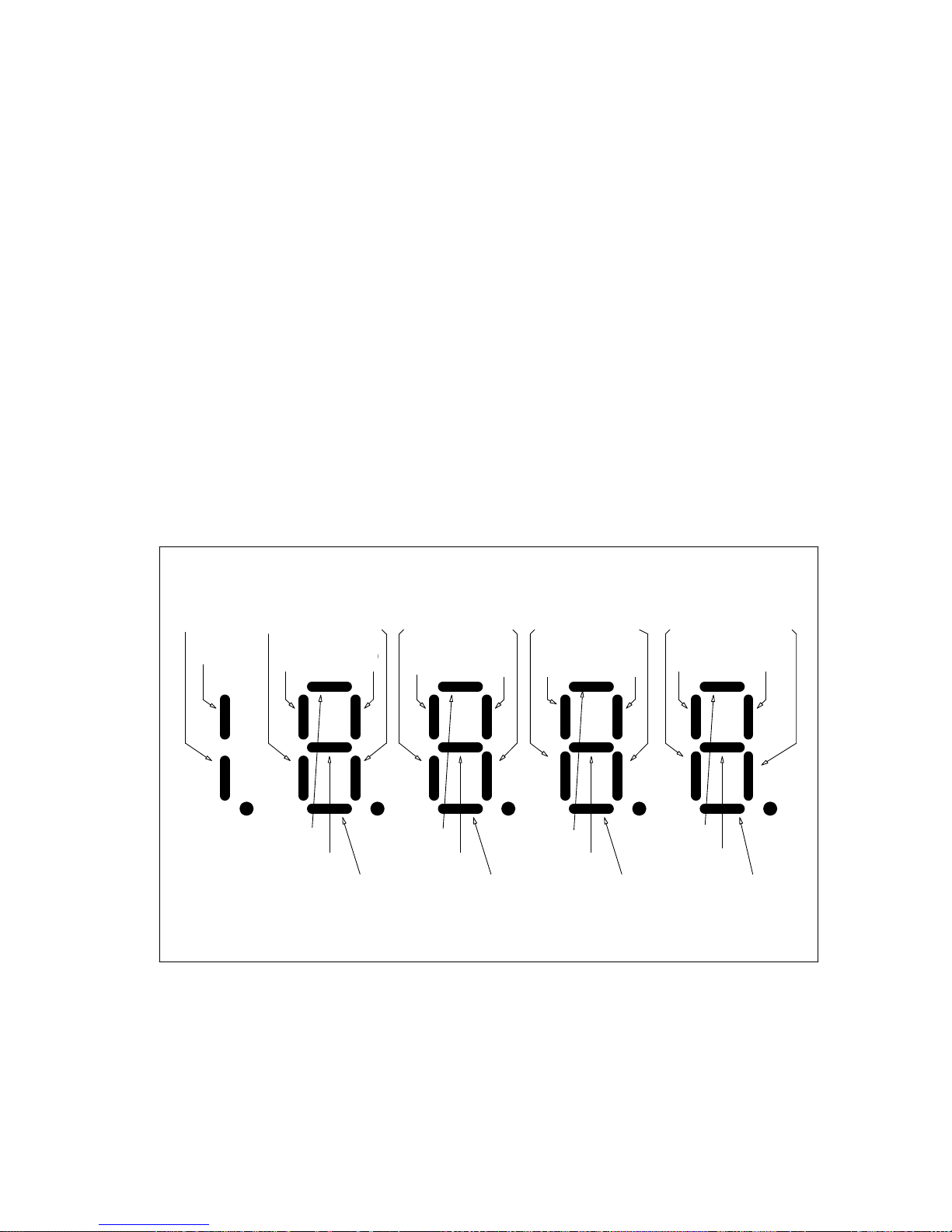
Input – Output Signal Verification
)
Input – Output Signal Verification
The Control Display Unit (CDU) function #981 may be used to directly read and track the status of
logic input and output signals at DSD 412 drive terminals. This is an easy way to verify the integrity of
input and output logic signals to the drive. Refer to specific connection diagrams for your application
to confirm the definition of how each signal is being used. The I/O indicator technique as described
below will work regardless of whether or not the particular terminals and signals are used by internal
software logic or actually wired into your application. Function #981 does not work with the Portable
Control display Unit.
Here’s how to use this valuable troubleshooting tool:
1. Press the Up ▼ or Down ▲ keys and go to F#981.
2. Press the DATA FCTN KEY. The green light should turn ON to indicate that data is being
displayed.
3. Segments on the local Control Display Unit will light up to indicate active input and output logic
actions. Vertical segments represent input signals and horizontal segments represent output signals
as identified below. For more information, see appropriate Figure depending on whether the drive is
being run serially or analog.
S1
TB1(53)
TB1(53)
LPR AUX
TB1(7)
TB1(7)
S2
TB1(12)
TB1(12)
FAULT
RESET
TB1(49)
TB1(49)
K1
TB1(40,41,42)
TB1(40,41,42)
K5
TB1(79)
TB1(79)
I N P U T L O G I C D A T A B I T S
S3
TB1(54)
TB1(54)
RUN OR
RUN UP
TB1(8) TB1(50) TB1(9)
TB1(8)
E-STOP
TB3(6)
DOWN OR
RUN DWN
TB1(50
K2
TB1(38-39)
TB1(38,39)
K6
TB1(83)
TB1(83)
THRMST
TB3(8)
DRIVE
ENABLE
TB1(9)
N-A N-A N-AN-A
N-A N-A N-A N-A
RAMP 2
SEL
TB1(51) TB1(10) TB1(11)
TB1(51)
K3
TB1(36-37)
TB1(36,37)
K7
TB1(84)
TB1(84)
O U T P U T L O G I C D A T A B I T S
RAMP 1
SEL
TB1(10)
S4
TB1(52)
TB1(52)
K4
TB1(78)
TB1(78)
S0
TB1(11)
LPR
TB3(5)
Figure 23: I/O Analog Monitor Function
89
Page 92
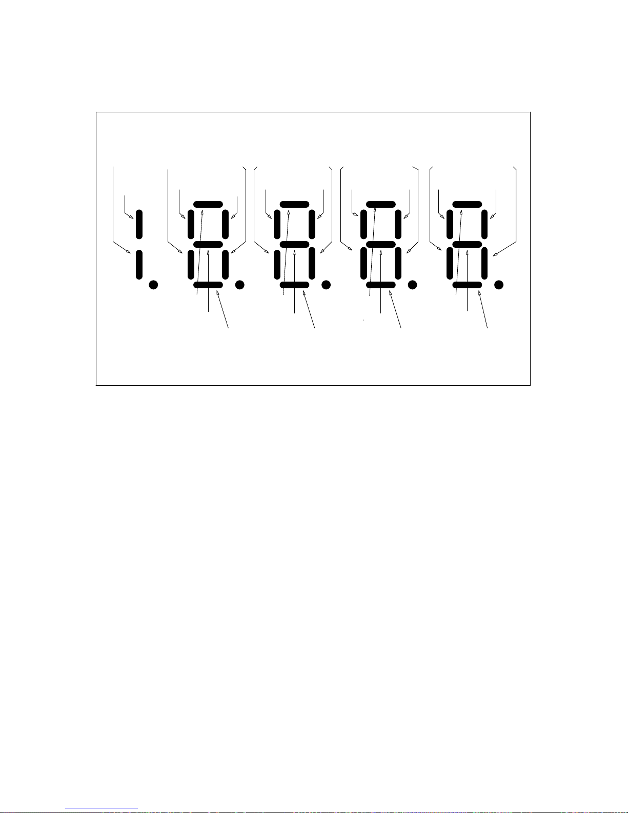
Input – Output Signal Verification
TB1(53)
TB1(12)
LPR AUX
TB1(7)
TB1(7)
TB1(49)
K1
TB1(40,41,42)
TB1(40,41,42)
K5
TB1(79)
TB1(79)
I N P U T L O G I C D A T A B I T S
TB1(54)
RUN
TB1(8) TB1(50) TB1(9)
TB1(8)
K2
TB1(38-39)
TB1(38,39)
SERIAL GAIN
SWITCH
O U T P U T L O G I C D A T A B I T S
E-STOP
TB3(6)
K6
TB1(83)
TB1(83)
THRMST
TB3(8)
SERIAL
N-A N-A N-AN-A
RUN UP
SERIAL
N-A N-A N-A N-A
RUN
TB1(51) TB1(10) TB1(11)
K3
TB1(36-37)
TB1(36,37)
SERIAL
FAULT
RESET
K7
TB1(84)
TB1(84)
SERIAL
RUN DOWN
SERIAL
PRE TORQUE
TB1(52)
K4
TB1(78)
TB1(78)
ENABLE
LPR
TB3(5)
FULL FIELD
SERIAL
FIELD
Figure 24: I/O Serial Monitor Function
90
Page 93

Maintenance
Maintenance
Preventive Maintenance
WARNING
HAZARDOUS VOLTAGES MAY EXIST IN
THE DRIVE CIRCUITS EVEN WITH DRIVE
CIRCUIT BREAKER IN OFF POSITION.
NEVER ATTEMPT PREVENTIVE
MAINTENANCE UNLESS INCOMING
THREE-PHASE AND CONTROL POWER IS
DISCONNECTED AND LOCKED OUT.
Preventive maintenance is primarily a matter of
routine inspection and cleaning. The rectifier
bridge heat sinks should be kept clean by
brushing while using a vacuum cleaner.
Excess dust and dirt accumulation on the heat
sinks can cause overheating of the SCRs.
Periodically check all electrical connections;
tighten as required.
Repair and Replacement Procedures
Replacement parts are listed on page 109.
Either the common name or reference
designator of a particular part may be used to
locate the item in the Recommended Spare
Parts Table to find a replacement part number.
Be sure to use the proper table corresponding
to the ampere rating on the drive nameplate.
Printed Circuit Boards
IMPORTANT
When replacing any printed circuit board
(PCB) or any integrated circuit (IC) in the DSD
drive, proper Electro-static Discharge (ESD)
procedure MUST be followed.
Repair of printed circuit boards requires
special techniques and test equipment. For
this reason, field repair is not authorized,
and replacement of a suspect board is
recommended.
Periodically check air filters on enclosure
doors, if applicable; clean if dirty, replace as
necessary.
Periodically clean the cooling fans to prevent
dirt buildup. At the same time, check that the
impellers are free and not binding in the
housing. Each fan motor is permanently
lubricated; the fan should be replaced if the
shaft does not spin freely.
If/When drive faults occur, follow those aids
based on the observed Error/Fault code. In
some instances, the fault tracing required to
determine the necessary repairs is too
extensive to list in detail in this manual; for
those faults, it is recommended that Magnetek
be called for assistance.
Some of the probable causes in Table 17:
Fault Code Descriptions mention problems at
connectors, all of which are on the Drive
Control PCB. Table 19: Connector Definitions
describes the basic function of each connector,
and Figure 25: Connector and E-prom
Locations on the board.
Defective or questionable printed circuit boards
should be returned to MagneTek, for repair
and test. The printed circuit board should be
ESD protected, then individually protected with
an inch thickness of soft wrapping material
before it is packed in a suitable carton.
MagneTek assumes no responsibility for
printed circuit boards returned without proper
return tags and forms. Contact your Magnetek
sales representative for proper return tags and
forms.
91
Page 94
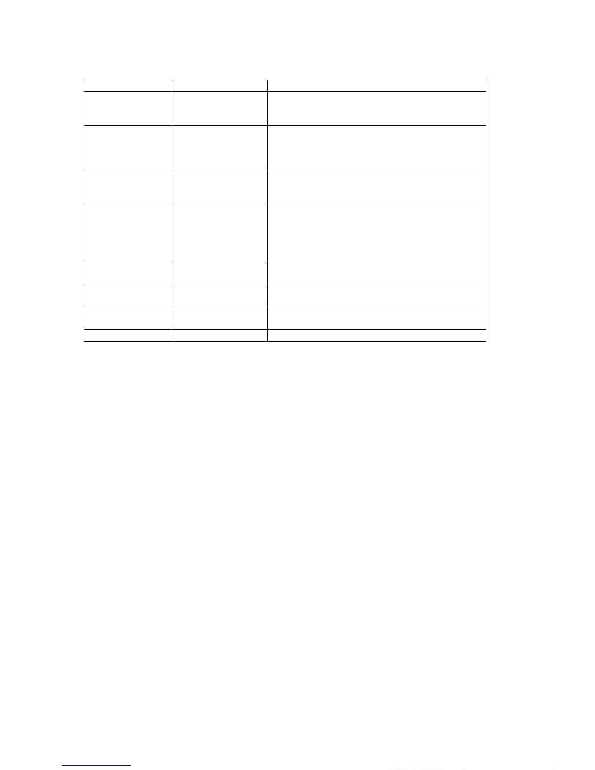
Maintenance
CONNECTOR TYPE FUNCTION
Provides interface to connections for external
J1 DB-9
J2
J11 20-Pin Header
J13 10-Pin Header
J14 40-Pin Header
J31 10-Pin Header
J32 4-Pin Header
J33 10-Pin Header Connects J13 to Signal Interface PCB, A3.
RJ-12 Phone jack
plug 6-pin
RS422 serial link controls. J1 and J2 are
mutually exclusive.
Provides interface connection for external
RS232 devices. The optional PCDU plugs into
this connector. J1 and J2 are mutually
exclusive.
Provides power supply voltages and control
signals to the Drive Control PCB from the DSD
412 Power Supply PCB.
Provides power supply and board sensing
connections to the DSD401 Signal Interface
PCB, A3. [This cable is the same as that used
to connect the standard DSD 412 field Interface
PCB.]
Provides control and feedback signal
connections to the Armature Interface PCB
Connects TB1 logic signals to Signal Interface
PCB A3.
Connects analog output signals from TB1 to
Signal Interface PCB A3.
Table 19: Connector Definitions
92
Page 95
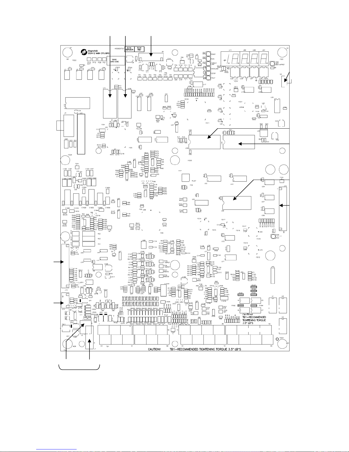
U13 U14 J11
Maintenance
S3
NV RAM
PROTECT
SWITCH
U39
U40
U50
J14
J13
J2 J1
ONLY ONE
PRESENT AT
J12
Figure 25: Connector and E-prom Locations
93
Page 96
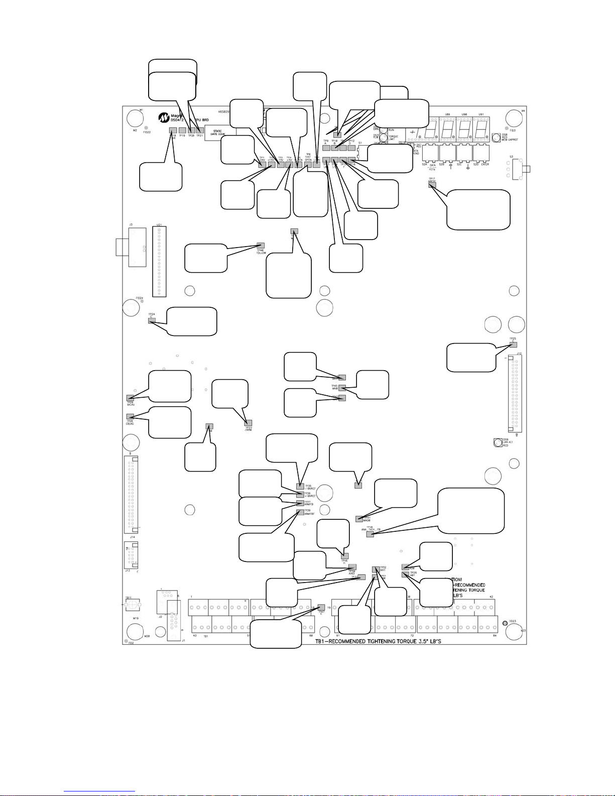
Maintenance
A
p
A
A
A
A
A
A
A
A
A
A
TP19-21
N
TP40
TP40
Follow
Follow
TP40
Follow
TP29
BALag
TP28
CBLag
TP40
Follow
TP24
Common
TP30
V
TP3
-15V
TP1
+24V
TP2
+15V
TP22
/ARM
TP4
+5V
TP36
+10VR
TP37
RMFB
TP39
RMIFBF
TP47
Common
TP7
Low
TP5
en
SO
TP6
Thst
Open
TP23
WDOG
DIS
TP43
MAI2
TP42
MAI1
TP35
-10VREF
TP34
TP33
IN2
IN3
TP8
Common
TP13
LAN
TP44
MAO1
TP46
FI
TP14
E/O
TP31
IN0
TP1
TP1
TP1
+24V
+24V
+24V
TP9-12
TP16
E Scan
TP15
F Scan
TP45
MAI0
TP41
MAO0
TP32
-D Scan
TP17
ABCDE
Scan Time
TP25
Common
TP38
ANA_
TACH_FB
TP27
O0
TP26
O1
IN1
Figure 26: Test Point Locations
94
Page 97
Maintenance
TEST POINT FUNCTION DESCRIPTION
TP1 +24V SUPPLY +24V SUPPLY
TP2 +15V SUPPLY +15V SUPPLY
TP3 -15V SUPPLY -15V SUPPLY
TP4 +5V SUPPLY +5V SUPPLY
TP5 EMERGENCY STOP OPEN HI = EMERGENCY STOP IS OPEN
TP6 THERMOSTAT OPEN HI = THERMOSTAT IS OPEN
TP7 LOW PWR SUPPLY WARN HI = LOW 115VAC TO PWR SUPPLY
TP8 COMMON COMMON
TP24 COMMON COMMON
TP25 COMMON COMMON
TP47 COMMON COMMON
TP9 A SCAN TIME HI = DCU A SCAN IS RUNNING
TP10 B SCAN TIME HI = DCU B SCAN IS RUNNING
TP11 C SCAN TIME HI = DCU C SCAN IS RUNNING
TP12 D SCAN TIME HI = DCU D SCAN IS RUNNING
TP13 LAN Chip select for Lan mode; High = Active
TP14 E/O EVEN/ODD Address Select; High = +5V
TP15 F SCAN TIME HI = DCU F SCAN IS RUNNING
TP16 E SCAN TIME HI = DCU E SCAN IS RUNNING
TP17 ABCDE SCAN TIME HI = DCR ABCDE or F SCAN IS RUNNING
TP18 BUS DIR N/A
TP19 RESERVED FOR TESTING N/A
TP20 RESERVED FOR TESTING N/A
TP21 RESERVED FOR TESTING N/A
TP22 ARMATURE DISABLE Logic 1 when Forward or Reverse Bridge is firing.
Jumper to COMMON to disable Bridge.
TP23 WATCHDOG DISABLE Logic 0 during POWER-UP CPU RESET;
Otherwise Logic 1.
TP26 ANALOG OUTPUT, TB1-26 Analog Output Signal on TB1-26
TP27 ANALOG OUTPUT, TB1-27 Analog Output Signal on TB1-25
TP28 CB LAG C-B PHASE SIGNAL
TP29 BA LAG B-A PHASE SIGNAL
TP30 ARMATURE VOLTAGE SCALING = 100/1 (100VDC ON ARMATURE =
1VDC ON TP30)
TP31 ANALOG INPUT ANALOG INPUT SIGNAL ON TB1-58
TP32 ANALOG INPUT ANALOG INPUT SIGNAL ON TB1-59
TP33 ANALOG INPUT ANALOG INPUT SIGNAL ON TB1-60
TP34 ANALOG INPUT ANALOG INPUT SIGNAL ON TB1-61
95
Page 98
Maintenance
TEST POINT FUNCTION DESCRIPTION
TP35 -10V REFERENCE OUTPUT -10V REF OUTPUT AT TB1-29
TP36 +10V REFERENCE OUTPUT +10V REF OUTPUT AT TB1-28
TP37 ARMATURE CURRENT
FEEDBACK
TP38 ANALOG TACH FEEDBACK ANALOG TACH SIGNAL (when used)
TP39 ARMATURE CURRENT
FEEDBACK
TP40 DIFF ANALOG INPUT +/- 10V DIFF INPUT ON TB1-63, 68 OR +/-600MV
TP41 ANALOG OUTPUT #0 Analog Output to TB1-45
TP42 DIFF ANALOG INPUT, +/-
10V, OR +/- 0-600MV
TP43 DIFF ANALOG INPUT +/-
10V
TP44 ANALOG OUTPUT #1 ANALOG OUTPUT to TB1-46
TP45 DIFF ANALOG INPUT, +/-
600MV
3V @ 1 PU (Use Shielded Probe to avoid noise
pick-up. Noise will cause erratic Drive operation)
See TP39.
Filtered Armature Current Feedback Signal.
Average of Armature Current.
DIFF INPUT ON TB1-64, 67
DIFF INPUT, +/-10V TO TB1-71, 76 OR +/- 0600MV DIFF INPUT TO TB1-72, 75
DIFF INPUT, +/- 10V TO TB1-30, 31
+/- 600MV TO TB1-34, 35
6.9A Term, TP46 = [email protected]
16.0A Term, TP46 = [email protected]
40.0A Term, TP46 = [email protected]
Table 20: Test Point Definitions
96
Page 99
Drive Control PCB Replacement
1. Release the front cover of the drive by
pulling out the four corner fasteners,
approximately 1/4 inch, until they snap;
then remove the cover.
2. Mark each cable and wire to ensure proper
reconnection; before disconnecting them.
3. Disconnect all cables and wires from the
Drive Control PCB. Remove nine screws
holding the Drive Control PCB to the swing
out door chassis from the front, and
remove the Drive Control PCB from the
power cube.
4. If there is an optional circuit board
attached to the back of the Drive Control
PCB, disconnect the Local I/O cable from
J12 on the Drive Control PCB. Then
remove the mounting screws which secure
the Local I/O PCB to the back of the Drive
Control PCB. Re-attach the same Local
I/O PCB to the replacement Drive Control
PCB using the same hardware in reverse
order. Re-attach the J12 cable.
5. Mount the new Drive Control PCB into the
power cube by reversing procedure in
steps 1 through 3. Be sure to re-use the
small diameter flat washers under the
screw heads on the Drive Control PCB to
maintain proper electrical clearances.
6. Remove integrated circuits (ICs) U13, U14,
U39, U40 as appropriate, from the
defective Drive Control PCB. Install into
the same positions on the new board.
Ensure that polarity notch on IC is aligned
with the silkscreen notch on the board.
Each IC is marked with the proper “U”
number in the bottom left hand corner of its
label.
7. Perform Start-Up Procedure.
IC Replacement
IMPORTANT
When replacing any printed circuit board
(PCB) or any integrated circuit (IC) in the DSD
drive, proper Electro-static Discharge (ESD)
procedure MUST be followed.
EPROM Replacement
To replace an EPROM (U13, U14, U39, U40),
first check that the new device has the same
“U” number on its label as the defective device.
Remove the existing device and install the
Maintenance
replacement in the same position. Then
perform the Start-Up Procedure in Drive Start .
NVRAM Replacement
To replace an NVRAM device (U56), remove
the defective device and install the
replacement in the same position. Then
perform the Start-Up Procedure. If you have
kept a record of the parameter settings you
should be able to re-load all parameter values,
save the data and go. If you do not have a
record of the working drive parameter settings,
you must re-enter and re-tune all parameters
by repeating all drive adjustment procedures.
Testing and Replacement of Power
Components.
Fuse Replacement
Whenever attaching a fuse, wire or bus bar to
another component to achieve an electrical
connection, always apply a thin coating of
electrically conductive joint compound to all
contacting surfaces. Magnetek recommends
using Joint-Al-Z compound for all bolted
electrical power connections.
Diagnosis of fuses — The input AC fuses are
checked when power is initially applied during
the Start-Up sequence of the drive, and again
when a PCU DIAGNOSTICS #998 is
performed. The output DC fuse is checked
only when a PCU DIAGNOSTICS #998 is
performed. When running, blown fuses may
cause an F910 or F404. With input power
disconnected, the fuses may be checked with
an ohmmeter while still in place in the circuit.
Replace any fuse that indicates a resistance
reading of more than a fraction of an ohm. Re
check that the fuse is indeed open/blown when
removed from the circuit. Be aware that other
circuitry may cause a low resistance reading to
appear across a blown fuse. If there are
doubts about the fuse being good or bad,
remove connections to at least one end before
measurement. For maximum assurance to
prevent callbacks, Magnetek recommends
replacing all three AC line fuses even when
only one or two are blown.
If the drive blows AC input fuses, check for
shorted SCRs before power is re-applied.
While the input fuses are removed for
replacement, measure circuit resistance from
each AC line to AC line on the SCR power
bridge side of the fuse connections, and from
each AC line to the DC output busses. If
97
Page 100

Maintenance
resistance readings are less than 100 K-ohms,
suspect shorted or badly damaged SCRs.
Replace those faulty parts before attempting to
power up again with fresh fuses.
There is a small fuse inside the Drive Power
Supply, A4. This fuse may blow if 115 Vac
control power has surged above 135 volts. If
there is voltage at A4TB3-1 & A4TB3-7, but
the power supply does not appear to work, this
fuse may be checked by removing the power
supply cover. A blown power supply fuse does
not necessarily mean that the power supply is
faulty as the fuse also protects a transient
surge suppressor contained within. External
surges on the 115VAC control voltage power
source can cause this fuse to blow.
Testing and Replacement of Power
Semiconductors and Snubber
Components.
If SCRs are suspect, test for short circuits
before disassembly to help locate the problem.
Refer to specific instructions in this manual for
the drive ampere size. Perform the suggested
ohmmeter tests to verify that there are no
direct short circuits. Then perform the PCU
DIAGNOSTICS #998. These tests will perform
shorted and open SCR tests to help indicate
which SCRs need replacement.
Several different DSD 412 power circuit
configurations exist in order to handle rated
currents from 25 to 1350 amperes. Refer to
the proper sub-section in this manual
according to rated drive current as listed on the
nameplate for specific service information for
the individual power conversion units.
Testing and Replacement of the Motor
Field Control Module and PCB
Components of the DSD 412 for control of
motor field consist of the A3 PCB and
associated SCR/Rectifier module Q7 located
under the PCB. Input power is single phase
voltage supplied to A3TB1 terminals AC1 and
AC2. Motor field current DC amperes are
measured by a current transducer (CT) located
on the PCB. Connecting the F1 (+) field wire
to TB4 selects the full scale current range.
Switch A3S1 is used to tell the microprocessor
what ‘tap’ is being used.
nominal value. This voltage is phase
sensitive and must be derived as shown in
drawing of Figure 2.1a.
2. Verify motor field current flow calibration
by reading motor current with a separate
clamp-on DC ammeter. Compare the
reading with that of #612. If these two
readings do not correspond, verify that
A3S1 is correctly set and that the F1(+)
lead is connected to the right tap.
3. Read and verify VDC output to the motor
field between A3TB4 F2(-) and
A3TB4F1(+).
4. Turn all power off. Temporarily remove
one power feed wire from A3TB1-AC1 and
test the SCR/Rectifier module for shorts
with an ohmmeter between each screw
connection to the PCB. If short circuits
exist, replace the module AND the PCB.
Field Control A3 PCB Replacement
1. Label and disconnect all power wires to
terminals on the PCB. Disconnect ribbon
connector J13.
2. Disconnect wires G1 & G2 from the
SCR/Rectifier module. Remove 4 screws
holding PCB to SCR/Rectifier module.
Remove PCB at each plastic post by
gently pulling straight out.
3. Reverse the above procedure to
reassemble. Torque the 4 SCR/Rectifier
module screws to 18 in-lbs.
Field Control SCR/Rectifier Replacement
1. Remove the A3 PCB according to the
above.
2. Remove the 2 cap screws securing the
module to the heatsink and remove the
damaged module.
3. Wipe the mounting surface clean. Use a
new thermal mounting pad or a thin
coating of thermal grease on the bottom of
the replacement module. Orient the
module with AC1 & AC2 terminals toward
the right side of the unit. Use cupped
washers under the mounting screw heads.
Tighten mounting hardware to 18 inch-lbs.
4. Reassemble the A3 PCB and all electrical
connections.
If the desired motor field current cannot be
obtained:
1. Verify that the proper AC voltage is
available at terminals A3TB1-AC1 &
A3TB1AC2. Verify that #55 is set to this
98
 Loading...