

Page 1
Datalogger
DataLogger and DataPulse Software
Febuary 2005
© Copyright 2005 Magnetek
™
Instruction Manual
Page 2

©2005 ELECTROMOTIVE SYSTEMS
All rights reserved. This notice applies to all copyrighted materials included with this product,
including, but not limited to, this manual and software embodied within the product. This manual is
intended for the sole use of the persons to whom it was provided, and any unauthorized distribution
of the manual or dispersal of its contents is strictly forbidden. This manual may not be reproduced in
whole or in part by any means whatsoever without the expressed written permission of Magnetek’s
Electromotive Systems.
DANGER, WARNING, CAUTION, and NOTE
Statements
DANGER, WARNING, CAUTION, and Note statements maybe used in this manual to
emphasize important and critical information. You must read these statements to help ensure
safety and to prevent product damage.
NOTE: A NOTE statement is used to notify installation, operation, programming, or
maintenance information that is important, but not hazard-related.
Impulse DataLogger Series 3 Instruction Manual
2/1/05
1 of 16
Page 3
Section 1: Overview
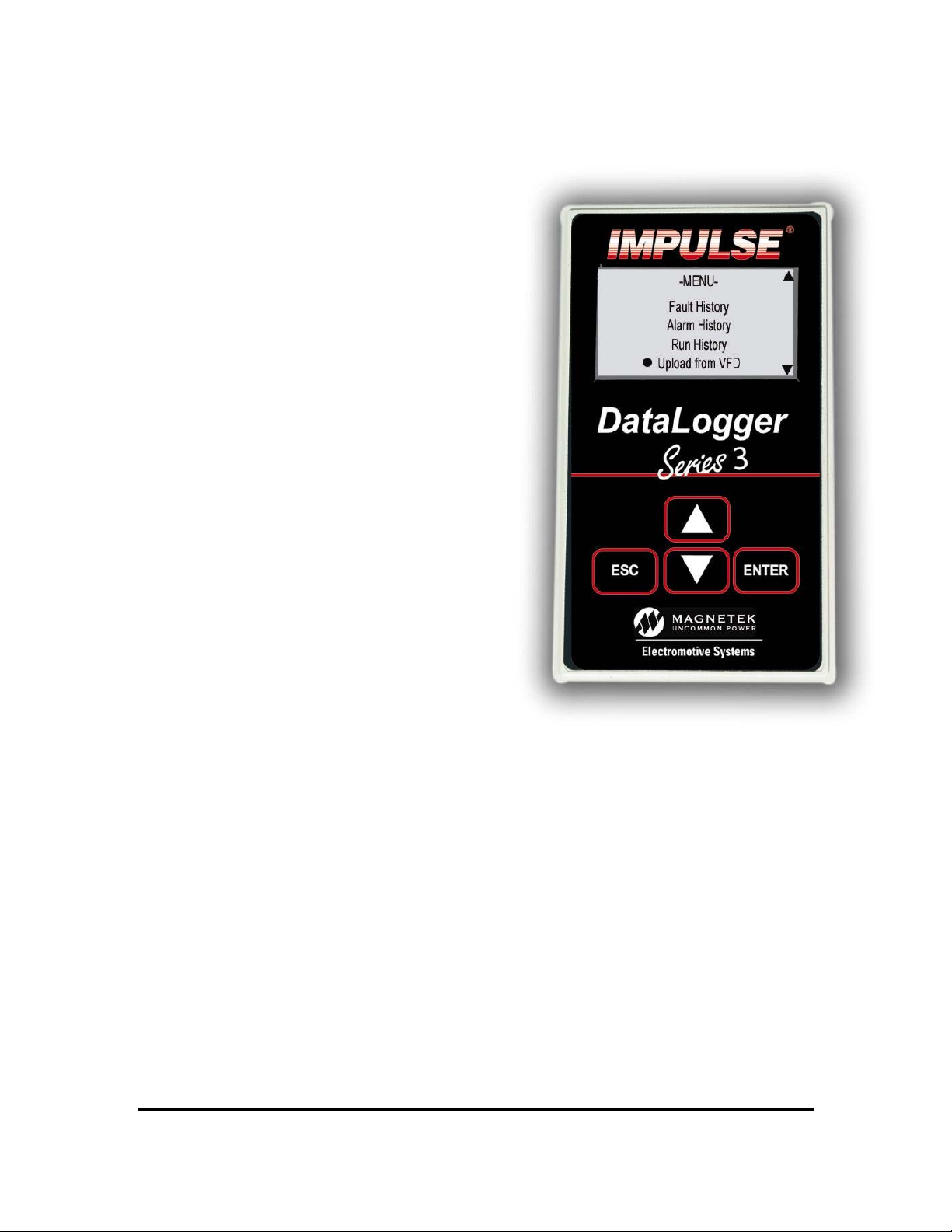
The DataLogger Series 3 was
designed to simplify troubleshooting
and provide for detailed operational
histories that are necessary for
genuine preventive maintenance.
The DataLogger is a nonvolatile
solid state (flash memory) recording
device that allows the operator to
easily and logically access the
Run, Alarm & Fault histories
of the IMPULSE•G+/VG+ Series 2
and IMPULSE•G+/VG+ Series 3
drives. It will also store 5 parameter
sets. The DataLogger was
designed to be a fit and form
replacement to the Series 3 keypad.
An additional cable is required
for use with Series 2 drives.
The DataLogger System consists of
three (3) components:
the DataLogger, the USB cable
for PC communication and
DataPulse™ Series 3 software.
The DataLogger was designed to include sufficient memory to log the last 1400
Run Events, the last 200 Alarm Events and the last 200 Fault Events. In addition
to the Alarm and Fault history, a Trace function is provided for viewing drive data
that lead to the Alarm/ Fault condition. The user-friendly DataLogger can be
effectively applied by those with little or no knowledge of inverters. All data
acquisition is automatic, and data viewing and analysis is available via the LCD
display or by uploading and viewing on your PC. The logger is powered by the
inverters 5 VDC internal supply when logging or by the USB when connected to
the PC. The internal clock is powered by a replaceable Lithium coin type battery.
Impulse DataLogger Series 3 Instruction Manual
2/1/05
2 of 16
Page 4

How data logging works:
The DataLogger is a device which polls the Drive via the RS232 CN1 port.
Once connected, the logger will read the Inverter Status and U1
parameters. From the Inverter Status, the logger can detect when the drive
is running or when a fault or alarm occurs. Note: the logger must be in
Monitor mode to log any data.
When a run occurs:
When the logger detects a run, it increments the run counter and begins to
take averages and store peak values of the U1 parameters being read. It
also records how long the run remains active. When the run is ended, this
information is written to memory for storage. If it ended due to a fault or
alarm the reference to that fault/alarm is also associated to the run.
When a fault occurs:
When the logger detects a fault, it reads an additional set of registers from
the drive, named the fault content registers. These registers identify which
fault(s) are present. Once read, each register is checked to filter out specific
faults, such as DC Bus undervoltage, which would be logged every time the
drive power is cycled, if not filtered. Once the check is done, if a valid fault
still exists, the U2 parameters are read from the drive. Once read, the fault
data is written to memory for storage. In addition, the U1 parameters are
written to memory as trace data. This gives the past five scans of data just
before the fault occurs, in addition to the drive-stored fault data. If a run
event was present when the fault occurred, the reference to that run is also
saved with the fault data. If the logger is connected and monitoring, the
ENTER button will reset the fault.
When an alarm occurs:
When the logger detects an alarm, it reads an additional set of registers
from the drive, named the alarm content registers. These registers identify
which alarm(s) are present. Once read, each register is checked to filter out
specific alarms, such as DC Bus undervoltage, which would be logged
every time the drive power is cycled, if not filtered. Once the check is done,
if any alarms still exist, the current U1 parameters are saved to memory for
storage. In addition, the U1 parameters are written to memory as trace
data. This gives the past five scans of data leading up to the alarm. If a run
event was present when the alarm occurred, the reference to that run is
also saved with the alarm data.
Impulse DataLogger Series 3 Instruction Manual 2/1/05
3 of 16
Page 5

Logging of Run, Fault, Alarm and Trace Data
All Data collection is automatic, viewing data is per the various screens, and the
roadmap of functions per the diagram on the Menu Navigation on page 6. The
Monitor Mode of the DataLogger permits Real Time monitoring of Inverter activity.
Uploading and downloading parameter data
The drive parameters can be uploaded (stored) into the DataLogger for use at a
later time. This data, after uploading into the DataLogger, can then be used to
easily create duplicate drives during manufacturing or to create a duplicate drive in
the case of inverter failure and/or replacement. The parameter data can also be
viewed and saved to the PC using the DataPulse Series 3 PC software included
with each logger or available as a download at electromotive.com website. A drive
parameter set can be downloaded into a drive of same software version, model,
control method (flux vector, open loop vector or V/F) and motion. Caution should
be taken when downloading parameters into a flux vector drive. An autotune
should be performed even if the motors seemingly are identical to ensure peak
performance.
GETTING CONNECTED
The Datalogger supports all software versions for Series 3 drives and the
following software versions for Series 2 drives: 14906, 14908, 14909, 14911,
Impulse DataLogger Series 3 Instruction Manual 2/1/05
4 of 16
Page 6
14912, 14920, 14940, 14960, 14961, 14962, 14964, 14965, and 14980.
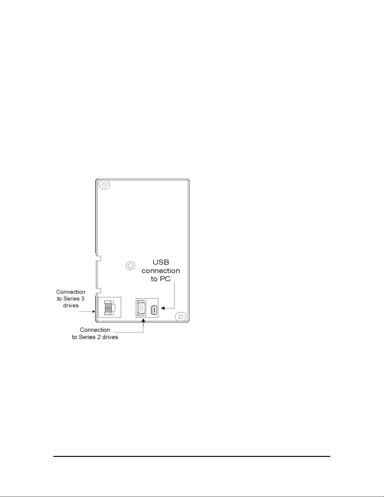
For connection to Series 3 drives, simply replace the keypad with the data logger.
The DataLogger will automatically begin logging after a 2 second boot up.
For connection to a Series 2 drive remove the existing keypad. Use the ribbon
cable, p/n 140-10274 supplied and connect the 12 pin connector end to the Series
2 keypad port. Connect the 8 pin connector end to port on the rear of the
DataLogger.
Note: After a short time without a keyed input the logger displays a screen save
mode. When in the screen save mode, press any of the four keys on the logger to
display the menu.
Impulse DataLogger Series 3 Instruction Manual 2/1/05
5 of 16
Page 7
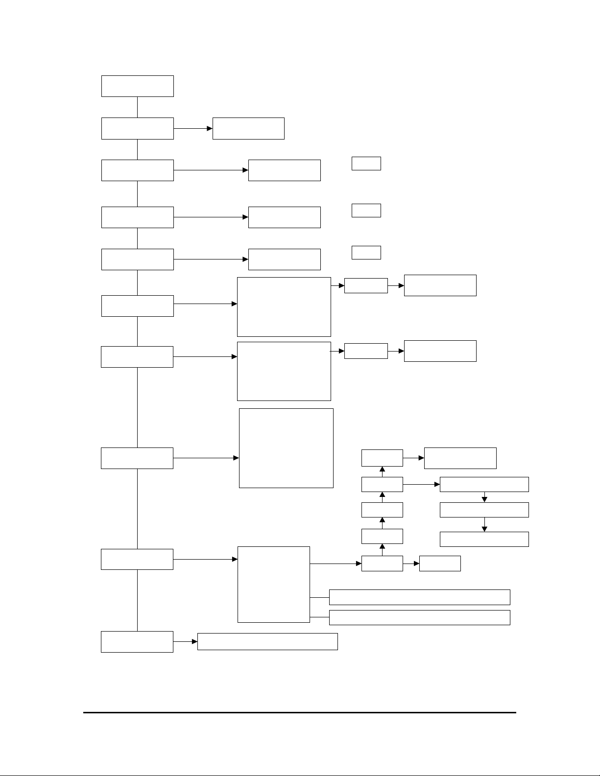
DATALOGGER MENU NAVIGATION
-Main Menu-
Monitor
Fault History
Alarm History
Run History
Upload from
VFD
Download from
VFD
Monitor Mode
Displays last
fault data
Displays last
Alarm data
Displays last
Run data
Drive 1 : 8001, 4011,
12/03/04 4:24 56
Drive 2 : Empty
Drive 3 : Empty
Drive 4 : Empty
Drive 5 : Empty
Drive 1 : 8001, 4011,
12/03/04 4:24 56
Drive 2 : Empty
Drive 3 : Empty
Drive 4 : Empty
Drive 5 : Empty
Datalogging is
automatic in monitor
mode
Enter
Hold and or
to scroll through faults
Enter
Hold and or
to scroll through Alarms
Enter
Hold and or
to scroll through Runs
ENTER
Drive 1 slot has a parameter set in memory with
software 8001, model 4011, uploaded on 12/03/
04 at 4:24 AM
The other 4 slots are empty. Scroll to the desired
memory location and select ENTER to upload.
ENTER
Select a slot that has a parameter
set in memory and select ENTER to
download into VFD.
Uploading....
Downloading....
-Clear Clear Logger Data
Clear Drive 1
Clear Drive 2
Clear Data
Clear Drive 3
Clear Drive 4
Screen
Save Mode
00-Disabled
01-Enabled
Clear Drive 5
Settings
Version
Clear memory
-SETTINGS Initalize
Fault Filters
Alarm Filters
Displays logger software version
Initialize
Time
Date/yr
Language
Selects faults that you do not want to record
Selects alarms that you do not want to record
01-Restore Default Settings
02-Reset Alarm Filters
03-Reset Fault Filters
English
Impulse DataLogger Series 3 Instruction Manual 2/1/05
6 of 16
Page 8
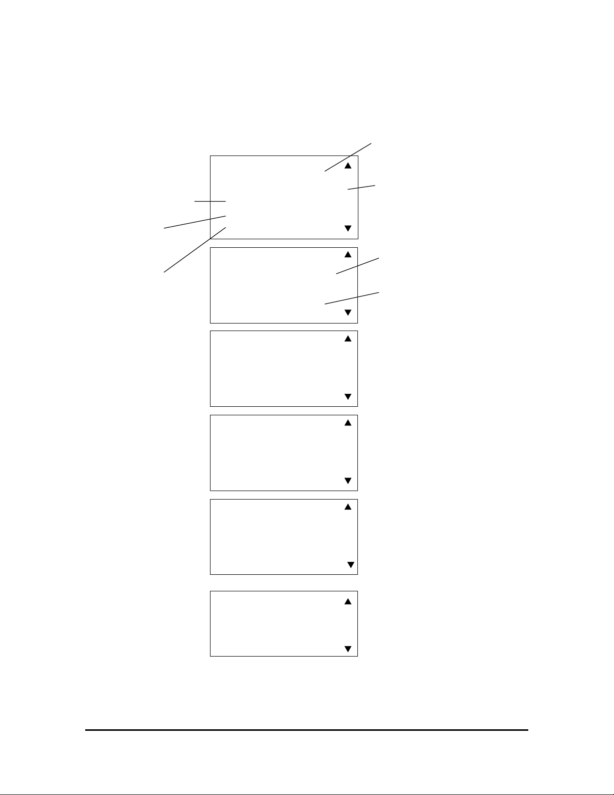
The Monitor Mode provides for Real-Time display of Inverter operation. It also
indicates the total number of Run events, Alarm and Fault events.
Date & Time:
Used to time stamp all
history and trace data.
Run Status:
Indicates Running Forward,
Running Reverse or Stopped.
Last Flt:
Indicates the last fault
recorded w/time and date.
Last Alm:
Indicates the last alarm
recorded w/time and date.
Accum Runs:
Indicates the number of
run commands given.
Accum Faults:
Indicates the number of
faults recorded.
Accum Alarms:
Indicates the number of
Alarms recorded.
- MONITOR MODE -
01/28/04 08:44:13
Run Status: Stopped
Accum Runs: 0001
Accum Faults: 0001
Accum Alarms: 0000
- MONITOR MODE -
01/28/04 08:44:13
Last Flt: DC Bus UV
01/28/04 08:35
Last Alm: UL1
01/29/04 02:37
- MONITOR MODE -
01/28/04 08:44:13
U1-01: 000.00 Hz
U1-02: 000.00 Hz
U1-03: 000.00 A
U1-04: 0000
- MONITOR MODE -
01/28/04 08:44:13
U1-05: 000.00 Hz
U1-06: 000.0 VAC
U1-07: 000 VDC
U1-08: 000.0 Hp
- MONITOR MODE -
01/28/04 08:44:13
U1-09: 000.0 %Torque
U1-10: 00000000
U1-11: 00000000
U1-12: 00000000
- MONITOR MODE -
01/28/04 08:44:13
U1-13: 0000 H
U1-14: 0000
U1-01 = Frequency Reference
U1-02 = Output Frequency
U1-03 = Output Amps
U1-04 = Control Method
U1-05 = Motor speed
U1-06 = Motor Voltage
U1-07 = DC bus voltage
U1-08 = Output Hp
U1-09 = % Torque Output
U1-10 = Input terminal status
U1-11 = Output terminal status
U1-12 = Operation status
U1-13 = Run timer (hours)
U1-14 = Software ID
Impulse DataLogger Series 3 Instruction Manual 2/1/05
7 of 16
Page 9
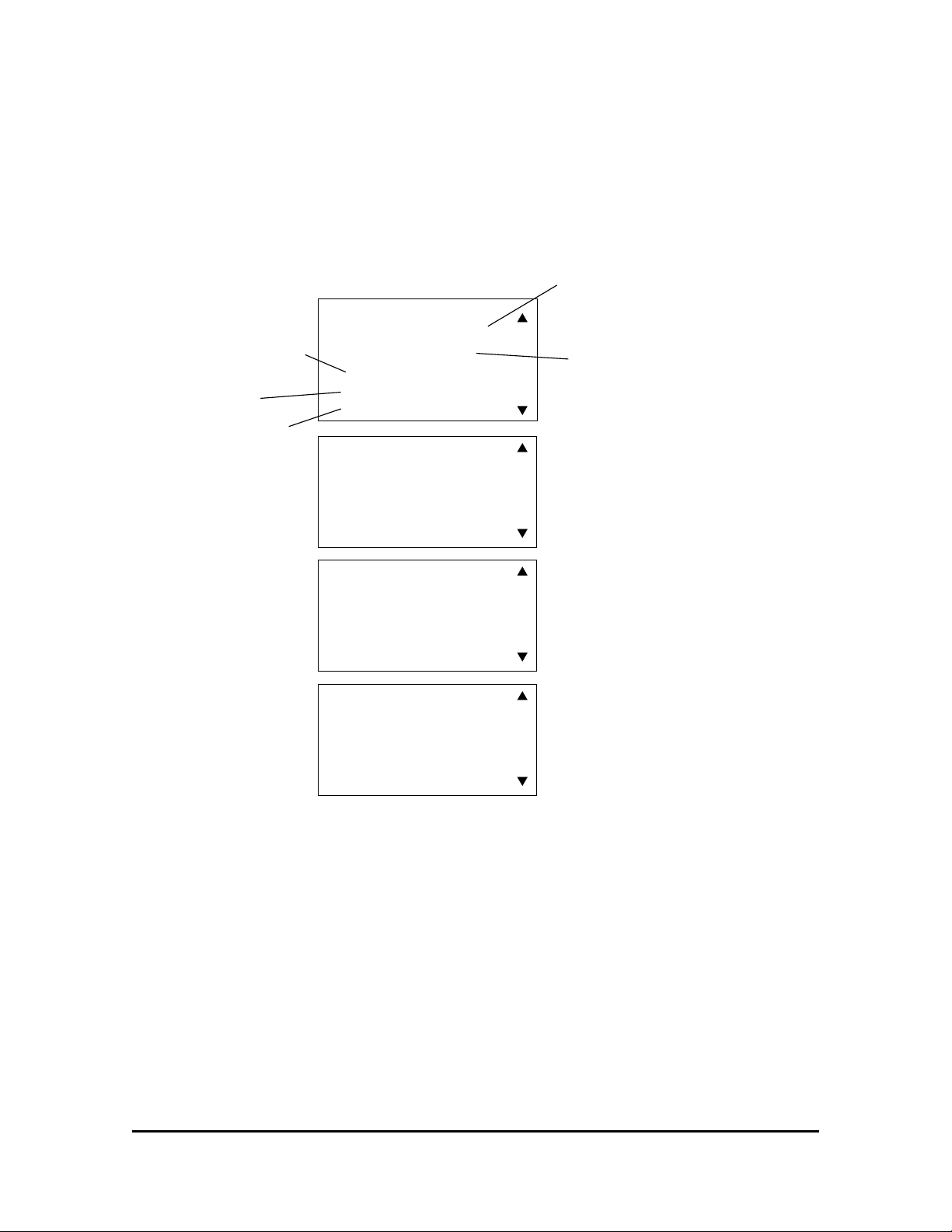
The Fault History provides the data for reviewing recorded faults and information
on each fault occurrence.
Date & Time:
Used to time stamp all
history and trace data.
Fault number
U2-03 = Frequency Reference
U2-04 = Output Frequency
U2-05 = Output Amps
U2-06 = Motor Speed
Run where fault
occured
Fault Description
Date and time of fault
U2-03: 030.00 Hz
U2-04: 017.60 Hz
U2-05: 002.56 A
U2-06: 0000
-FAULT HISTORY -
01/28/04 08:44:13
Flt: 1 OF 6
Run: 5
Ext Fault S7
01/16/04 02:37
- FAULT HISTORY -
01/28/04 08:44:13
U2-07: 000.0 VAC
U2-08: 000.0 VDC
U2-09: 000 KW
U2-10: 000 %
U2-11: 00000000
U2-12: 00000000
U2-13: 00000000
- FAULT HISTORY -
01/28/04 08:44:13
- FAULT HISTORY -
01/28/04 08:44:13
U2-07 = Output Voltage
U2-08 = DC Bus Voltage
U2-09 = Output Kw
U2-10 = Torque Reference
U2-11 = Input terminal status
U2-12 = Output terminal status
U2-13 = Inverter status
FAULT AND ALARM FILTERS
To turn off the recording of any faults or alarms, go to “Settings”, “Fault Filters” or
“Alarm Filters” and press enter. Scroll up or down through the listing of
faults/alarms. If you would like to filter out a fault from being recorded then press
the enter key when the cursor is next to the desired fault. A check mark on the left
hand side will indicate that the fault has been selected to be filtered out. Alarms
would be selected in the same manner.
Impulse DataLogger Series 3 Instruction Manual 2/1/05
8 of 16
Page 10
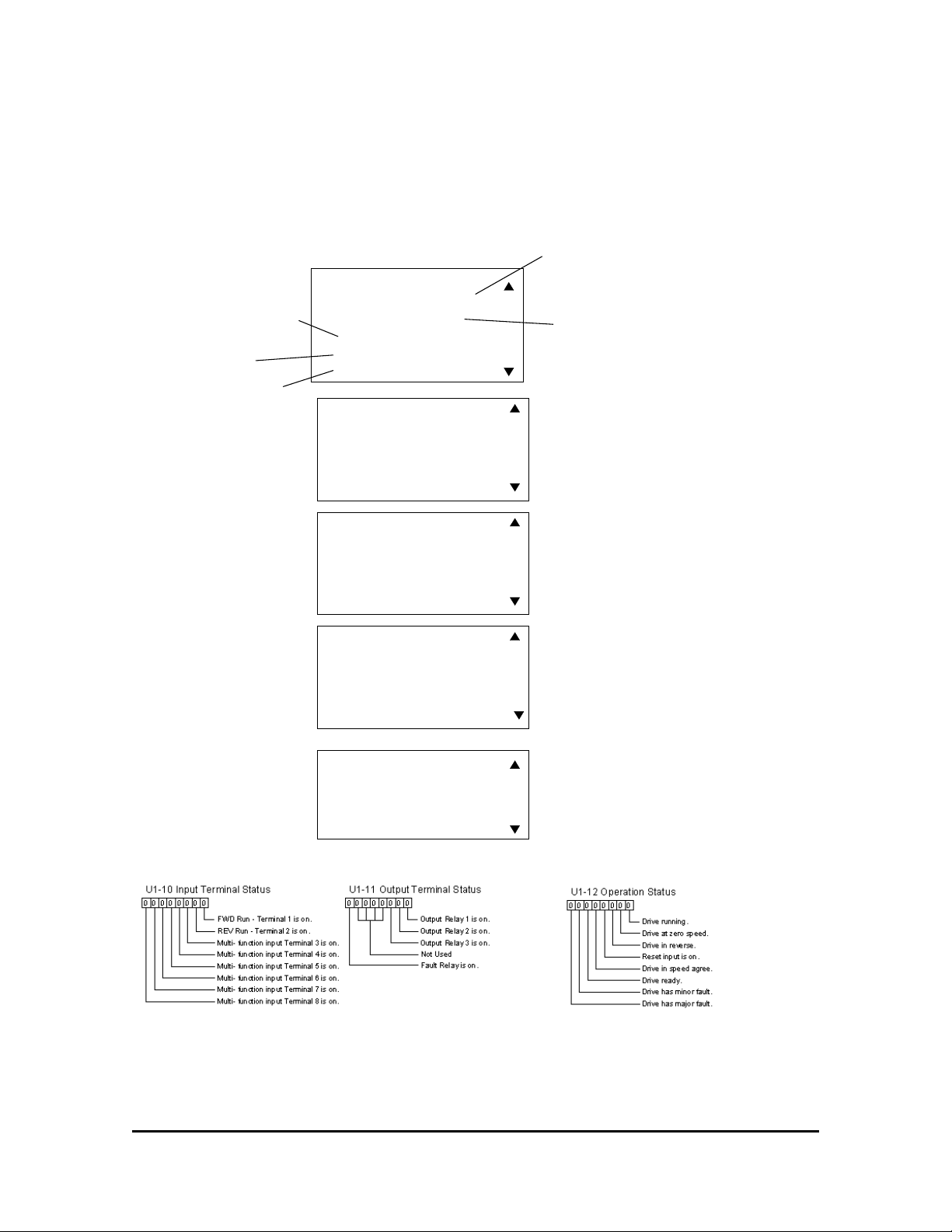
The Alarm History provides the data for reviewing recorded alarms and information
on each alarm occurrence.
Date & Time:
Used to time stamp all
history and trace data.
Alarm number
U1-01 = Frequency Reference
U1-02 = Output Frequency
U1-03 = Output Amps
U1-04 = Control Method
Run where Alarm
occured
Alarm Description
Date and time of Alarm
-ALARM HISTORY -
01/28/04 08:44:13
Alm: 1 OF 26
Run: 1369
Upper Limit1 Err
01/16/04 15:14
-ALARM HISTORY -
01/28/04 08:44:13
U1-01: 000.00 Hz
U1-02: 000.00 Hz
U1-03: 000.00 A
U1-04: 0000
U1-05: 000.00 Hz
U1-06: 000.0 VAC
U1-07: 000 VDC
U1-08: 000.0 Hp
U1-09: 000.0 %Torque
U1-10: 00000000
U1-11: 00000000
U1-12: 00000000
U1-13: 0000 H
-ALARM HISTORY -
01/28/04 08:44:13
-ALARM HISTORY -
01/28/04 08:44:13
-ALARM HISTORY -
01/28/04 08:44:13
U1-05 = Motor speed
U1-06 = Motor Voltage
U1-07 = DC bus voltage
U1-08 = Output Hp
U1-09 = % Torque Output
U1-10 = Input terminal status
U1-11 = Output terminal status
U1-12 = Operation status
U1-13 = Run timer (hours)
Impulse DataLogger Series 3 Instruction Manual 2/1/05
9 of 16
Page 11
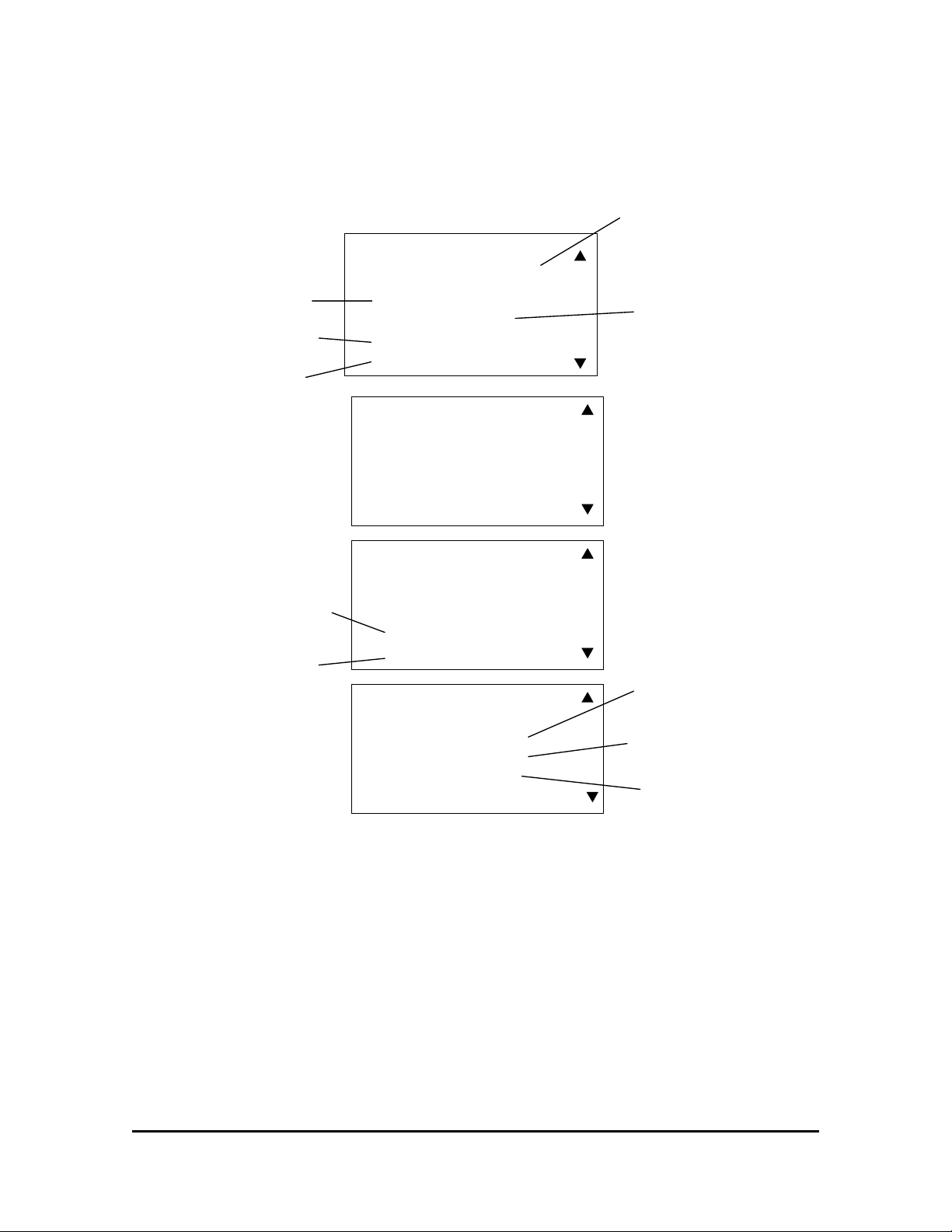
The Run History provides the data for reviewing information on each time the drive
receives a run command or a change in direction.
Date & Time:
Used to time stamp all
history and trace data.
-RUN HISTORY -
01/28/04 08:44:13
Run number
Date and time of run
Duration of run
Fault number if a fault
occured during this run
Fault description
Run: 220 OF 260
Forward
01/16/04 15:14
Duration: 40 Secs
-RUN HISTORY -
01/28/04 08:44:13
Avg Amps: 46.80 A
Peak Amps: 49.90 A
Avg Spd: 7.5 Hz
Peak Spd: 29.4 Hz
-RUN HISTORY -
01/28/04 08:44:13
Avg Bus: 314 VDC
Peak Bus: 320 VDC
Fault#: -- None
-RUN HISTORY -
01/28/04 08:44:13
Alarm Count: 1
Last Alm#: 4
Upper limit2 Err
Direction of motion
Run information
Number of alarms
in this run
Alarm number if a alarm
occured during this run
Alarm description
Impulse DataLogger Series 3 Instruction Manual 2/1/05
10 of 16
Page 12

Introduction to DataPulse Series 3 software
DataPulse is a user friendly, Windows based, DataLogger communication
software that will allow the viewing of logger data in a spreadsheet format.
The DataPulse software functions include:
• Uploading Run, Fault, and Alarm histories and the corresponding trace
data.
• Uploading 5 sets of parameters stored in the DataLogger.
• Displaying and saving the above data.
Computer Requirements
The hardware requirements for DataPulse software:
• IBM-compatible PC with a Pentium 233 MHz or higher processor (Pentium
500 MHz or higher processor recommended)
• 64 MB RAM
• 20 MB hard disk storage
• Microsoft Windows 98se, ME, 2000, or XP
Microsoft Internet Explorer 5.5+ or higher
• USB 1.1 or 2.0 compatible port
Software Installation
The DataPulse software is designed to auto install after CD insertion, if the
installation guide does not display, then in the START menu, choose RUN. . .
and type “D:\setup.exe” where “D” is your CD drive and click “OK” or select
“BROWSE” and select setup.exe and “OK”.
After DataPulse software has finished installing, connect your DataLogger to the
computers USB port. Your PC will require you to install the driver for this “new
hardware”. The driver is located on the DataPulse CD.
Impulse DataLogger Series 3 Instruction Manual 2/1/05
11 of 16
Page 13
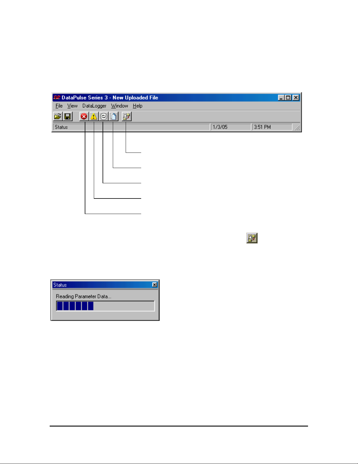
Navigating DATAPULSE Series 3 MENU
Upload data from Datalogger
View parameter data
View Run data
View Alarm data
View Fault data
Uploading data stored in the DataLogger is done through the button located
on the toolbar or by selecting “DataLogger” and “Upload from the DataLogger”
from the Menu. The file must be uploaded before viewing any data. A status bar
will indicate the progress of the upload and the history buttons will be highlighted
after the upload is complete.
Impulse DataLogger Series 3 Instruction Manual 2/1/05
12 of 16
Page 14
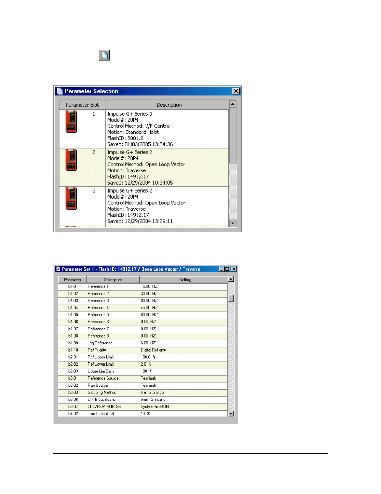
Viewing parameter sets
Selecting the button will display the parameter sets that are stored in the
logger.
Double click on the parameter set of interest and the parameter information is
displayed.
Impulse DataLogger Series 3 Instruction Manual 2/1/05
13 of 16
Page 15
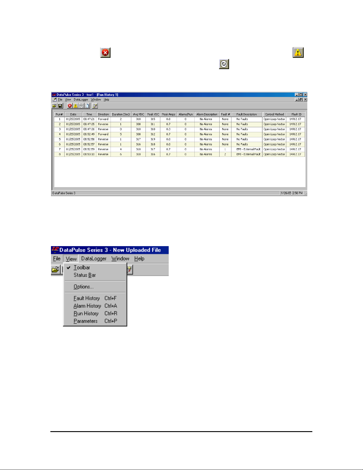
Displaying Drive History Data
Selecting the button will display the fault history window. Selecting the
button will display the alarm history and selecting the button will display the run
history window.
The example below shows a typical display of the history data.
Data columns can be moved by selecting the column header and dragging the
column to a new location. Columns can be deleted by selecting “VIEW” and
“OPTIONS” from the toolbar menu.
Impulse DataLogger Series 3 Instruction Manual 2/1/05
14 of 16
Page 16
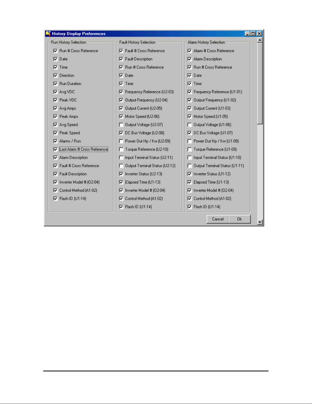
Select the data that you want to display by selecting in the check box.
Impulse DataLogger Series 3 Instruction Manual 2/1/05
15 of 16
Page 17
PRINTING
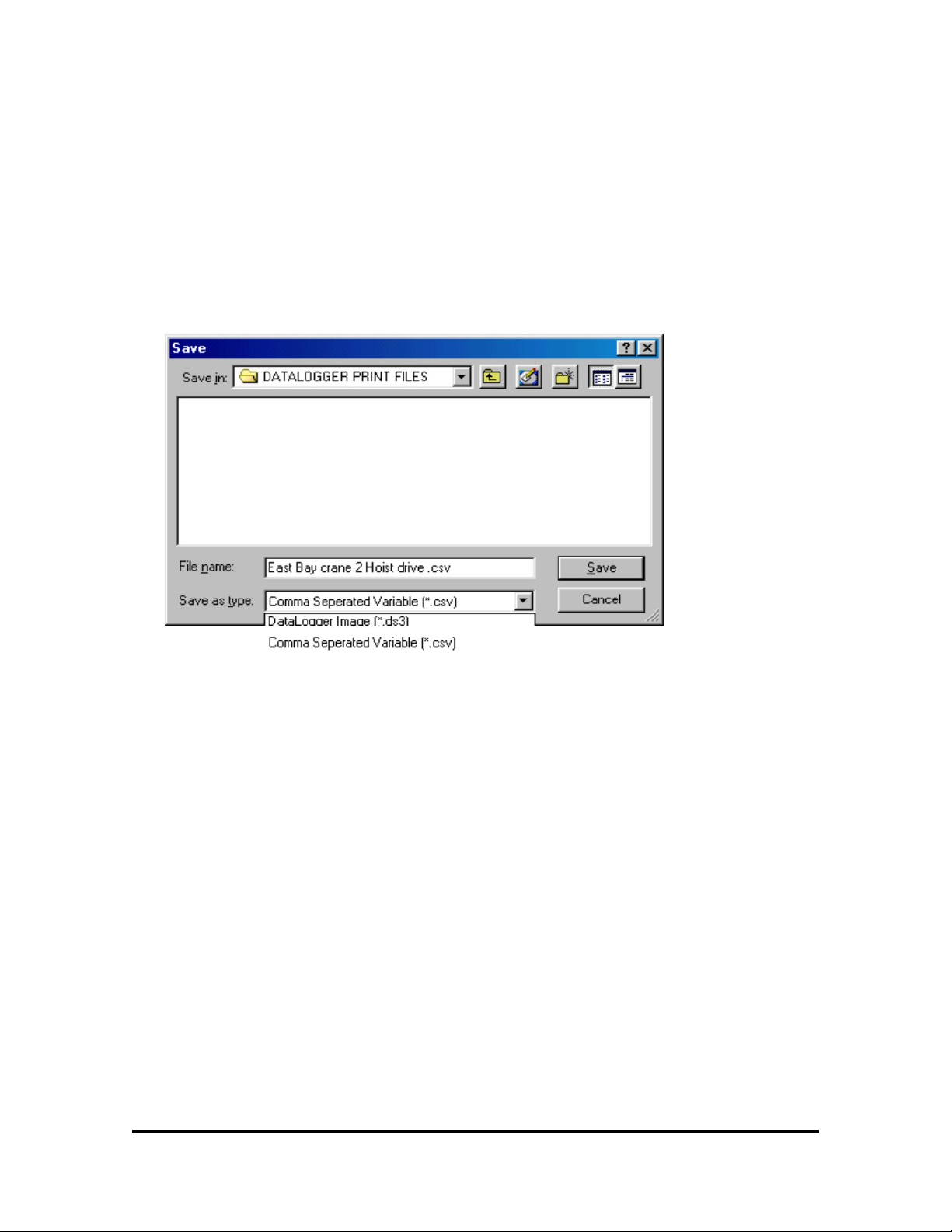
It is best to print only the desired information from the thousands of pieces of data
stored in the logger. To edit and print this information, you would save the file as a
*.CSV file which is a “comma separated variable” file. The file type can be easily
imported into a spreadsheet program for editing and printing.
To save this file as a .CSV file, select “Save as”, “Save as type” and select
“Comma Separated Variable(*.csv)” in the drop down menu. (Be sure to rename
your file.)
Open the *.CSV file in a spreadsheet program such as Microsoft Excel and print
the desired data.
Impulse DataLogger Series 3 Instruction Manual 2/1/05
16 of 16
 Loading...