

Magnetek 188-10130 User Manual

RVS-DX Digital Soft Starter
Instruction Manual
April 1, 2004
Part Number: 188-10130
© Copyright 2004 Magnetek
Power Control Systems

Contents:
Disclaimer of Warranty . . . . . . . . . . . . . . . . . . . . . . . . . . . . . . . . . . . . . . . . . . . . . . . . . . . . . ii-iii
Chapter1: Introduction
Overview . . . . . . . . . . . . . . . . . . . . . . . . . . . . . . . . . . . . . . . . . . . . . . . . . . . . . . . . . . . . . . . . . . 1-3
Starter Selection . . . . . . . . . . . . . . . . . . . . . . . . . . . . . . . . . . . . . . . . . . . . . . . . . . . . . . . . . . . . 1-3
Chapter 2: Installation
Physical Installation. . . . . . . . . . . . . . . . . . . . . . . . . . . . . . . . . . . . . . . . . . . . . . . . . . . . . . . . . 2-3
Enclosures . . . . . . . . . . . . . . . . . . . . . . . . . . . . . . . . . . . . . . . . . . . . . . . . . . . . . . . . . . . . . . . . . 2-3
Built-in Bypass After Acceleration . . . . . . . . . . . . . . . . . . . . . . . . . . . . . . . . . . . . . . . . . . . 2-4
Chapter 3:Terminals & Wiring
Control Terminals . . . . . . . . . . . . . . . . . . . . . . . . . . . . . . . . . . . . . . . . . . . . . . . . . . . . . . . . . . 3-3
Typical Control Wiring . . . . . . . . . . . . . . . . . . . . . . . . . . . . . . . . . . . . . . . . . . . . . . . . . . . . . 3-4
Inside the Delta Operation . . . . . . . . . . . . . . . . . . . . . . . . . . . . . . . . . . . . . . . . . . . . . . . . . . . 3-5
Chapter 4: Control Layout
Digital Operator Layout . . . . . . . . . . . . . . . . . . . . . . . . . . . . . . . . . . . . . . . . . . . . . . . . . . . . . 4-3
Extended Parameter Settings. . . . . . . . . . . . . . . . . . . . . . . . . . . . . . . . . . . . . . . . . . . . . . . . . 4-6
Chapter 5 : Features
Start/Stop Features. . . . . . . . . . . . . . . . . . . . . . . . . . . . . . . . . . . . . . . . . . . . . . . . . . . . . . . . . . 5-3
Motor Protection Features . . . . . . . . . . . . . . . . . . . . . . . . . . . . . . . . . . . . . . . . . . . . . . . . . . . 5-7
Chapter 6: Parameters
Parameter Flowchart . . . . . . . . . . . . . . . . . . . . . . . . . . . . . . . . . . . . . . . . . . . . . . . . . . . . . . . . 6-3
Parameters . . . . . . . . . . . . . . . . . . . . . . . . . . . . . . . . . . . . . . . . . . . . . . . . . . . . . . . . . . . . . . . . . 6-6
RVS-DX, Digital Soft Starter Instruction Manual— 04/01/04

Chapter 7: Start-Up Procedure
Start-Up Procedure . . . . . . . . . . . . . . . . . . . . . . . . . . . . . . . . . . . . . . . . . . . . . . . . . . . . . . . . . 7-3
Start-Up Procedure with Pump Control . . . . . . . . . . . . . . . . . . . . . . . . . . . . . . . . . . . . . . . 7-5
Chapter 8: Troubleshooting
Troubleshooting . . . . . . . . . . . . . . . . . . . . . . . . . . . . . . . . . . . . . . . . . . . . . . . . . . . . . . . . . . . . 8-3
Appendix A: Technical Data/Specifications
Technical Data/Specifications . . . . . . . . . . . . . . . . . . . . . . . . . . . . . . . . . . . . . . . . . . . . . . . A-3
Appendix B: Dimensional Drawings
Dimensional Drawings . . . . . . . . . . . . . . . . . . . . . . . . . . . . . . . . . . . . . . . . . . . . . . . . . . . . . . B-3
Appendix C: Fuse Selection
Fuse Selection Table . . . . . . . . . . . . . . . . . . . . . . . . . . . . . . . . . . . . . . . . . . . . . . . . . . . . . . . . C-3
RVS-DX, Digital Soft Starter Instruction Manual— 04/01/04
©2004 MAGNETEK
All rights reserved. This notice applies to all copyrighted materials included with this product,
including, but not limited to, this manual and software embodied within the product. This manual is
intended for the sole use of the persons to whom it was provided, and any unauthorized distribution
of the manual or dispersal of its contents is strictly forbidden. This manual may not be reproduced in
whole or in part by any means whatsoever without the expressed written permission of Magnetek.
DANGER, WARNING, CAUTION and NOTE Statements
DANGER, WARNING, CAUTION, and Note statements are used throughout this manual to
emphasize important and critical information. You must read these statements to help ensure safety
and to prevent product damage. The statements are defined below.
DANGER
DANGER indicates an imminently hazardous situation which, if not avoided, will result in
death or serious injury. This signal word is to be limited to the most extreme situations.
WARNING
WARN ING indicates a potentially hazardous situation which, if not avoided, could result in
death or serious injury.
CAUTION
CAUTION indicates a potentially hazardous situation which, if not avoided, could result in
minor or moderate injury. It may also be used to alert against unsafe practices.
NOTE: A NOTE statement is used to notify people of installation, operation, programming,
or maintenance information that is important, but not hazard-related.
RVS-DX, Digital Soft Starter Instruction Manual—4/01/04
i
Disclaimer of Warranty
Magnetek, hereafter referred to as Company, assumes no responsibility for improper programming
of a soft starter by untrained personnel. A soft starter should only be programmed by a trained
technician who has read and understands the contents of this manual. Improper programming of a
soft starter can lead to unexpected, undesirable, or unsafe operation or performance. This may result
in damage to equipment or personal injury. Company shall not be liable for economic loss, property
damage, or other consequential damages or physical injury sustained by the purchaser or by any
third party as a result of such programming. Company neither assumes nor authorizes any other
person to assume for Company any other liability in connection with the sale or use of this product.
Improper programming of a soft starter can lead to unexpected, undesirable, or unsafe
operation or performance.
1. Read this manual carefully and follow its instructions before operating equipment.
WARNING
IMPORTANT
2. Installation, operation, and maintenance should be in strict accordance with this manual,
national codes and good practice. Installation or operation not performed in strict accordance
with these instructions will void manufacturer’s warranty.
3. Disconnect all power inputs before wiring or servicing the equipment.
4. After installation, verify that no hardware (bolts, washers, etc.) have fallen into the power
section.
WARNING
1. Internal components and printed circuit boards are at main potential when the RVS-DX is
connected to main power. This voltage is extremely dangerous, and may cause death or severe
injury if contacted.
2. The control PCB employs CMOS ICs that are easily damaged by static electricity. Use proper
electrostatic discharge (ESD) procedures when handling the control PCB.
3. When the RVS-DX is connected to main power, even if control power is not connected and the
motor is stopped, full voltage may appear on the RVS-DX’s output terminals.
4. RVS-DX must be grounded to ensure correct operation, safety, and to prevent damage.
5. Power factor capacitors must NOT be connected to the output side of the RVS-DX.
RVS-DX, Digital Soft Starter Instruction Manual—4/01/04
ii

ATTENTION
1. This product was designed for compliance with IEC 947-4-2 for class A equipment.
2. RVS-DX are listed under UL508C.
RVS-DX, Digital Soft Starter Instruction Manual—4/01/04
iii

chapter
1
Introduction

This page intentionally left blank.

Overview
The RVS-DX is a digital electronic soft starter, incorporating six SCR’s to start a three phase squirrel
cage induction motor by supplying a slowly increasing voltage, providing soft start and smooth
stepless acceleration, while drawing the minimum current necessary to start the motor. The RVS-DX
is equipped with internal bypass relays initiated by its microprocessor control (on units 31-310
amps).
Using the soft stop, the RVS-DX slowly reduces the motor voltage, thus softly stopping a high
friction load. In applications where the inertia of a load would cause the motor to “free wheel”; the
soft stop will not stop the motor any faster than the coast to stop.
Starter Selection
Select the RVS-DX soft starter according to the motor’s Full Load Amps. Also consider the
following information:
Ambient Temp. I start Acc Time
40°C
300% In 30 Sec.
350% In 20 Sec.
400% In 5 Sec.
Maximum starts per hour: 4 starts per hour at maximum ratings up to 10 starts/hour for
lightly loaded applications.
NOTE: For very frequent starts (inching applications) the inching current should be considered
the FLA.
Supply Voltage (Line to Line): +10%–15%
Standard Supply Voltage: 220–240 volts
460–500 volts
575–600 volts
Special Order Voltage: 380–440 volts
NOTE: All RVS-DX units are suitable for 50/60 Hz.
Control Voltage: 110-120 volts (+10% -15%); 50/60 Hz (standard)
220-240 volts (+10% -15%); 50/60 Hz
RVS-DX, Digital Soft Starter Instruction Manual—04/01/04
1-3

Model Number
Max. FLA Frame Size 230/460 Volts* 575 Volt
8
17 RVS-DX-17-D RVS-DX-17-E
31 RVS-DX-31-D RVS-DX-31-E
44 RVS-DX-44-D RVS-DX-44-E
58
72 RVS-DX-72-D RVS-DX-72-E
85
105 RVS-DX-105-D RVS-DX-105-E
145
170 RVS-DX-170-D RVS-DX-170-E
210
310 RVS-DX-310-D RVS-DX-310-E
390 tbd RVS-DX-390-D RVS-DX-390-E
*Dual rated soft starters come pre-set for 460 volts. To set for 230 volts, simply change the
rated line volt parameter in the main parameters (See Chapter 6-Parameters).
A1
A2
A3
A4
A5
RVS-DX-8-D RVS-DX-8-E
RVS-DX-58-D RVS-DX-58-E
RVS-DX-85-D RVS-DX-85-E
RVS-DX-145-D RVS-DX-145-E
RVS-DX-210-D RVS-DX-210-E
No control voltage required)
Approximate Dimensions and Weights
Frame Size Width (in.) Height (in.) Depth (in.) Weight (lbs.)
A1 4.72 9.13 4.8 6.6
A2 5.08 10.83 7.15 11.5
A3 5.08 14.96 7.15 18.7
A4 6.77 14.96 7.54 27.5
A5 14.96 17.91 11.61 92.4
RVS-DX, Digital Soft Starter Instruction Manual—04/01/04
1-4

chapter
2
Installation

This page intentionally left blank.

Physical Installation
Location of the RVS-DX is important to achieve proper performance and normal operating life. The
unit should be installed in an area where it will be protected from:
• Direct sunlight, rain or moisture
• Corrosive gases or liquids
• Vibration, airborne dust or metallic particles
When preparing to mount the RVS-DX, lift it by its base, never by the front cover. For effective
cooling as well as proper maintenance, the RVS-DX must be installed on a flat, non-flammable
vertical surface (wall or panel) using four mounting screws. There must be a minimum of 4.7 inches
of clearance above and below the RVS-DX for sufficient airflow. A minimum of 1.2 inches of
clearance is required on each side of the RVS-DX.
The protected chassis is rated to operate over a temperature range of -14°F (-10°C) to +122°F
(40°C). Relative non-condensing humidity should not exceed 93%.
Enclosures
If the RVS-DX is to be mounted in a customer supplied enclosure, the heat dissipation should be
considered when sizing an enclosure. Maximum surrounding air temperature should not exceed
40°C. Since the RVS-DX does have built in bypass after acceleration, the watts loss is minimized.
The RVS-DX watts loss is approximately 0.4 x the FLA in watts. (example: for a motor of 100A,
expect watts loss of the starter to be 40 watts.) Internal enclosure heating can be reduced by using
additional ventilation.
RVS-DX, Digital Soft Starter Instruction Manual—04/01/04
2-3
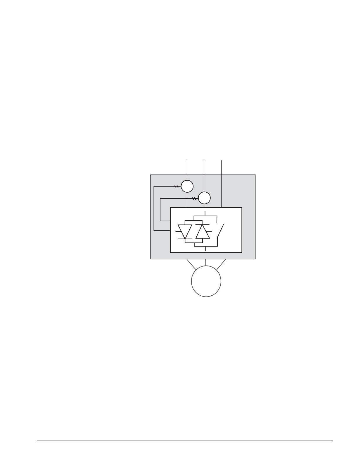
Built in Bypass After Acceleration
The bypass after acceleration allows the RVS-DX to control the motor during starting and stopping
for smooth, step-less acceleration and deceleration. However, once up to full voltage the RVS-DX is
bypassed to reduce the watt loss.
The RVS-DX incorporates internal bypass relays allowing current flow through the SCR’s only
during the soft start process. At the end of the soft start, the built-in relays bypass the SCR’s and
carry current to the motor. Upon stop signal, or in case of fault, all three bypass relays will open and
stop the motor. When the decel time is set to allow soft stopping, upon stop command, the bypass
relays will open immediately and the current will flow through the SCR’s. The voltage will then be
reduced slowly and smoothly to zero.
RVS-DX units rated 31-310 amps have built-in bypass.
C/T
C/T
M
x 3
RVS-DX, Digital Soft Starter Instruction Manual—04/01/04
2-4

chapter
3
RVS-DX Terminals and Wiring

This page intentionally left blank.
Control Terminals
Terminal Function Description
A1
A2
B1 Start/Stop
C1 Aux. Input
13
14
23
24
1. The control power should be connected to A2, and control neutral to A1.
2. The auxiliary input can be programmed to operate as a reset, dual adjustment, generator starting, slow speed, slow
speed reverse, or external fault (see chapter 6 on parameters to set the auxiliary input).
3.If the auxiliary output is set to Immediate, the contact closes at the start signal, and opens at the stop signal, end of soft
stop fault, or at loss of voltage. If the auxiliary output is set to End of Acceleration, the contact closes after acceleration
and opens at stop or soft stop signals, fault, or loss of voltage.
4. If the fault contact is set to fail-safe, the contact closes immediately when control power is connected, and opens upon
fault.
Control Supply
(Note 1)
Auxiliary Output
Contact
(Note 3)
Fault Contact
(Note 4)
120V control power must be connected at terminals A1 & A2.
Input from a N.O. maintained contact. Connect terminals A2 & B1 to start, and
open to stop.
Input from a N.O. maintained contact. Connect terminals A2 & C1 to operate
the function. (Note 2)
N.O. output contact can be set to Immediate or End of Acceleration. (Note 3).
N.O. contact closes upon any fault and returns to open position (after the fault
has been removed) upon reset, or disconnection of main supply voltage.
WARNING
Do not use the fault contact to trip an upstream contactor. When the fault contact trips the
upstream contactor, main voltage will be disconnected thus resetting the soft starter and the
motor will restart immediately upon power being restored.
WARNING
Start/stop with maintained contact. When the line contractor is operated by a maintained contact,
if main supply voltage is lost, the motor will automatically restart upon voltage restoration. When
resetting after a fault, the motor will restart upon the fault being reset.
RVS-DX, Digital Soft Starter Instruction Manual—04/01/04
3-3
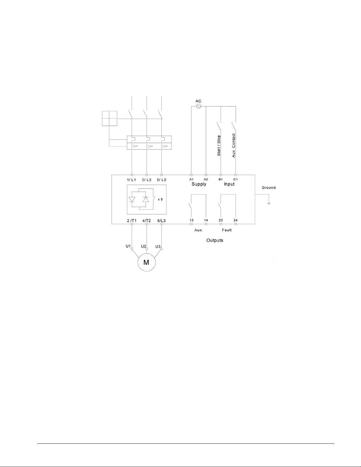
Typical Wiring Diagram
RVS-DX, Digital Soft Starter Instruction Manual—04/01/04
3-4

Operating “Inside the Delta”
Using the RVS-DX soft starter “inside the delta” reduces the required soft starter rating by 1.73 ( √3)
factor. For example, for a 150 amp, 460 volt motor, the RVS-DX-170-D is selected to operate in
standard “line” mode. However, for “inside the delta” mode (150 amp÷1.73=87 amps), the RVSDX-105-D can be selected, thereby, reducing cost and physical space in the application.
The following programming parameters are disabled, once the ‘inside the delta’ is selected:
• Pulse Start
• Pump Curve selection (only standard curve available)
• Slow Speed and Slow Speed Reverse
• Phase Sequence
The motor rating for standard “Line” and “Inside the Delta” connections are show here:
HP at 460V for
Model Number RVS-DX FLA
RVS-DX-8-D 8 5 7.5
RVS-DX-17-D171015
RVS-DX-31-D312032
RVS-DX-44-D443050
RVS-DX-58-D584068
RVS-DX-72-D725085
RVS-DX-85-D 85 60 100
RVS-DX-105-D 105 75 125
RVS-DX-145-D 145 100 170
RVS-DX-170-D 170 125 215
RVS-DX-210-D 210 150 250
RVS-DX-310-D 310 200 340
RVS-DX-390-D 390 300 515
“Line”
HP at 460V for
“Inside Delta”
HP Ratings are approximate. The RVS-DX should always be sized by the motor full load amps for
“line” starting and the motor FLA/1.73=soft starter FLA for “inside delta”.
RVS-DX, Digital Soft Starter Instruction Manual—04/01/04
3-5
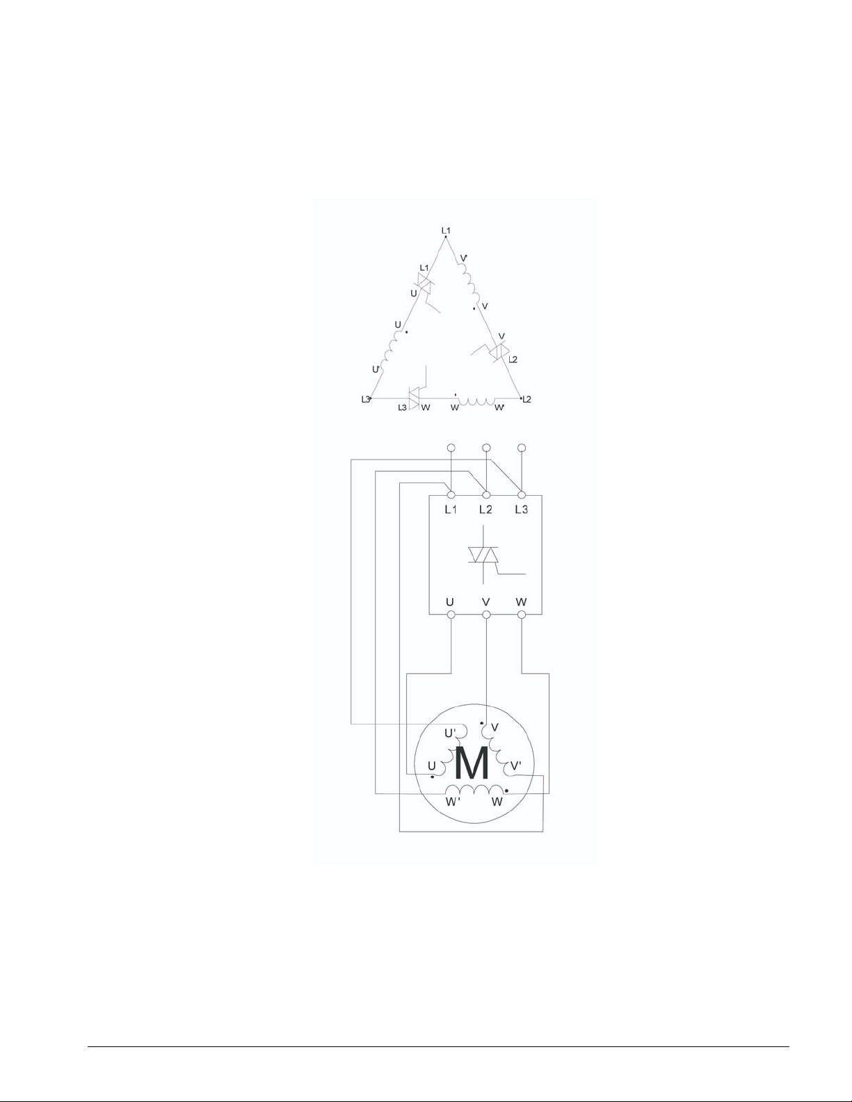
Typical Wiring for Inside the Delta Operation:
RVS-DX, Digital Soft Starter Instruction Manual—04/01/04
3-6

chapter
4
Control Layout
 Loading...