

Magnescale SR138-015R, SR138-020R, SR138-030R, SR138-035R, SR138-040R Instruction Manual
...
スケールセット/ Scale Set / Maßstab-Satz / 直线标尺组件
GB-ER/SR138R Series
スケールセット/ Scale Set / Maßstab-Satz / 直线标尺组件
GB-005ER~220ER
スケールユニット/ Scale Unit / Maßstabseinheit / 直线标尺器
SR138-005R~220R
お買い上げいただき、ありがとうございます。
ご使用の前に、この取扱説明書を必ずお読みください。
ご使用に際しては、この取扱説明書どおりお使いください。
お読みになった後は、後日お役に立つこともございますので、必ず保管してください。
Read all the instructions in the manual carefully before use and strictly follow them.
Keep the manual for future references.
Lesen Sie die ganze Anleitung vor dem Betrieb aufmerksam durch und folgen Sie beim Betrieb des Geräts den
Anweisungen. Bewahren Sie diese Bedienungsanleitung zum späteren Nachlesen griffbereit auf.
感谢您惠购本产品。
使用之前请务必认真阅读本手册,并且严格按照手册中的规定操作。将此手册留作以后的参考。
/
取扱説明書/ Instruction Manual / Bedienungsanleitung / 使用说明书

[For U.S.A. and Canada]
THIS CLASS A DIGITAL DEVICE COMPLIES WITH
PART15 OF THE FCC RULES AND THE CANADIAN
ICES-003. OPERATION IS SUBJECT TO THE
FOLLOWING TWO CONDITIONS.
(1) THIS DEVICE MAY NOT CAUSE HARMFUL
INTERFERENCE, AND
(2) THIS DEVICE MUST ACCEPT ANY
INTERFERENCE RECEIVED, INCLUDING
INTERFERENCE THAT MAY CAUSE
UNDERSIGNED OPERATION.
CET APPAREIL NUMÉRIQUE DE LA CLASSE A
EST CONFORME À LA NORME NMB-003 DU
CANADA.

■ 一般的な注意事項
■ 次の環境下で、ご使用になる場合の注意事項
以下は当社製品を正しくお使いいただくための一般的な注意事項で
す。個々の詳細な取扱上の注意は、本取扱説明書に記述された諸事
項および注意をうながしている説明事項に従ってください。
• 始業または操作時には、当社製品の機能および性能が正常に作動
していることを確認してからご使用ください。
• 当社製品が万一故障した場合、各種の損害を防止するための十分
な保全対策を施してご使用ください。
• 仕様に示された規格以外でのご使用、または改造を施された製品
については、機能および性能の保証はできませんのでご留意くだ
さい。
• 当社製品をほかの機器と組み合わせてご使用になる場合は、使用
条件、環境などにより、その機能および性能が満足されない場合
がありますので、十分ご検討の上ご使用ください。
1 水溶性切削液を使用する場合あるいは、金属微粉末が発生する
加工やセラミック•グラスファイバー等の加工物を加工する場
合。
• 水溶性切削液や切屑が直接スケールユニットに掛からない場
所へ取付けてください。
• 内部に水溶性切削液のミストや粉塵が侵入しないようスケー
ルカバーを付けてください。
2 ホーニングマシーンのような、長時間特定区間を高速摺動する
機械に装着する場合。
• 定期的にオイルまたはスプレー式潤滑油(CRC·WD40等)の
塗布をお願いします。
1または2の環境でご使用になる場合は必ず上記対策をしてくださ
い。行なわない場合は品質保証しかねます。
(J
) i
安全のために
当社の製品は安全に十分配慮して設計されています。しかし、操作や設置時にまちがった取
扱いをすると、火災や感電などにより死亡や大ケガなど人身事故につながることがあり、危
険です。また、機械の性能を落としてしまうこともあります。
これらの事故を未然に防ぐために、安全のための注意事項は必ず守ってください。操作や設
置、保守、点検、修理などを行なう前に、この「安全のために」を必ずお読みください。
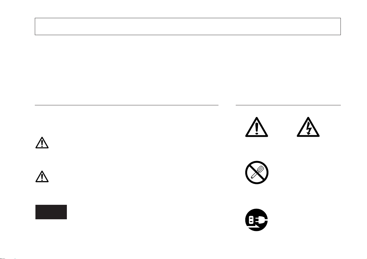
警告表示の意味
このマニュアルでは、次のような表示をしています。表示内容を
よく理解してから本文をお読みください。
警告
この表示の注意事項を守らないと、火災や感電などにより死亡や
大ケガなど人身事故につながることがあります。
注意
この表示の注意事項を守らないと、感電やその他事故によりケガ
をしたり周辺の物品に損害を与えることがあります。
注意を促す記号
注意
感電注意
行為を禁止する記号
分解禁止
行為を指示する記号
ご注意
機器の正しい取扱のために、注意していただきたい事項です。
ii
(J)
プラグの取外し
警告
注意
• 表示された電源電圧以外での電圧で使用しないでください。火災や感電の原因となる
恐れがあります。
• 濡れた手での取付作業はおやめください。感電の原因となります。
• 本体を分解や改造したりしないでください。ケガの恐れや、内部回路が破損すること
があります。
• 作業を行なう前には、機械や装置の状況をよく確かめて作業の安全を確保してくださ
い。
• 電源やエアーなどの駆動源は必ず切って作業をしてください。火災や事故の原因とな
ります。
• 電源などを入れて動かす場合は、周辺機械や装置などに指を挟まれないように十分注
意してください。
(J
) iii
取付上の注意
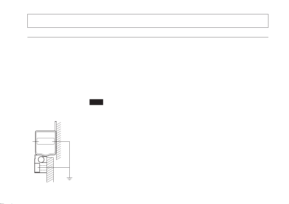
設置上のご注意
本機を設置されるときは、他の機器からのノイズ、電磁波障害などを防止するため、以
下の点に注意してください。
1. リードケーブルおよび接続ケーブルは、動力線と同じダクトには通さないでくださ
い。
2. 高電圧源、大電流源および大電力リレーからは必ず0.5m以上離して設置してくださ
い。
3. 各種マグネットや電磁波発生源を絶対に近づけないでください。
ご注意
• マグネットチャックなど6×10⁻²[T]程度の磁力源を近づける場合は、スケールユ
ニットのスチール製筐体側面より10 mm 以上、ダストリップ面より
50mm以上離してください。
• もし近づけなければならない場合は、磁気シールド対策を十分に施しご使用願い
ます。
4. ノイズによるトラブルを防ぐために、スケール部とスライダ部をグランドに落ちる
ように取付けてください。
iv
(J)

取付場所についてのご注意
1. スケールユニットは機械の加工物、測定物のできるだけ近くに取付けてください。
(スケールユニット取付位置が加工物より離れるほど、機械系の誤差が拡大されて表
示されます。)
2. 本製品は、周囲温度0〜40℃の範囲内でご使用ください。直射日光の当る場所や近く
にモーターなど、熱源のある場所への取付けは避けてください。
3. 取付けられたスケールユニットの上に物を置いたり、作業者がひじや足を掛けるな
ど、無理な力をかけることは絶対に避けてください。
(J
) v

vi
(J)

目次
1. 概要 .............................................................................. 2
1-1. はじめに ...................................................................... 2
1-1-1. SR138Rシリーズ ................................................. 2
1-1-2. CH04シリーズ .................................................... 2
1-1-3. GB-ERシリーズ .................................................. 2
1-1-4. CE10シリーズ ..................................................... 2
1-2. 主な特徴 ...................................................................... 2
1-3. 部品構成 ...................................................................... 3
1-4. システム構成 .............................................................. 3
2. 各部の名称と働き ........................................................ 5
2-1. スケールユニット...................................................... 5
2-2. 接続ケーブル .............................................................. 7
3. 取付方法 ....................................................................... 8
3-1. 取付け前の注意事項.................................................. 8
3-2. 取付け時の注意.......................................................... 9
3-2-1. 取付方向の確認 .................................................. 9
3-2-2. 可動範囲の設定 ................................................ 10
3-2-3. ヘッドケーブルの保護 .................................... 10
3-2-4. スケールカバーの取付け ................................ 10
3-3. 取付けに必要なもの................................................ 11
3-4. 取付方法 .................................................................... 12
〈1〉 スケール部取付面の平行度•平面度が
事前に出ている場合 ............................. 12
〈2〉 スケール部取付面が鋳肌面の場合 .............. 13
〈3〉 スライダ部の取付け .................................... 15
〈4〉 スライダホルダの取外し ............................. 18
〈5〉 可動範囲の確認 ........................................... 18
〈6〉 ヘッドケーブルの取付け ............................. 18
〈7〉 ケーブルの接続 ........................................... 19
〈8〉 コンジットケーブルの取付け ...................... 21
〈9〉 丸型コネクタの取付け ................................ 22
〈10〉インターフェースユニットを表示装置に
接続する場合 ............................................... 23
〈11〉インターフェースユニットを
コントローラに接続する場合...................... 24
〈12〉スケールユニットを取外す場合 .................. 24
4. 接続ケーブル回路の電気調整について ...................... 25
〈1〉 アッパーケースの取外し ............................. 25
〈2〉 SIN/COS信号確認 ...................................... 26
〈3〉 原点信号確認 ............................................... 28
〈4〉 原点位置確認 ............................................... 30
5. 主な仕様 ..................................................................... 33
5-1. 一般仕様 .................................................................... 33
5-2. 外形寸法図 ................................................................ 34
6. トラブルインフォメーション .................................... 37
日本語
(J
) 1

1. 概要
日本語
1-1. はじめに
1-1-1. SR138Rシリーズ
SR138Rシリーズは原点内蔵型直線スケールです。
スケール部とスライダ部の相対位置関係がスライダホルダ
にて位置調整され、固定されています。
必ず別売りの接続ケーブルCH04とセットでご使用くださ
い。
ご注意
SR138RシリーズとCH04を別々に購入された場合は、使用
する前にCH04の電気調整が必要となります。ご購入時に電
気調整を依頼された場合は、調整は必要ありません。
1-1-2. CH04シリーズ
SR138Rシリーズの信号を汎用のA/B相出力に変換する回路
を内蔵した専用ケーブルです。SR138Rシリーズと組み合わ
せることで、当社の表示ユニット(LH71等)やコントローラ
などの外部機器に接続することができます。
1-1-3. GB-ERシリーズ
GB-ERシリーズは、SR138Rシリーズと電気調整済みの接続
ケーブルCH04-03Cが同梱されている製品です。
ご注意
SR138RシリーズのSerialNo.とCH04-03Cのコンビネーショ
ンNo.が必ず同一の物同士を組み合わせてご使用ください。
1-1-4. CE10シリーズ
ケーブルを延長する場合の別売りの延長ケーブルです。
CH04との組み合わせで最大30mまで延長可能です。
1-2. 主な特徴
• 小型• 軽量• 原点内蔵
• 取付けが簡単
• 機械と同じ温度膨張係数
• 高精度な位置検出
• 油• 汚れに強い
2
(J)
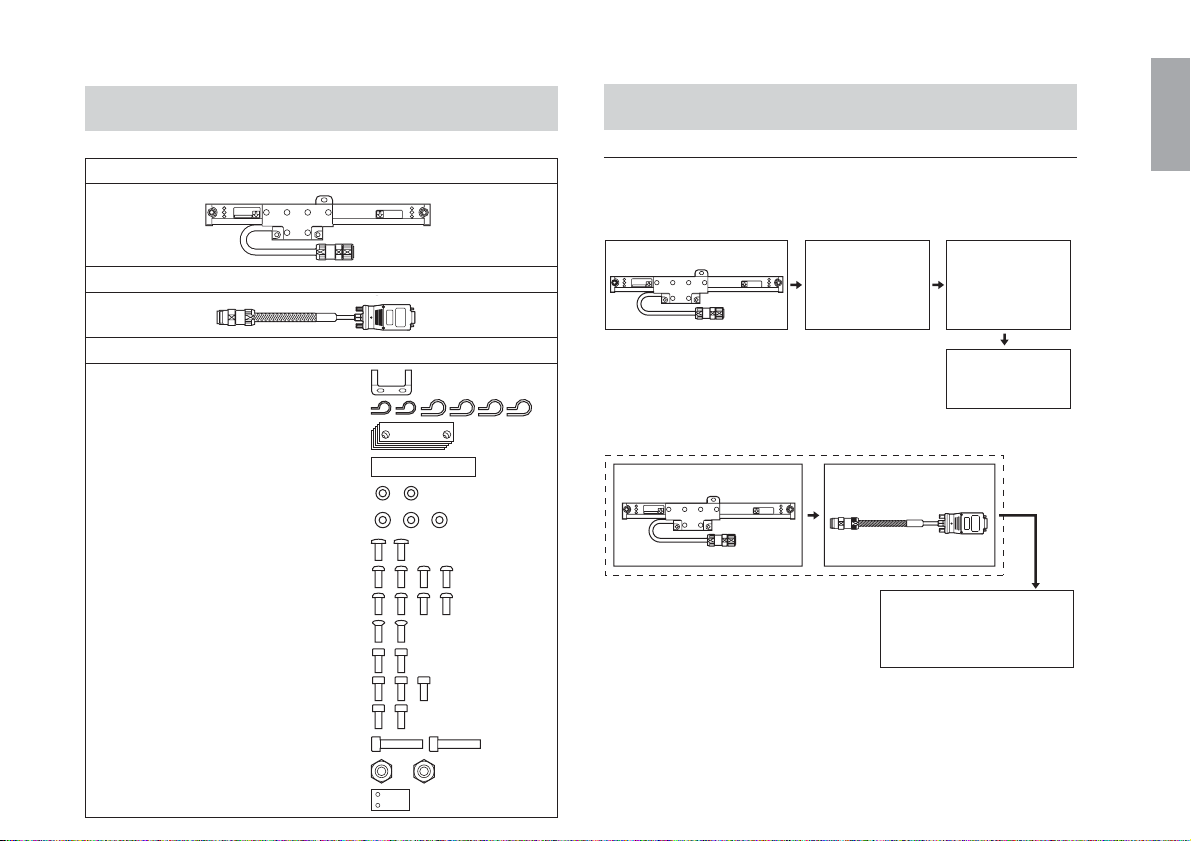
1-3. 部品構成
1-4. システム構成
スケールユニット ............................................................. 1
接続ケーブル(CH04:GB-ERシリーズにのみ同梱) ........ 1
付属品
クランプ ........................................ 1
配線止め ............................. 小2,大4
スペーサ ........................................ 5
目隠しラベル ................................. 1
平ワッシャ(S) .............................. 2
平ワッシャ(M) .............................. 3
+B4×10 .......................................... 2
+P4×5 ............................................ 4
+P4×10 .......................................... 4
+K3×5 ............................................ 2
HSBM4×8 ..................................... 2
HSBM4×10 ................................... 3
HSBM4×12 ................................... 2
HSBM5×25 ................................... 2
ナット(M5) ................................... 2
固定板 ............................................ 1
システム接続構成
• SR138Rシリーズ
スケールユニット
延長ケーブル
(別売)
• GB-ERシリーズ
スケールユニット(SR138R) 接続ケーブル
(CH04-03C)
接続ケーブル
(別売)
表示ユニット
(別売)
CH01-**C
COMBINATION No.
******
MADE IN JAPAN
表示ユニット
LH71シリーズ等、
コントローラ
(別売)
(J
日本語
) 3
日本語
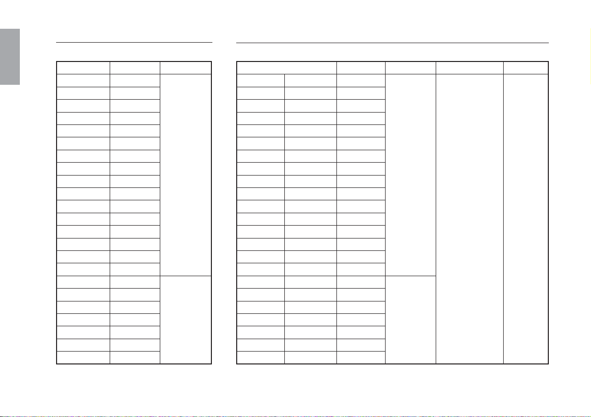
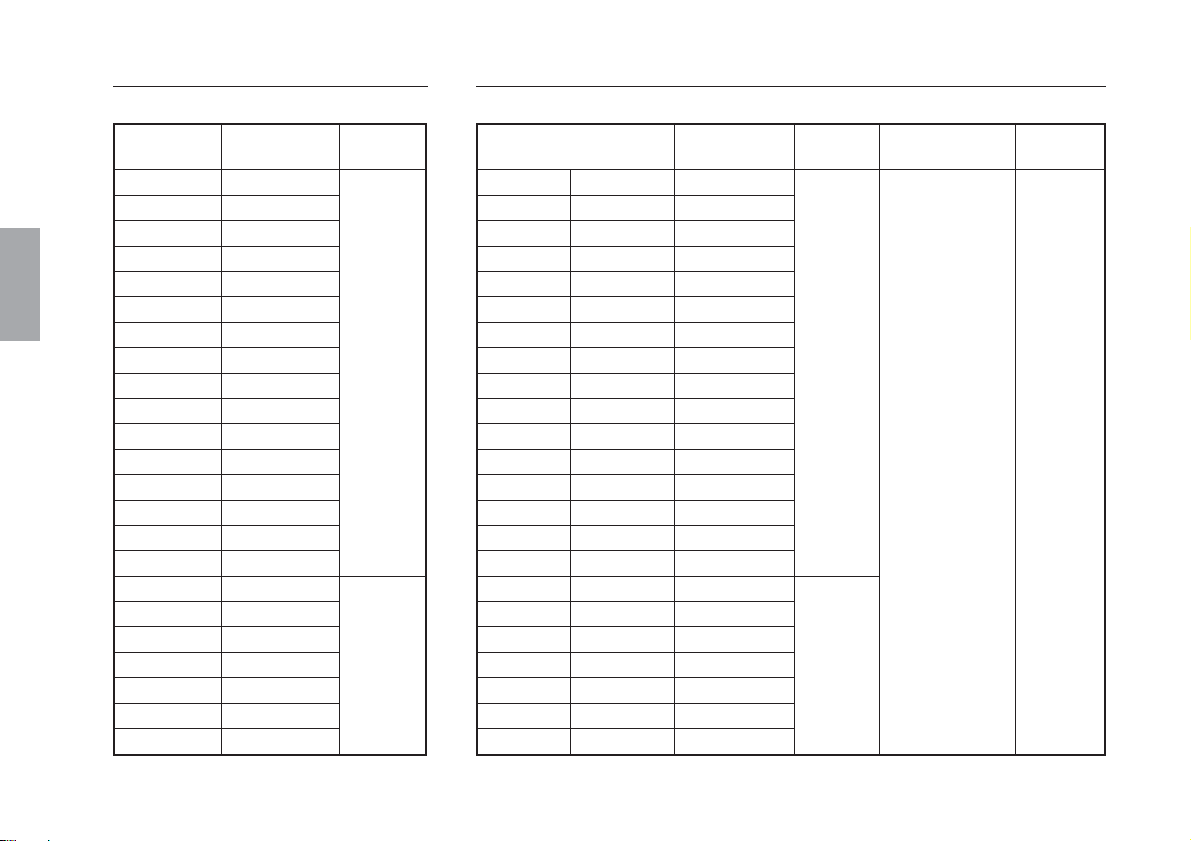
機種構成(SR138Rシリーズ)
型名
SR138-005R
SR138-010R
SR138-015R
SR138-020R
SR138-025R
SR138-030R
SR138-035R
SR138-040R
SR138-045R
SR138-050R
SR138-055R
SR138-060R
SR138-065R
SR138-075R
SR138-085R
SR138-095R
SR138-105R
SR138-125R
SR138-140R
SR138-160R
SR138-185R
SR138-205R
SR138-220R
有効長(L)
50mm
100mm
150mm
200mm
250mm
300mm
350mm
400mm
450mm
500mm
550mm
600mm
650mm
750mm
850mm
950mm
1050mm
1250mm
1400mm
1600mm
1850mm
2050mm
2200mm
中央フット
無し
有り
機種構成(GB-ERシリーズ)
有効長(L)
1050mm
1250mm
1400mm
1600mm
1850mm
2050mm
2200mm
GB-005ER
GB-010ER
GB-015ER
GB-020ER
GB-025ER
GB-030ER
GB-035ER
GB-040ER
GB-045ER
GB-050ER
GB-055ER
GB-060ER
GB-065ER
GB-075ER
GB-085ER
GB-095ER
GB-105ER
GB-125ER
GB-140ER
GB-160ER
GB-185ER
GB-205ER
GB-220ER
型名 中央フット
SR138-005R
SR138-010R
SR138-015R
SR138-020R
SR138-025R
SR138-030R
SR138-035R
SR138-040R
SR138-045R
SR138-050R
SR138-055R
SR138-060R
SR138-065R
SR138-075R
SR138-085R
SR138-095R
SR138-105R
SR138-125R
SR138-140R
SR138-160R
SR138-185R
SR138-205R
SR138-220R
50mm
100mm
150mm
200mm
250mm
300mm
350mm
400mm
450mm
500mm
550mm
600mm
650mm
750mm
850mm
950mm
無し
有り
接続ケーブル型名
CH04-03C
ケーブル長
3m
4
(J)
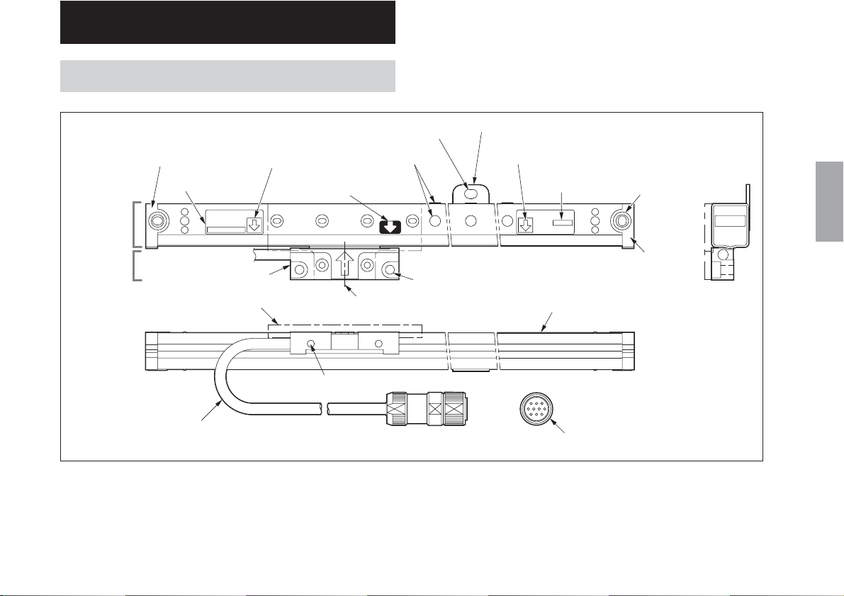
2. 各部の名称と働き
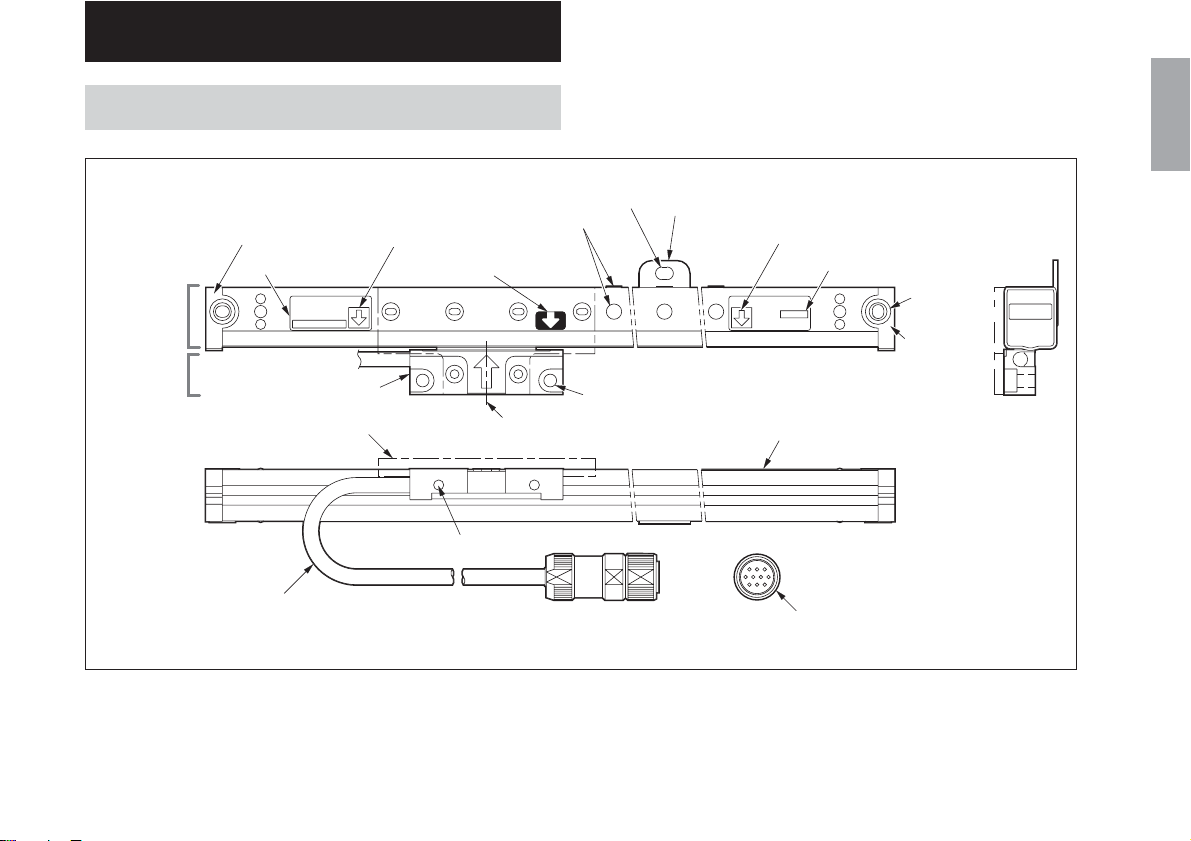
2-1. スケールユニット
サイドカバーL
型名
6
スケール部
スライダ部
SR138−***R
スライダ
スライダホルダ
5
3
1
中央フットプレート固定穴
アライメントマーク
有効長マーク(左)
原点マーク
4
2
スライダ取付穴
スライダ取付穴
スライダ中心
中央フットプレート
7
スケール本体
有効長マーク(右)
3
Serial No.
******
SerialNo./原点位置表示
8
スケール
取付穴
(両端2箇所)
サイド
カバーR
日本語
ヘッドケーブル
1 スライダ
検出ヘッドを保持しています。出荷時にはスライダホ
ルダで固定されています。
丸型コネクタ(オス)
2 スライダ中心
スライダのメカニカルセンタを表わします。有効長
マークとの位置関係を見る目安となります。
(J
) 5

日本語
3 有効長マーク
スライダ中心に対して、精度を保証する有効可動範囲
の目安を指示するマークです。有効長とは、有効可動
範囲の長さを表します。
ご注意
取付け、およびご使用の際に、この範囲内で可動させ
てください。有効可動範囲を超えて使用すると、本製
品を破損させる原因となります。
4 原点マーク
スライダ中心に対して、原点信号が出力される位置の
目安を指示するマークです。
標準仕様では、有効長の中央に1箇所の原点が存在しま
す。
5 スライダホルダ
スケール部とスライダ部を固定します。取外した後は
保管してください。
6 型名
本製品の型名を明記してあります。
7 中央フットプレート
有効長1050mm以上の場合に取付けられています。ス
ケールユニット取付けの際は、この部分も固定しま
す。
8 SerialNo./原点位置表示
本製品のSerialNo.とスケール本体の原点位置を明記し
てあります。
GB-ERシリーズの場合、組み合わせる接続ケーブルの
コンビネーションNo.と同一になっています。
ご注意
本スケールシステムは、スケールユニットのSerialNo.
と接続ケーブル(CH04シリーズ)のコンビネーション
No.が必ず同一の物同士を組み合わせてご使用くださ
い。
6
(J)
1
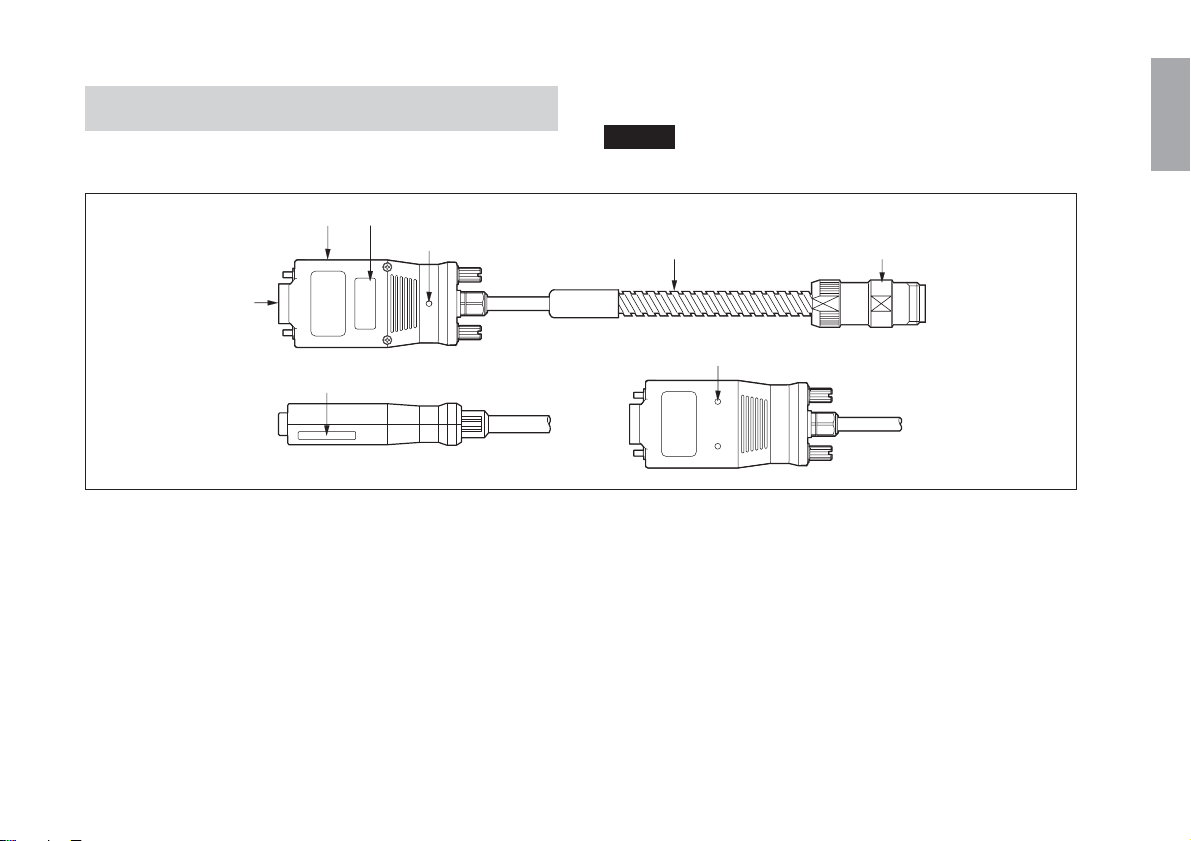
2-2. 接続ケーブル
CH04:GB-ERシリーズのみに同梱されています。
ご注意
別途購入された場合は、電気調整が必要となります。
日本語
インターフェースユニット
出入力コネクタ
5
6
型名
3
ステータスランプ
7
CH04-03C
コンビネーションNo.
1 インターフェースユニット
表示ユニットの背面に接続します。
最適に電気調整された回路が組み込まれています。
2 コンジットケーブル
内部のケーブルを保護しています。
3 型名
本製品の型名を明記してあります。
4 丸型コネクタ(メス)
スケールユニット側の丸型コネクタ(オス)と接続します。
5 入力コネクタ
電源としてDC+5[V]を供給することにより、スケール
信号と原点信号が出力されます。
丸型コネクタ(メス)コンジットケーブル
2
インターフェ−スユニット固定用タップ
8
4
6 コンビネーションNo.
GB-ERシリーズの場合、組み合わせるスケールユニッ
トのSerialNo.と同一になっています。
7 ステータスランプ
信号確認用のランプです。
緑色点灯:正常
赤色点灯:エラー(速度超過、ケーブル断線、信号不良)
8 インターフェースユニット固定用タップ
インターフェースユニットを固定する場合、付属の固
定板とねじを用いて固定できます。(M3深さ3mm)
(J
) 7

3. 取付方法
日本語
3-1. 取付け前の注意事項
取付前に、必ず「取付け時の注意」をご確認ください。
分解禁止
<スケールユニット>
• スケールユニットは分解しないでください。精度が保証
できなくなります。スライダホルダのみ取外し可能で
す。
<接続ケーブル>
• 接続ケーブルは調整されていますので分解しないでくだ
さい。精度が保証できなくなります。
• SR138Rで別途購入された接続ケーブルは、電気調整のた
めのケース取外しが必要ですが、それ以外の分解は行な
わないでください。
無理な力をかけない
• 作業時に、スケールユニットに無理な力をかけないでく
ださい。スケールユニットは精密機構部品および電磁気
部品で構成されています。無理な力を加えると性能や寿
命に大きな影響を与えます。
• 作業時に、接続ケーブルのインターフェースユニットに
無理な力をかけないでください。インターフェースユ
ニット内部には精密電気部品が実装、調整されていま
す。無理な力を加えると性能や寿命に大きな影響を与え
ます。
• 持ち運びの際は、スケール部とスライダ部を共に支えて
ください。ヘッドケーブルや丸型コネクタなどを持って
運ばないでください。
8
(J)
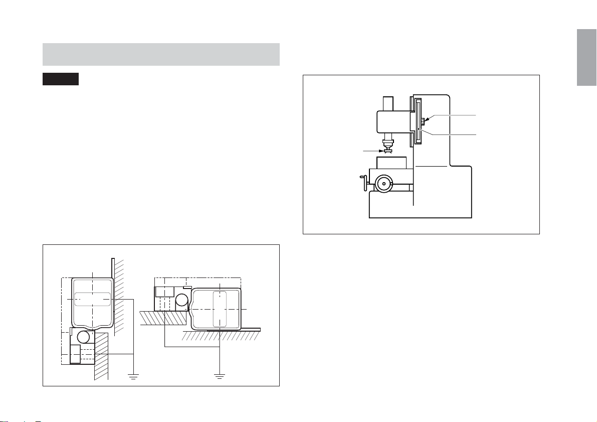
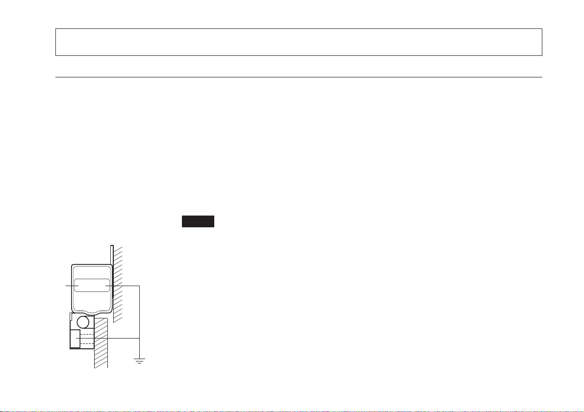
3-2. 取付け時の注意
上下軸に取付ける場合は、スケールユニットのスライダ部
が加工物(刃物)と反対側を向くように取付けてください。
ご注意
ノイズによるトラブルを防ぐために、スケール部とスライ
ダ部をグランドに落ちるように取付けてください。
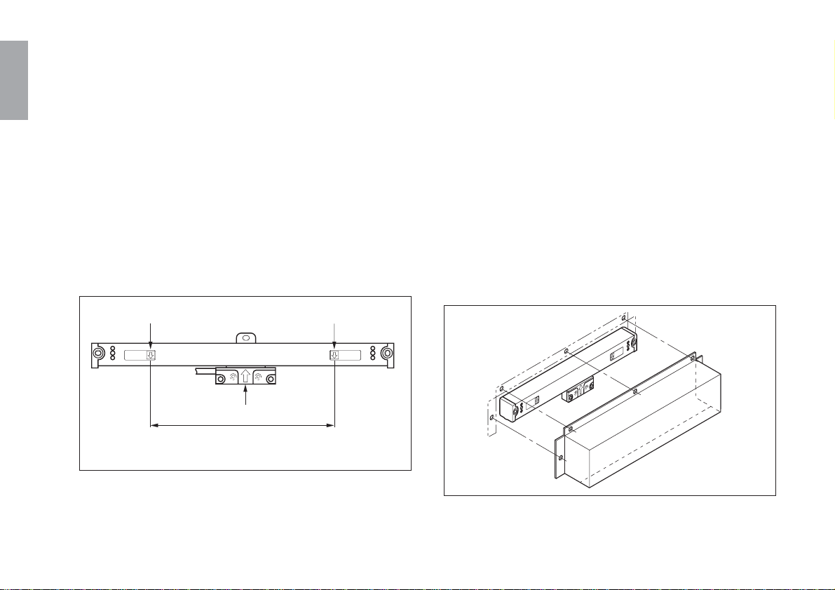
3-2-1. 取付方向の確認
本スケールユニットが、図3-1のような位置関係に取付くこ
とを確認してください。
*
その他の向きはサービス、メンテナンスに不都合なため使
用しないでください。
(切削液や切粉の侵入を防ぐため、Aの取付けを特におす
すめします。)
(B方向取付けは、切削液や切粉の進入がない場合のみ取
付可能です。)
推奨
A
B
日本語
スライダ部
スケール部
加工刃物
図3-2.上下軸スケールユニットの取付位置と方向
図3-1.スケールユニット取付方向
(J
) 9
3-2-2. 可動範囲の設定
3-2-3. ヘッドケーブルの保護
日本語
スケールユニット取付時は図3-3の可動範囲で取付けてくだ
さい。
• スケールユニットには可動余裕(有効長200mmまで左右
7mm,有効長250mm以上左右15mm)がありますが、そ
れ以上にスライダ部を移動させますとスケール部が破損
しますのでご注意ください。
• スケールユニットの有効可動範囲を超える工作機械に
は、機械的な制限機構(ストッパなど)が必要です。
必ず、このような処置を施してからスケールユニットを
取付けてください。
有効長マーク
スライダ中心
この範囲内にスライダ中心がくるように取付けてください。
(有効可動範囲)
図3-3.可動範囲
有効長マーク
ヘッドケーブルはスケールユニットと一体構造になっています
のでケーブルに負荷がかからないように取付けてください。
ヘッドケーブルを強く引張ったり繰返し折り曲げたりしま
すと、断線する恐れがあります。ご注意ください。
3-2-4. スケールカバーの取付け
ご使用中、スケールユニットに直接切粉や切削液などが降
りかかる場合には、スケールユニットの性能維持のために
も図3-4のような外部からスケールユニットを覆うカバーを
取付けてください。
10
図3-4.スケールカバーの取付け例
(J)

3-3. 取付けに必要なもの
付属品一式
六角穴付ボルト M4×10 スケール部取付用 ................. 3
(有効長1000mm未満は2本)
六角穴付ボルト M4×8 スライダ部取付用................. 2
M4×12 スライダ部取付用 ................. 2
小ねじ M4×5 配線止め用(小) .................... 2
M4×10 配線止め用(大) .................... 4
M4×5
M3×5 固定板取付用 ......................... 2
平ワッシャ(M) みがき丸呼び4スケール部取付用..... 3
(有効長1000mm未満は2個)
平ワッシャ(S) 小型丸 呼び4 スライダ部取付用 ... 2
配線止め(大) コンジットケーブル取付用 ................. 4
目隠しラベル スライダホルダ取外し後
ねじ穴隠し用 ......................................... 1
六角穴付ボルト M5×25 スライダ部取付用 ................. 2
六角ナット M5 スライダ部取付用................. 2
スペーサ t=0.1 スライダ部取付用 ................. 5
クランプ 丸型コネクタ取付用 ............................. 1
バインド小ねじ M4×10 クランプ取付用 ..................... 2
配線止め(小) ヘッドケーブル固定用 ......................... 2
固定板 インターフェースユニット固定用 ..... 1
インターフェースユニット
取付用 ....
付属品以外に下記のものをご用意ください。
スケール部取付用ブラケット(A,B面相当部品) .......... 1〜2
スライダ部取付用ブラケット(C面相当部品) ..................... 1
0.01mmピックテスター(またはダイヤルゲージ) ....... 1〜2
Lレンチ M2.6用(対辺2mm) ............................................... 1
Lレンチ M4用(対辺3mm) .................................................. 1
Lレンチ M5用(対辺4mm) .................................................. 1
タップ M4 ............................................................................ 1
2
ドリル ø3.2 ........................................................................... 1
電気ドリル ................................................................................. 1
ライナ•スペーサ(0.05〜0.2t) ........................................... 少々
ドライバ2号(+) ........................................................................ 1
モンキスパナ(小)..................................................................... 2
(J
日本語
) 11
日本語
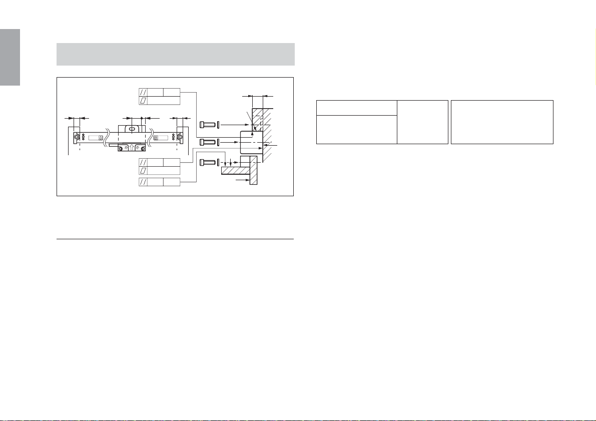
3-4. 取付方法
0.1 MG
0.1
25 12 25 25
0.1 MG
0.1
0.1 MG
図3-5.取付方法
〈1〉 スケール部取付面の平行度•平面度が事前に出
ている場合
取付面が機械加工面で、事前に下表の平行度、平面度が出
ていれば、そのままスケール部を取付けることができま
す。
有効長1050mm未満(中央フットプレート無し)のスケール
ユニットの場合
使用ねじ / 締め付けトルク:六角穴付ボルトM4× 10
(2本)、平ワッシャ(M)2個使用/350N·cm
8 以上
A
B
D
C
有効長1050mm以上(中央フットプレート有り)のスケール
ユニットの場合
使用ねじ / 締め付けトルク:六角穴付ボルトM4× 10
(3本)、平ワッシャ(M)3個使用/350N·cm
A面,B面平面度
A面,B面機械の走り 0.1mm以内
に対する平行度
A面:スケール部突き当て
B面:スケール部取付面
面
A面は図3-5で示す範囲としてください。ただし、上記許容
値は平面内に急激な変化がないことと、左右取付面の間に
スケール部を取付けるのに障害がないことが条件となりま
す。
12
(J)
〈2〉 スケール部取付面が鋳肌面の場合
取付ブラケットによる取付け
(1) 取付面が鋳肌面などで平行度が出ていない面のとき
スケール部設置位置に取付ブラケットを取付けて〈1〉
項の値になるように調整してください。
取付ブラケットはスケール部の左右フット部分にあれ
ば、スケール部全長に渡ってある必要はありません。
取付機械の可動長により左右フットの平行度が測定で
きない場合には、測定できる範囲まで取付ブラケット
を長く作ってください。
機械との温度追従性が問題となる場合は、スケールユ
ニット全長に渡り取付ブラケットを配置するようにし
てください。
A面の平行度測定
日本語
取付ブラケット
ピックテスター
B面の平行度測定
図3-6.取付ブラケットの平行度測定
取付ブラケットの形状として突き当て面があれば、こ
の面精度を〈1〉項の値になるように調整してくださ
い。突き当て面が無い場合には(4)に示す方法で調整し
てください。また、取付面の精度が得られないとき
も、(4)に示す方法で調整してください。
(J
) 13
日本語
(2) 取付位置の確認とねじ穴加工
スケール部の取付平行度が出たら、外形寸法図(P34)に
したがって取付穴の位置にそれぞれM4深さ10のタップ
穴を作ってください。
(3) スケール部の取付け
スケール部は平ワッシャ(大)を付けた六角穴付ボルト
M4×10で仮止めし、30分以上放置して温度をよく機械
になじませてから取付けを行なってください。
(4) スケール部と機械の走りとの平行度測定
スケール部側面のアライメントマーク位置(図3-7、1)
に直接ピックテスターまたはダイヤルゲージを当て、機
械の走りに対してスケール部の平行を出してください。
2
1
平行度はアライメントマークの2点間が0.08mm以内に入る
ように調整して、取付ねじを固定してください。
有効長1050mm以上の場合は、中央フットプレート付近と
左右のアライメントマークの3点間が0.08mm以内に入るよ
うにして取付ねじを固定してください。
ご注意
有効長150mm以下のスケール部にはアライメントマークが
付いていませんので、スケール部にピックテスターを当
て、機械の可動長の両端が0.08mm以内に入るようにして
ください。
フット
行度0.08mm以内
平
中央フットプレート
14
(J)
アライメントマーク
図3-7.スケール部と機械の走り測定
フット
平ワッシャ(M)
アライメントマーク
アライメントマーク
アライメントマーク
M4×10
図3-8.アライメントマークによる平行出し
(5) スケール取付ブラケットの平行度が出せないとき
図3-7の2の位置にピックテスターまたはダイヤルゲー
ジを当てて各アライメントマークを計り、0.08mm以内
の平行度になるようにフットの下部にスペーサなどを
入れて取付けてください。
中央フットプレート付のスケールユニット(有効長
1050〜2200mm)については、中央フットプレート付
近の位置も0.08mm以内の平行度に入れてください。
〈3〉スライダ部の取付け
(1) 取付面の平行度、平面度が事前に出ているとき
取付面が機械加工面で、事前に下の平行度、平面度が
出ていれば、そのままスライダ部を取付面に取付ける
ことができます。
使用ねじ / 使用ワッシャ:六角穴付ボルトM4× 12
(2本)、平ワッシャ(S)2個使用
締め付けトルク:350N·cm
日本語
C、D面平面度
0.05mm以内
C、D面機械の走りに対する平行度
B面〜C面間の平行度
0.05mm/
60mm以内
B面〜D面間の平行度
B面〜C面の間隔
8.7〜8.8mm
A面:スケール部突き当て面
B面:スケール部取付面
C、D面:スライダ部取付面
取付面がスライダ部の下にくるように機械を動かしま
す。
付属のスペーサで取付面とスライダ部の隙間を埋めて
から、スライダ部を固定してください。その後スライ
ダホルダを止めているねじを外してください。このと
き、スライダ部とブラケットが当らないように注意し
て機械を動かしてください。
(J
) 15
日本語
【付属のスペーサt=0.1mm(5枚)でスライダ部の隙間を
埋められなかった場合】
その状態で、スライダホルダのスライダ部を止めてい
るねじを緩め、スライダ部をスケール部に押し当てな
がらボルトで固定してください。
(2) B-C面の間隔を9mmに設定した場合
スライダホルダを止めているねじを緩め、スライダ部を
手で動かしブラケットに合わせ、図3-9の42±0.2mm寸法
の位置で止めてください。スペーサは必要ありません。
ご注意
スライダホルダを止めたまま、ブラケット側を動かす
と、スライダ部に当たる恐れがありますので、この方
法では行なわないでください。
42±0.2
8.7〜8.8
(3) スライダ部取付面が精度出しされていない場合
機械本体の取付面が鋳肌面の場合は、取付ブラケット
を使用します。
スライダホルダを固定しているねじを緩めずに、スラ
イダ部下面と取付ブラケットを合わせ、ブラケットの
高さを調整しながらボルト固定してください。
スケール部
図3-10.
2-平ワッシャ(小)
2-M4×12
(付属品)
4〜6t
スライダ部
スライダホルダ
取付ブラケット
17以下
16
BC
図3-9.
(J)
(4) スライダ部の上側にブラケットを取付ける場合
スライダ部上面と取付ブラケットを合わせて、スケー
ル部取付面からの高さが21±0.1mmになるように取付ブ
ラケットを調整してください。取付ブラケットはスラ
イダホルダ凸部を逃げた形状にしてください。図3-11の
ようにスライダ部をボルト(六角穴付ボルト)M5×25
(2本)とナットM5(2個)で固定します。
スライダ凸部
(5) スライダ部の背面にブラケットを取付ける場合
スライダホルダを固定しているねじを緩めずに、スラ
イダ部背面と取付ブラケットを合わせ、ブラケットの
高さを調整しながら付属ねじM4×8(2本)で固定してく
ださい。
42±0.2
4t
日本語
2-ø5.5
取付用ブラケット
9
7
2-M5×25
(付属品)
37
6~8t
21±0.1
2-M5ナット
(付属品)
スライダ部
取付ブラケット
2-M4×8(付属品)
15
図3-12.
図3-11.
* スライダ部の有効ねじ深さは4.5mmです。
取付ブラケットが4mmより薄い場合は、ワッシャで
厚さを調整してください。
(J
) 17
〈4〉スライダホルダの取外し
〈5〉可動範囲の確認
日本語
18
スライダホルダの取付ボルトM2.6(4本)を外し、スライダ
ホルダを取外します。
• 取外し後のねじ穴は必ず目隠しラベル(付属品)を貼って
ふさいでください。目隠しをしないと切削油、切粉、塵
埃が入って中のスケール精度に支障をきたす恐れがあり
ます。ラベルには取付年月日と担当者の名前をボールペ
ンで記入してください。
M2.6ボルト4本を外します。
スライダホルダ
目隠しラベル
(付属品)を貼ります。
図3-13.スライダホルダの取外し方
ご注意
取外したスライダホルダと残りのM2.6ボルト(4本)は保管
しておいてください。
(J)
スケール部とスライダ部取付後は必ず機械を全長にわたっ
て移動させて、スケール有効長と機械の移動量が有効長以
内であることを確認してください。
機械の移動量がスケールユニットの有効長+可動余裕量を超
えると、スケールユニットを破損させてしまいますのでご
注意ください。
〈6〉ヘッドケーブルの取付け
ヘッドケーブルは、邪魔にならないように配線止めで固定
します。
ご注意
ヘッドケーブルはスケールユニットと一体構造になっています
のでケーブルに負荷がかからないように取付けてください。
ヘッドケーブルを強く引張ったり繰返し折り曲げたりしま
すと、断線する恐れがあります。ご注意ください。
配線止め
小ねじM4×5で固定します(付属品)。
図3-14.
〈7〉ケーブルの接続
別売の延長ケーブル (CE10シリーズ) を使用すると、
SR138RおよびGB-ERシリーズと接続ケーブルの間を延長す
ることができます。
スケールユニット
延長ケーブル(CE10-**C)
ケーブル長
CE10-**C
44 44
ø18
丸型コネクタ(メス)
ご注意
ケーブルを延長した場合の最大総ケーブル長は、30mまで
となっています。
接続ケーブル(CH04-03C)
**
ø18
ø9
丸型コネクタ(オス)
単位:mm
型名
CE10-01C
CE10-03C
CE10-05C
CE10-10C
日本語
ケーブル長
1m
3m
5m
10m
図3-15.
(J
) 19
日本語
ご注意
• GB-ERシリーズは、必ずスケールユニットのSerialNo.と
接続ケーブルのコンビネーションNo.が同じ組合わせで接
続してください。
• SR138Rシリーズと、別売の接続ケーブル(CH04シリー
ズ)を、電気調整をご依頼されてお求めになられた場合
は、GB-ERシリーズと同様にスケールユニットのSerial
No.と接続ケーブルのコンビネーションNo.が同じ組合わ
せで接続してください。
• 別売の接続ケーブル(CH04シリーズ)を単品でお求めの場
合、必ず電気調整が必要となります。
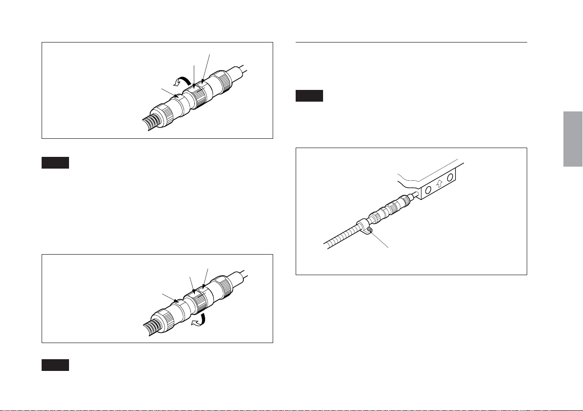
1
2
メス側
B部
メス側
切り欠き部を合わせる
C部
A部
手でまわす
カップリングナット
図3-16.
オス側
オス側
20
(J)
3 A部とB部にスパナを
かけて矢印方向に回す
メス側
3/4回転
B部
図3-17.
A部
C部
オス側
ご注意
• スパナ等の工具を用い、締付トルク150〜250N·cmで接続
してください。規定トルクで締付けないと防水性能が保
証されません。
• A部とC部にスパナをかけて締めることは行なわないでく
ださい。
〈8〉コンジットケーブルの取付け
コンジットケーブルは、邪魔にならないように配線止めで
固定します。
ご注意
このとき、機械の動作に対して、余裕をもたせて配線する
必要があるので、ご注意願います。
日本語
外す場合
A部とC部にスパナを
かけて矢印方向に回す
メス側
C部
A部
B部
図3-18.
オス側
ご注意
• A部とB部にスパナをかけて緩めることは行なわないでく
ださい。
配線止め
小ねじM4×10で固定します(付属品)。
図3-19.
(J
) 21
日本語
〈9〉 丸型コネクタの取付け
接続されたオス―メスの丸型コネクタを、付属品のクラン
プで固定します。
コネクタは、固定されていないと危険ですので、必ず固定
してください。
1 クランプの開口部側からコネクタにはめ込みます。
2 +BM4×10(2本,付属品)でクランプの上下を共締めす
るように押付けます。
3 クランプの上下が突き当たるまで、しっかりとねじを
締付けます。
コネクタが固定されていることを確認します。
クランプ取付寸法および外形寸法
34
4.4
30
54
6
クランプ
+B(バインド小ねじ)
M4×10で締付けます。
22
取付後の高さ寸法は、コネクタ外形と同じとなります。
(J)
突き当たるまで締付けます。
図3-20.

〈10〉 インターフェースユニットを表示装置に接続
する場合
SR138Rシリーズで接続ケーブルとの電気調整が必要な場
合、「4.接続ケーブル回路の電気調整について」に進んで
ください。
1 表示ユニットの電源がOFFになっていることを確認
し、接続ケーブルのインターフェースユニットを表示
ユニット背面の1〜3のコネクタに接続します。
ご注意
スケールユニット取付軸と表示ユニット差込みを確認して
ください。
2 インターフェースユニットのねじを用いて固定しま
す。(締付けトルク:60N·cm)
日本語
インターフェース
ユニット
表示ユニット背面
図3-21.
(J
) 23
日本語
〈11〉 インターフェースユニットをコントローラに
接続する場合
1 付属の固定板を小ねじ(M3×5)でインターフェースユ
ニットに取付けます。
21を付属の小ねじ(M4×5)で取付面に固定します。
ご注意
取付面にはM4タップ2箇所を準備してください。
20
〈12〉 スケールユニットを取外す場合
一度機械に取付けられたスケールユニットを取外す場合は
スライダホルダを必ず使用し、スライダ部をスケール部に
固定します。
番号順に行なってください。
2 ボルトM2.6(4本)で固定します。
1 目隠しラベルを剥がします。
3 ねじを緩め機械から
外します。
図3-23.スケールユニットの取外し方
24
(J)
図3-22.
このように固定することにより、スケール部とスライダ部
は取付時と同じ状態に再現されますので、再度取付ける場
合は容易に取付けられます。
4.
接続ケーブル回路の電気調整について
(SR138Rシリーズのみ)
* この項目は、最適調整されて組み合わせ出荷されている
GB-ERシリーズには必要ありません。
SR138Rシリーズを表示ユニットと接続する場合、接続ケー
ブルとしてCH04シリーズ(別売)をご使用ください。
接続ケーブルは、使用するスケールユニットと必ず一体で
電気調整する必要がありますので、以下の手順に従い調整
してください。
電気調整は、スケールユニットからのA/B相信号を最適化
するために行ないます。したがって、規定通りに調整され
ない場合、スケール精度仕様が満足されません。
ご注意
ただし、スケールユニットと表示ユニット接続ケーブル
(CH04シリーズ)を一体で注文された場合は、調整して出荷
されますので調整の必要はありません。スケールユニット
のSerialNo.と接続ケーブル側のコンビネーションNo.が同
じ組合わせで接続してください。
準備するもの
• オシロスコープ
(感度0.01V以上,周波数帯域 1MHz以上のもの)
入力感度 : DC0.1V/div(10:1プローブ使用)
水平軸掃引 : 50ms/div〜0.5ms/div
トリガソース : INT
トリガモード : AUTO
• マイナスドライバ(トリマ回転用)
• プラスドライバ(アッパーケース取付・取外し用)
〈1〉アッパーケースの取外し
インターフェースユニットのアッパーケースを取付けている
M2×8(2本)ねじを取外し、アッパーケースを外します。
M2×8
アッパーケース
日本語
図4-1.
(J
) 25
日本語
〈2〉SIN/COS信号確認
ご注意
• オシロスコープのプローブの取付け、取外しは、イン
ターフェースユニットの電源がOFFの状態のときに行
なってください。
• インターフェースユニットのチェック端子は、小さく物
理的強度がないため、ICクリップ等を用いて接続してく
ださい。(推奨ICクリップ:テクトロニクス製 グラバ•
クリップSMG50等)
オシロスコープ
CH1CH2
プローブ
インターフェースユニット
CN2-5pin (Z)
26
• インターフェースユニットの電源がOFFになっているこ
とを確認してください。
• インターフェースユニットカバーの取外し、取付けは、
「アッパーケースの取外し」を参照してください。
1 インターフェースユニットのチェック端子のTP1(SIN)
とTP4(GND)に、オシロスコープのCH1プローブを接
続します。
2 インターフェースユニットのチェック端子のTP2(COS)
とTP4(GND)に、オシロスコープのCH2プローブを接
続します。
(J)
スイッチ1
(原点POS1sw)
スイッチ2
(原点POS2sw)
RV5 (REF DC)
RV6 (REF振幅)
RV3 (COS DC)
RV4 (COS振幅)
RV1 (SIN DC)
RV2 (SIN振幅)
TP4 (GND)
CL1 (ZG)
TP3 (REF)
TP2 (COS)
TP1 (SIN)
シグナル調整部詳細図
図4-2.
3 オシロスコープのTIME/DIVスイッチをX-YMODEに
します。
4 オシロスコープのCH1、CH2の偏向感度(VOLTS/DIV)
を0.2V/DIVにします。
5 オシロスコープのCH1、CH2のINPUTCOUPLINGス
イッチをGNDに合わせ、信号がスクリーン左下にくる
ようにオシロスコープのPOSITIONを調整します。
(図4-3参照)
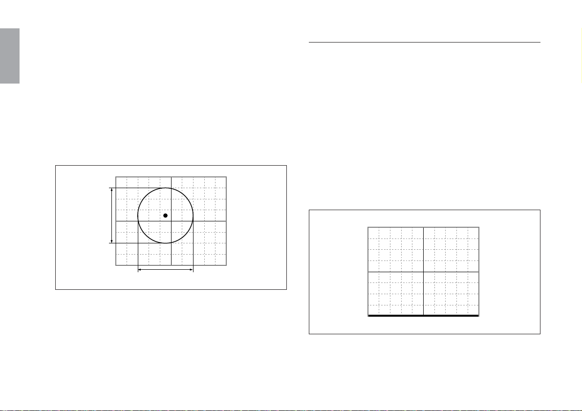
8 SIN/COS信号DCレベルの確認と調整
スケール部またはスライダ部を移動させて全長に渡り
リサージュの中心(図4-4参照)が規定値に入っているこ
とを確認します。
規定値に入っていない場合は、リサージュの中心が規
定値となるようにDCレベルを調整してください。
規定値 リサージュの中心=0.9V±0.02V
DCレベル調整トリマ RV1(SIN) : a方向
RV3(COS) : b方向
a
b
日本語
図4-3.
6 オシロスコープのCH1およびCH2のINPUTCOUPLING
スイッチをDCにします。
7 インターフェースユニットの電源をONにします。
図4-4.
(J
) 27
日本語
9 SIN/COS信号振幅の確認と調整
スケール部またはスライダ部を移動させて全長に渡り
リサージュの振幅A・B(図4-5参照)が規定値に入ってい
ることを確認します。
規定値に入っていない場合は、リサージュの振幅A•B
が規定値となるように振幅を調整してください。
規定値 リサージュの振幅=1.0Vp-p±0.06V
振幅調整トリマ RV2(SIN) : A方向
RV4(COS) : B方向
A
B
図4-5
! インターフェースユニットの電源をOFFにします。
〈3〉原点信号確認
オシロスコープのCH1プローブをインターフェースユニッ
トのチェック端子のTP3とTP4に接続します。
1 オシロスコープのTIME/DIVスイッチを200msにしま
す。
2 オシロスコープのCH1の偏向感度(VOLTS/DIV)を0.2V/
DIVにします。
3 オシロスコープのCH1のINPUTCOUPLINGスイッチを
GNDに合わせ、信号がスクリーン下端にくるようにオ
シロスコープのPOSITIONを調整します。(図4-6参照)
28
図4-6.
(J)
4 オシロスコープのCH1のINPUTCOUPLINGスイッチを
DCにします。
5 インターフェースユニットの電源をONにします。
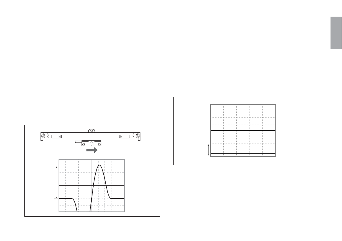
6 原点信号片振幅の確認と調整
スケール部に対してスライダ部を右方向に移動させて
原点を通過させます。
このとき、原点上側の片振幅C(図4-7参照)が規定値に
入っていることを確認します。
規定値に入っていない場合は、原点上側の片振幅Cが規
定値となるように振幅を調整してください。
規定値 原点の片振幅=1.0V±0.04V
原点振幅調整トリマ RV6
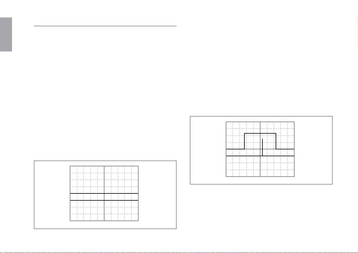
7 原点信号DCレベルの確認と調整
原点のない位置にスケール部またはスライダ部を移動
させます。
このとき、原点信号のDCレベルc(図4-8参照)が規定値
に入っていることを確認します。
規定値に入っていない場合は、原点信号のDCレベルc
が規定値となるようにDCレベルを調整してください。
規定値 原点信号のDCレベル=0.2V±0.02V
原点振幅調整トリマ RV5
日本語
原点検出確認方向
C
図4-7.
c
図4-8.
(J
) 29
日本語
〈4〉原点位置確認
1 インターフェースユニットのチェックランドCL1(ZG)
とチェック端子TP4(GND)に、オシロスコープのCH1
プローブを接続します。
2 インターフェースユニットのコネクタCN2-5ピン(Z)と
チェック端子TP4(GND)に、オシロスコープのCH2プ
ローブを接続します。
3 オシロスコープのTIME/DIVスイッチを200msにしま
す。
4 オシロスコープのCH1、CH2の偏向感度(VOLTS/DIV)
を2V/DIVにします。
5 オシロスコープのCH2のINPUTCOUPLINGスイッチを
GNDに合わせ、CH1はスクリーンセンターにくるよう
にオシロスコープのPOSITIONを調整します。
CH2は、1マス下にくるようにオシロスコープの
POSITIONを調整します。(図4-9参照)
6 オシロスコープのCH1およびCH2のINPUTCOUPLING
スイッチをDCにします。
7 インターフェースユニットの電源をONにします。
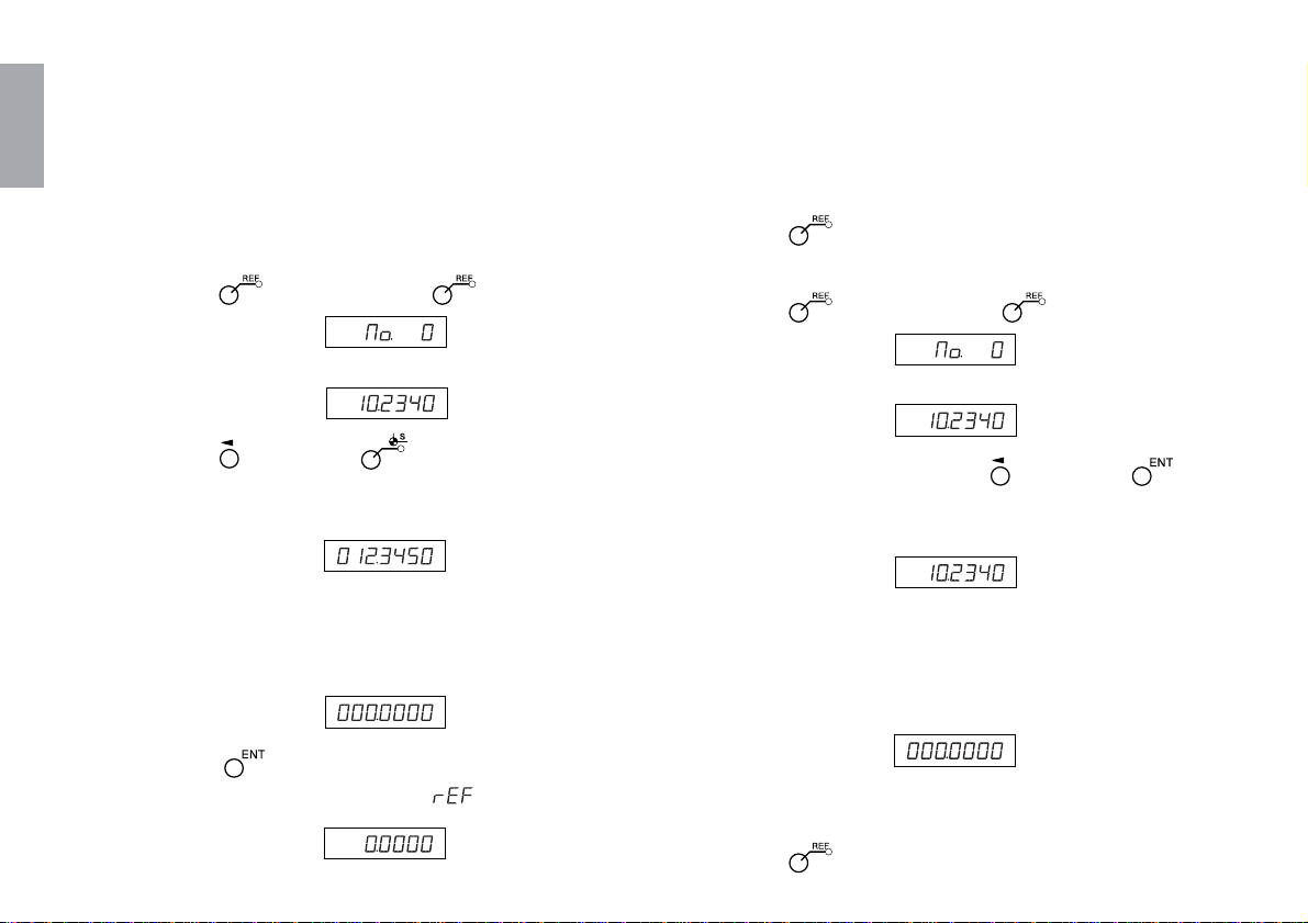
8 原点ゲート信号(CL1)と原点出力信号(CN2-5pin)の位
置設定
スケール部またはスライダ部を移動させて原点を通過
させます。
このとき、原点ゲート信号のセンターに一番近い位置
に原点出力信号が出力されるように、スイッチ1·2(原点
POS1·2sw)を設定してください。(図4-10参照)
CH1 (ZG)
CH2 (Z)
30
(J)
図4-9.
CH1 (ZG)
CH2 (Z)
図4-10.

SIN信号
COS信号
MODE1 MODE2
ON ON
約45°
OFF ON
約135°
ON OFF
約225°
OFF OFF
約315°
原点出力信号は、スイッチ設定で選択した1周期基
準点4つの内1つと原点ゲートの論理積となります。
原点ゲート信号
原点出力
MODEスイッチ1•2共にON時
日本語
(J
) 31
日本語
9 原点動作の確認(LH71を用いて確認する場合)
原点ロードと原点ホールドを用いて、両方向原点の確
認をします。
1. インターフェースユニットを表示ユニットLH71に接
続して電源をONします。
2. 原点オフセット量「000.0000」入力
1)
キーを押します。( ランプ点灯)
5) スケール部またはスライダ部を移動し、原点を通
過させます。
原点を検出したときに「ピッ」と鳴ります。
* 原点を検出すると、カウントが開始されます。
6) キーを押してモードから抜けます。
3. 両方向原点の確認
1)
キーを押します。( ランプ点灯)
32
(J)
表示 ↓
(現在値表示(ABS))
2) キーを押して キーを押します。
保存されているオフセット量(原点ロード時の表
示値)が表示されます。
表示 (例:原点から基準点
までの距離)
3) テンキーでオフセット量(000.0000)を入力しま
す。
表示 (000.0000)
4) キーを押します。
原点待ちになります。(
表示 (点滅)
値点滅)
表示 ↓
(現在値表示(ABS))
2) 原点ホールドする軸の キーを押して キー
を押します。
原点待ちになります。(現在値表示)
表示 (点灯)
3) 2)で原点を通過させた反対方向から原点を通過
すると、原点位置でカウントがホールドしま
す。(軸ラベル点滅)
* 原点を検出したときに「ピッ」と鳴ります。
表示
4) ホールドされた値が「0」であることを確認しま
す。
5) キーを押してモードから抜けます。

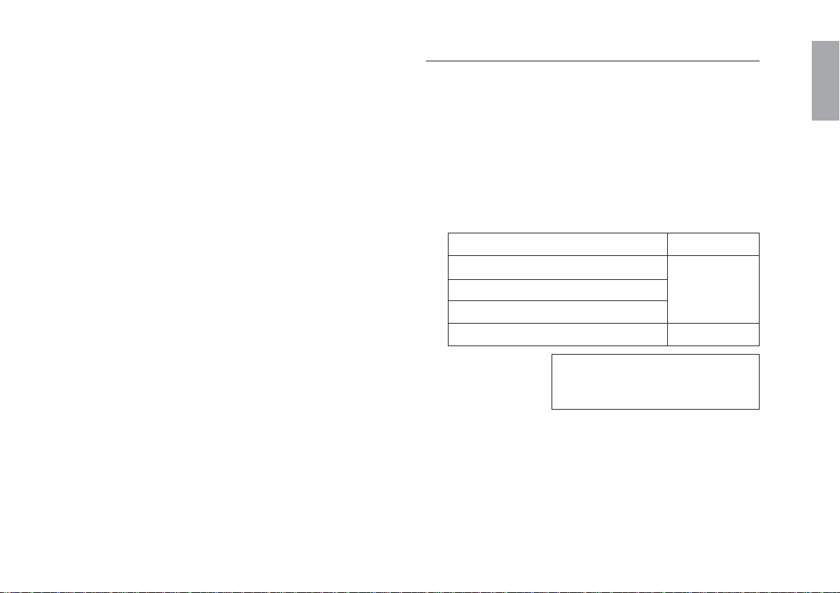
5. 主な仕様
5-1. 一般仕様
スケールユニット
有効長 : 50,100,150,200,250,300,350,400,
450,500,550,600,650,750,850,950,
1050,1250,1400,1600,1850,2050,
2200mm
全長 : 有効長+104mm(有効長200mm以下)
有効長+120mm(有効長250mm以上)
最大可動長 : 有効長+14mm
(有効長200mm以下,左右各7mm)
有効長+30mm
(有効長250mm以上,左右各15mm)
スケール精度 :(5+L)µm(SR138Rシリーズ)
(20℃にて)
Lは有効長(mm)
入出力信号
出力信号 : A/B/Z相
電源 : DC5V±5%
コネクタ : D-sub9ピン
コネクタピン配置 : 外形寸法図参照
分解能 : 0.5µm
5
1000
応答速度
スケール信号 : 60m/min
原点信号 : 60m/min
原点位置 : 有効長の中央1箇所
ケーブル長 :最大30m
許容取付平行度 : 0.1mm
消費電流 :最大200mA
–6
温度膨張係数 : (11±1)×10
使用温度範囲 :0〜40℃
保存温度範囲 : –10〜+50℃
/℃
接続ケーブル
ケーブル長 :3m
製品は一部改良のため、予告なく外観•仕様を変更すること
があります。
日本語
(J
) 33

44
6.5
9.5
6.5
20
10.5
5
25
15
6
21
12 9
25
42
36.5
50
36
60
75
85
(C)
D
(C)
Serial No.
SR138—
* * *
R
* * * * * *
日本語
5-2. 外形寸法図
スケールユニット
取付穴ピッチ×1/2
(有効長L=1050mm以上)
全長=A
取付穴ピッチ=B
有効長=L
中央フットプレート
5×7長穴(取付穴)
アライメントマーク
SerialNo.
34
(J)
有効長マーク
ヘッドケーブル
ケーブル長=300
2-ø5穴,ø9座ぐり
スライダ中心
スライダホルダ
2-4.5×5.5長穴
(取付穴)
丸型コネクタ(オス)
単位:mm

接続ケーブル(CH04:GB-ERシリーズのみに同梱)
44 (91)
ケーブル長
日本語
コンジットケーブル
丸型コネクタ(メス)
インターフェースコネクタ(D-sub9ピンオス)ピン配置
15
69
番号 信号名 備考
1A
2 *A
3B
4 *B
5Z
差動出力
(EIA-422準拠)
最小位相差200ns
6 *Z
70V
8 +5V入力 DC+5V±5%
90V
(86.5)
30
30
インターフェースユニット
**
36
2-M3深さ3
(31) (7)
(17.7)
3820
単位:mm
(J
) 35

日本語
型名
GB-005ER/SR138-005R
GB-010ER/SR138-010R
GB-015ER/SR138-015R
GB-020ER/SR138-020R
GB-025ER/SR138-025R
GB-030ER/SR138-030R
GB-035ER/SR138-035R
GB-040ER/SR138-040R
GB-045ER/SR138-045R
GB-050ER/SR138-050R
GB-055ER/SR138-055R
GB-060ER/SR138-060R
GB-065ER/SR138-065R
GB-075ER/SR138-075R
GB-085ER/SR138-085R
GB-095ER/SR138-095R
GB-105ER/SR138-105R
GB-125ER/SR138-125R
GB-140ER/SR138-140R
GB-160ER/SR138-160R
GB-185ER/SR138-185R
GB-205ER/SR138-205R
GB-220ER/SR138-220R
有効長(L)
50mm
100mm
150mm
200mm
250mm
300mm
350mm
400mm
450mm
500mm
550mm
600mm
650mm
750mm
850mm
950mm
1050mm
1250mm
1400mm
1600mm
1850mm
2050mm
2200mm
全長(A)
有効長+104mm
有効長+120mm
取付穴ピッチ(B)
有効長+91mm
有効長+107mm
C
45.5mm
53.5mm
D
有効長×1/2
50mm
36
(J)

6. トラブルインフォメーション
■ オーバーラン•ケーブル破損•スケールユニットの変形な
どスケールとしての機能に影響を与えるような状況が発
生した場合、修理が必要となります。
• すぐに機械を停止し、ご連絡ください。
■ 損傷の程度によっては、修理不能となります。
このようなトラブル発生を防ぐために、清掃の励行をお願
いします。
• スケールユニットの周りに切粉が溜まらないよう、毎
日始業時と終業時に切粉の清掃をするように心掛けて
ください。
• 切粉が溜まるとスケールユニットの摺動を妨げ、障害
の原因となることがあります。
• 切粉の清掃にはエアーガン等の使用はお避けくださ
い。スケールユニットの走行部分はシールされていま
すが、構造上完全密閉にはなっておりません。エアー
ガン等を使用すると、切粉等がスケールユニットの
シール部分から侵入し、故障の原因となることがあり
ます。
日本語
(J
) 37

38
(J)

■ General precautions
When using Magnescale Co., Ltd. products, observe the following
general precautions along with those given specifically in this
manual to ensure proper use of the products.
• Before and during operations, be sure to check that our products
function properly.
• Provide adequate safety measures to prevent damage in case
our products should develop a malfunction.
• Use outside indicated specifications or purposes and
modification of our products will void any warranty of the
functions and performance as specified for our products.
• When using our products in combination with other equipment,
the functions and performance as noted in this manual may not
be attained, depending upon the operating environmental
conditions. Make a thorough study of the compatibility in
advance.
■ Precautions for use under the following
environments
1 When using water-miscible cutting fluid or when cutting metal or
non-metal (ceramic, glass fiber, etc.) objects.
• Mount the scale unit so that it is not directly exposed to
water-miscible cutting fluid or cutting scraps.
• Attach a scale cover to prevent water-miscible cutting fluid
mist or powder from entering the inside of the scale unit.
2 When mounted on a honing machine or other machine that
slides at high speed for long periods within a specific area.
• Regularly apply oil or spray lubricant (CRC•WD40, etc.).
If using in the environments in 1 or 2, be sure to always implement
the measures above. Quality cannot be guaranteed unless these
measures are implemented.
(E
) i
Safety Precautions
Magnescale Co., Ltd. products are designed in full consideration of safety. However, improper
handling during operation or installation is dangerous and may lead to fire, electric shock or other
accidents resulting in serious injury or death. In addition, these actions may also worsen machine
performance.
Therefore, be sure to observe the following safety precautions in order to prevent these types of
accidents, and to read these “Safety Precautions” before operating, installing, maintaining,
inspecting, repairing or otherwise working on this unit.
Warning indication meanings
The following indications are used throughout this manual, and their
contents should be understood before reading the text.
Warning
Failure to observe these precautions may lead to fire, electric shock
or other accidents resulting in serious injury or death.
Symbols requiring attention
CAUTION ELECTRICAL
SHOCK
Symbols prohibiting actions
Caution
Failure to observe these precautions may lead to electric shock or
other accidents resulting in injury or damage to surrounding objects.
DO NOT
DISASSEMBLE
Symbols specifying actions
Note
This indicates precautions which should be observed to ensure
ii
(E)
proper handling of the equipment.
UNPLUGGING

Warning
Caution
• Do not use this unit with voltages other than the specified supply voltage as this may
result in fire or electric shock.
• Do not perform installation work with wet hands as this may result in electric shock.
• Do not disassemble or modify the unit as this may result in injury or damage the
internal circuits.
• Be sure to check the machine and device conditions to ensure work safety before
working on the machine.
• Be sure to cut off the power supply, air and other sources of drive power before
working on the machine. Failure to do so may result in fire or accidents.
• When turning on the power supply, etc. to operate the machine, take care not to catch
your fingers in peripheral machines and devices.
(E
) iii
Handling Precautions
Installation precautions
When installing this unit, care should be given to the following points to prevent noise
and electromagnetic wave interference from other equipment.
1. Do not pass lead and connection cables through the same ducts as power lines.
2. Be sure to install the unit at least 0.5 m/19.6" or more away from high voltage or
large current sources or high-power relays.
3. Absolutely do not bring the unit near magnets or sources of electromagnetic waves.
Note
• Magnet chucks and other sources of magnetic force of approx. 6 × 10⁻² [T] should
be kept at least 50 mm/19.6" or more away from the side surfaces and 10 mm/
0.39" or more away from the opening surfaces of the steel chassis on the scale
unit.
• If the unit must be installed close to sources of magnetic force, be sure to
implement adequate electromagnetic shielding countermeasures.
4. Be sure to ground the scale part and the slider part to prevent trouble to noise.
iv
(E)

Installation place precautions
1. Mount the scale unit for more precise positioning as closely as possible to the
workpiece or to the object being measured.
(The farther the scale unit is mounted from workpiece, the greater the mechanical
errors grow.)
2. The scale unit should be used within an ambient temperature range of 0 to 40°C
(32 to 104°F). Avoid locations where the scale unit is exposed to direct sunlight and
heat sources such as motors.
3. Do not place anything on the mounted scale unit, or step on it: excessive force to the
scale unit causes trouble.
(E
) v

vi
(E)

Contents
1. Outline ......................................................................... 2
1-1. Introduction .................................................................. 2
1-1-1. SR138R series ...................................................... 2
1-1-2. CH04 series .......................................................... 2
1-1-3. GB-ER series ........................................................ 2
1-1-4. CE10 series ........................................................... 2
1-2. Major Features ............................................................. 2
1-3. Parts Configuration ...................................................... 3
1-4. System Configuration .................................................. 3
2. Name and Function of Each Part ............................. 5
2-1. Scale Unit ..................................................................... 5
2-2. Connection Cable ......................................................... 7
3. Mounting Method .......................................................8
3-1. Precautions before Mounting ...................................... 8
3-2. Mounting Precautions .................................................. 9
3-2-1. Checking the mounting method ........................... 9
3-2-2. Setting the movement range............................... 10
3-2-3. Protection of the head cable ............................... 10
3-2-4. Mounting a protective cover .............................. 10
3-3. Required Items for Mounting .................................... 11
3-4. Mounting Dimensions ............................................... 12
<1> When the mounting surface already meets
parallelism and flatness requirements ...... 12
<2> When the scale mounting surface
is a casting surface ................................... 13
<3> Mounting the slider part ................................. 15
<4> Removal of the slider holder ......................... 18
<5> Checking the movement range ..................... 18
<6> Mounting the headcable ................................ 18
<7> Connecting cables .........................................19
<8> Mounting the conduit cable ........................... 21
<9> Mounting the round connectors ..................... 22
<10> Connecting the interface unit to a
counter unit ............................................... 23
<11> Connecting the interface unit to a controller .... 24
<12> Removal of the scale unit ..............................24
4. Electrical Adjustment of the Connection
Cable Circuit ............................................................. 25
<1> Removing the upper case ............................. 25
<2> SIN/COS signal check ...................................26
<3> Reference point signal check ........................ 28
<4> Reference point position check ..................... 30
5. Specifications........................................................... 33
5-1. General Specifications ............................................... 33
5-2. Dimensions ................................................................. 34
6. Trouble Information ................................................. 37
(E
English
) 1

1. Outline
English
1-1. Introduction
1-1-1. SR138R series
The SR138R series is a linear scale with a built-in reference
point.
The relative positional relationship between the scale part and
slider part is adjusted and secured using a slider holder.
Be sure to always use together with the CH04 connection cable
(optional).
Note
If the SR138R series and CH04 are ordered separately, electrical
adjustment needs to be made for the CH04 before usage. No
adjustment is necessary if electrical adjustment was requested
when ordering.
1-1-2. CH04 series
This is a dedicated cable incorporating a built-in circuit for
converting SR138R series signals to general-purpose A/B
quadrature output. Combining with the SR138R series enables
connection of Magnescale Co., Ltd. counter units (such as the
LH70 and LH71), controllers, and other external equipment.
1-1-3. GB-ER series
The GB-ER series is a product that includes the SR138R series
and a CH04-03C connection cable which has already been
electrically adjusted.
Note
Be sure that the serial No. of the SR138R series and the
combination No. of the CH04-03C match when using in
combination together.
1-1-4. CE10 series
This is an extension cable (optional) for extending the cable
length.
Combining with the CH04 enables extension up to a maximum of
30 m/98.4 ft.
1-2. Major Features
• Compact size and light weight, built-in reference point
• Easy to install
• Same coefficient of expansion as that of machine tools
• Highly accurate position detection
• Highly resistant to oils and dirt
2
(E)

1-3. Parts Configuration
1-4. System Configuration
Scale unit.......................................................................... 1
Connection cable (CH04: included only with the GB-ER series) ....
Accessories
Clamp ............................................ 1
Cable clamps ....... (small 2, large 4)
Spacers ......................................... 5
Screening label ............................. 1
Plain washers (S) .......................... 2
Plain washers (M) ......................... 3
+B4×10 .......................................... 2
+P4×5 ............................................ 4
+P4×10 .......................................... 4
+K3×5 ............................................ 2
HSB M4×8 ..................................... 2
HSB M4×10 ................................... 3
HSB M4×12 ................................... 2
HSB M5×25 ................................... 2
Nuts (M5) ...................................... 2
Fixing plate .................................... 1
System connections
• SR138R series
Scale unit
1
• GB-ER Series
Scale unit (SR138R)
Extension cable
(optional)
Connection cable
(CH04-03C)
Connection cable
(optional)
Counter unit
(optional)
CH01-**C
COMBINATION No.
******
MADE IN JAPAN
Counter unit
LH70/71 series etc.,
Controller
(optional)
(E
English
) 3
Model lineup (SR138R series) Model lineup (GB-ER series)
English
Model name
SR138-005R
SR138-010R
SR138-015R
SR138-020R
SR138-025R
SR138-030R
SR138-035R
SR138-040R
SR138-045R
SR138-050R
SR138-055R
SR138-060R
SR138-065R
SR138-075R
SR138-085R
SR138-095R
SR138-105R
SR138-125R
SR138-140R
SR138-160R
SR138-185R
SR138-205R
SR138-220R
Measureing
length (L)
50 mm/1.9"
100 mm/3.9"
150 mm/5.9"
200 mm/7.8"
250 mm/9.8"
300 mm/11.8"
350 mm/13.7"
400 mm/15.7"
450 mm/17.7"
500 mm/19.6"
550 mm/21.6"
600 mm/23.6"
650 mm/25.5"
750 mm/29.5"
850 mm/33.4"
950 mm/37.4"
1050 mm/41.3"
1250 mm/49.2"
1400 mm/55.1"
1600 mm/62.9"
1850 mm/72.8"
2050 mm/80.7"
2200 mm/88.6"
Center
foot
None
Included
Model name Center
GB-005ER
GB-010ER
GB-015ER
GB-020ER
GB-025ER
GB-030ER
GB-035ER
GB-040ER
GB-045ER
GB-050ER
GB-055ER
GB-060ER
GB-065ER
GB-075ER
GB-085ER
GB-095ER
GB-105ER
GB-125ER
GB-140ER
GB-160ER
GB-185ER
GB-205ER
GB-220ER
SR138-005R
SR138-010R
SR138-015R
SR138-020R
SR138-025R
SR138-030R
SR138-035R
SR138-040R
SR138-045R
SR138-050R
SR138-055R
SR138-060R
SR138-065R
SR138-075R
SR138-085R
SR138-095R
SR138-105R
SR138-125R
SR138-140R
SR138-160R
SR138-185R
SR138-205R
SR138-220R
Measureing
length (L)
50 mm/1.9"
100 mm/3.9"
150 mm/5.9"
200 mm/7.8"
250 mm/9.8"
300 mm/11.8"
350 mm/13.7"
400 mm/15.7"
450 mm/17.7"
500 mm/19.6"
550 mm/21.6"
600 mm/23.6"
650 mm/25.5"
750 mm/29.5"
850 mm/33.4"
950 mm/37.4"
1050 mm/41.3"
1250 mm/49.2"
1400 mm/55.1"
1600 mm/62.9"
1850 mm/72.8"
2050 mm/80.7"
2200 mm/88.6"
foot
None
Included
Connection cable
length model
CH04-03C
Cable
length
3 m/9.8 ft
4
(E)
7
2. Name and Function of Each Part
2-1. Scale Unit
Center foot plate securing hole
Side cover L
Scale part
Slider part
Measuring length mark (left)
Model name
6
SR138−***R
Slider
1
Slider holder
Head cable
5
3
Reference point mark
Slider mounting hole (two holes)
1 Slider
This holds the detection head. When shipped, it is secured by
the slider holder.
Alignment mark
4
2
Slider mounting hole (two holes)
Slider center
Center foot plate
Measuring length mark (right)
3
Serial No./Reference
point indication
8
Serial No.
******
Scale unit
Round connector (male)
Scale
mounting hole
(two holes,
both ends)
Side cover R
2 Slider center
This indicates the mechanical center of the slider. It serves as
a reference when viewing the relative position with the
measuring length marks.
(E
English
) 5

English
3 Measuring length marks
These indicate the effective movement range over which
accuracy is assured with respect to the slider center. The
measuring length represents the length of the effective
movement range.
Note
When mounting and using the scale unit, be sure to operate
the unit within this range. Using the scale unit in excess of
the effective movement range may damage the unit.
4 Reference point mark
This mark indicates the position where the reference point
signal is output with respect to the slider center.
In the standard specifications, one reference point exists in
the center of the measuring length.
5 Slider holder
This secures the scale part and slider part, and should be
stored after removal.
6 Model name
This indicates the scale unit model name.
7 Center foot plate
This is mounted when the measuring length is 1050 mm/
41.3" or more, and should be secured when mounting the
scale unit.
8 Serial No./Reference point indication
This indicates the scale unit serial No. and the reference
point of the scale unit.
For the GB-ER series, it is the same as the combination No.
of the matching connection cable.
Note
In this scale system, the serial No. of the scale unit and the
combination No. of the connection cable (CH04 series) must
match when used in combination together.
6
(E)

1
2-2. Connection Cable
CH04 : included only with the GB-ER series
Note
When procured separately, electrical adjustment is necessary.
Input/output connector
Interface unit
5
6
Model name
3
7
CH04-03C
Combination No.
Status lamp
1 Interface unit
This is connected to the rear panel of the counter unit.
The interface unit incorporates circuits that have been
electrically adjusted to the optical setting.
2 Conduit cable
This protects the internal cables.
3 Model name
This indicates the cable model name.
4 Round connector (female)
This connects with the round connector (male) on the scale
unit.
5 Input/output connector
Scale signals and reference point signals are output when
DC +5 V is supplied as the power source.
Conduit cable
2
8
Interface unit tap for fixing
Round connector
4
(female)
6 Combination No.
For the GB-ER series, this is the same as the serial No. of the
matching scale unit.
7 Status lamp
This is a lamp for checking the signals.
Lit green : Normal
Lit red : Error (Overspeed, cable disconnection, invalid
signal)
8 Interface unit tap for fixing
The interface unit can be secured in place using the supplied
fixing plate and screw. (M3 depth 3 mm)
(E
English
) 7

3. Mounting Method
English
3-1. Precautions before Mounting
Before mounting, be sure to always check “Mounting
Precautions”.
Disassembly prohibited
<Scale unit>
• Do not disassemble the scale unit. The accuracy cannot be
guaranteed if disassembled. The slider holder only can be
removed.
<Connection cable>
• The connection cable is already adjusted, and so do not
disassemble it. The accuracy cannot be guaranteed if
disassembled.
• The connection cable that is sold separately for the SR138R
must have its case removed for electrical adjustment. It should
not be disassembled for any other reason.
Do not apply excessive force.
• During operation, do not apply excessive force to the scale
unit. The scale unit is comprised of precision mechanical parts
and electromagnetic parts. Applying excessive force can
significantly reduce the performance and lifespan.
• During operation, do not apply excessive force to the interface
unit of the connection cable. Precision electrical parts are
installed and adjusted inside the interface unit. Applying
excessive force can significantly reduce the performance and
lifespan.
• When carrying, support both the scale part and slider part
together. Do not carry by holding the head cable, round
connectors, or other parts.
8
(E)

3-2. Mounting Precautions
Note
Be sure to ground the scale unit and the slider part to prevent
trouble to noise.
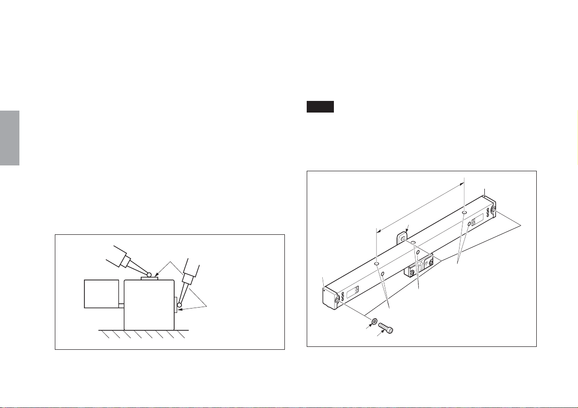
When mounting the scale unit vertically, be sure to mount the
slider part of the scale unit on the opposite side of a workpiece or
cutting tool.
3-2-1. Checking the mounting method
Check that the scale unit can be mounted in the relative position
shown in the Fig. 3-1.
* Do not mount the scale in any other direction since difficulties
with servicing and maintenance may arise.
(The mounting position A in particular is recommended:
cutting fluid and chips may be effectively kept out.)
(The mounting position B is possible only when cutting fluid
and chips will not get inside the scale.)
Recommended
A
Fig. 3-1 Scale unit mounting direction
B
Cutting tool
Fig. 3-2 Mounting the scale unit vertically
Slider part
Scale part
(E
English
) 9

3-2-2. Setting the movement range
3-2-3. Protection of the head cable
English
Mount the scale unit in the operating range shown in Fig. 3-3.
• A leeway (equivalent to 7 mm/0.28" at the left and right ends of
the scale unit for a measuring length of up to 200 mm/7.8" and
15 mm/0.59" for a measuring length of up to 250 mm/9.8") is
provided for the slider movement. Be sure not to move the
slider part beyond this limit or the scale part may be damaged.
• Mechanical limiting devices (stoppers, etc.) are required for
sliders which move in excess of the effective movement range
of the scale unit. In these cases, be sure to take the appropriate
measures before mounting the scale unit.
Measuring
length mark
Slider center
Mount the scale so that the slider center moves within this range.
(Effective movement range)
Fig. 3-3 Movement range
Measuring
length mark
The head cable has an integrated design with the scale unit, and
so mount the scale unit while being careful not to put pressure on
the cable. Take care not to pull the head cable forcefully or bend
it repeatedly or the cable may break.
3-2-4. Mounting a protective cover
Where the scale unit is exposed to chips and cutting fluid, provide
a protective cover shown in Fig. 3-4 to maintain high
performance of the scale unit.
Fig. 3-4 Example of protective cover
10
(E)

3-3. Required Items for Mounting
Accessories (supplied)
Hexagonal socket head cap screw ............................................ 3
M4×10 for mounting scale part
(2 pcs. for scale of L<1000 mm/39")
Hexagonal socket head cap screw
M4×8 for mounting slider part ...................................... 2
M4×12 for mounting slider part .................................... 2
Pan head screw
M4×5 for cable clamp (small) ....................................... 2
M4×10 for cable clamp (large) ...................................... 4
M4×5 for mounting interface unit ................................. 2
M3×5 for mounting fixing plate .................................... 2
Plain washer (M) ...................................................................... 3
with 4 mm dia. hole for mounting scale part
(2 pcs. for scale of L<1000 mm/39")
Plain washer (S) ........................................................................ 2
with 4 mm dia. hole for mounting slider part
Cable clamp for mounting conduit cable (large) ..................... 4
Screening label ......................................................................... 1
for concealing the screw holes after the slider holder
has been removed
Hexagonal socket head cap screw ............................................ 2
M5×25 for mounting slider part
Hexagonal nut ........................................................................... 2
M5 for mounting slider part
Spacer ....................................................................................... 5
t=0.1 for mounting slider part
Clamp for mounting round connectors .................................... 1
Binding pan head screw
M4×10 for mounting clamp........................................... 2
Cable clamp for securing head cable (small)........................... 2
Fixing plate for securing interface unit .................................... 1
Tools you need other than the supplied accessories.
Bracket for mounting scale part (for A, B surfaces) ........... 1 to 2
Bracket for mounting slider part (for C surface) ....................... 1
0.01 mm/0.0005" pick tester (or dial gauge) ....................... 1 to 2
Allen wrench for M2.6 (2 mm/0.07") type ................................ 1
Allen wrench for M4 (3 mm/0.11") type.................................... 1
Allen wrench for M5 (4 mm/0.15") type.................................... 1
Tap M4 ........................................................................................ 1
Drill ø3.2/0.126" dia ................................................................... 1
Electrical drill.............................................................................. 1
Liner, spacer t=0.05 to 0.2 mm/0.002 to 0.008" ................. Some
Phillips head screwdriver for M2.6 ............................................ 1
Adjustable spanner (small) ......................................................... 2
Note: L= measuring length
t= thickness
(E
English
) 11

English
3-4. Mounting Dimensions
0.1 MG
0.1
25/0.98"
12/0.47" 25/0.98" 25/0.98"
0.1 MG
0.1
0.1 MG
Fig. 3-5 Mounting dimensions
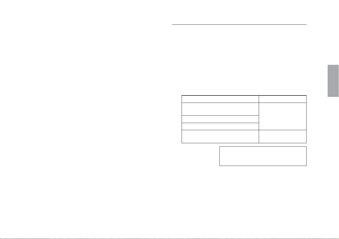
<1> When the mounting surface already meets
parallelism and flatness requirements
When the scale mounting surface is finished and meets the
parallelism and flatness specifications below, just mount the
scale part.
Scale unit with measuring length of less than 1050 mm/
41.3" (no center foot plate)
Screws used / Tightening torque: Hexagonal socket head cap
screws M4×10 (2 pcs.), 2 plain washers (M) / 350 N·cm
8/0.31" or more
A
B
D
C
Scale unit with measuring length of 1050 mm/41.3" or
more (with center foot plate)
Screws used / Tightening torque: Hexagonal socket head cap
screws M4×10 (3 pcs.), 3 plain washers (M) / 350 N·cm
Flatness of A, B surfaces
Parallelism of A, B surfaces to
machine table movement
Side A: Scale part abutment side
Side B: Scale part installation side
within 0.1 mm/0.004"
Provide the range shown in Fig. 3-5 for surface A. The above
tolerances suppose no quick change in the surfaces and no
obstacle in the way between the right and left mounting surfaces.
12
(E)
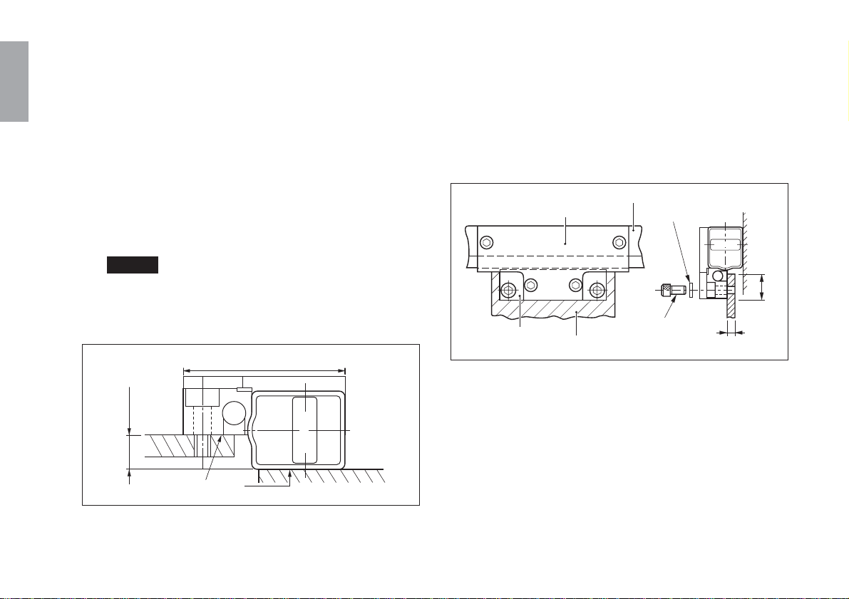
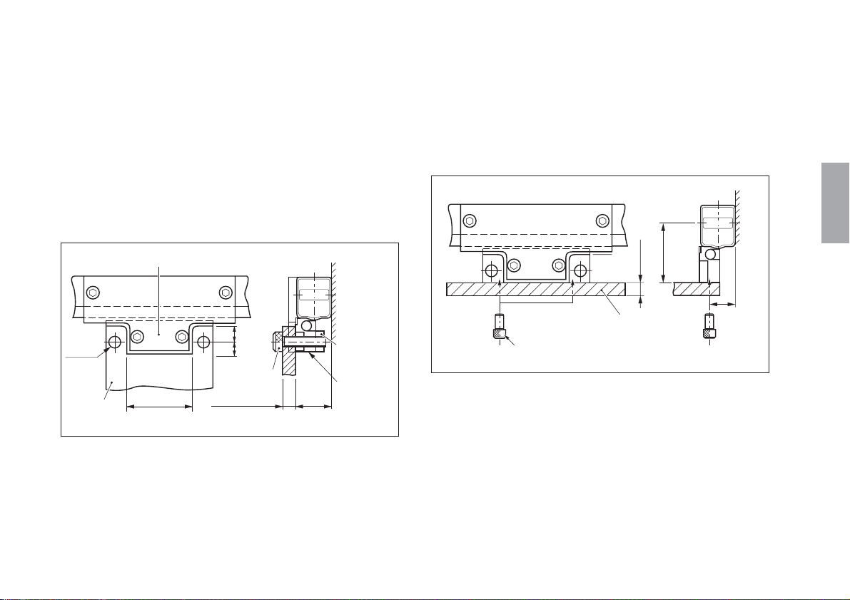
<2> When the scale mounting surface is a
casting surface
Mount the scale part using mounting brackets
(1) When the scale mounting surface is a casting
surface and parallelism is not satisfied
Use mounting brackets and adjust so that the parallelism
specified in <1> may be satisfied.
The mounting brackets need only cover the length of at least
the feet of the scale part. However, the brackets must be long
enough for the parallelism of the right and left feet of the
scale part to be measurable.
If a problem occurs in the temperature tracking performance
with the machine, try to place the mounting brackets over the
entire length of the scale unit.
Parallelism measurement of side A
Mounting bracket
Pick tester
Parallelism measurement of side B
English
Fig. 3-6 Parallelism measurement of the mounting brackets
If the mounting bracket shape has an abutment surface,
adjust it so that the surface accuracy reading is within the
range shown in Section <1>. Use the procedure in (4) to
make adjustments if there is no abutment surface. Also, use
the procedure in (4) when the installation surface accuracy
cannot be obtained.
(E
) 13
English
(2) Checking of mounting position and tapping
Check that the parallelism for mounting scale part meets the
specifications, and then tap for M4 screws of 10 mm/0.39"
depth referring to the outline drawing on page 34.
(3) Mounting of scale part
Mount the scale part loosely with M4×10 hexagonal socket
head cap screws and plain washers (large), and leave it for 30
minutes for the scale part to reach ambient temperature.
Then firmly mount the scale.
(4) Measuring parallelism of scale part with machine
table movement
Place a pick tester or dial gauge directly where the alignment
mark (Fig. 3-7 1) is positioned on the side of the scale part,
and check that the scale part is surely mounted parallel to the
machine table movement.
Adjust the parallelism of the length between the two alignment
marks to within 0.08 mm/0.003" and tighten the setscrews. For
the scale with a measuring length of 1050 mm/41.3" or more,
adjust the parallelisms of the lengths between the alignment mark
and those on both sides of it to within 0.08 mm/0.003".
Note
Since alignment marks are not provided on scales part with a
measuring length of 150 mm/5.9" or less, place the pick tester or
dial gauge on the scale part and ensure that the allowance at the
two ends of the machine travel is within 0.08 mm/0.003".
Foot
Parallelness allowance
within 0.08 mm/0.003"
Center foot plate
14
2
Fig. 3-7 Parallelness check of scale part and machine table movement
1
Alignment mark
(E)
Foot
Alignment marks
Alignment marks
Plain washer
(M)
M4×10
Fig. 3-8 Parallelism check by alignment marks
Alignment marks
(5) When the specified parallelism for the scale
mounting bracket is not obtained
Insert spacers below the feet and make adjustment by
placing a pick tester or dial gauge at 2 in Fig. 3-7 to adjust
the parallelism to within 0.08 mm/0.03" throughout the
length between may be obtained at the alignment marks.
For the scale unit with a measuring length of more than
1050 mm/41.3", make sure that the parallelism near the
center foot plate is also within 0.08 mm/0.003".
<3> Mounting the slider part
(1) When parallelism and flatness of the mounting
surface are already satisfied
When the mounting surface is finished and its parallelism
and flatness satisfy the specifications below, just mount the
slider part.
Screws used / Washers used: Hexagonal socket head cap
screws M4×12 (2 pcs.), 2 plain washers (S)
Tightening torque: 350 N·cm
Flatness of C and D surface
Parallelism of C and D surface to
machine table movement
Parallelism between B and C surfaces
Parallelism between B and D surfaces
Clearance between B and C surface
Side A : Scale part abutment surface
Side B : Scale part installation surface
Side C, D : Slider part installation surface
Move the machine table till the mounting surface comes just at
the slider part.
First use the supplied spacers to fill the gap between the
mounting surface and slider part, and then secure the slider part.
Then remove the screws which fix slider holder. In this process,
be careful not to make the slider part and the mounting bracket
contact with each other.
within 0.05 mm/0.02"
within
0.05 mm/60mm
(0.002"/2.36")
8.7 to 8.8 mm/
0.343 to 0.346"
(E
English
) 15
English
[When the supplied spacers (t=0.1 mm×5) are
unable to fill the gaps between the mounting
surface and the slider part]
Loosen the screws securing the slider part of the slider
holder, press the slider part against the scale part, and tighten
the bolts in this condition.
(2) When the gap between the B and C surfaces is set
to exactly 9 mm/0.35"
Loosen the screws securing the slider holder and move the
slider part by hand to align it with the brackets. Then secure
the slider part at the position of 42±0.2 mm/1.65"±0.008" as
shown in Fig. 3-9. Spacers are not required.
Note
Do not attempt to move the bracket side with the slider
holder secured, as the brackets may strike the slider part.
42±0.2/1.65"±0.008"
8.7 to 8.8/0.34" to 0.35"
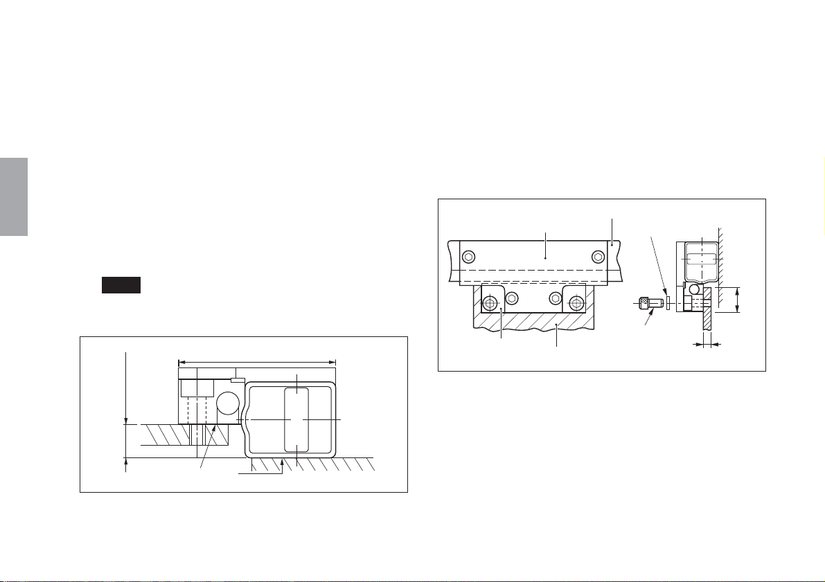
(3) When the slider mounting surface has yet to meet
the specifications
When the mounting surface of the machine is a casting
surface, use a bracket.
Place the bracket on the underside of the slider part without
loosening the screws that hold the slider holder. Adjust the
position of the bracket and mount it with the supplied
M4×12 bolts.
Slider part
Slider holder
Scale part
Mounting bracket
Fig. 3-10
2-Plain washers
(small)
2-M4×12
(accessory)
4t to 6t/0.16" to 0.24"
17/0.67" or less
16
(E)
B
C
Fig. 3-9
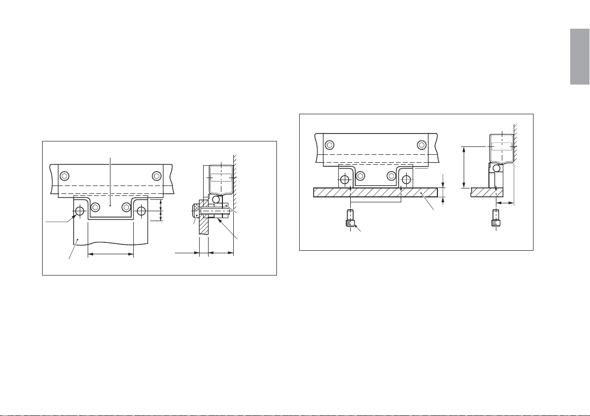
(4) When the bracket is mounted on the top of the
slider part
Align the mounting bracket with the top surface of the slider
part, and adjust the bracket so that the height from the scale
mounting surface is brought to 21±0.1mm/0.83"±0.004".
Ensure that the mounting bracket used comes in a shape that
accommodates the projecting part of the slider holder. As
shown in Fig. 3-11, secure the slider part using two cap
screws (M5×25 hexagonal socket head cap screws) and two
nuts (M5).
Projecting part of the slider
(5) When the bracket is mounted on the rear of the
slider part
Align the slider part rear side and mounting bracket without
loosening the screw securing the slider holder, and then
secure using the supplied two screws M4×8 while adjusting
the bracket height.
42±0.2
4t/0.16"
1.65"±0.008"
English
2-ø5.5
ø0.22"
Mounting
bracket
37/1.46"
9
0.35"
7
0.27"
2-M5×25
(accessory)
6 to 8t
0.24" to 0.31"t
Fig. 3-11
21±0.1
0.83"±0.004"
2-M5 nuts
(accessory)
Slider part
Mounting bracket
15/0.59"
2-M4×8 (accessory)
Fig. 3-12
*The effective screw depth of the slider part is 4.5 mm.
If the mounting bracket has a thickness less than 4 mm,
use washers to adjust the thickness.
(E
) 17
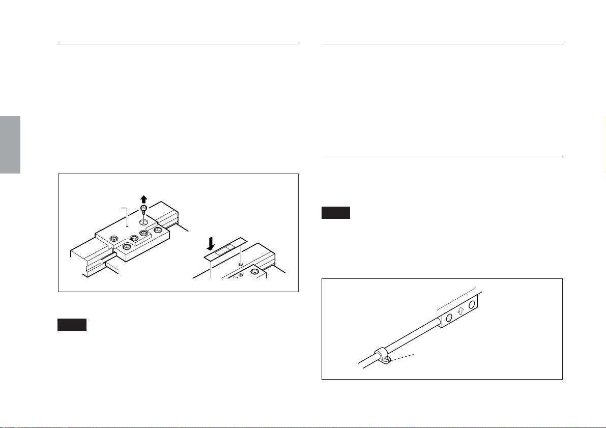
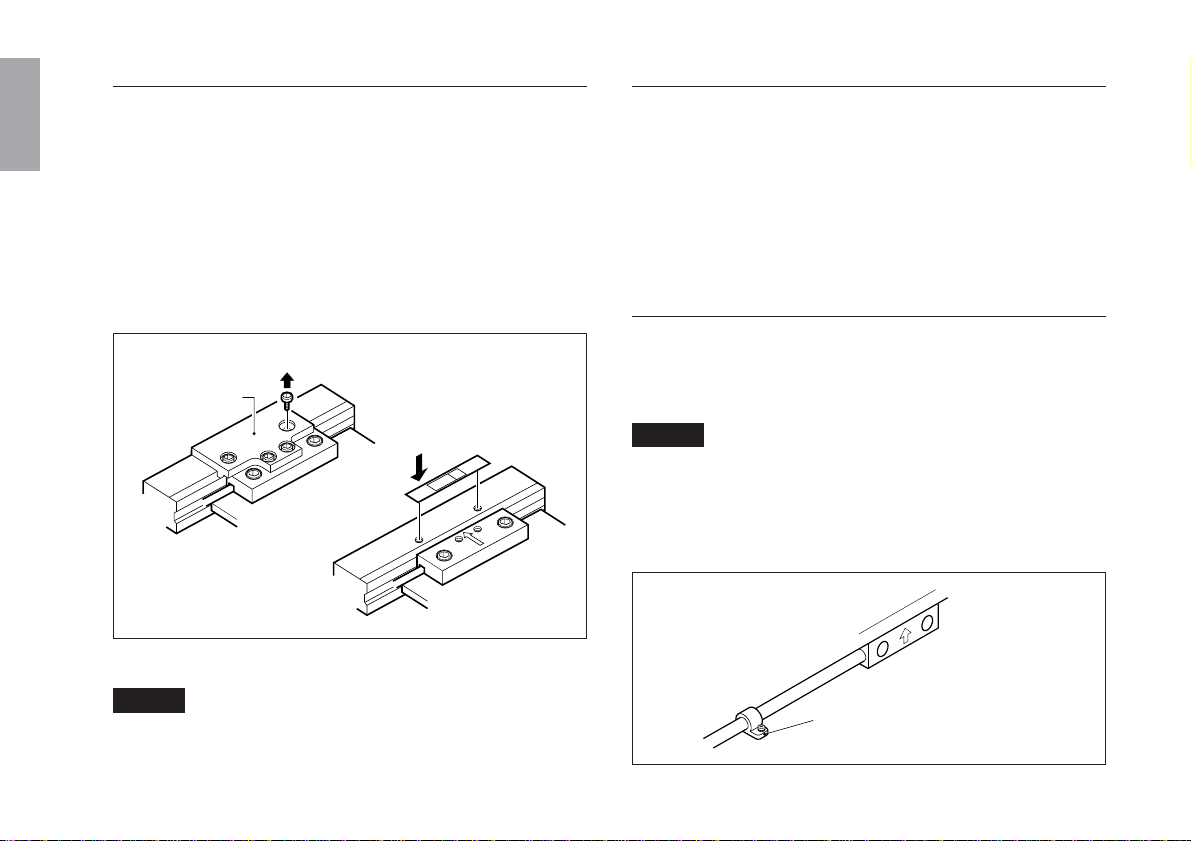
<4> Removal of the slider holder
<5> Checking the movement range
English
Remove the four M2.6 mounting screws for the slider holder and
then remove the slider holder itself.
• Be sure to adhere the screening label (accessory) to cover the
screw holes after removing the slider holder. If these holes are
not plugged, chips, cutting fluid or dust may enter and the
accuracy of the scale may be deteriorated. Use a ball-point pen
to enter the mounting date and name of the person responsible
on the label.
Remove the four M2.6 screws.
Slider holder
Adhere the screening label
(accessory).
Fig. 3-13 Removal of slider holder
Note
Keep slider holder and four M2.6 screws after the installation.
After mounting the scale part and slider part, be sure to move the
machine over the overall length of the scale to check that the
machine moves within the measuring length.
Remember that the scale unit may be damaged if the machine
moves beyond the movable range of the scale unit (measuring
length + leeway).
<6> Mounting the headcable
Fix the head cable with cable clamps so that they will not
interfere with moving parts of the machine.
Note
The head cable has an integrated design with the scale unit, and
so mount the scale unit while being careful not to put pressure on
the cable. Take care not to pull the head cable forcefully or bend
it repeatedly or the cable may break.
Secure the cable clamp using a M4×5
cable clamp screw (accessory).
18
(E)
Fig. 3-14
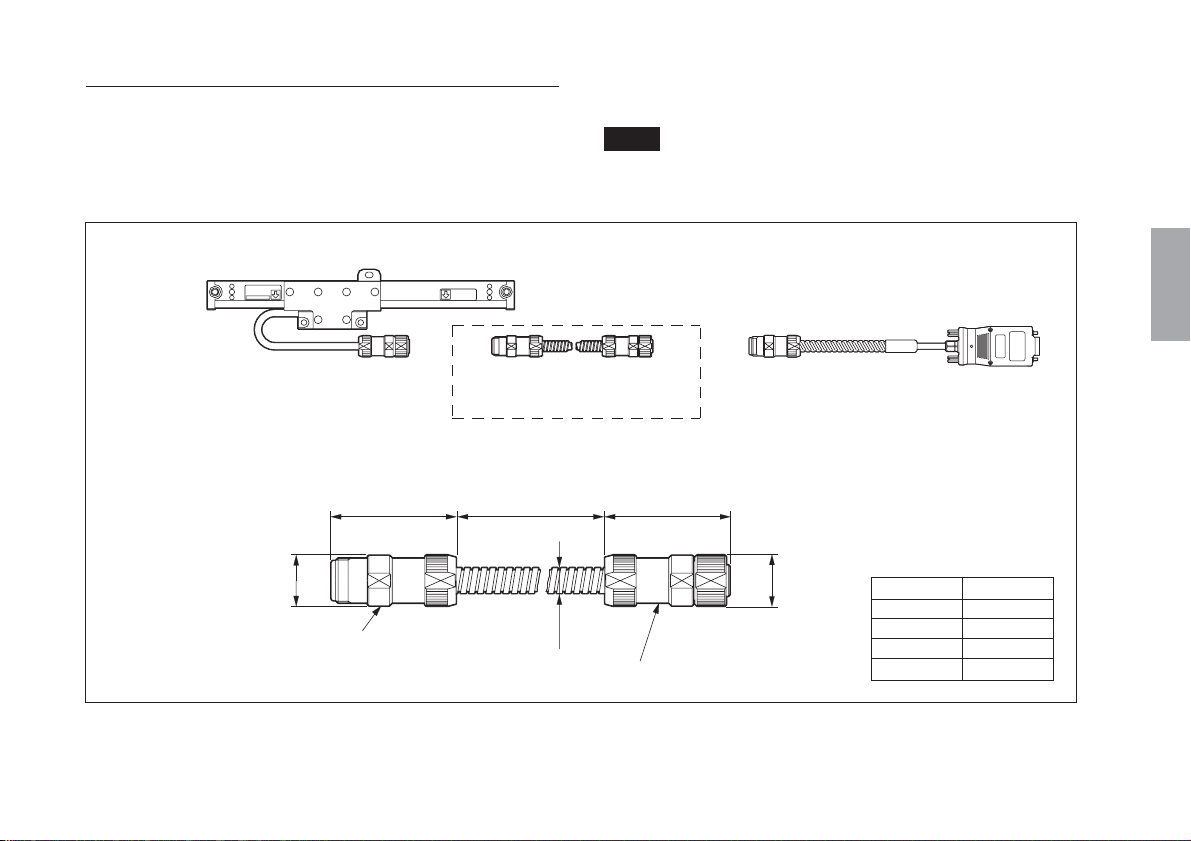
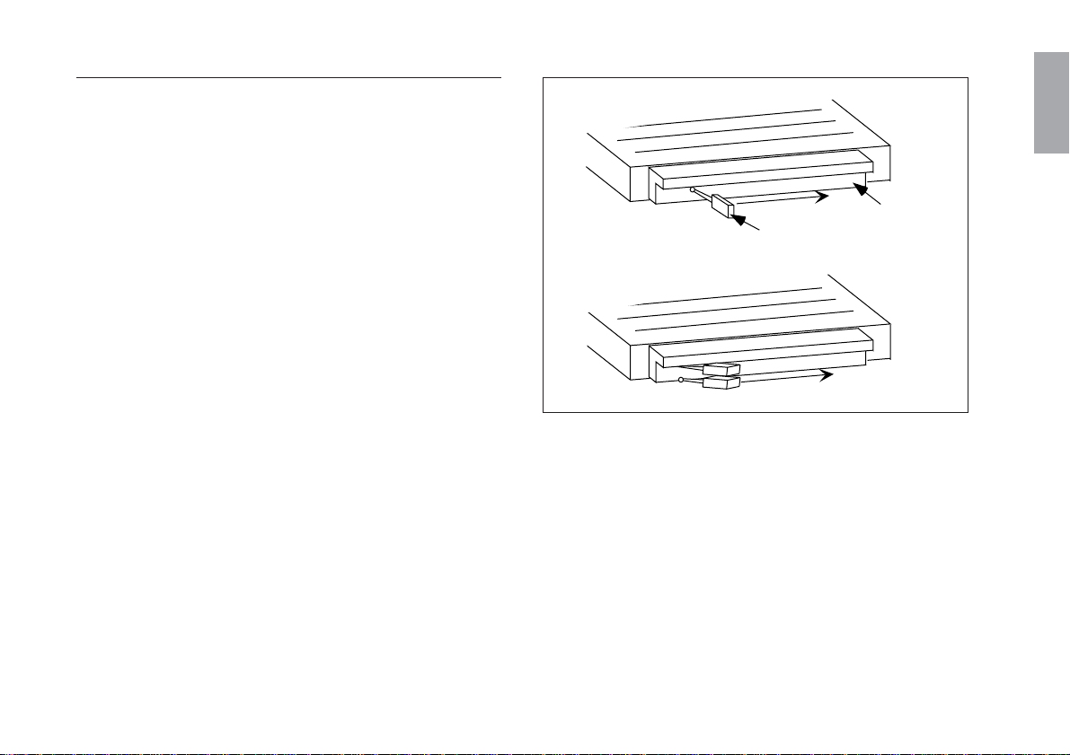
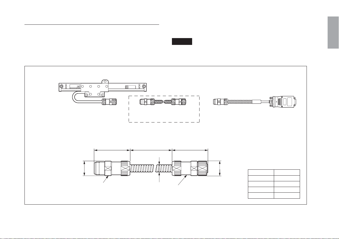
<7> Connecting cables
The distance between the SR138R and GB-ER series and the
connection cable can be extended by using an optional extension
cable (CE10 series).
Scale unit
Extension cable (CE10-**C)
Cable length
CE10-**C
44/1.73" 44/1.73"
ø18
ø0.70"
Round connector (female)
Note
The maximum total cable length when extended is 30 m/98.4 ft.
Connection cable (CH04-03C)
**
Unit : mm/inch
Model
CE10-01C
CE10-03C
CE10-05C
CE10-10C
ø9
ø0.35"
Round connector (male)
ø18
ø0.70"
English
Cable length
1 m/3.2 ft
3 m/9.8 ft
5 m/16.4 ft
10 m/32.8 ft
Fig. 3-15
(E
) 19
English
Note
• For the GB-ER series, be sure to connect the cable so that the
serial No. of the scale unit matches the combination No. of the
connection cable.
• When the SR138R series and optional connection cable (CH04
series) are procured together in the electrically adjusted
condition, connect the cable so that the serial No. of the scale
unit matches the combination No. of the connection cable in
the same manner as for the GB-ER series.
• When procuring the optional connection cable (CH04 series)
separately, be sure to perform the electrical adjustments.
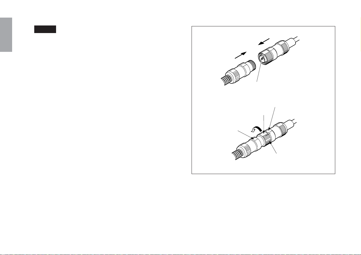
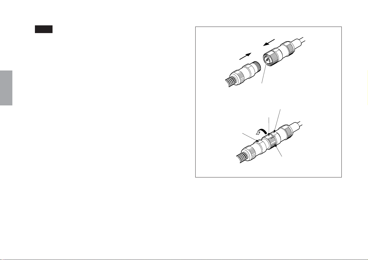
1
2
Female side
Rotate by hand
Part B
Male side
Notch matches
Part C
Part A
Male side
20
Female side
Coupling nut
Fig. 3-16
(E)
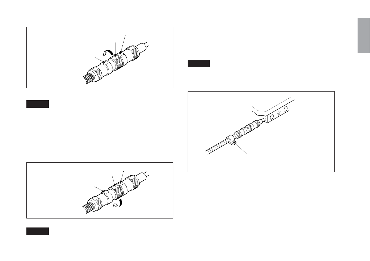
3 Use a spanner on
parts A and B to
turn in the direction
of the arrow.
Female side
3/4 of a
revolution
Part B
Fig. 3-17
Part A
Part C
Male side
Note
• Use a wrench or other tool to tighten the connectors to a torque
of 150 to 250 N·cm. Waterproof performance cannot be
guaranteed unless the connectors are tightened to the specified
torque.
• Do not tighten the connectors by attaching wrenches to parts A
and C.
<8> Mounting the conduit cable
Fix the conduit cable with cable clamps so that they will not
interfere with moving parts of the machine.
Note
Care should be taken at this time as it may be necessary to
provide the cable with some leeway with respect to the machine
operation.
English
To remove
Use a spanner on parts
A and C to turn in the
direction of the arrow.
Female side
Part C
Part A
Part B
Fig. 3-18
Male side
Note
Do not loosen the connectors by attaching wrenches to parts A
and B.
Secure the cable clamp using a M4×10 cable
clamp screw (accessory).
Fig. 3-19
(E
) 21

English
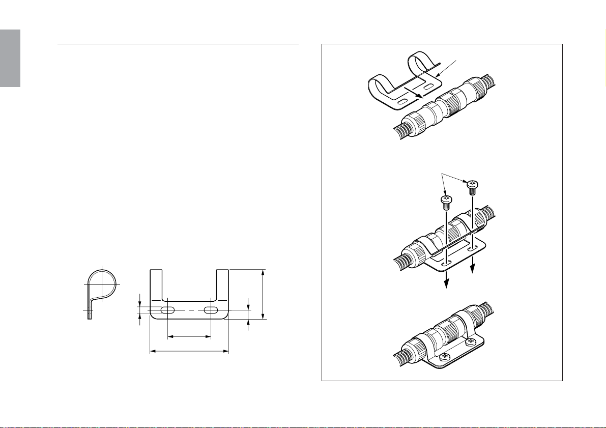
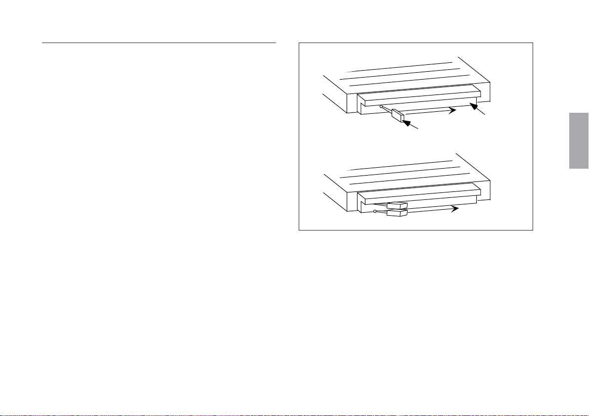
<9> Mounting the round connectors
Secure the connected male and female round connectors with the
accessory clamp.
Be sure to secure the connectors, as they are dangerous if loose.
1 Fit the connectors into the open side of the clamp.
2 Tighten the top and bottom edges of the clamp together
using the two accessory screws (+B M4×10).
3 Tighten the screws firmly until the top and bottom edges of
the clamp touch.
Then check that the connectors are secured firmly.
Clamp mounting dimensions and outer dimensions
6/0.23"
34/0.33"
4.4/0.17"
30/1.17"
54/2.11"
Clamp
Tighten with binding pan
head screws (+B M4×10).
22
The height dimension after mounting should be the same as the
outer diameter of the connectors.
(E)
Tighten until the
edges touch.
Fig. 3-20

<10> Connecting the interface unit to a counter
unit
When the connection cable must be electrically adjusted for the
SR138R series, see “4. Electrical Adjustment of the Connection
Cable Circuit”.
1 Check that the counter unit power is off. Then, connect the
interface unit of the connection cable with the connector 1-3
on the rear panel of counter unit.
Note
Check the scale unit mounting axis and counter unit insertion.
2 Secure the interface unit using the screws. (Tightening
torque: 60 N·cm)
Rear panel of counter unit
Fig. 3-21
Interface unit
English
(E
) 23

English
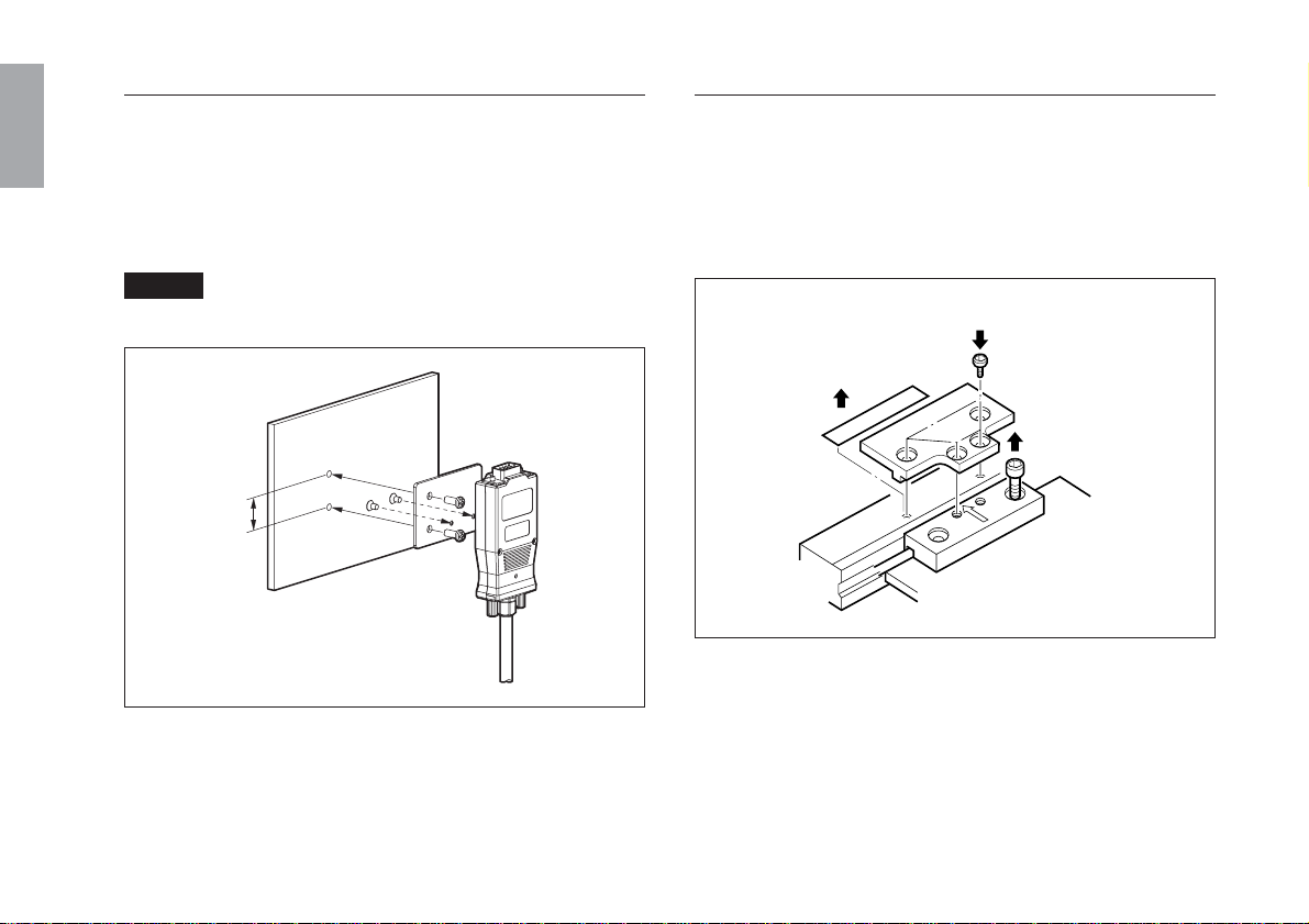
<11> Connecting the interface unit to a
controller
1 Use the screw (M3×5) to mount the supplied fixing plate to
the interface unit.
2 Use the supplied screw (M4×5) to secure 1 to the mounting
surface.
Note
Prepare two M4 tap holes on the mounting surface.
20/0.79"
Fig. 3-22
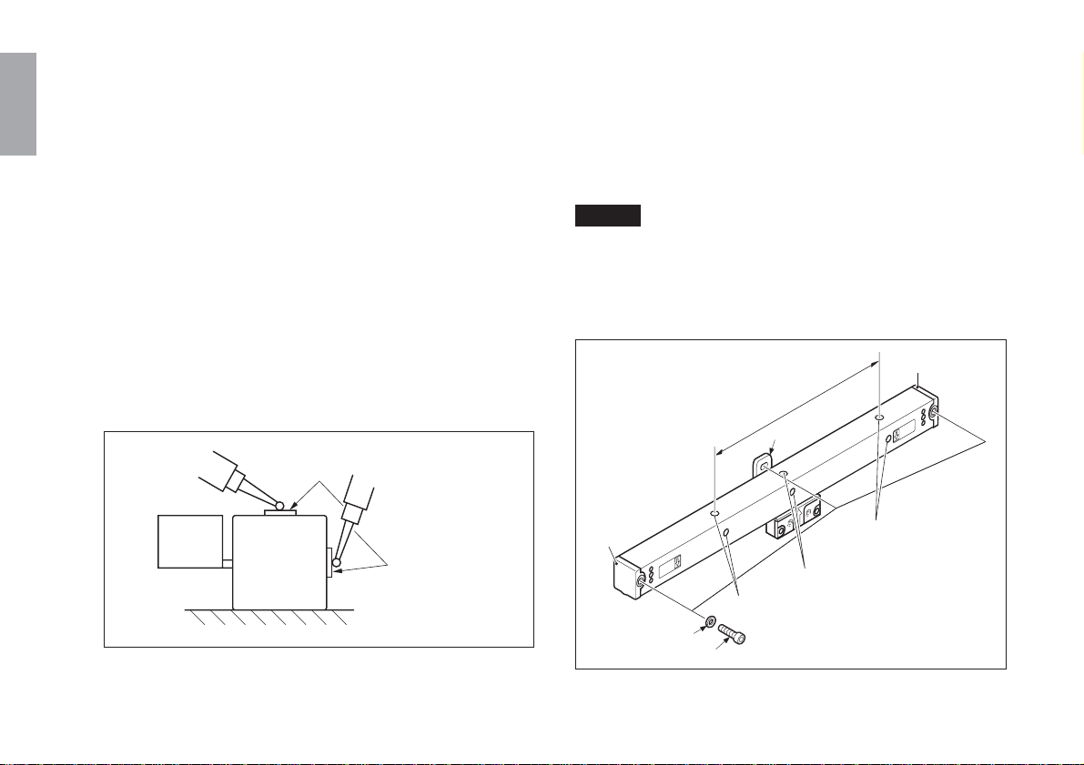
<12> Removal of the scale unit
When removing a mounted scale unit from the machine, be sure
to secure the slider part to the scale part with the slider holder.
Follow the numerical sequence.
2 Secure the slider part using four M2.6 cap screws.
1 Peel off the
screening plate.
3 Loosen screws and
remove them from
machine.
Fig. 3-23 Removing a scale unit
Securing the slider part to the scale part keeps the alignment of
the scale part and slider part after removal from the machine and
makes reinstallation easy.
24
(E)

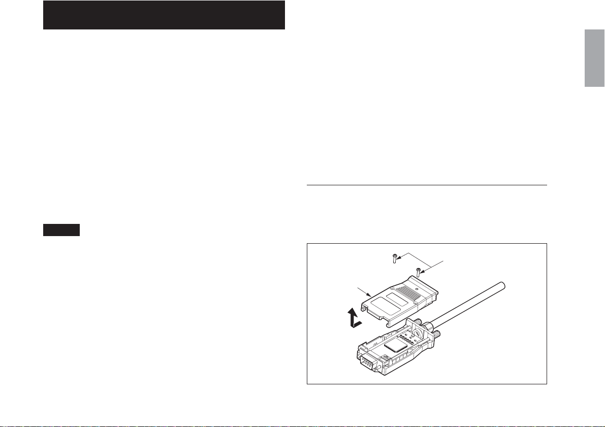
4.
Electrical Adjustment of the Connection Cable Circuit
(SR138R series only)
* The operations described in this section are not required for the
GB-ER series which are shipped together with the connection
cable in the electrically adjusted condition.
When connecting the SR138R series with a counter unit, use a
CH04 series (optional) connection cable.
The connection cable must be electrically adjusted together with
the used scale unit. Perform this adjustment according to the
procedures outlined below.
Electrical adjustment is performed in order to optimize the A/B
quadrature signal from the scale unit. Therefore, if the adjustment
is not performed as specified, the scale accuracy specifications
will not be satisfied.
Note
When the scale unit and counter unit connection cable (CH04
series) are ordered together, they are shipped in the adjusted
condition so no adjustment is necessary. Connect the scale unit
and cable so that the serial No. on the scale unit matches the
combination No. on the connection cable.
Required items
• Oscilloscope
(Sensitivity: 0.01 V or more,
frequency bandwidth: 1 MHz or more)
Input sensitivity : DC0.1 V/div (1 using a 10 : 1 probe)
Horizontal axis sweep : 50 ms/div to 0.5 ms/div
Trigger source : INT
Trigger mode : AUTO
• Standard screwdriver (for rotating the trimmer)
• Phillips screwdriver
(for removing and mounting the upper case)
<1> Removing the upper case
Remove the two screws M2×8 mounting the upper case of the
interface unit and remove the upper case.
M2×8
Upper case
English
Fig. 4-1
(E
) 25

English
RV1 (SIN DC)
RV3 (COS DC)
RV5 (REF DC)
TP1 (SIN)
TP2 (COS)
TP3 (REF)
TP4 (GND)
CL1 (ZG)
CN2-5pin (Z)
RV6 (REF amplitude)
Switch 1
(Reference point
POS1sw)
Switch 2
(Reference point
POS2sw)
RV4 (COS amplitude)
RV2 (SIN amplitude)
CH1CH2
Oscilloscope
Probe
Signal adjustment
section-datailed view
Interface unit
26
(E)
<2> SIN/COS signal check
Note
• Be sure that the interface unit is turned off before attaching or
removing the probe of the oscilloscope.
• The check pin of the interface unit has little physical strength,
and so use an IC clip or other implement to connect.
(Recommended IC clip: SMG50 grabber clip by Tektronix,
etc.)
• Check that the interface unit is turned off.
• Refer to section for removing and attaching the cover of the
interface unit.
1 Connect the CH1 probe of the oscilloscope to the TP1 (SIN)
and TP4 (GND) check pins of the interface unit.
2 Connect the CH2 probe of the oscilloscope to the TP2 (COS)
and TP4 (GND) check pins of the interface unit.
Fig. 4-2

3 Set the TIME/DIV switch of the oscilloscope to the X-Y
mode.
4 Set the deviation sensitivity (VOLTS/DIV) of CH1 and CH2
of the oscilloscope to 0.2 V/DIV.
5 Set the input coupling switches of CH1 and CH2 of the
oscilloscope to GND and adjust the oscilloscope to locate
the signal at the bottom left of the screen. (Fig. 4-3)
Fig. 4-3
6 Set the input coupling switches of CH1 and CH2 of the
oscilloscope to DC.
7 Turn on the interface unit.
8 SIN/COS signal DC level check and adjustment
Move the scale part or slider part, and check that the
Lissajous' curve center (Fig. 4-4) is within the specified
value over the entire length.
If the center is not within the specified value, adjust the DC
level so that the Lissajous' curve center is set at the specified
value.
Specified value of Lissajous' curve center = 0.9 V ±0.02 V
DC level adjustment trimmer RV1 (SIN) : a direction
RV3 (COS) : b direction
English
a
b
Fig. 4-4
(E
) 27
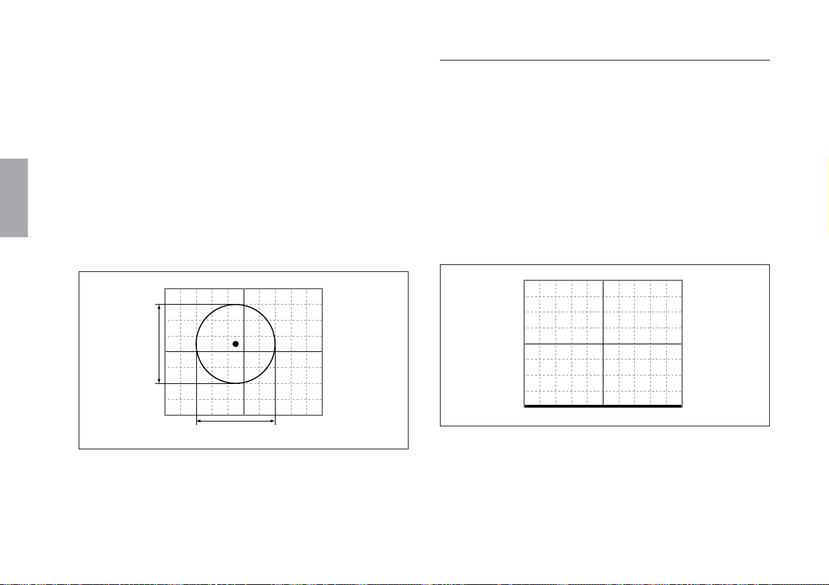
English
9 SIN/COS signal amplitude check and adjustment
Move the scale part or slider part, and check that the
Lissajous' curve amplitudes A and B (Fig. 4-5) are within the
specified value over the entire length.
If an amplitude is not within the specified value, adjust the
amplitude so that the Lissajous' curve amplitude A or B is set
at the specified value.
Specified value of Lissajous' curve amplitude =
1.0 Vp-p ±0.06 V
Amplitude adjustment trimmer RV2 (SIN) : A direction
RV4 (COS) : B direction
A
<3> Reference point signal check
Connect the oscilloscope CH1 probe to the TP3 and TP4 check
pins of the interface unit.
1 Set the TIME/DIV switch of the oscilloscope to 200 ms.
2 Set the CH1 deflection sensitivity (VOLTS/DIV) of the
oscilloscope to 0.2 V/DIV.
3 Set the input coupling switch of CH1 of the oscilloscope to
GND, and adjust the oscilloscope to locate the signal at the
bottom edge of the screen. (Fig. 4-6)
28
! Turn off the interface unit.
(E)
B
Fig. 4-5
Fig. 4-6
4 Set the input coupling switch of CH1 of the oscilloscope to
DC.
5 Turn on the interface unit.
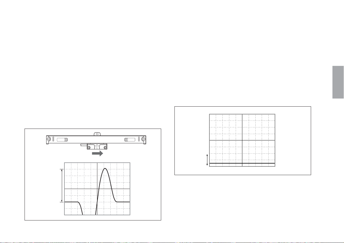
6 Reference point signal single-amplitude check and
adjustment
Move the slider part in the right direction with respect to the
scale part, and pass through the reference point.
When moving the slider head, check that the reference point
top-side single amplitude C (Fig. 4-7) is within the specified
value.
If it is not within the specified value, adjust the amplitude so
that the reference point top-side single amplitude C is set at
the specified value.
Specified reference point value of single amplitude =
1.0 V ±0.04 V
Reference point amplitude adjustment trimmer RV6
Reference point detection
check direction
7 Reference point signal DC level check and adjustment
Move the scale part or slider part to a position having no
reference point.
When moving the slider head, check that the reference point
signal DC level c (Fig. 4-8) is within the specified value.
If it is not within the specified value, adjust the DC level so
that the reference point signal DC level c is set at the
specified value.
Specified reference point value of DC level =
0.2 V ±0.02 V
Reference point amplitude adjustment trimmer RV5
c
English
C
Fig. 4-7
Fig. 4-8
(E
) 29
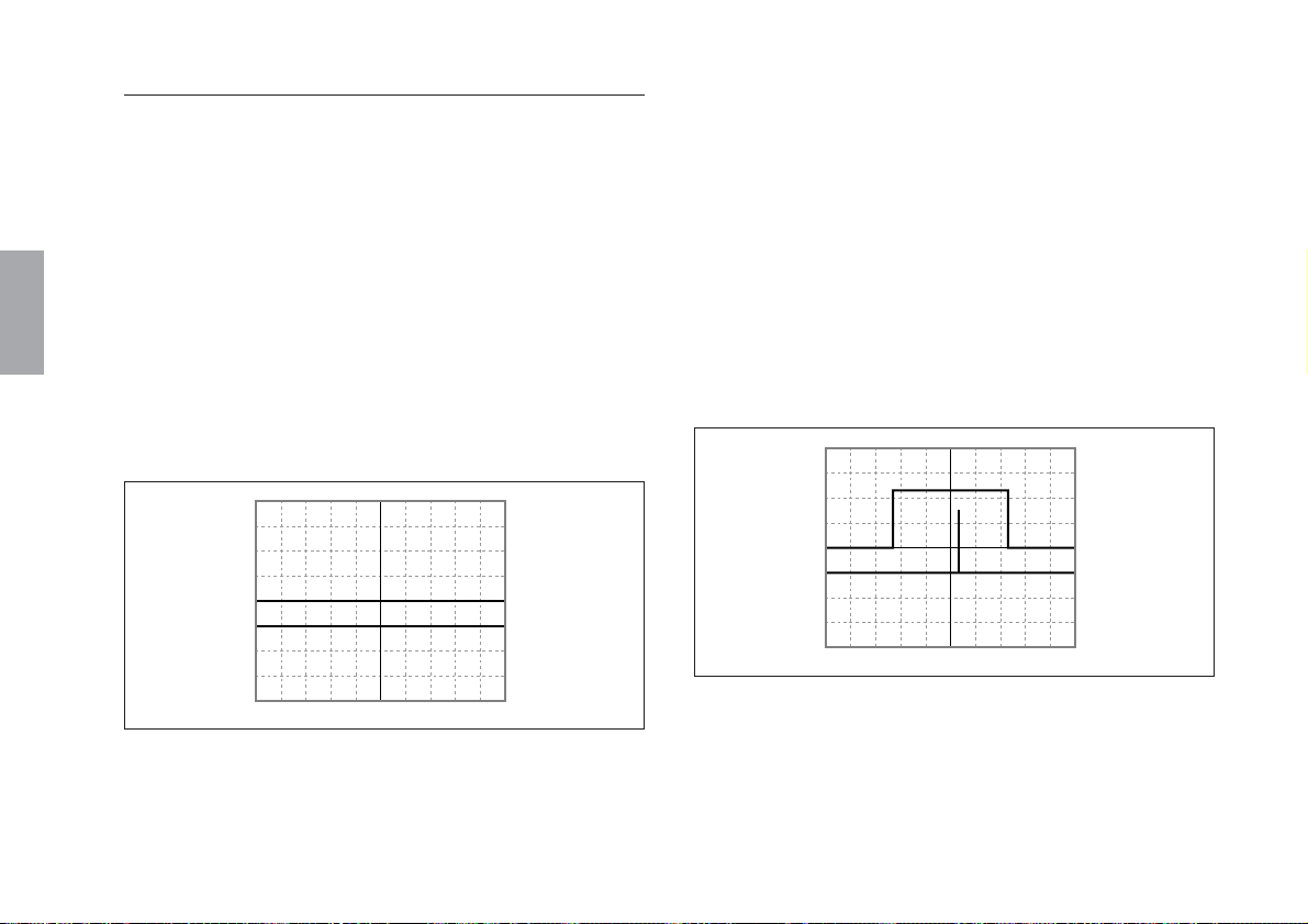
English
<4> Reference point position check
1 Connect the CH1 probe of the oscilloscope to the CL1 (ZG)
check land and TP4 (GND) check pin of the interface unit.
2 Connect the CH2 probe of the oscilloscope to the CN2-5 pin
(Z) and TP4 (GND) check pin of the interface unit.
3 Set the TIME/DIV switch of the oscilloscope to 200 ms.
4 Set the deflection sensitivity (VOLTS/DIV) of CH1 and
CH2 of the oscilloscope to 2V/DIV.
5 Set the input coupling switch CH2 of the oscilloscope to
GND, and adjust the oscilloscope to locate CH1 in the screen
center.
Adjust the oscilloscope to locate CH2 in one grid line below.
(Fig. 4-9)
CH1 (ZG)
CH2 (Z)
6 Set the input coupling switches CH1 and CH2 of the
oscilloscope to DC.
7 Turn on the interface unit.
8 Position setting of reference point gate signal (CL1)
and reference point output signal (CN2-5pin)
Move the scale part or slider part and pass through the
reference point.
When passing through the reference point, set the switch 1/2
(reference point POS1/2SW) so that the reference point
output signal is output at the position nearest to the center of
the reference point gate signal. (Fig. 4-10)
CH1 (ZG)
CH2 (Z)
Fig. 4-10
30
Fig. 4-9
(E)
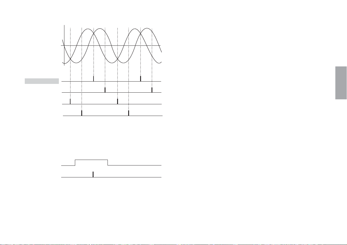
SIN signal
COS signal
MODE1 MODE2
ON ON
Approx. 45°
OFF ON
Approx. 135°
ON OFF
Approx. 225°
OFF OFF
Approx. 315°
The reference point output signal is the
logical product of one of the four one-cycle
reference points that was selected by the
switch setting and the reference point gate.
Reference point gate
signal
Reference point
output
When both mode switches 1 and 2 are on
English
(E
) 31
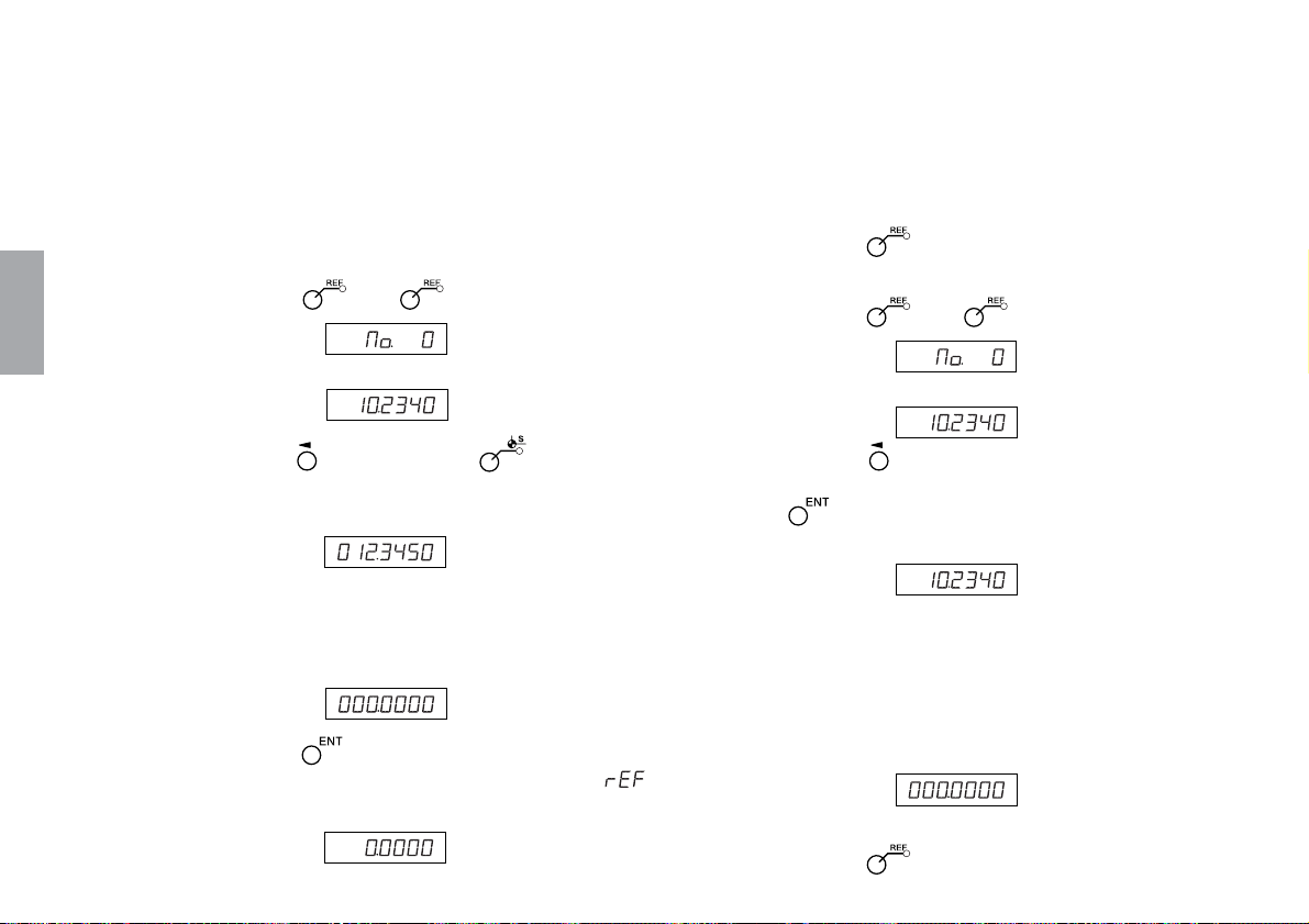
9 Reference point operation check (When checking the
reference point using LH70/LH71)
Use the reference point load and the reference point hold to
check the reference point in both directions.
1. Connect the interface unit to the LH70/LH71 counter
unit, and then turn it on.
2. Enter “000.0000” for the reference point offset amount.
1) Press the
key. ( lamp lights up)
5) Move the scale part or slider part until it goes past the
reference point.
A beeping sound is made when the reference point is
detected.
*
When the reference point is detected, counting starts.
6) Press the key to exit the mode.
3. Checking the reference point in both directions
1) Press the key. ( lamp lights up)
English
32
(E)
Display ↓
(Current value (ABS))
2) Press the , and then press the key.
The stored offset value (value displayed when the
reference point is loaded) is displayed.
Display (Example: Distance
from the reference
point to the datum
point)
3) Enter the offset (000.0000) using the numeric key.
Display (000.0000)
4) Press the key.
A reference point wait status is activated. (
value flashes)
Display (Flashes)
Display ↓
(Current value (ABS))
2) Press the key corresponding to the axis to be put
into a reference point hold status, and then press the
key.
A reference point wait status is activated. (Current value)
Display (Lights up)
3) When the reference point is passed through from
the opposite direction that it was passed through in
step 2), the count at the reference point position is
held. (Axis label flashes)
*A beeping sound is made when the reference point
is detected.
Display
4) Check that the value that is held is “0”.
5) Press the
key to exit the mode.

5. Specifications
5-1. General Specifications
Scale unit
Measuring length:
50/1.9, 100/3.9, 150/5.9, 200/7.8, 250/9.8, 300/11.8,
350/13.7, 400/15.7, 450/17.7, 500/19.6, 550/21.6, 600/23.6,
650/25.5, 750/29.5, 850/33.4, 950/37.4, 1050/41.3,
1250/49.2, 1400/55.1, 1600/62.9, 1850/72.8, 2050/80.7,
2200/86.6 mm/inch
Overall length:
Measuring length+104 mm/4.1"
(Measuring length 200 mm/7.8" or less)
Measuring length+120 mm/4.72"
(Measuring length 250 mm/9.8" or more)
Maximum travel:
Measuring length+14 mm/0.55" (Measuring length 200 mm/7.8"
or less, 7 mm/0.275" each at right and left)
Measuring length+30 mm/1.2" (Measuring length 250 mm/9.8"
or more, 15 mm/0.6" each at right and left)
Scale accuracy (at 20°C/68°F):
(SR138R series)
Metric: ±(0.0025+0.0025×measuring length in meters) mm
+
Inch : ±(0.0001
0.0000025×measuring length in inches) inch
Input/output signals:
Output signal :A/B/Z signal
Power supply : DC 5 V ±5 %
Connector : D-sub 9-pin
Connector pin layout : see “Dimensions”
Resolution : 0.5 µm
Response speed:
Scale signals : 60 m/min
Reference point signal : 60 m/min
Reference point position : One center location in
measuring length
Cable length : Max. 30 m/98.4 ft
Parallelism : 0.1 mm/0.004"
Current consumption : Max. 200 mA
–6
Thermal expansion coefficient: (11±1)×10
Operating temperature :0 to 40°C/32 to 104°F
Storage temperature : –10 to +50°C/14 to 122°F
/°C
Connection cable
(CH04: included only with the GB-ER series)
Cable length : 3 m/9.8 ft
Design and specifications are subject to change without notice.
(E
English
) 33
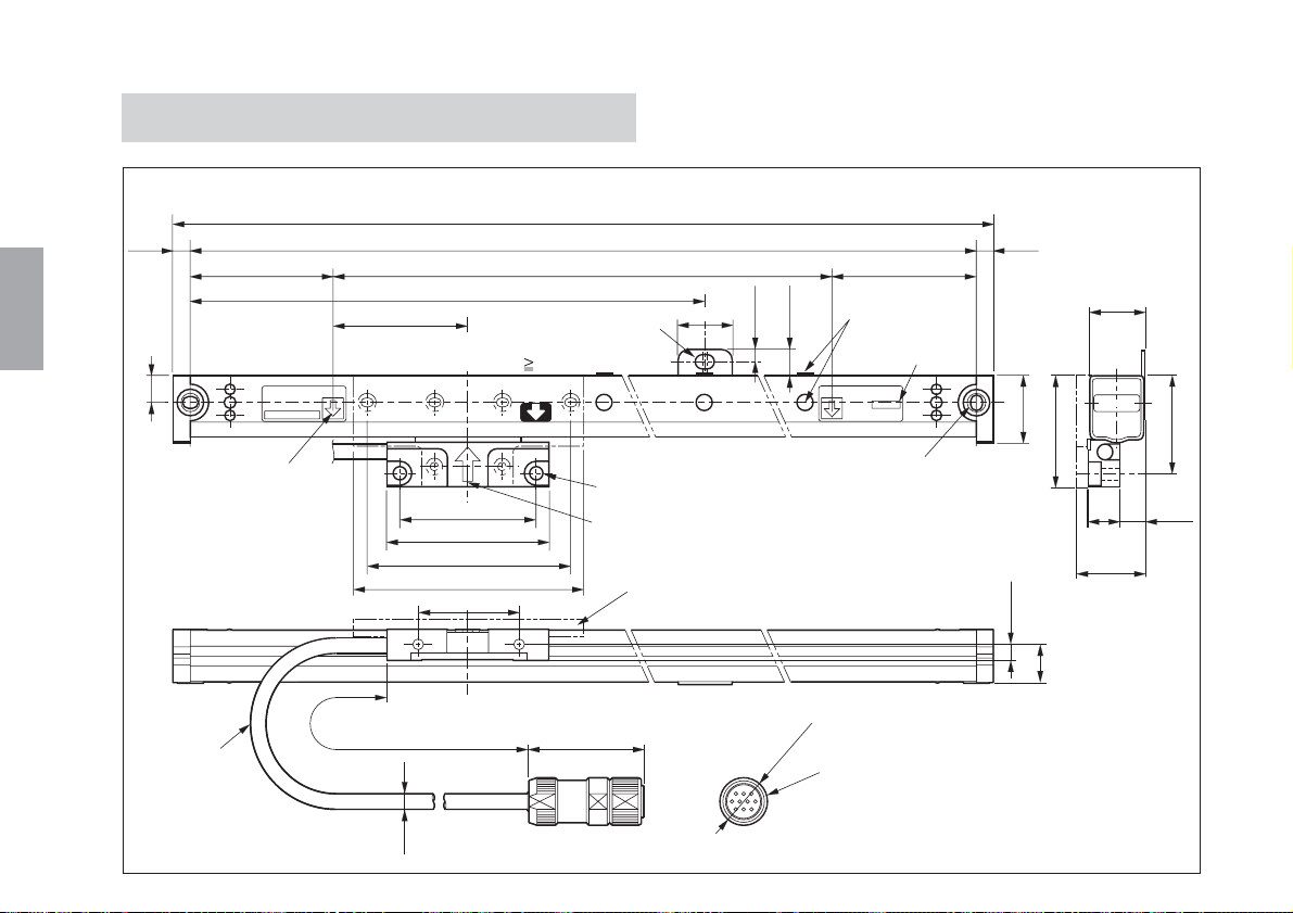
5-2. Dimensions
English
34
(E)
Scale unit
6.5
0.26"
9.5/0.37"
Head cable
(C)
SR138–
R
* * *
Measuring
length mark
Overall length=A
Mounting hole pitch=B
Measuring length=L
Mounting hole pitch×1/2
D
Center foot plate
5×7/0.2"×0.28" long hole (Mounting hole)
(Measureing length L
1050 mm/41.34")
50/1.97"
60/2.36"
75/2.95"
85/3.35"
36/1.42"
Cable length=300/11.81"
ø5.5
0.22"
44/1.73"
20/0.79"
5/0.2"
2-ø5/0.2" hole, ø9/0.35" hole
Slider center
Slider holder
ø18/0.
Alignment mark
10.5/0.41"
Serial No.
******
2–4.5×5.5/0.18"×0.22"
long hole (Mounting hole)
1"
7
Round connector (male)
(C)
Serial No.
6.5
0.26"
25/0.98"
6/0.24"
15
21/0.83"
42/1.65"
12
0.47"
25/0.98"
0.59"
Unit : mm/inch
36.5/1.44"
9
0.35"
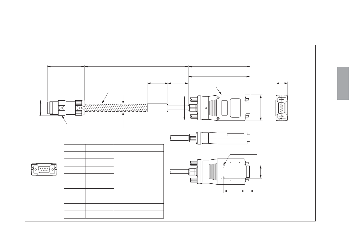
Connection cable (CH04 : included only with the GB-ER series)
Cable length
ø9/0.35"
30/1.18"
30/1.18"
36/1.41"
ø18/0.71"
44/1.72" (91/3.58")
Conduit cable
Round connector
(female)
Interface connector (D-sub 9-pin male) pin layout
Pinno. Signal Remarks
15
69
1A
2 *A
3B
4 *B
5Z
6 *Z
70V
8 +5Vinput DC+5V±5%
90V
Differentialoutput
(Conformsto
EIA-422)
Minimumphase
difference:200ns
(86.5/3.40")
Interface unit
**
2-M3 depth 3
(31/1.22")
38/1.50"
20
(7/0.28")
(17.7/0.70")
English
0.79"
Unit : mm/inch
(E
) 35
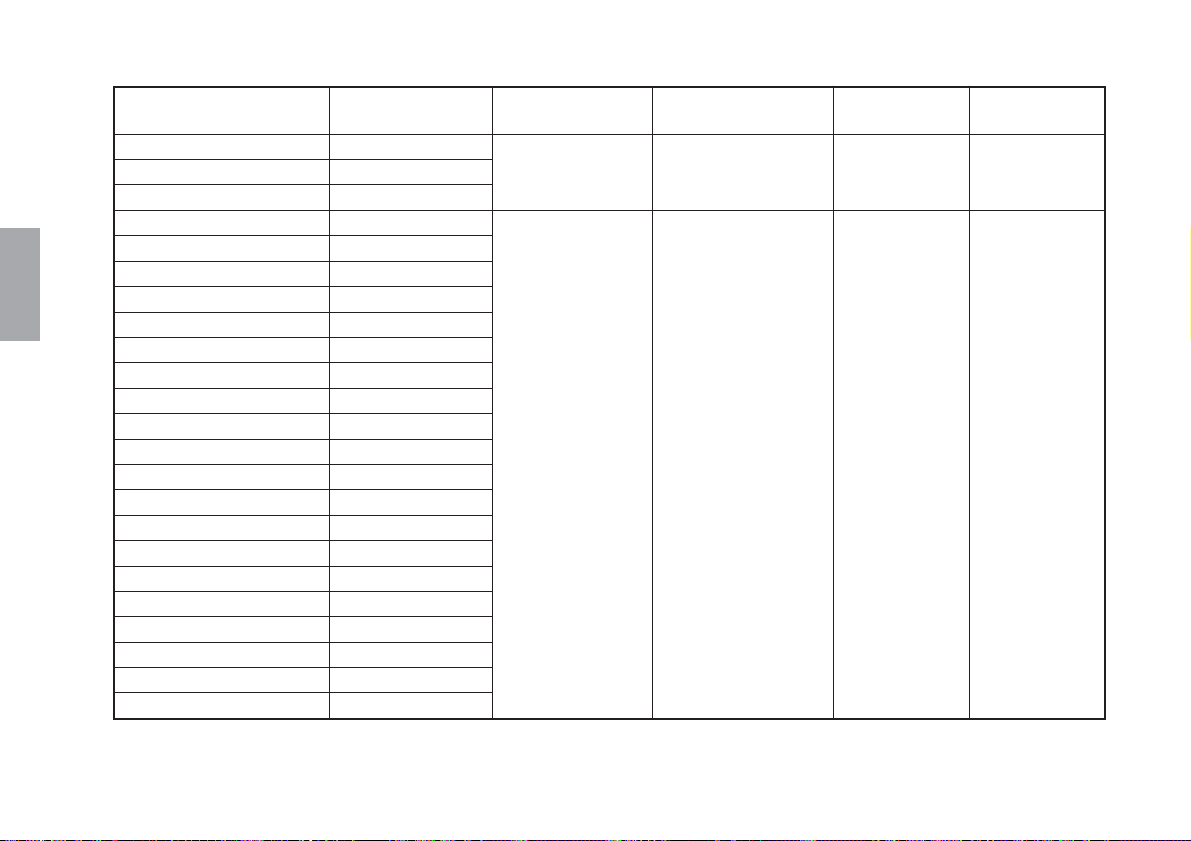
English
Model name
GB-005ER / SR138-005R
GB-010ER / SR138-010R
GB-015ER / SR138-015R
GB-020ER / SR138-020R
GB-025ER / SR138-025R
GB-030ER / SR138-030R
GB-035ER / SR138-035R
GB-040ER / SR138-040R
GB-045ER / SR138-045R
GB-050ER / SR138-050R
GB-055ER / SR138-055R
GB-060ER / SR138-060R
GB-065ER / SR138-065R
GB-075ER / SR138-075R
GB-085ER / SR138-085R
GB-095ER / SR138-095R
GB-105ER / SR138-105R
GB-125ER / SR138-125R
GB-140ER / SR138-140R
GB-160ER / SR138-160R
GB-185ER / SR138-185R
GB-205ER / SR138-205R
GB-220ER / SR138-220R
Measuring length
(L)
50 mm/1.9"
100 mm/3.9"
150 mm/5.9"
200 mm/7.8"
250 mm/9.8"
300 mm/11.8"
350 mm/13.7"
400 mm/15.7"
450 mm/17.7"
500 mm/19.6"
550 mm/21.6"
600 mm/23.6"
650 mm/25.5"
750 mm/29.5"
850 mm/33.4"
950 mm/37.4"
1050 mm/41.3"
1250 mm/49.2"
1400 mm/55.1"
1600 mm/62.9"
1850 mm/72.8"
2050 mm/80.7"
2200 mm/88.6"
Overall length
(A)
Measuring length
+104 mm/4.1
Measuring length
+120 mm/4.7"
"
Mounting hole pitch
(B)
Measuring length
+91 mm/3.6"
Measuring length
+107 mm/4.2"
C
45.5 mm/1.8"
53.5 mm/2.1"
D
Measuring
length×1/2
50 mm/2"
36
(E)

6. Trouble Information
■ When the machine overruns, cables become damaged, the
scale unit becomes deformed or other situations arise which
may affect scale performance, the unit must be repaired.
• In these case, stop the machine immediately and consult
your Magnescale Co., Ltd. distributor.
■ The scale unit may not be repairable, depending on the extent
of the damage.
Regular cleaning is recommended in order to prevent these types
of trouble beforehand.
• Clean away any cutting scraps at the start and finish of work
each day to prevent cutting scraps from accumulating
around the scale unit.
• Accumulated cutting scraps may impede the sliding motion
of the scale unit and result in malfunction.
• Avoid using an air gun or similar device to clean away the
cutting scraps. Although the running portions of the scale
unit are sealed, the scale unit does not have a completely
sealed structure. If an air gun or similar device is used,
cutting scraps and other objects may enter the sealed
portions of the scale unit and result in malfunction.
English
(E
) 37

38
(E)

■ Allgemeine Vorsichtsmaßnahmen
Beim Einsatz von Geräten von Magnescale Co., Ltd. sind die
folgenden allgemeinen Vorsichtsmaßnahmen zusätzlich zu den in
der vorliegenden Anleitung jeweils speziell angegebenen
Warnhinweisen zu beachten, um einen korrekten Einsatz des
Gerätes zu gewährleisten.
• Vor und während des Betriebs sicherstellen, dass das Gerät
korrekt funktioniert.
• Geeignete Sicherheitsvorkehrungen zur Vermeidung von
Schäden für den Fall ergreifen, dass am Gerät eine Störung
auftritt.
• Wird das Gerät außerhalb der angegebenen Spezifikationen
und Einsatzzwecke verwendet oder werden am Gerät
Änderungen vorgenommen, kann keine Garantie für Funktion
und Leistung übernommen werden.
• Beim Einsatz des Gerätes mit einem anderen nicht empfohlenen
Gerät werden u.U. je nach Betriebsbedingungen die in der
vorliegenden Anleitung aufgeführten optimalen Funktionen und
Leistungen nicht erreicht. Daher die Kompatibilität im Voraus
gründlich prüfen.
■ Vorsichtsmaßnahmen zum Einsatz unter den
folgenden Umweltbedingungen
1 Bei Verwendung von wassermischbarer Schneidflüssigkeit,
oder beim Schneiden metallischer oder nichtmetallischer
(Keramik, Glasfaser usw.) Objekte:
• Die Maßstabseinheit so montieren, dass sie nicht direkt
wassermischbarer Schneidflüssigkeit oder Spänen
ausgesetzt ist.
• Eine Schutzhaube anbringen, um das Eindringen von
wassermischbarem Schneidflüssigkeitsnebel oder Staub in
das Innere der Maßstabseinheit zu verhüten.
2 Bei Montage an einer Massivumformmaschine oder einer
anderen Maschine, die sich mit hoher Geschwindigkeit über
lange Zeitspannen innerhalb eines bestimmten Bereiches hin
und her bewegt:
• Regelmäßig Öl oder Sprühschmiermittel (CRC, WD40 usw.)
auftragen.
Bei Verwendung unter den in 1 oder 2 genannten Bedingungen
sind die obigen Maßnahmen unbedingt zu treffen. Wird dies
versäumt, ist keine ausreichende Qualität gewährleistet.
(G
) i

Sicherheitsmaßnahmen
Bei dem Entwurf von Magnescale Co., Ltd. Produkten wird größter Wert auf die Sicherheit gelegt. Unsachgemäße
Handhabung während des Betriebs oder der Installation ist jedoch gefährlich und kann zu Feuer, elektrischen
Schlägen oder anderen Unfällen führen, die schwere Verletzungen oder Tod zur Folge haben können. Darüber
hinaus kann falsche Behandlung die Leistung der Maschine verschlechtern.
Beachten Sie daher unbedingt die besonders hervorgehobenen Vorsichtshinweise in dieser Bedienungsanleitung,
um derartige Unfälle zu verhüten, und lesen Sie die folgenden Sicherheitsmaßnahmen vor der Inbetriebnahme,
Installation, Wartung, Inspektion oder Reparatur dieses Gerätes oder der Durchführung anderer Arbeiten durch.
Bedeutung der Warnhinweise
Bei der Durchsicht dieses Handbuchs werden Sie auf die folgenden
Hinweise und Symbole stoßen. Machen Sie sich mit ihrer
Bedeutung vertraut, bevor Sie den Text lesen.
Warnung
Eine Missachtung dieser Hinweise kann zu Feuer, elektrischen
Schlägen oder anderen Unfällen führen, die schwere Verletzungen
oder Tod zur Folge haben können.
Vorsicht
Eine Missachtung dieser Hinweise kann zu elektrischen Schlägen
oder anderen Unfällen führen, die Verletzungen oder
Sachbeschädigung der umliegenden Objekte zur Folge haben
können.
Zu beachtende Symbole
VORSICHT ELEKTRISCHER
SCHLAG
Symbole, die Handlungen verbieten
NICHT
ZERLEGEN
Symbole, die Handlungen vorschreiben
Hinweis
Diese Hinweise sollten beachtet werden, um eine korrekte
ii
(G)
Handhabung des Gerätes zu gewährleisten.
STECKER ABZIEHEN

Warnung
• Betreiben Sie dieses Gerät nur mit der vorgeschriebenen Versorgungsspannung, da
• Führen Sie Installationsarbeiten nicht mit nassen Händen aus, da hierbei die Gefahr
• Unterlassen Sie jeden Versuch, das Gerät zu zerlegen oder umzubauen, da dies zu
Vorsicht
• Überprüfen Sie vor Arbeitsbeginn unbedingt den Zustand von Maschine und
• Schalten Sie unbedingt die Strom- und Luftversorgung sowie andere
anderenfalls die Gefahr von Feuer oder elektrischen Schlägen besteht.
elektrischer Schläge besonders groß ist.
Verletzungen oder Beschädigung der internen Schaltungen führen kann.
Vorrichtungen, um die Arbeitssicherheit zu gewährleisten.
Antriebskraftquellen aus, bevor Sie Arbeiten an der Maschine ausführen.
Anderenfalls kann es zu Feuer oder Unfällen kommen.
• Achten Sie beim Einschalten der Stromversorgung usw. zum Betrieb der Maschine
darauf, dass Sie sich nicht die Finger in peripheren Maschinen und Vorrichtungen
klemmen.
(G
) iii

Hinweise zur Handhabung
Installationshinweise
Beachten Sie bei der Installation dieses Gerätes die folgenden Punkte, um die
Einstreuung von Rauschen und elektromagnetischen Wellen von anderen Geräten zu
verhüten.
1. Verlegen Sie Zuleitungskabel und Verbindungskabel nicht zusammen mit
Starkstromkabeln.
2. Halten Sie bei der Installation des Gerätes einen Mindestabstand von 0,5 m zu
Hochspannungs-, Starkstromquellen oder Hochleistungsrelais ein.
3. Bringen Sie das Gerät auf keinen Fall in die Nähe von Magneten oder Quellen
elektromagnetischer Wellen.
Hinweis
• Magnetische Futter oder andere Magnetkraftquellen von ungefähr 6 × 10⁻² [T]
sollten mindestens 50 mm von den Seitenflächen und mindestens 10 mm von den
Öffnungen des Stahlgehäuses der Maßstabseinheit entfernt gehalten werden.
• Falls das Gerät in der Nähe von Magnetkraftquellen installiert werden muss,
treffen Sie unbedingt angemessene Maßnahmen zum Schutz vor
elektromagnetischer Beeinflussung.
iv
4. Um durch Rauschen verursachte Störungen zu vermeiden, sollten Maßstab und
Schieber unbedingt geerdet werden.
(G)

Hinweise zum Installationsort
1. Um eine möglichst präzise Positionierung zu erzielen, empfiehlt es sich, die
Maßstabseinheit möglichst nahe am Werkstück oder zum messenden Objekt
einzubauen.
(Je weiter die Maßstabseinheit vom Werkstück entfernt eingebaut wird, desto
größer werden mechanische Fehler.)
2. Verwenden Sie die Maßstabseinheit innerhalb eines Umgebungstemperaturbereichs
von 0 °C bis 40 °C. Einbauorte vermeiden, wo die Maßstabseinheit direkter
Sonneneinstrahlung und Wärmequellen, wie z.B. Motoren, ausgesetzt ist.
3. Keine Gegenstände auf die angebaute Maßstabseinheit legen und nicht darauf
treten: übermäßig starke Einwirkung von Kräften auf die Maßstabseinheit erzeugt
Störungen.
(G
) v

vi
(G)

Inhaltsverzeichins
1. Übersicht..................................................................... 2
1-1. Einleitung ..................................................................... 2
1-1-1. Serie SR138R ....................................................... 2
1-1-2. Serie CH04 ........................................................... 2
1-1-3. Serie GB-ER ......................................................... 2
1-1-4. Serie CE10............................................................ 2
1-2. Hauptmerkmale ............................................................ 2
1-3. Anordnung der Teile .................................................... 3
1-4. Systemaufbau ............................................................... 3
2. Bezeichnung und Funktion der Teile....................... 5
2-1. Maßstabseinheit ........................................................... 5
2-2. Anschlusskabel ............................................................ 7
3. Montagemethode ....................................................... 8
3-1. Vor der Montage zu beachtende Vorsichtshinweise ... 8
3-2. Vorsichtsmaßnahmen bei der Montage ....................... 9
3-2-1. Überprüfen der Montagemethode ........................ 9
3-2-2. Einstellen des Bewegungsbereichs .................... 10
3-2-3. Schutz des Kopfanschlusskabels ....................... 10
3-2-4. Anbringen einer Schutzhaube ............................ 10
3-3. Zur Montage benötigte Teile ..................................... 11
3-4. Einbaumaße ................................................................ 12
<1> Wenn die Parallelität und Ebenheit der
Maßstab-Einbaufläche bereits
zufriedenstellend genau sind ................... 12
<2> Wenn es sich bei der Einbaufläche um eine
Gussfläche handelt ..................................13
<3> Montage des Schiebers ..............................15
<4> Entfernen des Schieberhalters ................... 18
<5> Kontrolle des Bewegungsbereichs ............. 18
<6> Einbau des Kopfkabels ...............................18
<7> Anschließen der Kabel ................................19
<8> Einbau des Zuleitungskabels ...................... 21
<9> Anschließen der Rundsteckverbinder .........22
<10> Anschließen der Schnittstelleneinheit an
eine Zählereinheit .................................... 23
<11> Anschließen der Schnittstelleneinheit an
ein Steuergerät ........................................ 24
<12> Ausbau der Maßstabseinheit ......................24
4. Elektrische Einstellung des
Anschlusskabel-Schaltkreises ............................... 25
<1> Ausbau des oberen Gehäuses ................... 25
<2> SIN/COS-Signalüberprüfung ....................... 26
<3> Prüfung des Bezugspunktsignals ............... 28
<4> Prüfung der Bezugspunktposition ...............30
5. Technische Daten .................................................... 33
5-1. Allgemeine Daten ...................................................... 33
5-2. Abmessungen ............................................................. 34
6. Informationen für den Störungsfall ....................... 37
(G
Deutsch
) 1

1. Übersicht
Deutsch
1-1. Einleitung
1-1-1. Serie SR138R
Bei den Modellen der Serie SR138R handelt es sich jeweils um
einen linearen Maßstab mit eingebautem Bezugspunkt.
Die relativen Positionen von Maßstab und Schieber werden mit
Hilfe eines Schieberhalters eingestellt und gesichert.
Unbedingt darauf achten, diesen Maßstab ausschließlich mit dem
Anschlusskabel CH04 (Sonderzubehör) zu verwenden.
Hinweis
Falls der Maßstab der Serie SR138R und das Anschlusskabel
CH04 separat bestellt wurden, muss vor der Inbetriebnahme eine
elektrische Einstellung für das CH04 vorgenommen werden.
Dies ist nicht erforderlich, wenn die elektrische Einstellung zum
Zeitpunkt der Bestellung in Auftrag gegeben wurde.
1-1-2. Serie CH04
Dies ist ein Spezialkabel mit einer integrierten Schaltung zur
Umwandlung von Signalen der Serie SR138R in ein Allzweck-A/
B-Quadratur-Ausgangssignal. Der Einsatz dieses Kabels mit den
Modellen der Serie SR138R gestattet den Anschluss von
Magnescale Co., Ltd.-Anzeigeeinheiten (z.B. den Modellen
LH70 und LH71), Steuergeräten und anderen externen Geräten.
1-1-3. Serie GB-ER
Die Serie GB-ER umfasst einen Maßstab der Serie SR138 sowie
ein Anschlusskabel CH04-03C, bei dem die erforderliche
elektrische Einstellung bereits werkseitig vorgenommen wurde.
Hinweis
Vor dem gemeinsamen Einsatz sicherstellen, dass die
Seriennummer des Maßstabs der Serie SR138R mit der
Kombinationsnummer des CH04-03C übereinstimmt.
1-1-4. Serie CE10
Dies ist ein Verlängerungskabel (Sonderzubehör) für das
Anschlusskabel.
Bei gemeinsamem Gebrauch mit dem CH04 ergibt sich eine
Gesamtkabellänge von bis zu 30 m.
1-2. Hauptmerkmale
• Kompakte Abmessungen und geringes Gewicht, eingebauter
Bezugspunkt
• Einfacher Einbau
• Ausdehnungskoeffizient identisch mit dem von
Werkzeugmaschinen
• Außerordentlich genaue Positionserkennung
• Außerordentlich widerstandsfähig gegen Öl und Schmutz
2
(G)
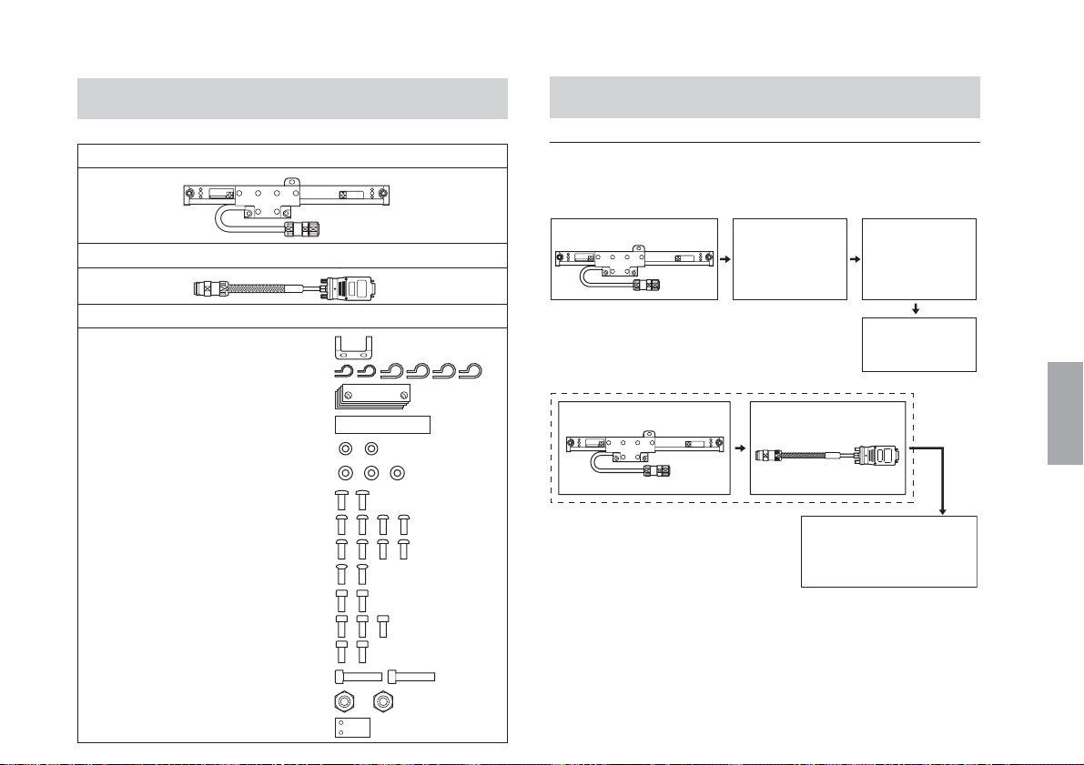
1-3. Anordnung der Teile
1-4. Systemaufbau
Maßstabseinheit ................................................................ 1
Anschlusskabel (CH04: gehört nur bei der Serie GB-ER zur Ausstattung) .....
Mitgeliefertes Zubehör
Klemme ......................................... 1
Kabelklemmens .... (2 klein, 4 groß)
Abstandsstücke ............................. 5
Blendenaufkleber .......................... 1
Unterlegscheiben (klein) ............... 2
Unterlegscheiben (mittelgroß) ...... 3
+B4×10 .......................................... 2
+P4×5 ............................................ 4
+P4×10 .......................................... 4
+K3×5 ............................................ 2
HSB M4×8 ..................................... 2
HSB M4×10 ................................... 3
HSB M4×12 ................................... 2
HSB M5×25 ................................... 2
Muttern (M5).................................. 2
Sicherungsplatte ........................... 1
Systemanschlüsse
• Serie SR138R
Maßstabseinheit
1
Verlängerungskabel
(Sonderzubehör)
• Serie GB-ER
Maßstabseinheit (SR138R)
Anschlusskabel
(CH04-03C)
Anschlusskabel
(Sonderzubehör)
Anzeigeeinheit
(Sonderzubehör)
CH01-**C
COMBINATION No.
******
MADE IN JAPAN
Anzeigeeinheit Serie
LH70/71 usw.,
Steuergerät
(Sonderzubehör)
(G
Deutsch
) 3

Deutsch
Modellreihe (Serie SR138R)
Modellname
SR138-005R
SR138-010R
SR138-015R
SR138-020R
SR138-025R
SR138-030R
SR138-035R
SR138-040R
SR138-045R
SR138-050R
SR138-055R
SR138-060R
SR138-065R
SR138-075R
SR138-085R
SR138-095R
SR138-105R
SR138-125R
SR138-140R
SR138-160R
SR138-185R
SR138-205R
SR138-220R
Messlänge
(L)
50 mm
100 mm
150 mm
200 mm
250 mm
300 mm
350 mm
400 mm
450 mm
500 mm
550 mm
600 mm
650 mm
750 mm
850 mm
950 mm
1050 mm
1250 mm
1400 mm
1600 mm
1850 mm
2050 mm
2200 mm
Mittelfuß
Ohne
Inbegriffen
Modellreihe (Serie GB-ER)
Modellname Mittelfuß
GB-005ER
GB-010ER
GB-015ER
GB-020ER
GB-025ER
GB-030ER
GB-035ER
GB-040ER
GB-045ER
GB-050ER
GB-055ER
GB-060ER
GB-065ER
GB-075ER
GB-085ER
GB-095ER
GB-105ER
GB-125ER
GB-140ER
GB-160ER
GB-185ER
GB-205ER
GB-220ER
SR138-005R
SR138-010R
SR138-015R
SR138-020R
SR138-025R
SR138-030R
SR138-035R
SR138-040R
SR138-045R
SR138-050R
SR138-055R
SR138-060R
SR138-065R
SR138-075R
SR138-085R
SR138-095R
SR138-105R
SR138-125R
SR138-140R
SR138-160R
SR138-185R
SR138-205R
SR138-220R
Messlänge
(L)
50 mm
100 mm
150 mm
200 mm
250 mm
300 mm
350 mm
400 mm
450 mm
500 mm
550 mm
600 mm
650 mm
750 mm
850 mm
950 mm
1050 mm
1250 mm
1400 mm
1600 mm
1850 mm
2050 mm
2200 mm
Ohne
Inbegriffen
Anschlusskabellänge
Modellname
CH04-03C
Kabellänge
3 m
4
(G)
 Loading...