

Magnescale SQ10 SERIES Instruction Manual

Instruction Manual
Scale
SQ10
Series
Notes
•
Take adequate care not to fold or bend the cables when using this product.
•
Do not install equipment that generates strong magnetic waves in the vicinity of this product.
•
Use this product in an environment having an ambient temperature range of 0 °C to +50 °C and that is not directly exposed
to sunlight or heat sources.
•
Avoid touching other scales or other parts of the scale with this product.
•
Do not attempt to reinstall this product.
•
Make sure that the external magnetic eld does not exceed 0.5 mT.
Read all the instructions in the manual carefully before use and strictly follow them.
Keep the manual for future references.
2015.12
Printed in Japan
©2015 Magnescale Co., Ltd.
SQ10 Series
2-A01-946-1A
45 Suzukawa, Isehara-shi, Kanagawa 259-1146, Japan
日本からの輸出時における注意
本製品 ( および技術 ) は輸出令別表第1の16の項(外為令別表 16 の項 ) に該当します。キャッチオー
ル規制による経済産業省の許可要否につきましては、輸出者様にてご確認ください。
For foreign customers
Note: is product (or technology) may be restricted by the government in your country. Please make sure
that end-use, end user and country of destination of this product do not violate your local government
regulation.
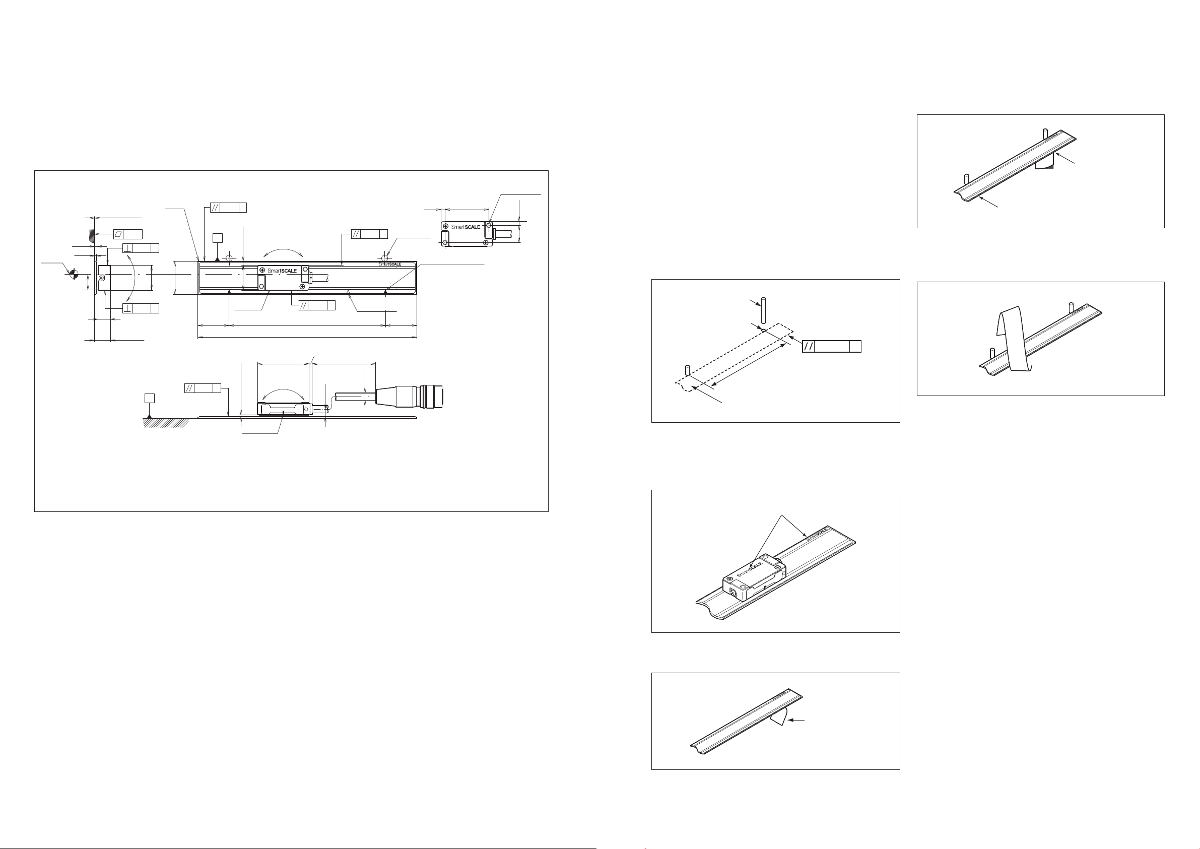
6. A x the scale while making contact with two or more
parallel pins.
Using your ngers, x the scale in place by rmly pressing
down the 30-mm section of the peeled backing paper.
7. Pe el o the backing paper to the position where the next
parallel pin is reached.
8. A x the scale while making contact with the parallel pin
and being careful that rm contact is maintained.
9. Repeat steps 7 and 8 until the entire length of the scale is
a xed.
10. Press down the entire length of the scale with your
ngers.
Installation Procedure
Preparation
Make holes on the scale installation surface for inserting
parallel pins so that positioning can be performed.
•
e parallelism of the holes with respect to the machine
guide should be 50 μm or less. (See the Installation
Dimensional Diagram.)
Installation
1. Leave the scale near the machine where it will be installed
for one hour so that the scale can adjust to the machine
temperature.
2. Use a clean cloth dipped in alcohol to wipe o any dirt,
dust or oil from the installation surface.
3. Insert the parallel pins.
4. Check the orientation of the scale. Aligh the scale so that
the SmartSCALE marks on the scale and head are facing
in the same direction.
5. Peel o about 30 mm of the backing paper.
Peel o about 30 mm
Peel o to the position where
the next parallel pin is reached
Speci cations
Operating temperature range : 0 to 50 °C
Storage temperature range : –20 to 60 °C
Mass : (E ective length × 0.22) + 8 g
Installation Dimensional Diagram
Align the SmartSCALE mark on the scale and head so that they are facing the same direction.
M : Machine guide
0.05
M
B
Head unit
20 (20)
0.05 A
Yaw: ±0.5°
2.5±0.8
Oset
(16)
Total length = Eective length + 40
Pich: ±0.3°
0.185±0.1
Clearance
Center mark
Measurement
detection
position
0.145
(Double-sided tape thickness)
1.2
1
10.5
0.05
0.04
Roll:
±0.3°
8
0.04 A
(9.385)
SQ10
Scale
A
21
16
A
Eective length
33
2
B0.28
Cable length
3.9
B0.28
Reference point
position mark
I4.7
2.5
Parallel pin
Eective length mark
28
Unit : mm
2 × M3 depth6
2.5
11
Parallel pin
Parallel pin
insertion hole
0.05 M
1000 mm or less
Scale installation surface
M: Machine guide
Make contact
Make contact
SmartSCALE marks
Backing paper
 Loading...