


Scale Unit / Maßstabseinheit /
SJ300 Series
Read all the instructions in the manual carefully before use and strictly follow them.
Keep the manual for future references.
Lesen Sie die ganze Anleitung vor dem Betrieb aufmerksam durch und folgen Sie
beim Betrieb des Geräts den Anweisungen. Bewahren Sie diese Bedienungsanleitung
zum späteren Nachlesen griffbereit auf.
Instruction Manual / Bedienungsanleitung /

[For U.S.A. and Canada]
[ For EU and EFTA countries ]
THIS CLASS A DIGITAL DEVICE
COMPLIES WITH PART15 OF THE
FCC RULES AND THE CANADIAN
ICES-003. OPERATION IS
SUBJECT TO THE FOLLOWING
TWO CONDITIONS.
(1) THIS DEVICE MAY NOT
CAUSE HARMFUL
INTERFERENCE, AND
(2) THIS DEVICE MUST ACCEPT
ANY INTERFERENCE
RECEIVED, INCLUDING
INTERFERENCE THAT
MAY CAUSE UNDERSIGNED
OPERATION.
CET APPAREIL NUMERIQUE DE
LA CLASSE A EST CONFORME A
LA NORME NMB-003 DU CANADA.
[For the customers in Australia]
Australian EMC Notice
This product complies with the
following Australian EMC standards.
AS/NZS 4252.1 /94 EMC Generic
Immunity Part1
AS/NZS 2064 /92 Emission
Standard for ISM Equipment
CE Notice
Marking by the symbol CE indicates
compliance with the EMC directive of
the European Community. This
marking shows conformity to the
following technical standards.
EN 55011 Group 1 Class A / 98 :
"Limits and methods of
measurement of radio
disturbance characteristics of
industrial, scientific and medical
(ISM) radio-frequency
equipment"
EN 61000-6-2 / 99 :
"Electromagnetic compatibility
(EMC) - Part 6-2 : Generic
standards - Immunity for
industrial environments"
警告
本装置を機械指令(EN60204-1)の適
合を受ける機器にご使用の場合は、
その規格に適合するように方策を講
じてから、ご使用ください。
Warning
When using this device with
equipment governed by Machine
Directives EN 60204-1, measures
should be taken to ensure
conformance with those directives.
Warnung
Wenn dieses Gerät mit
Ausrüstungsteilen verwendet wird,
die von den Maschinenrichtlinien EN
60204-1 geregelt werden, müssen
Maßnahmen ergriffen werden, um
eine Übereinstimmung mit diesen
Normen zu gewährleisten.
Safety Precautions
Magnescale Co., Ltd. products are designed in full consideration of safety. However, improper
handling during operation or installation is dangerous and may lead to fire, electric shock or
other accidents resulting in serious injury or death. In addition, these actions may also worsen
machine performance.
Therefore, be sure to observe the following safety precautions in order to prevent these types
of accidents, and to read these “Safety Precautions” before operating, installing, maintaining, inspecting, repairing or otherwise working on this unit.
Warning Indication Meanings
The following indications are used throughout this manual, and their contents should be
understood before reading the text.
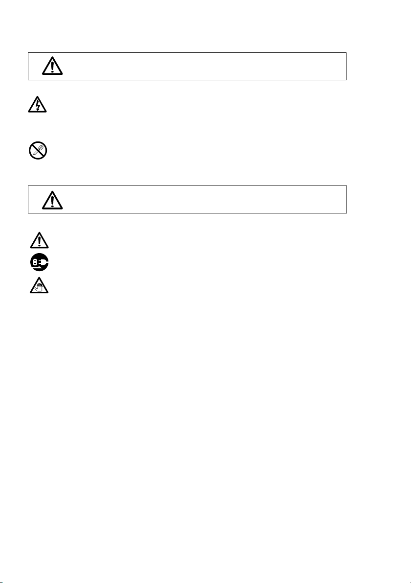
Warning
Failure to observe these precautions may lead to fire, electric shock or other accidents resulting in serious injury or death.
Caution
Failure to observe these precautions may lead to electric shock or other accidents resulting
in injury or damage to surrounding objects.
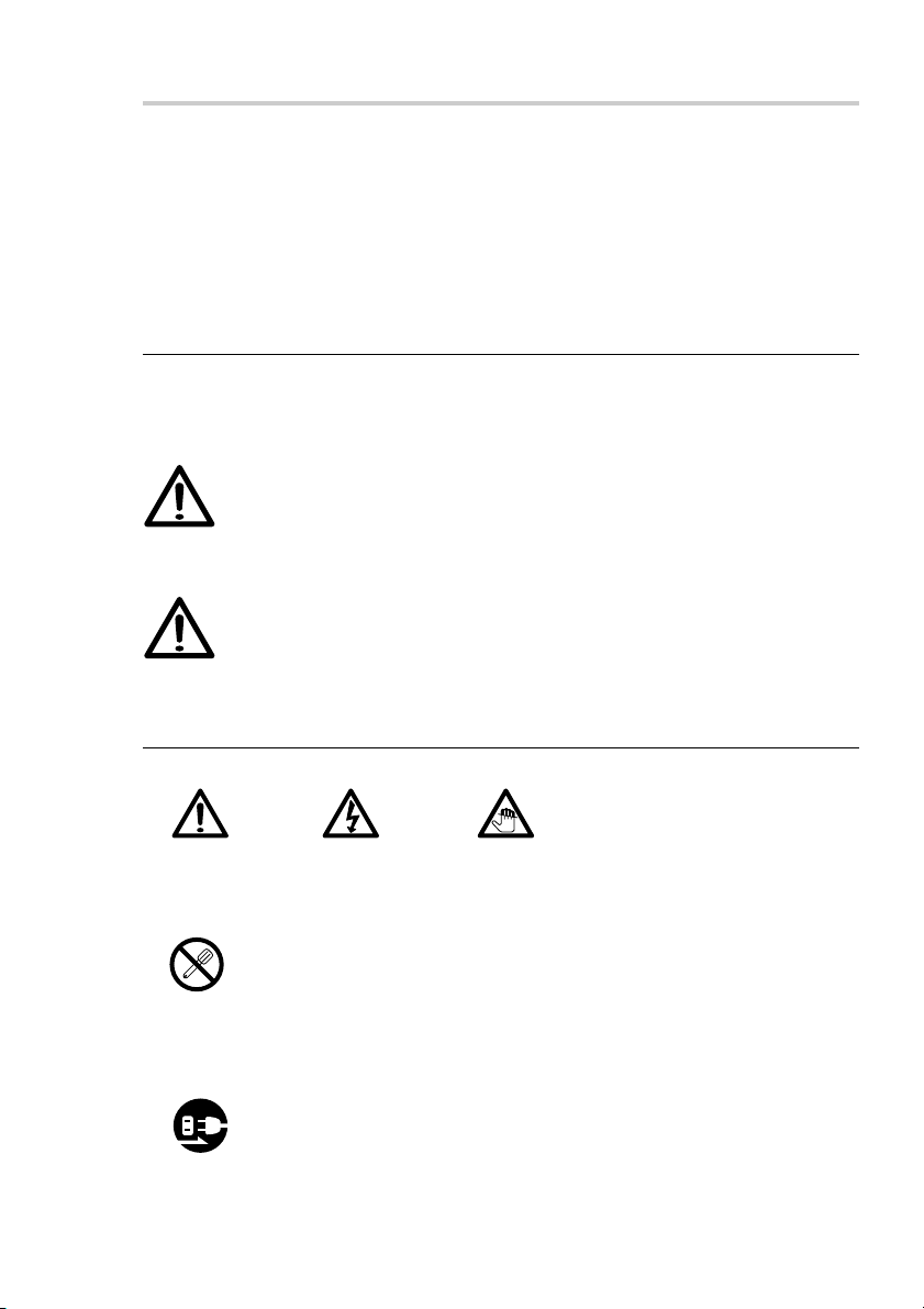
Symbols requiring attention
CAUTION ELECTRICAL
SHOCK
Symbols prohibiting actions
DO NOT
DISASSEMBLE
Symblos specifying actions
UNPLUGGING
SJ300 Series
FINGER
JAM
(E) (1)
Warning
• Do not use this unit with voltages other than the specified supply voltage as this
may result in fire or electric shock.
• Do not perform installation work with wet hands as this may result in electric
shock.
• Do not disassemble or modify the unit as this may result in injury or damage the
internal circuits.
Caution
• Be sure to check the machine and device conditions to ensure work safety before
working on the machine.
• Be sure to cut off the power supply and other sources of drive power before installing the working on the machine. Failure to do so may result in fire or accidents.
• When turning on the power supply, etc. to operate the machine, take care not to
catch your fingers in peripheral machines and devices.
(2) (E)
SJ300 Series

Handling Precautions
Installation precautions
When installing this unit, care should be given to the following points to prevent noise and
electromagnetic wave interference from other equipment.
1. Do not pass lead and connection cables through the same ducts as power lines.
2. Be sure to install the unit at least 0.5 m/1.6 ft or more away from high voltage or large
current sources or high-power relays.
3. Absolutely do not bring the unit near magnets or sources of electromagnetic waves.
• Magnet chucks and other sources of magnetic force of approx. 60 mT should be kept
at least 50 mm/2.0 in or more away from the shaft scale surface.
• If the unit must be installed close to sources of magnetic force, be sure to implement
adequate electromagnetic shielding countermeasures.
Installation place precautions
1. Mount the scale for more precise positioning as closely as possible to the workpiece or
to the object being measured.
(The farther the scale is mounted from workpiece, the greater the mechanical errors
grow.)
2. The scale unit should be used within an ambient temperature range of 0 to 40°C (104F°).
Avoid locations where the scale is exposed to direct sunlight and heat sources such as
motors.
3. Do not place anything on the mounted scale, or step on it: excessive force to the scale
causes trouble.
SJ300 Series
(E) (3)

Precautions for use under the following environments
1. When using water-miscible cutting fluid or when cutting non-metal
(ceramic, glass fiber, etc.) objects.
• Mount the scale so that it is not directly exposed to water-miscible cutting fluid or cutting
scraps.
• Attach a scale cover to prevent water-miscible cutting fluid mist or powder from entering
the inside of the scale.
2. When mounted on a forming machine or other machine that slides at
high speed for long periods within a specific area.
• Regularly apply oil or spray lubricant (CRC, WD40, etc.).
Be sure to implement the above measures when using the scale under the environments
noted in 1 and 2 above. Otherwise, quality cannot be assured.
General Precautions
When using Magnescale Co., Ltd. products, observe the following general precautions along
with those given specifically in this manual to ensure proper use of the products.
• Before and during operations, be sure to check that our products function properly.
• Provide adequate safety measures to prevent damage in case our products should develop
a malfunction.
• Use outside indicated specifications or purposes and modification of our products will
void any warranty of the functions and performance as specified for our products.
• When using our products in combination with other equipment, the functions and
performance as noted in this manual may not be attained, depending upon the operating
environmental conditions. Make a thorough study of the compatibility in advance.
(4) (E)
SJ300 Series

Contents
1. Overview .................................................................... 1
1-1. Introduction ....................................................................................................... 1
1-2. Main Features ................................................................................................... 1
1-3. Product Configuration ....................................................................................... 1
1-4. System Configuration ....................................................................................... 2
2. Name and Function of Each Part .............................3
2-1. Scale ..................................................................................................................3
2-2. Cable (sold separately: CH33-
3. Mounting ....................................................................5
3-1. Mounting precautions ....................................................................................... 5
3-1-1. Mounting locations ........................................................................5
3-1-2. Other Precautions ...........................................................................6
3-2. Mounting Procedure ......................................................................................... 8
4. Specifications .......................................................... 13
4-1. Scale ................................................................................................................13
4-2. Cable ............................................................................................................... 14
CPD/CED) ..................................................4
**
5. Dimensions .............................................................. 15
SJ300 Series
(E) i

ii (E)
SJ300 Series

1. Overview
1-1. Introduction
• The SJ300 series is a lineup of linear scales featuring self-adjusting reader head and a
shaft-type magnetic scale.
• A dedicated output cable (CH33output cable can be selected by the user. (Maximum cable length: 15 m/49.2 ft)
1-2. Main Features
Easy mounting
The head with self-adjusting reader head and dedicated scale bracket with wide allowable
mounting range enable the scale to be mounted in significantly less time.
No electrical adjustments
All electrical circuits, including interpolation circuits, are incorporated into the slider so that
no electrical adjustments are needed when changing the cable length or mounting the scale.
Resistant to oil and dust
The magnetic scale uses an exclusive Magnescale Co., Ltd. design for providing a structure
that is resistant to oil and dust.
CPD/CED) is sold separately. The length of the
**
1-3. Product Configuration
Scale Shaft scale............................................................................................. 1
Head ...................................................................................................... 1
Accessories Scale bracket 1 set
Scale brackets A, B, C ......................................................2 each
Hexagonal bolts M5×20 ............................................................ 6
Hexagonal nuts M5 ................................................................... 6
Flat washers W8 ....................................................................... 4
For securing scale head and cable
Cable clamp (small) .................................................................. 1
Cable clamps (large) ................................................................. 4
HSB M4×15 .............................................................................. 7
HSB M4×25 .............................................................................. 2
HSB M6×25 .............................................................................. 2
SJ300 Series
(E) 1
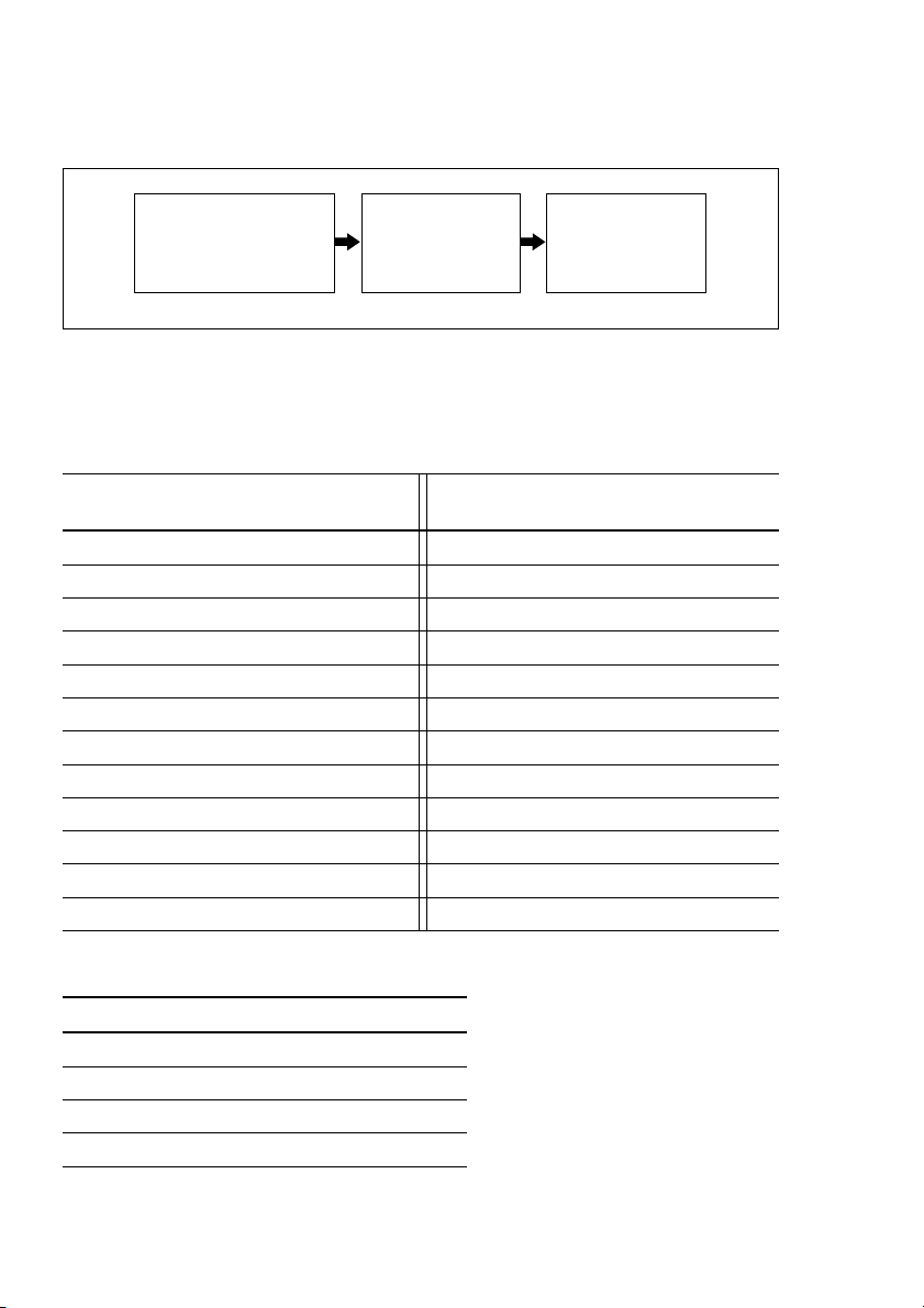
1-4. System Configuration
Scale
SJ300 series
Connecting cable
(sold separately)
CH33-
**
CPD/CED
Counter unit
(sold separately)
LH70/LH71 series
Model Configuration
Scale
Model name Measuring length (ML) Model name Measuring length (ML)
SJ300-005 50/1.9" SJ300-065 650/25.5"
SJ300-010 100/3.9" SJ300-075 750/29.5"
SJ300-015 150/5.9" SJ300-080 800/31.4"
SJ300-020 200/7.8" SJ300-085 850/33.4"
SJ300-025 250/9.8" SJ300-095 950/37.4"
SJ300-030 300/11.8" SJ300-105 1050/41.3"
SJ300-035 350/13.7" SJ300-125 1250/49.2"
SJ300-040 400/15.7" SJ300-140 1400/55.1"
SJ300-045 450/17.7" SJ300-160 1600/62.9"
SJ300-050 500/19.6" SJ300-185 1850/72.8"
SJ300-055 550/21.6" SJ300-205 2050/80.7"
SJ300-060 600/23.6" SJ300-220 2200/86.6"
(mm/inch) (mm/inch)
Connecting cable (sold separately)
Model name Cable length (m/ft)
CH33-03CPD/CED 3/9.8'
CH33-05CPD/CED 5/16.4'
CH33-10CPD/CED 10/32.8'
CH33-15CPD/CED 15/49.2'
2 (E)
SJ300 Series
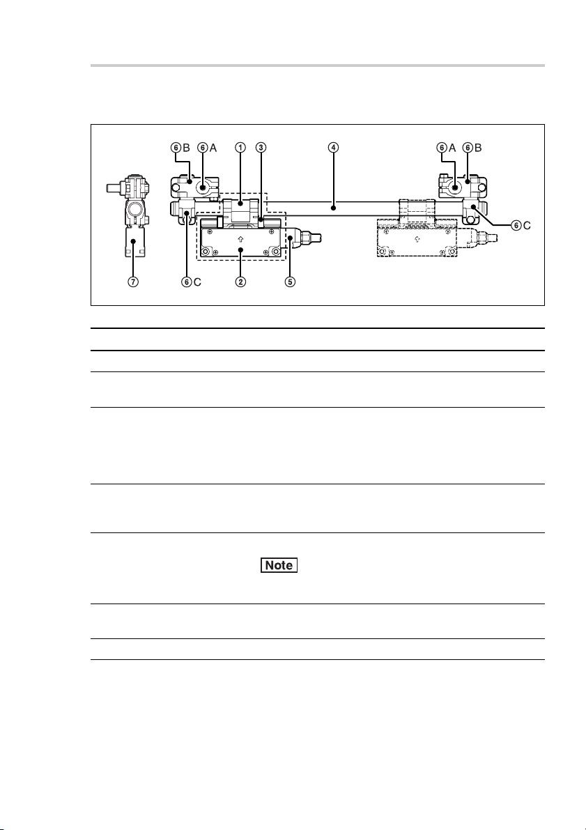
2. Name and Function of Each Part
2-1. Scale
Head
No. Name Function
1 Head holder Includes built-in detector sensor using MR element.
2 Slider This receives signals from the head and includes a circuit
for generating A/B quadrature signals.
3 Holder bracket Secures the head holder and slider. This prevents
4 Shaft scale The structure has an internal magnetic band for magnetic
5 Cable connector Connects the cable.
unnecessary force from being applied to the head holder
during installation. It serves as a rough guide for head
and scale installation, and so do not remove it until scale
mounting is completed.
recording. The outer surface has a stainless steel pipe
structure that also provides protection.
Do not apply excessive pressure to the connector pins.
This can cause them to break.
6 Scale brackets These brackets are used to mount the shaft scale.
A, B, and C There are three types: A, B, and C.
7 Status lamp This is a lamp for checking the scale mounting.
SJ300 Series
(E) 3
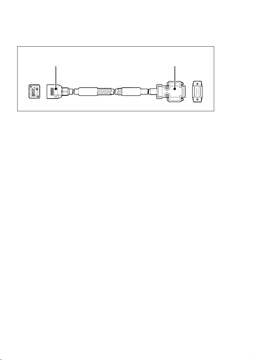
2-2. Cable (sold separately: CH33-**CPD/CED)
Input connector
(SJ300 side)
Output connector
(Counter unit side)
4 (E)
SJ300 Series
3. Mounting
3-1. Mounting precautions
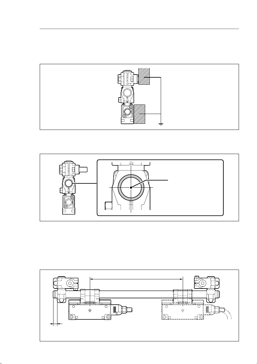
To prevent problems due to noise, mount the scale and slider so that they are connected to
the machine ground.
3-1-1. Mounting locations
Shaft scale and head holder locational relationship
Center offset:
±0.5 mm/0.02 in or less
Head holder center and
shaft scale during mounting
Head movable range
Be sure that the measurement length (ML) is within the value shown in “5. Dimensions.”
Mounting when the head movable range exceeds the scale maximum
operating length
Be sure to implement mechanical limiting mechanisms (such as stoppers).
ML
9±3 mm
/0.35"±0.12"
SJ300 Series
Do not mount the scale bracket any further
inside from here (head side).
(E) 5
Where the scale is exposed to chips and cutting oil
It is recommended a protective cover as shown in the figure be provided to maintain the
scale’s high performance.
3-1-2. Other Precautions
• Do not disassemble.
• Do not apply excessive pressure or try to bend the scale or head.
6 (E)
SJ300 Series
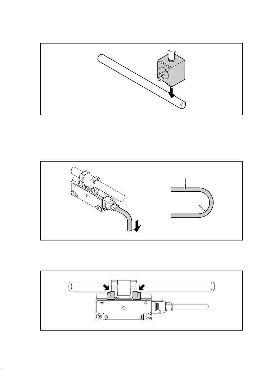
• Do not bring magnet chucks or other strong magnetic sources near the scale.
• Do not pull strongly or put excessive pressure on the cable.
Bending radius: Cable moving part: r = 50 mm/2.0"
<When cable is secured>
Cable part: r = 20 mm/0.8", Armored cable part: r = 25 mm/1.0"
Cable
Bending radius : r
• To protect the head holder, do not remove the holder brackets until scale mounting is
complete.
SJ300 Series
(E) 7
3-2. Mounting Procedure
This section describes the standard mounting procedure for mounting with reference to the
head. This is an effective mounting method when the scale mounting surface has a casting
surface finish.
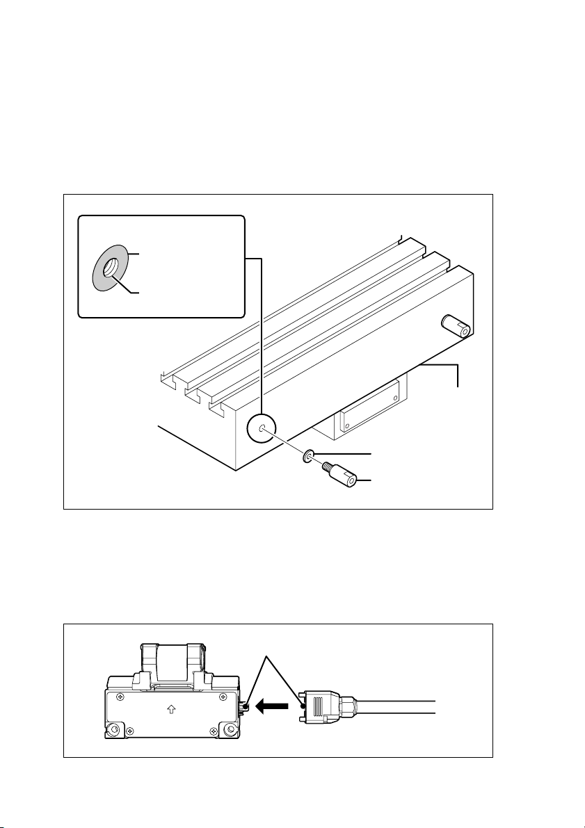
1. Mounting scale bracket A
Be sure to maintain flatness of the mounting surface within the range below.
Refer to “5. Dimensions” for the mounting location.
Diameter:
16 mm/0.63" or more
Flatness:
0.1 mm/0.004" or less
Tap hole M8 depth:
15 mm/0.59" or more
Tab le
Flat washer
Scale bracket A
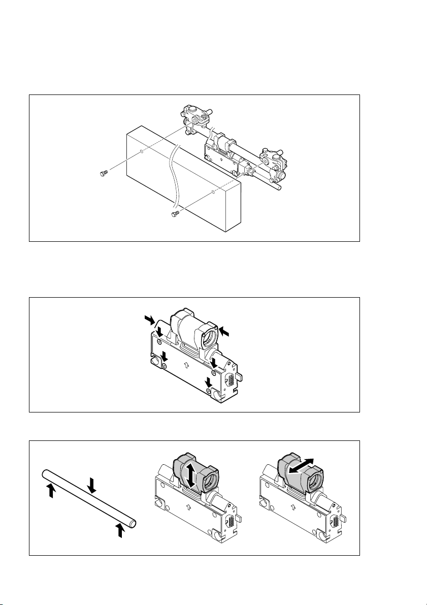
2. Securing the cable
Check that the scale power supply is turned off, and then connect the cable to the
slider. When connecting, be careful that the connector pin does not get bent.
(Connector set screw M2.6: Tightening torque: 0.3 N
•
m)
After connecting the cable, be careful that no force is applied to it.
Align the guide
8 (E)
SJ300 Series
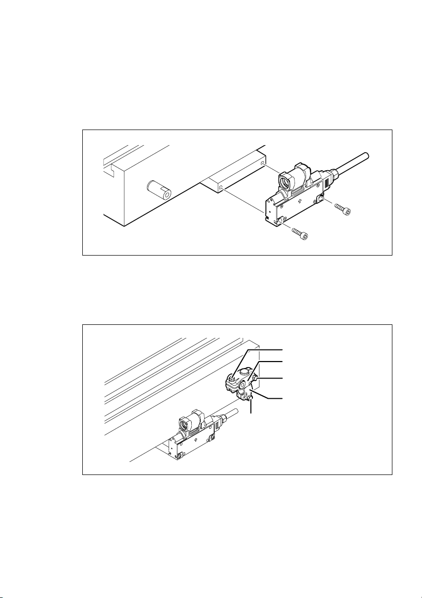
3. Mounting the head
Refer to “5. Dimensions” for the mounting location. The slider can be mounted on
either side, and so mount it based on the direction that the cable is pulled out during
operation.
Mounting parallelism: 0.1 mm/0.004"
Tightening torque: 2.7 N
•
m
4. Mounting the scale brackets B and C
Attach the hexagonal bolts and hexagonal nuts to the scale brackets B and C on either
the right or left side, and assemble as shown in the figure. When attaching, temporarily
tighten hexagonal bolts 1, 2, and 3 so that the brackets will not fall off.
Hexagonal bolt 1
Scale bracket B
Hexagonal bolt 2
Scale bracket C
Hexagonal bolt 3
5. Mounting the scale brackets B and C on the opposite side
In the same way as step 4, assemble scale brackets B and C on the other side.
SJ300 Series
(E) 9
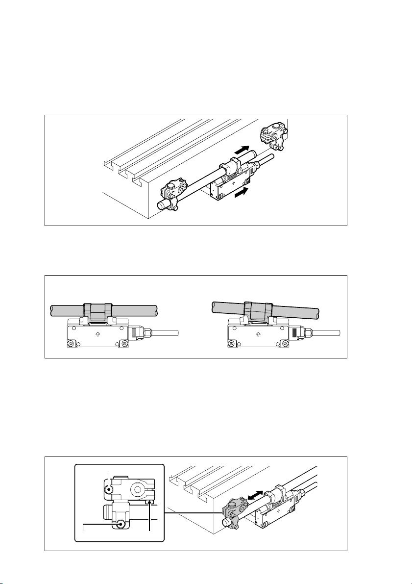
6. Pass through the shaft scale
Move the table so that the head is near either the right or left scale bracket, and then
pass the shaft scale through the head and scale bracket.
If the shaft scale cannot be inserted, loosen the hexagonal bolts 1, 2, and 3 enough
so that it can fit through.
7. Temporarily tighten hexagonal bolts 1, 2, and 3
Gently tighten hexagonal bolts 1, 2, and 3 in that order while being careful not to
apply pressure to the head holder.
NGOK
Not parallel
to slider
Move the table so that the head is near the scale bracket on the opposite side, and then
gently tighten the hexagonal bolts 1, 2, and 3, in that order, in the same way.
8. Tighten hexagonal bolts 1 and 2
Loosen hexagonal bolt 3, and then tighten hexagonal bolts 1 and 2 using the same
procedure as step 7 while confirming that the shaft scale moves smoothly to the left and
right. Repeatedly move the table, and tighten the bolts gradually in an alternating fashion.
Tightening torque: 5.4 N
Tighten
Hexagon bolt 3
•
m
Tighten
10 (E)
SJ300 Series
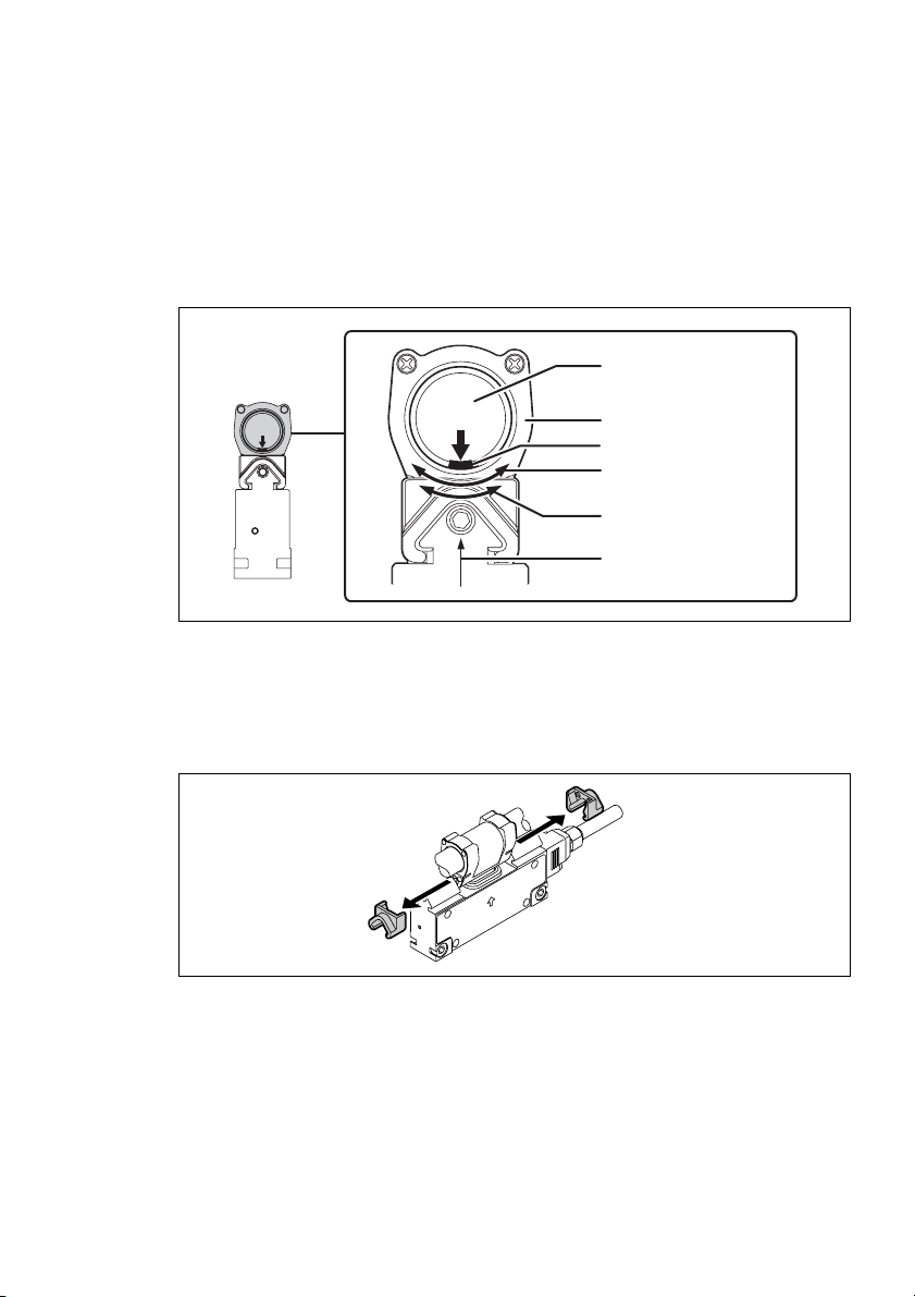
9. Securing the shaft scale
Determine the shaft scale position. To obtain stable signals, rotate and position the shaft
scale so that the head and shaft scale have the positional relationship shown in the
figure.
As shown in the figure, magnetic recording in the shaft scale is possible only for a
range of approximately 70 degrees (9 mm/0.35") in the circumferential direction. Note
that signals cannot be detected for positions that are not recorded magnetically.
Shaft scale
Head holder
Scale position mark
Scale recording
range: 9 mm/0.35"
Recommended
setting range: 3 mm/0.12"
Detector sensor
Tighten the hexagonal bolts 3 on both ends.
Tightening torque: 5.4 N
•
m
10. Removing the holder bracket
Pull the holder brackets to the right and left to remove.
11. Connecting the cable and counter unit
Connect the dedicated cable CH33-
CPD/CED directly to the counter unit LH70/
**
LH71 (set screws: inch type). The cable has a pin layout enabling direct connection to
the counter unit.
12. Turning on the power
Turn on the power of the counter unit LH70/LH71.
SJ300 Series
(E) 11

13. Post-mounting check
Check that status lamp lights green and the count values are displayed properly over the
entire measuring length.
When the status lamp is turned off:
• Check the power voltage of the LH70/LH71.
• Check that the cable is not disconnected, only cables designated by Magnescale
Co., Ltd. are being used, and no cable extensions exceed the stipulated limit.
When the status lamp is lit red:
•Return to step 9, “Securing the shaft scale,” and check mounting again.
If the status lamp does not light green after checking the points above or the scale does
not count normally, contact the Customer service section.
12 (E)
SJ300 Series
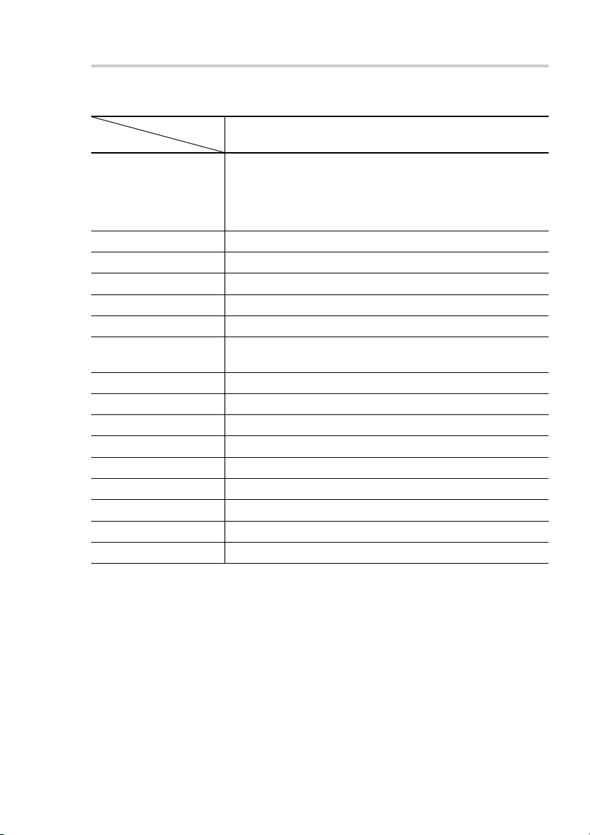
4. Specifications
4-1. Scale
Item
Measuring length 50/1.9", 100/3.9", 150/5.9", 200/7.8", 250/9.8", 300/11.8",
(mm/inch) 350/13.7", 400/15.7", 450/17.7", 500/19.6", 550/21.6",
Expansion coefficient (12 ±1) x10-6 / °C
Output signal A/B quadrature (compliant with EIA-422)
Min. phase difference 200 ns
Accuracy (20°C/68°F) ±10 µm/m
Resolution 1 µm
Alarm function -
Power supply voltage 5 Vdc ±5 %
Power consumption 2.5 W or less (Terminated 130 Ω load)
Operating temperature 0 to 45°C (32 to 113°F)
Storage temperature –20 to 60°C (–4 to 140°F)
Max. response speed 60 m/min
Vibration resistance 20 m/s2 , 50 Hz to 2 kHz
Shock resistance 600 m/s2, 11 ms
Protective design grade IP64 (Or equivalent)
Outside dimension Refer to Chapter 5.
Model name SJ300-005 to 220
600/23.6", 650/25.5", 750/29.5", 800/31.4", 850/33.4",
950/37.4", 1050/41.3", 1250/49.2", 1400/55.1", 1600/62.9",
1850/72.8", 2050/80.7", 2200/86.6"
NOTE
Exceed max. response speed, Drop in scale signal output level:
A/B quadrature signal becomes high impedance.
NOTE
• The scale travel is detected in 200 ns increments and output at a phase difference
proportionate to the amount traveled.
• The phase difference changes in integral multiples of 200 ns.
• When the scale has following condition, A/B signal are placed in the high impedance status.
• Phase difference of A and B signal is narrow than min phase difference time.
• Scale signal is small compare with specified value.
• Malfunctioning has occurred due to external noise or some other reason.
SJ300 Series
(E) 13
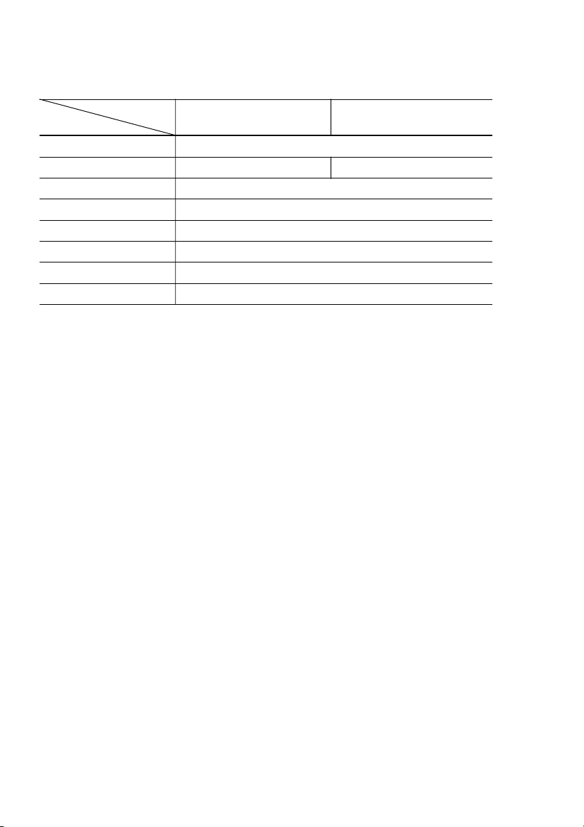
4-2. Cable
Model name CH33-**CPD CH33-**CED
Item
Configuration Armored cable with D-sub 9-pin connector
Cable sheath PVC Polyurethane
Cable armor YES
Cable length 3/9.8', 5/16.4', 10/32.8', 15/49.2' (m/ft)
Protective design grade IP65 (Scale side connector)
Operating temperature 0 to 45°C (32 to 113°F)
Storage temperature –20 to 60°C (–4 to 140°F)
Outside dimension Refer to Chapter 5.
14 (E)
SJ300 Series
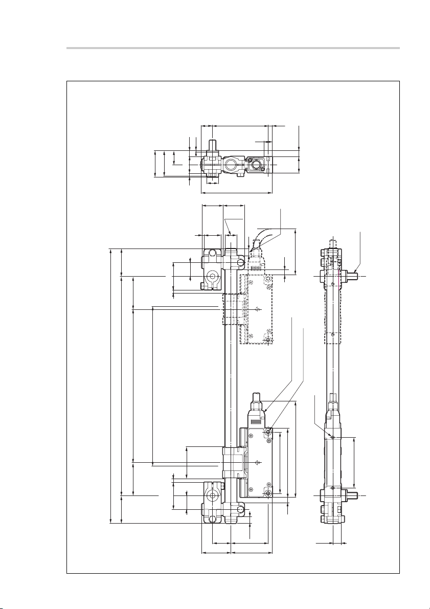
5. Dimensions
SJ300
34.5/1.36"
18.5/0.73"
33.5/1.32"
36/1.42"
43/1.69"
Measuring length = ML
Mounting pitch = ML + 86/3.39"
Overall length = ML + 158/6.22"
35.5/1.40"
(4.8/
0.19")
18/
7.5/0.30"
1.5/0.06"
22/0.87"
5/0.20"
3/0.12"
0.71 "
15/
0.59 "
1.10"
28/
0.87"
22/
72.5/2.85"
Ø15.1/0.59"
93/3.66"
1.08"
27.5/
0.59"
Ø15.1/
11/0.43"
0.22"
5.5/
8 ± 0.3/0.31" ± 0.01"
21/
0.83"
9 ± 3/0.35" ± 0.12"
(7/0.28")
(MIN 60/2.36")
CPD/CED
**
2-M6 (Ø5.0/0.20")
Cable: CH33-
(Sold separately)
Unit: mm/inch
M8 × 13.5/0.53"
2-M4 × 8/0.31"
SJ300 Series
Maximum operating length
= ML + 8/0.31" (4/0.16" each for left and right)
43/1.69"
36/1.42"
(4.8/
35.5/
0.19")
1.40"
18/
(41.4/1.63")
0.71"
24/0.94"
38/1.50"
9 ± 3/
0.35" ± 0.12"
48.5/1.91"
80/3.15"
54 ± 0.3/2.13" ± 0.02"
(125.5/4.94")
90/3.54"
(7/0.28")
66/2.60"
10.5/0.41"
(E) 15

ML : Measuring Length
Model name Measuring length Model name Measuring length
SJ300-005 50/1.9" SJ300-065 650/25.5"
SJ300-010 100/3.9" SJ300-075 750/29.5"
SJ300-015 150/5.9" SJ300-080 800/31.4"
SJ300-020 200/7.8" SJ300-085 850/33.4"
SJ300-025 250/9.8" SJ300-095 950/37.4"
SJ300-030 300/11.8" SJ300-105 1050/41.3"
SJ300-035 350/13.7" SJ300-125 1250/49.2"
SJ300-040 400/15.7" SJ300-140 1400/55.1"
SJ300-045 450/17.7" SJ300-160 1600/62.9"
SJ300-050 500/19.6" SJ300-185 1850/72.8"
SJ300-055 550/21.6" SJ300-205 2050/80.7"
SJ300-060 600/23.6" SJ300-220 2200/86.6"
(mm/inch) (mm/inch)
16 (E)
SJ300 Series

CH33-**CPD/CED
(17/0.67")
(21.6/0.85")
(35.5/1.40")
Scale connector
Cable length = 3/9.8', 5/16.4', 10/32.8', 15/49.2' (m/ft)
100/3.94"100/3.94"
Conduit
(Ø11.3/0.44")
(Ø8/0.31")
Model name Cable length : (m/ft)
PVC Polyurethane
CH33-03CPD CH33-03CED 3/9.8'
CH33-05CPD CH33-05CED 5/16.4'
CH33-10CPD CH33-10CED 10/32.8'
CH33-15CPD CH33-15CED 15/49.2'
(45/1.77")
D-sub 9-pin connector
(15/0.59")
Unit: mm/inch
(33/1.30")
SJ300 Series
(E) 17

18 (E)
SJ300 Series

Sicherheitsmaßnahmen
Bei dem Entwurf von Magnescale Co., Ltd. Produkten wird größter Wert auf die Sicherheit
gelegt. Unsachgemäße Handhabung während des Betriebs oder der Installation ist jedoch
gefährlich und kann zu Feuer, elektrischen Schlägen oder anderen Unfällen führen, die
schwere Verletzungen oder Tod zur Folge haben können. Darüber hinaus kann falsche
Behandlung die Leistung der Maschine verschlechtern.
Beachten Sie daher unbedingt die besonders hervorgehobenen Vorsichtshinweise in dieser
Bedienungsanleitung, um derartige Unfälle zu verhüten, und lesen Sie die folgenden
Sicherheitsmaßnahmen vor der Inbetriebnahme, Installation, Wartung, Inspektion oder
Reparatur dieses Gerätes oder der Durchführung anderer Arbeiten durch.
Bedeutung der Warnhinweise
Bei der Durchsicht dieses Handbuchs werden Sie auf die folgenden Hinweise und Symbole
stoßen. Machen Sie sich mit ihrer Bedeutung vertraut, bevor Sie den Text lesen.
Warnung
Eine Missachtung dieser Hinweise kann zu Feuer, elektrischen Schlägen oder anderen
Unfällen führen, die schwere Verletzungen oder Tod zur Folge haben können.
Vorsicht
Eine Missachtung dieser Hinweise kann zu elektrischen Schlägen oder anderen Unfällen
führen, die Verletzungen oder Sachbeschädigung der umliegenden Objekte zur Folge haben
können.
Zu beachtende Symbole
VORSICHT ELEKTRISCHER
SCHLAG
FINGERVERLETZUNG
Symbole, die Handlungen verbieten
NICHT
ZERLEGEN
Symbole, die Handlungen vorschreiben
STECKER
ABZIEHEN
SJ300 Series
(G) (1)

Warnung
• Betreiben Sie dieses Gerät nur mit der vorgeschriebenen Versorgungsspannung,
da anderenfalls die Gefahr von Feuer oder elektrischen Schlägen besteht.
• Führen Sie Installationsarbeiten nicht mit nassen Händen aus, da hierbei die Gefahr
elektrischer Schläge besonders groß ist.
• Unterlassen Sie jeden Versuch, das Gerät zu zerlegen oder umzubauen, da dies zu
Verletzungen oder Beschädigung der internen Schaltungen führen kann.
Vorsicht
• Überprüfen Sie vor Beginn der Installationsarbeiten unbedingt den Zustand von
Maschine und Vorrichtungen, um die Arbeitssicherheit zu gewährleisten.
• Schalten Sie vor Beginn der Installationsarbeiten an der Maschine unbedingt die
Stromzufuhr und andere Antriebsstromquellen aus. Anderenfalls besteht Brandoder Unfallgefahr.
• Achten Sie beim Einschalten der Stromversorgung usw. zum Betrieb der Maschine
darauf, dass Sie sich nicht die Finger in peripheren Maschinen und Vorrichtungen
klemmen.
(2) (G)
SJ300 Series

Hinweise zur Handhabung
Installationshinweise
Beachten Sie bei der Installation dieses Gerätes die folgenden Punkte, um die Einstreuung
von Rauschen und elektromagnetischen Wellen von anderen Geräten zu verhüten.
1. Verlegen Sie Zuleitungskabel und Verbindungskabel nicht zusammen mit
Starkstromkabeln.
2. Halten Sie bei der Installation des Gerätes mindestens 0,5 m Abstand von
Hochspannungs-, Starkstromquellen oder Hochleistungsrelais.
3. Bringen Sie das Gerät auf keinen Fall in die Nähe von Magneten oder Quellen
elektromagnetischer Wellen.
Hinweis
• Magnetische Futter oder andere Magnetkraftquellen von ungefähr 60 mT sollten
mindestens 50 mm von den Wellenmaßstabsflächen entfernt gehalten werden.
•Falls das Gerät in der Nähe von Magnetkraftquellen installiert werden muss, treffen
Sie unbedingt angemessene Maßnahmen zum Schutz vor elektromagnetischer
Beeinflussung.
Hinweise zum Installationsort
1. Um eine möglichst präzise Positionierung zu erzielen, empfiehlt es sich, den Maßstab
möglichst nahe am Werkstück oder zum messenden Objekt einzubauen. (Je weiter der
Maßstab vom Werkstück entfernt eingebaut wird, desto größer wird mechanische Fehler.)
2. Verwenden Sie die Skaleneinheit innerhalb eines Umgehungstemperaturbereiches von
0 bis 40°C. Einbauorte vermeiden, wo der Maßstab direkter Sonneneinstrahlung und
Wärmequellen, wie z.B. Motoren, ausgesetzt ist.
3. Nichts auf den angebauten Maßstab legen oder darauf treten: übermäßig starke
Einwirkung von Kräften auf den Maßstab erzeugt Störungen.
SJ300 Series
(G) (3)

Vorsichtsmaßnahmen zum Einsatz unter den folgenden
Umweltbedingungen
1 Bei Verwendung von wassermischbarer Schneidflüssigkeit, oder beim
Schneiden nichtmetallischer Objekte (Keramik, Glasfaser usw.).
• Den Maßstab so montieren, dass er nicht direkt wassermischbarer Schneidflüssigkeit
oder Spänen ausgesetzt ist.
• Eine Schutzhaube anbringen, um das Eindringen von wassermischbarem
Schneidflüssigkeitsnebel oder Staub in den Maßstab zu verhüten.
2 Bei Montage an einer Massivumformmaschine oder einer anderen
Maschine, die sich mit hoher Geschwindigkeit über lange Zeitspannen
innerhalb eines bestimmten Bereiches hin und her bewegt.
•Regelmäßig Öl oder Sprühschmiermittel (CRC, WD40, usw.) auftragen.
Ergreifen Sie unbedingt die obigen Maßnahmen, wenn der Maßstab unter den in den obigen
Punkten 1 und 2 beschriebenen Umweltbedingungen eingesetzt wird. Anderenfalls kann
keine Qualität gewährleistet werden.
Allgemeine Vorsichtsmaßnahmen
Beim Einsatz von Geräten von Magnescale Co., Ltd. sind die folgenden allgemeinen
Vorsichtsmaßnahmen zusätzlich zu den in der vorliegenden Anleitung jeweils speziell
angegebenen Warnhinweisen zu beachten, um einen korrekten Einsatz des Geräts zu
gewährleisten.
•Vor und während des Betriebs sicherstellen, dass das Gerät korrekt funktioniert.
• Geeignete Sicherheitsvorkehrungen zur Vermeidung von Schäden für den Fall ergreifen,
dass am Gerät eine Störung auftritt.
•Wird das Gerät außerhalb der angegebenen Spezifikationen und Einsatzzwecke verwendet
oder werden am Gerät Änderungen vorgenommen, kann keine Garantie für Funktion
und Leistung übernommen werden.
• Beim Einsatz des Geräts mit einem anderen nicht empfohlenen Gerät werden u.U. je
nach Betriebsbedingungen die in der vorliegenden Anleitung aufgeführten optimalen
Funktionen und Leistungen nicht erreicht. Daher die Kompatibilität im Voraus gründlich
prüfen.
(4) (G)
SJ300 Series

Inhaltsverzeichinis
1. Überblick .................................................................... 1
1-1. Vorwort ............................................................................................................. 1
1-2. Hauptmerkmale ................................................................................................. 1
1-3. Produktkonfiguration ........................................................................................ 1
1-4. Systemkonfiguration .........................................................................................2
2. Bezeichnungen und Funktionen der Teile .............. 3
2-1. Maßstab ............................................................................................................. 3
2-2. Kabel (getrennt erhältlich: CH33-
3. Montage ..................................................................... 5
3-1. Vorsichtsmaßnahmen zur Montage ...................................................................5
3-1-1. Montagestellen ...............................................................................5
3-1-2. Sonstige Vorsichtsmaßnahmen ...................................................... 6
3-2. Montageverfahren .............................................................................................8
4. Technische Daten.................................................... 13
4-1. Maßstab ........................................................................................................... 13
4-2. Kabel ...............................................................................................................14
5. Abmessungen .........................................................15
CPD/CED) ............................................ 4
**
SJ300 Series
(G) i

ii (G)
SJ300 Series

1. Überblick
1-1. Vorwort
• Bei den Modellen der Serie SJ300 handelt es sich um eine Reihe von Linearmaßstäben,
die einen selbstnachstellenden Lesekopf und einen magnetischen Maßstab in
Wellenausführung besitzen.
• Ein dediziertes Ausgangskabel (CH33-∗∗CPD/CED) ist getrennt erhältlich. Die Länge
des Ausgangskabels kann vom Benutzer gewählt werden. (Maximale Kabellänge: 15 m)
1-2. Hauptmerkmale
Einfache Montage
Der Kopf mit selbstnachstellendem Lesekopf und dediziertem Maßstabshalter mit breitem
zulässigen Montagebereich ermöglichen die Montage des Maßstabs in bedeutend kürzerer
Zeit.
Keine elektrischen Einstellungen
Alle elektrischen Schaltungen, einschließlich Interpolationsschaltungen, sind in den Schieber
integriert, sodass bei einer Änderung der Kabellänge oder der Montage des Maßstabs keine
elektrischen Einstellungen notwendig sind.
Öl- und staubbeständig
Dank des exklusiven Designs von Magnescale Co., Ltd. besitzt der magnetische Maßstab
eine öl- und staubbeständige Struktur.
1-3. Produktkonfiguration
Maßstab Wellenmaßstab ...................................................................................... 1
Kopf ....................................................................................................... 1
Zubehör Maßstabshalter 1 Satz
Maßstabshalter A, B, C..........................................................je 2
Sechskantschrauben M5×20 .................................................... 6
Sechskantmuttern M5 ............................................................... 6
Unterlegscheiben W8 ............................................................... 4
Zur Sicherung von Maßstabskopf und Kabel
Kabelklemme (klein) ................................................................. 1
Kabelklemmen (groß) ............................................................... 4
HSB M4×15 .............................................................................. 7
HSB M4×25 .............................................................................. 2
HSB M6×25 .............................................................................. 2
SJ300 Series
(G) 1

1-4. Systemkonfiguration
Maßstab
Serie SJ300
Anschlusskabel
(getrennt erhältlich)
CH33-
**
CPD/CED
Anzeigeeinheit
(getrennt erhältlich)
Serie LH70/LH71
Modellkonfiguration
Maßstab
Modellbezeichnung Messlänge (ML) (mm) Modellbezeichnung Messlänge (ML) (mm)
SJ300-005 50 SJ300-065 650
SJ300-010 100 SJ300-075 750
SJ300-015 150 SJ300-080 800
SJ300-020 200 SJ300-085 850
SJ300-025 250 SJ300-095 950
SJ300-030 300 SJ300-105 1050
SJ300-035 350 SJ300-125 1250
SJ300-040 400 SJ300-140 1400
SJ300-045 450 SJ300-160 1600
SJ300-050 500 SJ300-185 1850
SJ300-055 550 SJ300-205 2050
SJ300-060 600 SJ300-220 2200
Anschlusskabel (getrennt erhältlich)
Modellbezeichnung Kabellänge (m)
CH33-03CPD/CED 3
CH33-05CPD/CED 5
CH33-10CPD/CED 10
CH33-15CPD/CED 15
2 (G)
SJ300 Series

2.
Bezeichnungen und Funktionen der Teile
2-1. Maßstab
Kopf
Nr. Bezeichnung Funktion
1 Kopfhalter Enthält eingebauten Detektorsensor mit MR-Element.
2 Schieber Dieser empfängt Signale vom Kopf und enthält eine Schaltung
zur Erzeugung von A/B-Quadratursignalen.
3 Halterbügel Dient zur Sicherung von Kopfhalter und Schieber. Dieser Bügel
4 Wellenmaßstab Die Struktur weist ein internes Magnetband für
5 Kabelanschluss Hier wird das Kabel angeschlossen.
6 Maßstabshalter Diese Halter dienen zur Montage des Wellenmaßstabs.
A, B und C Es gibt drei Typen: A, B und C.
7 Statuslampe Diese Lampe dient zur Überprüfung der Maßstabsmontage.
verhindert, dass während der Installation eine unzulässige
Kraft auf den Kopfhalter einwirkt. Da er als grobe Führung für
die Installation von Kopf und Maßstab dient, sollte er erst nach
Abschluss der Maßstabsmontage entfernt werden.
Magnetaufzeichnung auf. Die Außenfläche besteht aus
einer Edelstahl-Rohrstruktur, die zusätzlichen Schutz bietet.
Hinweis
Üben Sie keinen übermäßigen Druck auf die
Anschlussstifte aus. Die Stifte können sonst abbrechen.
SJ300 Series
(G) 3

2-2. Kabel (getrennt erhältlich: CH33-**CPD/CED)
Eingangsanschluss
(SJ300-Seite)
Ausgangsanschluss
(Anzeigeeinheit-Seite)
4 (G)
SJ300 Series

3. Montage
3-1. Vorsichtsmaßnahmen zur Montage
Um auf Störeinstreuung zurückzuführende Probleme zu vermeiden, sind Maßstab und
Schieber so zu montieren, dass sie mit der Maschinenmasse verbunden sind.
3-1-1. Montagestellen
Lagebeziehung zwischen Wellenmaßstab und Kopfhalter
Mittenversatz:
maximal ±0,5 mm
Kopfhalter und Wellenmaßstab
während der Montage
Kopfbewegungsbereich
Ve rgewissern Sie sich, dass die Messlänge (ML) innerhalb des in „5. Abmessungen“
angegebenen Wertes liegt.
Montage, wenn der Kopfbewegungsbereich die Maximale Betriebslänge
des Maßstabs überschreitet
Wenden Sie unbedingt mechanische Begrenzungsmechanismen (wie z.B. Anschläge) an.
ML
9±3mm
SJ300 Series
Den Maßstabshalter ab hier (Kopfseite)
nicht weiter innen montieren.
(G) 5

Wenn der Maßstab Spänen und Schneidöl ausgesetzt ist
Es wird empfohlen, eine Schutzabdeckung anzubringen, wie in der Abbildung gezeigt, um
die hohe Leistung des Maßstabs aufrechtzuerhalten.
3-1-2. Sonstige Vorsichtsmaßnahmen
• Nicht zerlegen.
• Keinen übermäßigen Druck ausüben und nicht versuchen, Maßstab oder Kopf zu biegen.
6 (G)
SJ300 Series

• Keine Magnetfutter oder andere starke Magnetquellen in die Nähe des Maßstabs bringen.
• Das Kabel keiner übermäßigen Zug- oder Druckbelastung aussetzen.
Biegeradius : Kabelbewegungsteil: r = 50 mm
<Wenn das Kabel gesichert ist>
Kabelteil: r = 20 mm, bewehrter Kabelteil: r = 25 mm
Kabel
Biegeradius: r
• Um den Kopfhalter zu schützen, sind die Halterbügel erst nach Abschluss der
Maßstabsmontage zu entfernen.
SJ300 Series
(G) 7

3-2. Montageverfahren
Dieser Abschnitt beschreibt das Standard-Montageverfahren für Montage mit Bezug auf
den Kopf. Diese Montagemethode ist effektiv, wenn die Maßstab-Montagefläche eine
Gussoberfläche aufweist.
1. Montieren des Maßstabshalters A
Ve rgewissern Sie sich, dass die Ebenheit der Montagefläche innerhalb des unten
angegebenen Bereichs liegt.
Die Montageposition ist aus der Maßzeichnung in „5. Abmessungen“ ersichtlich.
Durchmesser:
16 mm oder mehr
Ebenheit:
0,1 mm oder weniger
Tiefe der
Gewindebohrung
M8: 15 mm oder mehr
Tisch
Unterlegscheibe
Maßstabshalter A
2. Sicherung des Kabels
Ve rgewissern Sie sich, dass die Stromversorgung des Maßstabs ausgeschaltet ist, bevor
Sie das Kabel an den Schieber anschließen. Achten Sie beim Anschließen darauf, dass
die Anschlussstifte nicht verbogen werden.
(Anschluss-Befestigungsschraube M2,6: Anzugsmoment: 0,3 N
•
m)
Achten Sie nach dem Anschluss des Kabels darauf, dass keine Kraft auf das Kabel
einwirkt.
Führung ausrichten
8 (G)
SJ300 Series

3. Montieren des Kopfes
Die Montageposition ist aus „5. Abmessungen“ ersichtlich. Da der Schieber auf beiden
Seiten montiert werden kann, montieren Sie ihn unter Berücksichtigung der Richtung,
in die das Kabel während des Betriebs herausgezogen wird.
Montageparallelität: 0,1 mm
Anzugsmoment: 2,7 N
•
m
4. Montieren der Maßstabshalter B und C
Die Sechskantschrauben und -muttern entweder auf der rechten oder linken Seite an
den Maßstabshaltern B und C anbringen, und die Montage gemäß der Abbildung
durchführen. Die Sechskantschrauben 1, 2 und 3 bei der Anbringung vorübergehend
anziehen, damit die Halter nicht herunterfallen.
Sechskantschraube 1
Maßstabshalter B
Sechskantschraube 2
Maßstabshalter C
Sechskantschraube 3
5. Montieren der Maßstabshalter B und C auf der gegenüberliegenden Seite
Montieren Sie die Maßstabshalter B und C auf die gleiche Weise wie in Schritt 4 auf der
anderen Seite.
SJ300 Series
(G) 9

6. Den Wellenmaßstab durchziehen
Den Tisch so verschieben, dass sich der Kopf in der Nähe des rechten oder linken
Maßstabshalters befindet, und dann den Wellenmaßstab durch Kopf und Maßstabshalter
ziehen.
Falls sich der Wellenmaßstab nicht einführen lässt, die Sechskantschrauben 1, 2 und
3 so weit lösen, dass er durchgezogen werden kann.
7. Die Sechskantschrauben 1, 2 und 3 vorübergehend anziehen
Die Sechskantschrauben 1, 2 und 3 in dieser Reihenfolge sachte anziehen, wobei
darauf zu achten ist, dass kein Druck auf den Kopfhalter ausgeübt wird.
NGOK
Nicht parallel
zum Schieber
Den Tisch verschieben, sodass sich der Kopf in der Nähe des Maßstabshalters auf der
gegenüberliegenden Seite befindet, und dann die Sechskantschrauben 1, 2 und 3 in
dieser Reihenfolge auf die gleiche Weise sachte anziehen.
8. Die Sechskantschrauben 1 und 2 anziehen
Die Sechskantschraube 3 lösen, und dann die Sechskantschrauben 1, 2 nach dem
in Schritt 7 angewandten Verfahren anziehen, während sichergestellt wird, dass sich der
Wellenmaßstab reibungslos nach links und rechts bewegt. Den Tisch wiederholt bewegen,
und die Schrauben nach und nach abwechselnd anziehen. Anzugsmoment: 5,4 N
Anziehen
Sechskantschraube 3
Anziehen
10 (G)
•
m
SJ300 Series

9. Sichern des Wellenmaßstabs
Legen Sie die Wellenmaßstabsposition fest. Um stabile Signale zu erhalten, ist der
We llenmaßstab so zu drehen und zu positionieren, dass Kopf und Wellenmaßstab die in
der Abbildung gezeigte Lagebeziehung zueinander haben.
Wie in der Abbildung gezeigt, ist die Magnetaufzeichnung im Wellenmaßstab nur für
einen Bereich von etwa 70 Grad (9 mm) in Umfangsrichtung möglich. Beachten Sie,
dass für Positionen, die nicht magnetisch aufgezeichnet werden, keine Signale erkannt
werden können.
Wellenmaßstab
Kopfhalter
Maßstabspositionsmarke
Maßstabsaufzeichnungsbereich:
9 mm
Empfohlener
Einstellbereich: 3 mm
Detektorsensor
Die Sechskantschrauben 3 an beiden Enden anziehen.
Anzugsmoment: 5,4 N
•
m
10. Entfernen des Halterbügels
Die Halterbügel nach rechts und links ziehen, um sie zu entfernen.
11. Anschließen des Kabels und der Anzeigeeinheit
Schließen Sie das dedizierte Kabel CH33-**CPD/CED direkt an die Anzeigeeinheit
LH70/LH71 an (Befestigungsschrauben: Zollgewinde). Die Stiftanordnung des Kabels
ermöglicht direkten Anschluss an die Anzeigeeinheit.
12. Einschalten der Stromversorgung
Schalten Sie die Stromversorgung der Anzeigeeinheit LH70/LH71 ein.
SJ300 Series
(G) 11

13. Überprüfung nach der Montage
Ve rgewissern Sie sich, dass die Statuslampe grün aufleuchtet und die Zählerwerte korrekt
über die gesamte Messlänge angezeigt werden.
Wenn die Statuslampe erloschen ist:
• Die Versorgungsspannung der Anzeigeeinheit LH70/LH71 überprüfen.
•Vergewissern Sie sich, dass das Kabel nicht abgetrennt ist, dass nur von Magnescale
Co., Ltd. vorgeschriebene Kabel verwendet werden, und dass die Kabelverlängerungen
nicht die vorgeschriebene Grenze überschreiten.
Wenn die Statuslampe rot leuchtet:
•Kehren Sie zu Schritt 9 „Sichern des Wellenmaßstabs“ zurück, und überprüfen Sie
die Montage erneut.
Falls die Statuslampe nach der Überprüfung der obigen Punkte nicht grün aufleuchtet
oder der Maßstab nicht normal zählt, wenden Sie sich an die Kundendienstabteilung.
12 (G)
SJ300 Series

4. Technische Daten
4-1. Maßstab
Posten
Modellbezeichnung
Messlänge (mm) 50, 100, 150, 200, 250, 300, 350, 400, 450, 500, 550,
Ausdehnungskoeffizient (12 ±1) × 10-6 / °C
Ausgangssignal A/B-Quadratur (entspricht EIA-422)
Min. Phasendifferenz 200 ns
Genauigkeit (20°C) ±10 µm/m
Auflösung 1 µm
Alarmfunktion - Überschreitung der max. Ansprechgeschwindigkeit
Versorgungsspannung 5 V Gleichstrom ±5 %
Leistungsaufnahme maximal 2,5 W (terminiert 130 Ω Last)
Betriebstemperatur 0 bis 45°C
Lagertemperatur –20 bis 60°C
Max. Ansprechgeschwindigkeit 60 m/min
Vibrationsfestigkeit 20 m/s2 , 50 Hz bis 2 kHz
Stoßfestigkeit 600 m/s2, 11 ms
Schutzklasse IP64 (oder Entsprechung)
Außenabmessungen Siehe Kapitel 5.
SJ300-005 bis 220
600, 650, 750, 800, 850, 950, 1050, 1250, 1400, 1600,
1850, 2050, 2200
HINWEIS
Abfall des Maßstab-Ausgangspegels:
A/B-Quadratursignal erhält hohe Impedanz.
HINWEIS
• Der Maßstab-Verfahrweg wird in 200-ns-Schritten erkannt und mit einer Phasendifferenz
proportional zum Bewegungsbetrag ausgegeben.
• Die Phasendifferenz ändert sich in ganzzahligen Vielfachen von 200 ns.
• Wenn sich der Maßstab in folgendem Zustand befindet, werden die A/B-Signale in den
Status der hohen Impedanz versetzt.
• Die Phasendifferenz der Signale A und B ist schmäler als die minimale Phasendifferenzzeit.
• Das Maßstabsignal ist klein im Vergleich zum angegebenen Wert.
• Eine Funktionsstörung ist wegen externer Störeinstreuung oder aus einem anderen Grund
aufgetreten.
SJ300 Series
(G) 13

4-2. Kabel
Posten
Modellbezeichnung
Komponenten Bewehrtes Kabel mit 9-poligem D-Sub-Stecker
Kabelmantel PVC Polyurethan
Kabelbewehrung JA
Kabellänge 3, 5, 10, 15 m
Schutzklasse IP65 (Anschluss auf Maßstabseite)
Betriebstemperatur 0 bis 45°C
Lagertemperatur –20 bis 60°C
Außenabmessungen Siehe Kapitel 5.
CH33-**CPD CH33-**CED
14 (G)
SJ300 Series

5. Abmessungen
SJ300
36
Gesamtlänge = ML + 158
Montageteilung = ML + 86
33,5
34,5
35,5
43
(4,8)
Messlänge = ML
18,5
7,5
1,5
22
5
3
18
1572,5
Ø15,1
93
27,5
28
Ø15,1
22
5,5
11
9 ± 3
(7)
CPD/CED
**
Kabel: CH33-
8 ± 0,3
21
(MIN 60)
2-M6 (Ø5,0)
(getrennt erhältlich)
2-M4 × 8
Einheit: mm
M8 × 13,5
SJ300 Series
Maximale Betriebslänge
= ML + 8 (jeweils 4 für links und rechts)
(41,4)
43
36
(4,8)
35,5
18
(125,5)
80
90
(7)
9 ± 3
24
38
48,5
54 ± 0,3
66
10,5
(G) 15

ML: Messlänge
Modellbezeichnung Messlänge (ML) (mm) Modellbezeichnung Messlänge (ML) (mm)
SJ300-005 50 SJ300-065 650
SJ300-010 100 SJ300-075 750
SJ300-015 150 SJ300-080 800
SJ300-020 200 SJ300-085 850
SJ300-025 250 SJ300-095 950
SJ300-030 300 SJ300-105 1050
SJ300-035 350 SJ300-125 1250
SJ300-040 400 SJ300-140 1400
SJ300-045 450 SJ300-160 1600
SJ300-050 500 SJ300-185 1850
SJ300-055 550 SJ300-205 2050
SJ300-060 600 SJ300-220 2200
16 (G)
SJ300 Series

CH33-**CPD/CED
(21,6)
(17)
Maßstabstecker
(35,5)
Kabellänge = 3/5/10/15 (m)
100
(Ø11,3)
Isolierrohr
100
(Ø8)
Modellbezeichnung Kabellänge: (m)
PVC Polyurethan
CH33-03CPD CH33-03CED 3
CH33-05CPD CH33-05CED 5
CH33-10CPD CH33-10CED 10
CH33-15CPD CH33-15CED 15
(45)
9-poliger D-Sub-Stecker
(15)
Einheit: mm
(33)
SJ300 Series
(G) 17

18 (G)
SJ300 Series

安全预防措施
Magnescale Co., Ltd. 产品是经周密的安全性考虑而设计的。然而,在运行或安装
时不恰当的操作仍是危险的,它可能会引起火灾、触电而导致死亡、重伤等人身事
故。另外,这些操作也可能损坏机器的性能。
因此,为了防止上述意外发生,请务必遵守安全注意事项,在对本装置进行操作、
安装、维修、检查、修理等工作之前,请仔细阅读本“安全预防措施”。
警告标志的意义
本手册中使用下面的标志,在阅读正文之前请先理解它们的含义。
警告
如果不遵守该标志处的注意事项,可能会引起火灾、触电而导致死亡、重伤等人身
事故。
注意
如果不遵守该标志处的注意事项,可能会引起触电或其它事故而导致受伤、损坏周
围事物等各种意外。
提醒注意的记号
小心
禁止行为的记号
禁止拆卸
指定行为的记号
拔下插头
SJ300 Series
小心触电 小心夹手
(CS) (1)

警告
• 不要使用所示电源电压以外的电压。不要在一个电源插座上连接多个插
头。有可能因此导致火灾或触电。
• 不要用潮湿的手进行安装操作,有可能因此导致触电。
• 不要拆卸和改造本装置,有可能因此导致人身伤害,还有可能损坏内部线
路。
注意
• 开始安装操作之前,请确认机床和装置的状态以确保安全操作。
• 请务必断开电源等驱动电源后进行安装操作,否则有可能因此导致火灾或
事故。
• 接通电源等开始运转时,请格外注意不要被周围的机床和装置夹到手指。
(2) (CS)
SJ300 Series

安装时的注意事项
设置时的注意事项
设置本机时,为避免受到其它机床的干扰、电磁波干扰等的影响,请注意下述事项。
1. 不要将导线及连接电缆与电源线穿入同一管道。
2. 请务必将本机设置在距离高电压电源、大电流电源以及大电力继电器 0.5 米以
上的位置。
3. 请务必远离各种磁铁和发出电磁波的物体。
• 靠近磁铁夹头等 60 mT 左右的磁场源时,请确保轴式直线标尺的表面距离
50 毫米以上。
• 不得不靠近的情况下,请实施磁场屏蔽对策后使用。
有关安装位置的注意事项
1. 请尽量将直线标尺安装在机床加工物、测量物的附近。
(安装直线标尺的位置距离加工物越远,机械系统的误差就会被扩大显示。)
2. 请在周围温度为 0 ~ 40°C 的环境下使用本产品。请不要将本机安装在有日光
直射或马达等热源的场所。
3. 请避免对所安装的直线标尺施加过强的外力,诸如在其上放置物品,操作人员将
胳膊肘或脚搭放在其上等。
SJ300 Series
(CS) (3)

在下述环境下使用本产品时的注意事项
1. 使用水溶性切削液时,或加工金属以外(陶瓷、玻璃纤维)的加工物时。
• 请将直线标尺安装在水溶性切削液和切屑直接溅不到的位置。
• 为避免内部进入水溶性切削的气雾或粉尘,请安装直线标尺盖板。
2. 安装在诸如搪磨床等,长时间在特定区间内高速滑动的机床上时。
• 请定期涂抹润滑油或喷雾式润滑油(CRC、 WD40、等)。
在 1 或 2 的环境下使用时,请务必采取上述的对策。如果不采取对策将无法保证品
质。
通用的注意事项
为了确保正确地使用本公司产品,请遵守下述通用的注意事项。有关使用时的各种
详细注意事项,请遵照本使用说明书中记载的诸事项及提醒您注意的说明事项。
• 在使用和操作之前,请先确认本产品的功能及其性能是否正常,然后开始使用。
• 为防止本产品意外发生故障时造成各种损坏,使用前请实施充分的安全保证措
施。
• 请注意,在规格范围外使用本产品以及使用经过改造的本产品时,无法保证其功
能和性能正常。
• 将本产品与其它设备组合使用时,根据使用条件、环境等的不同,可能无法实现
本产品应有的功能和性能。请充分调查兼容性后使用。
(4) (CS)
SJ300 Series

目录
1. 概要 .............................................................................1
1-1. 序言 ....................................................................................................... 1
1-2. 主要特点 ............................................................................................... 1
1-3. 产品构成 ............................................................................................... 1
1-4. 系统构成 ............................................................................................... 2
2. 各部分的名称和功能 .................................................... 3
2-1. 直线标尺 ............................................................................................... 3
2-2. 电缆(另购 : CH33-**CPD/CED) ..................................................... 4
3. 安装 .............................................................................5
3-1. 安装时的注意事项 ................................................................................. 5
3-1-1. 安装位置 .............................................................................. 5
3-1-2. 其它注意事项 ....................................................................... 6
3-2. 安装步骤 ............................................................................................... 8
4. 规格 ...........................................................................13
4-1. 直线标尺 ............................................................................................. 13
4-2. 电缆 ..................................................................................................... 14
5. 外形尺寸图 ................................................................ 15
SJ300 Series
(CS) i

ii (CS)
SJ300 Series

1. 概要
1-1. 序言
• SJ300系列是由可调式顶点和轴型磁性直线标尺构成的直线标尺。
• 专用的输出电缆(CH33-
长度。(电缆最大长度为 15 米)
1-2. 主要特点
安装简单
通过使用可调式顶点和安装容许范围广泛的直线标尺托架,可以大幅度地缩短直线
标尺的安装时间。
不需要电气调整
由于滑块中装载有包括内插电路在内的所有电子线路,因此改变电缆长度及安装直
线标尺时无需进行电气调整。
抗油、抗污垢
由于是本公司独自开发的磁性直线标尺,其构造本身原理上具有抗油、抗污垢的特
点。
CPD/CED)是另购商品,可以任意选择输出电缆的
**
1-3. 产品构成
直线标尺 轴式直线标尺 ......................................................................................... 1
顶点 ....................................................................................................... 1
附属品 直线标尺托架1套
直线标尺托架A, B, C ......................................................... 各2个
六角螺栓 M5×20 ....................................................................... 6
六角螺母 M5 ............................................................................. 6
平垫圈 W8. ................................................................................ 4
直线标尺顶点、电缆固定用
电缆夹(小) ................................................................................ 1
电缆夹(大) ................................................................................ 4
HSB M4×15 .............................................................................. 7
HSB M4×25 .............................................................................. 2
HSB M6×25 .............................................................................. 2
SJ300 Series
(CS) 1

1-4. 系统构成
直线标尺
SJ300 系列
连接电缆(另购)
**
CPD/CED
CH33
计数器(另购)
LH70/LH71 系列
机种构成
直线标尺
型号名 测量长度 (ML) (毫米) 型号名 测量长度 (ML) (毫米)
SJ300-005 50 SJ300-065 650
SJ300-010 100 SJ300-075 750
SJ300-015 150 SJ300-080 800
SJ300-020 200 SJ300-085 850
SJ300-025 250 SJ300-095 950
SJ300-030 300 SJ300-105 1050
SJ300-035 350 SJ300-125 1250
SJ300-040 400 SJ300-140 1400
SJ300-045 450 SJ300-160 1600
SJ300-050 500 SJ300-185 1850
SJ300-055 550 SJ300-205 2050
SJ300-060 600 SJ300-220 2200
连接电缆(另购)
型号名 电缆长度 (米)
CH33-03CPD/CED 3
CH33-05CPD/CED 5
CH33-10CPD/CED 10
CH33-15CPD/CED 15
2 (CS)
SJ300 Series

2. 各部分的名称和功能
2-1. 直线标尺
顶点
序号 名称 说明
1 顶点座 内藏采用MR元件的检测传感器。
2 滑块 内部组装有从检测传感器接收信号并生成A/B 相信号的电
3 座托架 固定顶点座和滑块。安装时能够防止对顶点座施加过分的
4 轴式直线标尺 内部为设有以磁性记录的磁性带构造。外侧表面为兼备保
5 电缆连接器 连接电缆。
子线路。
外力。可作为顶点和直线标尺安装基准的参考标识,因此
到直线标尺安装结束为止请勿将其拆卸掉。
护功能的不锈钢管型构造。
请勿对连接器针脚施加过大的外力。这可能会导致连接器
破损。
6 直线标尺托架A、B、C 安装轴式直线标尺用的托架。有A、B、C三种类型。
7 状态指示灯 确认直线标尺安装状态用的指示灯。
SJ300 Series
(CS) 3

2-2. 电缆(另购 : CH33-**CPD/CED)
输入连接器
(SJ300侧)
输出连接器
(计数器侧)
4 (CS)
SJ300 Series

3. 安装
3-1. 安装时的注意事项
为了防止干扰引起的问题,安装时请令直线标尺和滑块与机床的地线相连。
3-1-1. 安装位置
轴式直线标尺和顶点座的位置关系
中心的偏差:
±0.5 毫米以内
安装时的顶点座中心和轴
式直线标尺
顶点的可移动范围
请设置为外形尺寸图的测量长度 (ML) 范围内。
如果将顶点的可移动范围设置为超出直线标尺的最大有效长度
请务必设置机械式限制机构(制动器等)。
ML
9±3 毫米
SJ300 Series
请勿将直线标尺托架安装在更靠近内侧(顶点侧)的位置。
(CS) 5

使用期间切屑或切削液等直接溅到直线标尺上时
为了维护直线标尺的性能,建议您如图所示安装直线标尺的盖板。
3-1-2. 其它注意事项
• 请勿拆卸。
• 请勿对直线标尺及顶点施加过强的外力,或弯曲直线标尺及顶点。
6 (CS)
SJ300 Series

• 请勿靠近磁铁夹头等强磁场源。
• 请勿用力拉扯电缆,或对电缆施加过强的外力。
弯曲半径 :电缆可移动部分:r = 50 毫米
<固定电缆时>
电缆部分:r = 20 毫米、导管部分: r = 25 毫米
电缆
弯曲半径 :r
• 为了保护顶点座,到直线标尺安装结束为止请勿将座托架拆卸掉。
SJ300 Series
(CS) 7

3-2. 安装步骤
以下介绍以顶点作为参照安装时的一般安装步骤。
当直线标尺安装面为铸造表面时,此方法是有效的安装方法。
1. 安装直线标尺托架A
令安装面的平面度保持在如下范围内。
安装位置请以“5. 外形尺寸图”为参考。
直径 16 毫米以上
平面度 0.1 毫米以内
安装孔 M8 深度
15 毫米以上
作业台
平垫圈
直线标尺托架A
2. 固定电缆
确认直线标尺供给电源处于OFF(关闭)位置后,将电缆连接到滑块上。此时请
注意不要弯折连接器针脚。
(连接器固定用螺丝M2.6 :锁紧转矩 :0.3 N
•
m)
连接电缆后,请注意不要对电缆施加外力。
令定位标志对齐
8 (CS)
SJ300 Series

3. 安装顶点
安装位置请以外形尺寸图为参考。由于滑块的两面都可以安装,请根据使用时的
电缆引出方向进行安装。
安装平行度 : 0.1 毫米
锁紧转矩 : 2.7 N
•
m
4. 安装直线标尺托架B、C
在左右直线标尺托架B和C中的一方上安装六角螺栓和六角螺母,如图所示进行
组装。此时请暂时固定一下六角螺栓1、2、3,以防止托架掉落。
六角螺栓1
直线标尺托架B
六角螺栓3
5. 安装相反侧的直线标尺托架B、C
按照与步骤4相同的步骤组装另一方的直线标尺托架B、C。
SJ300 Series
六角螺栓2
直线标尺托架C
(CS) 9

6. 穿过轴式直线标尺
移动作业台,令顶点靠近左右直线标尺托架中的一方,然后将轴式直线标尺穿过
顶点和直线标尺托架。
如果轴式直线标尺无法插入,请适宜松脱六角螺栓1、2、3后插入轴式直线
标尺。
7. 暂时拧紧六角螺栓1、2、3
一边注意不要对顶点座施加外力,一边依次轻轻拧紧六角螺栓1、2、3。
不可可
与滑块
不平行
移动作业台,令顶点靠近相反侧的直线标尺托架,然后同样依次轻轻拧紧六角螺
栓1、2、3。
8. 拧紧六角螺栓1、2
松脱六角螺栓3,一边确认轴式直线标尺能够左右平滑移动,一边按照与步骤
7相同的方法拧紧六角螺栓1、2。一边反复移动作业台,一边逐步地交互拧紧
各个螺栓。
锁紧转矩 : 5.4 N
•
拧紧
六角螺栓 3
m
拧紧
10 (CS)
SJ300 Series

9. 固定轴式直线标尺
决定轴式直线标尺的位置。为了获得安定的信号,旋转轴式直线标尺决定位置,
使顶点与轴式直线标尺处于如图所示的位置关系。
如图所示,轴式直线标尺只在相对于圆周方向约70度(9毫米)的范围内进行磁
性记录。进行磁性记录的位置以外无法检测信号,请加以注意。
轴式直线标尺
顶点座
直线标尺位置标志
直线标尺记录范围 : 9毫米
建议设定范围 : 3毫米
检测传感器
拧紧两端的六角螺栓3。
锁紧转矩 : 5.4 N
•
m
10. 卸下座托架
向左右拉座托架,将其卸下。
11. 连接电缆和计数器
由于专用电缆CH33-
CPD/CED采用了可以直接连接本公司的计数器LH70/
**
LH71的针脚排列(固定螺丝 : 英寸型),所以请直接进行连接。
12. 接通电源
接通计数器LH70/LH71的电源。
SJ300 Series
(CS) 11

13. 安装后的确认
确认有效长度全范围内状态指示灯以绿色点亮,并确认计数器值。
<状态指示灯熄灭时>
• 确认LH70/LH71的电源电压。
• 确认是否电缆发生断线,是否使用了本公司指定类型以外的电缆或超过规定
长度的电缆。
<状态指示灯以红色点亮时>
• 返回步骤9的“固定轴式直线标尺”,重新确认安装状态。
确认上述事项后状态指示灯仍然不以绿色点亮,或无法正确计数时,请与服务处
联系。
12 (CS)
SJ300 Series

4. 规格
4-1. 直线标尺
项目
测量长度(毫米) 50, 100, 150, 200, 250, 300, 350, 400, 450, 500, 550, 600, 650,
膨胀率 (12 ±1) ×10-6 / °C
输出信号 A/B正交(遵照EIA-422)
最小相差 200 ns
精确度 (20 °C) ±10 µm/m
分辨率 1 µm
警报功能 - 超出最大响应速度、直线标尺输出电平下降:
供应电源电压 5 Vdc ±5 %
耗电量 2.5 W 或更低 (终端 130 Ω 负荷)
工作温度 0 至 45 °C
存放温度 –20 至 60 °C
最大响应速度 60 m/min
振动阻力 20 m/s2 , 50 Hz 至 2 kHz
耐震强度 600 m/s2, 11 ms
防护设计等级 IP64 (或等同等级)
外形尺寸 参照第5章
型号名 SJ300-005 ~ 220
750, 800, 850, 950, 1050, 1250, 1400, 1600, 1850, 2050, 2200
注
A/B正交信号变为高阻抗。
注
• 以200 ns增量检测直线标尺的移动并根据移动量成比例地输出相差。
• 相差以200 ns的整数倍变化。
• 当直线标尺处于以下状态时,A/B信号会变为高阻抗状态。
• A和B信号的相差小于最小相差时间。
• 直线标尺信号低于规定值。
• 由于外部干扰或其它原因而发生了故障。
SJ300 Series
(CS) 13

4-2. 电缆
项目
构造 带有D-sub 9针连接器的铠装电缆
电缆包皮层 聚氯乙烯 聚亚安酯
电缆铠装 有
电缆长度 3, 5, 10, 15 米
防护设计等级 IP65 (直线标尺侧的连接器)
工作温度 0 至 45 °C
存放温度 –20 至 60 °C
外形尺寸 参照第5章
型号名 CH33-**CPD CH33-**CED
14 (CS)
SJ300 Series

5. 外形尺寸图
SJ300
单位 : 毫米
SJ300 Series
(CS) 15

ML : 测量长度
型号名 测量长度 (ML) (毫米) 型号名 测量长度 (ML) (毫米)
SJ300-005 50 SJ300-065 650
SJ300-010 100 SJ300-075 750
SJ300-015 150 SJ300-080 800
SJ300-020 200 SJ300-085 850
SJ300-025 250 SJ300-095 950
SJ300-030 300 SJ300-105 1050
SJ300-035 350 SJ300-125 1250
SJ300-040 400 SJ300-140 1400
SJ300-045 450 SJ300-160 1600
SJ300-050 500 SJ300-185 1850
SJ300-055 550 SJ300-205 2050
SJ300-060 600 SJ300-220 2200
16 (CS)
SJ300 Series

CH33-**CPD/CED
型号名 电缆长度 : (米)
聚氯乙烯 聚亚安酯
CH33-03CPD CH33-03CED 3
CH33-05CPD CH33-05CED 5
CH33-10CPD CH33-10CED 10
CH33-15CPD CH33-15CED 15
单位 : 毫米
SJ300 Series
(CS) 17

18 (CS)
SJ300 Series

このマニュアルに記載されている事柄の著作権は当社にあり、説明内容は機器
購入者の使用を目的としています。
したがって、当社の許可なしに無断で複写したり、説明内容(操作、保守な
ど)と異なる目的で本マニュアルを使用することを禁止します。
The material contained in this manual consists of information that is the property
of Magnescale Co., Ltd. and is intended solely for use by the purchasers of the
equipment described in this manual.
Magnescale Co., Ltd. expressly prohibits the duplication of any portion of this
manual or the use thereof for any purpose other than the operation or
maintenance of the equipment described in this manual without the express
written permission of Magnescale Co., Ltd.
Le matériel contenu dans ce manuel consiste en informations qui sont la propriété
de Magnescale Co., Ltd. et sont destinées exclusivement à l'usage des
acquéreurs de l'équipement décrit dans ce manuel.
Magnescale Co., Ltd. interdit formellement la copie de quelque partie que ce soit
de ce manuel ou son emploi pour tout autre but que des opérations ou entretiens
de l'équipement à moins d'une permission écrite de Magnescale Co., Ltd.
Die in dieser Anleitung enthaltenen Informationen sind Eigentum von Magnescale
Co., Ltd. und sind ausschließlich für den Gebrauch durch den Käufer der in dieser
Anleitung beschriebenen Ausrüstung bestimmt.
Magnescale Co., Ltd. untersagt ausdrücklich die Vervielfältigung jeglicher Teile
dieser Anleitung oder den Gebrauch derselben für irgendeinen anderen Zweck
als die Bedienung oder Wartung der in dieser Anleitung beschriebenen
Ausrüstung ohne ausdrückliche schriftliche Erlaubnis von Magnescale Co., Ltd.

Shinagawa Intercity Tower A-18F, 2-15-1, Konan, Minato-ku, Tokyo 108-6018, Japan
SJ300 Series
2-683-141-13
©2006 Magnescale Co., Ltd.
Printed in China
2010.4
 Loading...