


ヘッドケーブルユニット/Headcableunit/Kopfkabeleinheit/读数头电缆组件
PL20C
お買い上げいただき、ありがとうございます。
ご使用の前に、この取扱説明書を必ずお読みください。
ご使用に際しては、この取扱説明書どおりお使いください。
お読みになった後は、後日お役に立つこともございますので、必ず保管してください。
Read all the instructions in the manual carefully before use and strictly follow them.
Keep the manual for future references.
Lesen Sie die ganze Anleitung vor dem Betrieb aufmerksam durch und folgen Sie beim Betrieb des Geräts den
Anweisungen. Bewahren Sie diese Bedienungsanleitung zum späteren Nachlesen griffbereit auf.
感谢您惠购本产品。
使用之前请务必认真阅读本手册,并且严格按照手册中的规定操作。将此手册留作以后的参考。
デジルーラ®/
DIGIRULERDIGIRULER
DIGIRULER
DIGIRULERDIGIRULER
®
取扱説明書/InstructionManual/Bedienungsanleitung/使用说明书

[For U.S.A. and Canada]
THIS CLASS A DIGITAL DEVICE COMPLIES WITH
PART15 OF THE FCC RULES AND THE CANADIAN
ICES-003. OPERATION IS SUBJECT TO THE
FOLLOWING TWO CONDITIONS.
(1) THIS DEVICE MAY NOT CAUSE HARMFUL
INTERFERENCE, AND
(2) THIS DEVICE MUST ACCEPT ANY
INTERFERENCE RECEIVED, INCLUDING
INTERFERENCE THAT MAY CAUSE
UNDERSIGNED OPERATION.
CET APPAREIL NUMÉRIQUE DE LA CLASSE A
EST CONFORME À LA NORME NMB-003 DU
CANADA.
安全のために
当社の製品は安全に充分配慮して設計されています。しかし、操作や設置時にまちがった取
扱いをすると、火災や感電などにより死亡や大ケガなど人身事故につながることがあり、危
険です。また、機械の性能を落としてしまうこともあります。
これらの事故を未然に防ぐために、安全のための注意事項は必ず守ってください。操作や設
置、保守、点検、修理などを行なう前に、この「安全のために」を必ずお読みください。
日本語
警告表示の意味
このマニュアルでは、次のような表示をしています。表示内容を
よく理解してから本文をお読みください。
警告
この表示の注意事項を守らないと、火災や感電などにより死亡や
大ケガなど人身事故につながることがあります。
注意
この表示の注意事項を守らないと、感電やその他事故によりケガ
をしたり周辺の物品に損害を与えることがあります。
ご注意
機器の正しい取扱いのために、注意していただきたい事項です。
PL20C
注意を促す記号
注意
感電注意
行為を禁止する記号
分解禁止
行為を指示する記号
プラグの取外し
(J) I
日本語
警告
• 表示された電源電圧以外での電圧で使用しないでください。火災や感電の原因となる
恐れがあります。
• 濡れた手での取付け作業はおやめください。感電の原因となります。
• 本体を分解や改造したりしないでください。ケガの恐れや、内部回路が破損すること
があります。
注意
• 作業を行なう前には、機械や装置の状況をよく確かめて作業の安全を確保してくださ
い。
• 電源やエアーなどの駆動源は必ず切って作業をしてください。火災や事故の原因とな
ります。
II (J)
• 電源などを入れて動かす場合は、周辺機械や装置などに指を挟まれないように充分注
意してください。
PL20C

取扱・取付け上の注意
取扱上の一般的ご注意
• 本体カバーを開けたり内部に手を差し入れたりすること
は、静電気などによって内部回路が破損する恐れがあり
ますのでおやめください。
• 本機器は防爆構造ではありませんので、可燃性ガスの雰
囲気中ではご使用になれません。
• 本機器は特に耐振構造になっておりませんので、衝撃の
ある場所でのご使用はおやめください。(ヘッド部は除く)
• スケール同士を接触させたり、重ね合わせたりしないで
ください。
また、強力な磁力を発生するものから、できるだけ離し
て取付けてください。
(30×10
• 本システムのご使用にあたり、スケールユニットを移動
側に設置し、ヘッドを固定側に設置する使用方法をお奨
めします。
• インターフェースユニットは調整されていますので分解
しないでください。精度が保証できなくなります。
-4
T程度までの磁力であれば、問題ありません。)
取付け場所について
• 周囲温度範囲が0〜45°C以内で、直射日光や熱源をさけ
た風通しの良い場所を選んでご使用ください。
• 大電源リレー、高電圧源、大電流スイッチ、大電力イン
バータなどのノイズ発生源から、50cm以上離してご使用
ください。
• ヘッドケーブルユニットは、動力ラインと別配線してく
ださい。
• 金属の切粉、油、クーラントなどがかかる場合には、充
分なカバーを取付けてください。クーラントの種類によ
り、製品の機能が損なわれる場合があります。ご使用の
際は充分ご注意ください。
日本語
PL20C
(J) III
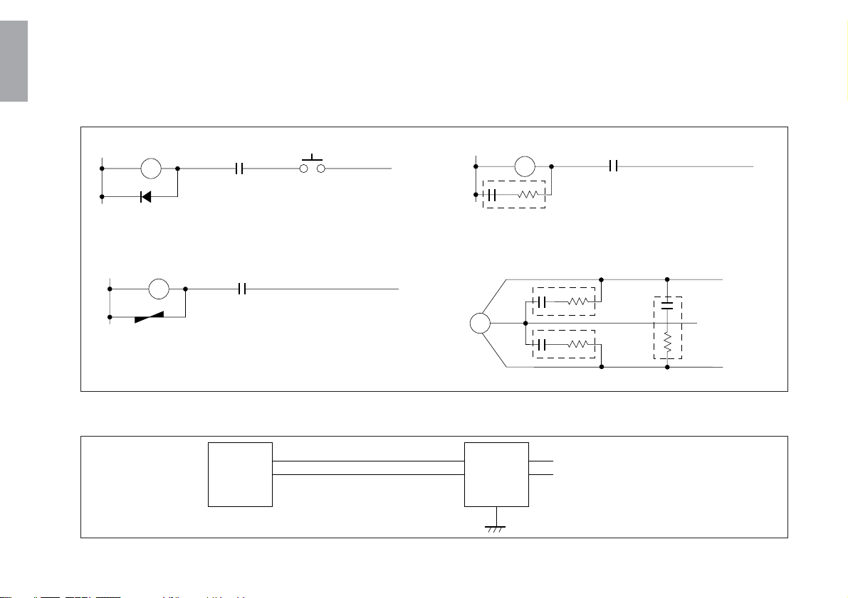
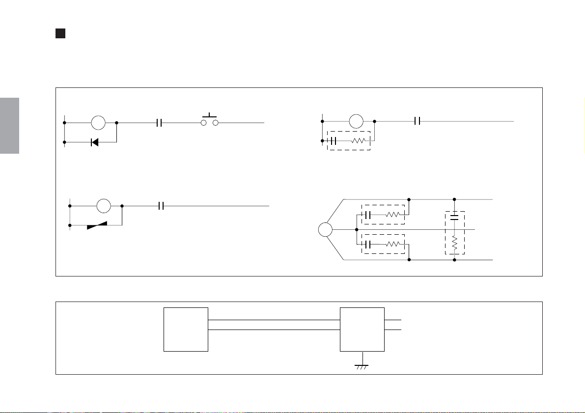
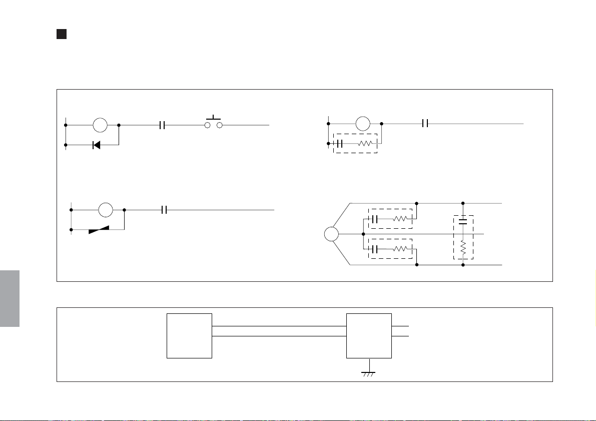
■ 雑音防止について
本機器を設置されるとき、他機器からの雑音防止のため以下の点にご注意ください。
• 本機器に結合して使用されるリレー、ソレノイド、モータなどには雑音防止の対策をしてください。
日本語
DCリレー
ダイオード
ACリレー、DCリレー
バリスタ
ACリレー、ソレノイド、モータ
スパークキラー
3相モータ
スパークキラー
• 電源ラインに他機器からの雑音が混入する恐れのある場合、その雑音防止対策をしてください。
表示ユニット
ノイズフィルタ
AC入力
IV (J)
3相
PL20C

■ 一般的な注意事項
以下は当社製品を正しくお使いいただくための一般的注意
事項です。個々の詳細な取扱上の注意は、本説明書に記述
された諸事項および注意をうながしている説明事項に従っ
てください。
• 始業または操作時には、当社製品の機能および性能が正
常に作動していることを確認してからご使用ください。
• 当社製品が万一故障した場合、各種の損害を防止するた
めの充分な保全対策を施してご使用ください。
• 仕様に示された規格以外での使用または改造を施された
製品については、機能および性能の保証はできませんの
でご留意ください。
• 当社製品を他の機器と組合わせてご使用になる場合は、
使用条件、環境などにより、その機能および性能が満足
されない場合がありますので、充分ご検討の上ご使用く
ださい。
日本語
PL20C
(J) V

日本語
VI (J)
PL20C

目次
1. 概要 ............................................................................ 1
2. 各部の名称 ................................................................. 2
3. 取付け方法 ................................................................. 3
3-1. ヘッドの取付け ......................................................... 3
3-2. ケーブルの曲げについて ......................................... 3
3-3. ヘッドケーブルユニット対スケールユニット..... 4
3-3-1. ヘッドクリアランス ...................................... 4
3-3-2. トラック・ズレ .............................................. 4
3-3-3. スケールユニットとヘッドケーブル
ユニットの相対角度 ...................................... 4
3-4. 取付け寸法図 ............................................................. 5
3-5. 表示ユニットへの接続 ............................................. 6
4. スケールユニット(SL130) ......................................... 7
4-1.各部の名称 ................................................................. 7
4-2.スケールユニット標準長 ......................................... 7
4-3. スケールユニットの取付け方法............................. 8
4-4. スケールユニットの点検と手入れ......................... 8
5. 主な仕様 ..................................................................... 9
PL20C
日本語
(J) i

日本語
ii (J)
PL20C

1. 概要
この製品は、別売のスケールユニットSL110、SL130と表示
ユニットLH71シリーズとを組み合わせることにより、位置
検出、変位量検出システムを構成することができる、デジ
ルーラ
ヘッドケーブルユニットです。
®
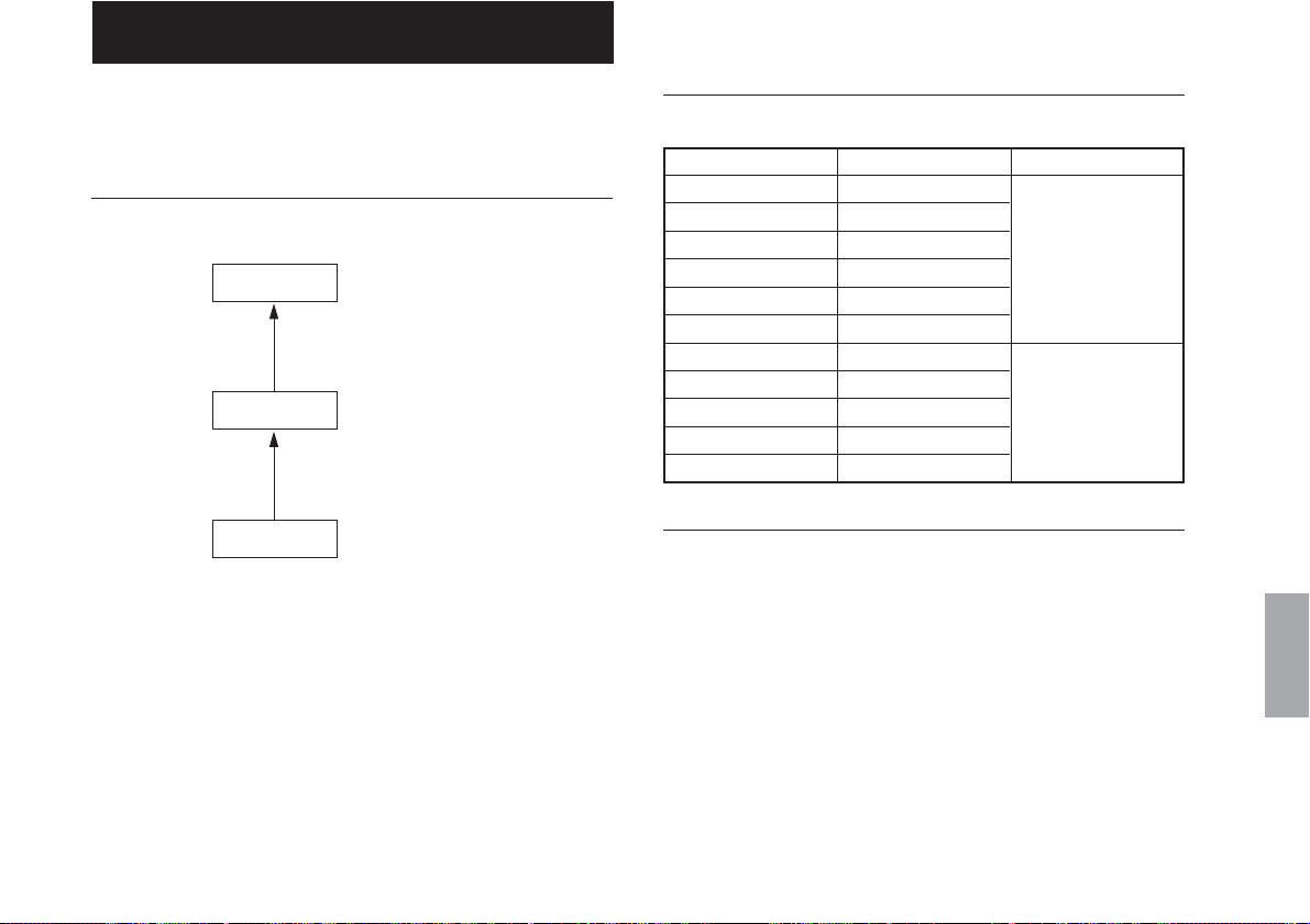
システム構成
LH71シリーズ
PL20C
SL110/SL130
表示ユニット
ヘッドケーブルユニット
スケールユニット
機種構成
型名 ケーブル長 コンジット
PL20C-3 3m
PL20C-5 5m
PL20C-10 10m
PL20C-15 15m
PL20C-20 20m
PL20C-30 30m
PL20C-3C 3m
PL20C-5C 5m
PL20C-10C 10m 有り
PL20C-15C 15m
PL20C-20C 20m
無し
主な特長
• ヘッドケーブルユニットとスケールユニットは非接触と
なっており、振動、衝撃、耐環境性に優れています。
• ヘッドケーブルユニットとスケールユニットとのクリア
ランスが大きく、取付けが容易です。
• 最小分解能は10µ mです。
日本語
PL20C
(J) 1
日本語
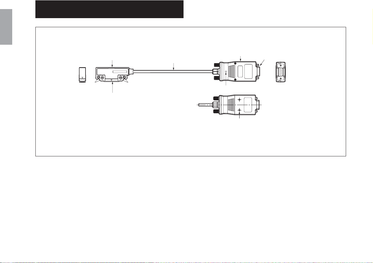
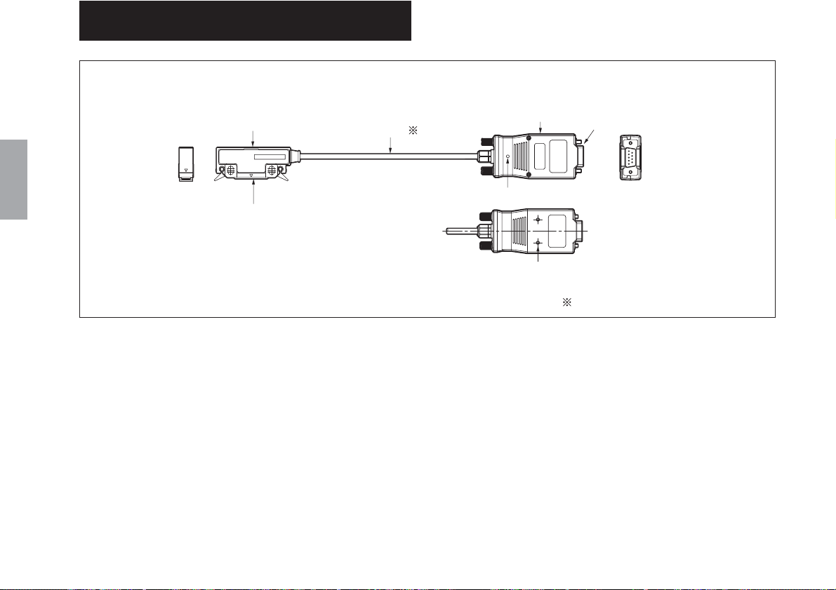
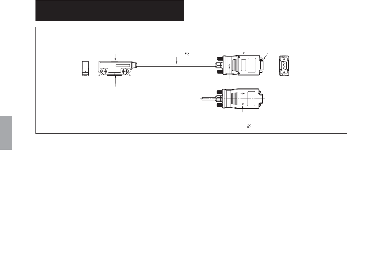
2. 各部の名称
1ヘッド部
2検出面
3ケーブル部(※)
4インターフェース
ユニット
6ステータスランプ
7インターフェースユニット
固定用タップ
※PL20C-**Cはコンジット付き
5接続コネクタ
1 ヘッド部
スケール記録信号を検出する回路が組み込まれていま
す。
2 検出面
スケールユニットの記録信号を読取ります。
3 ケーブル部
4 インターフェースユニット
表示ユニットの背面に接続します。
最適に電気調整された回路が組み込まれています。
2 (J)
5 接続コネクタ
電源としてDC+5[V]を供給することにより、スケール
信号が出力されます。
6 ステータスランプ
信号確認用のランプです。
緑色点灯:正常
赤色点灯:エラー (速度超過、ケーブル断線、信号不良)
7 インターフェースユニット固定用タップ
インターフェースユニットを固定する場合、付属の固
定板とねじを用いて固定できます。(M3深さ3mm)
PL20C

3. 取付け方法
3-1. ヘッドの取付け
ヘッド部の「▽」印がついている位置に、信号検出用セン
サが内蔵されています。
「▽」印がスケールユニットの有効長内に常にあるように
設置してください。
「▽」印
スペ−サ
• ヘッド部の固定には、ヘッド部の検出面とスケール面と
の間に付属のスペーサを挟み、付属の取付けねじ(M4×
20)を用いて取付けてください。
• 締め付けトルクは、0.7N・m〜1.1N・mとしてください。
• ヘッド部固定後、スペーサを抜き取ってください。
• スペーサ抜き取り後、ヘッド部を機械のストローク全長
に渡って動かし、ヘッド部の検出面とスケールユニット
が接触していないことを確認してください。
• ヘッド部取付け後、付属のケーブルクランプでケーブル
を固定し、ケーブル引き出し部のケーブルの遊びを押さ
えてください。
• スケールユニットとヘッドケーブルユニットの相対位置
は、"3-3.ヘッドケーブルユニット対スケールユニット"を
参照してください。
3-2. ケーブルの曲げについて
ケーブルに繰り返し曲げ応力が加わる場合には、曲げ部分
の半径が100mm以上の状態で使用してください。
日本語
PL20C
(J) 3
3-3. ヘッドケーブルユニット対
3-3-2. トラック・ズレ
日本語
スケールユニット
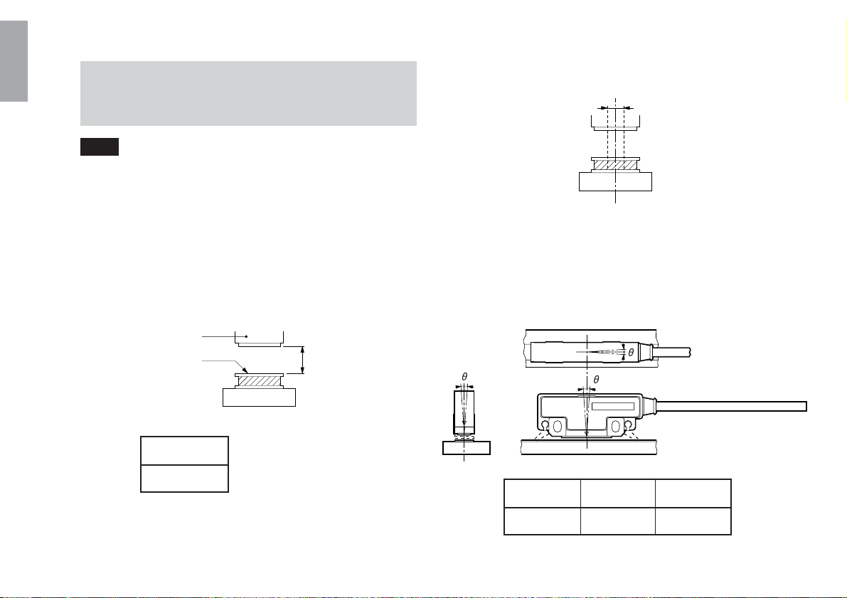
注意
ヘッドケーブルユニットとスケールユニットは機械のスト
ローク全長に渡って下記数値以内になるように設定してく
ださい。ヘッドケーブルユニット検出面とスケールユニッ
トが接触したり、下記数値以上になると、正常な動作をし
なくなります。
3-3-1. ヘッドクリアランス
ヘッド
スケールユニット
クリアランス
1.5mm以下
検出面
クリアランス
±2mm
3-3-3. スケールユニットとヘッドケーブル
ユニットの相対角度
スケ−ル面
1
3
ヘッド
θ1
2
θ2
4 (J)
±3°以下
±0.5°以下θ3±3°以下
PL20C

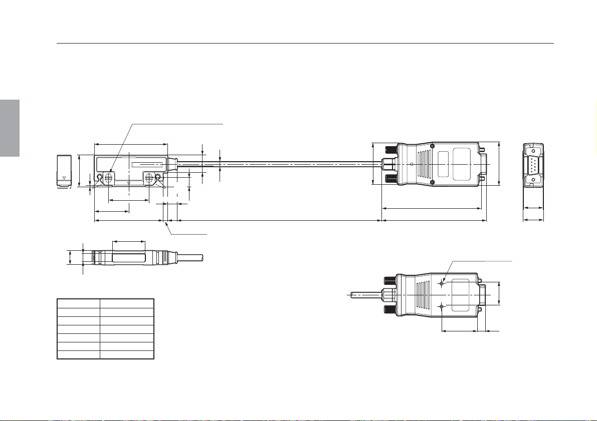
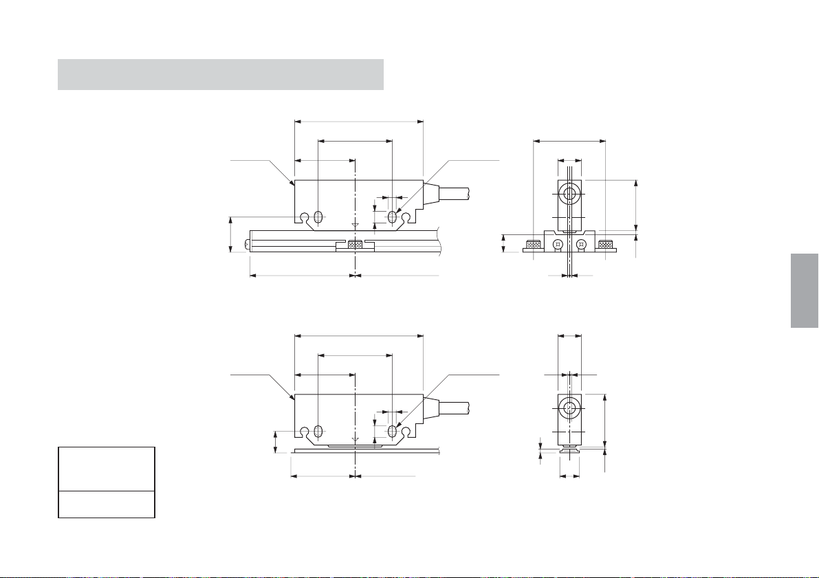
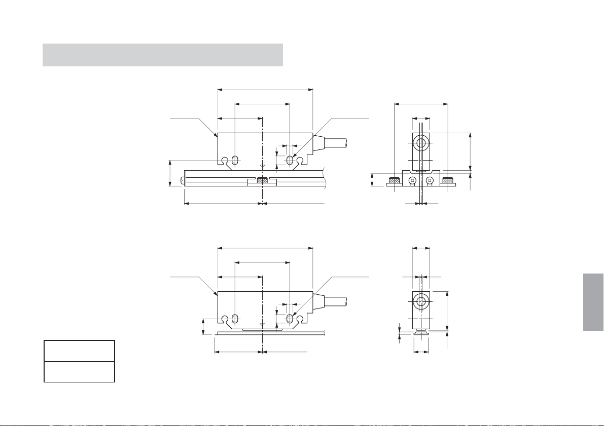
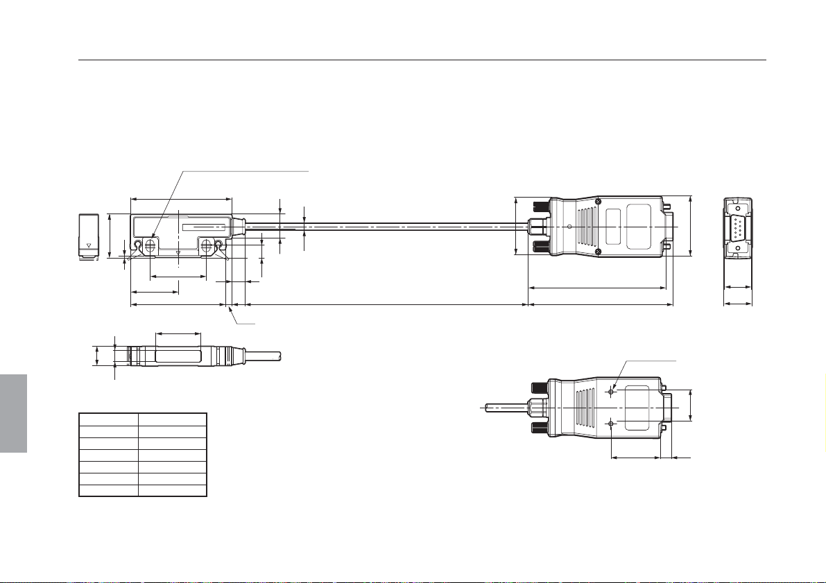
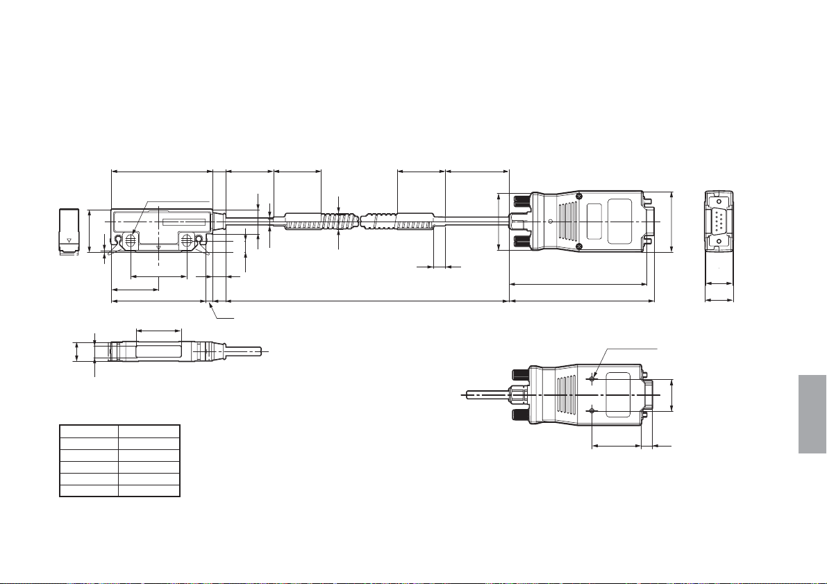
3-4. 取付け寸法図
PL20C/SL110
PL20C/SL130
ヘッド
16.8
51.5
29.5
35
63
5
7.5
有効長
M4×20用
取付け穴
単位:mm
35
12
26.5
9
–0.5
+0.5
0.8
日本語
推奨クリアランス
PL20C
0.8
ヘッド
9.1
50
29.5
35
63
5
7.5
有効長
M4×20用
取付け穴
–2
1.3
12
+2
26.5
10
クリアランス
(J) 5
日本語
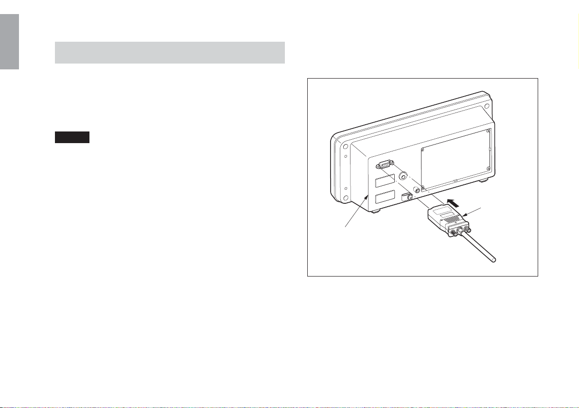
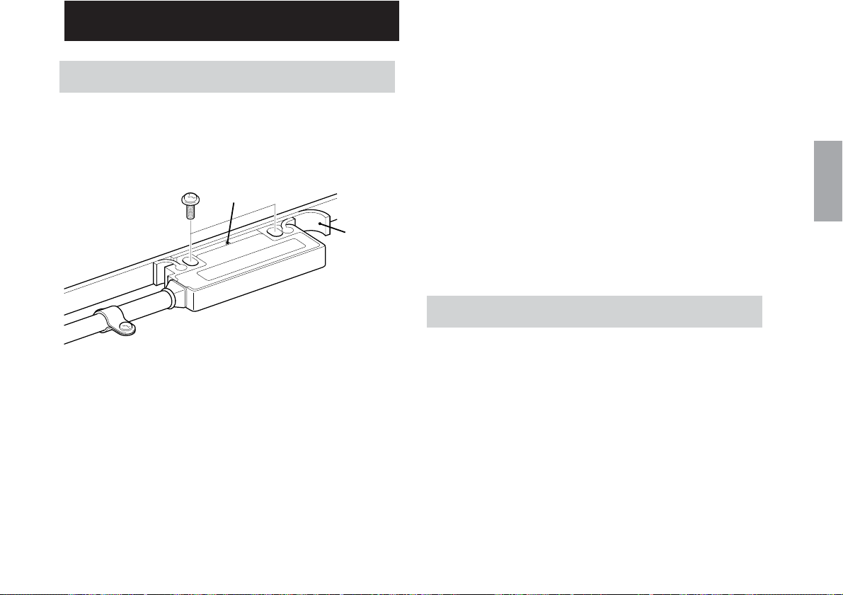
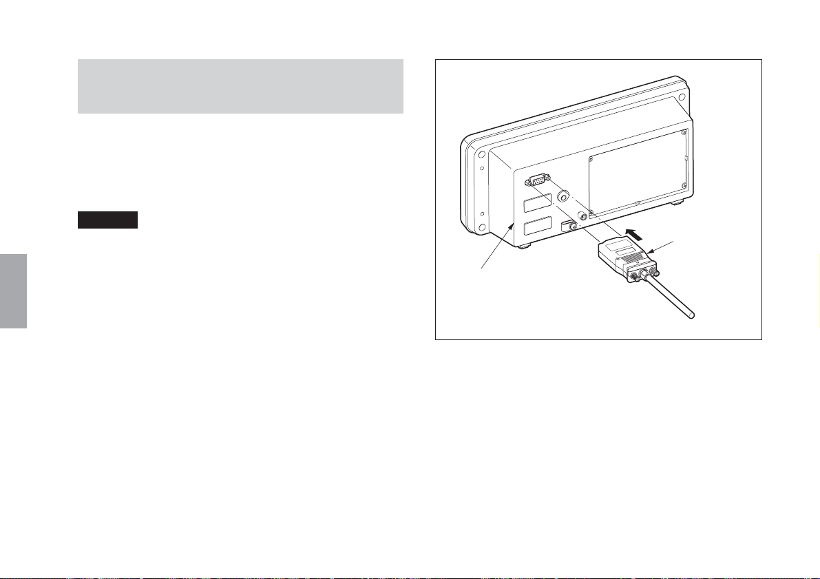
3-5. 表示ユニットへの接続
1. 表示ユニットの電源がOFFになっていることを確認し、
接続ケーブルのインターフェースユニットを表示ユ
ニット背面の1〜3のコネクタに接続します。
ご注意
スケールユニット取付け軸と表示ユニット差込みを確認し
てください。
2. インターフェースユニットのねじを用いて固定しま
す。(締付けトルク:60N·cm)
6 (J)
インターフェース
ユニット
表示ユニット背面
PL20C
4. スケールユニット(SL130)
この項は、SL130を使用する場合にお読みください。SL110
を使用する場合は、スケールユニットに付属の取扱説明書
を参照してください。
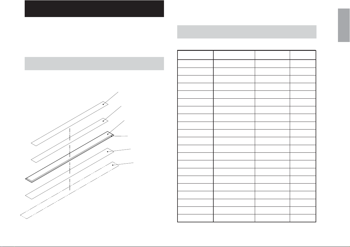
4-1.各部の名称
保護リボン:ステンレス
両面粘着テープ
スケールユニット
スケールベース
両面粘着テープ
スケールユニット
取付け面
PL20C
4-2.スケールユニット標準長
単位:mm
型名 スケール有効長 最大可動長 全長
SL130-20
SL130-30
SL130-40
SL130-50
SL130-60
SL130-70
SL130-80
SL130-100
SL130-120
SL130-150
SL130-160
SL130-170
SL130-180
SL130-200
SL130-250
SL130-300
SL130-400
SL130-500
SL130-600
SL130-700
SL130-800
200
300
400
500
600
700
800
1000
1200
1500
1600
1700
1800
2000
2500
3000
4000
5000
6000
7000
8000
230
330
430
530
630
730
830
1030
1230
1530
1630
1730
1830
2030
2530
3030
4030
5030
6030
7030
8030
300
400
500
600
700
800
900
1100
1300
1600
1700
1800
1900
2100
2600
3100
4100
5100
6100
7100
8100
日本語
(J) 7

4-3. スケールユニットの取付け方法
4-4. スケールユニットの点検と手入れ
日本語
1. 取付ける機械の近くに1時間以上放置し、機械の温度に
充分なじませてください。
2. スケールユニットを取付ける面は、極力平坦な場所を
選んでください。
取付け面の平坦度:0.4mmp-p以下
3. 清浄な布にアルコールを含ませ、スケールユニット取
付け面とスケールベース裏面の油や汚れを拭き取って
ください。その後、スケールユニット取付け面に付属
の両面粘着テープを貼付け、機械に取付けます。
4. スケールユニット取付け後、清浄な布などにアルコー
ルを含ませてスケール面(ゴム磁石) を軽く拭き、ゴ
ミ、油などを取り除きます。
5. 次に付属の両面粘着テープをスケール面に貼ります。
そして、スケール面からはみ出さないように、裏紙を
はがしながら保護リボンを注意深く貼付けます。
注意
• スケール面を保護するため、必ず付属の保護リボンを
貼ってご使用ください。
• 保護リボンは折ったり、曲げたりしないよう、取扱いに
は充分ご注意ください。
塵埃、切粉、切削油などのかかる場所でご使用になる場合
は、ときどき布などでスケール面を軽く拭いてください。
ただし、アルコール、洗剤などは使用しないでください。
8 (J)
PL20C

5. 主な仕様
ヘッドケーブルユニット(PL20C)
使用温度範囲 : 0〜45°C
保存温度範囲 : –10〜50°C
ケーブル長 : 3m(PL20C-3/-3C)
5m(PL20C-5/-5C)
10m(PL20C-10/-10C)
15m(PL20C-15/-15C)
20m(PL20C-20/-20C)
30m(PL20C-30)
出力信号 : A/B相(EIA-422準拠)
分解能 : 10µm
最大応答速度 : 300m/分
付属品 : ヘッド取付けねじ(M4×20) ..................... 2
ケ−ブルクランプ用ねじ(M4×8) ........... 3
取扱説明書 ................................................... 1
ケ−ブルクランプ....................................... 3
スぺ−サ .......................................................1
スケールユニット(SL130)(別売)
精度(20°Cにて)(*):
有効長
有効長=8000mm 50+10L/1000+20µm
温度膨張係数 : 10.4±1×10
使用温度範囲 : –5〜45°C
保存温度範囲 : –10〜50°C
付属品 : 保護リボン......................................... 1
7000mm 50+10L/1000µm
(L:有効長(mm))
* ヘッドケーブルユニットPL20Cと
の組合せによります。
–6
/°C
両面粘着テープ................................. 1
機銘板................................................. 1
シリアルナンバーラベル ................ 1
日本語
PL20C
(J) 9
日本語
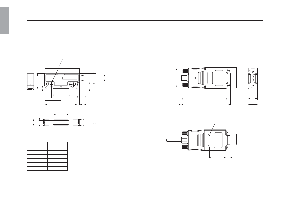
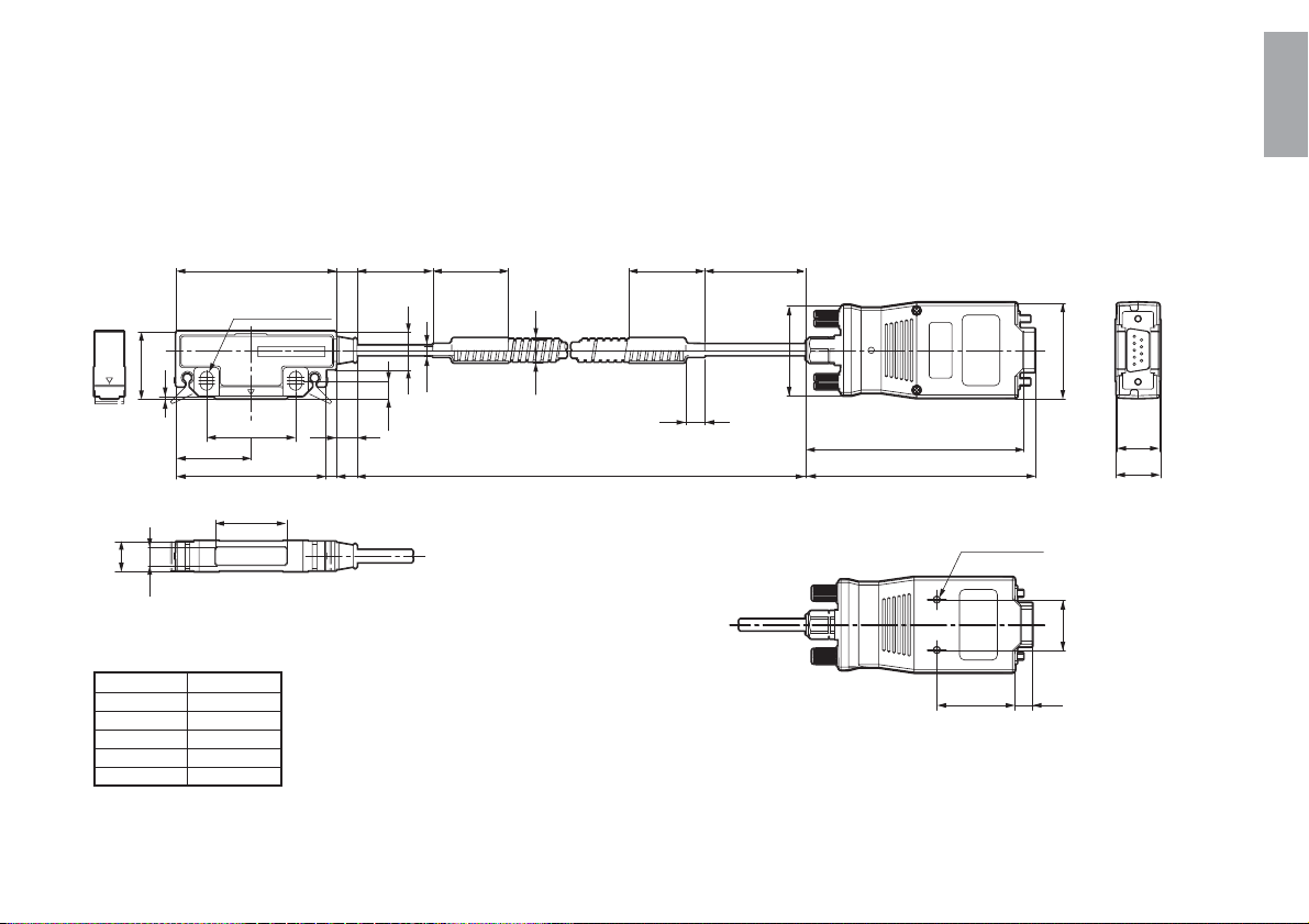
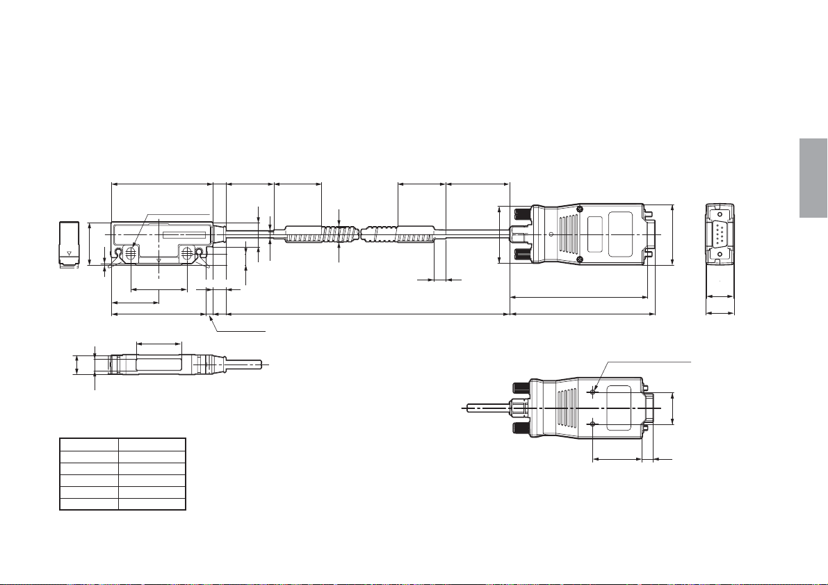
外形寸法図
PL20C-**
単位:mm
2-φ5 × 7.5取付け穴
63
26.4
1
29.5
7
12
ケーブル長
PL20C-3 3000
PL20C-5 5000
PL20C-10 10000
PL20C-15 15000
PL20C-20 20000
PL20C-30 30000
10 (J)
φ4
15
35
59
28
8.2
(4)
6.9
ケーブル長
(36)
(86.5)
(91)
2-M3深さ3
(31)
(38)
(17)
(17.7)
20
(7)
製品は一部改良のため、予告なく外観、仕様を変更するこ
とがあります。
PL20C
PL20C-**C
単位:mm
63
2-φ5 × 7.5取付け穴
+10
0
30 30 ±2 30 ±2
日本語
40 ±5
26.4
1
35
29.5
59
28
7
12
ケーブル長
PL20C-3C 3000
PL20C-5C 5000
PL20C-10C 10000
PL20C-15C 15000
PL20C-20C 20000
PL20C
8.2
(4)
6.9
(38)
φ4
15
φ9
7.5
ケーブル長
(36)
(86.5)
(91)
2-M3深さ3
(31)
(17)
(17.7)
20
(7)
製品は一部改良のため、予告なく外観、仕様を変更するこ
とがあります。
(J) 11

日本語
12 (J)
PL20C
Safety Precautions
Magnescale Co., Ltd. products are designed in full consideration of safety. However, improper
handling during operation or installation is dangerous and may lead to fire, electric shock or other
accidents resulting in serious injury or death. In addition, these actions may also worsen machine
performance.
Therefore, be sure to observe the following safety precautions in order to prevent these types of
accidents, and to read these “Safety Precautions” before operating, installing, maintaining,
inspecting, repairing or otherwise working on this unit.
Warning indication meanings
The following indications are used throughout this manual, and their
contents should be understood before reading the text.
Warning
Failure to observe these precautions may lead to fire, electric shock
or other accidents resulting in serious injury or death.
Caution
Failure to observe these precautions may lead to electric shock or
other accidents resulting in injury or damage to surrounding objects.
Note
This indicates precautions which should be observed to ensure
proper handling of the equipment.
PL20C
Symbols requiring attention
English
CAUTION ELECTRICAL
SHOCK
Symbols prohibiting actions
DO NOT
DISASSEMBLE
Symbols specifying actions
UNPLUGGING
(E) I
English
Warning
• Do not use this unit with voltages other than the specified supply voltage as this may
result in fire or electric shock.
• Do not perform installation work with wet hands as this may result in electric shock.
• Do not disassemble or modify the unit as this may result in injury or damage the
internal circuits.
Caution
• Be sure to check the machine and device conditions to ensure work safety before
working on the machine.
• Be sure to cut off the power supply, air and other sources of drive power before
working on the machine. Failure to do so may result in fire or accidents.
II (E)
• When turning on the power supply, etc. to operate the machine, take care not to catch
your fingers in peripheral machines and devices.
PL20C

Operating and Installation Precautions
Operating cautions
• Do not open the cover of this device or put your hand inside.
Otherwise the internal circuit may be broken by static
electricity.
• This device is not explosion-proof. Do not use it in the
atmosphere of flammable gas.
• This device is not vibration resistant. Do not use it in a place
where it is subject to shocks. (Excluding the head assembly)
• Do not allow two scales to contact or overlap each other.
When installing, keep a read head and a scale unit as far as
possible from a strong magnetic force. (It is adequate if the
magnetic force does not exceed about 30 × 10
• When using this system, it is recommended that the scale unit
be installed on the movable side and the head installed on the
stationary side.
• The interface unit is pre-adjusted, and so never disassemble it.
Accuracy can no longer be guaranteed if they are
disassembled.
-4
T.)
Installation
• Use the PL20C in the temperature range of 0 to 45 °C / 32 to
113 °F. Do not expose it to the sunlight or source of heat. A
well-ventilated place is preferable.
• Install the PL20C at least 0.5 m away from noise sources such
as large-power relays, high-voltage sources, large-current
switch, Inverter high electric power.
• Separately route the head cable unit from the power line.
• When the system is exposed to cutting chips, oil and coolant,
provide a cover. Some coolants may affect the functions of
product. Please provide necessary protections.
English
PL20C
(E) III
Noise Prevention
When installing the scale unit, observe the following to prevent noise interference from other equipment.
• Apply preventive measures to relays, solenoids and motors connected to the scale unit against noise interference.
English
DC relay
Diode
AC relay, DC relay
Varistor
AC relay, solenoid, motor
Spark killer
3-phase motor
3-phase
Spark killer
• Take preventive steps when the noises from other equipment may disturb the power supply line to the scale unit.
Counter unit
Noise filter
AC input
IV (E)
PL20C

General precautions
When using Magnescale Co., Ltd. products, observe the
following general precautions along with those given
specifically in this manual to ensure proper use of the
products.
• Before and during operations, be sure to check that our
products function properly.
• Provide adequate safety measures to prevent damages
in case our products should develop malfunctions.
• Use outside indicated specifications or purposes and
modification of our products will void any warranty of the
functions and performance as specified of our products.
• When using our products in combination with other
equipment, the functions and performances as noted in
this manual may not be attained, depending on operating
and environmental conditions.
English
PL20C
(E) V

English
VI (E)
PL20C

Contents
1. Overview ..................................................................... 1
2. Name of each part ...................................................... 2
3. Installation .................................................................. 3
3-1. Head installation .......................................................... 3
3-2. Cable bending .............................................................. 3
3-3. Head cable unit and scale unit ................................... 4
3-3-1. Head clearance ..................................................... 4
3-3-2. Track deviation ..................................................... 4
3-3-3. Scale unit and head cable unit .............................. 4
3-4. Mounting Dimensions ................................................. 5
3-5. Connecting the interface unit to a counter unit ........... 6
4. Scale unit (SL130) ......................................................7
4-1. Name of each part ........................................................ 7
4-2. Standard scale units ..................................................... 7
4-3. Scale unit installation ................................................... 8
4-4. Maintenance of scale unit ............................................ 8
English
5. Specifications ............................................................. 9
PL20C
(E) i

English
ii (E)
PL20C

1. Overview
This product is a DIGIRULER
head cable unit that enables
®
configuration of a position detection and displacement detection
system by combining the SL110 or SL130 scale and LH71 series
counter (all sold separately).
System Configuration
LH71 series
PL20C
SL110/SL130
Counter unit
Head cable unit
Scale unit
Model Configuration
Model name Cable length Conduit
PL20C-3 3 m
PL20C-5 5 m
PL20C-10 10 m
PL20C-15 15 m
PL20C-20 20 m
PL20C-30 30 m
PL20C-3C 3 m
PL20C-5C 5 m
PL20C-10C 10 m Included
PL20C-15C 15 m
PL20C-20C 20 m
Not included
Main Features
• The head cable unit and scale unit are based on a non-contact
system for providing superior resistance to vibrations, shocks,
and workshop conditions.
• The head cable unit and scale unit have a large clearance for
easy installation.
• Minimum resolution: 10 µm
English
PL20C
(E) 1
2. Name of each part
English
1 Read head
2 Detection surface
1 Read head
The read head incorporates circuits that detect scale
recording signals.
2 Detection surface
This surface reads the recording signals of the scale unit.
3 Cable
4 Interface unit
This is connected to the rear panel of the counter unit.
The interface unit incorporates circuits that have been
electrically adjusted to the optimal setting.
3 Cable ( )
4 Interface unit
5 Connector
6 Status lamp
7 Interface unit tap for fixing
The PL20C-**C includes a conduit.
5 Connector
Scale signals are output when DC +5 V is supplied as the
power source.
6 Status lamp
This is a lamp for checking the signals.
Lit green : Normal
Lit red : Error (Overspeed, cable disconnection, invalid
signal)
7 Interface unit tap for fixing
The interface unit can be secured in place using the supplied
fixing plate and screw. (M3 depth 3 mm)
2 (E)
PL20C
3. Installation
3-1. Head installation
The detection signal sensor is built into read head where it is
marked with "∇". Install the read head so that the "∇" mark is
always within the measuring length of the scale unit.
"∇" mark
Spacer
• To fasten the head, insert the accessory spacer between the
detection surface of the head and the scale, and install with the
accessory screws (M4 × 20).
• Tightening torque should be 0.7 N·m to 1.1 N·m.
•After fixing the head, remove the spacer.
• After removing the spacer, move the scale throughout the
machine's travel and check that the detecting surface of the
head and the scale are not in contact.
•After installing the head, use the accessory cable clamps to
securely fasten the cable where it extends from the head.
• The relative positions of the scale unit and head cable unit
should be as shown in "3-3. Head cable unit and scale unit" .
3-2. Cable bending
If the cable is bent repeatedly, the radius of the curves should not
less than 100 mm/3.9".
English
PL20C
(E) 3

3-3. Head cable unit and scale unit
3-3-2. Track deviation
English
Note
Make sure that the head cable unit and scale unit clearance
remains within the value given below.
If the head cable unit and scale unit touch one another or the
clearance is smaller than specified, the system will not operate
normally.
3-3-1. Head clearance
Read head
Scale unit
Clearance
1.5 mm/0.06"
Detection surface
or less
Clearance
±2 mm
/±0.08"
3-3-3. Scale unit and head cable unit
Scale surface
1
3
Read head
θ
1
±3° or less
2
θ
2
±0.5° or less
θ
3
±3° or less
4 (E)
PL20C

3-4. Mounting Dimensions
PL20C / SL110
PL20C / SL130
Recommended
Clearance
0.8 / 0.03"
PL20C
Read head
16.8/0.66"
Read head
51.5/2.03"
9.1/0.36"
29.5/1.16"
29.5/1.16"
50/1.97"
63/2.48"
35/1.38"
5/0.2"
7.5/0.3"
Measuring length
63/2.48"
35/1.38"
5/0.2"
7.5/0.3"
Measuring length
Mounting
hole for M4 ×
20 screw
9/0.35"
–0.5/–0.02"
Mounting
hole for M4 ×
20 screw
–2/–0.08"
1.3/0.05"
Umit : mm/inch
35/1.38"
12/0.47"
26.5/1.04"
English
+0.5/+0.02"
0.8/0.03"
12/0.47"
+2/+0.08"
26.5/1.04"
10/0.39"
Clearance
(E) 5

English
3-5. Connecting the interface unit to
a counter unit
1. Check that the counter unit power is off. Then, connect the
interface unit of the connection cable with the connector 1-3
on the rear panel of counter unit.
Note
Check the scale unit mounting axis and counter unit insertion.
2. Secure the interface unit using the screws. (Tightening
torque: 60 N·cm)
Interface unit
Rear panel of counter unit
6 (E)
PL20C

4. Scale unit (SL130)
The description below applies when using SL130. When SL110
is connected, see the instruction manual supplied with it.
4-1. Name of each part
Protective ribbon : Stainless steel
Double-sided
adhesive tape
Scale unit
Scale base
(part of the scale unit)
Double-sided
adhesive tape
Scale unit
mounting surface
4-2. Standard scale units
Model
SL130-20
SL130-30
SL130-40
SL130-50
SL130-60
SL130-70
SL130-80
SL130-100
SL130-120
SL130-150
SL130-160
SL130-170
SL130-180
SL130-200
SL130-250
SL130-300
SL130-400
SL130-500
SL130-600
SL130-700
SL130-800
Measuring length
200/ 7.9"
300/ 11.8"
400/ 15.7"
500/ 19.7"
600/ 23.6"
700/ 27.6"
800/ 31.5"
1000/ 39.4"
1200/ 47.2"
1500/ 59.1"
1600/ 63.0"
1700/ 66.9"
1800/ 70.9"
2000/ 78.7"
2500/ 98.4"
3000/118.1"
4000/157.5"
5000/196.9"
6000/236.2"
7000/275.6"
8000/315.0"
Max. travel
230/ 9.1"
330/ 13.0"
430/ 16.9"
530/ 20.9"
630/ 24.8"
730/ 28.7"
830/ 32.7"
1030/ 40.6"
1230/ 48.4"
1530/ 60.2"
1630/ 64.2"
1730/ 68.1"
1830/ 72.0"
2030/ 79.9"
2530/ 99.6"
3030/119.3"
4030/158.7"
5030/198.0"
6030/237.4"
7030/276.8"
8030/316.1"
Unit: mm/inch
Overall length
300/ 11.8"
400/ 15.7"
500/ 19.7"
600/ 23.6"
700/ 27.6"
800/ 31.5"
900/ 35.4"
1100/ 43.3"
1300/ 51.2"
1600/ 63.0"
1700/ 66.9"
1800/ 70.9"
1900/ 74.8"
2100/ 82.7"
2600/ 102.4"
3100/ 122.0"
4100/ 161.4"
5100/ 200.8"
6100/ 240.2"
7100/ 279.5"
8100/ 318.9"
English
PL20C
(E) 7

4-3. Scale unit installation
4-4. Maintenance of scale unit
English
1. Leave the scale near installation unit for about an hour so all
components will be at the same temperature when the
installtion is performed.
2. Mount the scale unit on a surface with a flatness of 0.4/
0.016" mm or less.
3. Wipe the scale unit mounting surface and scale base
mounting surface with a clean, alcohol-moistened cloth to
remove, dirt, oil, etc. Attach the supplied double-sided
adhesive tape to the scale unit mounting surface and then
stick the scale to the machine.
4. Wipe the scale surface (rubber magnet) softly with clean,
alcohol-moistened cloth to remove dirt, oil, etc.
5. Attach the supplied double-sided adhesive tape to the scale
surface. Stick the protective ribbon to the scale from one end
while removing the lining paper.
Make sure the ribbon does not stick out from the scale edges.
Note
• Apply the protective ribbon (provided) over the scale for
protection purpose.
•When handling the protective ribbon, use care not to bend it.
When scale unit is exposed to dust, chips and coolant, wipe the
scale surface softly with cloth occasionally.
Do not use alcohol and detergent.
8 (E)
PL20C

5. Specifications
Head cable unit (PL20C)
Temperature
Operating :0 to 45 °C / 32 to 113 °F
Storage : –10 to 50 °C / 14 °F to 122 °F
Cable length :3 m (PL20C-3/-3C)
5 m (PL20C-5/-5C)
10 m (PL20C-10/-10C)
15 m (PL20C-15/-15C)
20 m (PL20C-20/-20C)
30 m (PL20C-30)
Output signal :A/B quadrature signal
(compliant with EIA-422)
Resolution : 10 µm
Maximum response speed
: 300 m/min.
Accessories : Read head installation screws
(M4 × 20) ....................................... 2
Cable clamp screws (M4 × 8) ....... 3
Instruction manual .........................1
Cable clamps ................................. 3
Spacer ........................................... 1
Scale unit (SL130) (sold separately)
Accuracy (at 20 °C)*:
Measuring length
Measuring length = 8000 µm
Thermal extension coefficient:
Temperature
Operating : –5 to 45 °C/23 to 113 °F
Storage : –10 to 50 °C/14 to 122 °F
Accessories :Protective ribbon ........................... 1
7000 mm
50 + 10L/1000 µm
50 + 10L/1000 + 20 µm
(L: Measuring length (mm))
* When combined with the PL20C
head cable unit.
10.4 ±1 × 10
–6
/°C
Double-side adhesive tape............ 1
Name plate .................................... 1
Serial number label ....................... 1
English
PL20C
(E) 9
Dimensions
PL20C-**
unit: mm/inch
2-φ5 × 7.5 mounting hole
2-φ0.2" × 0.3" mounting hole
63/2.48"
English
1/0.04"
26.4/1.04"
35/1.38"
29.5/1.17"
59/2.32"
7/0.28"
12/0.47"
Cable length
PL20C-3 3000/118.1"
PL20C-5 5000/196.9"
PL20C-10 10000/393.7"
PL20C-15 15000/590.6"
PL20C-20 20000/787.4"
PL20C-30 30000/1181.1"
28/1.10"
10 (E)
8.2/0.32"
(4)/(0.16")
6.9/
0.27"
15/0.59"
φ4/0.16"
Cable length
(38)/(1.5")
20/0.8"
(17)/
(0.67")
(17.7)/
(0.67")
(36)/(1.42")
(86.5)/(3.41")
(91)/(3.58")
(31)/(1.22")
2-M3 depth 3/0.12"
(7)/(0.28")
Specifications and appearances of the products are subject to
change for improvement without prior notice.
PL20C
PL20C-**C
unit: mm/inch
63/2.48"
2-φ5 × 7.5 mounting hole
×
0.3" mounting hole
2-φ0.2"
1/0.04"
26.4/1.04"
35/1.38"
29.5/1.17"
59/2.32"
7/0.28"
12/0.47"
Cable length
PL20C-3C 3000/118.1"
PL20C-5C 5000/196.9"
PL20C-10C 10000/393.7"
PL20C-15C 15000/590.6"
PL20C-20C 20000/787.4"
PL20C
28/1.10"
30 /1.18 "
8.2/0.32"
(4)/(0.16")
+ 10 0+ 0.4
6.9/
0.27"
15/0.59"
30 ±2/
0
1.18" ±0.08"
φ4/φ0.16"
φ9/φ0.35"
Cable length
30 ±2/
1.18" ±0.08"
40 ±5/
1.57" ±0.2"
7.5/0.3"
(36)/(1.4")
(38)/(1.5")
(86.5)/(3.41")
(91)/(3.58")
2-M3 depth 3/0.12"
20/0.8"
(31)/(1.22") (7)/(0.28")
Specifications and appearances of the products are subject to
change for improvement without prior notice.
(17)/
(0.67")
(17.7)/
(0.67")
(E) 11
English

English
12 (E)
PL20C
Sicherheitsmaßnahmen
Bei dem Entwurf von Magnescale Co., Ltd. Produkten wird größter Wert auf die Sicherheit gelegt. Unsachgemäße
Handhabung während des Betriebs oder der Installation ist jedoch gefährlich und kann zu Feuer, elektrischen
Schlägen oder anderen Unfällen führen, die schwere Verletzungen oder Tod zur Folge haben können. Darüber
hinaus kann falsche Behandlung die Leistung der Maschine verschlechtern.
Beachten Sie daher unbedingt die besonders hervorgehobenen Vorsichtshinweise in dieser Bedienungsanleitung,
um derartige Unfälle zu verhüten, und lesen Sie die folgenden Sicherheitsmaßnahmen vor der Inbetriebnahme,
Installation, Wartung, Inspektion oder Reparatur dieses Gerätes oder der Durchführung anderer Arbeiten durch.
Bedeutung der Warnhinweise
Bei der Durchsicht dieses Handbuchs werden Sie auf die folgenden
Hinweise und Symbole stoßen. Machen Sie sich mit ihrer
Bedeutung vertraut, bevor Sie den Text lesen.
Warnung
Eine Missachtung dieser Hinweise kann zu Feuer, elektrischen
Schlägen oder anderen Unfällen führen, die schwere Verletzungen
oder Tod zur Folge haben können.
Vorsicht
Eine Missachtung dieser Hinweise kann zu elektrischen Schlägen
oder anderen Unfällen führen, die Verletzungen oder
Sachbeschädigung der umliegenden Objekte zur Folge haben
können.
Hinweis
Diese Hinweise sollten beachtet werden, um eine korrekte
Handhabung des Gerätes zu gewährleisten.
PL20C
Zu beachtende Symbole
VORSICHT
ELEKTRISCHER
SCHLAG
Symbole, die Handlungen verbieten
NICHT
ZERLEGEN
Symbole, die Handlungen vorschreiben
STECKER ABZIEHEN
(G) I
Deutsch

Warnung
• Betreiben Sie dieses Gerät nur mit der vorgeschriebenen Versorgungsspannung, da
• Führen Sie Installationsarbeiten nicht mit nassen Händen aus, da hierbei die Gefahr
• Unterlassen Sie jeden Versuch, das Gerät zu zerlegen oder umzubauen, da dies zu
Vorsicht
anderenfalls die Gefahr von Feuer oder elektrischen Schlägen besteht.
elektrischer Schläge besonders groß ist.
Verletzungen oder Beschädigung der internen Schaltungen führen kann.
Deutsch
II (G)
• Überprüfen Sie vor Arbeitsbeginn unbedingt den Zustand von Maschine und
Vorrichtungen, um die Arbeitssicherheit zu gewährleisten.
• Schalten Sie unbedingt die Strom- und Luftversorgung sowie andere
Antriebskraftquellen aus, bevor Sie Arbeiten an der Maschine ausführen.
Anderenfalls kann es zu Feuer oder Unfällen kommen.
• Achten Sie beim Einschalten der Stromversorgung usw. zum Betrieb der Maschine
darauf, dass Sie sich nicht die Finger in peripheren Maschinen und Vorrichtungen
klemmen.
PL20C

Vorsichtsmaßnahmen zu Betrieb und Installation
Allgemeine Betriebshinweise
• Bei Öffnung der Abdeckung des Geräts oder Einführung der
Hand darin kann der innere Stromkreis durch statische
Elektrizität beschädigt werden.
• Das Gerät ist nicht explosionsgeschützt, daher kann es nicht in
entzündbarem Gas verwendet werden.
• Das Gerät ist nicht schüttelfest, daher kann es nicht an so
einem Ort verwendet werden, an dem es Erschütterung
ausgesetzt ist. (Ausschließlich des Lesekopfaufbaus)
• Achten Sie darauf, dass zwei Maßstäbe sich nicht berühren
oder überlappen. Bei der Installation halten Sie den Lesekopf
und die Maßstabseinheit möglichst weit von einer starken
Magnetkraft entfernt. (Der Abstand ist ausreichend, wenn die
Magnetkraft einen Wert von etwa 30 × 10
überschreitet.)
• Bei Verwendung dieses Systems wird empfohlen, die
Maßstabseinheit auf der beweglichen Seite und den Kopf auf
der feststehenden Seite zu installieren.
• Da die Schnittstelleneinheit voreingestellt ist, darf sie
keinesfalls zerlegt werden. Falls sie zerlegt wird, kann die
Genauigkeit nicht mehr garantiert werden.
-4
T nicht
Installation
• Betreiben Sie den PL20C an einem gut ventilierten Platz, der eine
Temperatur zwischen 0 °C bis +45 °C aufweist und keinem
prallen Sonnenlicht oder Wärmequellen ausgesetzt ist.
• Installieren Sie den PL20C mindestens 0,5 m von Störquellen wie
Relais und Schalter hoher Leistung, Inverter hoher Leistung,
Hochspannungsquellen usw. entfernt.
• Verlegen Sie die Kopfkabeleinheit vom Stromversorgungskabel
getrennt.
• Versehen Sie das Gerät mit einer Abdeckung, wenn das Gerät
direkt Schneidspänen, Schneidöl oder Kühlmittel ausgesetzt ist.
Einige Kühlmittel können die Funktion des Gerätes
beeinträchtigen. Geeignete Vorsichtsmaßnahmen sind
vorzusehen.
Deutsch
PL20C
(G) III

Lärmschutz
Um Störungen durch andere Anlagen zu vermeiden, ist bei der Installation der Maßstabseinheit auf Folgendes zu achten.
• Treffen Sie alle notwendigen Maßnahmen, um Störungen durch Relaisscahlter, Elektromagneten und Motor zu vermeiden.
Deutsch
Gleichstromrelais
Diode
Wechselstromrelais, Gleichstromrelais
Varistor
Wechselstromrelais, Elektromagnetschalter, Motor
Funkschutz
3-Phasenmotor
3-Phasen
Funkschutz
• Um Störungen der Maßstabseinheit-Stromzufuhr zu verhindern, sollten auch hier vorbeugende Maßnahmen getroffen werden.
Anzeigeeinheit
Störfilter
Wechselstromversorgung
IV (G)
PL20C

Allgemeine Vorsichtsmaßnahmen
Beachten Sie bei der Verwendung von Magnescale Co.,
Ltd. Produkten die folgenden allgemeinen sowie die in
dieser Anleitung besonders hervorgehobenen
Vorsichtsmaßnahmen, um eine sachgerechte Behandlung
der Produkte zu gewährleisten.
• Vergewissern Sie sich vor und während des Betriebs,
dass unsere Produkte einwandfrei funktionieren.
• Sorgen Sie für geeignete Sicherheitsmaßnahmen, um im
Falle von Gerätestörungen Schäden auszuschließen.
• Wenn das Profukt modifiziert oder nicht seinem Zweck
entsprechend verwendet wird, erlischt die Garantie für
die angegebenen Funktionen und Leistungsmerkmale.
• Bei Verwendung unserer Produkte zusammen mit
Geräten anderer Hersteller werden je nach den
Umgebungsbedingungen die in der Anleitung
beschriebenen Funktionen und Leistungsmerkmale
möglicherweise nicht erreicht.
Deutsch
PL20C
(G) V

Deutsch
VI (G)
PL20C

Inhaltsverzeichins
1. Überblick ..................................................................... 1
2. Teilebezeichnungen................................................... 2
3. Installation .................................................................. 3
3-1. Lesekopf-Installation ................................................... 3
3-2. Kabelbiegeradius ......................................................... 3
3-3. Kopfkabeleinheit und Maßstabseinheit ....................... 4
3-3-1. Kopftoleranz ......................................................... 4
3-3-2. Spurabweichung ................................................... 4
3-3-3. Maßstabseinheit und Kopfkabeleinheit ............... 4
3-4. Konstruktionszeichnung .............................................. 5
3-5. Anschließen der Schnittstelleneinheit an eine
Zählereinheit ................................................................ 6
4. Maßstabseinheit (SL130)........................................... 7
4-1. Teilebezeichnungen ..................................................... 7
4-2. Standardmaßstäbe ........................................................ 7
4-3. Maßstabseinheitaufstellung ......................................... 8
4-4. Wartung der Maßstabseinheit ...................................... 8
Deutsch
5. Technische Daten ...................................................... 9
PL20C
(G) i

Deutsch
ii (G)
PL20C

1. Überblick
Dieses Gerät ist eine DIGIRULER® Kopfkabeleinheit, welche die
Konfiguration eines Positions- und Verschiebungserkennungssystems
durch Kombinieren mit einem Maßstab SL110 oder SL130 mit einem
Zähler der Serie LH71 (alle getrennt erhältlich) ermöglicht.
Systemkonfiguration
Serie LH71
PL20C
Anzeigeeinheit
Kopfkabeleinheit
Modellkonfiguration
Modellbezeichnung Kabellänge Isolierrohr
PL20C-3 3 m
PL20C-5 5 m
PL20C-10 10 m
PL20C-15 15 m
PL20C-20 20 m
PL20C-30 30 m
PL20C-3C 3 m
PL20C-5C 5 m
PL20C-10C 10 m Mitgeliefert
PL20C-15C 15 m
PL20C-20C 20 m
Nicht mitgeliefert
Hauptmerkmale
PL20C
SL110/SL130
Maßstabseinheit
• Kopfkabeleinheit und Maßstabseinheit basieren auf einem
kontaktlosen System, um überragende Beständigkeit gegen
Vibrationen, Stöße und widrige Umweltbedingungen zu
bieten.
• Der große Abstand zwischen Kopfkabeleinheit und
Maßstabseinheit erleichtert die Installation.
• Minimale Auflösung: 10 µm
(G) 1
Deutsch
2. Teilebezeichnungen
Deutsch
1 Lesekopf
2 Lesefläche
1 Lesekopf
Der Lesekopf enthält Schaltungen, welche die
Maßstabsaufzeichnungssignale erkennen.
2 Lesefläche
Diese Fläche liest die Aufzeichnungssignale der
Maßstabseinheit.
3 Kabel
4 Schnittstelleneinheit
Die Schnittstelleneinheit wird an die Schnittstelle an der
Rückwand der Anzeigeeinheit angeschlossen.
Die Schnittstelleneinheit verfügt über eine Schaltung, die
optimal elektrisch eingestellt wurde.
3 Kabel ( )
4 Schnittstelleneinheit
5 Steckverbinder
6 Statuslampe
7 Schnittstelleneinheit-Befestigungsgewinde
PL20C-**C schließt ein Isolierrohr ein.
5 Steckverbinder
Maßstabssignale werden hier ausgegeben, wenn eine
Gleichspannung von 5 V angelegt wird.
6 Statuslampe
Diese Lampe dient zur Kontrolle der Signale.
Leuchtet grün: Normaler Zustand
Leuchtet rot: Fehlerzustand (Übergeschwindigkeit,
Kabel abgetrennt, unzulässiges Signal)
7 Schnittstelleneinheit-Befestigungsgewinde
Die Schnittstelleneinheit kann mit der mitgelieferten
Sicherungsplatte und Schraube (M3, Tiefe 3 mm) in
Arbeitsstellung befestigt werden.
2 (G)
PL20C

3. Installation
3-1. Lesekopf-Installation
Der Signal-Sensor befindet sich an der mit „∇“ markierten Stelle
des Lesekopfes. Installieren Sie den Lesekopf so, dass sich das
„∇“-Zeichen innerhalb der Maßlänge des Meßstabes befindet.
„∇“-Zeichen
Abstandsstück
• Fügen Sie das mitgelieferte Abstandsstück zwischen die
Lesefläche des Kopfes und des Maßstabes ein und befestigen
Sie den Lesekopf mit den mitgelieferten Schrauben (M4 × 20).
• Das Anziehmoment sollte 0,7 N·m bis 1,1 N·m betragen.
• Nach der Befestigung des Lesekopfes das Abstandsstück
entfernen.
•Nach der Entfernung des Abstandsstückes den Lesekopf im
ganzen Verfahrweg der Maschine bewegen und prüfen, ob sich
Lesekopf und Maßstab nicht berühren.
• Das vom Lesekopf überstehende Kabel nach der Montage des
Lesekopfes mit den mitgelieferten Kabelklemmen sicher
befestigen.
•Die Relativposition von Maßstabseinheit und
Kopfkabeleinheit kann aus „3-3. Kopfkabeleinheit und
Maßstabseinheit “ entnommen werden.
3-2. Kabelbiegeradius
Deutsch
Wird das Kabel wiederholt gebogen, muss der Biegeradius
jeweils mindestens 100 mm sein.
PL20C
(G) 3

3-3.
Kopfkabeleinheit und Maßstabseinheit
3-3-2. Spurabweichung
Deutsch
Hinweis
Sicherstellen, dass der Abstand zwischen Kopfkabeleinheit und
Maßstabseinheit im ganzen Verfahrweg der Machine innerhalb
des untengenannten Bereich bleiben.
Wenn
Kopfkabeleinheit und Maßstabseinheit
sich berühren oder
wenn der Abstand weniger ist als der untengenannte Bereich, ist
der normale Betrieb unmöglich.
3-3-1. Kopftoleranz
Lesekopf
Maßstabseinheit
1,5 mm oder
Lesefläche
Abstand
weniger
Abstand
±2 mm
3-3-3. Maßstabseinheit und Kopfkabeleinheit
Maßstabfläche
1
3
Lesekopf
θ
1
±3 ° oder
weniger
2
θ
2
±0,5 ° oder
weniger
θ
3
±3 ° oder
weniger
4 (G)
PL20C
3-4. Konstruktionszeichnung
PL20C/SL110
PL20C/SL130
Empfohlener
Abstand
0,8
Lesekopf
16,8
Lesekopf
9,1
51,5
29,5
29,5
63
35
4,5
6
Messlänge
63
35
4,5
6
Messlänge50
Bohrung für
Schraube
M4 × 20
9
Bohrung für
Schraube
M4 × 20
–0,5
1,3
–2
35
12
12
10
+0,5
+2
Einheit : mm
26,5
0,8
Deutsch
26,5
Abstand
PL20C
(G) 5
3-5. Anschließen der Schnittstelleneinheit
an eine Zählereinheit
1. Nachprüfen, dass die Stromversorgung der Anzeigeeinheit
ausgeschaltet ist. Dann die Schnittstelleneinheit des
Anschlusskabels an die Buchse 1-3 an der Rückwand der
Anzeigeeinheit anschließen.
Deutsch
Hinweis
Die Einbauachse der Maßstabseinheit und den Anschlusszustand
der Anzeigeeinheit erneut prüfen.
2. Die Schnittstelleneinheit mit den Schrauben befestigen.
(Anzugsdrehmoment: 60 N·cm)
6 (G)
Rückwand der
Anzeigeeinheit
Schnittstelleneinheit
PL20C

4. Maßstabseinheit (SL130)
Die Beschreibung unten gilt für die Verwendung mit dem
SL130 zu. Wenn SL100 angeschlossen wird, ist nach der
mitgelieferten Bedienungsanleitung zu verfahren.
4-1. Teilebezeichnungen
Schutzband : Edelstahl
Doppelseitiges
Klebeband
Maßstabseinheit
Maßstabssockel
(in der Maßstabseinheit
eingeschlossen)
Doppelseitiges
Klebeband
Maßstabseinheit
Montagefläche
4-2. Standardmaßstäbe
Modell
SL130-20
SL130-30
SL130-40
SL130-50
SL130-60
SL130-70
SL130-80
SL130-100
SL130-120
SL130-150
SL130-160
SL130-170
SL130-180
SL130-200
SL130-250
SL130-300
SL130-400
SL130-500
SL130-600
SL130-700
SL130-800
Messlänge
200
300
400
500
600
700
800
1000
1200
1500
1600
1700
1800
2000
2500
3000
4000
5000
6000
7000
8000
Max. Hub
230
330
430
530
630
730
830
1030
1230
1530
1630
1730
1830
2030
2530
3030
4030
5030
6030
7030
8030
(Einheit : mm)
Gesamtlänge
300
400
500
600
700
800
900
1100
1300
1600
1700
1800
1900
2100
2600
3100
4100
5100
6100
7100
8100
Deutsch
PL20C
(G) 7

4-3. Maßstabseinheitaufstellung
Deutsch
1. Mastab etwa eine Stunde in der Nähe der zu montierenden
Einheit liegen lassen, damit alle Komponenten die gleiche
Temperatur erreichen.
2. Installieren Sie die Maßstabseinheit auf eine ebene Fläche.
Ebenheit der Montagefläche : 0,4 mm oder weiniger.
3. Maßstabsmontagefläche und MaßstabssockelMontagefläche mit einem sauberen, mit Alkohol
befeuchteten Lappen abwischen, um Öl, Schmutz usw. zu
entfernen. Das mitgelieferte doppelseitige Klebeband auf
die Maßstabsmontagefläche kleben und dann den Maßstab
auf die Maschine setzen.
4. Die Maßstabsfläche (Gummimagnet) vorsichtig mit einem
sauberen, mit Alkohol befeuchteten Lappen abwischen, um
Öl, Schmutz usw. zu entfernen.
5. Das mitgelieferte doppelseitige Klebeband auf die
Maßstabsmontagefläche kleben. Den Schutzstreifen an
einer Seite auf den Maßstab heften, während man das
Deckpapier abzieht.
Vergewissern Sie sich, dass der Schutzstreifen nicht über die
Maßstabskanten herausschaut.
Hinweis
•Den Schutzband (mitgeliefert) zum Schutz über den Maßstab ziehen.
• Bei der Handhabung darauf achten, dass der Schutzband nicht
gebogen wird.
4-4. Wartung der Maßstabseinheit
Wenn die Maßstabseinheit Staub, Spänen oder Kühlmittel
ausgesetzt wird, ist die Oberfläche gelegentlich vorsichtig mit
einem weichen Lappen abzuwischen.
Weder Alkohol noch chemisches Reinigungsmittel verwenden.
8 (G)
PL20C

5. Technische Daten
Kopfkabeleinheit (PL20C)
Temperatur
Zum Betrieb :0 bis 45 °C
Zum Lagern : –10 bis 50 °C
Kabellänge :3 m (PL20C-3/-3C)
5 m (PL20C-5/-5C)
10 m (PL20C-10/-10C)
15 m (PL20C-15/-15C)
20 m (PL20C-20/-20C)
30 m (PL20C-30)
Ausgangssignal : A/B-Quadratursignal
(mit EIA-422 konform)
Auflösung : 10 µm
Maximale Ansprechgeschwindigkeit : 300 m/min
Zubehör : Lesekopf-Montageschrauben
(M4 × 20) ...................................... 2
Schrauben für Kabelklemmen
(M4 × 8) ........................................ 3
Bedienungsanleitung .................... 1
Kabelklemmen .............................. 3
Abstandsteil .................................. 1
Maßstabseinheit (SL130) (getrennt erhältlich)
Genauigkeit (bei 20 °C)*:
Messlänge
Messlänge = 8.000 µm
Thermischer Ausdehnungskoeffizient
Temperatur
Zum Betrieb:0 to 45 °C
Zum Lagern :–10 to 50 °C
Zubehör : Schutzband ......................................... 1
7.000 mm
50 + 10L/1.000 µm
50 + 10L/1.000 + 20 µm
(L: Messlänge (mm))
*Bei Kombination mit Kopfkabeleinheit
PL20C.
10,4 ±1 × 10
–6
/°C
Doppelseitiges Klebeband .................. 1
Namensschild ...................................... 1
Seriennummer-Etikett ......................... 1
Deutsch
PL20C
(G) 9

Abmessungen
PL20C-**
Einheit: mm
2-φ5 × 7,5 Montageloch
63
Deutsch
26,4
1
29,5
7
12
PL20C-3 3000
PL20C-5 5000
PL20C-10 10000
PL20C-15 15000
PL20C-20 20000
PL20C-30 30000
Kabellänge
10 (G)
φ4
15
35
59
28
8,2
(4)
6,9
Kabellänge
(36)
(86,5)
(91)
2-M3 Tiefe
(31) (7)
(38)
(17)
(17,7)
20
Änderung der technischen Daten und des Aussehens jederzeit
vorbehalten.
PL20C

PL20C-**C
Einheit: mm
63
2-φ5 × 7,5 Montageloch
+ 10
0
30 30 ±2 30 ±2
40 ±5
26,4
1
35
29,5
59
28
7
12
PL20C-3C 3000
PL20C-5C 5000
PL20C-10C 10000
PL20C-15C 15000
PL20C-20C 20000
PL20C
Kabellänge
8,2
(4)
6,9
φ4
15
φ9
7,5
Kabellänge
(36)
(86,5)
(91)
2-M3 Tiefe
(38)
(17)
(17,7)
Deutsch
20
(31)
(7)
Änderung der technischen Daten und des Aussehens jederzeit
vorbehalten.
(G) 11

Deutsch
12 (G)
PL20C

安全预防措施
Magnescale Co., Ltd. 产品是经周密的安全性考虑而设计的。然而,在运行或安装时不恰当的操作仍
是危险的,它可能会引起火灾、触电而导致死亡、重伤等人身事故。另外,这些操作也可能损坏机器
的性能。
因此,为了防止上述意外发生,请务必遵守安全注意事项,在对本装置进行操作、安装、维修、检查、
修理等工作之前,请仔细阅读本“安全预防措施”。
警告标志的意义
本手册中使用下面的标志,在阅读正文之前请先理解它们的含义。
警告
如果不遵守该标志处的注意事项,可能会引起火灾、触电而导致死
亡、重伤等人身事故。
注意
如果不遵守该标志处的注意事项,可能会引起触电或其它事故而导致
受伤、损坏周围事物等各种意外。
注意
这是为了正确使用设备应注意的事项。
PL20C
提醒注意的记号
小心 小心触电
禁止行为的记号
禁止拆卸
指定行为的记号
中文
拔下插头
(CS) I
警告
注意
• 不要使用所示电源电压以外的电压。有可能因此导致火灾或触电。
• 不要用潮湿的手进行安装操作,有可能因此导致触电。
• 不要拆卸和改造本装置,有可能因此导致人身伤害,还有可能损坏内部线路。
• 开始安装操作之前,请确认机床和装置的状态以确保安全操作。
• 请务必断开电源、气源等驱动源后进行安装操作,否则有可能因此导致火灾或事故。
• 接通电源等开始运转时,请格外注意不要被周围的机床和装置夹到手指。
中文
II (CS)
PL20C

使用和设置须知
使用时的注意事项
• 请勿打开本装置的盖子或将手放入其中,否则内部线路可
能会因静电而断开。
• 本装置不防爆,请勿在充有可燃性气体的环境中使用。
• 本装置不防震,请勿在有冲击的地方使用(读数头配件除
外)。
• 请勿让两个直线标尺互相接触或重叠在一起。安装时,请
让读数头和直线标尺器尽可能远离强磁力。(磁力不超过约
30 × 10
• 使用本系统时,推荐将直线标尺器安装在可动侧,将读数
头安装在静止侧。
• 接口组件已经过调整,切勿拆卸。如果拆卸的话,将不再
保证精度。
-4
T的话无碍。)
安装
• 请在0至45 °C的温度范围内使用PL20C。请勿让其暴露于
阳光或热源,并保持良好的通风。
• 请将PL20C安装在至少远离大功率继电器、高电压源、大
电流开关、逆变高压电源等噪声源0.5 m的地方。
• 读数头电缆组件与动力线分开布线。
• 当本系统接触切屑、机油或切削油时,请加上盖子。有些
切削油可能会影响本产品的功能,请进行必要的保护。
中文
PL20C
(CS) III
防噪
安装直线标尺器时,请遵守下面的注意事项,防止噪声干扰其它设备。
• 对与直线标尺器相连接的继电器、螺线管和马达采取保护措施,以防噪声干扰。
中文
DC(直流)继电器
二极管
AC(交流)继电器、DC(直流)继电器
压敏电阻器
AC(交流)继电器、螺线管、马达
消弧器
• 当其它装置的噪声可能会干扰直线标尺器的电源线时,请采取保护措施。
计数器
IV (CS)
三相马达
消弧器
噪声滤波器
三相
AC(交流)输入
PL20C

通用的注意事项
为了确保正确地使用本公司产品,请遵守下述通用的注意事
项。有关使用时的各种详细注意事项,请遵照本使用说明书
中记载的诸事项及提醒您注意的说明事项。
• 在使用和操作之前,请先确认本产品的功能及其性能是否
正常,然后开始使用。
• 为防止本产品意外发生故障时造成各种损坏,使用前请实
施充分的安全保证措施。
• 请注意,在规格范围外使用本产品以及使用经过改造的本
产品时,无法保证其功能和性能正常。
• 将本产品与其它设备组合使用时,根据使用条件、环境等
的不同,可能无法实现本产品应有的功能和性能。请充分
调查兼容性后使用。
PL20C
中文
(CS) V

中文
VI (CS)
PL20C

目录
1. 概要 .............................................................................. 1
2. 各部分的名称 ................................................................ 2
3. 安装 .............................................................................. 3
3-1. 读数头安装 ........................................................... 3
3-2. 电缆弯曲 ...............................................................3
3-3. 读数头电缆组件和直线标尺器 .............................. 4
3-3-1. 读数头间隔 ..................................................... 4
3-3-2. 轨道偏离 ........................................................ 4
3-3-3. 直线标尺器和读数头电缆组件 ........................ 4
3-4. 安装尺寸 ...............................................................5
3-5. 将接口组件连接至计数器时 ..................................6
4. 直线标尺器 (SL130) ..................................................... 7
4-1. 各部分的名称 ........................................................ 7
4-2. 标准直线标尺器 .................................................... 7
4-3. 直线标尺器安装 .................................................... 8
4-4. 直线标尺器的维护 ................................................. 8
5. 主要规格 ....................................................................... 9
PL20C
中文
(CS) i

中文
ii (CS)
PL20C
1. 概要
本产品是DIGIRULER
读数头电缆组件,通过结合SL110或
SL130直线标尺和LH71系列计数器(均为另售)能够构成位置
检测和位移检测系统。
系统构成
LH71系列
PL20C
SL110/SL130
计数器
读数头电缆组件
直线标尺器
机种构成
型号 电缆长度 导管
PL20C-3 3 m
PL20C-5 5 m
PL20C-10 10 m
PL20C-15 15 m
PL20C-20 20 m
PL20C-30 30 m
PL20C-3C 3 m
PL20C-5C 5 m
PL20C-10C 10 m 附带
PL20C-15C 15 m
PL20C-20C 20 m
不附带
主要特点
• 读数头电缆组件和直线标尺器建立在对震动、冲击和工厂
环境提供极佳防护的非接触系统的前提下。
• 读数头电缆组件和直线标尺器之间有很大的间隔,以便于
安装。
• 最小分辨率:10 µm
PL20C
中文
(CS) 1

2. 各部分的名称
中文
1 读数头
2 检测表面
1 读数头
读数头含有检测直线标尺记录信号的线路。
2 检测表面
此表面读取直线标尺器的记录信号。
3 电缆
4 接口组件
与计数器的后面相连接。
接口组件含有电气调整至最优设置的线路。
3 电缆 ( )
4 接口组件
5 连接器
6 状态指示灯
7 接口组件固定用螺孔
PL20C-**C带有导管。
5 连接器
当电源为DC(直流)+5 V时输出直线标尺信号。
6 状态指示灯
是用于确认信号的指示灯。
绿色亮灯: 正常
红色亮灯: 错误(超速、电缆断线、信号不佳)
7 接口组件固定用螺孔
固定接口组件时,可用附带的固定板和螺钉固定。(M3深
度3 mm)
2 (CS)
PL20C

3. 安装
3-1. 读数头安装
检测信号传感器内置于标有“∇”的读数头。请将读数头安装
为“∇”标记一直在直线标尺器的有效长度内。
“∇”标记
隔板
• 要固定读数头时,请在读数头的检测表面和直线标尺之间
插入附带的隔板,并用附带的螺钉(M4 × 20) 安装。
• 紧固扭矩为0.7 N·m至1.1 N·m。
• 固定读数头后拆下隔板。
• 拆下隔板后,在整个设备可动长度内移动直线标尺,确认
读数头的检测表面不碰上直线标尺。
• 安装读数头后,使用附带的电缆夹紧固从读数头伸出的电
缆。
• 直线标尺器和读数头电缆组件的相对位置应如“3-3. 读数
头电缆组件和直线标尺器”中所示。
3-2. 电缆弯曲
如果电缆反复弯曲,则弯曲半径应不小于100 mm。
PL20C
中文
(CS) 3

3-3. 读数头电缆组件和直线标尺器
3-3-2. 轨道偏离
中文
注意
请确认读数头电缆组件和直线标尺器的间隔在下面的数值之
内。
如果读数头电缆组件与直线标尺器相互碰撞或间隔小于指定
值,则本系统不能正常工作。
3-3-1. 读数头间隔
读数头
直线标尺器
1.5 mm或
检测表面
间隔
以下
间隔
±2 mm
3-3-3. 直线标尺器和读数头电缆组件
直线标尺表面
1
3
读数头
θ
1
±3° 或以下
2
θ
2
±0.5° 或以下
θ
±3° 或以下
3
4 (CS)
PL20C
3-4. 安装尺寸
PL20C / SL110
PL20C / SL130
推荐间隔
0.8
读数头
16.8
读数头
9.1
51.5
50
29.5
29.5
63
35
63
35
有效长度
5
7.5
有效长度
5
7.5
M4 × 20螺钉
用安装孔
9
M4 × 20螺钉
用安装孔
1.3
–0.5
–2
35
12
12
10
+0.5
+2
26.5
间隔
单位:mm
26.5
0.8
中文
PL20C
(CS) 5

中文
3-5. 将接口组件连接至计数器时
1. 确认计数器的电源已断开,将连接电缆的接口组件连接
至计数器后面的1~3连接器。
注意
请确认直线标尺器安装轴和计数器插口。
2. 用接口组件的螺钉固定。(紧固扭矩:60 N·cm)
接口组件
计数器后面
6 (CS)
PL20C

4. 直线标尺器(SL130)
下面的说明适用于使用SL130时。连接SL110时,请参见其附
带的使用说明书。
4-1. 各部分的名称
保护带:不锈钢
双面胶带
直线标尺器
直线标尺座
(直线标尺器的
一部分)
双面胶带
直线标尺器
安装面
4-2. 标准直线标尺器
型号
SL130-20
SL130-30
SL130-40
SL130-50
SL130-60
SL130-70
SL130-80
SL130-100
SL130-120
SL130-150
SL130-160
SL130-170
SL130-180
SL130-200
SL130-250
SL130-300
SL130-400
SL130-500
SL130-600
SL130-700
SL130-800
有效长度
200
300
400
500
600
700
800
1000
1200
1500
1600
1700
1800
2000
2500
3000
4000
5000
6000
7000
8000
最大可动长度
230
330
430
530
630
730
830
1030
1230
1530
1630
1730
1830
2030
2530
3030
4030
5030
6030
7030
8030
单位:mm
全长
300
400
500
600
700
800
900
1100
1300
1600
1700
1800
1900
2100
2600
3100
4100
5100
6100
7100
8100
中文
PL20C
(CS) 7

4-3. 直线标尺器安装
4-4. 直线标尺器的维护
中文
1. 将直线标尺放在安装组件附近约1个小时,使得在进行安
装时所有元件的温度均相同。
2. 以0.4 mm或以下的平面度,将直线标尺器安装在表面
上。
3. 用清洁的沾有乙醇的布片擦拭直线标尺器安装表面和直
线标尺座安装表面,去除灰尘、机油等。将附带的双面
胶带贴在直线标尺器安装表面上,然后将直线标尺粘贴
在设备上。
4. 用清洁的沾有乙醇的布片轻轻地擦拭直线标尺表面(橡胶
磁),去除灰尘、机油等。
5. 将附带的双面胶带贴在直线标尺表面。边取下衬纸边从
一端将保护带贴在直线标尺上。
请确认保护带没有贴在直线标尺边缘外。
注意
• 为了进行保护,请将保护带(附带)贴在直线标尺上。
• 使用保护带时请注意不要弯曲。
如果直线标尺器接触灰尘、切屑和切削油,偶尔请用布片轻
轻地擦拭直线标尺表面。
请勿使用乙醇和洗洁剂。
8 (CS)
PL20C

5. 主要规格
读数头组件(PL20C)
温度
工作 :0至45 °C
保存 :–10至50 °C
电缆长度 :3 m (PL20C-3/-3C)
5 m (PL20C-5/-5C)
10 m (PL20C-10/-10C)
15 m (PL20C-15/-15C)
20 m (PL20C-20/-20C)
30 m (PL20C-30)
输出信号 :A/B正交信号 (遵照EIA-422)
解析度 : 10 µm
最大响应速度 : 300 m/分钟
附件 : 读数头安装螺钉 (M4 × 20) ............. 2
电缆夹螺钉 (M4 × 8) ...................... 3
使用说明书 ..................................... 1
电缆夹 ............................................ 3
隔板 ................................................ 1
直线标尺器(SL130)(另售)
精度(20 °C时)*:
有效长度
有效长度 = 8000 µm
温度膨胀系数 : 10.4 ± 1 × 10
温度
工作 :–5至45 °C
保存 :–10至50 °C
附件 : 保护带 ............................................ 1
7000 mm
50 + 10L/1000 µm
50 + 10L/1000 + 20 µm
(L: 有效长度(mm))
* 与PL20C读数头电缆组件结合时。
-6
/°C
双面胶带 ........................................ 1
标牌................................................ 1
系列号标签 ..................................... 1
PL20C
中文
(CS) 9
外形尺寸图
PL20C-**
单位:mm
2-φ5 × 7.5 安装孔
63
中文
26.4
1
29.5
7
12
电缆长度
PL20C-3 3000
PL20C-5 5000
PL20C-10 10000
PL20C-15 15000
PL20C-20 20000
PL20C-30 30000
10 (CS)
φ4
15
6.9
35
59
28
8.2
电缆长度
(4)
(36)
(86.5)
(91)
2-M3深度3
(31)
(38)
(17)
(17.7)
20
(7)
本产品的规格和外形可能会因改良而变更,恕不预先通告。
PL20C
PL20C-**C
单位:mm
63
2-φ5 × 7.5 安装孔
30
+ 10
0
30 ±2
30 ±2
40 ±5
26.4
1
29.5
7
12
电缆长度
PL20C-3C 3000
PL20C-5C 5000
PL20C-10C 10000
PL20C-15C 15000
PL20C-20C 20000
PL20C
φ4
15
6.9
35
59
28
8.2
(4)
φ9
电缆长度
(36)
7.5
(86.5)
(91)
2-M3深度3
(38)
(17)
(17.7)
20
(31) (7)
中文
本产品的规格和外形可能会因改良而变更,恕不预先通告。
(CS) 11

このマニュアルに記載されている事柄の著作権は当社にあ
り、説明内容は機器購入者の使用を目的としています。
したがって、当社の許可なしに無断で複写したり、説明内
容(操作、保守など)と異なる目的で本マニュアルを使用
することを禁止します。
本手册所记载的内容的版权归属Magnescale Co., Ltd.,
仅供购买本手册中所记载设备的购买者使用。
除操作或维护本手册中所记载设备的用途以外,未经
Magnescale Co., Ltd.的明确书面许可,产禁复制或使用本
手册任何内容。
The material contained in this manual consists of
information that is the property of Magnescale Co.,
Ltd. and is intended solely for use by the purchasers
of the equipment described in this manual.
Magnescale Co., Ltd. expressly prohibits the
duplication of any portion of this manual or the use
thereof for any purpose other than the operation or
maintenance of the equipment described in this
manual without the express written permission of
Magnescale Co., Ltd.
Le matériel contenu dans ce manuel consiste en
informations qui sont la propriété de Magnescale Co.,
Ltd. et sont destinées exclusivement à l'usage des
acquéreurs de l'équipement décrit dans ce manuel.
Magnescale Co., Ltd. interdit formellement la copie de
quelque partie que ce soit de ce manuel ou son emploi
pour tout autre but que des opérations ou entretiens
de l'équipement à moins d'une permission écrite de
Magnescale Co., Ltd.
Die in dieser Anleitung enthaltenen Informationen
sind Eigentum von Magnescale Co., Ltd. und sind
ausschließlich für den Gebrauch durch den Käufer der
in dieser Anleitung beschriebenen Ausrüstung
bestimmt.
Magnescale Co., Ltd. untersagt ausdrücklich die
Vervielfältigung jeglicher Teile dieser Anleitung oder
den Gebrauch derselben für irgendeinen anderen
Zweck als die Bedienung oder Wartung der in dieser
Anleitung beschriebenen Ausrüstung ohne
ausdrückliche schriftliche Erlaubnis von Magnescale
Co., Ltd.
保 証 書
フリガナ
お
名
お
前
客
様
〒 電話 - -
ご
住
所
お買上げ日
期
保
間
証
本 体 1
型
名
年月日
PL20C
年
様
お買上げ店住所・店名
保証規定
1 保証の範囲
1 取扱説明書、本体添付ラベル等の注意書に従った正
常な使用状態で、保証期間内に故障した場合は、無
償修理いたします。
2 本書に基づく保証は、本商品の修理に限定するもの
とし、それ以外についての保証はいたしかねます。
2 保証期間内でも、次の場合は有償修理となります。
1 火災、地震、水害、落雷およびその他天災地変によ
る故障。
2 使用上の誤りおよび不当な修理や改造による故障。
3 消耗品および付属品の交換。
4 本書の提示が無い場合。
5 本書にお買い上げ日、お客様名、販売店名等の記入
が無い場合。(ただし、納品書や工事完了報告書が
ある場合には、その限りではありません。)
3 離島、遠隔地への出張修理および持込修理品の出張修理
については、出張に要する実費を別途申し受けます。
電話 - -
本書はお買上げ日から保証期間中に故障が発生した場
合には、右記保証規定内容により無償修理を行うこと
をお約束するものです。
印
4 本書は日本国内においてのみ有効です。
5 本書の再発行はいたしませんので、紛失しないよう大切
に保管してください。

5
n
日本からの輸出時における注意
本製品(および技術)は輸出令別表第1の16の項(外為令別表16の項)に該当します。キャッチオール規制に
よる経済産業省の許可要否につきましては、輸出者様にてご確認ください。
For foreign customers
Note: This product (or technology) may be restricted by the government in your country. Please make sure that enduse, end user and country of destination of this product do not violate your local government regulation.
259-1146 神奈川県伊勢原市鈴川4
45 Suzukawa, Isehara-shi, Kanagawa 259-1146, Japa
PL20C
3-876-900-0A
このマニュアルは再生紙を使用しています。
©
2009 Magnescale Co., Ltd.
Printed in Japan
2015.1
 Loading...