

Magnescale LT10A-105, LT10A-105B, LT10A-105C, LT10A-205B, LT10A-205C Instruction Manual
...
取扱説明書/InstructionManual/Bedienungsanleitung
表示ユニット/ Counter Unit / Anzeigeeinheit
LT10A / LT11A Series
お買い上げいただき、ありがとうございます。
ご使用の前に、この取扱説明書を必ずお読みください。
ご使用に際しては、この取扱説明書どおりお使いください。
お読みになった後は、後日お役に立つこともございますので、必ず保管してください。
Read all the instructions in the manual carefully before use and strictly follow them.
Keep the manual for future references.
Lesen Sie die ganze Anleitung vor dem Betrieb aufmerksam durch und folgen Sie beim
Betrieb des Geräts den Anweisungen. Bewahren Sie diese Bedienungsanleitung zum
späteren Nachlesen griffbereit auf.

[For U.S.A. and Canada]
THIS CLASS A DIGITAL DEVICE COMPLIES
WITH PART15 OF THE FCC RULES AND THE
CANADIAN ICES-003. OPERATION IS SUBJECT
TO THE FOLLOWING TWO CONDITIONS.
(1) THIS DEVICE MAY NOT CAUSE HARMFUL
INTERFERENCE, AND
(2) THIS DEVICE MUST ACCEPT ANY
INTERFERENCE RECEIVED, INCLUDING
INTERFERENCE THAT MAY CAUSE
UNDERSIGNED OPERATION.
CET APPAREIL NUMÉRIQUE DE LA CLASSE A
EST CONFORME À LA NORME NMB-003 DU
CANADA.
(E) (1)
LT10A / LT11A Series
Safety Precautions
Magnescale Co., Ltd. products are designed in full consideration of safety. However,
improper handling during operation or installation is dangerous and may lead to fire, electric
shock or other accidents resulting in serious injury or death. In addition, these actions may
also worsen machine performance.
Therefore, be sure to observe the following safety precautions in order to prevent these types
of accidents, and to read these "Safety Precautions" before operating, installing, maintaining,
inspecting, repairing or otherwise working on this unit.
Warning Indication Meanings
The following indications are used throughout this manual, and their contents should be
understood before reading the text.
Warning
Failure to observe these precautions may lead to fire, electric shock or other accidents
resulting in serious injury or death.
Caution
Failure to observe these precautions may lead to electric shock or other accidents resulting in
injury or damage to surrounding objects.
Symbols Requiring Attention Symbols Prohibiting Actions
CAUTION ELECTRICAL DO NOT
SHOCK DISASSEMBLE
(2) (E)
LT10A / LT11A Series
Warning
•Do not use this unit with voltages other than the specified supply voltage as this may
result in fire or electric shock.
• Do not handle the I/O connector with wet hands as this may result in electric shock.
• Do not open the cover of the counter unit to disassemble or modify the unit, as this
may result in burns or injury. These actions may also damage the internal circuitry.
• This device operates with DC power supply. Absolutely do not connect an AC power
supply to the I/O connector as this may result in fire or electrical shock. Doing so may
also damage the internal circuitry.
Caution
• The unit does not have an explosion-proof structure. Therefore, do not use the unit in
an atmosphere charged with inflammable gases as this may result in fire.
•Be sure to turn off the power before connecting or disconnecting power and signal
connectors in order to prevent damage or misoperation.
• The unit does not have an earthquake-proof structure. Therefore, do not use the unit
in moving areas or areas exposed to strong shocks.

(E) i
LT10A / LT11A Series
Contents
1. Note to users ..............................................................1
1-1. General precautions............................................. 1
1-2. Handling instructions............................................ 1
1-3. Cautions on operation .......................................... 2
1-4. Instructions for connecting to the measuring
unit ....................................................................... 2
2. Summary .................................................................... 3
2-1. Features ............................................................... 3
2-2. System structure .................................................. 4
3. Connecting and installating ...................................... 5
3-1. Connecting the cables ......................................... 5
3-2. Installing the counter unit ..................................... 5
4. Name and function of each part ............................... 6
4-1. Front panel .......................................................... 6
4-2. Rear panel ........................................................... 8
4-3. Function description ............................................. 9
4-3-1. Reset key .................................................. 9
4-3-2. Preset functions ........................................9
4-3-3. Result evaluation .................................... 10
4-3-4. Peak-hold function ..................................10
4-3-5. Peak-hold pause function ....................... 11
4-3-6. Latch functions ....................................... 12
5. Operation ..................................................................13
5-1. Initial settings ..................................................... 13
5-1-1. Basic settings ......................................... 13
5-1-2. BCD model (only LT10A-105B/205B,
LT11A-101B/201B) ................................. 15
5-1-3. RS-232C model (only LT10A-105C/205C,
LT11A-101C/201C) ................................ 16
5-2. Various settings ................................................. 19
5-2-1. Setting the preset value .......................... 19
5-2-2. Setting the measuring mode ................... 20
5-2-3. Setting the comparator values ................21
5-2-4. Setting the key lock ................................ 22
6. I/O connector ............................................................ 23
6-1. Connector pin assignment ................................. 23
6-2. I/O circuitry (I/O connector area)........................ 25
6-3. Signal timing ...................................................... 26
7. BCD output (only BCD model) ................................ 27
7-1. Connector pin assignment ................................. 27
7-2. Signal timing ...................................................... 29
7-3. Interface cable ................................................... 30
7-4. BCD input/output circuits ................................... 31

ii (E)
LT10A / LT11A Series
8. RS-232C Interface (only RS-232C model) .............. 32
8-1. Terminal pin assignment .................................... 32
8-2. Connecting a personal computer ....................... 33
8-3. RS-232C Interface ............................................. 34
8-4. RS-TRG circuit ................................................... 34
8-5. Output ................................................................ 35
8-6. Commands......................................................... 36
9. Alarm display/output ............................................... 40
10. Specifications .......................................................... 41
10-1. LT10A/LT11A (Specifications) ......................... 41
10-2. Accessories ...................................................... 43
10-3. Options .............................................................43
10-4. Dimensions ...................................................... 44
11. Troubleshooting ...................................................... 45

(E) 1
LT10A / LT11A Series
1-1. General precautions
When using Magnescale Co., Ltd. products, observe the
following general precautions along with those given
specifically in this manual to ensure proper use of the
products.
• Before and during operations, be sure to check that our
products function properly.
• Provide adequate safety measures to prevent damage in
case our products should develop a malfunction.
• Use outside indicated specifications or purposes and
modification of our products will void any warranty of the
functions and performance as specified for our products.
• When using our products in combination with other
equipment, the functions and performance as noted in
this manual may not be attained, depending upon the
operating environmental conditions. Make a thorough
study of the compatibility in advance.
• Design and specifications are subject to change without
notice.
1. Note to users
1-2. Handling instructions
• Do not open the cover of this device or put your hand
inside. Otherwise the internal circuit may be broken by
static electricity.
• To prevent malfunctions caused by static electricity,
always turn off the power when touching other parts than
the key switches.
• Do not route the connecting cable through the same duct
as the machine power line.
• To prevent misoperation of surrounding equipment due
to noise emitted from this counter unit and vice versa,
connect the power cable in a twisted manner when
supplying DC power.
• When providing DC power, be sure to use within the
specified voltage range.
• Absolutely do not connect an AC power supply to the I/O
connector. Doing so may damage the internal circuits.
• Do not use connection prohibited I/O connector pins as
relay pins.
• When connecting the BCD connector, be sure to wire the
connector correctly.
Failure to do so may damage the internal circuits.
2 (E)
LT10A / LT11A Series
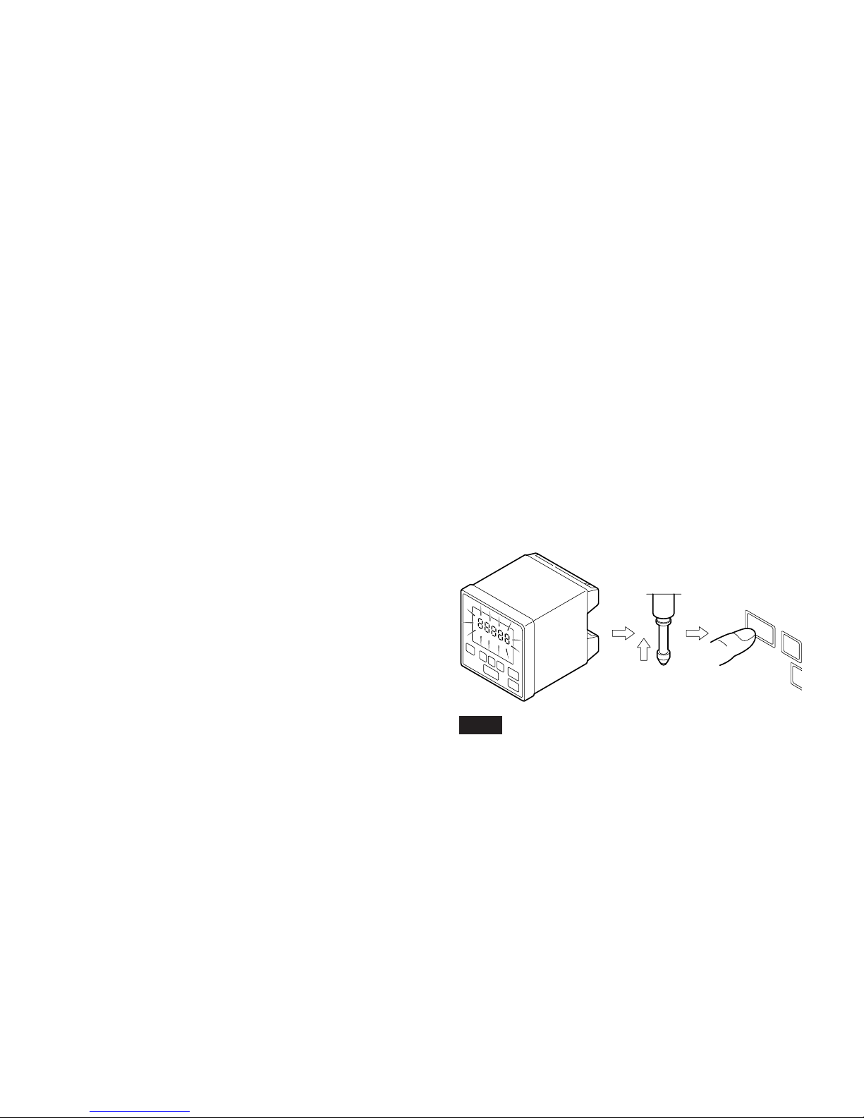
1-4. Instructions for connecting to
the measuring unit
• The LT10A/LT11A is a counter unit designed for the DT
series measuring unit.
• When the LT10A/LT11A is connected to a DT series and
turned on, the digits corresponding to the channel
connected may flash. This shows that initialization is
required to calibrate the new pairing of both device and
unit. Here you should move the measuring unit at least
1 mm, as shown in the figure, and then press the reset
key on the LT10A/LT11A corresponding to the channel.
The device will now return to its normal measuring state.
Note
Once this procedure has been carried out the digits will not
flash while the device is connected to that measuring unit,
even if the power is turned off.
• Place the counter unit more than 0.5 m (20") away from a
high voltage source, large current source, large power
relay, etc.
• For installation of the counter unit, avoid a location
exposed to chips, cutting oil, or machine oil. If
unavoidable, take adequate countermeasures.
• Do not put a vinyl cover directly over the counter unit or
put it in a closed container.
• The ambient temperature should be in the range of 0 °C
to 40 °C (32 °F to 104 ° F). Avoid exposure to direct
sunlight, hot air currents, or heated air.
1-3. Cautions on operation
Carry out the key operations or I/O (BCD, etc.) connections
and operations in line with the explanations given in the
appropriate sections. Failure to correctly operate this
device may result in a malfunction.
RESET
P
1 mm or more
(E) 3
LT10A / LT11A Series
2. Summary
2-1. Features
• Compact size suited to inclusion in systems.
DIN size (72 × 72 mm). Can be panel-mounted.
• Devices such as PLCs are connectable from the counter
unit.
Go/No Go output is standard to all models. Models
capable of BCD and/or RS-232C also outputs are
available.
• Resolution
LT10A series : 0.005 mm (0.0002")
LT11A series : 0.001 mm (0.0001")
• As well as the current value, maximum and minimum
values and peak-to-peak values can also be measured.
• Add/Sub calculation is standard feature (only for 2
channel models).
Can measure the widths or steps.
• Can carry out Go/No Go test on different lots. (BCD
output models.)
Four different upper and lower limits can be stored in
memory for the Go/No Go comparison.
• Power is compatible to DC 9 to 24V.
Provided via the power input connector.
Use a power cable less than 10 meters long.
The counter unit LT10A/LT11A series is designed to be
incorporated into assembly lines or jigs, and to be used for
measuring components or Go/No Go.
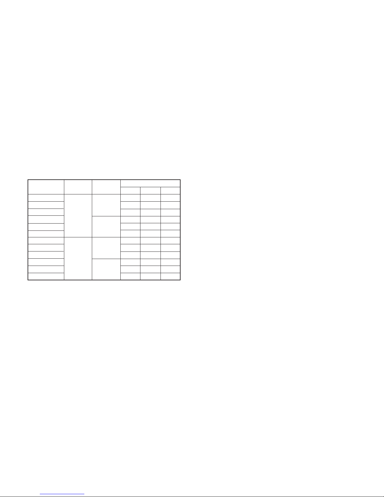
Use in combination with a DT series measuring unit. Types
are available to suit various uses.
Number of
input channel
1
2
1
2
Model
LT10A-105
LT10A-105B
LT10A-105C
LT10A-205
LT10A-205B
LT10A-205C
LT11A-101
LT11A-101B
LT11A-101C
LT11A-201
LT11A-201B
LT11A-201C
Output
Go/No Go
◯◯
◯◯
◯
◯◯
◯◯
◯
◯◯
◯◯
◯
◯◯
◯◯
◯
◯◯
◯◯
◯
◯◯
◯◯
◯
◯◯
◯◯
◯
◯◯
◯◯
◯
◯◯
◯◯
◯
◯◯
◯◯
◯
◯◯
◯◯
◯
◯◯
◯◯
◯
RS-232C
◯◯
◯◯
◯
◯◯
◯◯
◯
◯◯
◯◯
◯
◯◯
◯◯
◯
BCD
◯◯
◯◯
◯
◯◯
◯◯
◯
◯◯
◯◯
◯
◯◯
◯◯
◯
Resolution
(mm)
0.005
0.001
4 (E)
LT10A / LT11A Series
RESET
SET
P
MODE COMP
A
B
RESET
A
RESET
B
SET
P
MODE COMP
RESET
SET
P
MODE COMP
A
B
RESET
A
RESET
B
SET
P
MODE COMP
RESET
SET
P
MODE COMP
A
B
RESET
A
RESET
B
SET
P
MODE COMP
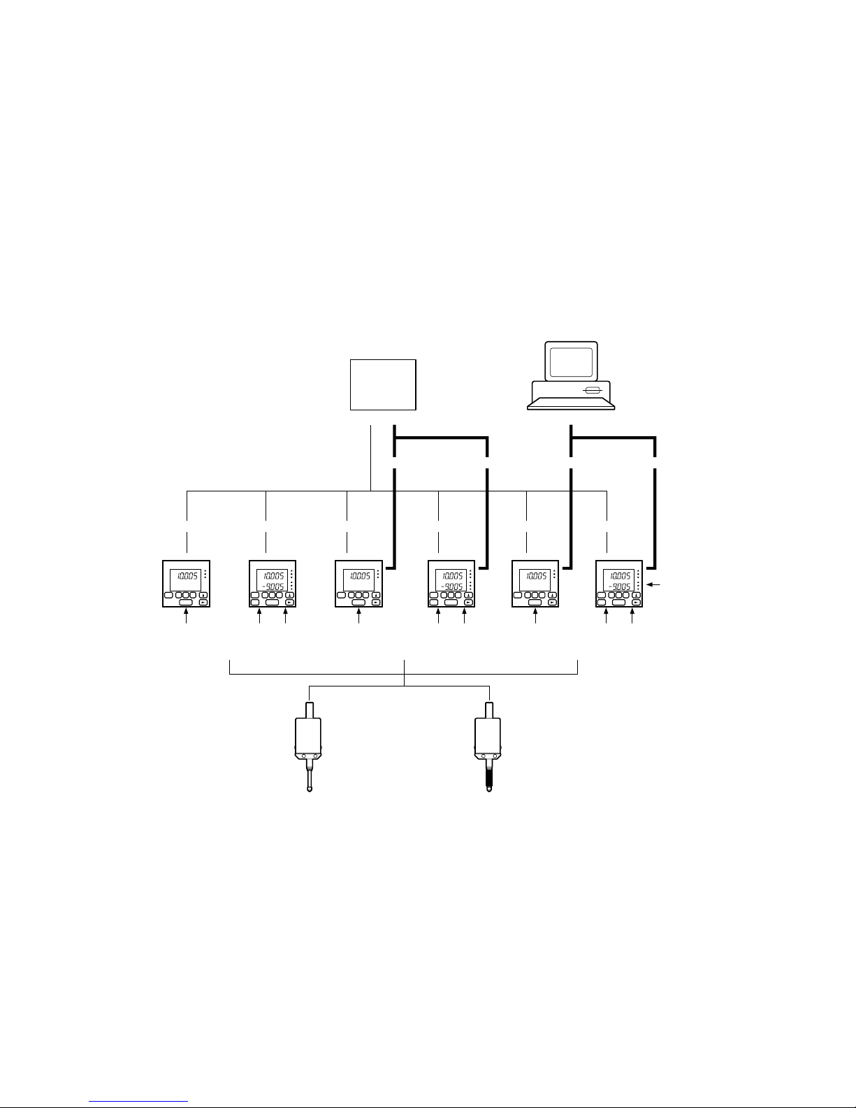
Go/No GoGo/No GoGo/No GoGo/No GoGo/No Go Go/No Go
PLC etc.
Computer
Counter unit
Measuring unit
LT10A-105
LT11A-101
1 CH
LT10A-205
LT11A-201
2 CH (including Add/Sub)
DT12N/512N
DT32N
DT12P/512P (IP64 Compatible)
DT32P (IP64 Compatible)
RS-232C RS-232CBCDBCD
LT10A-105B
LT11A-101B
1 CH
LT10A-205B
LT11A-201B
2 CH (including Add/Sub)
LT10A-105C
LT11A-101C
1 CH
LT10A-205C
LT11A-201C
2 CH (including Add/Sub)
Power source 9 to 24 V
(Power input connector.)
2-2. System structure
(E) 5
LT10A / LT11A Series
3-1. Connecting the cables
• Secure all connecting cables so as to prevent accidental
disconnection.
• Make certain the counter unit’s power is off before
connecting or disconnecting the measuring unit.
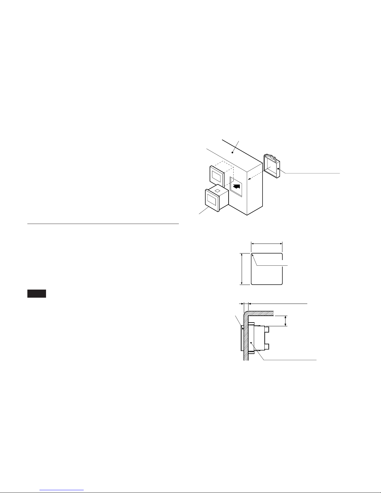
3-2. Installing the counter unit
When mounting in a panel
1. Cut out an opening to match the dimensions shown
(Fig. 2).
2. Insert the counter unit into the cut-out opening in the
panel from the front.
3. Attach the supplied counter stopper from the rear.
4. Press in the counter stopper until it touches the panel.
Note
When attaching the counter stopper to the counter unit,
leave enough space (min. 30 mm/1.18") between the top
and bottom. (Fig. 3)
3. Connecting and installating
Fig. 2
Fig. 3
Panel thickness: max. 12/0.47"
Cut-out dimensions
Panel box
Front of counter unit
68 /2.68"
+1.0
+0.4
+0.039"
+0.016"
68 /2.68"
+1.0
+0.4
+0.039"
+0.016"
4-R1 or less
Fig. 1
Counter stopper
(supplied)
Front of counter unit
Counter stopper
(supplied)
30/1.18"
30
6 (E)
LT10A / LT11A Series
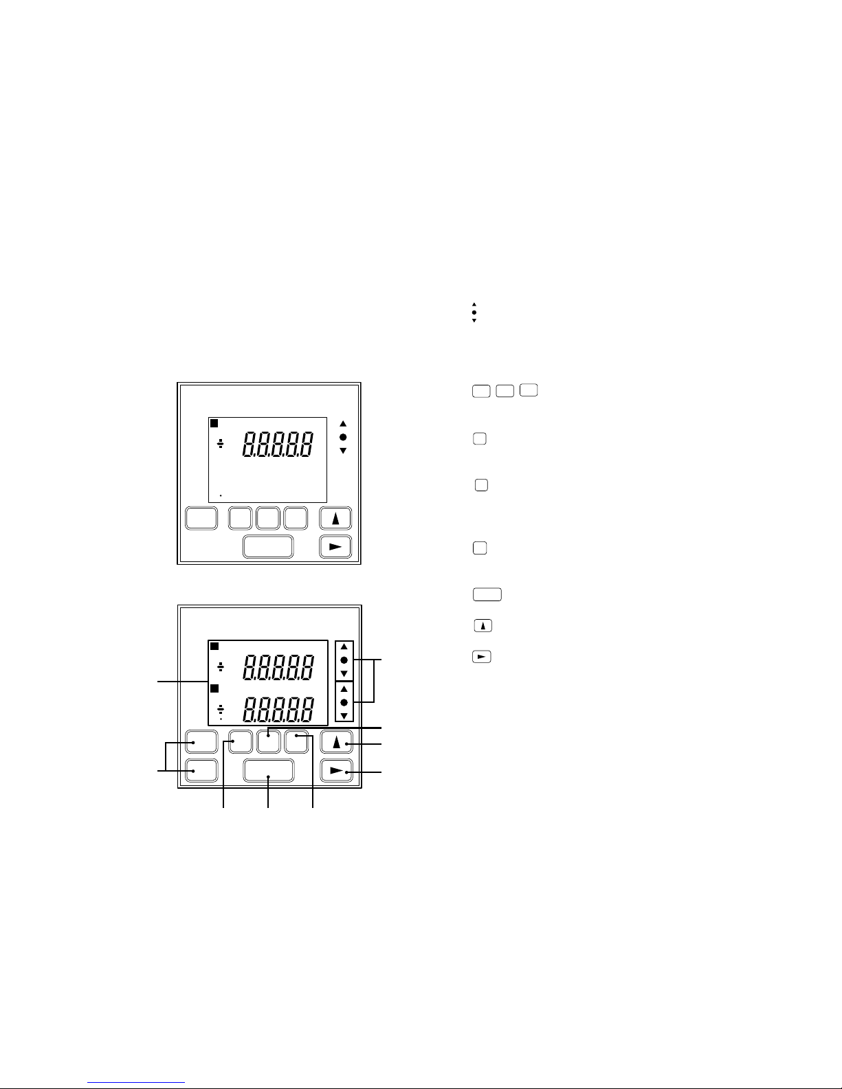
4-1. Front panel
4. Name and function of each part
q
: Go/No Go test result indicator
Gives the result of comparing the displayed value to
the comparator’s upper and lower limits. ∆ Over upper
limit, \ between upper and lower limit, ∇ under lower
limit.
w
RESET
RESET
A
RESET
B
: Reset key
• Resets the displayed value to zero.
• When a value has been preset it returns to this.
e
P
: Preset key
Enters the preset mode. (For the current value,
maximum value, and minimum value.)
r
MODE
: Measuring mode setting key
Key to enter the mode for selecting one of maximum,
minimum, peak-to-peak (maximum–minimum), or
current values.
t
COMP
: Comparator value setting key
Key to enter the mode for setting the comparator upper
or lower limit.
y
SET
: Setting key
Set a mode or a value.
u
: Number selection key
Selects the number for the digit chosen.
i
: Digit selection key
• Selects the digit to change when setting numeric
values.
• Normally, when it is held down for 5 seconds, key
lock is established; alternatively, if key lock is already
established, it is released.
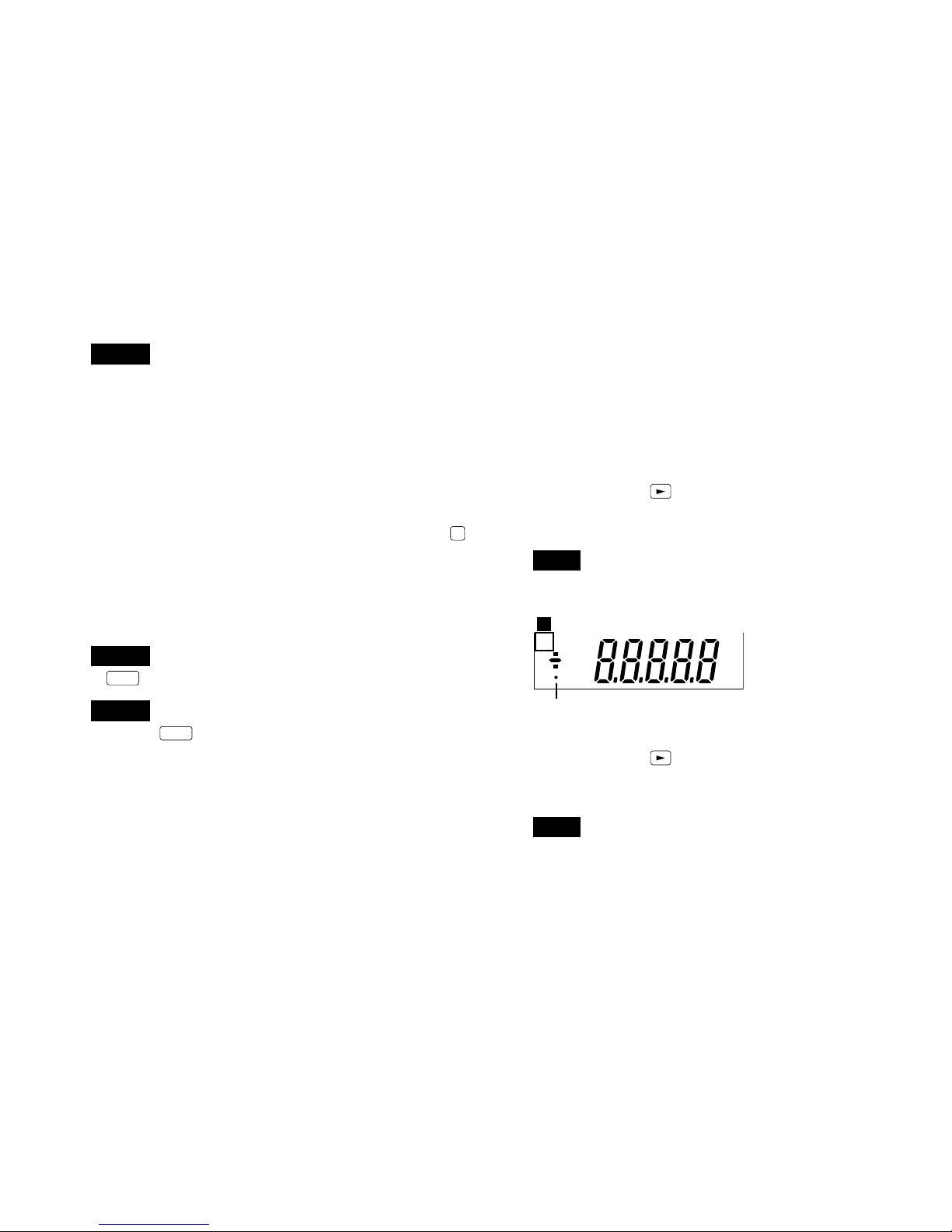
Main display
1 CH input model : LT10A-105/105B/105C
LT11A-101/101B/101C
2 CH input model : LT10A-205/205B/205C
LT11A-201/201B/201C
mm
M A X M I N P — P C P H1 2 3 4
P
RESET
SET
P
MODE COMP
q
r
u
i
tye
w
mm
M A X M I N P — P C P H1 2 3 4
P
RESET
SET
P
MODE COMP
mm
M A X M I N P — P C P L1 2 3 4
P
A+B
BA
A
RESET
B
(E) 7
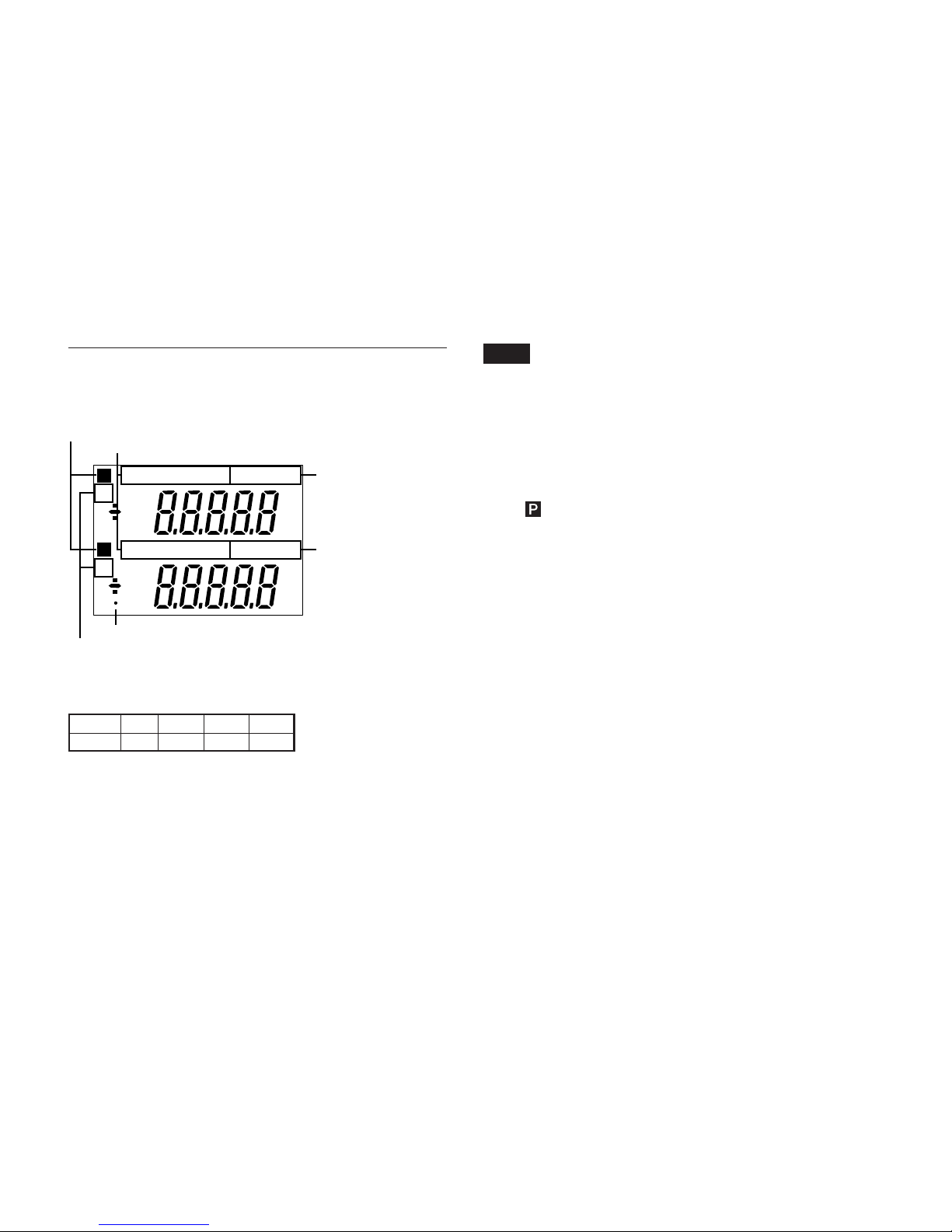
LT10A / LT11A Series
Note
• If upper display A+B and lower display A have been
selected, the comparator setting values of channel A will
be applied on both the upper and lower limits.
• When the upper display A+B is selected, the lower
display only shows the current value of the selected
channel and no operation can be made on the lower
display.
Preset status indicator
When
is displayed the preset value is set.
Peak-hold indicator
When MAX/MIN/P-P is displayed the data shown is the
maximum/minimum/maximum–minimum value.
When neither of the them is shown, the current value is
displayed.
Comparator upper limit setting indicator
Displayed when the comparator value has been set. The
upper digits are the upper limit.
Comparator lower limit setting indicator
Displayed when the comparator value has been set.
The lower digits are the lower limit.
• Up to four different comparator upper and lower limit
settings (CPH1 to CPH4 and CPL1 to CPL4) can be
stored in the memory for LT10A-105B/205B and LT11A101B/201B.
• LT10A-105/205/105C/205C and LT11A-101/201/101C/
201C have only one setting each.
Key lock indicator
Lighted when key lock is established; off when key lock is
released.
Comparator upper
limit setting indicator
Comparator lower
limit setting indicator
Peak-hold indicator
Preset status indicator
Main display
Displays the measured data, setting data for various
modes, or alarms, etc.
Selected channel indicator (2 channel model)
Choose one of these four.
• A:data from measuring unit,
input channel A
B:data from measuring unit,
input channel B
A+B: sum of data from channel A and B
• In order to carry out calculations such as A–B or –A+B,
change the direction of A or B to “+” or “–”.
(Initial settings)
Upper AA+BA+BA+B
Lower BA B –
Selected channel indicator
Key lock indicator
mm
M A X M I N P — P C P H1 2 3 4
P
mm
M A X M I N P — P C P L1 2 3 4
P
A
B
8 (E)
LT10A / LT11A Series
q Power input connector
Connected to the external power supply (+9 V to +24 V
DC).
Use a power cable less than 10 meters long.
Connector used : MC1.5/3-ST-3.5 (provided) made
by Phoenix Contact
w I/O connectors→See “6. I/O connector”.
There are three kinds of I/O connectors: one type is
used for channel A, one for channel B and one for both
channels A and B.
Input : Reset, Peak-hold start, Peak-hold pause, RS
trigger.
Output: Go/No Go output.
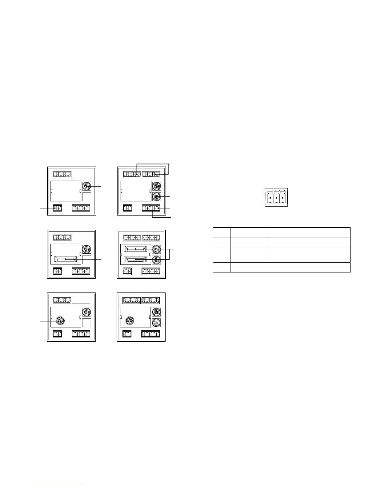
4-2. Rear panel
7 6 5 4 3 2 1 7 6 5 4 3 2 1
1 2 3 4 5 6 7
AB
SIG. IN A
SIG. IN B
FG +V 0V
DC IN
7 6 5 4 3 2 1 7 6 5 4 3 2 1
1 2 3 4 5 6 7
AB
SIG. IN A
SIG. IN B
FG +V 0V
DC IN
7 6 5 4 3 2 1 7 6 5 4 3 2 1
BCD OUT
1 2 3 4 5 6 7
AB
SIG. IN A
SIG. IN B
FG +V 0V
DC IN
RC-232C
7 6 5 4 3 2 1 7 6 5 4 3 2 1
1 2 3 4 5 6 7
AB
SIG. IN A
SIG. IN B
FG +V 0V
DC IN
7 6 5 4 3 2 1 7 6 5 4 3 2 1
BCD OUT. B
BCD OUT. A
1 2 3 4 5 6 7
AB
SIG. IN A
SIG. IN B
FG +V 0V
DC IN
RC-232C
7 6 5 4 3 2 1 7 6 5 4 3 2 1
1 2 3 4 5 6 7
AB
SIG. IN A
SIG. IN B
FG +V 0V
DC IN
1 channel-models 2 channel-models
LT10A-105, LT11A-101 LT10A-205, LT11A-201
LT10A-205B, LT11A-201BLT10A-105B, LT11A-101B
LT10A-105C, LT11A-101C LT10A-205C, LT11A-201C
Common I/O
connector
q
e
t
u
r
w
y
w
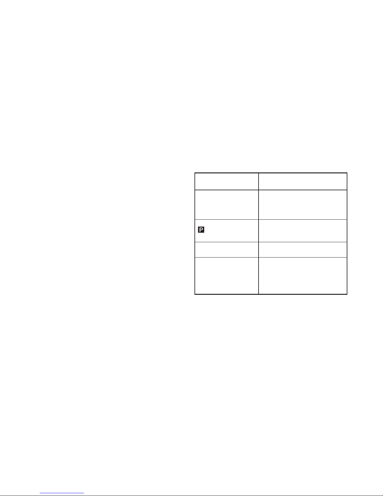
FG +V 0V
DC IN
No. 1 2 3
No.
1
2
3
Signal name
FG
+ V
0 V
Signal
Frame ground
Main DC power
(+9 V to +24 V) input
GND for power
(E) 9
LT10A / LT11A Series
e Measuring unit input :SIG. IN A
r Measuring unit input : SIG. IN B (2 channel models)
ty BCD Output
With the 2 channel models the upper and lower
selections of the front panel’s main display correspond
to the BCD OUT. A/BCD OUT. B. So if “A+B” is
selected the output is to BCD OUT. A.
The following operations are possible when BCD
input/output terminal is used.
Input : Comparator value selection (4 settings),
measuring mode (current value, maximum value,
minimum value, peak-to-peak values) selection
Output: 5 digits
Outputs one of the current, maximum,
minimum, and peak-to-peak values selected
via the keys on the front panel and the
external input.
Alarm output
u RS-232C interface
(See “8. RS-232C Interface”.)
Reset, peak-hold start, setting/recall of preset values,
setting the comparator value, selecting and outputting
the current value/maximum value/minimum value/
peak-to-peak value.
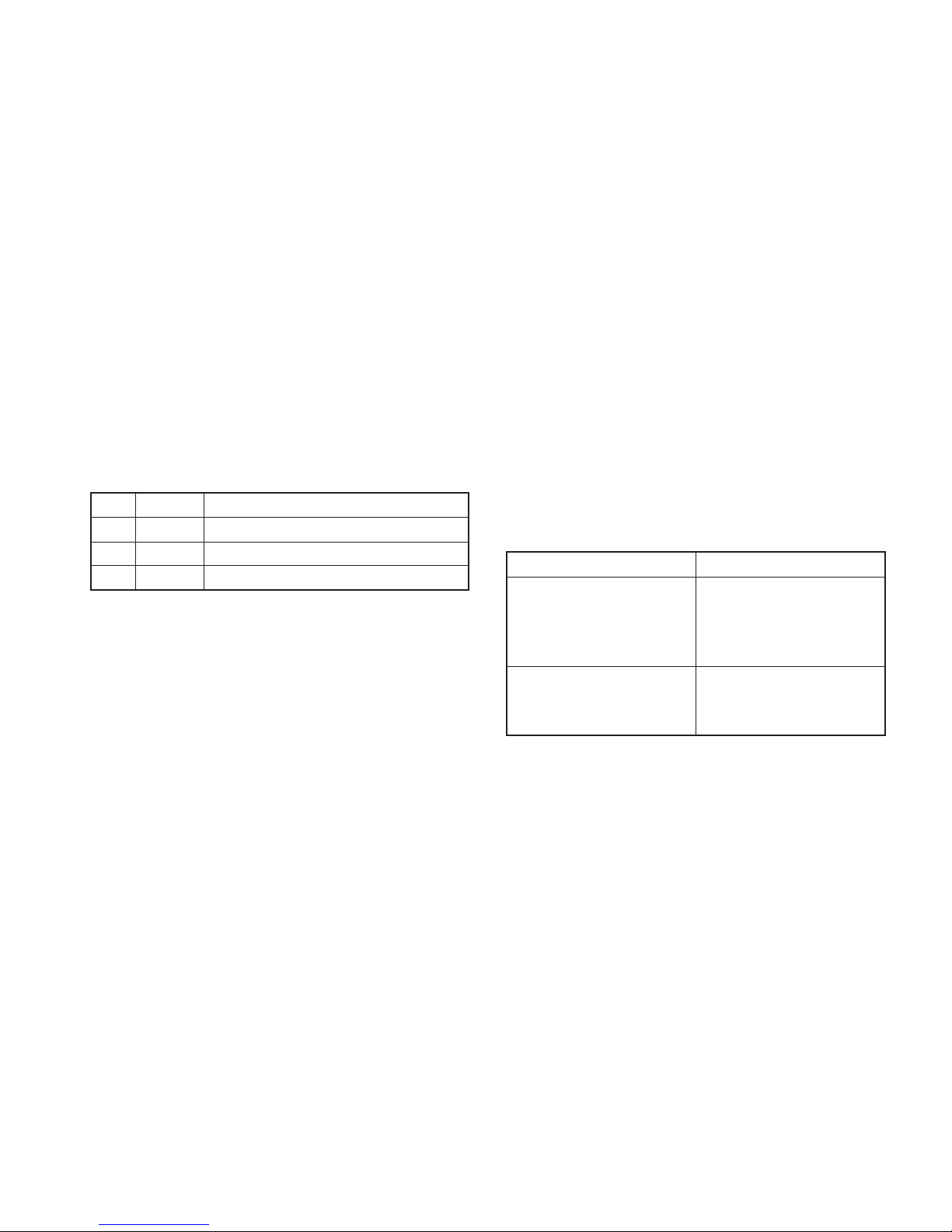
4-3. Function description
4-3-1. Reset key
Counter unit
Measuring mode
(Current value, maximum
value, minimum value,
peak-to-peak value)
Preset mode
(
and the selected digit
will flash.)
“Error” is displayed
All the numbers for the
channel with an error
flash.
Operation performed when reset
key is pressed
Display is set to zero.
When a preset value has been set, it
is recalled.
Preset value is set to zero.
“Error” is canceled and then returnes
to the measuring state.
Automatically carries out initialization
to calibrate the device to a new
measuring unit. (Before resetting the
measuring unit must be moved at
least 1 mm.)
4-3-2. Preset functions
• It is possible to set preset values for each of the current,
maximum, and minimum value measuring modes.
• For instructions on setting the preset value, please refer
to P18, “5-2-1. Setting the preset value.”
10 (E)
LT10A / LT11A Series
4-3-4. Peak-hold function
• Stores the maximum, minimum, and peak-to-peak
(maximum–minimum) values of the measured values.
• The above mentioned measuring mode is set using the
keys on the front panel.
• The device starts storing values either when a start signal
is supplied to the start/latch pins (channel A: pin w,
channel B: pin r) of the lower 7-pin I/O connector
(common) (See “6. I/O connector”.) or when the reset key
has been pressed.
4-3-3. Result evaluation
• Go/No Go test is carried out by comparing data from the
current measuring mode (current value, maximum value,
minimum value, or peak-to-peak value) to the comparator
upper and lower limits.
• This result is displayed on the front panel and output from
the I/O connector (See “6. I/O connector”.).
Result
High
Go
Low
Display
>
\
?
=
Condition
Data > upper limit
Upper limit > data > lower limit
Lower limit > data
=
Operation
I/O connector (common) A CH:
starts on “L” (ON) signal from pin
w; I/O connector (common) B
CH: starts on “L” (ON) signal
from pin r.
Reset key is pressed
Result
Starts storing from the current
value.
Starts storing from zero.
When a preset value is set the
device starts storing from the
preset value.
(E) 11
LT10A / LT11A Series
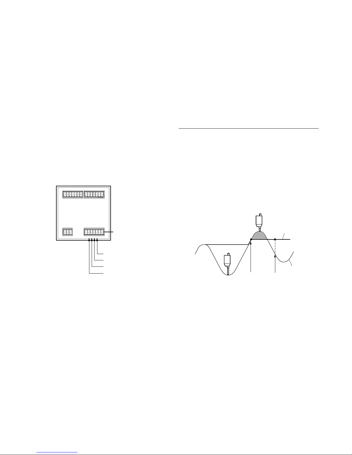
4-3-5. Peak-hold pause function
• Pause the storing of the maximum, minimum and peakto-peak (maximum-minimum) values of the measured
values.
• When the peak-hold function is to be paused, set the
pause pin of the lower 7-pin I/O connector (common) to
ON; to resume storing, set it to OFF.
Maximum value
Current value
Pause ON Pause OFF
Peak value data update stop (pause)
When pause is ON
The peak value updating is stopped. The current value is
constantly updated.
If the maximum value mode, minimum value mode or peakto-peak value mode is set as the measuring mode, the Go/
No GO judgment output and the output data are not
updated even when the measuring unit is operated.
When pause is OFF
The peak values are constantly updated.
7 6 5 4 3 2 1 7 6 5 4 3 2 1
1 2 3 4 5 6 7
DC IN
PAUSE (B)
START (B)
PAUSE (A)
START (A)
Common
I/O connector
w
e
r
t

12 (E)
LT10A / LT11A Series
4-3-6. Latch functions
In the current value mode, this function holds output data
and Go/No GO output for that value.
[Latch conditions]
• The start input signal is set as the latch input by the
parameter setting.
• Current value mode
Note
This function does not operate when the measuring mode
is peak value mode.
Current value
Latch OFF
Latch ON
LT10A / LT11A Series
(E) 13
5. Operation
This sections uses the 2 channel model in its explanations.
The 1 channel model is the same as the 2 channel model
without the B channel.
BCD and RS-232C models are noted in the text.
5-1. Initial settings
An initialization is carried out at the time of shipping;
however it is possible to make the following selections
depending on intended use. Details of the settings at the
time of shipping are given in each section.
• Changing between inches/mm
Turn on power while holding down
RESET
A
and press
MODE
key.
Press
to change between inches/mm.
Press
SET
to set and return to the measuring state.
• Device is set to mm at the time of shipping.
• To change the initial settings hold down the
SET
key and
press the
MODE
key for approximately 2 seconds.
Basic operation
MODE
: to the next item.
: Select item.
SET
: Set item.
Note
• Even if you select an item with the
key, no changes
will be mode until you press the
SET
key.
• Once the initial setting mode has been entered it is not
possible to return to the measuring state partway
through. Press the
MODE
key repeatedly to skip the items.
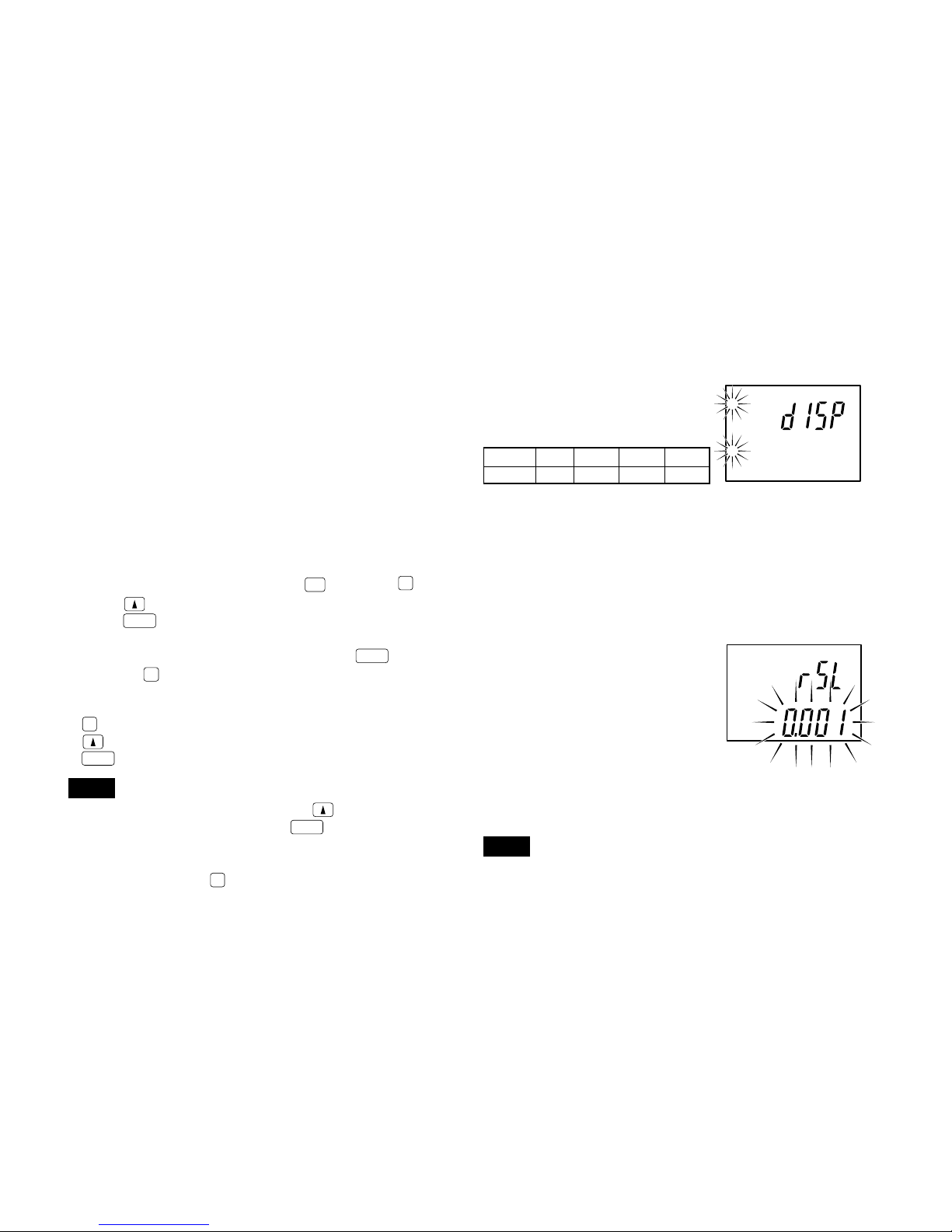
5-1-1. Basic settings
1. Setting the display
(2 channel models)
One of the following may be
chosen:
When the upper display A+B is
selected, the lower display only
shows the current value of the
selected channel and no
operation can be made on the
lower display.
2. Setting the display resolution or direction
(channel A)
0.001/0.005/0.01/–0.001/–0.005/
–0.01 mm
• With the measuring unit’s
spindle pushed in:
+: positive direction
–: negative direction
∗ When set to inches, values are chosen from 0.0002,
0.0005, –0.0002, and –0.0005.
Note
With the LT10A series, 0.001 mm and –0.001 mm (0.0001"
and –0.0001") are not avaible.
Upper AA+BA+BA+B
Lower BA B –
factory-set
factory-set (LT11A)
A
A
B
LT10A / LT11A Series
14 (E)
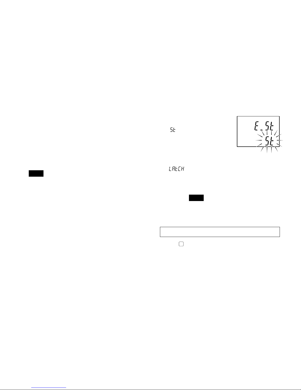
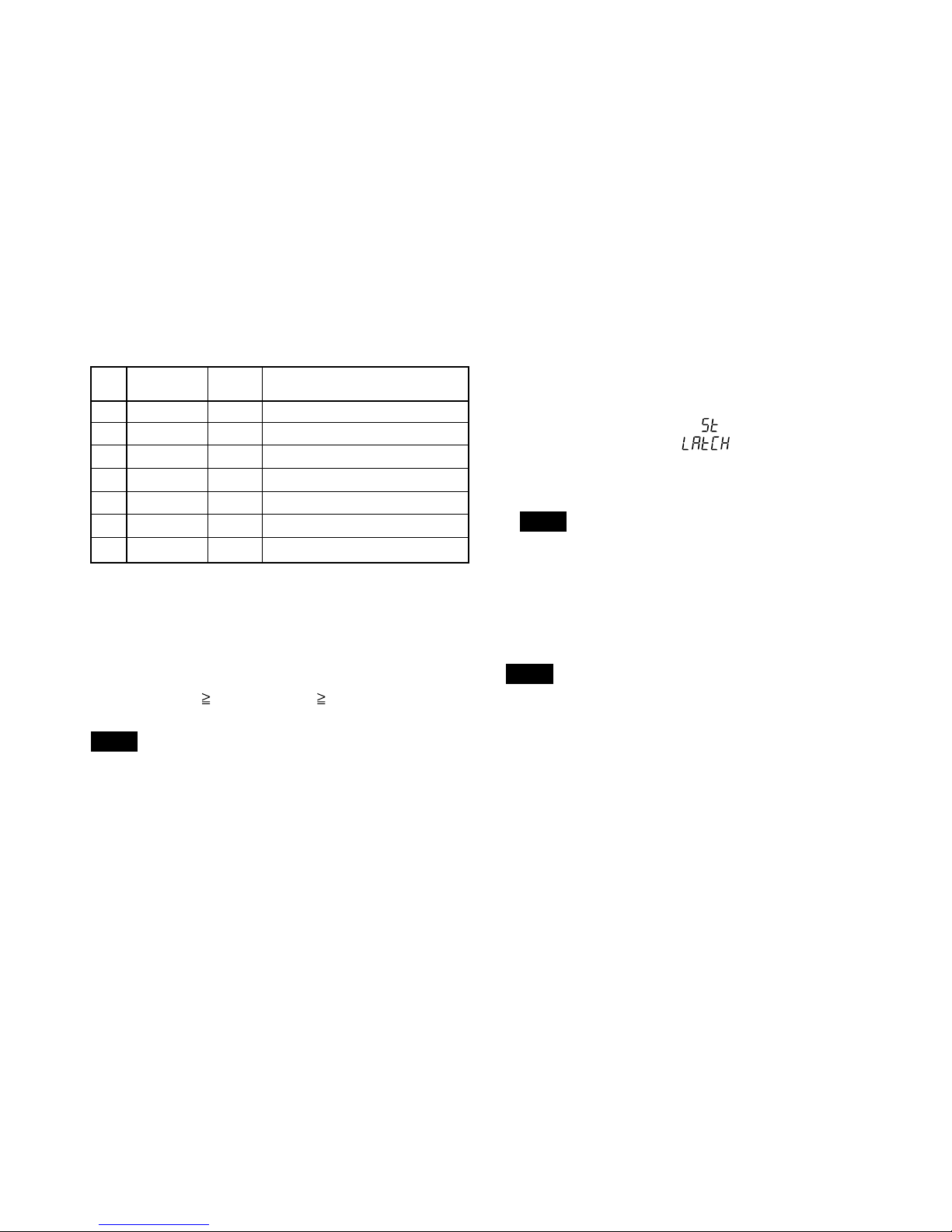
4. Selecting the start input terminal (I/O connector)
function
(See “6. I/O connector”.)
:
Start function
Setting this terminal
to “L” (ON) sets the
peak-hold value to
the current value and
restarts the storing
procedure.
: Latch function
When using the current value measuring
mode, setting this terminal to “L” (ON) stores
the output and display of the Go/No Go
comparison at that point in time.
Note
When the latch is ON, display and Go/No Go
output storage by the DRQ input for the BCD
model and RS-TRG input for the RS-232C
model is invalidated.
Initial settings are now complete for the standard model.
Pressing
MODE
.. Standard model → Returns to the measuring
state.
BCD model → Go to section 5-1-2.
RS-232C model → Go to section 5-1-3.
3. Setting the display resolution or direction
(channel B, 2 channel models)
0.001/0.005/0.01/–0.001/–0.005/–0.01 mm.
• With the measuring unit’s spindle pushed in:
+: positive direction
–: negative direction
• When displaying A+B:
If you set the direction of A to “–” the data displayed is
the calculation “–A+B”.
The same can be done with B.
Note
• With the LT10A series, 0.001 mm and –0.001 mm
(0.0001" and –0.0001") are not avaible.
• When the addition A+B is chosen the direction for B can
be selected, but its resolution will be the same as that of
A.
factory-set
LT10A / LT11A Series
(E) 15
5-1-2. BCD model
(only LT10A-105B/205B, LT11A-101B/
201B)
Proceeds to the next setting mode from “5-1-1. Basic
settings” step 4.
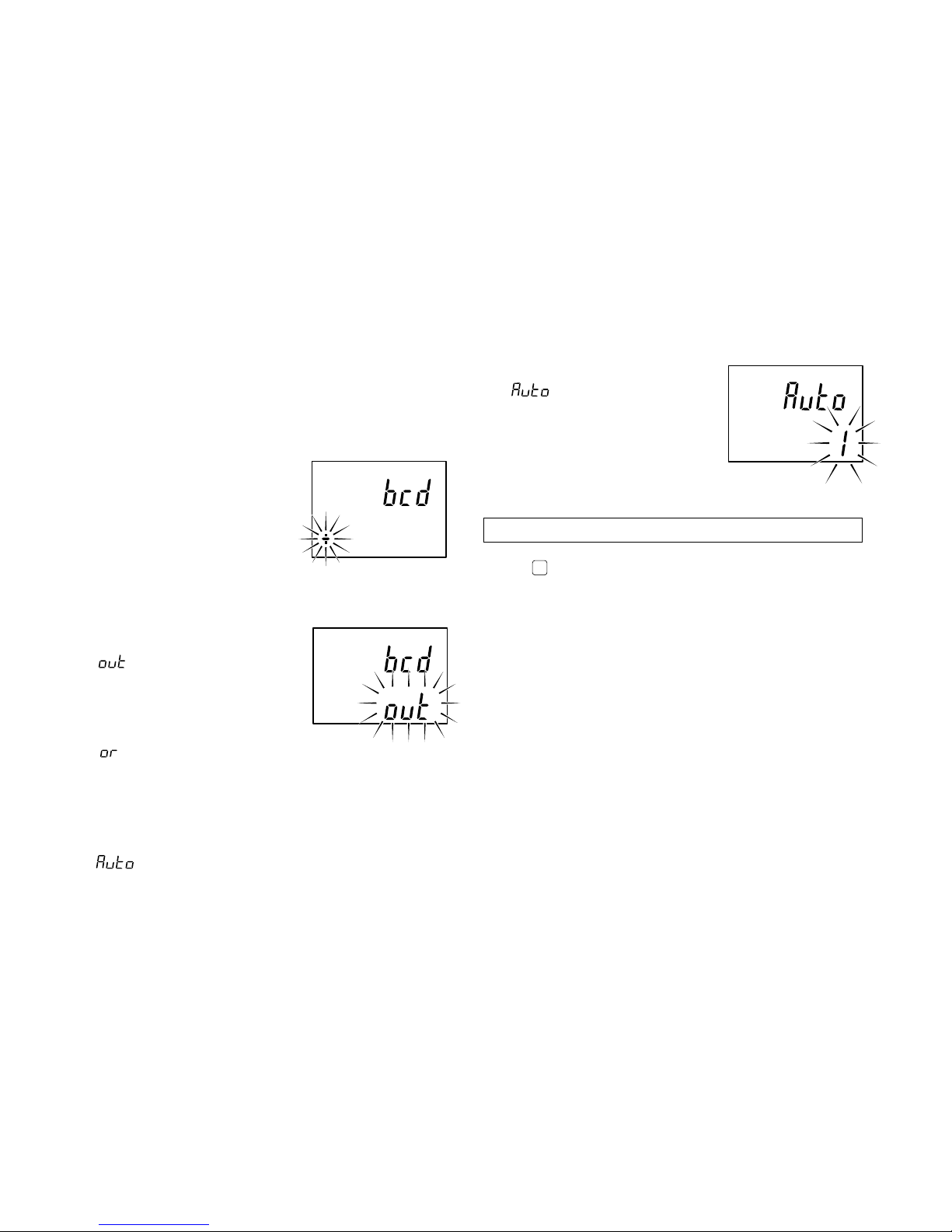
1. BCD logic
Setting the BCD output logic.
“+” is true logic.
“–” is false logic.
Exception : Logic for the DRQ,
READY, and alarm
terminals cannot be
changed.
(See “7. BCD output”)
2. BCD output format
Setting the BCD output format.
:BCD is output
according to the DRQ
signal input, and the
resulting status is held
even if the DRQ signal
goes off.
:BCD is output
according to DRQ
signal input, and
assumes highimpedance status
when there is no DRQ
signal input.
: BCD is output at all times at the set time interval
without the input of the DRQ signal.
factory-set
factory-set
factory-set
3. Automatic BCD output time interval
This mode is established when
has been set in step 2.
Select one of the eight time
intervals listed below.
1/2/4/8/16/32/64/128 ms
(See “7-2. Signal timing” for the
BCD input/output timing)
Initial settings are now complete for the BCD model.
Press
MODE
to return to the measuring state.

LT10A / LT11A Series
16 (E)
: Outputting with measuring mode information
and comparator Go/No Go result
1st byte : Channel name (A or B)
2nd byte : Current mode
(N: Current value,
P: Peak-to-peak value,
I : Minimum value,
A: Maximum value)
3rd byte : Unit (M: mm, I: inch)
4th byte : Comparator Go/No Go
result
U : Upper limit over
G : Within range
L : Lower limit under
E : When an alarm has
occurred
5th byte : Sign (“+”
or “–”)
6th to 11th bytes
: Numerical data
(ex.00.000)
: Outputting according to the mode 1 format
(statistical calculations) of the digital
printer P40 (End of sales).
Whether, with the 2 channel model, to
output B channel data following a
space or to divide it with the
delimiter is selected by step 9.
(except for P40 mode)
Note
When set to mode even the
2 channel model only outputs the A
channel.
: (“+” or space)
factory-set
5-1-3. RS-232C model
(only LT10A-105C/205C, LT11A-101C/
201C)
Proceeds to the next setting mode from “5-1-1. Basic
settings” step 2.
1. Setting the output data format
: Normal output
1st byte : Channel name (A or B)
2nd byte : Sign (“+”
or “–”)
3rd to 8th bytes: Numerical data
(ex.12.345)
: Outputting with measurement mode
information
1st byte : Channel name (A or B)
2nd byte : Current mode
(N: Current value,
P: Peak-to-peak value,
I : Minimum value,
A: Maximum value)
3rd byte : Unit (M: mm, I: inch)
4th byte : Sign (“+”
or “–”)
5th to 10th bytes
: Numerical data
(ex.00.000)
LT10A / LT11A Series
(E) 17
factory-set
factory-set
factory-set
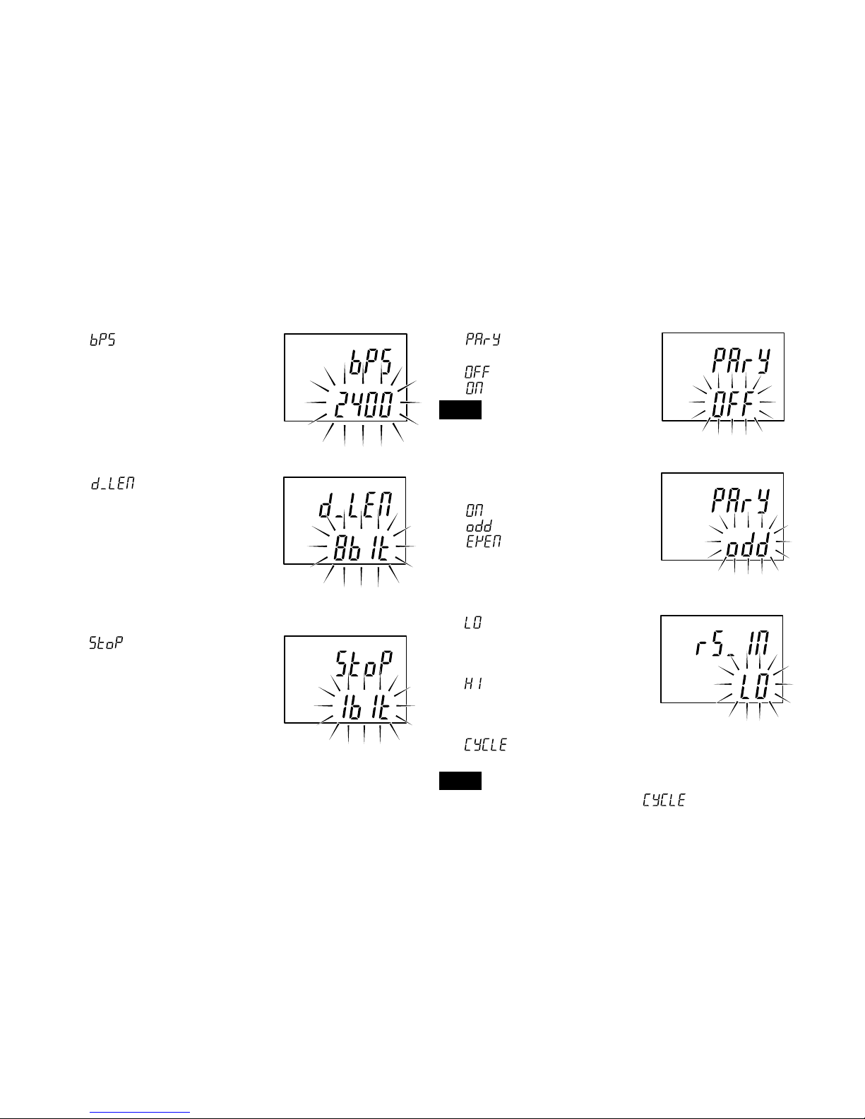
2. Setting the data signalling rate
is displayed and the data
signalling rate can be selected.
600/1200/2400/4800/9600/
19200/38400 bps
3. Setting the data length
is displayed and the
data can be set to 7 or 8 bits.
4. Setting the stop-bit
is displayed and the stop
bit can be set to one or 2 bits.
5. Setting the parity
is displayed and the
parity can be switched on or off.
: No parity
: Parity
Note
When the data length is set to 7 bits
in step 3, select “Parity”.
6. Selecting odd or even parity
Switches to this mode when
is chosen above.
: Odd parity
: Even parity
7. Selecting the function for the RS-TRG terminal
:Mode for inputting
mechanical contact
outputs (such as relay
and switch outputs).
:Mode for inputting
electronic circuit
outputs (such as
transistor outputs).
:To output at a set
interval.
Note
The RS-TRG input cannot be used when
has been selected.
factory-set
factory-set
factory-set
LT10A / LT11A Series
18 (E)
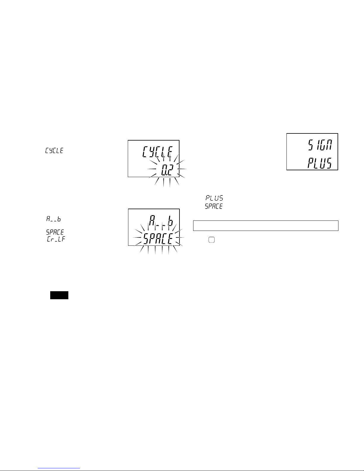
8. Selecting the output time interval.
This mode is selected when
has been chosen in
step 7.
One of the following eight
intervals can be chosen.
0.2/0.5/1.0/5.0/10/30/60/300 s
9. Selecting the data transmission format
(2 channel models)
is displayed and one of
the following is chosen.
: format (a) given below
: format (b) given below
• To output from channel A –12.345, and from channel
B 67.891:
(a) A–12.345MB+67.891
C
R
L
F
(b) A–12.345
CR L
F B+67.891 CR LF
Note
M means a space.
factory-set
factory-set
10. Plus sign setting of the
output data
When the output data is
positive, output characters will
be set as a plus sign.
This setting will also be
reflected in the input data
(preset value, comparator
value).
: Outputs plus as a sign.
: Outputs space as a sign. (compatible to
previous model)
Initial settings are now complete for the RS-232C model.
Press
MODE
to return to the measuring state.
factory-set
LT10A / LT11A Series
(E) 19
5-2. Various settings
In the setting modes there is always an indicator flashing in
the main display.
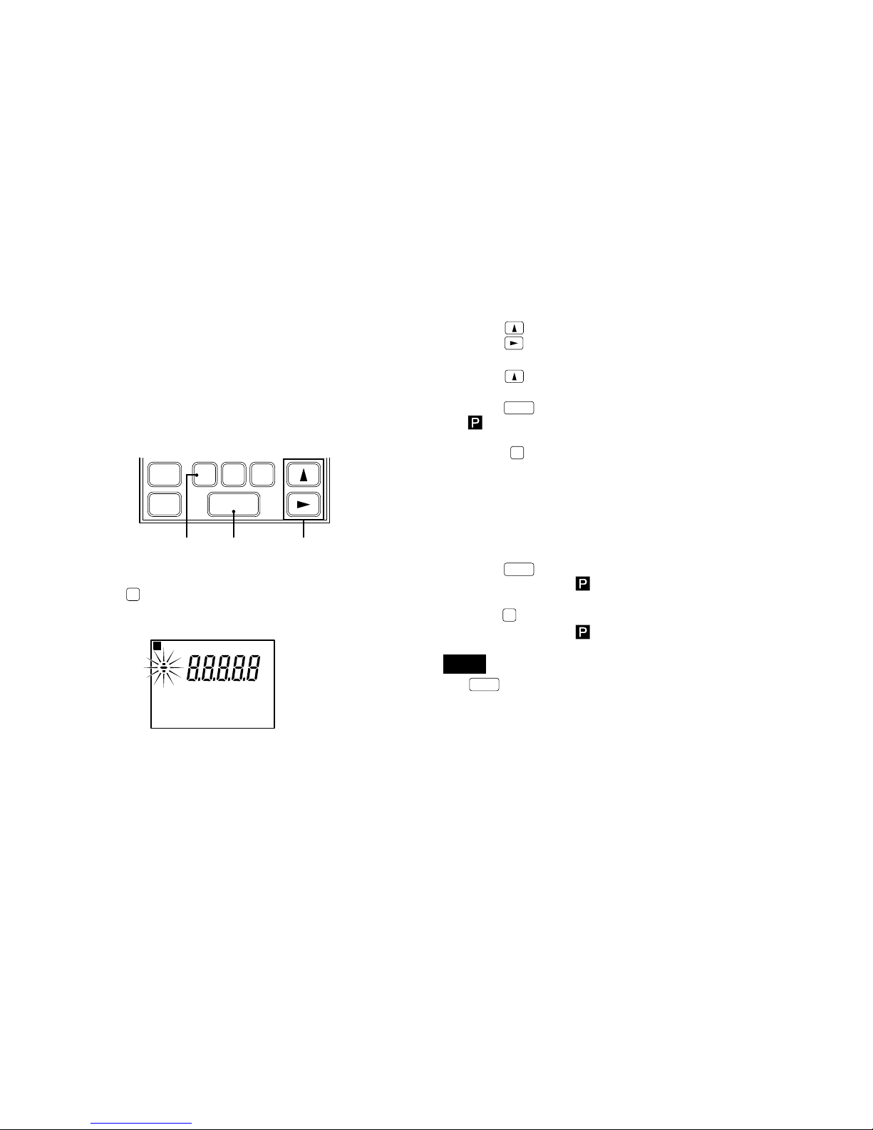
5-2-1. Setting the preset value
1 Push
P
to select.
The A channel preset value setting mode.
SET
P
MODE COMP
1, 4, 7 3, 6 2, 5
RESET
B
RESET
A
P
A
2 Push to select a sign.
Push
to select a digit to be set.
The selected digit flashes.
Push
to select a numeral.
3 Push
SET
to set.
for A channel flashes.
4 Push
P
to select B channel preset value setting
mode.
B channels sign flashes “+”.
Single channel models return to the measuring state.
5 Same as 2.
6 Push
SET
to set.
Both A/B channel
flashes.
7 Push
P
to returns to the measuring state.
Both A/B channel
lights.
Note
• If
SET
is not pressed the previous setting is kept.
• If the maximum value mode, minimum value mode or
peak-to-peak value mode is set as the measuring mode,
the peak value of each mode has been set is set to the
preset value when the preset value is set to the value
which has more than the peak value.
LT10A / LT11A Series
20 (E)
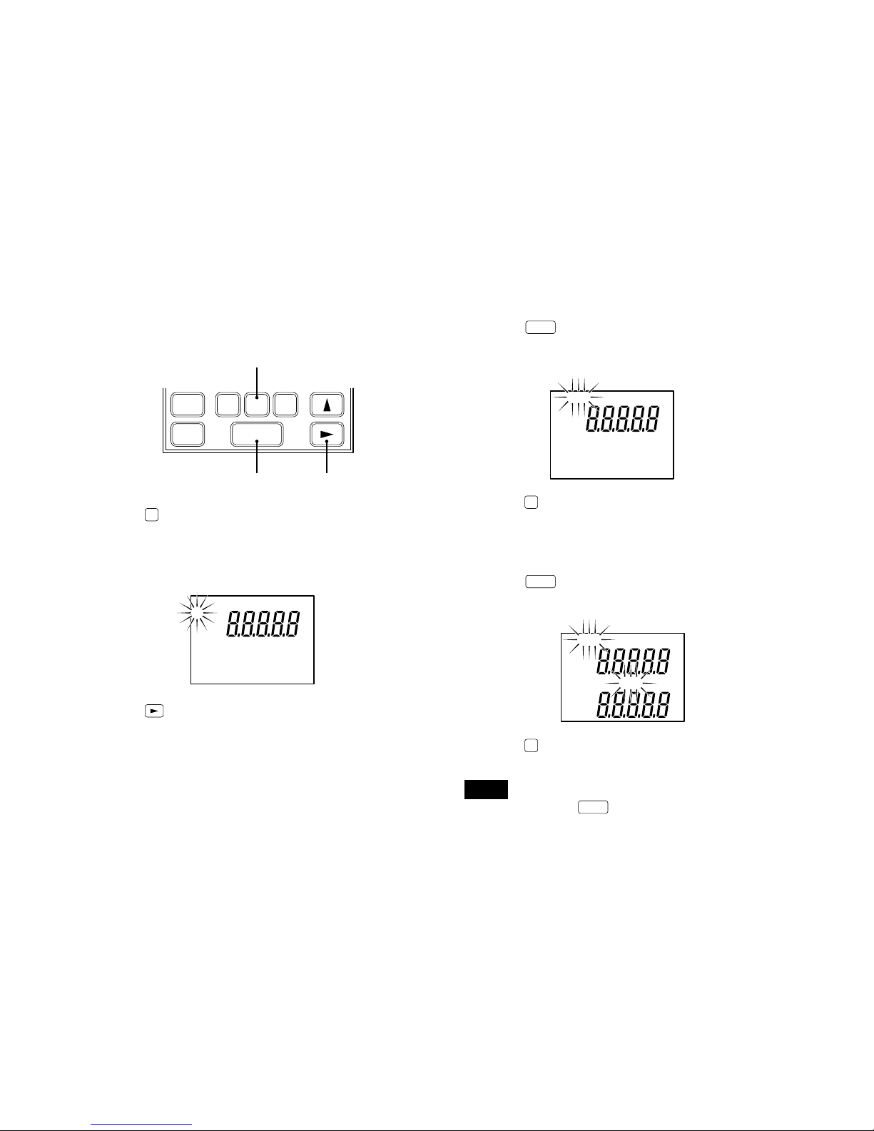
3 Push
SET
to set.
Set mode flashes.
The other channel A modes disappear.
4 Push
MODE
to select the setting mode for channel B.
Currently set channel B mode flashes.
5 Same as 2.
6 Push
SET
to set.
Modes set for channels A and B flash.
7 Push
MODE
to return to the measuring state.
Modes set for channels A and B light.
Note
If you do not press
SET
the previous settings will be kept.
M A X AM A X
P ―P
A
B
5-2-2. Setting the measuring mode
1 Push
MODE
to select the mode for setting a measuring
mode (current value, maximum value, minimum value,
or peak-to peak value) for channel A.
∗ Each of there modes are indicated “A”, “MAX”, “MIN”
and “P-P”, respectively.
2 Push
to select a measuring mode.
The selected mode’s indicator flashes.
3, 6 2, 5
1, 4, 7
SET
P
MODE COMP
RESET
B
RESET
A
M A X M I N P ―P
A
LT10A / LT11A Series
(E) 21
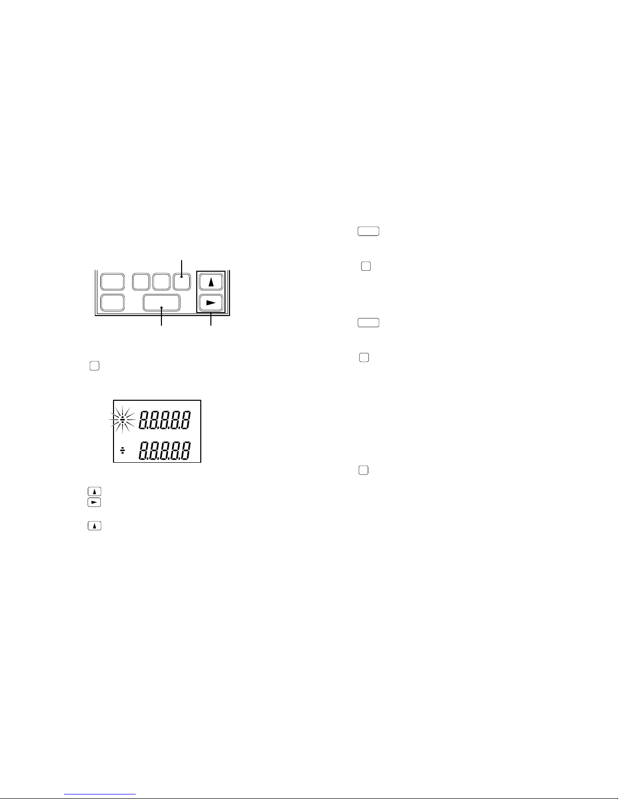
5-2-3. Setting the comparator values
1 Push
COMP
to select the mode for setting the channel A
comparator values. Start from the CPH (comparator
upper limit) setting.
2 Push
to select a sign.
Push
to select digits.
A selected digit flashes.
Push
to select a number.
RESET
SET
P
MODE COMP
A
RESET
B
3, 6, 9, 12 2, 5, 8, 11
1, 4, 7, 10, 13
C P H
C P L
A
3 Push
SET
to set.
“CPH” flashes.
4 Push
COMP
to select the CPL comparator lower limit
setting mode. Sign of the CPL value flashes.
5 Same as 2.
6 Push
SET
to set.
“CPH” and “CPL” flash.
7 Push
COMP
to select the mode for setting the channel B
comparator values.
∗ Single channel models return to the measuring state.
8
9
10 Same as 2, 3, 4, 5, 6.
11
12
13 Push
COMP
to return to the measuring state.
LT10A / LT11A Series
22 (E)
5-2-4. Setting the key lock
Set the key lock to invalidate the key operations. This
stores the displayed values or set values should a key is hit
by accident. The key lock can be set during normal
operations.
Setting
1. Press and hold
(for about 5 seconds). Keep
pressing until the key lock indicator in the main display
changes from flashing to on.
Note
The setting is not performed unless the key is pressed
while the indicator is flashing.
Release
1. Press and hold
(for about 5 seconds). Keep
pressing until the key lock indicator in the main display
changes from flashing to off.
Note
The release is not performed unless the key is pressed
while the indicator is flashing.
Key lock indicator
mm
M A X M I N P — P C P L1 2 3 4
P
B
Note 1
With the BCD models four different settings can be stored
in memory. The operations are as follows.
A CH CPH1 CPH2 CPH3 CPH4
CPL1 CPL2 CPL3 CPL4
↓↓↓↓
B CH CPH1 CPH2 CPH3 CPH4
CPL1 CPL2 CPL3 CPL4
• When the 4 settings are not required press
COMP
repeatedly.
• Changing the 4 different setting values is carried out via
the BCD connector input terminal.
• When the BCD connector is not connected the setting is
CPH1 and CPL1.
Note 2
If
SET
is not pressed the previous setting is maintained.
Note 3
When the
SET
key is pressed to set the CPL the sign (“+”
or “–”) of the CPH value may flash. This is because the CPH
(upper limit) is less than the CPL (lower limit), and the
device is in the CPH setting mode. In this case, return to
and start from the CPH setting.
→
→
→

LT10A / LT11A Series
(E) 23
6. I/O connector
The I/O connector on the rear panel of the counter unit has
functions for Go/No Go output based on the comparator
function, start input, pause input, RS-232C trigger input and
reset input.
6-1. Connector pin assignment
Rear of counter unit
• Use a shielded cable for connection to the FG pin on the
rear of the counter unit.
(Prepare a shield cable by yourself.)
Connector used : MC1.5/7-ST-3.5 (provided) made
by Phoenix Contact
Outer cover
Knitted shield
Cross section of the cable
Signal
(See “4-3. Function description”.)
I/O connector A
Pin Signal
IN/OUT Signal
No. name
1 GND –
2NC – Connection prohibited
3 RESET (A) IN Reset input (A CH)
4 LO (A) OUT Go/No Go output Low (A CH)
5 GO (A) OUT Go/No Go output Go (A CH)
6 HI (A) OUT Go/No Go output High (A CH)
7 GND –
I/O connector B (not provided for 1-channel models)
Pin Signal
IN/OUT Signal
No. name
1 GND –
2NC – Connection prohibited
3 RESET (B) IN Reset input (B CH)
4 LO (B) OUT Go/No Go output Low (B CH)
5 GO (B) OUT Go/No Go output Go (B CH)
6 HI (B) OUT Go/No Go output High (B CH)
7 GND –
7 6 5 4 3 2 1 7 6 5 4 3 2 1
1 2 3 4 5 6 7
AB
FG +V 0V
DC IN
I/O connector BI/O connector A
Power input
connector
Common
I/O connector
LT10A / LT11A Series
24 (E)
Start/latch input
• The “L” (ON) signal sets the maximum, minimum, and
peak-to-peak values to the current value and restarts
their storing. (Start function)
• If, when the initial setting of
which was set at the time
of shipping is changed to
, the current value mode
serves as the measuring mode, the “L” (ON) signal will
hold the Go/No Go output (I/O connector) and display.
(Latch function)
Note
While the Go/No Go output is at the “L” level, reset/preset
value recall cannot be effected by reset key or external
reset/preset value recall input.
Reset input
“L” (ON) sets the measured value to zero.
When there is a preset value this is recalled.
Note
Even when the “L” level is held, the Go/No Go output (I/O
connector) and the display are not held.
I/O connector (common)
Pin Signal
IN/OUT Signal
No. name
1 GND –
2 START (A) IN Start/latch input (A)
3 PAUSE (A) IN Pause input (A)
4 START (B) IN Start/latch input (B)
∗1
5 PAUSE (B) IN Pause input (B)
∗1
6 RS-TRG IN
RS-232C data output/trigger input
∗
2
7 GND –
✽
1 : The connection of this pin is prohibited for 1-channel
models.
✽
2 : The connection of this pin is prohibited except in RS-
232C models.
Go/No Go output
High: displayed value > upper limit → “L” (ON)
Go : upper limit
displayed value lower limit → “L” (ON)
Low : lower limit > displayed value → “L” (ON)
Note
All Go/No Go outputs are “H” (OFF) when an alarm is set.

LT10A / LT11A Series
(E) 25
6-2. I/O circuitry (I/O connector area)
Output circuit
Intput circuit
Counter unit
Externally connected device
(Connection Type)
Start input
Pause input
Reset input
RS trigger input
External power
supply:
DC +5 to +24 V
Go/No Go
output
Counter unit
Externally connected device
(Connection Type)
• Output specifications
NPN open collector output
DC+5 to +26.4 V 10 mA or less (150 mW or less)
Note
When connecting a device such as a relay to output pins,
first check the operational coil rating of the relay.
Be sure to connect a back-voltage absorption diode in
parallel with the coil.
• Input specifications
OFF voltage: +4 to +26.4 V or open
ON voltage : +0.8 V or less
Between IN and GND, either open (OFF) or short (ON) is
possible
GND
OUT IN
+COM
–COM
GND
OUT
IN
–COM
5 V
1 k
Output signal rating
On: VOL = MAX. 1.4 V (when output current IOL = 10 mA)
Off: VOH = MAX. 26.4 V (output current IOH = MAX. 50 µA)

LT10A / LT11A Series
26 (E)
6-3. Signal timing
Start input to I/O connector (common) pins wr
Reset input to I/O connector A pin e, B pin e
I/O connector A pins rty B pins rty
Note
When the initial settings of the start/latch pins w and r of the
I/O connector (common) are
, the
“L”
(ON) signal will
hold the Go/No Go output and display value immediately
before.
Sampling 50 µs
MAX. 0.2 ms
Go/No Go output
and display value.
Note
High-speed sampling is performed where the Go/No Go
output is updated every 50 µs.
For this reason, when the count value is close to the
comparator setting value, the ON-OFF time may be output
repeatedly every 50 µs. Be careful because reception may
not be possible, depending on the sampling time on the
connected device side. In this situation, use the latch
function to first store the Go/No Go output and then receive
the result.
I N
MIN. 0.1 ms
wr

LT10A / LT11A Series
(E) 27
7. BCD output (only BCD model)
The current value, maximum value, minimum value, and
peak-to-peak value data is output from the BCD connector.
There are also features for alarm output, comparator value
selection input and measuring mode (current value,
maximum value, mimimum value, peak-to peak value)
selection input. The output is all an open collector
equivalent to the IC “74LS06”. With the 2 channel model,
both channel A and B have the same features.
7-1. Connector pin assignment
As seen from the rear of the counter unit.
Connector to be procured
Manufactured by Hirose Electric, Co., LTD
DX10-36S (Counter unit receptacle)
DX40-36P (Plug: accessory)
DX-36-CV (Plug case: accessory)
Pin
No.
1
2
3
4
5
6
7
8
9
10
11
12
13
14
15
16
17
18
Pin
No.
19
20
21
22
23
24
25
26
27
28
29
30
31
32
33
34
35
36
Signal
1st digit Q1 (A)
Q2 (B)
Q3(C)
Q4 (D)
2nd digit Q1 (A)
Q2 (B)
Q3 (C)
Q4 (D)
3rd digit Q1 (A)
Q2 (B)
Q3 (C)
Q4 (D)
4th digit Q1 (A)
Q2 (B)
Q3 (C)
Q4 (D)
5th digit Q1 (A)
Q2 (B)
Signal
Q3 (C)
Q4 (D)
MOD 0
MOD 1
M-VALID
Connection prohibited
Connection prohibited
GND
GND
GND
SIGN output
DRQ input
READY output
Start input
Reset input
Alarm output
Comparator value selection A
Comparator value selection B
Signal
18 17 16 15 14 13 12 11 10 9 8 7 6 5 4 3 2 1
1936 2021222324252634 33 32 31 30 2935 28 27

LT10A / LT11A Series
28 (E)
1st digit
Note
• The counter unit’s least significant digit (rightmost digit) is
the first digit.
The letters in parentheses have the following meanings
A: 1, B: 2, C: 4, D: 8.
BCD output
In the
mode, mode
(See “7-2. I/O timing”.)
When DRQ has been received from at #0, and when the
READY output at #1 goes “L” (ON), the BCD data is output.
In the
mode
The data is output at the output time interval which was set
as the initial setting even when DRQ is not input.
• Output logic
True logic or false logic can be selected.
(See “5-1-2. BCD model”)
True logic : “L” (ON) is “0”.
“H” (OFF) is “1”.
• Output format
Whether to hold the BCD output data or to assume
high-impedance when there is no DRQ signal input can
be selected.
(See “5-1-2. BCD model”)
In the
mode, the unit cannot enter the high-
impedance state.
Measuring mode selection input
Current value, maximum value, mimimum value, peak-to
peak value can be selected.
×: Either setting possible
SIGN output
Tells whether the output data is positive or negative.
With true logic “H” (OFF) is “–”, and “L” (ON) is “+”.
Start input
When the peak-hold function has been chosen the “L” (ON)
input will cause the maximum value and minimum value, to
be come the current value (peak-to-peak value = 0) and
restart their storing.
Reset input
“L” (ON) sets the measured value to zero.
When there is a preset value this is recalled.
Note
Even when the “L” level is held, the Go/No Go output
(terminals) and the display are not held.
Measuring mode
Current value
Maximum value
Minimum value
P-P values
According to the
key switch settings
@
1pin (MOD 0)
L
H
L
H
✕
@2pin (MOD 1)
L
L
H
H
✕
@
3pin (M-VALID)
L
H

LT10A / LT11A Series
(E) 29
Alarm output
“H” (OFF) is output when the unit enters the alarm state.
This is set to “L” (ON) by pressing the reset key or by the I/O
connector reset input after eliminating the various causes
of the alarm.
Comparator value selection input
The four comparator value pairings set in the counter unit
can be selected.
DRQ display/output hold feature
While the DRQ signal is “L” (ON) the display and output
(BCD, Go/No Go output of I/O connector) of termianls are
stored.
(When the BCD output form is set to
, only the BCD
output data is held on DRQ becoming “H” (OFF).)
However, when the initial settings of pins w and r of the I/O
connector (common) are changed from
which was set at
the time of shipping to
, the hold function for the
display and I/O connector Go/No Go output is enabled only for
pins w and r of the I/O connector (common), and the DRQ
hold is valid only for the BCD output data.
Pin #5
H
L
H
L
Pin #6
H
H
L
L
Comparator value
(Upper limit CPH, lower limit CPL)
CPH1, CPL1
CPH2, CPL2
CPH3, CPL3
CPH4, CPL4
7-2. Signal timing
q-@0 Data, #0 DRQ input, #1 READ output
• When Initial setting
(See P15 for factory-set.)
• When Initial setting
DRQ (IN)
READY (OUT)
DATA (OUT)
MAX. 0.2 ms MAX. 0.2 ms
MIN. 1 ms
DRQ (IN)
READY (OUT)
DATA (OUT)
MAX. 0.2 ms MAX. 0.2 ms MIN. 0.2 ms
MIN. 1 ms

LT10A / LT11A Series
30 (E)
• When Initial setting
#5#6 Comparator value selection input
50 % 50 %
Time set
(Inifial setting)
READY(OUT)
BCD Data(OUT)
7-3. Interface cable
• Use a shielded cable with thickness less than φ8.7 mm,
and length under 2 m.
In addition, connect the shielded cable of the connected
equipment to frame GND.
• The plug case is connected to FG of the counter unit.
Connect the braided wire to the case after folding back
and securing with the metal clips.
Note
Be sure to insulate (with insulation tubes, etc.) the soldered
areas of the plug and cable to prevent a malfunction caused
by contact between the case and plug pins.
Assembling the plug provided
Fold back the braided wire and
secure with the metal clips.
Cable
Case
Plug
Case
I N
DATA (OUT)
MAX. 0.2 ms

LT10A / LT11A Series
(E) 31
7-4. BCD input/output circuits
Output circuit
Input circuit
Counter unit
Counter unit
External power
supply:
DC
+
5 to +24 V
Externally connected device
(Connection Type)
Externally connected device
(Connection Type)
• Output specifications
NPN open collector output
DC+5 to +26.4 V 24 mA or less
• Input specifications
OFF voltage: +4 to +26.4 V or open
ON voltage : +0.8 V or less
Between IN and GND, either open (OFF) or short (ON) is
possible
GND
OUT IN
+COM
–COM
74LS06
GND
OUT
IN
–COM
5 V
1 k
Output signal rating
On: VOL = MAX. 1.4 V (when output current IOL = 10 mA)
Off: VOH = MAX. 26.4 V (output current IOH = MAX. 50 µA)

32 (E)
LT10A / LT11A Series
Signal
N.C
SG (Signal GND)
RXD (Received data)
TXD (Transmit data)
CTS (Clear to send)
RTS (Request to send)
+10 V
N.C
Pin
No.
1
2
3
4
5
6
7
8
<
>
<
>
I/O
I
O
I
O
Signal
—
SG
TXD
RXD
RTS
CTS
DSR
• RS-TRG (I/O connector (Common))
An “L” (ON) input 1 causes the measured values to be
output via the RS-232C connector.
8. RS-232C Interface (only RS-232C model)
The counter unit is connected to a personal computer to
use the computer to control the counter unit. (See “5-1-3.
RS-232C model”.)
8-1. Terminal pin assignment
Rear panel of counter unit
RS-232C
Connected
equipment side
Signal
• RS-232C
8 7 6
5 34
12
RC-232C
7 6 5 4 3 2 1 7 6 5 4 3 2 1
1 2 3 4 5 6 7
AB
SIG. IN A
SIG. IN B
FG +V 0V
DC IN
(Common)
I/O connector

(E) 33
LT10A / LT11A Series
8-2. Connecting a personal computer
Use a DZ252 or DZ253A RS-232C cable (sold seperately)
for connecting personal computers.
(See “8-6. Commands”.)
Note
The shielded cables of the DZ252 and DZ253A connectors
are connected to FG of the counter unit.
The DZ252 and DZ253A connectors for the personal
computer side are 9 and 25-pin Dsub connectors,
respectively. Please check the form of the personal
computer’s RS-232C connector before purchasing the
cable for connection. For further information please consult
your dealer.
Pin No.
1
2
3
4
5
6
7
8
Case
Pin No.
1
2
3
4
5
6
7
8
9
Case
Pin No.
1
2
3
4
5
6
7
8
Case
Pin No.
1
2
3
4
5
6
7
to
25
Case
9pin Dsub
Female
25pin Dsub Male
8pin mini DIN8pin mini DIN
DZ252 DZ253A
Personal
computer side
Personal
computer side
Shield
cable
Shield
cable
LT10A/
LT11A side
Connection
LT10A/
LT11A side

34 (E)
LT10A / LT11A Series
8-4. RS-TRG circuit
Input circuit : Common I/O connector pin y
RS-TRG input
8-3. RS-232C Interface
1. Signals (Conforming to EIA-RS-232C)
Signals : Asynchronous, start-stop system,
full duplex system
Data signalling rate : 600, 1200,
2400, 4800, 9600,
19200, 38400 bps
Data length : Switchable between 7 or
8 bits
Parity :
None, odd, or even selectable.
Stop bits : Switchable between
1 or 2 stop bits
Cable length : Max.15 m
• Switching of the various parameters is performed in
the initial settings (P16).
• The above underlined items are the settings at the
time of shipping.
Externally connected device
(Connection Type)Counter unit
GND
OUT
IN
–COM
5 V
1 k

(E) 35
LT10A / LT11A Series
8-5. Output
To output measured data from the RS-232C choose one of
the following four methods.
1. Input to the RS-TRG terminal q
Initial setting:
(set at time of shipping)
This mode is for inputting mechanical contact outputs
(such as relay and switch outputs). Data is output
20 ms after an “L” level signal has been received.
2. Input to the RS-TRG terminal w
Initial setting:
This mode is for inputting electronic contact outputs
(such as transistor outputs).
However, there must be no chattering in the input
signal. Data is output after an “L” level signal has been
received.
3. Output at set interval
Initial setting:
Eight intervals available, 0.2/0.5/1.0/5.0/10/30/60 and
300 s.
∗ This interval is set with the initial settings.
(See “5-1-3. RS-232C model”.)
4. Commands
Data is output by input ASCII code commands. For
more details see section 8-6.
Commands are received even in the output method 1,
2 and 3 modes.
• Holding display and output.
While the RS-TRG signal is “L” (ON), the display and
output (RS-232C data and I/O connector Go/No Go)
are held. However, when the initial settings of pins w
and r of the I/O connector (common) are changed
from which was set at the time of shipping to
, the hold function for the display and I/O
connector Go/No Go output is enabled for the inputs
of pins w and r of the I/O connector (common), and
the RS-TRG input is canceled.
RS-TRG
MIN. 20 ms
RS-TRG
MIN. 0.1 ms

36 (E)
LT10A / LT11A Series
Note
• When there is a preset value the “reset” command will set
the value to zero. To recall the preset value input the
“recall preset value” command.
• The data set by the commands given in the table will not
be stored by the counter unit.
If the power is turned off the settings must be repeated.
• Provide intervals of at least 5 ms between command
inputs.
However, input the commands after data output is
completed for operations accompanied by data output.
Command
∗P-P
∗MAX
∗MIN
∗REAL
∗RCL
∗RES
∗START
∗P= ¥ ¥ ¥ ¥ ¥ ¥/∗P=?
∗CH= ¥ ¥ ¥ ¥ ¥ ¥/∗CH=?
∗CL= ¥ ¥ ¥ ¥ ¥ ¥/∗CL=?
∗r
R
KEYON
KEYOFF
∗PAUON
∗PAUOFF
∗LCHON
∗LCHOFF
VER=?
Operation
Switch to peak-to-peak value mode.
Switch to maximum value mode.
Switch to minimum value mode.
Switch to current value mode.
Recall the preset value.
Reset.
Start.
Set/read preset value.
Set/read comparator upper limit.
Set/read comparator lower limit.
Request for output for one channel.
Request for outputs for 2 channels.
Allow use of front panel key.
Prohibit use of front panel key.
Stop peak value update
Release peak value update stop
Latch the current value.
Release the current value latch
Read software version
8-6. Commands
1. Command table (Converted to ASCII code)
∗ : For the 1 channel model or the 2 channel model A
channel use “A”, for the 2 channel model B channel
use “B”.
¥ : Value to be set. (Example: 12.345)

(E) 37
LT10A / LT11A Series
2. Example of data transmission
• External device → counter unit
To preset 12.345 for A channel
AP=12.345
CR L
F
• Counter unit → external device
q When a 1 channel model has received the “R”
command, or a 2 channel model has received the “Ar”
command :
During normal operation : A+
12.345
C
R
L
F
(Output the A channel value of 12.345)
When an alarm is triggered : AE
C
R
L
F
w When a 2 channel model has received the “R”
command :
During normal operation :
(a) A–12.345MB+
67.891
CR L
F
(b) A–12.345
C
R
L
F B+
67.891
C
R
L
F
(Output the A channel value of –12.345 and the
B channel value of 67.891)
When an alarm is triggered :
(a) AEMBE
C
R
L
F
(b) AE
CR L
F BE CR LF
(a) or (b) can be chosen with the initial settings.
(See “5-1-3. RS-232C model”.)
Note
M means a space.
3. The output data format
Changing according to the initial settings (See P16.).
q Normal condition
Initial setting :
Normal output (set at time of shipping)
1st byte : Channel name (A or B)
2nd byte : Sign (“+”
or “–”)
3rd to 8th bytes : Numerical data (ex.12.345)
Initial setting :
(Outputting with measurement
mode information)
1st byte : Channel name (A or B)
2nd byte : Current mode
( N : Current value,
P : Peak-to-peak value,
I : Minimum value,
A : Maximum value)
3rd byte : Unit (M: mm, I: inch)
4th byte : Sign (“+”
or “–”)
5th to 10th bytes : Numerical data (ex. 00.000)
: (“+” or space)

38 (E)
LT10A / LT11A Series
w When an alarm is triggered
Initial setting :
For an overflow alarm
1st byte : Channel name (A or B)
2nd byte : Sign (“+”
or “–”)
3rd byte : F
4th to 9th bytes : Numerical data
For a non-overflow alarm
1st byte : Channel name (A or B)
2nd byte : E
Initial setting :
1st byte : Channel name (A or B)
2nd byte : E
3rd byte : F (For an overflow alarm)
O (For a non-overflow alarm)
: (“+” or space)
Initial setting :
Outputting with measuring mode information
and comparator Go/No Go result
1st byte : Channel name (A or B)
2nd byte : Current mode
(N: Current value,
P: Peak-to-peak value,
I : Minimum value,
A: Maximum value)
3rd byte : Unit (M: mm, I: inch)
4th byte : Comparator Go/No Go
result
U : Upper limit over
G : Within range
L : Lower limit under
E : When an alarm has
occurred
5th byte : Sign (“+”
or “–”)
6th to 11th bytes
: Numerical data
(ex.00.000)
Initial setting :
Outputting according to the mode 1
format (statistical calculations) of the
digital printer P40 (P40 is sold
separately).
Note
• For the 2 channel model, whether to output B channel
data following a space or to divide it with the delimiter is
selected by the initial setting (See P18, step 9.).
• When set to
mode even the 2 channel model only
outputs the A channel data only.

(E) 39
LT10A / LT11A Series
Initial setting :
For an overflow alarm
1st byte : Channel name (A or B)
2nd byte : Current mode
( N : Current value,
P : Peak-to-peak value,
I : Minimum value,
A : Maximum value)
3rd byte : Unit (M: mm, I: inch)
4th byte : E
5th byte : Sign (“+”
or “–”)
6th byte : F
7th to 11th bytes
: Numerical data
(ex.2.345)
For a non-overflow alarm
1st byte : Channel name (A or B)
2nd byte : Current mode
( N : Current value,
P : Peak-to-peak value,
I : Minimum value,
A : Maximum value)
3rd byte : Unit (M: mm, I: inch)
4th byte : E
5th to 11th bytes
: “MErrorM”
Initial setting :
Outputting according to the mode 1 format
(statistical calculations) of the digital printer
P40 (End of sales).
Note
• M means a space.
: (“+” or space)

40 (E)
LT10A / LT11A Series
RS-232C
(Note)
Output
9. Alarm display/output
I/O connectors
Item
LCD
Fifth digit is F
Value for axis is flashing.
Solution
Cause
(Note) When the output data format is the initial setting . See P38, 39 for other formats.
Note
If the alarm is again displayed/output after solving the problem
Has the measuring unit or its spindle received some strong shock?
Try replacing with the measuring unit used for the other channel.
Reset
Fix problem and
reset.
Reset
Fix problem and
reset.
Limit input to 5 digits
and reset.
Move the measuring
unit at least 1 mm
and reset.
The measuring unit was
exchanged with the power on.
Measuring unit i s n ot
connected or connection
has been cut
The measuring unit’s
spindle exceeded the
maximum response
speed.
Abnormality in measuring
unit’s output signal or
connection has been cut.
Value exceeded 5 digits.
Initialization is required to
calibrate the new pairing of
both device and measuring
unit.
∗E
CR L
F output.
(∗ is A or B.)
∗>FX.XXX
CR L
F output.
(∗ is A or B, > is a plus
sign
or a minus sign, X
is a numeral.)
: (“+” or space)
∗E
CR L
F output.
(∗ is A or B.)
Alarm terminal is
“H”
True logic: fifth
digits are all “H”.
False logic: fifth
digits are all “L”.
Alarm terminal is
“H”
All “H”
—
All “H”
Measuring unit is
not connected or
connection has
been cut.
Speed over
Signal disorder or
connection cut
Overflow
Initialization is
required.
BCD

(E) 41
LT10A / LT11A Series
LT10A-105 105B 105C 205 205B 205C
LT11A-101 101B 101C 201 201B 201C
5 digit backlit LCD, mode display
1 channel 2 channel
\
— \ ——\ —
— \ — \
— \ — \
Reset key or external input (I/O connectors)
—
BCD terminal
RS-232C
—
BCD terminal
RS-232C
command command
Preset value set with preset key, recalled with reset key.
—
Recalled with BCD Set or recalled with
—
Recalled with BCD Set or recalled with
reset terminal
RS-232C command
reset terminal
RS-232C command
Three-level comparator
Comparator value set with keys on the front panel.
Result evaluation: LED and I/O connector output (photocoupler)
Set with RS-232C Set with RS-232C
command command
——
Model
Item
Display
Measuring unit input
I/O connectors
*1
BCD
*2
RS-232C
*3
RS-TRG
*4
Reset function
Preset function
Conparetor function
∗∗
∗∗
∗ 1: I/O connector
Input : Reset, peak-hold start, peak-hold pause, RS trigger (RS-
232C models only)
Output : Result evaluation (photocoupler)
∗∗
∗∗
∗ 2: BCD (36 pin half-pitch connector)
Input : Reset, peak-hold start, comparator value selection (4 settings)
Output : five digits (open collector)
One of current value/maximum value/minimum value/peak-to-peak
value selected and output.
Alarm output
I/O
Up to 4 values
can be set for
comparator (key
input).
Switched with
BCD terminal.
Up to 4 values
can be set for
comparator (key
input).
Switched with
BCD terminal.
10. Specifications
10-1. LT10A/LT11A (Specifications)

42 (E)
LT10A / LT11A Series
∗∗
∗∗
∗ 3: RS-232C (8 pin mini-DIN connector)
Reset, preset value setting/recall, peak-hold start, peak-hold pause,
current value hold, software version read, comparator value setting,
current value/maximum value/minimum value/peak-to-peak measuring
mode selection and output, key lock and release.
∗∗
∗∗
∗ 4: RS-TRG pin
Trigger input for RS-232C data output
∗∗
∗∗
∗ 5: With measuring unit connected.
LT10A-105 105B 105C 205 205B 205C
LT11A-101 101B 101C 201 201B 201C
Maximum, minimum, and peak-to-peak values. Measuring started by the start input of the I/O connector;
update stop by pause input.
—
Can be started with
RS-232C can set
—
Can be started with
RS-232C can set
the BCD terminal.
or start.
the BCD terminal.
or start.
0.001 mm, 0.005 mm, 0.01 mm selectable (0.001 mm (0.0001") is LT11A series only.)
Can be switched
100 m/min 80 m/min
— A+B, A–B, B–A can be set with the direction setting.
Displayed on LCD or the I/O connector’s comparator outputs are all “H” (OFF).
—
BCD alarm
——
BCD alarm
—
terminal “H” (OFF) terminal “H” (OFF)
Resolution, direction, comparator value, preset value, modes, etc.
— BCD sign
Data signalling rate, etc.
— BCD sign
Data signalling rate, etc.
Operating temperature: 0 to 40°C Storage temperature: –10 to 50°C
1.8 W 2.9 W 2.0 W 2.3 W 4.0 W 2.5 W
Approx. 200 g Approx. 230 g Approx. 220 g Approx. 210 g Approx. 270 g Approx. 230 g
Power input connector (3 pins) : DC9.0 to 26.4 V.
DT series
Model
Item
Peak hold function
Resolution
Direction
Maximum response speed
Addition and subtraction function
Alarm
Data storage
Temperature
Power consumption
*5
Mass
Power voltage
Compatible measuring unit

(E) 43
LT10A / LT11A Series
10-2. Accessories
Instruction Manual ............................................................. 1
Counter stopper .................................................................1
BCD output connector plug ....... 1 (1 ch BCD models only)
2 (2 ch BCD models only)
I/O connectors (7-pin) .................................. 2 (1 ch models)
3 (2 ch models)
Power input connector (3-pin) ............................................. 1
10-3. Options
RS-232C connection cable (2 m)
• Round 8-pin ↔ D-sub 9-pin ................................... DZ252
• Round 8-pin ↔ D-sub 25-pin ............................... DZ253A
• Round 8-pin ↔ open-end ...................................... DZ254

44 (E)
LT10A / LT11A Series
10-4. Dimensions
Cut out Opening
Counter stopper
Unit : mm/inch
68.1/2.68"
74/2.91"
68/2.68"
88/3.46"
78/3.07"
73/2.87"
16/0.63"
33/1.30"
2-R
2
60/2.36"
72/2.83"
72/2.83"
mm
M A X M I N P P C P H1 2 3 4
P
RESET
SET
P
MODE COMP
mm
M A X M I N P P C P L1 2 3 4
P
A+B
BA
A
RESET
B
68/2.68"
(71.8)/(2.83")
□68/2.68"
4-R1 or less
15/0.59"
1/0.04"
8/0.31"
68 /2.68"
+1.0
+0.4
+0.039"
+0.016"
68 /2.68"
+1.0
+0.4
+0.039"
+0.016"

(E) 45
LT10A / LT11A Series
11. Troubleshooting
When the unit does not work properly, check the following before calling Magnescale Co., Ltd. Representative for service
• Turn off the power and turn it on 1 minute later.
• Check the connection and continuity of the power line.
• Check for the proper range of power voltage.
• Reset the unit after moving the measuring unit at least 1 mm.
• Has the measuring unit’s cable been disconnected?
• Has the maximum response speed for the measuring unit been exceeded?
• Perform resetting operation.
• First carry out the reset procedure.
• Was the measuring unit exchanged with the power on?
• Is the measuring unit’s connector locked?
• Is the measuring unit’s cable disconnected?
• Connect a correctly functioning measuring unit and reset.
• Is the preset value too large (Overflow)?
Fifth digit is “F”
Channel display is
(Alarm)
is displayed (Alarm)
The power cannot
be turned on.
Value is flashing

46 (E)
LT10A / LT11A Series
Erroneous counting.
Accuracy cannot be
obtained
Data cannot be obtained
after replacement of the
previous LT model.
(when RS-232C output)
• Check that the grownding is made correctly.
• Is there a large amount of noise?
• Check the power voltage is in the specified range.
• Check to see if the unit occasionally miscounts.
• Check for any mechanical trouble that may affect accuracy.
(Any trouble due to machine adjustment, deflection on play.)
• Check to see if the temperature difference between the measuring unit, machine and
workpiece is great.
Is the plus sign of the output data set properly?
(previous LT model: output space as a plus sign)
LL
LL
L Cleaning
To remove heavy dirt
Use dry cotton cloth.
To clean the display and casing
Use diluted neutral
detergent.
Do not use.
LT20
mm
M A X M I N P ―P C P H1 2 3 4
P
RESET
SET
P
MODE COMP
mm
M A X M I N P ―P C P L1 2 3 4
P
A+B
BA
A
RESET
B
neutral
detergent
alcohol
thinner
benzine
• Turn off the power switch and turn it on 5 seconds later.No counting

LT10A / LT11A Series
(G) (1)
Sicherheitsmaßnahmen
Bei dem Entwurf von Magnescale Co., Ltd. Produkten wird größter Wert auf die Sicherheit
gelegt. Unsachgemäße Handhabung während des Betriebs oder der Installation ist jedoch
gefährlich und kann zu Feuer, elektrischen Schlägen oder anderen Unfällen führen, die
schwere Verletzungen oder Tod zur Folge haben können. Darüber hinaus kann falsche
Behandlung die Leistung der Maschine verschlechtern.
Beachten Sie daher unbedingt die besonders hervorgehobenen Vorsichtshinweise in dieser
Bedienungsanleitung, um derartige Unfälle zu verhüten, und lesen Sie die folgenden
Sicherheitsmaßnahmen vor der Inbetriebnahme, Installation, Wartung, Inspektion oder
Reparatur dieses Gerätes oder der Durchführung anderer Arbeiten durch.
Bedeutung der Warnhinweise
Bei der Durchsicht dieses Handbuchs werden Sie auf die folgenden Hinweise und Symbole
stoßen. Machen Sie sich mit ihrer Bedeutung vertraut, bevor Sie den Text lesen.
Warnung
Eine Missachtung dieser Hinweise kann zu Feuer, elektrischen Schlägen oder anderen
Unfällen führen, die schwere Verletzungen oder Tod zur Folge haben können.
Vorsicht
Failure to observe these precautions may lead to electric shock or other accidents resulting in
injury or damage to surrounding objects.
Zu beachtende Symbole Symbole, die Handlungen verbieten
VORSICHT ELEKTRISCHER NICHT
SCHLAG ZERLEGEN

LT10A / LT11A Series
(2) (G)
Warnung
• Betreiben Sie dieses Gerät nur mit der vorgeschriebenen Versorgungsspannung, da
anderenfalls die Gefahr von Feuer oder elektrischen Schlägen besteht.
• Den E/A-Anschluss nicht mit nassen Händen berühren, da es hierbei zu elektrischen
Schlägen führen kann.
• Die Abdeckung der Anzeigeeinheit nicht öffnen, um die Einheit zu zerlegen oder zu
verändern, da dies zu Verbrennungen oder Verletzungen führen kann. Durch
derartige Maßnahmen können auch die internen Stromkreise beschädigt werden.
•Dieses Gerät arbeitet mit Gleichstrom. Schließen Sie auf keinen Fall eine
Wechselstromquelle an den E/A-Anschluss an, weil dies zu einem Brand oder
elektrischen Schlägen führen kann. Außerdem können dadurch die internen
Schaltungen beschädigt werden.
Vorsicht
• Das Gerät ist nicht explosionsgeschützt. Es darf daher keinesfalls in einer Umgebung
verwendet werden, die brennbare Gase enthält, da hierdurch ein Feuer entstehen könnte.
• Unbedingt darauf achten, dass die Stromversorgung ausgeschaltet wird, ehe der
Netzanschluss und Signal-Steckverbinder abgetrennt werden, damit es nicht zu
Schäden oder Fehlfunktionen kommt.
• Das Gerät ist nicht erschüttungssicher gebaut. Aus diesem Grunde darf es nicht an
Stellen eingesetzt werden, die sich ständig bewegen oder die starken Stößen oder
Schlägen ausgesetzt sind.

LT10A / LT11A Series
(G) i
Inhaltsverzeichins
1. Hinweise für den Benutzer ........................................ 1
1-1. Allgemeine Vorsichtsmaßnahmen ....................... 1
1-2. Betriebshinweis .................................................... 1
1-3. Wichtige Hinweise zum Betrieb ........................... 2
1-4. Hinweise zum Anschluss an das Messgerät........ 2
2. Umriss ......................................................................... 3
2-1. Merkmale ............................................................. 3
2-2. Systemaufbau ...................................................... 4
3. Einbau und Anschluss .............................................. 5
3-1. Anschluss der Kabel ............................................ 5
3-2. Einbau der Anzeigeeinheit ................................... 5
4. Teilebezeichnungen und -Funktionen ..................... 6
4-1. Fronttafel .............................................................. 6
4-2. Rückwand ............................................................ 8
4-3. Beschreibung der Funktionen .............................. 9
4-3-1. Rückstelltaste ........................................... 9
4-3-2. Voreinstellungsfunktionen......................... 9
4-3-3. Ergebnisauswertung ...............................10
4-3-4. Spitzenwertarretierung ........................... 10
4-3-5. Spitzenwertspeicherung-
Pausenfunktion ....................................... 11
4-3-6. Speicherungsfunktionen ......................... 12
5. Bedienung ................................................................ 13
5-1. Anfangseinstellungen......................................... 13
5-1-1. Grundeinstellungen ................................ 13
5-1-2. BCD-Modell (nur LT10A-105B/205B,
LT11A-101B/201B) ................................. 15
5-1-3. RS-232C-Modell (nur LT10A-105C/205C,
LT11A-101C/201C) ................................ 16
5-2. Verschiedene Einstellungen .............................. 19
5-2-1. Einstellen des Voreinstellwertes .............19
5-2-2. Einstellung des Messmodus ...................20
5-2-3. Einstellen der Komparatorwerte ............. 21
5-2-4. Einstellen der Tastensperre .................... 23
6. E/A-Anschluss ......................................................... 24
6-1. Stiftbelegung der Steckverbindung .................... 24
6-2. Ein-/Ausgangsschaltung
(E/A-Anschlussbereich) ..................................... 26
6-3. Signal-Taktgebung ............................................. 27
7. BCD-Ausgang (nur BCD-Modell) ............................28
7-1. Stiftbelegung der Steckverbindung .................... 28
7-2. Signal-Taktgebung ............................................. 30
7-3. Schnittstellenkabel ............................................. 31
7-4. BCD-Eingangs-/Ausgangsschaltkreise .............. 32

LT10A / LT11A Series
ii (G)
8. RS-232C-Schnittstelle (nur RS-232C-Modell) ........33
8-1. Stiftbelegung der Steckverbindung .................... 33
8-2. Anschluss eines Personal-Computers ............... 34
8-3. RS-232C-Schnittstelle........................................ 34
8-4. RS-TRG-Schaltung ............................................ 35
8-5. Ausgabeverfahren.............................................. 35
8-6. Befehlsübersicht ................................................ 36
9. Anzeige/Ausgabe von Alarm .................................. 40
10. Technische Daten .................................................... 41
10-1. LT10A/LT11A (Technische daten) ................... 41
10-2. Zubehör ............................................................43
10-3. Option ............................................................... 43
10-4. Abmessungen .................................................. 44
11. Überprüfungen zur Störungssuche
und- Beseitigung ..................................................... 45

LT10A / LT11A Series
(G) 1
1-2. Betriebshinweis
• Bei Öffnung der Abdeckung des Geräts oder Einführung
der Hand darin kann der innere Stromkreis durch
statische Elektrizität beschädigt werden.
• Um durch statische Elektrizität verursachte Störungen zu
vermeiden, schalten Sie stets die Stromversorgung aus,
wenn Sie die anderen Teile als die Schlüsselschalter
berühren.
• Anschlusskabel und Netzkabel dürfen nicht zusammen in
derselben Durchführung verlegt werden.
• Um Betriebsstörungen der umliegenden Geräte durch
von dieser Anzeigeeinheit abgegebenes Rauschen, und
umgekehrt, zu verhüten, schließen Sie das
Stromversorgungskabel bei der Gleichstromzuführung
auf verdrehte Weise an.
• Achten Sie bei Gleichstromversorgung darauf, dass die
Spannung innerhalb des vorgeschriebenen Bereiches
liegt.
• Schließen Sie auf keinen Fall eine Wechselstromquelle
an den E/A-Anschluss an. Dadurch könnten die internen
Schaltungen beschädigt werden.
• Verwenden Sie keine für den Anschluss gesperrten E/AAnschlussstifte als Relaisstifte.
• Achten Sie bei Anschluss des BCD-Steckers auf korrekte
Verdrahtung des Steckers. Bei Missachtung können die
internen Schaltungen beschädigt werden.
1-1. Allgemeine Vorsichtsmaßnahmen
Beim Einsatz von Geräten von Magnescale Co., Ltd. sind
die folgenden allgemeinen Vorsichtsmaßnahmen
zusätzlich zu den in der vorliegenden Anleitung jeweils
speziell angegebenen Warnhinweisen zu beachten, um
einen korrekten Einsatz des Geräts zu gewährleisten.
• Vor und während des Betriebs sicherstellen, dass das
Gerät korrekt funktioniert.
• Geeignete Sicherheitsvorkehrungen zur Vermeidung von
Schäden für den Fall ergreifen, dass am Gerät eine
Störung auftritt.
• Wird das Gerät außerhalb der angegebenen
Spezifikationen und Einsatzzwecke verwendet oder
werden am Gerät Änderungen vorgenommen, kann
keine Garantie für Funktion und Leistung übernommen
werden.
• Beim Einsatz des Geräts mit einem anderen nicht
empfohlenen Gerät werden u.U. je nach
Betriebsbedingungen die in der vorliegenden Anleitung
aufgeführten optimalen Funktionen und Leistungen nicht
erreicht. Daher die Kompatibilität im Voraus gründlich
prüfen.
• Änderungen der technischen Daten und des Aussehens
jederzeit vorbehalten.
1. Hinweise für den Benutzer

LT10A / LT11A Series
2 (G)
1-4. Hinweise zum Anschluss an das
Messgerät
• Die Anzeigeeinheit LT10A/LT11A ist für den Einsatz mit
dem Messtaster der DT-Serie vorgesehen.
• Wenn die Anzeigeeinheit LT10A/LT11A nach dem
Anschluss an ein Gerät der DT-Serie angeschlossen und
eingeschaltet wird, kann es vorkommen, dass die dem
angeschlossenen Kanal entsprechenden Ziffern blinken.
Dies bedeutet, dass eine Initialisierung erforderlich ist,
um die neue Verbindung von Anzeigeeinheit und
Messtaster zu eichen. Bewegen Sie in diesem Fall den
Messtaster um mindestens 1 mm, wie in der Abbildung
gezeigt, und drücken Sie dann die Rückstelltaste an der
Anzeigeeinheit LT10A/LT11A, die dem Kanal entspricht.
Das Gerät wird dann auf seinen normalen Messzustand
zurückgestellt.
Hinweis
Nachdem dieses Verfahren ausgeführt worden ist, blinken
die Ziffern beim Anschluss dieser Anzeigeeinheit an den
betreffende Messtaster nicht mehr, selbst wenn die
Stromversorgung ausgeschaltet wird.
• Die Anzeigeeinheit in einem Abstand von mindestens
0,5 m von Hochspannungsquellen, Starkstromquellen,
Leistungsrelais usw. aufstellen.
• Bei der Installation der Anzeigeeinheit Aufstellorte
meiden, an denen sie Spänen, Schneidöl oder
Maschinenöl ausgesetzt ist. Ist dies nicht vermeidbar,
entsprechende Gegenmaßnahmen ergreifen.
• An der Anzeigeeinheit nicht direkt eine
Kunststoffabdeckung anbringen; die Anzeigeeinheit nicht
in einen geschlossenen Behälter stellen.
• Die Umgebungstemperatur muss im Bereich zwischen 0
und +40°C liegen. Direkte Sonneneinstrahlung, Warmund Heißluft vermeiden.
1-3. Wichtige Hinweise zum Betrieb
Die Tastenbetätigungen bzw. Anschluss und Bedienung
jedes Ein-/Ausgangs (z.B. Binär-Dezimalcode) sind gemäß
den Erläuterungen des betreffenden Abschnitts
durchzuführen. Fehlbedienung kann zu einer Störung des
Gerätes führen.
RESET
P
1 mm oder mehr

LT10A / LT11A Series
(G) 3
2. Umriss
2-1. Merkmale
• Kompaktes Format erleichtert den Einbau in bestehende
Systeme. DIN-Abmessungen (72 × 72 mm). SchalttafelEinbau möglich.
• Geräte, wie etwa Folgesteuerungen, können an die
Anzeigeeinheit angeschlossen werden.
Alle Modelle sind serienmäßig mit Gut/
Ausschussauswertung ausgestattet. Modelle für BCD
oder RS-232C sind ebenfalls erhältlich.
• Auflösung
LT10A Serie : 0,005 mm
LT11A Serie : 0,001 mm
• Außer dem aktuellen Wert können auch Maximalwert,
Minimalwert und Spitze/Spitze-Wert gemessen werden.
• Das Modell mit Zweikanal-Ein-/Ausgabe ist serienmäßig
mit einer Funktion zur ADD/SUB-Berechnung
ausgestattet, die zur Messung der Breite und Höhe von
Bauteilen verwendet werden kann.
• Durchführung von Gut/Ausschuss-Auswertung an
verschiedenen Losen möglich. (Modelle mit BCDAusgang)
Für den Ergebnisauswertungs-Komparator können vier
verschiedene Ober- und Untergrenzen gespeichert
werden.
• Als Stromquelle kann Gleichstrom von 9 bis 24 V
verwendet werden.
Versorgung über den Stromeingangsanschluss.
Verwenden Sie ein Stromkabel von weniger als 10 m
Länge.
Die Anzeigeeinheit der Serie LT10A/LT11A ist für den
Einbau in Fertigungsstraßen oder Bauvorrichtungen
vorgesehen und dient zum Messen von Bauteilen oder Gut/
Ausschuss.
Sie wird in Verbindung mit einem Messtaster der DT-Serie
verwendet. Je nach Verwendungszweck sind 6
verschiedene Typen erhältlich.
Modell
LT10A-105
LT10A-105B
LT10A-105C
LT10A-205
LT10A-205B
LT10A-205C
LT11A-101
LT11A-101B
LT11A-101C
LT11A-201
LT11A-201B
LT11A-201C
Ausgabe
Auflösung
(mm)
0,005
0,001
Anzahl der
Eingabekanäle
1
2
1
2
Gut/Ausschuss
◯◯
◯◯
◯
◯◯
◯◯
◯
◯◯
◯◯
◯
◯◯
◯◯
◯
◯◯
◯◯
◯
◯◯
◯◯
◯
◯◯
◯◯
◯
◯◯
◯◯
◯
◯◯
◯◯
◯
◯◯
◯◯
◯
◯◯
◯◯
◯
◯◯
◯◯
◯
BCD
◯◯
◯◯
◯
◯◯
◯◯
◯
◯◯
◯◯
◯
◯◯
◯◯
◯
RS-232C
◯◯
◯◯
◯
◯◯
◯◯
◯
◯◯
◯◯
◯
◯◯
◯◯
◯

LT10A / LT11A Series
4 (G)
2-2. Systemaufbau
RESET
SET
P
MODE COMP
A
B
RESET
A
RESET
B
SET
P
MODE COMP
RESET
SET
P
MODE COMP
A
B
RESET
A
RESET
B
SET
P
MODE COMP
RESET
SET
P
MODE COMP
A
B
RESET
A
RESET
B
SET
P
MODE COMP
Gut/AusschussGut/AusschussGut/AusschussGut/AusschussGut/Ausschuss Gut/Ausschuss
Folgesteuerung usw.
Computer
Anzeigeeinheit
Messtaster
LT10A-105
LT11A-101
1 CH
LT10A-205
LT11A-201
2 CH (einschl. ADD/SUB)
DT12N/512N
DT32N
DT12P/512P (Kompatibel mit IP64)
DT32P (Kompatibel mit IP64)
RS-232C RS-232CBCDBCD
LT10A-105B
LT11A-101B
1 CH
LT10A-205B
LT11A-201B
2 CH (einschl. ADD/SUB)
LT10A-105C
LT11A-101C
1 CH
LT10A-205C
LT11A-201C
2 CH (einschl. ADD/SUB)
Stromquelle 9 bis 24 V
(Stromeingangsanschluss.)

LT10A / LT11A Series
(G) 5
3-1. Anschluss der Kabel
• Die Steckverbinder der Anschlusskabel sind unbedingt
zu sichern, um versehentlichen Kontaktverlust
auszuschließen.
• Vergewissern Sie sich, dass die Stromversorgung der
Anzeigeeinheit ausgeschaltet ist, bevor Sie den
Messtaster anschließen oder abtrennen.
3-2. Einbau der Anzeigeeinheit
Einbau in ein Bedienungspult
1. Eine Öffnung in den angegebenen Abmessungen
ausschneiden (Abb. 2).
2. Die Anzeigeeinheit von vorn in die ausgeschnittene
Öffnung des Bedienungspults einführen.
3. Den mitgelieferten Zähleranschlag von hinten
anbringen.
4. Den Zähleranschlag hineindrücken, bis er die Tafel
berührt.
Hinweis
Lassen Sie beim Anbringen des Zähleranschlags an der
Anzeigeeinheit oben und unten genügend Platz
(mindestens 30 mm). (Abb. 3)
3. Einbau und Anschluss
Abmessungen der Öfnung
Abb. 2
Abb. 1
68
+1,0
+0,4
68
+1,0
+0,4
Bedienungspult
Vorderseite der
Anzeigeeinheit
Vorderseite der
Anzeigeeinheit
Zähleranschlag
(mitgeliefert)
Zähleranschlag
(mitgeliefert)
Abb. 3
30
Wandstärke: max. 12 mm
4-R1 oder weniger

LT10A / LT11A Series
6 (G)
4-1. Fronttafel
4. Teilebezeichnungen und -Funktionen
q : Anzeige für Ergebnisauswertung
Hier wird das Ergebnis des Vergleichs des angezeigten
Wertes mit der Ober- und Untergrenze des Komparators
angezeigt. ∆ über der Obergrenze,
◯
innerhalb der Ober-
und Untergrenze, ∇ unter der Untergrenze.
w
RESET
RESET
A
RESET
B
: Rückstelltaste
•
Dient zur Rückstellung des angezeigten Wertes auf Null.
• Wenn ein Voreinstellwert eingegeben worden ist,
erfolgt die Rückstellung auf diesen Wert.
e
P
: Voreinstelltaste
Dient zur Aktivierung des Voreinstellungsmodus.
(Für aktuellen Wert, Maximalwert und Minimalwert)
r
MODE
: Taste zur Wahl der Messbetriebsart
Diese Taste dient zur Wahl der Betriebsart für
Maximalwert, Minimalwert, Spitze/Spitze-Wert
(Maximalwert–Minimalwert), oder aktuellen Wert.
t
COMP
: Taste zur Einstellung des Komparatorwertes
Diese Taste dient zur Aktivierung der Betriebsart zur
Einstellung der Ober- oder Untergrenze des Komparators.
y
SET
: Eingabetaste
Dient zur Eingabe der gewählten Betriebsart oder der
eingestellten Werte.
u
: Zahlenwahltaste
Dient zur Wahl der gewünschten Zahl für die angewählte Ziffer.
i : Ziffernwahltaste
• Dient zur Wahl der zu ändernden Ziffer bei der
Einstellung numerischer Werte.
• Wenn die Taste 5 Sekunden lang gedrückt gehalten
wird, wird die Tastensperre aktiviert; ist dagegen die
Tastensperre bereits aktiviert, wird sie aufgehoben.
Modell mit Einkanal-Eingang : LT10A-105/105B/105C
LT11A-101/101B/101C
Modell mit Zweikanal-Eingang : LT10A-205/205B/205C
LT11A-201/201B/201C
Hauptanzeige
mm
M A X M I N P — P C P H1 2 3 4
P
RESET
SET
P
MODE COMP
q
r
u
i
tye
w
mm
M A X M I N P — P C P H1 2 3 4
P
RESET
SET
P
MODE COMP
mm
M A X M I N P — P C P L1 2 3 4
P
A+B
BA
A
RESET
B

LT10A / LT11A Series
(G) 7
Hauptanzeige
Zeigt die gemessenen Werte, die Einstellwerte für die
verschiedenen Betriebsarten, Alarme usw. an.
Hinweis
• Falls die obere Anzeige A+B und die untere Anzeige A
gewählt worden sind, werden die Komparator-Einstellwerte
von Kanal A auf die Ober- und Untergrenze angewandt.
• Falls die obere Anzeige A+B gewählt worden ist, kann die
untere Anzeige nur zur Anzeige des aktuellen Wertes
des gewählten Kanals benutzt werden, und kann keine
andere Bedienung darauf ausgeführt werden.
Anzeige für Voreinstellungszustand
Bei Anzeige von
wird der Voreinstellwert eingegeben.
Anzeige für Spitzenwertarretierung
Bei Anzeige von MAX/MIN/P-P handelt es sich bei den
angezeigten Daten um Maximalwert/Minimalwert/
Maximalwert–Minimalwert.
Wenn kein von ihnen angezeigt ist, dann wird der aktuelle
Wert angezeigt.
Anzeige für Komparator-Obergrenze
Diese Anzeige erscheint, wenn der Komparatorwert
eingestellt worden ist, wobei die oberen Ziffern die
Obergrenze darstellen.
Anzeige für Komparator-Untergrenze
Diese Anzeige erscheint, wenn der Komparatorwert
eingestellt worden ist. Die unteren Ziffern stellen die
Untergrenze dar.
• Beim LT10A-105B/205B und LT11A-101B/201B können
bis zu vier verschiedene Einstellungen für die
Komparator-Ober- und -Untergrenze (CPH1 bis CPH4
und CPL1 bis CPL4) gespeichert werden.
• Die Modelle LT10A-105/205/105C/205C und
LT11A-101/201/101C/201C verfügen jeweils nur
über eine Einstellung.
Tastensperrenanzeige
Leuchtet auf, wenn die Tastensperre aktiviert wird; erlischt
wenn die Tastensperre aufgehoben wird.
Anzeige für
KomparatorObergrenze
Anzeige des gewählten Kanals (Zweikanalmodell):
Eine dieser vier Anzeigen wählen.
Oben AA+BA+BA+B
Unten
BAB–
• A:Messdaten vom Messtasten-Eingangskanal A
B:Messdaten vom Messtasten-Eingangskanal B
A+B : Summe der Daten von Kanal A und B
• Um Berechnungen wie A–B oder –A+B auszuführen, ist die
Richtung von A oder B auf “+” oder “–” zu ändern.
(Anfangseinstellungen)
Anzeige für
KomparatorUntergrenze
Anzeige für Spitzenwertarretierung
Anzeige für Voreinstellungszustand
Anzeige des gewählten Kanals
mm
M A X M I N P — P C P H1 2 3 4
P
mm
M A X M I N P — P C P L1 2 3 4
P
A
B
Tastensperrenanzeige

LT10A / LT11A Series
8 (G)
4-2. Rückwand
q Stromeingangsanschluss
Wird mit der externen Stromquelle verbunden (+9 bis
+24 V Gleichstrom).
Verwenden Sie ein Stromkabel von weniger als 10 m
Länge.
Verwendeter Stecker:
MC1.5/3-ST-3.5 (mitgeliefert) von Phoenix Contact
w E/A-Anschlüsse
→Siehe “6. E/A-Anschluss”.
Es gibt drei Arten von E/A-Anschlüssen: einen für Kanal A,
einen für Kanal B und einen für beide Kanäle A und B.
Eingang :
Rückstellung, Spitzenwertarretierüngsstart,
Spitzenwertarretierungspause, RSAuslöser.
Ausgang : Gut/Ausschluss-Ausgabe.
7 6 5 4 3 2 1 7 6 5 4 3 2 1
1 2 3 4 5 6 7
AB
SIG. IN A
SIG. IN B
FG +V 0V
DC IN
7 6 5 4 3 2 1 7 6 5 4 3 2 1
1 2 3 4 5 6 7
AB
SIG. IN A
SIG. IN B
FG +V 0V
DC IN
7 6 5 4 3 2 1 7 6 5 4 3 2 1
BCD OUT
1 2 3 4 5 6 7
AB
SIG. IN A
SIG. IN B
FG +V 0V
DC IN
RC-232C
7 6 5 4 3 2 1 7 6 5 4 3 2 1
1 2 3 4 5 6 7
AB
SIG. IN A
SIG. IN B
FG +V 0V
DC IN
7 6 5 4 3 2 1 7 6 5 4 3 2 1
BCD OUT. B
BCD OUT. A
1 2 3 4 5 6 7
AB
SIG. IN A
SIG. IN B
FG +V 0V
DC IN
RC-232C
7 6 5 4 3 2 1 7 6 5 4 3 2 1
1 2 3 4 5 6 7
AB
SIG. IN A
SIG. IN B
FG +V 0V
DC IN
LT10A-105, LT11A-101 LT10A-205, LT11A-201
LT10A-205B, LT11A-201BLT10A-105B, LT11A-101B
LT10A-105C, LT11A-101C LT10A-205C, LT11A-201C
Einkanalmodell Zweikanalmodell
Gemeinsame
E/A-Anschlüss
q
e
t
u
r
w
y
w
Nr.
1
2
3
Signalname
FG
+ V
0 V
Signal
Rahmenmasse
Gleichspannungseingang
(
+
9 bis +24 V)
Für Stromversorgang
FG +V 0V
DC IN
Nr. 1 2 3

LT10A / LT11A Series
(G) 9
e Messtasten-Eingang
Eingangssignal A
r Messtasten-Eingang
Messtasten-Eingang: SIG. IN B (Zweikanalmodelle)
tyBCD-Ausgang
Bei Zweikanalmodellen entspricht der obere und
untere Teil der Hauptanzeige an der Frontplatte
jeweils dem Ausgang BCD OUT. A/BCD-OUT. B.
Wenn “A+B” gewählt wird, werden die Signale an BCD
OUT. A ausgegeben.
Die folgenden Betriebsvorgänge sind möglich, wenn
die BCD-Eingangs-/Ausgangsklemme verwendet wird.
Eingang : Wahl des Komparatorwertes (vier Arten),
Messmoduswahl (Aktuelle Wert,
Maximalwert, Minimalwert oder Spitze/
Spitze-Wert)
Ausgang: 5 Stellen (offener Kollektor)
Der durch die Tasten an der Frontplatte und
den externen Eingang gewählte aktuelle
Wert, Maximalwert, Minimalwert und Spitze/
Spitze-Wert wird hier ausgegeben.
Alarmausgabe
u RS-232C-Anschluss
(Siehe “8. RS-232C-Schnittstelle”.)
Rückstellung,
Spitzenwertarretierüngsstart,
Einstellen/
Abrufen von Voreinstellwerten, Einstellen des
Komparatorwertes, Wahl oder Ausgabe von aktuellem
Wert, Maximalwert, Minimalwert, Spitze/Spitze-Wert.
4-3. Beschreibung der Funktionen
4-3-1. Rückstelltaste
Anzeigeeinheit
Messmodus
(Aktueller Wert,
Maximalwert, Minimalwert,
Spitze/Spitze-Wert)
Voreinstellungsmodus
(
und die gewählte
Ziffer blinken.)
“Error” wird angezeigt.
Alle Ziffern für den Kanal mit
einem Fehler blinken.
Operation bei Betätigung der
Rückstelltaste
Die Anzeige wird auf Null zurückgestellt.
Wenn ein Voreinstellwert eingegeben
worden ist, wird er abgerufen.
Voreinstellwert wird auf Null gestellt.
Fehler wird aufgehoben, dann wird
Gerät wieder in den Messzustand
zurückversetzt.
Die Initialisierung zur Anpassung der
Anzeigeeinheit an einen neuen
Messtaster wird automatisch
ausgeführt. (Vor der Rückstellung
muss der Messtaster um mindestens
1 mm bewegt werden.)
4-3-2. Voreinstellungsfunktionen
• Für jede der Messbetriebsarten für aktuellen Wert,
Maximalwert und Minimalwert können Voreinstellwerte
eingestellt werden.
• Das Verfahren zur Einstellung des Voreinstellwertes ist
unter „5-2-1. Einstellen des Voreinstellwertes” auf Seite
19 beschrieben.

LT10A / LT11A Series
10 (G)
4-3-3. Ergebnisauswertung
• Die Gut/Ausschuss-Auswertung erfolgt durch
Vergleichen der Daten des gewählten Messmodus
(aktueller Wert, Maximalwert, Minimalwert oder Spitze/
Spitze-Wert) mit der Ober- und Untergrenze des
Komparators.
• Dieses Ergebnis wird auf der Frontplatte angezeigt und
über den E/A-Anschluss ausgegeben (“6. E/A-Anschluss”.).
Bedienung
E/A-Anschluss (gemeinsam) A
CH: startet beim Signal “L” (ON)
von Stift w ; E/A-Anschluss
(gemeinsam) B CH: startet beim
Signal “L” (ON) von Stift r.
Rückstelltaste drücken
Ergebnis
Beginn der Speicherung ab dem aktuellen
Wert.
Beginn der Speicherung ab Null.
Bei Einstellung eines Voreinstellwertes
beginnt das Gerät die Speicherung ab
dem Voreinstellwert.
4-3-4. Spitzenwertarretierung
• Diese Funktion speichert den Maximalwert, Minimalwert
und Spitze/Spitze-Wert (Maximalwert–Minimalwert) der
gemessenen Werte.
• Der oben erwähnte Messmodus wird mit Hilfe der Tasten
an der Frontplatte eingestellt.
• Das Gerät beginnt mit der Speicherung von Werten
entweder, wenn ein Startsignal den Stiften Starten/
Speicherungen (Kanal A: Stift w, Kanal B: Stift r) des
unteren 7-poligen E/A-Anschlusses (gemeinsam)
(“6. E/A-Anschluss”.) zugeführt wird, oder wenn die
Rückstelltaste gedrückt worden ist.
Bedingung
Daten > Obergrenze
Obergrenze > Daten > Untergrenze
Untergrenze > Daten
Ergebnis
High
Go
Low
Anzeige
>
◯◯
◯◯
◯
=
=
>

LT10A / LT11A Series
(G) 11
Spitzenwertdaten-Aktualisierungsstopp (Pause)
Wenn Pause eingeschaltet ist
Die Spitzenwertaktualisierung wird gestoppt.
Der Istwert wird ständig aktualisiert.
Wenn der Maximalwertmodus, der Minimalwertmodus oder
der Spitze-Spitze-Wert-Modus als Messmodus eingestellt
ist, erfolgt keine Aktualisierung der Gut/SchlechtBeurteilungsausgabe und der Ausgabedaten, selbst wenn
der Messtaster betätigt wird.
Wenn Pause ausgeschaltet ist
Die Spitzenwerte werden ständig aktualisiert.
4-3-5. Spitzenwertspeicherung-
Pausenfunktion
• Pausiert die Speicherung von Maximalwert, Minimalwert
und Spitze/Spitze-Wert (Maximum-Minimum) der
gemessenen Werte.
• Wenn die Spitzenwertarretierung unterbrochen werden
soll, setzen Sie den Pausestift des unteren 7-poligen
E/A-Anschlusses (gemeinsam) auf EIN, und zur
Fortsetzung der Speicherung auf AUS.
7 6 5 4 3 2 1 7 6 5 4 3 2 1
1 2 3 4 5 6 7
DC IN
w
e
r
t
PAUSE (B)
START (B)
PAUSE (A)
START (A)
Gemeinsame
E/A-Anschlüss
Maximalwert
Istwert
Pause EIN Pause AUS

LT10A / LT11A Series
12 (G)
Istwert
Speicherung AUS
Speicherung EIN
4-3-6. Speicherungsfunktionen
Im Istwertmodus hält diese Funktion die Ausgabedaten und
die Gut/Schlecht-Beurteilungsausgabe für diesen Wert.
[Speicherbedingungen]
• Das Start-Eingangssignal wird als Speicherungseingabe
durch die Parameter-Einstellung festgelegt.
•Istwertmodus
Hinweis
Diese Funktion ist unwirksam, wenn der Spitzenwertmodus
als Messmodus verwendet wird.

LT10A / LT11A Series
(G) 13
5. Bedienung
Dieses Kapitel beschreibt die Bedienung anhand des
Zweikanalmodells. Bis auf Kanal B ist das Einkanalmodell
mit dem Zweikanalmodell identisch.
Die Kompatibilität mit BCD oder RS-232C ist im Text
vermerkt.
5-1. Anfangseinstellungen
Eine Initialisierung wird werkseitig durchgeführt. Je nach
Verwendungszweck stehen jedoch die folgenden
Möglichkeiten zur Wahl. Die Details der werkseitigen
Einstellungen werden in jedem Kapitel aufgeführt.
Zur Änderung der Anfangseinstellungen die Taste
SET
gedrückt halten und die Taste
MODE
etwa zwei
Sekunden lang drücken.
Grundlegende Bedienung
MODE
: Weiterschalten auf den nächsten Punkt.
: Wahl der Einstellung.
SET
: Eingabe der Einstellung.
Hinweis
• Die mit Hilfe der Taste vorgenommene Änderung
einer Einstellung wird erst durch Drücken der Taste
SET
gültig gemacht.
• Nachdem der Anfangseinstellungsmodus aktiviert
worden ist, kann zwischendurch nicht auf den
Messmodus umgeschaltet werden. Zum Überspringen
der einzelnen Punkte die Taste
MODE
mehrmals drücken.
Werkseitige Einstellung
5-1-1. Grundeinstellungen
1. Einstellung der Anzeige (Zweikanalmodelle)
Eine der folgenden vier Optionen
kann gewählt werden:
Oben AA+BA+BA+B
Unten
BAB–
Falls die obere Anzeige A+B
gewählt worden ist, kann die
untere Anzeige nur zur
Anzeige des aktuellen Wertes
des gewählten Kanals benutzt
werden, und kann keine
andere Bedienung darauf
ausgeführt werden.
2. Einstellung der Anzeigeauflösung oder Richtung
(Kanal A)
0,001/0,005/0,01/–0,001/
–0,005/–0,01 mm
• Bei eingefahrener Spindel des
Messtasters:
+: positive Richtung
–: negative Richtung
Hinweis
Bei der LT10A Serie sind 0,001 mm und –0,001 mm nicht
verfügbar.
Werkseitige Einstellung
(LT11A)
A
B
A

LT10A / LT11A Series
14 (G)
4. Auswählen der Starteingangsanschluss (E/AAnschluss)-Funktion
(Siehe “6. E/A-Anschluss”.)
: Startfunktion
Wird diese Klemme auf
“L” (ON) eingestellt,
wird der Spitzenwert
auf den aktuellen Wert
gesetzt und der
Speichervorgang
wieder gestartet.
: Speicherungsfunktionen
Wird diese Klemme bei Verwendung des
Messmodus für den Istwert auf “L” (ON)
eingestellt, werden Ausgabe und Anzeige
der Gut/Ausschuss-Auswertung zu diesem
Zeitpunkt gespeichert.
Hinweis
Wenn die Speicherung auf EIN eingestellt
ist, werden die Anzeige und die Speicherung
des Gut/Ausschuss-Ausgangs durch den
DRQ-Eingang beim BCD-Modell und den
RS-TRG-Eingang beim RS-232C-Modell
ungültig gemacht.
Damit sind die Anfangseinstellungen für das
Standard-Modell abgeschlossen.
Drücken von
MODE
...
Standard-Modell→ Rückkehr zum Messungszustand.
BCD-Modell → zu Abschnitt 5-1-2. gehen.
RS-232C-Modell → zu Abschnitt 5-1-3. gehen.
3. Einstellung der Anzeigeauflösung oder Richtung
(Kanal B, Zweikanalmodelle)
0,001/0,005/0,01/–0,001/–0,005/–0,01 mm
• Bei eingefahrener Spindel des Messtasters:
+: positive Richtung
–: negative Richtung
• Bei Anzeige von A+B:
Wird die Richtung von A auf “–” eingestellt, handelt
es sich bei den angezeigten Daten um die
Berechnung “–A+B”.
Dasselbe gilt auch für B.
Hinweis
• Bei der LT10A Serie sind 0,001 mm und –0,001 mm nicht
verfügbar.
• Wird die Addition A+B gewählt, kann die Richtung für B
bestimmt werden, aber ihre Auflösung ist dieselbe wie für A.
Werkseitige Einstellung

LT10A / LT11A Series
(G) 15
5-1-2. BCD-Modell
(nur LT10A-105B/205B, LT11A-101B/
201B)
Weiterrücken zum nächsten Einstellmodus von “5-1-1.
Grundeinstellungen” Schritt 4.
1. BCD-Logik
Einstellen der Logik des offenen
Kollektors des BCD-Ausgangs.
“+” bedeutet wahr.
“–” bedeutet unwahr.
Ausnahme: Die Logik für die
Klemmen DRQ, READY und
Alarm kann nicht geändert
werden. (Siehe “7. BCDAusgang”.)
2. BCD-Ausgabeformat
Einstellen des BCDAusgabeformats
:BCD wird
entsprechend dem
DRQ-Signaleingang
ausgegeben, und der
resultierende Status
wird gehalten, selbst
wenn das DRQ-Signal
ausgeschaltet wird.
: BCD wird entsprechend dem DRQ-
Signaleingang ausgegeben, wobei
hochohmiger Status angenommen wird, wenn
kein DRQ-Signaleingang vorhanden ist.
: BCD wird ständig im eingestellten Zeitintervall
ohne Eingabe des DRQ-Signals ausgegeben.
Werkseitige Einstellung
Werkseitige Einstellung
3. Zeitintervall für automatische BCD-Ausgabe
Dieser Modus wird aktiviert, wenn
in Schritt 2 eingestellt
worden ist. Wählen Sie eines der
acht unten aufgelisteten
Zeitintervalle aus.
1/2/4/8/16/32/64/128 ms
(Siehe “7-2. Signal-Taktgebung”
f ü r die BCD-Eingangs-/
Ausgangs-Taktgebung.)
Damit sind die Anfangseinstellungen für das
BCD-Modell abgeschlossen.
MODE
drücken, um auf den Messungszustand zurückzuschalten.
Werkseitige Einstellung

LT10A / LT11A Series
16 (G)
: Ausgabe mit Messmodusinformation und
Komparator-Gut/Ausschuss-Ergebnis
1. Byte : Kanal (A oder B)
2. Byte : Aktueller Modus
( N : Aktueller Wert,
P : Spitze/Spitze-Wert,
I : Minimalwert,
A : Maximalwert)
3. Byte : Einheit (M: mm)
4. Byte : Komparator-Gut/AusschussErgebnis
U : Überschreitung der
Obergrenze
G : Innerhalb des Bereichs
L : Unterschreitung der
Untergrenze
E : Wenn ein Alarm
aufgetreten ist
5. Byte : Vorzeichen (“+”
oder “–”)
6. bis 11. Byte
: Numerische Daten
(Exempel: 00,000)
: Ausgabe entsprechend dem Format Modus
1 (statistische Berechnungen) des
Digitaldruckers P40 (Verkaufsende).
In Schritt 9 wird gewählt, ob beim
Zweikanalmodell Daten des Kanals
B nach einer Leerstelle ausgegeben
oder mit dem Begrenzer aufgeteilt
werden. (außer P40-Modus)
Hinweis
Bei Einstellung auf
Modus
gibt selbst das Zweikanalmodell nur
Kanal A aus.
: (“+” oder Leerstelle )
Werkseitige Einstellung
5-1-3. RS-232C-Modell
(nur LT10A-105C/205C, LT11A-101C/
201C)
Weiterrücken zum nächsten Einstellmodus von “5-1-1.
Grundeinstellungen” Schritt 2.
1. Einstellen des Ausgabeformats
: Normale Ausgabe
1. Byte : Kanal (A oder B)
2. Byte : Vorzeichen (“+”
oder “–”)
3. bis 8. Byte : Numerische Daten
(Exempel: 12,345)
: Ausgabe mit Messmodus-Information
1. Byte : Kanal (A oder B)
2. Byte : Aktueller Modus
( N : Aktueller Wert,
P : Spitze/Spitze-Wert,
I : Minimalwert,
A : Maximalwert)
3. Byte : Einheit (M: mm)
4. Byte : Vorzeichen (“+”
oder “–”)
5. bis 10. Byte
: Numerische Daten
(Exempel: 00,000)

LT10A / LT11A Series
(G) 17
Werkseitige Einstellung
Werkseitige Einstellung
Werkseitige Einstellung
2. Einstellen der Datenübermittlungsgeschwindigkeit
wird angezeigt, und die
Datenübermittlungsgeschwindigkeit
kann gewählt werden.
600/1200/2400/4800/9600/
19200/38400 bps.
3. Einstellen der Datenlänge
wird angezeigt, und
die Datenlänge kann auf 7 oder
8 Bit eingestellt werden.
4. Einstellen des Stoppbits
wird angezeigt, und das
Stoppbit kann auf ein oder zwei
Bits eingestellt werden.
5. Einstellen der Parität
wird angezeigt, und die
Paritä t kann ein- oder
ausgeschaltet werden.
: Keine Parität
: Parität
Hinweis
Wenn die Datenlänge eingestellt auf 7 Bit in Schritt 3,
“Parität” wählen.
6. Wahl der ungeraden oder geraden Parität
Es erfolgt eine Umschaltung auf
diese Betriebsart, wenn im
obigen Schritt
gewählt wird.
: Ungerade Parität
: Gerade Parität
Werkseitige Einstellung
Werkseitige Einstellung

LT10A / LT11A Series
18 (G)
Werkseitige Einstellung
9. Wahl des Datenübertragungsformats
(Zweikanalmodell)
wird angezeigt, und eine
der folgenden Einstellungen
steht zur Auswahl.
: Format (a), wie unten
angegeben.
: Format (b), wie unten
angegeben.
• Wenn beispielsweise –12,345 von Kanal A und 67,891
von Kanal B ausgegeben werden soll:
(a) A–12,345MB+67,891
C
R
L
F
(b) A–12,345
C
R
L
F B+67,891
C
R
L
F
Hinweis
M bedeutet einen Abstand.
Werkseitige Einstellung
7. Wahl der Funktion für den Eingang RS-TRG
: Modus für Eingabe
der mechanischen
Kontaktausgänge
(wie z.B. Relais- und
Schalterausgänge).
: Modus für Eingabe
der elektronischen
Schaltungsausgänge
(wie z.B.
Transistorausgänge).
: Ausgabe mit festgesetztem Intervall.
Hinweis
Der Eingang RS-TRG kann nicht verwendet werden,
wenn
gewählt worden ist.
8. Wahl des Ausgabezeitintervalls
Wenn
in Schritt 7
eingestellt worden ist, wird
dieser Modus gewählt.
Eine der folgenden acht
Intervallen kann gewählt
werden.
0,2/0,5/1,0/5,0/10/30/60/300 s.
Werkseitige Einstellung

LT10A / LT11A Series
(G) 19
5-2. Verschiedene Einstellungen
Wenn eine der Einstellbetriebsarten aktiviert wird, blinkt
immer irgendeine Anzeigelampe auf der Hauptanzeige.
5-2-1. Einstellen des Voreinstellwertes
1
P
drücken, um den Voreinstellwert-Eingabemodus für
Kanal A umzuschalten.
SET
P
MODE COMP
1, 4, 7 3, 6 2, 5
RESET
B
RESET
A
P
A
10. Pluszeichen-Einstellung der
Ausgabedaten
Wenn die Ausgabedaten positiv
sind, werden die
Ausgabezeichen als
Pluszeichen gesetzt.
Diese Einstellung wird auch in
den Eingabedaten
(Voreinstellwert,
Komparatorwert) reflektiert.
: Plus wird als Vorzeichen ausgegeben.
: Leerstelle wird als Vorzeichen ausgegeben.
(mit Vorgängermodell kompatibel)
Damit sind die Anfangseinstellungen für das
RS-232C-Modell abgeschlossen.
MODE
drücken, um auf den Messungszustand zurückzuschalten.
Werkseitige Einstellung

LT10A / LT11A Series
20 (G)
5-2-2. Einstellung des Messmodus
1
MODE
drücken, um den Messmodus (aktueller Wert,
Maximalwert, Minimalwert, oder Spitze/Spitze-Wert)
für Kanal A zu wählen.
∗ Diese Modi werden jeweils mit “A”, “MAX”, bzw, “P-P”
angezeigt.
2
drücken, um einen Messungsmodus zu wählen.
Die Anzeigelampe für den gewählten Modus blinkt.
3, 6 2, 5
1, 4, 7
SET
P
MODE COMP
RESET
B
RESET
A
M A X M I N P ―P
A
2 drücken, um ein Vorzeichen zu wählen.
drücken, um einen einzustellenden Wert zu
wählen.
drücken, um eine Ziffer zu wählen.
3
SET
drücken, um einzugeben.
für Kanal A blinkt.
4
P
drücken, um den Voreinstellwert-Eingabemodus für
Kanal B zu wählen.
(Im Falle des Einkanalmodells wird auf den
Messungszustand umgeschaltet.)
5 Wie bei 2.
6
SET
drücken, um einzugeben.
für Kanal A und B blinkt.
7
P
drü cken, um zum Messungszustand
zurückzugehen.
für Kanal A und B leuchtet.
Hinweis
• Wenn
SET
nicht gedrückt wird, bleibt die vorherige
Einstellung erhalten.
• Wenn der Messmodusmodus auf Spitzenwertspeicherung
(MAX/MIN/P-P) eingestellt ist, wird bei der Eingabe eines
Preset-Wertes dieser als MAX, MIN oder P-P Spitzenwert
übernommen.

LT10A / LT11A Series
(G) 21
5-2-3. Einstellen der Komparatorwerte
1
COMP
drü cken, um den Einstellmodus des
Komparatorwertes für Kanal A zu wählen.
Es wird mit der Einstellung des CPH-Wertes
(Komparator-Obergrenze) begonnen.
2
zur Wahl des Vorzeichens.
zur Wahl der Ziffern.
Die gewählte Ziffer blinkt.
zur Wahl der Zahl benutzen.
3
SET
drücken, um einzugeben.
Die Anzeige der eingestellten
Betriebsart blinkt.
Die anderen Betriebsartanzeigen
für Kanal A verschwinden.
4
MODE
drücken, um den Eingabemodus für Kanal B zu
wählen.
Die Anzeige der gegenwärtig eingestellten Betriebsart
für Kanal B blinkt.
5 Wie bei 2.
6
SET
drücken, um einzugeben.
Die Anzeigen der für Kanal A
und B eingestellten
Betriebsarten blinken.
7
MODE
drücken, um zum Messungszustand zurückzugehen.
Die Anzeigen der für Kanal A und B eingestellten
Betriebsarten leuchtet.
Hinweis
Falls
SET
nicht gedrückt wird, bleiben die vorherigen
Einstellungen erhalten.
M A X
A
M A X
P ―P
A
B
RESET
SET
P
MODE COMP
A
RESET
B
3, 6, 9, 12 2, 5, 8, 11
1, 4, 7, 10, 13
C P H
C P L
A

LT10A / LT11A Series
22 (G)
Hinweis 1
Beim BCD-Modell können vier verschiedene Einstellungen
gespeichert werden. Dazu folgendermaßen vorgehen.
A CH CPH1 CPH2 CPH3 CPH4
CPL1 CPL2 CPL3 CPL4
↓↓↓↓
B CH CPH1 CPH2 CPH3 CPH4
CPL1 CPL2 CPL3 CPL4
• Wenn keine vier verschiedenen Einstellungen notwendig
sind,
COMP
mehrmals drücken.
• Die Umschaltung zwischen den vier verschiedenen
Einstellwerten erfolgt über den Eingang des BCDAnschlusses.
• Wenn der BCD-Anschluss nicht benutzt wird, sind die
Einstellwerte Kombinationen von CPH1 und CPL1.
Hinweis 2
Falls
SET
nicht gedrückt wird, bleiben die vorherigen
Einstellungen erhalten.
Hinweis 3
Wenn zur Eingabe des CPL-Wertes die Taste
SET
gedrückt wird, kann es vorkommen, dass das Vorzeichen
(“+” oder “–”) des CPH-Wertes blinken. Dies liegt daran,
daß der CPH-Wert (Obergrenze) kleiner als der CPL-Wert
(Untergrenze) ist und das Gerät sich im Einstellmodus des
CPH-wertes befindet. In diesem Fall von der CPHEinstellung ab wiederholen.
3
SET
drücken, um einzugeben.
“CPH” blinkt.
4
COMP
drücken, um den Einstellmodus der CPLKomparator-Untergrenze zu wählen.
Das Vorzeichen des CPL-Wertes blinkt.
5 Wie bei 2.
6
SET
drücken, um einzugeben.
“CPH” und “CPL” blinken.
7
COMP
drü cken, um den Einstellmodus des
Komparatorwertes für Kanal B zu wählen.
∗ Einkanalmodell kehrt zum Messungszustand zurück.
8
9
10 Wie bei 2, 3, 4, 5, 6.
11
12
13
COMP
drü cken, um zum Messungszustand
zurückzugehen.

LT10A / LT11A Series
(G) 23
5-2-4. Einstellen der Tastensperre
Stellen Sie die Tastensperre ein, um die
Tastenbetätigungen ungültig zu machen. Dadurch werden
die angezeigten oder eingestellten Werte gespeichert,
wenn eine Taste versehentlich gedrückt wird.
Die Tastensperre kann auch während der normalen
Bedienungsvorgänge eingestellt werden.
Einstellung
1. Drücken und halten Sie die Taste
(ca. 5 Sekunden
lang). Halten Sie die Taste so lange gedrückt, bis die
Tastensperrenanzeige in der Hauptanzeige zu blinken
aufhört und ständig leuchtet.
Hinweis
Die Einstellung wird nicht durchgeführt, falls Sie die
Taste nicht drücken, während die Anzeige blinkt.
Aufhebung
1. Drücken und halten Sie die Taste
(ca. 5 Sekunden
lang). Halten Sie die Taste so lange gedrückt, bis die
Tastensperrenanzeige in der Hauptanzeige zu blinken
aufhört und erlischt.
Hinweis
Die Sperre wird nicht aufgehoben, falls Sie die Taste
nicht drücken, während die Anzeige blinkt.
Tastensperrenanzeige
mm
M A X M I N P — P C P L1 2 3 4
P
B

LT10A / LT11A Series
24 (G)
6. E/A-Anschluss
E/A-Anschlusssignale
(Siehe “4-3. Beschreibung der Funktionen”.)
E/A-Anschluss A
Stift
Signalname EIN/AUS Signal
-Nr.
1 GND –
2NC – Anschluss verboten
3 RESET (A) EIN Rückstellungseingabe (A CH)
4 LO (A) AUS
Gut/Ausschuss-Ausgabe Niedrig (A CH)
5 GO (A) AUS
Gut/Ausschuss-Ausgabe Gut (A CH)
6 HI (A) AUS
Gut/Ausschuss-Ausgabe Hoch (A CH)
7 GND –
E/A-Anschluss B (bei 1-Kanal-Modellen nicht vorhanden)
Stift
Signalname EIN/AUS Signal
-Nr.
1 GND –
2NC – Anschluss verboten
3 RESET (B) EIN Rückstellungseingabe (B CH)
4 LO (B) AUS
Gut/Ausschuss-Ausgabe Niedrig (B CH)
5 GO (B) AUS
Gut/Ausschuss-Ausgabe Gut (B CH)
6 HI (B) AUS
Gut/Ausschuss-Ausgabe Hoch (B CH)
7 GND –
Der E/A-Anschluss an der Rückwand der Anzeigeeinheit
besitzt Funktionen für Gut/Ausschuss-Ausgabe auf der
Basis der Komparatorfunktion, Starteingabe,
Pauseneingabe, RS-232C-Auslösereingabe und
Rückstellungseingabe
6-1. Stiftbelegung der Steckverbindung
Rückseite der Anzeigeeinheit
•
Verwenden Sie ein abgeschirmtes Kabel für die Verbindung
zum Stift FG an der Rückseite der Anzeigeeinheit.
(Abgeschirmtes Kabel ist im Handel erhältlich.)
Verwendeter Stecker:
MC1.5/7-ST-3.5 (mitgeliefert) von Phoenix Contact
Außenhülle
Gewebeschirm
Querschnitt des Kabels
7 6 5 4 3 2 1 7 6 5 4 3 2 1
1 2 3 4 5 6 7
AB
FG +V 0V
DC IN
E/A-Anschluss BE/A-Anschluss A
Stromeingangsanschluss
Gemeinsame
E/A-Anschlüss

LT10A / LT11A Series
(G) 25
Eingang für Start/Speicherung
• Bei Wahl der Funktion für Spitzenwertarretierung werden
bei Empfang des Signals “L” (ON) Maximalwert,
Minimalwert und Spitze/Spitze-Wert auf den aktuellen
Wert eingestellt und erneut gespeichert. (Startfunktion)
•
Falls der Istwertmodus als Messmodus dient, wenn die vor
dem Versand festgelegte Anfangseinstellung von
auf
geändert wird, hält das Signal “L” (ON) die Gut/
Ausschuss-Ausgabe (E/A-Anschluss) und die Anzeige.
(Speicherungsfunktion)
Hinweis
Während der Gut/Ausschus-Ausgang auf dem “L”Niveau ist, können Rü ckstellung/Abruf des
Vorenistellwertes durch die Rückstellungstaste oder die
externe Eingabe von Rückstellung/Abruf des
Voreinstellwertes nicht bewirkt werden.
Eingang für Rückstellung
“L” (ON) stellt den gemessenen Wert auf Null.
Wenn ein Voreinstellwert vorhanden ist, wird dieser
abgerufen.
Hinweis
Auch wenn das L-Niveau gehalten wird, werden die Gut/
Ausschussausgabe (E/A-Anschluss) und die Anzeige nicht
abgehalten.
E/A-Anschluss (gemeinsam)
Stift
Signalname EIN/AUS Signal
-Nr.
1 GND –
2 START (A) EIN
Eingang für Start/Speicherung (A)
3 PAUSE (A) EIN Pauseneingabe (A)
4 START (B) EIN
Eingang für Start/Speicherung (B)
*
1
5 PAUSE (B) EIN Pauseneingabe (B) *
1
6 RS-TRG EIN RS-232C-Datenausgabe/
Auslösereingabe *
2
7 GND –
*1 : Der Anschluss dieses Stiftes ist für 1-Kanal-Modelle
verboten.
*2 : Der Anschluss dieses Stiftes ist außer bei RS-232C-
Modellen verboten.
Ausgang für Gut/Ausschussauswertung
High : angezeigter Wert > Obergrenze → “L” (ON)
Go : Obergrenze
angezeigter Wert Untergrenze → “L” (ON)
Low : Untergrenze> angezeigter Wert → “L” (ON)
Hinweis
Bei Auslösung eines Alarms werden alle Gut/AusschussAusgänge auf “H” (OFF) eingestellt.

LT10A / LT11A Series
26 (G)
6-2. Ein-/Ausgangsschaltung
(E/A-Anschlussbereich)
Ausgangsschaltkreis
Eingangsschaltung
Anzeigeeinheit
Ausgang für Gut/
Ausschussauswertung
Extern angeschlossenes Gerät
(Anschlusstyp)
Starteingabe
Pauseneingabe
Rückstellungseingabe
RS-Auslösereingabe
Extern angeschlossenes Gerät
(Anschlusstyp)
Anzeigeeinheit
Externe
Stromversorgung:
DC +5 bis +24 V
• Ausgangsspezifikationen
NPN-Ausgang für offenen Kollektor
Gleichspannung
+
5 bis +26,4 V, 10 mA oder weniger
(150 mW oder weniger)
Hinweis
Bei Anschluss eines Geräts, wie z.B. eines Relais, an die
Ausgangsstifte ü berprüfen Sie zuerst den
Betriebsnennwert der Relaiswicklung.
Schließen Sie die Sperrspannungs-Absorptionsdiode
unbedingt parallel zur Wicklung an.
• Eingangsspezifikationen
OFF-Spannung :
+
4 bis +26,4 V oder offen
ON-Spannung :
+
0,8 V oder weniger
Zwischen IN und GND : entweder offen (OFF) oder
kurzgeschlossen (ON) ist
möglich
GND
OUT IN
+COM
–COM
GND
OUT
IN
–COM
5 V
1 k
Ausgangssignal-Kenndaten
Ein : VOL = MAX. 1,4 V (Ausgangsstrom IOL = 10 mA)
Aus: VOH = MAX. 26,4 V (Ausgangsstrom IOH = MAX. 50 µA)

LT10A / LT11A Series
(G) 27
6-3. Signal-Taktgebung
Eingang für Start an E/A-Anschluss (gemeinsam) Stifte w, r
Eingang für Rückstellung an E/A-Anschluss A Stift e, B Stift
e
E/A-Anschlüsse A rty B rty
Hinweis
Wenn die Anfangseinstellung der Stifte Starten/
Speicherungen w und r des E/A-Anschlusses
(gemeinsam)
ist, hält das Signal “L” (ON) die Gut/
Ausschuss-Ausgabe und den Anzeigewert unmittelbar
vorher.
Sampling 50 µs
Anzeige der Gut/
Ausschussauswertung
MAX. 0,2 ms
wr
Hinweis
Ein Hochgeschwindigkeits-Sampling wird durchgeführt,
wenn der Gut/Ausschuss-Ausgang alle 50 µs aktualisiert
wird.
Wenn der Zählerwert daher dem Komparator-Einstellwert
nahe kommt, wird die ON-OFF-Zeit ggf. alle 50 µs
wiederholt ausgegeben. Dabei ist der Empfang je nach der
Sampling-Zeit am angeschlossenen Gerät möglicherweise
nicht möglich. Verwenden Sie in diesem Fall die
Speicherungsfunktion, um den Gut/Ausschuss-Ausgang
zuerst zu speichern und dann das Ergebnis zu empfangen.
I N
MIN. 0.1 ms

LT10A / LT11A Series
28 (G)
Pol
Nr.
1
2
3
4
5
6
7
8
9
10
11
12
13
14
15
16
17
18
Pol
Nr.
19
20
21
22
23
24
25
26
27
28
29
30
31
32
33
34
35
36
Signal
1. Ziffer Q1 (A)
Q2 (B)
Q3 (C)
Q4 (D)
2. Ziffer Q1 (A)
Q2 (B)
Q3 (C)
Q4 (D)
3. Ziffer Q1 (A)
Q2 (B)
Q3 (C)
Q4 (D)
4. Ziffer Q1 (A)
Q2 (B)
Q3 (C)
Q4 (D)
5. Ziffer Q1 (A)
Q2 (B)
Signal
Q3 (C)
Q4 (D)
MOD 0
MOD 1
M-VALID
Anschluss verboten
Anschluss verboten
GND
GND
GND
Vorzeichen-Ausgabe
DRQ-Ausgabe
READY-Ausgabe
Start-Eingabe
Rückstellungs-Eingabe
Alarm-Ausgabe
Komparatorwertwahl A
Komparatorwertwahl B
Signal
7. BCD-Ausgang (nur BCD-Modell)
Am BCD-Ausgang werden die Daten für aktueller Wert,
Maximalwert, Minimalwert, Spitze/Spitze-Wert
ausgegeben. Außerdem gibt es Funktionen für
Alarmausgabe, Eingabe der Komparatorwertwahl und
Messmoduswahl-Eingabe (aktueller Wert, Maximalwert,
Minimalwert, Spitze/Spitze-Wert). Alle Ausgänge
entsprechen IC “74LS06” mit offenem Kollektor. Beim
Zweikanalmodell weisen Kanal A und B dieselben
Funktionen auf.
7-1. Stiftbelegung der Steckverbindung
Ansicht von der Rückseite der Anzeigeeinheit
Zu verwendende Verbindung
Hergestellt von Hirose Electric Co., LTD
DX10-36S (Buchse der Anzeigeeinheit)
DX40-36P (Stecker: Zubehör)
DX-36-CV (Steckergehäuse: Zubehör)
18 17 16 15 14 13 12 11 10 9 8 7 6 5 4 3 2 1
1936 2021222324252634 33 32 31 30 2935 28 27

LT10A / LT11A Series
(G) 29
Messmodus wahl-Eingang
Die Wahl von aktueller Wert, Maximalwert, Minimalwert
oder Spitze/Spitze-Wert ist möglich.
Messmodus
Stift @1 (MOD 0) Stift @2 (MOD 1)
Stift @3 (M-VALID)
Aktueller Wert L L
Maximalwert H L
L
Minimalwert L H
Spitze/Spitze-Wert
HH
Auf der Taste
✕✕ H
eingegebene Einstellung
✕ : Beides möglich
Vorzeichen-Ausgabe
Gibt an, ob die ausgegebenen Daten positiv oder negativ sind.
Im wahren Zustand wird bei Ausgabe von “H” (OFF) “–”, und
bei Ausgabe von “L” (ON) “+” angezeigt.
Start-Eingabe
Bei Wahl der Funktion für Spitzenwertarretierung werden bei
Empfang des Signals “L” (ON) Maximalwert, Minimalwert und
Spitze/Spitze-Wert auf den aktuellen Wert (Spitze/Spitze
Wert = 0) eingestellt und erneut gespeichert.
Rückstellung-Eingabe
“L” (ON) stellt den gemessenen Wert auf Null.
Wenn ein Voreinstellwert vorhanden ist, wird dieser
abgerufen.
Hinweis
Auch wenn das L-Niveau gehalten wird, werden die Gut/
Ausschussausgabe (Klemme) und die Anzeige nicht
abgehalten.
Hinweis
• Die niedrigstwertige Stelle (äusserst rechte Stelle) der
Anzeigeeinheit ist die erste Stelle.
Die in Klammern stehenden Buchstaben haben die
folgende Bedeutung.
A: 1, B: 2, C: 4, D: 8
BCD-Ausgabe
Im
-Modus, -Modus
(Siehe “7-2. Signal-Taktgebung”)
Wenn DRQ-Eingabe an Stift #0 empfangen und READYAusgabe von #1 bei “L” (ON) ausgegeben wird, wird die
BCD-Daten ausgegeben.
Im -Modus
Die Daten werden in dem in der Anfangseinstellung
festgelegten Ausgabe-Zeitintervall ausgegeben, selbst
wenn DRQ nicht eingegeben wird.
• Ausgabe-Logik
Die Wahl von wahr oder unwahr ist möglich.
(Siehe “5-1-2. BCD-Modell”.)
Wahr: “L” (ON) ist “0”.
“H” (OFF) ist “1”.
• Ausgabeformat
Es ist wahlbar, die ausgegebene BCD-Daten zu halten
oder, wenn es kein DRQ-Signal gibt, die den
hochohmigen Status annehmen zu lassen.
(Siehe “5-1-2. BCD-Modell”.)
Im
-Modus kann das Gerät nicht in den Zustand
hoher Impedanz versetzt werden.
1. Ziffer

LT10A / LT11A Series
30 (G)
7-2. Signal-Taktgebung
q-@0 Daten, #0 DRQ-Eingabe, #1 READY-Ausgabe
• Anfangseinstellungen
(Siehe Seite 15 für Werkseitige Einstellung.)
• Anfangseinstellungen
Alarm-Ausgabe
“H” (OFF) wird ausgegeben, wenn das Gerät in den
Alarmzustand versetzt wird.
Dieser Posten wird durch Drücken der Rückstelltaste oder
durch die E/A-Anschluss-Rückstellungseingabe auf “L”
(ON) gesetzt, nachdem die verschiedenen Alarmursachen
beseitigt worden sind.
Komparatorwertwahl-Eingabe
Die in der Anzeigeeinheit eingestellten vier
Komparatorwert-Paarungen können gewählt werden.
Haltefunktion der DRQ-Anzeige/Ausgabe
Während sich das DRQ-Signal im Zustand “L” (ON) befindet,
werden Anzeige und Ausgabe (BCD, Gut/AusschussAusgabe des E/A-Anschlusses) gespeichert.
(Wenn das BCD-Ausgabe bei den Anfangseinstellungen auf
eingestellt wurde, werden nur die BCD-Ausgabedaten
beim H-Niveau von DRQ gehalten.)
Wenn jedoch die Anfangseinstellung der Stifte w und r des E/AAnschlusses (gemeinsam) von der Werkseinstellung
auf
geändert wird, wird die Haltefunktion für die Anzeige und
die Gut/Ausschuss-Ausgabe des E/A-Anschlusses nur für die
Stifte
w
und r des E/A-Anschlusses (gemeinsam) aktiviert, und
die DRQ-Haltefunktion ist nur für die BCD-Ausgabedaten gültig.
Stift
#5
H
L
H
L
Stift
#6
H
H
L
L
Komparatorwert
(Obergrenze CPH, Untergrenze CPL)
CPH1, CPL1
CPH2, CPL2
CPH3, CPL3
CPH4, CPL4
DRQ (IN)
READY (OUT)
DATA (OUT)
MAX. 0,2 ms MAX. 0,2 ms MIN. 0,2 ms
MIN. 1 ms
DRQ (IN)
READY (OUT)
DATA (OUT)
MAX. 0,2 ms MAX. 0,2 ms MIN. 0,2 ms
MIN. 1 ms

LT10A / LT11A Series
(G) 31
7-3. Schnittstellenkabel
• Verwenden Sie ein abgeschirmtes Kabel mit einem
Durchmesser von maximal 8,7 mm und einer Länge von
maximal 2 m.
Verbinden Sie außerdem das abgeschirmte Kabel des
angeschlossenen Gerätes mit der Rahmenmasse.
• Das Steckergehäuse wird mit dem FG der Anzeigeeinheit
verbunden. Verbinden Sie die Abschirmung mit dem
Gehäuse, nachdem Sie sie zurückgeschlagen und mit den
Metallklemmen gesichert haben.
Hinweis
Isolieren Sie die gelöteten Bereiche von Stecker und Kabel
(mit Isolierrohren usw.), um eine Funktionsstörung zu
verhindern, die auf den Kontakt zwischen Gehäuse und
Steckerstiften zurückzuführen ist.
Zusammenbau des mitgelieferten Steckverbinders
• Anfangseinstellungen
#5#6 Komparatorwertwahl-Eingabe
50 % 50 %
Eingestellte Zeit
(Anfangseinstellungen)
READY(OUT)
BCD-Daten(OUT)
I N
DATA (OUT)
MAX. 0,2 ms
Gehäuse
Steckverbinder
Die Abschirmung
zurückschlagen und mit den
Metallklemmen sichern.
Kabel
Gehäuse

LT10A / LT11A Series
32 (G)
7-4.
BCD-Eingangs-/Ausgangsschaltkreise
Ausgangsschaltkreis
Eingangsschaltung
Anzeigeeinheit
Extern angeschlossenes Gerät
(Anschlusstyp)
GND
OUT
74LS06
IN
+COM
–COM
Externe
Stromversorgung:
DC +5 bis +24 V
GND
OUT
IN
–COM
5 V
1 k
Anzeigeeinheit
Extern angeschlossenes Gerät
(Anschlusstyp)
• Ausgangsspezifikationen
NPN-Ausgang für offenen Kollektor
Gleichspannung
+
5 bis +26,4 V, 24 mA oder weniger
• Eingangsspezifikationen
OFF-Spannung :
+
4 bis +26,4 V oder offen
ON-Spannung :
+
0,8 V oder weniger
Zwischen IN und GND : entweder offen (OFF) oder
kurzgeschlossen (ON) ist
möglich
Ausgangssignal-Kenndaten
Ein : VOL = MAX. 1,4 V (Ausgangsstrom IOL = 10 mA)
Aus: VOH = MAX. 26,4 V (Ausgangsstrom IOH = MAX. 50 µA)

LT10A / LT11A Series
(G) 33
8. RS-232C-Schnittstelle (nur RS-232C-Modell)
Die Anzeigeeinheit kann an einen Personal-Computer zur
Steuerung der Anzeigeeinheit angeschlossen werden.
(Siehe “5-1-3. RS-232C-Modell”.)
8-1. Stiftbelegung der Steckverbindung
Rückseite der Anzeigeeinheit
RS-232C
Signal
• RS-232C
Signal
N.C
SG (Signal GND)
RXD (Daten empfangen)
TXD (Daten übertragen)
CTS (Sendebereitschaft)
RTS (Sendeanforderung)
+10 V
N.C
Pol
Nr.
1
2
3
4
5
6
7
8
>
<
>
<
I/O
I
O
I
O
Signal
—
SG
TXD
RXD
RTS
CTS
DSR
Anschluss auf
der Geräteseite
• RS-TRG (E/A-Anschlüss (gemeinsam))
Durch Eingabe des Signals “L” (ON) werden die gemessenen
Werte über den RS-232C-Anschluss ausgegeben.
8 7 6
5 34
12
RC-232C
7 6 5 4 3 2 1 7 6 5 4 3 2 1
1 2 3 4 5 6 7
AB
SIG. IN A
SIG. IN B
FG +V 0V
DC IN
(Gemeinsame)
E/A-Anschlüss

LT10A / LT11A Series
34 (G)
8-2. Anschluss eines Personal-Computers
Benutzen Sie das RS-232C-Kabel DZ252 oder DZ253A
(gesondert erhältlich) zum Anschluss eines Personal-Computers.
(Siehe “8-6. Befehlsübersicht”.)
Hinweis
Die abgeschirmten Kabel der Steckverbinder DZ252 und
DZ253A werden mit dem FG der Anzeigeeinheit verbunden.
Bei dem an den Personal-Computer anzuschließenden Stecker
des Kabels DZ252 bzw. DZ253A handelt es sich um einen 9poligen bzw. 25-poligen D-sub Stecker. Bitte überprüfen Sie die
Form des RS-232C-Anschlusses am Personal-Computer, bevor
Sie das Kabel für Anschluss kaufen. Wenn Sie noch Fragen
haben, wenden Sie sich bitte an Ihren Händler.
Anschluss
Pol Nr.
1
2
3
4
5
6
7
8
Kasten
Pol Nr.
1
2
3
4
5
6
7
8
9
Kasten
Pol Nr.
1
2
3
4
5
6
7
8
Kasten
Pol Nr.
1
2
3
4
5
6
7
bis
25
Kasten
9-poligen D-sub
Buchse
8-poligen
Mini-DIN
25-poligen D-sub
Stecker
DZ252 DZ253A
Personalcomputer
Personalcomputer
8-3. RS-232C-Schnittstelle
1. Signal (Übereinstimmung mit EIA-RS-232C)
Signale : Asynchron, Start-Stopp-System, Vollduplex
Datenübermittlungsgeschwindigkeit:
600, 1200,
2400, 4800, 9600, 19200,
38400 bps
Datenlänge : Umschaltbar zwischen 7 oder
8 Bit
Parität:
Keine, ungerade oder
gerade Parität wählbar.
Stopp-Bits : Umschaltbar zwischen
1 oder 2 Stopp-BIts
Kabellänge : Max.15m
• Die Umschaltung der verschiedenen Parameter
erfolgt in den Ersteinstellungen. (Seite 16)
• Bei den unterstrichenen Punkten handelt es sich um
die werkseitigen Einstellungen.
LT10A/LT11ALT10A/LT11A
Abgeschirmtes
Kabel
8-poligen
Mini-DIN
Abgeschirmtes
Kabel

LT10A / LT11A Series
(G) 35
8-5. Ausgabeverfahren
Zur Ausgabe der gemessenen Daten über die RS-232CSchnittstelle stehen die folgenden vier Methoden zur
Auswahl.
1. Eingabe in die RS-TRG-Buchse q
Anfangseinstellung:
(werkseitige Einstellung)
Dieser Modus dient zur Eingabe der mechanischen
Kontaktausgänge (wie z.B. Relais- und Schalterausgänge).
Die Daten werden 20 ms nach Empfang eines Signals
mit Pegel “L” ausgegeben.
2. Eingabe in die RS-TRG-Buchse w
Anfangseinstellung:
Dieser Modus dient zur Eingabe der elektronischen
Kontaktausgänge (wie z.B. Transistorausgänge).
Das Eingabesignal muss jedoch frei von Störungen sein.
Die Daten werden nach Empfang eines Signals mit Pegel
“L” ausgegeben.
8-4. RS-TRG-Schaltung
Eingangsschaltung : E/A-Anschlüss (gemeinsam) y
RS-TRG-Eingang
Anzeigeeinheit
Extern angeschlossenes Gerät
(Anschlusstyp)
GND
OUT
IN
–COM
5 V
1 k
RS-TRG
MIN. 20 ms
RS-TRG
MIN. 0,1 ms

LT10A / LT11A Series
36 (G)
8-6. Befehlsübersicht
1. Befehlstabelle (Umwandlung in ASCII-Codes)
Befehl
∗P-P
∗MAX
∗MIN
∗REAL
∗RCL
∗RES
∗START
∗
P= ¥ ¥ ¥ ¥ ¥ ¥/∗P=?
∗
CH= ¥ ¥ ¥ ¥ ¥ ¥/∗CH=?
∗
CL= ¥ ¥ ¥ ¥ ¥ ¥/∗CL=?
∗r
R
KEYON
KEYOFF
∗PAUON
∗PAUOFF
∗LCHON
∗LCHOFF
VER
=
?
Operation
Umschaltung auf Spitze/Spitze-Wert-Modus
Umschaltung auf Maximalwert-Modus
Umschaltung auf Minimalwert-Modus
Umschaltung auf Aktualwert-Modus
Abrufen des Voreinstellwertes
Rückstellung
Start
Voreinstellwert festlegen/lesen
Komparator-Obergrenze festlegen/lesen
Komparator-Untergrenze festlegen/lesen
Ausgabe von Kanal 1 anfordern
Ausgabe von Kanal 2 anfordern
Benutzung der Tasten an der Fronttafel gestattet.
Benutzung der Tasten an der Fronttafel verboten.
Spitzenwertaktualisierung stoppen
Spitzenwertaktualisierungsstopp aufheben
Istwert speichern
Aufheben der Istwertspeicherung
Softwareversion lesen
3. Ausgabe mit festgelegtem Intervall
Anfangseinstellung:
Acht Intervalle von 0,2/0,5/1,0/5,0/10/30/60 und 300 s
stehen zur Auswahl.
* Dieses Intervall wird mit den Anfangseinstellungen
festgelegt.
(Siehe “5-1-3. RS-232C-Modell”.)
4. Befehle
Die Datenausgabe wird durch Eingabe von ASCIICode-Befehlen gesteuert. Näheres hierzu finden Sie
unter 8-6.
Befehle können sogar im Modus 1, 2 und 3 der
Ausgabemethode empfangen werden.
• Anzeige und Ausgabe halten
Während sich das RS-TRG-Signal im Zustand “L” (ON)
befindet, werden Anzeige und Ausgabe (RS-232CDaten und Gut/Ausschuss des E/A-Anschlusses)
gehalten. Wenn jedoch die Anfangseinstellung der
Stifte w und r des E/A-Anschlusses (gemeinsam) von
der Werkseinstellung
auf geändert wird,
wird die Haltefunktion für die Anzeige und die Gut/
Schlecht-Ausgabe des E/A-Anschlusses für die
Eingänge der Stifte w und r des E/A-Anschlusses
(gemeinsam) aktiviert, und die RS-TRG-Eingabe wird
aufgehoben.
∗ : Im Falle von Einkanalmodell bzw. Kanal A von
Zweikanalmodell ist “A”, im Falle von Kanal B von
Zweikanalmodell ist “B” einzugeben.
¥ : Festzulegender Wert (Exempel: 12,345)

LT10A / LT11A Series
(G) 37
Hinweis
• Wenn ein Voreinstellwert vorhanden ist, wird dieser
durch den Befehl „Rückstellung” auf Null gestellt. Um den
Voreinstellwert abzurufen, ist der Befehl “Voreinstellwert
abrufen” einzugeben.
• Die durch die obigen Befehle festgelegten Daten werden
nicht durch die Anzeigeeinheit gespeichert.
Wenn die Stromversorgung ausgeschaltet wird, müssen
die Einstellungen wiederholt werden.
• Stellen Sie zwischen Befehleingaben Abstände von
mindestens 5 ms.
Geben Sie jedoch die Befehle ein, nachdem die
Datenausgabe für Operationen, die von einer
Datenausgabe begleitet werden, abgeschlossen ist.
2. Beispiel der Datenübertragung
• Externes Gerät → Anzeigeeinheit
Zur Voreinstellung von 12,345 in A-Kanal
AP=12,345
CR L
F
• Anzeigeeinheit → Externes Gerät
q Wenn ein Einkanalmodell den Befehl “R”, bzw. ein
Zweikanalmodell den Befehl “Ar” empfangen hat:
Während des normalen Betriebs : A+
12,345
C
R
L
F
(Ausgabe des A Kanal Wertes von 12,345)
Wenn ein Alarm entdeckt ist : AE
CR L
F
w Wenn ein Zweikanalmodell den Befehl “R” erhalten
hat :
Während des normalen Betriebs :
(a) A–12,345MB+
67,8912
C
R
L
F
(b) A–12,345
CR L
F B+
67,891
CR L
F
(Ausgabe des A Kanal Wertes von –12,345 und
des B Kanal Wertes von 67,891)
Wenn ein Alarm entdeckt ist :
(a) AEMBE
C
R
L
F
(b) AE
C
R
L
F BE
C
R
L
F
(a) oder (b) können mit den Anfangseinstellungen
gewählt werden.
(Siehe “5-1-3. RS-232C-Modell”.)
Hinweis
M bedeutet einen Abstand
: (“+” oder Leerstelle )

LT10A / LT11A Series
38 (G)
Anfangseinstellungen :
Ausgabe mit Messmodusinformation und
Komparator-Gut/Ausschuss-Ergebnis
1. Byte : Kanal (A oder B)
2. Byte : Aktueller Modus
( N : Aktueller Wert,
P : Spitze/Spitze-Wert,
I : Minimalwert,
A : Maximalwert)
3. Byte : Einheit (M: mm, I: inch)
4. Byte : Komparator-Gut/AusschussErgebnis
U:Überschreitung der
Obergrenze
G : Innerhalb des Bereichs
L : Unterschreitung der
Untergrenze
E : Wenn ein Alarm
aufgetreten ist
5. Byte : Vorzeichen (“+”
oder “–”)
6. bis 11. Byte
: Numerische Daten
(Exempel: 00,000)
Anfangseinstellungen :
Ausgabe entsprechend dem Format Modus
1 (statistische Berechnungen) des
Digitaldruckers P40 (gesondert erhältlich).
Hinweis
• Beim Zweikanalmodell wird durch die Anfangseinstellung
bestimmt, ob Daten des Kanals B nach einer Leerstelle
ausgegeben oder mit dem Begrenzer aufgeteilt werden
(Siehe Seite 18 Schritt 9.).
• Bei Einstellung auf
Modus gibt selbst das
Zweikanal-Modell nur Daten des Kanals A aus.
: (“+” oder Leerstelle )
3. Ausgangsdatenformat
Das Ausgangsdatenformat hängt von Anfangseinstellungen
ab. (Siehe Seite 16.)
q Normalzustand
Anfangseinstellungen :
Normale Ausgabe (werkseitige Einstellung)
1. Byte : Kanal (A oder B)
2. Byte : Vorzeichen (“+”
oder “–”)
3. bis 8. Byte : Numerische Daten
(Exempel: 12,345)
Anfangseinstellungen :
(Ausgabe mit Messmodus-Information)
1. Byte : Kanal (A oder B)
2. Byte : Aktueller Modus
( N : Aktueller Wert,
P : Spitze/Spitze-Wert,
I : Minimalwert,
A : Maximalwert)
3. Byte : Einheit (M: mm, I: inch)
4. Byte : Vorzeichen (“+”
oder “–”)
5. bis 10. Byte
: Numerische Daten
(Exempel: 00,000)

LT10A / LT11A Series
(G) 39
w Wenn ein Alarm entdeckt ist
Anfangseinstellungen :
Für einen Überlauf-Alarm
1. Byte : Kanal (A oder B)
2. Byte : Vorzeichen (“+”
oder “–”)
3. Byte : F
4. bis 9. Byte : Numerische Daten
Für einen Alarm außer Überlauf
1. Byte : Kanal (A oder B)
2. Byte : E
Anfangseinstellungen :
1. Byte : Kanal (A oder B)
2. Byte : E
3. Byte : F (Für einen Überlauf-Alarm)
O (Für einen Alarm außer Überlauf)
Anfangseinstellungen :
Für einen Überlauf-Alarm
1. Byte : Kanal (A oder B)
2. Byte : Aktueller Modus
( N : Aktueller Wert,
P : Spitze/Spitze-Wert,
I : Minimalwert,
A : Maximalwert)
3. Byte : Einheit (M: mm)
4. Byte : E
5. Byte : Vorzeichen (“+”
oder “–”)
6. Byte : F
7. bis 11. Byte
: Numerische Daten
(Exempel: 2,345)
Für einen Alarm außer Überlauf
1. Byte : Kanal (A oder B)
2. Byte : Aktueller Modus
( N : Aktueller Wert,
P : Spitze/Spitze-Wert,
I : Minimalwert,
A : Maximalwert)
3. Byte : Einheit (M: mm)
4. Byte : E
5. bis 11. Byte
: “MErrorM”
Anfangseinstellungen :
Ausgabe entsprechend dem Format Modus
1 (statistische Berechnungen) des
Digitaldruckers P40 (Verkaufsende).
Hinweis
• M bedeutet einen Abstand.
: (“+” oder Leerstelle )

LT10A / LT11A Series
40 (G)
9. Anzeige/Ausgabe von Alarm
(Hinweis) Wenn das Ausgabedatenformat die Anfangseinstellung ist. Weitere Formate finden Sie auf Seite 38, 39.
Hinweis
Falls der Alarm nach der Lösung des Problems erneut angezeigt/ausgegeben wird
Ist der Messtaster oder ihre Spindel starken Erschütterungen ausgesetzt worden?
Wechseln Sie den Messtaster der Kanal versuchsweise gegen eine normal funktionierende aus.
Flüssigkristall-
Gegenstand
Ausgabe
Ursache Abhilfe
Anzeige
E/A-Anschlüsse
BCD RS-232C
(Hinweis)
Rückstellung
Ursache beseitigen
und Rückstellung
vornehmen.
Rückstellung
Ursache beseitigen
und Rückstellung
vornehmen.
Eingabe auf fünt
Stellen begrenzen
und rückstellen.
Den Messtaster um
mindestens 1 mm
bewegen, und eine
Rückstellung
vornehmen.
Alarmklemme ist
“H”
Wahr-Zustand:
Alle fünften
Stellen sind „H”.
Unwahr-Zustand:
Alle fünften
Stellen sind “L”.
Alarmklemme ist
„H”.
Alle “H”
—
Alle “H”
∗E
CR L
F wird
ausgegeben.
(∗ ist A oder B.)
∗>FX.XXX
CR L
F
ausgegeben.
(∗ ist A oder B, > ist
ein Pluszeichen
oder
ein Minuszeichen, X
ist ein Zahlzeichen.)
: (“+” oder Leerstelle )
∗E
CR L
F wird
ausgegeben.
(∗ ist A oder B.)
Der Messtaster ist bei
eingeschalteter
Stromversorgung
ausgewechselt worden.
Der Messtaster ist nicht
angeschlossen, oder
Verbindung ist unterbrochen.
Die Spindel des Messtasters hat die
maximale Ansprechgeschwindigkeit
überschritten.
Unregelmäßigkeit im
Ausgangssignal des
Messtasters, oder
Unterbrechung der Verbindung
Der Wert hat fünt Stellen
überschritten.
Eine Initialisierung ist
erforderlich, um die neue
Kombination von
Anzeigeeinheit und
Messtaster zu eichen.
Messtaster ist nicht
angeschlossen,
oder Verbindung
ist unterbrochen.
Geschwindigkeitsüberlauf
Signalstörung oder
Unterbrechung der
Verbindung
Überlauf
Die Initialisierung
ist erforderlich.
Die fünfte Stelle ist F.
Der Wert für die Achse
blinkt.

LT10A / LT11A Series
(G) 41
10. Technische Daten
10-1. LT10A/LT11A (Technische daten)
Einkanal
Fünfstellige Flüssigkristallanzeige mit Hintergrundbeleuchtung, Betriebsartanzeige
\
Zweikanal
Modell
LT11A-101 101B 101C 201 201B 201C
— \ —— \ —
—
—
—
—
\
\
\
\
—
BCD-Klemme
RS-232C
—
BCD-Klemme
RS-232C
Befehl Befehl
Rückstelltaste oder externe Eingabe (E/A-Anschlusse)
Festlegung oder Abruf des Voreinstellwertes durch Schlüsselschalter-Eingabe
—
Festlegung oder Abruf
RS-232C Befehl
Festlegung oder Abruf
RS-232C Befehl
—
Drei-Stufen-Komparator
Festlegung des Komparatorwertes durch Tasten an der Fronttafel
Ergebnisauswertung: LED-Anzeige und E/A-Anschluss-Ausgabe (Fotokoppler)
——
Festlegung von bis
zu vier
Komparatorwerten
(Tasten-Eingabe).
Umschaltung mittels
BCD-Klemme
Festlegung von bis
zu vier
Komparatorwerten
(Tasten-Eingabe).
Umschaltung mittels
BCD-Klemme
Festlegung mit
RS-232C Befehl
Festlegung mit
RS-232C Befehl
Ein-/Ausgabe
∗1: E/A-Anschlüsse
Eingabe : Rücksetzen, Spitzenwertarretierung starten, Spitzenwertarretierung
unterbrechen, RS-Auslöser (nur RS-232C-Modelle)
Ausgang : Ergebnisauswertung (Fotokoppler)
∗2: BCD (36-poliger Halbabstands-Steckverbinder)
Eingang : R ü nkstellung, Start der Spitzenwertarretierung,
Komparatorwertwahl (vier Typen)
Ausgang: Fünf Stellen (offener Kollektor)
Je nach Wahl wird entweder der aktuelle Wert, Maximalwert,
Minimalwert oder Spitze/Spitze-Wert ausgegeben.
Alarmausgabe
Anzeige
Messtaster-Eingabe
E/A-Anschlüsse
∗1
BCD
∗2
RS-232C
∗3
RS-TRG
∗4
Rückstellung
Voreinstellung
Komparatorfunktion
Gegenstand
LT10A-105 105B 105C 205 205B 205C
Abruf mit BCDRückstellklemme
Abruf mit BCDRückstellklemme

LT10A / LT11A Series
42 (G)
Maximalwert, Minimalwert, Spitze/Spitze-Wert.
Start der Messung durch Starteingabe des E/A-Anschlusses; Aktualisierungsstopp durch Pauseneingabe.
—
Start durch BCD-
RS-232C kann
—
Start durch BCD-
RS-232C kann
Klemme auch möglich.
festlegen oder starten.
Klemme auch möglich.
festlegen oder starten.
0,001 mm (nur LT11A Serie), 0,005 mm, 0,01 mm wählbar.
Umschaltung möglich
100 m/min 80 m/min
—
Wahl von A+B, A–B, B–A mittels Richtungseinstellung
möglich
Anzeige auf dem LCD oder die Komparatorausgänge des E/A-Anschlusses sind alle “H” (OFF).
—
BCD-Alarmklemme
——
BCD-Alarmklemme
—
“H” (OFF) “H” (OFF)
Auflösung, Richtung, Komparatorwert, Voreinstellwert, Betriebsarten, usw
—
BCD-Vorzeichen
Datenübermittlungs-
—
BCD-Vorzeichen
Datenübermittlungs-
geschwindigkeit, usw. geschwindigkeit, usw.
Betriebstemperatur: 0 bis 40 °C Lagertemperatur: –10 bis 50 °C
1.8 W 2.9 W 2.0 W 2.3 W 4.0 W 2.5 W
ca. 200 g ca. 230 g ca. 220 g ca. 210 g ca. 270 g ca. 230 g
Stromeingangsanschluss (3 Stifte): DC 9,0 bis 26,4 V
DT-Serie
LT11A-101 101B 101C 201 201B 201C
∗4: RS-TRG-Stift
Auslösereingabe für RS-232C-Datenausgabe
∗5: Bei angeschlossenem Messtaster
∗3: RS-232C (8-poliger Mini-DIN-Steckverbinder)
Rücksetzen, Vorwahlwert einstellen/aufrufen, Spitzenwertarretierung starten,
Spitzenwertarretierung unterbrechen, Istwert halten, Softwareversion lesen,
Komparatorwert-Einstellung, Wahl und Ausgabe des Messmodus von Istwert/
Maximalwert/Minimalwert/Spitze/Spitze-Wert, Tastensperre aktivieren und
aufheben
Spitzenwertarretietierung
Eingangsauflösung
Richtung
Max. Ansprechgeschwindigkeit
Funktion für Differenz
der Summen
Alarm
Datenspeicherung
Temperatur
Leistungsaufnahme
∗∗
∗∗
∗
5
Masse
Versorgungsspannung
KompatiblerMesstaster
Modell
Gegenstand
LT10A-105 105B 105C 205 205B 205C

LT10A / LT11A Series
(G) 43
10-2. Zubehör
Bedienungsanleitung .........................................................1
Zähleranschlag .................................................................. 1
Anschlussstecker für
BCD-Ausgang ............ 1 (nur Einkanal-BCD-Modelle)
2 (nur Zweikanal-BCD-Modelle)
E/A-Anschlüsse (7-polig) ...............2 (nur Einkanal-Modelle)
3 (nur Zweikanal-Modelle)
Stromeingangsanschluss (3-polig) .................................... 1
10-3. Option
RS-232C-Anschlusskabel (2 m)
• Rund 8-polig ↔ D-Sub 9-Stift............................... DZ252
• Rund 8-polig ↔ D-Sub 25-Stift.......................... DZ253A
• Rund 8-polig ↔ offenes Ende .............................. DZ254

LT10A / LT11A Series
44 (G)
10-4. Abmessungen
Öffnung in Bedienungspult
Zähleranschlag
Einheit : mm
68
+1,0
+0,4
68
+1,0
+0,4
68,1
74
68
88
78
73
16
33
2-R
2
60
1
15
72
72
mm
M A X M I N P P C P H1 2 3 4
P
RESET
SET
P
MODE COMP
mm
M A X M I N P P C P L1 2 3 4
P
A+B
BA
A
RESET
B
8
68
(71,8)
68
4-R1 oder weniger
 Loading...