

MagneQuest Seth PP-2-A-3 Service manual

How to build the Seth PP2A3
Or how I discovered that things are never as simple as planned, especially when writing
such a “How-To” thing.
By Jean-Francois Lessard ing. Ph.D.
Pantheon Audio MagneQuest distributor.
(http://www.pantheon-audio.com)
Introduction
I’ve been procrastinating for a looooong time before finally writing this. Say thanks to
my dear friend and excellent web designer Mr. Mobile Homeless, AKA Kelly Holsten,
(
http://www.i-vol.com) and Mike Lafevre, from the MagneQuest fame,
(
http://www.magnequest.com) to have bugged me so I would finally produce what I
promised on a drunken evening.
Right from the start you should be aware that the goal of this amplifier is to provide a
new “simple” tube amp for the newbie in DIY tube audio. I wanted it to be a working
platform, from which one can make the design evolve. Hopefully I’ll have achieved this
goal with the Seth. BTW, why the heck did I called this amplifier Seth? For one, I
couldn’t resist the pun as I find it as a nice SET flavour in the midrange. Second reason is
that in Egyptian mythology, Seth was Horus competitor, The Horus being another design
of mine I’ve been loving much. You’ll notice that the picture quality in this manual could
be higher. Due to the large number of pictures, having high resolution pictures would
have made for a pretty large file. A CD containing all the pictures contained here but in a
higher resolution will be given for free to all those who will have bought the Seth iron
package from Pantheon Audio.
Boring stuff and other horror stories
First and foremost before you jump into this here is the usual disclaimer. If you are
clumsy and/or do not know anything about electricity please stay away from playing with
tubes circuits and high voltage without learning the basics and being cautious...
carelessness may harm or kill you! This article is not intended as a class in electronic so it
is your responsibility to learn the safety rules when working with tube circuit. You have
to be aware that the way to build the amps that is described here (circuit wiring method,
AC wiring, etc.) might definitively not lead to a “UL approved” product. It might end up
in a device that will not meet the requirements of the regulations in your area. It is your
responsibility to do all the necessary work to make sure the amps will be “legal and safe”
to use in your home.
Still there? OK… let’s begin.
© 2004 Jean-François Lessard
1
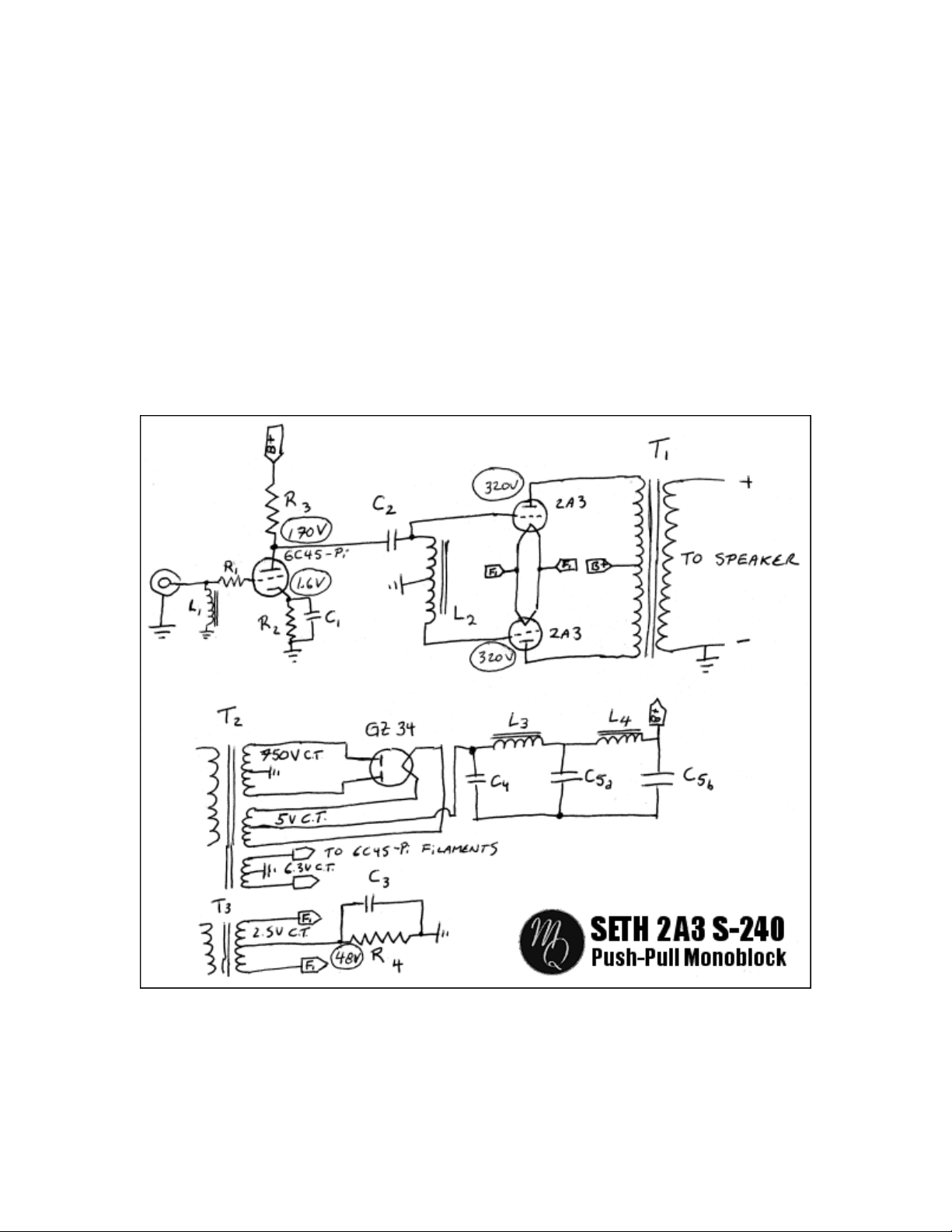
Schematic
The Seth has a very low part count. It is actually deceptively simple. It is in fact an out of
fashion design. No choke loading on the driver stage, no CCS, no bells and whistles.
Why? Simply for the newbie to build this amp easily. Does it sound good despite being
more or less fashionable? You bet.
Have a look at the schematic (note if you can’t read a schematic would it be to save your
life, I suggest you learn how to. Ain’t that complicated). The heart of this amp simplicity
is L
, the EXO-173 PPS center tapped choke. It acts as the phase splitter in a simple but
2
so elegant way. Putting the choke center tap to ground will create a reflected signal
inverted 180
connected).
o
on the bottom leg from the one that is fed on the top leg (where C2 is
The rest of the amp is as simple. It is a two stage design where a 6C45-Pi drives a pair of
2A3 in push pull class A. The PSU is a double pi filter, making for a very low ripple.
This amp is self biased. The pair of 2A3 shares a single bias resistor so this will ask for
closely matched tubes. The list of the parts I used in these amps is given below. Feel free
2

to experiment with the parts and please do not follow my choices blindly. After all, it’s
your amp your building, not mine.
R1
R2
R3
R4
C1
C2
C3
C4
C5a,b
T1
T2
T3
L1
L2
L3
L4
Two Dale metal film 100 ohms 1/4W in parallel
Holco metal film 43.5 ohms 1/2W
Mills Wirewound 4.02 K 12W
Mills Wirewound 12W 1 K in parallel with Mills Wirewound 12W 750 ohm
Black Gate "FK" 100 uF /16 V (optional I did remove it after listening with and without)
Solen 3.3 uF/630V
Black Gate "FK" 100 uF/100 V
Solen 1.5 uF/630V
Cerafine 47 uF+47 uF/500 V
MagneQuest "Peerless" S-240-A Ni
Hammond 374BX 375V-0-375 V 175 mA
Hammond 166Q2 2.5 V CT 6A
MagneQuest BCP16 GC Ni
MagneQuest EXO-173 PPS Ni
Hammond 193H 5 H 200 mA 65 ohms
Hammond 193H 5 H 200 mA 6 5ohms
3
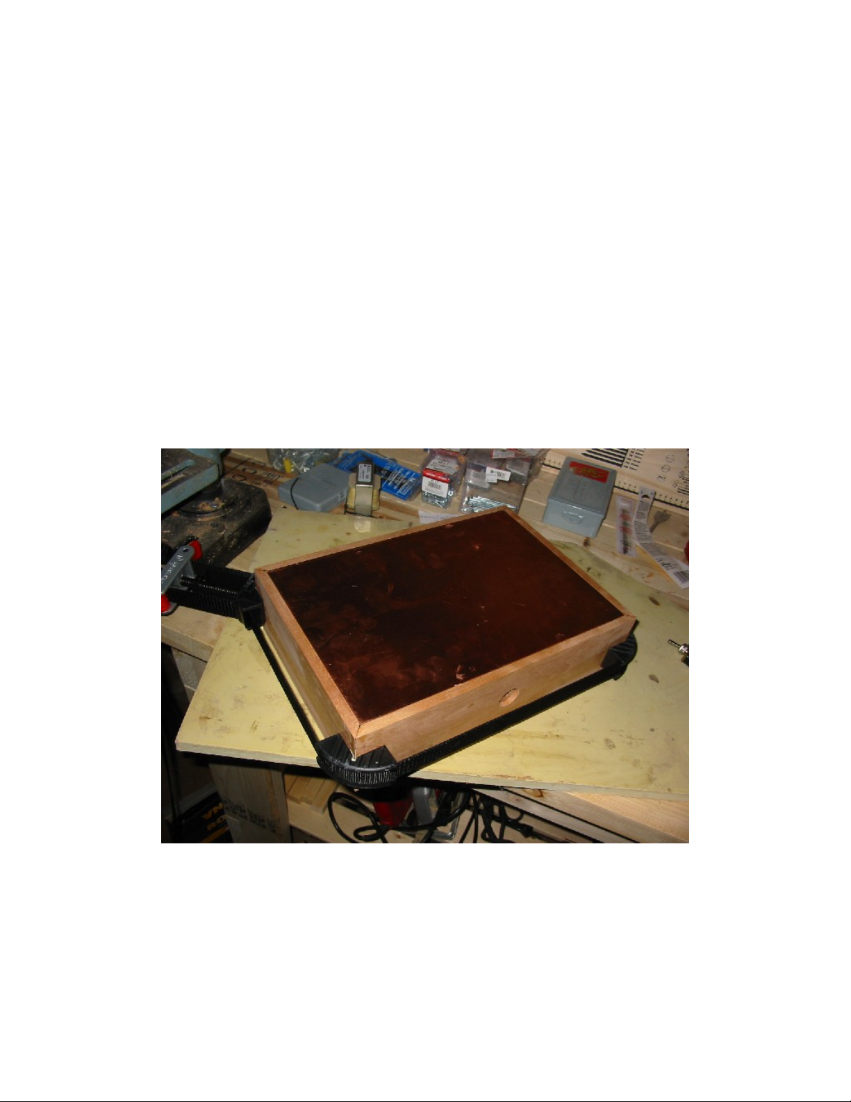
Building the wood chassis.
I always use wood chassis. I’ll be pretty vague here since you’ll find better advises that I
could give on the miscellaneous woodworking web sites so I’ll skip the details here. In a
nutshell I used a copper plate 18 AWG thick measuring 16” by 9” for the top plate.
Bottom plate is the same size but in aluminum (utility grade). I will usually oil the chassis
with either boiled linseed oil or Tung Oil for finishing the chassis.
I usually use a router to do a recess on the top and bottom of the chassis so the plates will
rest flush in them. I always use hard woods for my chassis so I can tap 6/32” threaded
holes into the wood in order to secure the plates with 6/32” machine screws. I always
work with 1” to 1”1/2 thick wood planks (once planed). I cut the wood with a mitre saw
according to my top plate size then I glue the four side with a special holding jig to
ensure square enclosure will be well … square!. You can find those jigs in most hardware
stores. Figure 1 illustrates a picture of a chassis drying while being clamped by the jig.
Once the chassis as set dry, I round the corners with a router despite a certain Kelly
Holsten always giving me shit about it.
Figure 1. Drying chassis (no it is not the chassis from the Seth…).
Figure 2 is a photo of the Seth chassis. Note the recess on the top of the chassis and the
tapped holes to secure the top plate. Figure 3 shows a detailed view of the “major holes”
to do in the chassis.
4

Once the chassis is done and finished, it’s time to install the components that will go on
the side of the chassis and start doing some of the AC wiring. Figures 4 to 8 will show
you how.
Figure 2. Completed chassis
Close up of the recessed
hole for the on-off switch,
fuse holder installation and
hole for the AC socket
Figure 3. Detail of the chassis holes.
5
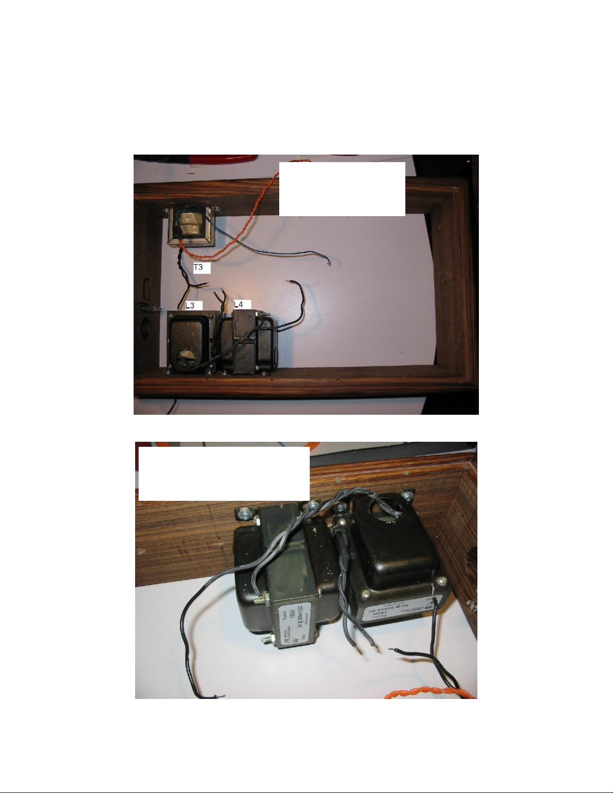
Figure 4 illustrate an overview of the parts location on the internal sides of the chassis.
Figures 5 and 6 shows close up of the PSU chokes and the two 2A3 filament transformer
installation. I used a “recycled” filament transformer (T
) so I had to make the leads
3
longer.
A top view of the location
of L3, L4 and T3 fixed on
the side of the chassis
Figure 4. Location of the chokes and the 2A3s filament transformer
Note that the laminations of L3 and
L4 are perpendicular to each other.
I fixed the chokes with wood
screws.
Figure 5 Close up of the PSU chokes (L3 and l4 on the schematic of the amp)
6
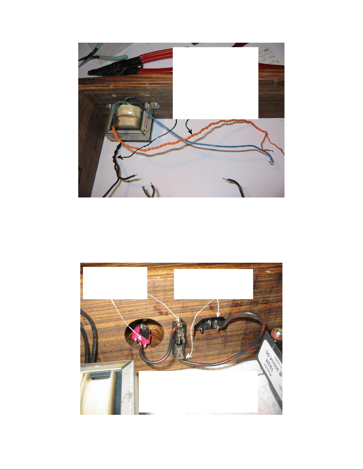
This is T3, the filament
transformer for the 2A3
filaments. It is fixed to the
chassis side with wood screws.
Since I recycled this transformer
from a previous project I had to
make the leads longer. You may
or may not have enough length
in your case. Just make sure to
twist the leads from the primary
and the secondary
Figure 6. Close up of the filament transformer (the blue wire is the secondary center tap)
Time to start wiring the AC now. It is important that you understand the method I
show here might be illegal in your area. This is your responsibility to make sure your
amp is safe and “legal” to use. Most electronic technician will be able to help you on this.
I am not. Figures 7 and 8 show the wiring of the fuse and the switch. I install them on the
“live” lug of the AC socket (often denoted by a “L” in the socket near the lug).
Solder a wire from the
on-off switch center pin
to one side of the fuse
holder.
Figure 7. First step of the AC wiring
Solder a piece of wire from
the other side of the fuse
holder to the live (hot) pin of
the AC socket.
IMPORTANT NOTE: THE WAY OF WIRING
THE AC SHOWN HERE MIGHT NOT BE
ACCORDING TO YOUR LEGISLATION,
CODES, ETC. IT IS YOUR RESPONSIBILITY
TO WIRE THE AC ACCORDING TO THE
RULES YOU ARE SUBMITTED TO.
7
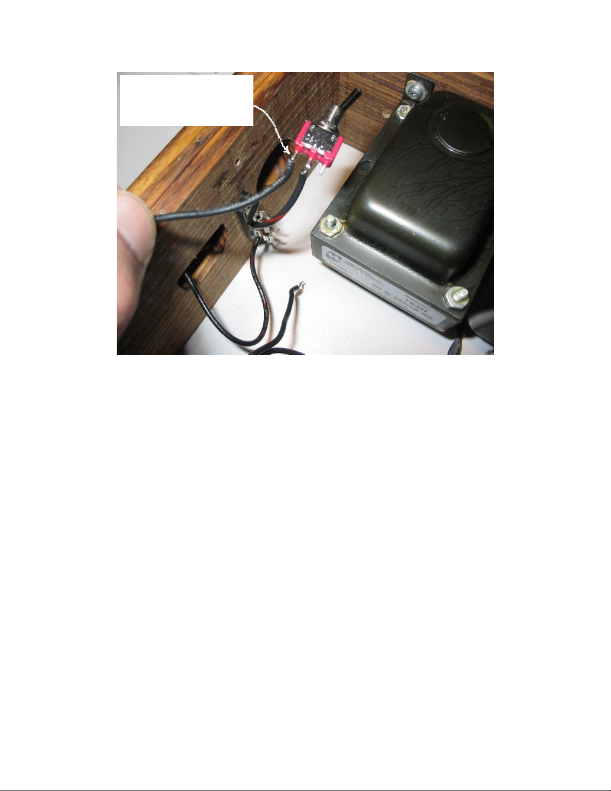
Solder a piece of wire to one
of the two outside pins of the
on-off switch. Leave the other
end of the wire loose for now.
Figure 8. Wiring the on-off switch.
Metal work.
Here is the part of the amp building process I don’t really enjoy. But that is just me…
About 90% of the amp building time is spent on the chassis (both wood and metal work).
I usually start by covering the top plate with masking tape and try out different layout that
will be both functional and aesthetic (at least to me…). Figure 9 illustrate this process.
Once the lay out is figured out I mark the location of the holes to be done and start the
punching process. Most holes are small holes for machine screws so they can be done
with a power drill. I personally use a small press drill. It goes like a charm. The larger
tube socket holes are done with Greenlee punches. I won’t recommend any dimension
here as it will be up to you to make sure you have the good punch dimension that will fit
your tube sockets size. For example, depending of the type of octal tube socket you will
get, you will need a 1” or a 1”1/8 punch.
Once all the holes are punched, I sand both side of the plate with an orbital sander. Figure
10 shows a finished and punched top plate waiting for the painting or coating or
whatever. I’ll be honest with you, I don’t paint those myself. I have a cat in the house and
no matter how careful I am, I always end up with a cat hair or two landing on the wet
paint. So I send them to the paint shop instead. Do I hear some of you say “Oh! What a
gorgeous copper plate! He should polish them and clear coat them!” Well be my guest
and go for it. Expect to spend a huge amount of time polishing these plates! Life is too
short in my case.
8
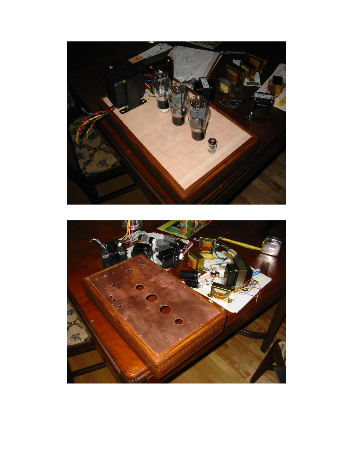
Figure 9. “Honey… What do you think of that one?”.
Figure 10. Once you are there you’ll have done 90% of the job.
9
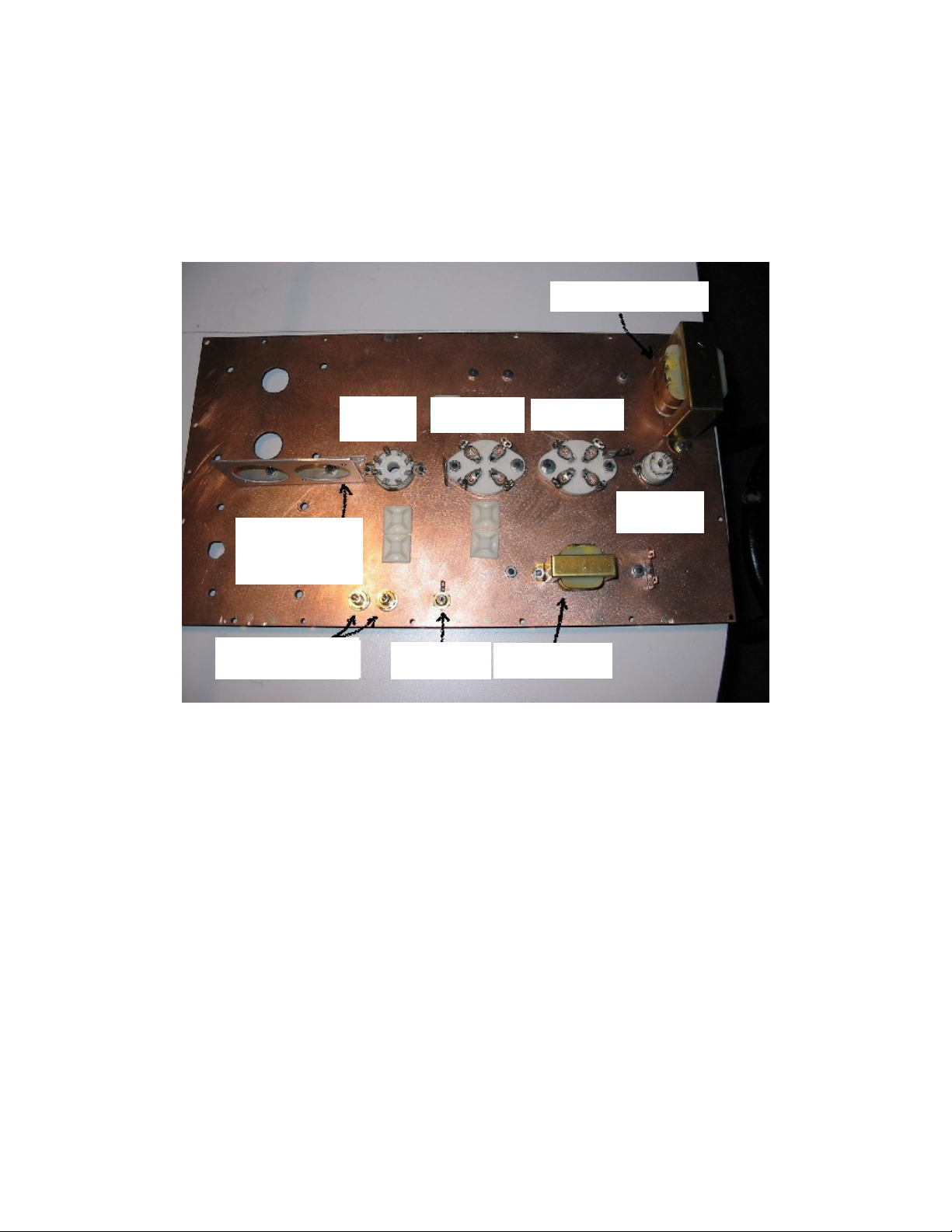
Figure 11 shows the mechanical mounting of the parts. The capacitor mounting bracket is
a nice gizmo I have made by batch of 20 by a machinist. But it is something you can do
yourself easily. This bracket will allow you to install the filtering cap (C5) in a
convenient way. Don’t bother with figuring out why the stick-on tying pads are already
on the copper plate. I cheated and dismantled a perfectly operating Seth to write this
“How-to” so they were already installed. See how I like you guys!
EXO-173 PPS Ni
Rectifier
socket
CAPACITOR
MOUNTING
BRACKET
BINDING POSTS
2A3 socket
RCA JACK
2A3 socket
6C45-Pi
socket
BCP16GC Ni
Figure 11. Internal mechanical mounting of the parts.
So… where will you punch your tube socket holes? Assuming you want a layout like
mine, all the tubes are straight on the centerline according to the long axis of the plate.
Assuming that the side of the plate on the rear of the amplifier is the reference point, the
rectifier tube is located at 6.25", the first 2A3 is at 9", the second 2A3 is at 11.5" and the
driver tube is at 14". I suggest you punch the other holes by locating all the transformers,
choke, binding posts, RCA jack in a similar fashion than I did. Mark the holes location
and punch them. Sorry not to be more precise but I was too lazy to make a plan.
You’ll need 3 solder lug strips for each monoblock for building this amp the way I did.
Two of these will be single lug strips and one will be a dual lug strip. Make sure the lugs
are not of the grounded type. Install them as shown in Figure 12. Done? How about a
beer now?
10

Solder lug strip
p
r
(2 lugs)
Solder lug strip
(1 lug)
Solder lug strip
(1 lug)
Figure 12 localisation of the solder lug strip.
IMPORTANT WARNING: IF YOU
ARE A US CITIZEN, DON’T
DRINK AND SOLDER AT THE
SAME TIME BECAUSE THE
GENERAL SURGEON WILL KICK
YOUR ASS. DRINKING MIGHT
IMPAIR YOUR SOLDERING
ABILITY.
The Belle Gueule Originale was
the official beer while building
this am
lifie
Figure 13. Time for a cold one.
11
 Loading...