

Page 1

MMC 2 INSTALLATION INSTRUCTION MANUAL
TABLE OF CONTENTS:
A. SELECTION OF SPEAKER LOCATION
B. PAINTING SPEAKER FRAMES
C. WALL PREPARATION
D. TOP FRAME INSTALLATION
E. ATTACHING BOTTOM FRAME TO SPEAKER
F. BOTTOM FRAME ATTACHMENT TO WALL
G. FINAL SPEAKER INSTALLATION
H. CAUTIONS
I. HOOKUP
J. SPEAKER ANGLE ADJUSTMENT
With a little experience, one person can install an MMC 2. However, for the first time, it is
recommended that an assistant help with steps D and E of the installation.
A. SELECTION OF SPEAKER LOCATION
Before a permanent installation is begun, we suggest that the Magneplanar Temporary Mounting Kit be used to
determine if the selected location gives the desired audio performance for the MMC 2s. A set of mounting
brackets are included with the MMC 2 for this purpose. Install the rubber washer on the bottom shaft to keep the
speaker in the desired position.
Because the MMC 2 can used for any channel in a home theater or music system and because rooms conditions
vary greatly, specific and detailed instructions are not practical. However, there are general guidelines to follow.
Avoid corners. Choose a placement that will position the MMC 2 as far from a corner as possible - preferably
more than 3 or 4 feet and the further, the better. We want you to be a satisfied customer and this is a critical
issue for good sound. This is especially important for the front channels. Rear channels play a lesser role and
more liberties can be taken with the rear channels.
Choose a placement that will allow the bottom of the MMC 2 to be approximately 26 inches from the floor for
proper high frequency dispersion when you are sitting or standing.
To help determine the front of the MMC 2, the quasi ribbon foil can be seen through the fabric on the front of the
speaker. The speakers should be mounted so that the front of the speakers are on axis with the listener.
CAUTION- Using a level, check to see if the walls are within building code for plumb (vertical to a level floor). If
the walls are too far out of plumb, the speakers may not open or close.
B. PAINTING SPEAKER FRAMES
Many customers will want to paint the top and bottom molding to match their decor. The top and bottom frames
can be ordered with a primer coat. We recommend Krylon spray can paint.
1. Mask off hardware in the speaker frames to prevent paint from fouling mechanical parts.
2. Spray 4 or 5 light coats, allowing drying time to prevent runs in the paint and for a smooth finish. Sand with
fine 600 sandpaper between coats for an extra-smooth finish.
3. Spray a coat of Krylon clear coat (gloss or satin) to protect the finish.
4. Install the speaker trim in the edge of the speaker with a rubber mallet. (Masking tape over the trim will
help prevent marring of the finish from the rubber mallet.)
5. Install 3/4 inch, 18 ga. brads in the speaker trim to secure the trim.
Page 2
5. Install 3/4 inch, 18 ga. brads in the speaker trim to secure the trim.
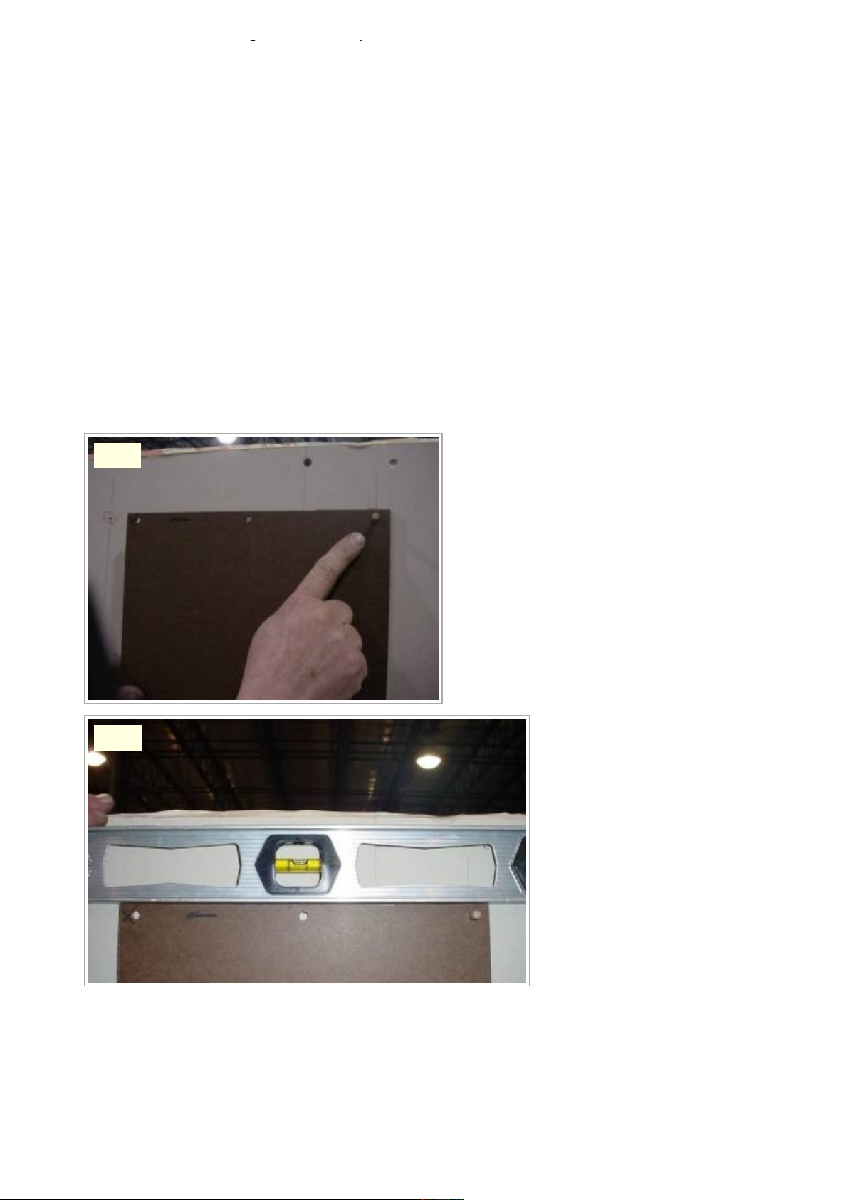
C. WALL PREPARATION
1. Position the hardboard template against the wall approx. 26" from the floor where the speaker is to be
located. Locate the speaker between studs whenever possible. Mark the wall using the upper right corner
hole of the template. Set the template aside.
2. Drill a 1/4" dia. hole in that location.
3. Hold the template against the wall and insert a 1/4" dia. dowel in the hole, leaving 1/4" exposed. See Fig.
1.
4. Level the template by placing a level on the top or side of the template. See Fig. 2. CAUTION- Take great
care to ensure that the wall is plumb (vertical) and the template is level before drilling the holes. The
speakers will not close or open if severely out of plum or level.
5. Drill a 1/4" dia. hole in the upper left corner of the template. Insert a 1/4" dia. dowel in this hole also. The
template will now hang unassisted.
6. Hold the template against the wall and drill the remaining 4 holes. Set the template aside.
7. Install (4) sheet rock anchors in the outermost (4) holes. Center holes are for wire feed only.
8. Install (4) #8 x 1-1/2" screws, keeping the screw head approx. 3/16" from the wall using the spacer
provided. USE HAND TOOLS ONLY. NO POWER TOOLS!
9. Install painter's tape on the wall above the location of the top frame to prevent marring of the wall while
installing the top frame.
Fig. 1
Fig. 2
Page 3
D. TOP FRAME INSTALLATION
1. Thread motor wires through the 1/4" dia. center hole and attach the top frame using keyholes on the back
of the top frame. If necessary, adjust the screw height to insure a snug fit of the top motor frame to the
wall. See Fig. 3 & 4.
Fig. 3
Fig. 4
Page 4

E. ATTACHING BOTTOM FRAME TO SPEAKER
1. Lay the speaker on a table with the bottom extending about 12" over the edge of the table.
2. Thread the speaker wires through the bottom frame and insert the bottom pin of the speaker into the pivot
hole of the bottom frame. See Fig. 5 & 6.
Fig. 5
Fig. 6
Page 5

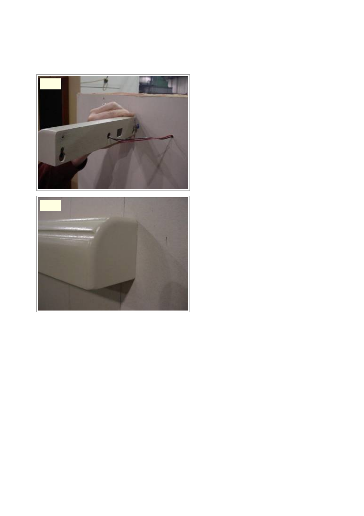
F. BOTTOM FRAME ATTACHMENT TO WALL
1. While keeping the bottom frame and speaker together, take the speaker to the wall for installation. See
Fig. 7.
2. Feed the speaker wire through the 1/4" dia. bottom center hole and attach the lower frame to the wall using
the keyholes on the back of the bottom frame. See Fig. 8 & 9.
Fig. 7 Fig. 8
Fig. 9
Page 6

G. FINAL SPEAKER INSTALLATION
This final step is the most difficult (and may require the help of an assistant). Slightly raise the top frame to allow
clearance for the pin on the top of the speaker wheel to clear the top frame when it will be moved into position.
See Fig. 10. Slide the motor assembly (and drive wheel) back with your thumb (See Fig. 10) to allow clearance
between the two wheels so that the pin on top of the speaker wheel can be inserted into the top frame pivot hole.
See Fig. 10.
H. CAUTIONS
1. The top frame must be snug to the wall to prevent accidental dislodging of the top frame. Readjust the top
screw heights, if necessary, for a snug fit into the key holes.
2. Important- The wheels must be properly aligned for FULL contact to ensure that the wheels will not slip
during opening or closing. Adjust the wheel height on the speaker with the included allen wrench, if
necessary. The help of an assistant will be required to adjust the wheel height. Raise the top frame and
with the help of an assistant, hold the speaker in position while loosening the two wheel set screws and
adjusting the height of the wheel on the speaker shaft.
I. HOOKUP
Connect the positive (red) speaker wire to the MMC 2 white and red wire. We recommend that the connection to
the speaker wire be soldered with shrink tubing for electrical insulation. Check for correct phasing before making
a permanent connection.
Fig. 10
Page 7

J. SPEAKER ANGLE ADJUSTMENT
1. For the best sound, the MMC 2 should be angled so that the panel is on-axis with the listener with a
minimum distance from the wall of 30 degrees. (Use of the MMC 2 as a dual center channel speaker
requires slightly different adjustments. Contact Magnepan for specific instructions). Pull the MMC 2 out
until you feel the resistance of the Cam/Stop. Insert a long 5/64 inch allen wrench into the Cam/Stop at the
bottom of the speaker as shown in Figs. 11 and 12 and loosen the allen screw.
2. Rotate the MMC 2 to the desired position and tighten the allen screw. See Fig. 13 and 14.
3. The angle of the MMC 2 should never be set for less than 30 degrees for optimum sound.
The MMC 2 can be pushed past the stop position without causing harm to the speaker or motor system. The
MMC 2 will usually automatically reset back to normal operation after cycling the motor once or twice or if the
speaker is pushed beyond the stop position, the panel can be manually pushed back into position.
A nylon screw is included with the MMC 2 to act as a stop so that the MMC 2 can be adjusted to be parallel with
the wall in the closed position. The screw hole is located at the bottom inside edge of the MMC 2. To ensure that
the nylon screw will not loosen, wrap Teflon plumber's tape on the threads or a drop of blue Loctite or score the
threads lengthwise.
Fig. 11
Fig. 12
Page 8

Fig. 13
Fig. 14
 Loading...