

Page 1

MAGNEPLANAR® MG3.6/R
Instruction Manual
MAGNEPLANAR® PRODUCTS
WHITE BEAR LAKE, MINNESOTA 55110
www.magnepan.com
Page 2

1. INTRODUCTION
Congratulations on your purchase. The Magneplanar MG3.6/R loudspeaker was
conceived and designed for perfectionists. One of the most revealing loudspeakers
made, it will provide outstanding music reproduction when used with high quality
components. Due to the elegant simplicity and ruggedness of the design, the
Magneplanar MG3.6/R loudspeaker will give many years of trouble-free service.
2. GENERAL DESCRIPTION
The MG3.6/R speaker system consists of a pair of mirror-imaged panels, labeled "1"
and "2" (for identification). Each panel contains one, five-foot long ribbon tweeter and
one mid/bass planar-magnetic driver. The planar-magnetic driver consists of a bass
section and a midrange section on a common ½ mil. Mylar diaphragm.
The crossover components for the bass and midrange are housed in a pair of external
crossover boxes. The midrange to treble crossover components are housed in the
speaker panel and are non-defeatable.
Although the MG3.6/R system is set up for conventional single amplifier operation, the
speaker input plates provide for bi-wiring or bi-amplification as an option.
3. ACCESSORY CARTON CONTENTS
4 - Speaker Support Feet
8 - Speaker Support Bolts
2 - 2-1/2 Amp Normal Blow Fuses, Type SAG (Tweeter)
2 - 4 Amp Normal Blow Fuses, Type SAG (Midrange)
2 - External Crossover Boxes
1 - Direct-Connect Crossover Installation Bracket Set
1 - Hex Wrench
2 - Speaker Emblems
2 - 1 Ohm Resistors
1 - Owner's Manual
4. IMPORTANT PRECAUTIONS
FRAGILE! The foil element in the ribbon tweeter is quite fragile. Handle the speaker
panel with care. Do not drop flat on the floor. Air pressure can rupture the element.
RUPTURED RIBBON ELEMENTS ARE NOT COVERED UNDER THE WARRANTY!
Page 3
5. PACKAGING
Save all packaging, including the protective cover for the ribbon tweeters. If you need
to transport the speakers, they can be shipped safely only in the original packaging.
You may never have to return your speakers, but should the occasion arise, they
should not be shipped in any packaging but the original. Should you discard it, factory
packaging is available, including special packaging for ribbon tweeters.
6. SPEAKER UNPACKING AND ASSEMBLY
UNPACKING SPEAKER-DO not pull a speaker abruptly from the carton. The resulting
partial vacuum could burst the ribbon. Do not remove the tweeter protector strips until
the speaker is completely assembled.
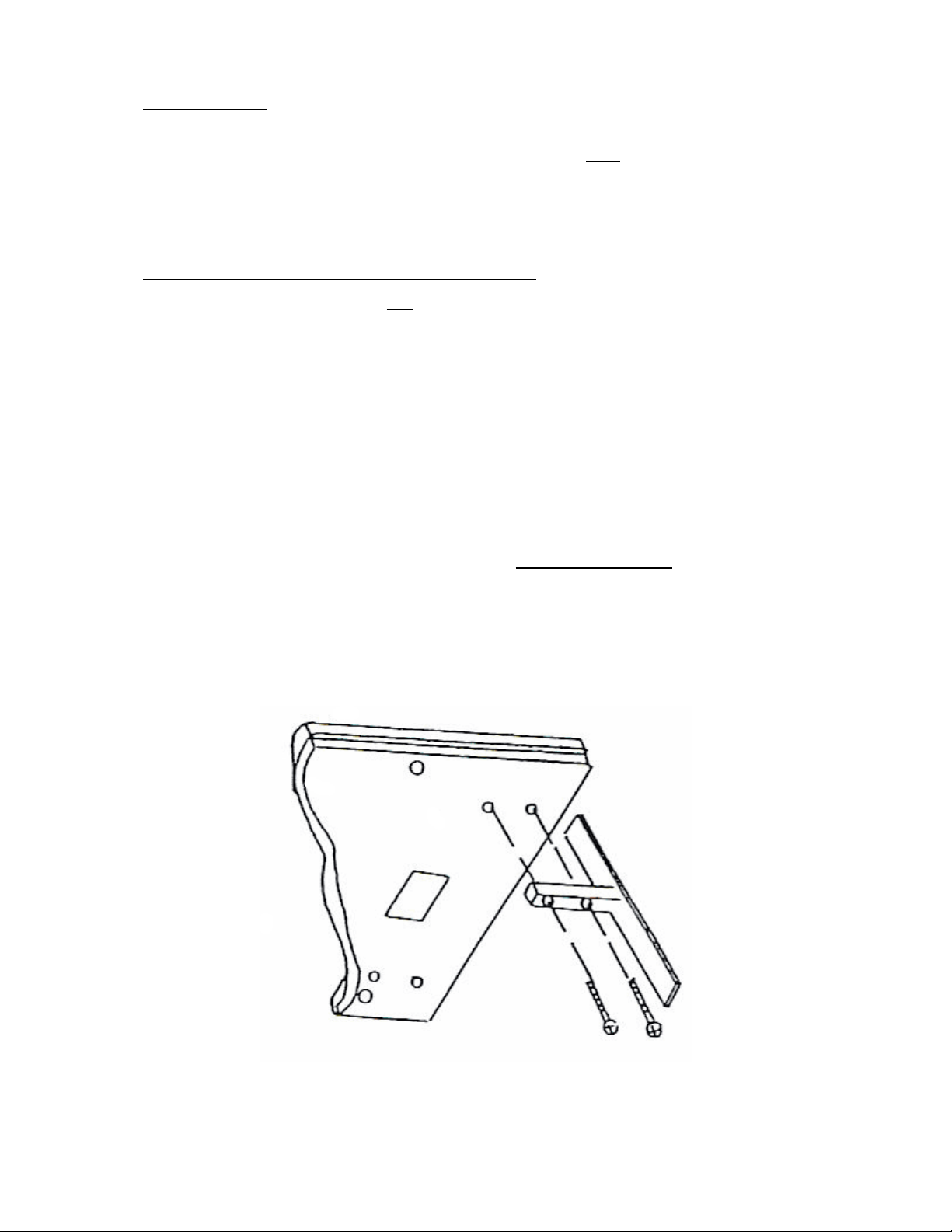
SUPPORT FEET INSTALLATION-The four support feet are shipped in the separate
accessory carton along with the eight mounting bolts. Two feet must be fastened to the
backside of each of the panels. The nuts are already installed in the panels.
A. Lay the speakers on the side as shown in Figure 1. We suggest you have a
second person hold the speakers during installation to ensure they do not fall.
B. Locate the four holes in the fabric along lower backside of the panel.
C. Carefully place a foot from the backside against the panel so the holes in the
foot align with the holes in the panel. Using your fingers, insert bolts through
the foot and into the panel until they engage nuts in the panel. Care should be
taken so the bolts do not cross-thread. Final tightening is done with a Phillips #2
screwdriver. Repeat for remaining foot.
Figure 1
Page 4

7. HOOKUP
This section covers amplification with a single stereo amplifier. For instruction on biamplification or bi-wiring, refer to Sections 11 and 12.
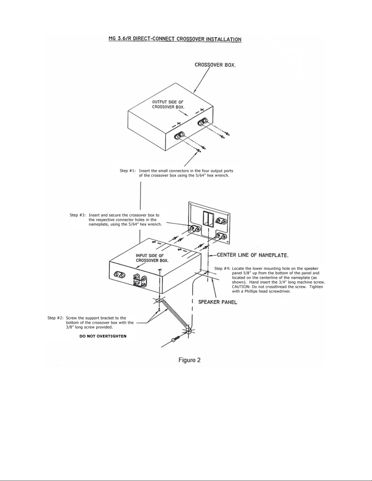
DIRECT-CONNECT CROSSOVER INSTALLATION
A. Insert the small connectors in the four output ports of the crossover box, using a
5/64" hex wrench. See Figure 2, Page 4.
B. Screw the support bracket to the bottom of the crossover box with the 3/8" long
screw provided. DO NOT OVER TIGHTEN!
C. Insert and secure the crossover box to the respective connector holes in the
nameplate, using a 5/64" hex wrench.
D. Locate the lower mounting hole on the speaker panel 5/8" up from the bottom of
the panel, and located on the center line of the nameplate (as shown). Handinsert the 3/4" long machine screw. CAUTION: Do not cross thread the screw.
Tighten with a Phillips head screwdriver.
The MG3.6/R features high-current cable connectors which provide optimum contact
area with speaker cables up to 10 gauge. To prepare cables, strip 1/2" of insulation
from the end of the cable. Insert the bare wire into the connector and tighten the setscrew with the Alien wrench provided. Take special precautions to ensure correct
polarity on all speaker cable connections. Most speaker cables have some sort of
coding on one lead, either printing, colors, or a "rib" to help in maintaining polarity.
Spade lug adapters are available from your Magneplanar dealer for speaker cables
that are incompatible with the Magneplanar high-current connector.
Page 5
Page 6

FUSING – The mid and treble sections of the MG3.6/R are protected with Type SAG
normal blow fuses (4 amp for midrange; 2-1/2 amp for tweeter). The bass section does
not require fusing protection. The fuse values should never be increased or bypassed.
Do not use slow-blow fuses. Fuses remain in effect when bi-amplifying. This is done for
your protection since it prevents overdriving from an amplifier, or the distortion that
results from an overdriven amplifier (clipping).
In case the MG3.6's do not sound "quite right," especially after high volume levels,
please check the midrange fuse. When it is blown some owners do not realize it, since
a blown midrange fuse is not as apparent as a blown tweeter fuse. Some amplifiers will
distort or go into thermal overload when driving MG3.6's with a blown midrange fuse.
BURNED OUT MID OR TREBLE SECTIONS ARE NOT COVERED
UNDER THE WARRANTY.
8. SPEAKER PLACEMENT
Proper speaker placement and room acoustics can have more effect on a music
system than upgrading one of the components in the system. Unfortunately, there is no
definitive guideline which will cover all possible listening rooms. Considerable
experimentation is required for locating the optimum position. The following are a few
general guidelines:
TWEETER PLACEMENT
The MG3.6 tweeters are mirror-imaged. For proper phasing between the bass,
midrange, and tweeter, the bass driver should be closer to the listener than the
tweeter (ahead in time). If the tweeters are placed on the outside, the angle of
the speaker in relation to the listener should be as shown in Figure 3. If the
tweeters are placed on the inside, the speaker angle should be as shown in
Figure 4.
BASS RESPONSE
If you do not have access to a spectrum analyzer, play a record with a repetitive
bass line (preferably an acoustical bass instrument). Try the speakers in several
parts of the room. Start experimenting with the speakers about 3 feet from the
back wall. Try moving the speakers forward or backward by increments of 6 to
12 inches at a time. One part of the room should be noticeably better than the
rest, as should one distance from the rear wall as shown in Figure 5.
Page 7

Page 8

Figure 5
STEREO WIDTH AND IMAGING
Once you have located the best position for the speakers and your chair for
good bass performance, separate the tweeters by 50% of the distance from your
chair to the speakers. (For example, if your chair is 10 feet from the speakers,
move the tweeters 5 feet apart.) Now move the speaker apart in increments of 3
or 4 inches at a time, listening carefully at each position. At some point you will
start to hear two separate speakers instead of getting a "stage effect" (or
continuous image). If you have a hole-in-the-middle effect, your speakers are
too far apart: begin moving the speakers closer together in small increments
until you notice a point at which you achieve one cohesive "sound stage." See
Figure 3 or 4.
A small tack or piece of tape can be attached to the carpet so the ideal spot can
be easily relocated when the speakers (or chair) are moved for cleaning, etc..
The entire placement procedure may seem like a great deal of work, but is
necessary in the setup of any high quality system. The time and effort
expended should be necessary only once, but will repay the owner with
countless hours of musical enjoyment.
Page 9

9. ROOM ACOUSTICS
Magneplanars, like other bipolar speakers, usually sound best with a moderately
reflective surface behind the speakers. In situations where the speakers must be
placed closer than 2 feet from the back wall, a heavy damping material directly behind
the speakers is advised; however, it should not cover the entire wall.
Damping material in other parts of the room is a matter of trial and error. A word of
caution-when audiophiles discover the effectiveness of damping material, they
sometimes overdo it (on the premise that if a little is good, more is better). Before you
make a permanent change to your room, experiment with the positioning of the
damping material. Usually a portion of one or two parallel walls should have some
damping.
An overdamped room will provide very precise imaging, but you will have a reduced
sense of ambience (less reverberation, spaciousness). An underdamped room may
heighten the illusion of being in a concert hall, but the imaging will seem imprecise with
all the instruments mixed together. Moderation is the word.
10. OPTIONAL RIBBON TWEETER ATTENUATION
There are two principal reasons for needing to attenuate the Magneplanar Ribbon
Tweeter:
A. Recordings, typically in the "pop" or "rock" vein, often exhibit a pronounced rise
in the treble region.
B. The Magneplanar Ribbon Tweeter is very efficient in its total "energy
dispersion." If the surrounding walls are exceptionally reflective, the overall
perceived acoustical balance will be tipped towards a "hot" high end.
Attenuation is performed through insertion of a simple non-inductive resistor in series
with the tweeter.
There are inputs provided on the connector plate of each speaker for insertion of a
resistor. To insert a resistor, simply loosen the Alien screws, remove the jumper, insert
the resistor, and tighten the screws.
The pair of 1 ohm non-inductive resistors provided will attenuate the tweeter
approximately 1-2dB. Other values are available from your Magneplanar dealer.
Page 10

11. BI-AMPLIFICATION WITH CONVENTIONAL ELECTRONIC CROSSOVER
The MG3.6/R is arranged conveniently for bi-amplification. By adding an additional
stereo amplifier and a crossover, you can enjoy the benefits of increased dynamic
range and lower distortion.
1. Set your electronic crossover at the following points and slopes:
Low Pass: 18dB per octave at 250Hz
High Pass: 6dB per octave at 200Hz
2. Connect the bass and mid/treble amplifiers directly to the speakers as
shown in Figure 6. Do not use the MG3.6 external crossover box.
Figure 6
3. Since the effective crossover point for the MG3.6/R is approximately
250Hz, the power requirements for the bass midrange/treble amps are
nearly the same. Therefore, use amplifiers of similar power rating. It is
suggested to use amplifiers rated at 100 watts RMS or greater, into 8
ohms.
Page 11

12. BI-WIRING OPTION
Bi-wiring requires two sets of speaker cables. They may be identical or one set may be
specialized for high frequencies and the other specialized for low frequencies.
A. Remove both jumpers on the crossover box.
B. Connect one set of cables to the low cable input and the other set to the high
cable input. Connect the other end of the cables together (observe +/- polarity),
and connect to one channel of the amplifier outputs. If frequency specialized
cables are used, connect them to their respective inputs. In either case, the
other ends are connected to the same amplifier channel.
C. Repeat same procedure for the other channel.
13. MAINTENANCE
The wood trim can be cleaned and polished with a damp cloth. In the event the speaker's
fabric is damaged or soiled, replacement covers are available. For owners with cats, we
recommend cat repellant around the base of the speakers. Do not use a vacuum cleaner!
14. SERVICE
In the unlikely event you should need service for your MG3.6/R loudspeakers, we
recommend you return them to your dealer. He is experienced in providing service and
can assist you if the speakers must be returned to the factory.
If it is determined that your speakers must be returned for repair, you must call the
factory first for a return authorization repair number. Ship your speakers (freight
prepaid-ask for Class 100) to:
Magnepan, Incorporated
1645 Ninth St.
White Bear Lake, MN 55110
651-426-1645 or 800-474-1646
Include a packing slip or letter describing the nature of the problem and your return
authorization repair number. Please include your name, address, and a daytime
telephone number.
Before packaging, very carefully install the steel protector strips over the ribbons. Do
not let the steel strips slap against the magnets.
THE RIBBON ELEMENT WILL BE RUPTURED IF SHIPPED WITHOUT THE STEEL
PROTECTOR STRIPS AND WOULD NOT BE COVERED UNDER THE WARRANTY.
Page 12

15. THE RIBBON TWEETER
Because the foil element in your MG3.6/R line source tweeter is only .00015 inches
thick, it is very fragile. It's the price we pay for ultra-high performance. Most users will
never require a replacement tweeter. Failure will generally occur from mishandling, or
from very high impulse signals from a few unusual compact discs used with very high
powered amplifiers. Users that frequently push the 2.5 amp tweeter fuse capacity will
be the most likely to experience early failure. Because of this, the tweeter has been
designed to be easily replaced, requiring only a screwdriver. The time required should
be less than 30 minutes.
If you have a defective tweeter, you should contact your dealer for a replacement.
Ribbon tweeters for previous MGIII models cannot be used in your MG3.6/R's. Your
defective unit will be returned to Magnepan for installation of a new foil element at a
minimal charge to you: there is no charge if it is within the one-year warranty period
that covers the foil element and Magnepan determines that there is no evidence of
abuse. DO NOT SHIP A TWEETER BACK TO MAGNEPAN WITHOUT CONTACTING
YOUR DEALER OR MAGNEPAN FIRST. Tweeters must be returned in authorized
containers only. Tweeters that are damaged in shipment are the responsibility of the
customer.
Page 13

16. 60" VERSION 2 RIBBON TWEETER REPLACEMENT
Tools Needed: #2 Phillips Screwdriver
1. Place protective cover over backside of
ribbon tweeter, as shown (to prevent
damage to ribbon while moving the
speaker panel).
2. Carefully lay speaker on a flat table or
working surface.
3. Remove the protective cover and pry
away the two end covers.
4. Pull off the connector at each end of
the ribbon tweeter with a pair of needle
nose pliers.
5. Reinstall protective cover over ribbon.
6. Remove the screws that attach the
ribbon tweeter to the frame and then
remove the tweeter.
Needle Nose Pliers
7. Install the new ribbon tweeter in the
frame. Serial number label must be at
the bottom.
8. Insert the screws. (Tighten until snug,
then back off ½ revolution.)
9. Remove protective cover and reattach
connectors to the ribbon lugs.
10. Peel liner from back of end covers and
adhere to each end of tweeter.
11. Install protective cover.
12. Reposition speakers in listening
position and remove protective cover.
13. Pack old tweeter(s) in the tube and
packing provided and return to your
dealer or Magnepan.
CAUTION: Do not bump of touch the ribbon at its end terminals. Also do not tug on the fine
wire jumper that is soldered to the foil and attached to the end terminal. All ribbon tweeters
returned to the factory MUST be returned in the factory packing.
Page 14

17. MG3.6/R SPECIFICATIONS
SYSTEM DESCRIPTION: 3-Way True Ribbon Tweeter, Planar-Magnetic Midrange and
Bass with Bi-Amplification Option
BASS SECTION: 500 Sq. In. Planar-Magnetic
MIDRANGE SECTION: 199 Sq. In. Planar-Magnetic
TWEETER SECTION: 5/32 Inch Width, 55 Inches Long FREQUENCY RESPONSE:
**34Hz to 40kHz ±3dB
POLAR RESPONSE - RIBBON DRIVER: 180° Horizontal dispersion both front and
back to 20kHz
RECOMMENDED POWER: 75 to 250 Watts RMS (8 Ohm rated). SENSITIVITY:
86dB, 500Hz, 2.83Volts
IMPEDANCE: Bass- 4.7 Ohms
Midrange/Ribbon Tweeter- 4.2 Ohms Ribbon Tweeter- 3.3 Ohms
CROSSOVER: Crossover between bass and midrange is 200Hz
Crossover between midrange and tweeter is 1700Hz
DIMENSIONS: 24'W X 71"H X 1-5/8"D
WARRANTY: Limited. Non-transferrable - Ribbon Foil Element - 1 Year
Balance of Speaker - 3 Years
SHIPPING WEIGHT: 145 Lbs. With Accessory Package
*Because there are no universally accepted methods for loudspeaker measurement,
frequency response specifications may be stated by most manufacturers without
reference to measurement techniques and/or specific locations in rooms. Magneplanar
loudspeaker frequency response curves are minimum average performance levels that
may reasonably be expected in normal installations.
**New Magneplanar MG3.6/R speakers will not display their full bass potential. After a
month or two of use the bass response will lower 5Hz or more. At this point the
response will stabilize and the speakers rated performance (or better) can be realized.
While this 5Hz or more of lower bass response is important, the most important factors
in obtaining good bass response from the MG3.6/R speakers are room size and
geometry, wall material, and speaker placement.
 Loading...