

Page 1

MAGNEPLANAR MG1.6/QR
Instruction Manual
MAGNEPLANAR® PRODUCTS
WHITE BEAR LAKE, MINNESOTA 55110
www.magnepan.com
Page 2

1. INTRODUCTION
Congratulations on your purchase. The Magneplanar MG1.6/QR loudspeaker was conceived
and designed for perfectionists. One of the most revealing loudspeakers made, it will provide
outstanding music reproduction when used with high quality components. Due to the elegant
simplicity and ruggedness of the design, the Magneplanar MG1.6/QR loudspeaker will give
many years of trouble-free service.
2. GENERAL DESCRIPTION
The MG1.6/QR consists of a 2-way planar magnetic driver utilizing a common 1/2 mil. Mylar
diaphragm. The voice grid of the bass section consists of a lightweight aluminum wire. The
Quasi Ribbon Tweeter is made of 1 mil. aluminum foil.
3. PACKAGING
Save all packaging. If you need to transport the speakers, they can be shipped safely only in
the original packaging. You may never have to return your loudspeakers, but should the
occasion arise, they should not be shipped in any packaging but the original. Should you
discard it, packaging is available.
4. ASSEMBLY
The four support feet for the MG1.6 are shipped in the speaker carton along with the 8
mounting bolts. The nuts for the mounting bolts are already installed in the panel.
The spacers and 4 longer bolts are provided to adjust the vertical angle of the speaker. The
amount of angle will be dependent on your particular listening conditions. Under most
conditions, stacking 2 spacers will be adequate; however, some experimentation may be
necessary.
A. Remove speakers and feet from carton. The 8 mounting bolts are installed in the
speakers.
B. We suggest the assistance of a second person will facilitate the installation of
the feet. Hold a speaker upright on it's side.
C. Remove the 8 bolts from the nuts. Carefully align foot on backside of panel so
holes in the foot line up with the bolts in the panel. Using your fingers, insert a
bolt through the center hole (see Figure 1 if using spacers and long bolts),) until
the bolt engages with the nut in the panel. Care must be taken not to crossthread the bolts.
E. Repeat the same procedure for top hole, eliminating the spacers.
F. Tighten all bolts securely.
Page 3
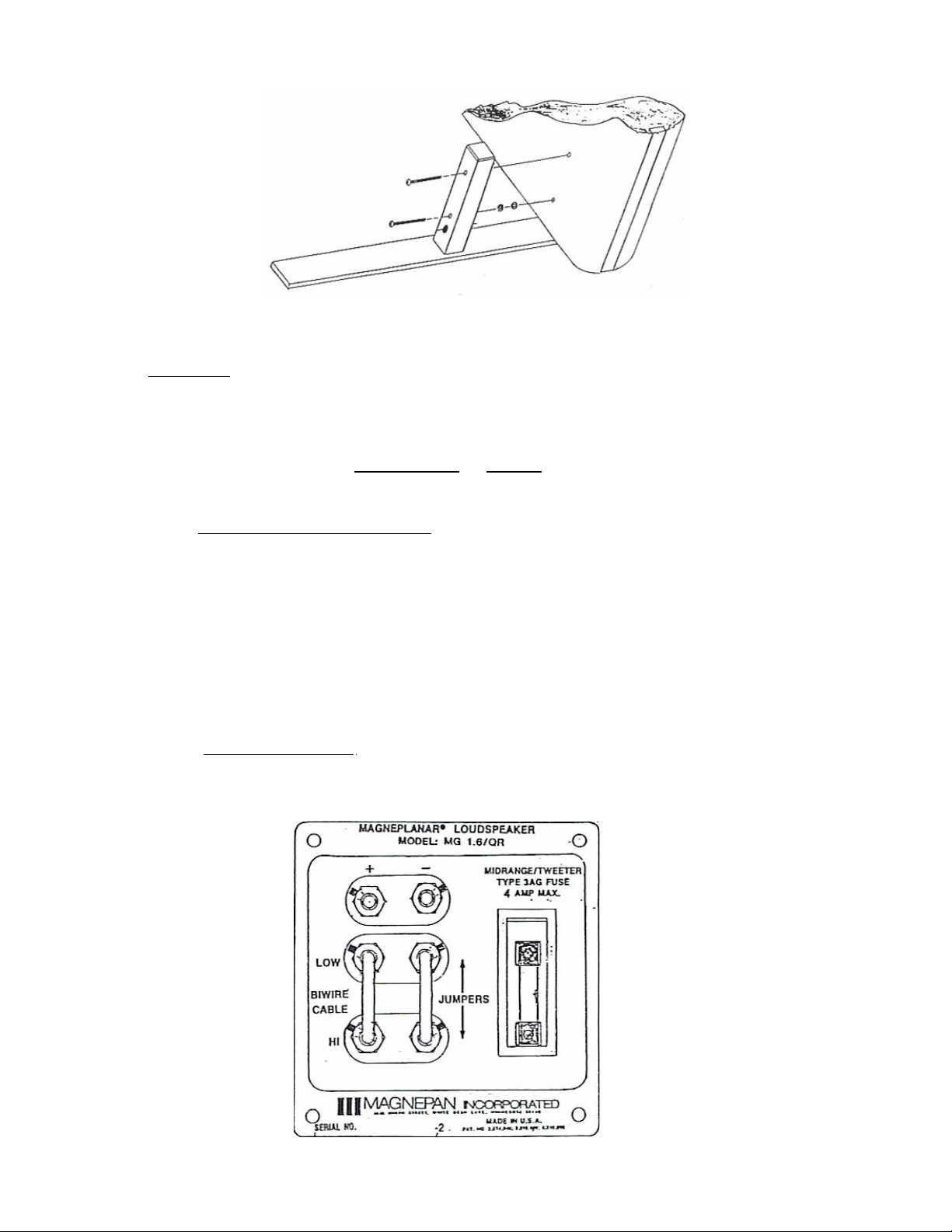
Figure 1
5. HOOKUP
The MG1.6 features unique, high current connectors which provide optimum contact area with
speaker cables up to 10 gauge.
The MG1.6 is shipped ready for conventional or bi-wire hookup.
A. CONVENTIONAL HOOKUP
Simply strip 1/2" of insulation from the end of the cable. Insert the cable into the
top set of connectors and tighten the set screws with the Alien wrench provided.
Banana plug connectors can be used and locked in place with the set screws.
Spade lug adapters are available from your Magneplanar dealer for speaker
cables that are incompatible with the Magneplanar high current connector.
To ensure proper phasing of the speakers, make sure the plus (red) is to plus
and minus (black) is to minus.
B. BI-WIRE HOOKUP
These speakers are designed for utilizing bi-wire hookup techniques. The
connection plate on the rear of each speaker is shown in Figure 2.
Page 4

a. Remove both jumpers.
b. Connect one set of cables to the low-cable input and the other set to the
hi-cable input. Connect the other end of the cables together (observe +/polarity), and connect to one channel of the amplifier outputs. If frequency
specialized cables are used, connect them to their respective inputs. In
either case the other ends are connected to the same amplifier channel.
c. Repeat same procedure for the other channel.
6. CAUTION-CAUTION-CAUTION
A. The terminal plate states a maximum fuse value of 4 amps Type SAG ("normal"
or "fast blow"). We recommend that 4 amp fuses continue to be used. The bass
section does not require fusing protection. This fuse value should never be
increased or bypassed. Do not use slow-blow fuses. If these precautions are
taken, our destruct tests show that it is impossible to burn out these drivers.
BURNED OUT TWEETERS ARE NOT COVERED UNDER THE WARRANTY.
B. For owners of cats, we recommend cat repellant around the base of the
speakers.
7. SPEAKER PLACEMENT
Proper speaker placement and room acoustics can have more effect on a music system than
upgrading one of the components in the system. Unfortunately, there is no definitive
guideline which will cover all possible listening rooms. Some experimentation is required for
locating the optimum position. The following are a few general guidelines:
A. BASS RESPONSE
Play a record (or test signal) with repetitive bass. Try the speakers in several
possible locations in the room. Begin experimenting with the speakers about 3
feet from a back wall. Try moving the speakers forward or backward in
increments of 6 to 12 inches. One position in the room should be noticeably
better than others. Also experiment with your chair location. Positions close to a
wall will often result in increased bass (often too much). See Figure 3.
B. STEREO WIDTH AND IMAGING
Once you have located the best position for the speakers and your chair for
bass performance, separate the speakers by 50% of the distance from your
chair to the speakers. (For example, if your chair is 10 feet from the speakers,
move the speakers 5 feet apart.) Now, move the speakers apart in increments
of 3 or 4 inches at a time, listening carefully at each position. At some point you
will start to hear two separate speakers instead of a "stage effect" (or continuous
Page 5

image). When this occurs, your speakers are too far apart: begin moving the
speakers back in small increments until you notice a point at which you achieve
one cohesive "sound stage." For best results listen to speakers on axis with the
listening position as shown in Figure 3 and 4.
C. LEFT/RIGHT
The MG1.6's are matched pairs and mirror-imaged. The serial number for each
speaker in the pair is the same, except for a "1" or "2" following each serial
number. As you face the front of the speakers, the speaker with the "1" after its
serial number has the tweeter near the left edge, and the speaker with the "2"
has the tweeter near the right edge.
To obtain correct phasing between the tweeter and bass of the MG1.6, the
tweeters should be placed on the outside.
Page 6

Figure 3
Figure 4
Page 7

NOTE: Once you have located the ideal speaker position you should mark it. A small tack or
piece of tape can be placed on the carpet so that your ideal listening spot can be easily
relocated when the speakers (or chair) are moved for cleaning, etc. In the event that your
ideal listening spot is inconvenient from the standpoint of the room layout and decor, simply
slide the speakers wherever they look best. Experience has shown that the speakers can be
placed close to a wall, and it will make little difference for FM or background listening.
The entire placement procedure may seem like a great deal of work, but is necessary in the
setup of any high quality system. The time and effort expended should be necessary only
once, and will repay the owner with countless hours of musical enjoyment.
8. ROOM ACOUSTICS
Magneplanars, like other bipolar speakers, usually sound best with a moderately reflective
surface behind the speakers. In situations where the speakers must be placed as close as 2
feet from the back wall, a heavy damping material directly behind the speakers is advised;
however, it should not cover the entire wall.
Damping material in other parts of the room is a matter of trial and error. A word of cautionwhen audiophiles discover the effectiveness of damping material, they sometimes overdo it
(on the premise that if a little is good, more is better). Before you make a permanent change
to your room, experiment with the positioning of the damping material. Usually a portion of
one of two parallel walls should have some damping.
An overdamped room will provide very precise imaging, but you will have a reduced sense of
ambience (less reverberation, spaciousness, air, etc.). An underdamped room may heighten
the illusion of being in a concert hall, but the imaging will seem imprecise with all the
instruments mixed together. Be aware that so-called hardness or overbright sound is usually
the result of a room with hard surfaces (glass, hard paneling, etc.). Moderation is the word.
9. OPTIONAL TWEETER ATTENUATION
There are two principal reasons for needing to attenuate the Magneplanar Quasi Ribbon
Tweeter:
A. Recordings, typically in the "pop" or "rock" vein, often exhibit pronounced rise in
the treble region.
B. The Magneplanar Quasi Ribbon Tweeter is very efficient in its total "energy dispersion." If
the surrounding walls are exceptionally reflective, the overall perceived
acoustical balance will be tipped towards a "hot" high end. Attenuation is
performed through insertion of a simple non-inductive resistor in series with the
tweeter. See Figure 5. Replace the left-hand jumper with the appropriate
resistor to obtain the desired tweeter attenuation. The pair of 1 ohm noninductive resistors will attenuate the tweeter 1-2dB. Other values are available
from your Magneplanar dealer.
Page 8

10. MAINTENANCE
A. The hardwood trim can be cleaned with a slightly damp dust cloth.
B. Light vacuuming of the grille cloth is possible.
11. SPECIFICATIONS*
SYSTEM DESCRIPTION: Two-way full range planar-magnetic dipole radiator.
BASS RADIATING AREA: 442 Sq. In.
Figure 5
QUASI RIBBON TWEETER SIZE: 2" x 48"
FREQUENCY RESPONSE: 40Hz - 22kHz** ±3dB
NORMAL POWER REQUIREMENTS: 100 Watts RMS 8 Ohms
MAXIMUM POWER REQUIREMENTS: 250 Watts RMS 8 Ohms
SENSITIVITY: 86dB 500Hz One Meter 2.83V
Page 9

IMPEDANCE: 4 Ohms
CROSSOVER SYSTEM: Acoustical 600Hz
Low pass-Quasi 12dB/Octave High Pass-6dB/Octave DIMENSIONS: 19-1/4" X 641/2" X 2"
WARRANTY: LIMITED. 3 Years to original owner
SHIPPING WEIGHT: 95 Ibs.
*Because there are no universally accepted methods for loudspeaker measurements,
frequency response specifications may be stated by most manufacturers without reference to
measurement techniques and/or specific locations in rooms. Magneplanar loudspeaker
frequency response specifications are minimum average performance levels that may
reasonably be expected in normal installations.
**New Magneplanar MG1.6/QR speakers will not display their full bass potential. After a
month or two of use the bass response will lower a few cycles. At this point the response will
stabilize and the speakers rated performance (or better) can be realized. While this 5Hz or
more of lower bass response is important, the most important factors in obtaining good bass
response from the MG1.6 speakers are room size and geometry, wall material, and speaker
placement.
 Loading...