

Page 1
VCR
Video Cassette Recorder
Video Cassette Recorder
Hookup Pages
Hookup Pages
VR401BMG
VR601BMG
Page 2
CH3CH4
OUT
IN
ANT
AUDIO
R
L
VIDEO
OUT
IN
INOUT
OR
CH3
CH4
OUT
IN
ANT
AUDIO
R
L
VIDEO
OUT
IN
IN
OUT
75V
ANT /
CABLE
OR
75
ANT /
CABLE
6 Hookups Without a Cable Box/Direct Broadcast System
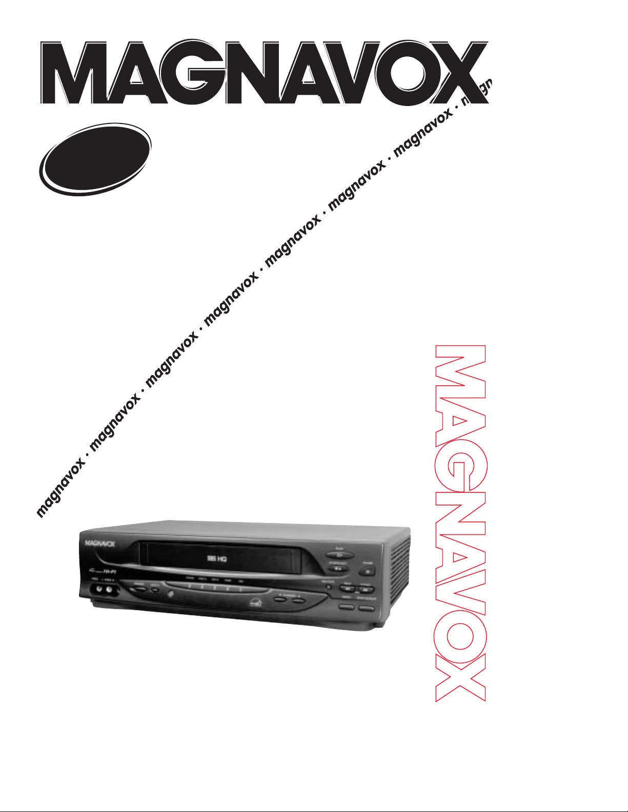
The basic VCR/TV connection – antenna/cable to VCR to TV – is shown below. If you have a
Cable Box or a Direct Broadcast System, please see pages eight-nine. If you have a Stereo
TV, please see page 10. After you hook up the VCR, go to page 11 to turn on the VCR.
(The VR601BMG is illustrated here. The VR401BMG has single AUDIO IN/OUT jacks.)
ANTENNA IN
Jack
(on back of TV)
Cable
(75 ohm)
Back of VCR
Antenna
Indoor/Outdoor
(300 ohm)
1
Disconnect the antenna or cable from your TV.
2
Connect the antenna or cable to the ANT(enna) IN Jack of your VCR.
Cable
(75 ohm)
Antenna
Indoor/Outdoor
(300 ohm)
Page 3
CH3CH4
OUT
IN
ANT
AUDIO
R
L
VIDEO
OUT
IN
INOUT
CH 4
or
CH 3
CH3
CH4
OUT
IN
ANT
CH3 / CH4
Switch
CH3 CH4
AUDIO
R
L
VIDEO
OUT
IN
IN
OUT
CH3CH4
OUT
IN
ANT
AUDIO
R
L
VIDEO
OUT
IN
INOUT
75V
ANT /
CABLE
75
ANT /
CABLE
CH3
CH4
OUT
IN
ANT
AUDIO
R
L
VIDEO
OUT
IN
IN
OUT
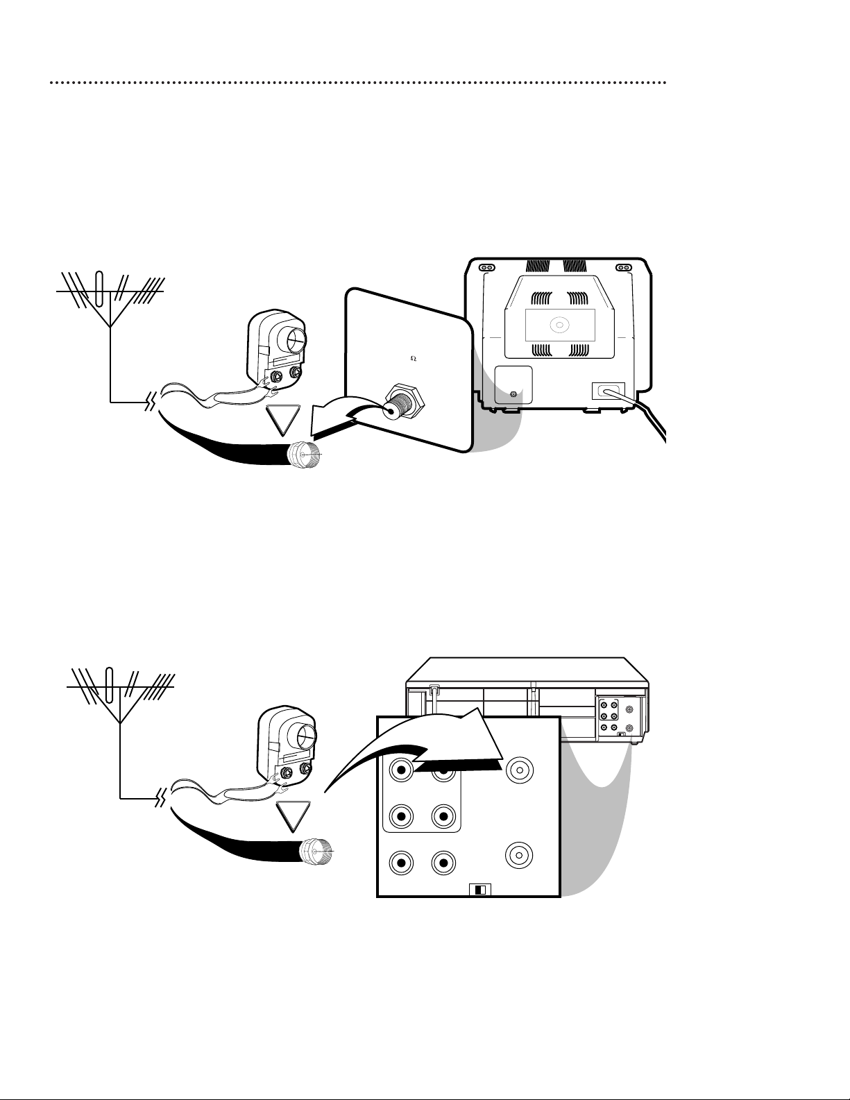
RF coaxial cable
Antenna
or Cable
3
Connect the RF coaxial cable (supplied) to the OUT Jack on the back of the
VCR and to the ANTENNA IN Jack on the TV. (You may use either a snap-on
type (supplied) or screw-on type of coaxial cable, whichever you prefer.)
5
Set the CH3/CH4 switch on the back of the VCR to CH3 or CH4, whichever
channel is not used or least used in your area. Set the TV to the same channel. For
example, when playing a tape, if the CH3/CH4 switch is set to CH3, the TV should be on
channel 03.
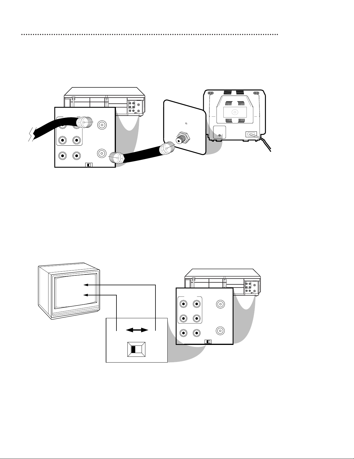
Hookups Without a Cable Box/Direct Broadcast System (cont’d) 7
ANTENNA IN Jack
(on back of TV)
example only
4
Plug in the TV and the VCR.
6
You are ready to turn on the VCR. Please go to page 11 before turning on the
VCR.
Page 4

8 Hookups With a Cable Box/Direct Broadcast System
There are two ways to connect your Cable Box/DBS to the VCR. With this connection:
● You may view any channel.
● You must select channels at the Cable Box/DBS. Channels cannot be changed at the VCR.
● You may not view a channel other than the one you are recording.
● You may not program channels at the VCR.
● You can only program a timer recording for one channel at a time. Set the TV and the VCR to the Cable
Box/DBS output channel (channel 03 or 04); set the CH3/CH4 switch to the same channel. Set your Cable
Box/DBS to the channel you want to record. When you enter the channel you want to record in a timer
recording, select channel 03 or 04 (the Cable Box/DBS output channel). (This is step 5 on page 29.) Leave the
Cable Box/DBS on for a timer recording.
AUDIO
R
L
VIDEO
OUT
IN
IN
OUT
CH3 CH4
OUT
IN
ANT
OUT
IN
75
ANT /
CABLE
TV’s
ANTENNA IN
Jack
Cable Box/DBS
VCR
Recording/Viewing Any Channel
Connections
1
With the VCR on and in VCR position (the VCR/TV light will appear on the display panel), use the CHANNEL o/p buttons to set the VCR to the
Cable Box/DBS output channel (channel 03 or 04). Set the CH3/CH4
switch to the same channel.
2
Set the TV to the same channel to which you set the VCR.
3
Select the channel you want to view/record at the Cable Box/DBS.
1
Connect a Cable signal to the IN Jack on the Cable Box/DBS.
2
Use an RF coaxial cable (supplied) to connect the OUT Jack on the Cable
Box/DBS to the ANT(enna) IN Jack on the VCR.
3
Use a second RF coaxial cable to connect the OUT Jack on the VCR to the
TV’s ANTENNA IN Jack.
1
2
3
Cable
Signal
RF coaxial
cable
RF coaxial
cable
Page 5

Hookups With a Cable Box/Direct Broadcast System (cont’d) 9
R
L
VIDEO
IN
OUT
IN
OUT
AUDIO
CH3CH4
OUT
IN
ANT
IN
OUT
75
ANT /
CABLE
With this connection:
● You may watch one channel while recording another.
● You may not record scrambled channels.
Recording One Channel/Watching Another
1
Put the Cable Box/DBS on the same channel as the
VCR’s CH3/CH4 switch. Set the TV to the Cable
Box/DBS output channel (03 or 04).
Then, with the VCR in VCR position (the VCR/TV light will
appear on the display panel), use the CHANNEL o/p but-
tons to select the channel you want to record at the
VCR. Start the recording.
2
Press the VCR/TV button once to put the VCR in TV
position. (The VCR/TV light will disappear.)
3
Select the channel you want to watch at the Cable
Box/DBS.
TV’s ANTENNA
IN Jack
Cable Box/DBS
VCR
• When you play a tape, make sure
the Cable Box/DBS is set to the
same channel as the CH3/CH4
switch on the VCR. Set the TV to
the Cable Box/DBS output channel
(03 or 04).
Helpful Hint
1
Connect a Cable signal to the VCR’s ANT(enna) IN Jack.
2
Use an RF coaxial cable (supplied) to connect the OUT Jack on
the VCR to the IN Jack on the Cable Box/DBS.
3
Use a second RF coaxial cable to connect the OUT Jack on the
Cable Box/DBS to the ANTENNA IN Jack on the TV.
1
2
3
Connections
Cable
Signal
RF coaxial
cable
RF coaxial
cable
Page 6

10 Hookups with a Stereo TV
● Audio and Video cables are not supplied.
1
Connect the antenna or cable to the ANT(enna) IN Jack on the back of the VCR.
2
Connect a video cable to the yellow VIDEO OUT Jack on the back of the VCR. Then, connect
the other end of the video cable to the VIDEO IN Jack on your TV.
3
VR601BMG: Connect a stereo audio cable to the red and white AUDIO OUT Jacks on the back
of the VCR, matching cable colors to the jack colors. Then, connect the other end of the audio
cable to the AUDIO IN Jacks on your TV, again matching cable colors to the jack colors.
VR401BMG: Connect an audio cable to the white AUDIO OUT Jack on the back of the VCR.
Then, connect the other end of the audio cable to the AUDIO IN Jack on your TV.
(If your TV has Right and Left AUDIO IN Jacks, you must use a “Y” splitter audio cable as illustrated to deliver
audio to the TV’s right and left channels.) This hookup will not give you stereo sound. To get stereo sound, use
the connections on pages six - seven and select the channel to be viewed at the TV (with the VCR turned off).
4
Turn on your TV, making sure it is in Line Input mode. Please refer to your TV owner’s manual for details.
CH3CH4
OUT
IN
ANT
AUDIO
R
L
VIDEO
OUT
IN
INOUT
antenna or
cable to
ANT(enna)
IN Jack
Video Cable
Stereo Audio Cable
VIDEO (yellow) and
AUDIO (red and white)
OUT Jacks
Audio and Video
IN Jacks on TV
1
2
3
VR601BMG
VIDEO
IN
OUT
CH3CH4
AUDIO
OUT
IN
ANT
antenna or
cable to
ANT(enna)
IN Jack
Video Cable
Audio Cable
VIDEO (yellow) and
AUDIO (white) OUT Jacks
Audio and Video
IN Jacks on TV
1
2
3
VR401BMG
Page 7

22 Front Panel
PAUSE Button
While recording, press to pause the recording. Press
again to resume recording. Details are on page 25. You
can not pause a One-Touch Recording. During tape
playback, press to freeze the picture. Press again to
resume playback. Details are on page 36.
POWER Button
Press to turn the
VCR power on and off.
VCR/TV Button
Press to select VCR or TV position.
● VCR Position
Use to watch a tape, to watch a program
while recording it, or to watch a TV program (changing channels at the VCR). When
the VCR/TV light appears on the display
panel, the VCR is in VCR position.
● TV Position
Use to watch TV (changing channels at the
TV) or to watch one program while recording another. When the VCR/TV light does
not appear on the display panel, the VCR is
in TV position.
REC(ord)/OTR Button
Press once to start a recording. Press
repeatedly to start a One-Touch
Recording. Details are on page 27.
CHANNEL (p/o) Buttons
Press to change channels at the VCR.
Or, press to adjust the tracking of a
tape during normal playback or slow
motion playback. Also, press to
remove vertical jitter in a Still picture.
PLAY Button
Press to play a tape. Press to release Slow,
Search, or Still mode and return to playback. Details are on page 36. Press to
select an item in the menu.
REW(ind) Button
When playback is stopped, press to
rewind the tape at high speed.
During playback, press to rewind the
tape while the picture stays on the
screen. Details are on page 36. Press
to return to a previous menu.
STOP/EJECT Button
Press once to stop the tape. When playback is stopped,
press to eject the tape. Press to select an item in the menu.
F.FWD (Fast Forward) Button
When playback is stopped, press to fast forward the tape at
high speed. During tape playback, press to fast forward the
tape while the picture stays on the screen. Details are on
page 36. Press to advance to the next menu or to change
the setting of an item in the menu.
STOP/EJECT
REC/OTR
MENU
STATUS/EXIT
F.FWD
PAUSE
REW
CHANNEL
PLAY
POWER
POWER
VCR/TV
VCR/TV
CST.IN TIMER REC
VIDEO L - AUDIO -R
Remote Sensor
Receives a signal from your
remote control so you can operate your VCR from a distance.
VR601BMG
AUDIO In Jacks
Connect audio cables coming from the audio out jacks
of a camcorder, another
VCR, or an audio source
here. Details are on page 32.
The VR601BMG is shown
here. The VR401BMG has
only one AUDIO IN jack.
VIDEO In Jack
Connect a cable coming from the video
out jack of a camcorder, another VCR,
or an audio-visual
source (laser disc
player, video disc
player, etc.) here.
Details are on page 32.
MENU Button
Press to access the VCR menu.
STATUS/EXIT Button
Press to access or remove the on-screen status display.
Details are on page 20. Press to exit on-screen menus.
Page 8

AUDIO IN Jacks
Connect audio cables coming from the
AUDIO OUT Jacks of a camcorder,
another VCR, or an audio source here.
Details are on page 32.
The VR601BMG is shown here. The
VR401BMG has only one AUDIO IN jack.
VIDEO IN Jack
Connect a video cable coming
from the VIDEO OUT Jack of a
camcorder, another VCR, or an
audio-visual source (laser disc
player, video disc player, etc.)
here. Details are on page 32.
ANT(enna) IN Jack
Connect your antenna or cable
here. Details are on pages six-10.
CH3/CH4 Switch
Set to channel 3 or 4
to use your TV with
your VCR. Details are
on pages six-nine.
OUT Jack
Use the supplied RF coaxial cable to connect this
jack to the ANTENNA IN
Jack on your TV, Cable
Box, or Direct Broadcast
System. Details are on
pages six-nine.
VIDEO OUT Jack
Connect a video cable going to the VIDEO
IN Jack of a camcorder, another VCR, or an
audio-visual system (monitor, laser disc player, video disc player, etc.) here. Details are on
pages 32 and 38.
AC Power Cord
Connect to a standard AC outlet to
supply power to the
VCR.
AUDIO OUT Jacks
Connect audio cables going to the AUDIO IN
Jacks of a camcorder, another VCR, or an audio
system here. Details are on pages 32 and 38.
The VR601BMG is shown here. The VR401BMG has
only one AUDIO OUT jack.
CH3 CH4
OUT
IN
ANT
AUDIO
R
L
VIDEO
OUT
IN
INOUT
Rear Panel 23
VR601BMG
Page 9

1
Make the connections shown above.
32 Rerecording (Tape Duplication)
3
VCR 2 will record your tape. Insert a blank tape in VCR 2. The
VCR must be in VCR position. (The VCR/TV light will appear on the
display panel. If it does not, press the VCR/TV button once.)
4
Turn on the TV and set it to channel 03 or 04, whichever
channel the CH3/CH4 switch on VCR 2 is set to.
5
Point the remote control at VCR 2. Press the Number
buttons 0, 0, 1 or 0, 0, 2. (See Helpful Hints at right.)
6
Press the SPEED button to select SP or SLP at VCR 2.
7
Press the PLAY button on VCR 1 and the REC(ord)/OTR
button on VCR 2 at the same time.
To stop recording, press the STOP/EJECT button on VCR 1, then
press the STOP/EJECT button on VCR 2.
CH3 CH4
OUT
IN
ANT
AUDIO
R
L
VIDEO
OUT
IN
INOUT
CH3 CH4
OUT
IN
ANT
R
L
VIDEO
IN
OUT
IN
OUT
AUDIO
VCR 1
Playing VCR
VCR 2 - Recording VCR
2
VCR 1 will play your tape. Put a prerecorded tape in VCR 1.
1. Audio cables from AUDIO OUT Jacks
of VCR 1 to AUDIO IN Jacks of VCR 2
2. Video cable from VIDEO OUT Jack
of VCR 1 to VIDEO IN Jack of VCR 2
3. RF coaxial cable
from the OUT jack of
VCR 2 to the TV’s
ANTENNA IN Jack
• If you use the AUDIO and VIDEO IN
Jacks on the back of VCR 2, press
Number buttons 0, 0, 1 at step 5.
AV REAR will appear on the screen.
• If you use the AUDIO and VIDEO In
Jacks on the front of VCR 2, press
Number buttons 0, 0, 2 at step 5.
AV FRONT will appear on the
screen.
• Unauthorized recording of copyrighted television programs, video tapes,
or other materials may infringe on
the rights of copyright owners and
violate copyright laws.
• If a program has copyright protection, it may not record clearly.
• These instructions show you how to
copy tapes using two VCRs like
yours. Different VCRs may operate
differently.
• The VCR in the figure above is the
VR601BMG. If you have the
VR401BMG, use a single-plug audio
cable to connect the AUDIO OUT
jack on VCR 1 to the AUDIO IN jack
on VCR 2.
Helpful Hints
● Audio and Video cables are not supplied.
The instructions on this page show you how to copy tapes. The illustration uses two VR601BMG VCRs.
Different VCRs may operate differently. To duplicate a tape, make the connections shown, then follow steps 1-7.
 Loading...