

Magnavox U26-O1AA, U26-O3AA, U26-O2AA, U26-O4AA, V26-O1AA Disassembly Instructions Manual
...Page 1
PHOTOFACT*
Fold
er
MAGNAVOX
-O4AA,
V26-O1AA,
AMP-142CC,
CHASSIS
U26-O1AA, -O2AA, -O3AA,
-O2AA, -O3AA, -O4AA,
AMP-169AA,
CR-745BB
(26
Series)
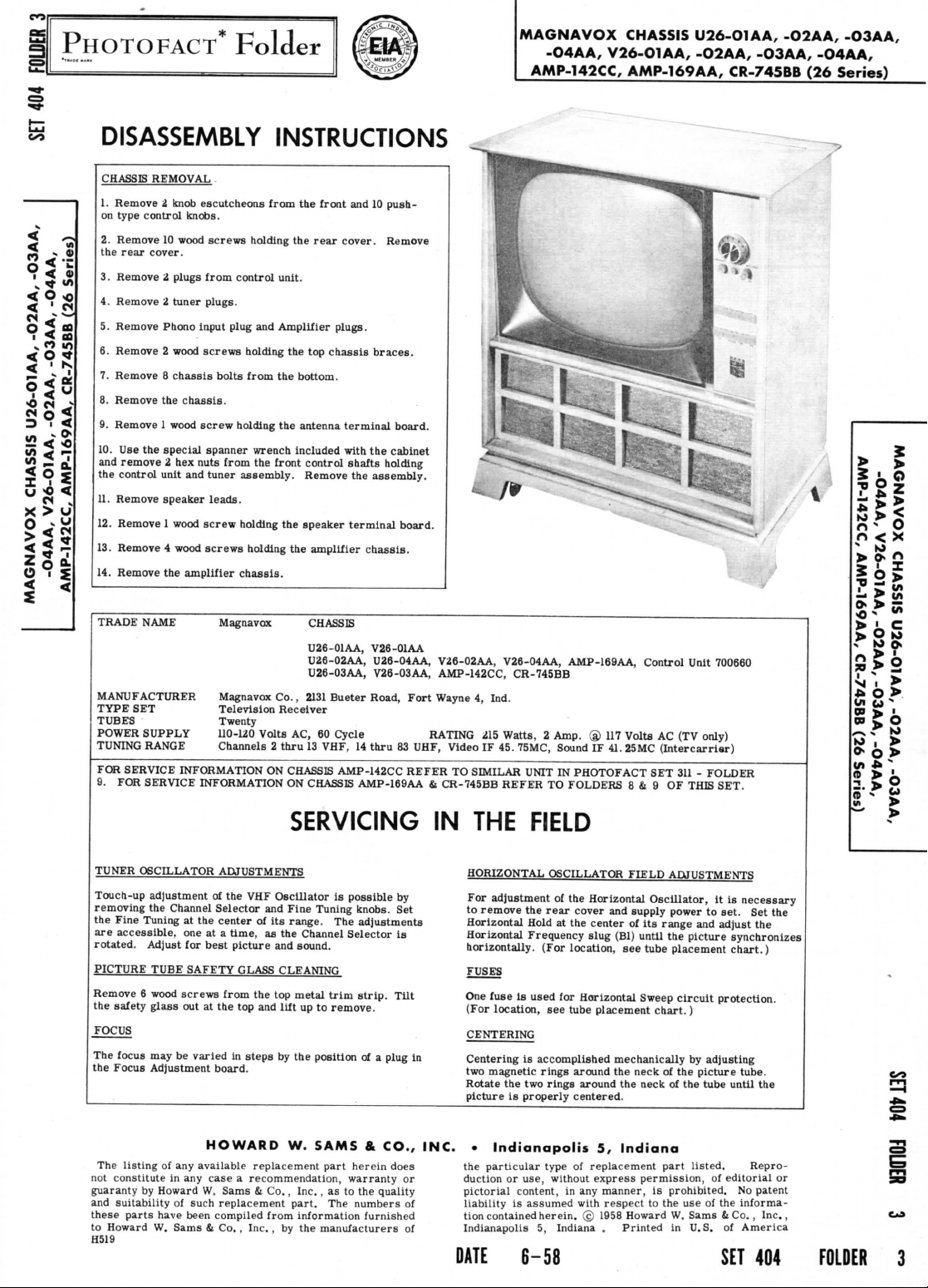
DISASSEMBLY
CHASSIS
REMOVAL
1.
Remove 2 knob
on
type
control
2.
Remove
the
rear
cover.
3.
Remove i plugs from
4.
Remove 2 tuner
5.
Remove Phono input plug
6.
Remove 2 wood
7.
Remove 8 chassis
8.
Remove
9.
Remove 1 wood
10.
Use the
and
remove
the
control
11.
Remove
12.
Remove 1 wood
13.
Remove 4 wood
14.
Remove
TRADE
NAME
MANUFACTURER
TYPE
SET
TUBES
Twenty
POWER
SUPPLY
TUNING
RANGE Channels 2 thru
FOR
SERVICE INFORMATION
9. FOR
SERVICE INFORMATION
escutcheons
knobs.
10
wood
screws
control
plugs.
screws
holding
bolts
the
chassis.
screw
holding
special
spanner
2 hex
nuts from
unit
and
tuner
assembly.
speaker
leads.
screw
holding
screws
the
amplifier
Magnavox CHASSIS
Television
chassis.
Magnavox
110-120
INSTRUCTIONS
from
the
front
and 10
push-
holding
the
rear
cover.
Remove
unit.
and
Amplifier
from
the
the
wrench included with
the
front
holding
Co.,
Receiver
Volts
ON
plugs.
the top
chassis
braces.
bottom.
antenna
terminal
control
Remove
the
speaker
the
amplifier
U26-01AA,
U26-02AA,
U26-03AA,
2131
Bueter
AC,
60
Cycle
13
VHF,
CHASSIS AMP-142CC REFER
ON
CHASSIS AMP-169AA & CR-745BB REFER
board.
the
cabinet
shafts holding
the
assembly.
terminal
board.
chassis.
V26-01AA
U26-04AA, V26-02AA, V26-04AA, AMP-169AA,
V28-03AA, AMP-142CC, CR-745BB
Road,
RATING
14
thru
83
SERVICING
Fort
Wayne
UHF, Video
TO
IN THE
4,
Ind.
215
Watts, 2 Amp.
IF 45.
SIMILAR
75MC, Sound
UNIT
IN
PHOTOFACT
TO
FOLDERS
FIELD
® 117
IF 41.
Control
Volta
AC (TV
25MC
(Intercarrier)
SET 311 -
8 & 9 OF
Unit
700660
only)
FOLDER
THIS SET.
r>
-
r>
< X
IS!
zi
£8?
m
> O
*>§
w i >
O
>
=.
>
i
Ul
^
I
O
TUNER
OSCILLATOR ADJUSTMENTS
Touch-up
adjustment
removing
the
the
Fine
Tuning
are
accessible,
rotated.
Adjust
PICTURE
Remove 6 wood
the
FOCUS
The
the
not
guaranty
and
these
to
H519
TUBE SAFETY GLASS
safety
glass
focus
may be
Focus
Adjustment
The
listing
constitute
by
Howard
suitability
parts
Howard
have been compiled
W.
of the VHF
Channel
Selector
at the
one at a
for
best
screws
out at the top and
varied
board.
HOWARD
of any
available replacement part herein
in any
case a recommendation, warranty
W.
of
such replacement
Sams & Co.,
and
center
of its
time,
as the
picture
from
the top
in
steps
Sams & Co.,
from
Inc.,
HORIZONTAL
Oscillator
and
CLEANING
lift
by the
by the
is
Fine Tuning knobs.
range.
metal
W.
part.
possible
The
Channel
sound.
trim
up to
remove.
position
SAMS & CO., INC. • Indianapolis
Inc.,
as to the
The
information
manufacturers
adjustments
Selector
strip.
Tilt
of a
plug
does
quality
numbers
furnished
by
Set
is
or
of
of
In
For
adjustment
to
remove
Horizontal
Horizontal
horizontally.
FUSES
One
fuse
(For
location,
CENTERING
Centering
two
magnetic
Rotate
picture
the
particular type
duction
pictorial content,
liability
tion
contained
Indianapolis
DATE
6-58
OSCILLATOR FIELD ADJUSTMENTS
of the
the
Hold
Frequency
Is
used
is
accomplished mechanically
the two
is
properly
or
use,
is
assumed
5,
Horizontal
rear
cover
at the
center
slug
(For
location,
for
Horizontal
see
tube
placement
rings
around
rings
around
centered.
5,
of
replacement part
without
express
in any
with
herein. © 1958 Howard
Indiana . Printed
and
supply
of
(Bl)
until
see
Sweep
the
neck
the
neck
Indiana
permission,
manner,
respect
Oscillator,
its
tube
chart.)
is
to the use of the
power
to
range
and
the
picture
placement
circuit
by
of the
picture
of the
tube until
listed.
prohibited.
W.
Sams & Co.,
in
U.S.
it is
necessary
set.
Set the
adjust
synchronizes
chart.)
protection.
adjusting
tube.
Repro-
of
editorial
No
informa-
of
America
SET
the
the
or
patent
Inc.,
404
FOLDER
3
Page 2
ADDITIONAL
SCHEMATIC
PAGE
VHP
TUNER
*700662-1&
UHF-VHF
TUNER
UHF
TUNER
1700530-3
DC
COIL
NOT
SHOWN
ARROWS
(CONTROL
WAVEFORMS
SET
TO
PEAK
SIGNAL
,
nr
vol
per
Pin
2
bot
SCHEMATICS
*700663-1
RESISTANCE
ON
ON
CONTROLS
VIEWED
TAKEN
PRODUCE
AT
voltage
meter;
volt.
numbe
torn
of
socket.
VALUES
SCHEMATIC
INDICATE
FROM
WITH
CONTROLS
50
VOLTS
PICTURE
TUBE.
measurements taken
AC
voltage
measured
UNDER
DIAGRAM
.CLOCKWISE
SHAFT
PEAK-TO-
with
vacuum
at
1000
ONE OHM
END)
tube
ohms
ROTATION
-asured
va
3
M
unless otherwise stated.
4.
Li
ie
Voltage
5.
A
controls
set
A
PHOTOFACT STANDARD
ues
ore
maintained
for
normal
How.,J
from
socket
at
W.
S.m, I Co.,
pinto common
117
volts
operat.on
NOTATION
for
no
I.e.
voltage
signal
1958
negative
readings.
applied.
SCHEMATIC
PAGE
2
Page 3
USED
IN I 22K
CHASSIS A 1W
26-01AA
-X
1
T^v
240V
\L
PLUC
&
SOCKET
AGC
CLAMPER
®6AT6
12
VOLTAGE
®
6DG6GT
DIVIDER
MAGNAVOX
CHASSIS
-O4AA, V26-O1AA, -O2AA, -O3AA, -O4AA,
AMP-142CC,
U26-O1AA,
AMP-169AA,
-O2AA,
CR-745BB
(26
Series)
PAGE
-O3AA,
19
Page 4
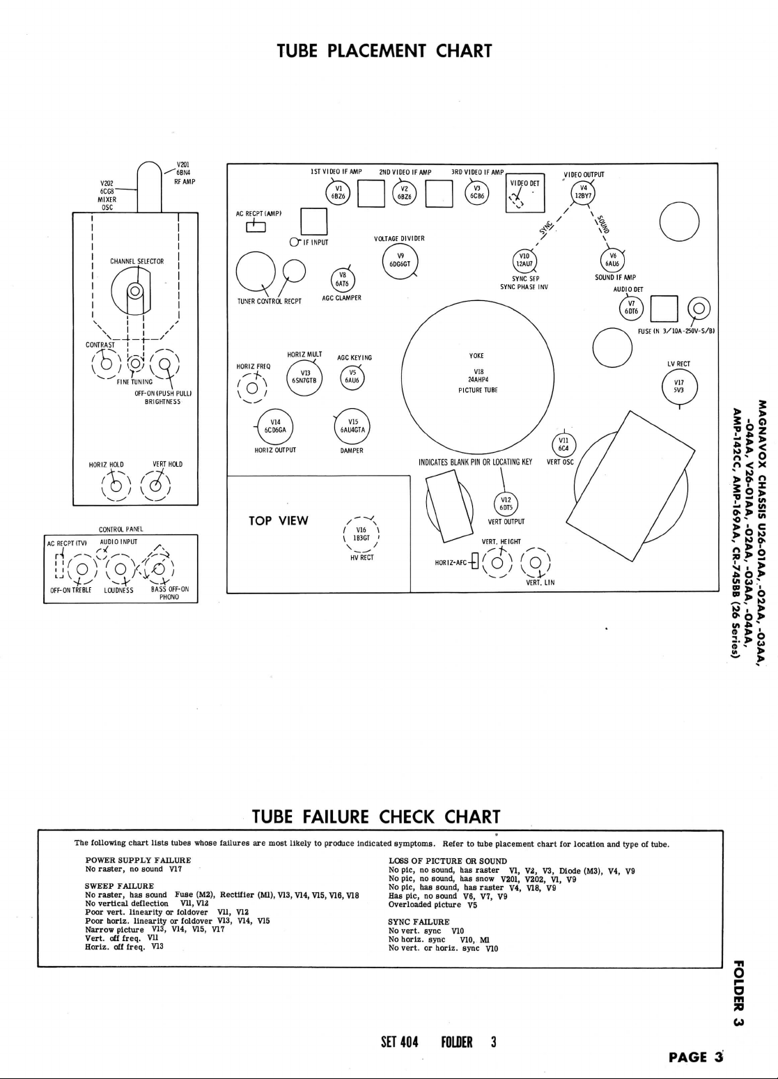
TUBE
PLACEMENT
CHART
AC
RECPT
ri/-
OFF-
VZOZ
6CG8~
MIXER
OSC
HORIZ HOLD VERT HOLD
\o/
AUDIO
INPUT
' V ^
LOUDNESS
ON
ITVI
TREBLE
OFF-ON
(PUSH
BRIGHTNESS
\L
PANEL
f^
BASS OFF-ON
PHONO
VZ01
RFAMP
PULL)
AC
RECPT
1AMPI
±]
J
V14 \ V15
"1
6CD6GA I ^
HORIZ
OUTPUT DAMPER
TOP
VIEW
1STVIDEOIFAMP
6AU4GTA
2ND
VaTAGE
VIDEO
DIVIDER
/T\
>—s*
IF AMP 3RD
60G6GT
I
HORIZ-AFC^ ^ (J
VIDEO
IF AMP
) ( O )
>
>
S ' O
7gz
n
- O
n
< X
in u '
01 > '
w
C O
The
following
POWER
SUPPLY FAILURE
No
raster,
SWEEP FAILURE
No
raster,
No
vertical
Poor
vert,
Poor
horiz.
Narrow
picture
Vert,
off
Horiz.
off
chart
no
sound
has
sound
deflection
linearity
linearity
freq.
Vll
freq.
lists
V13,
V13
tubes
whose
V17
Fuse
(M2),
VII,
or
foldover
or
foldover V13,
V14,
V15,
V12
failures
Rectifier
Vll,
V17
TUBE FAILURE CHECK
are
most
likely
to
produce indicated
(Ml),
VIS.W,
V15,
V16.V18
V12
V14,
V15
symptoms.
LOSS
OF
No
pic,
no
No
pic,
no
No
pic,
has
Has
pic,
no
Overloaded
SYNC
FAILURE
No
vert,
sync
No
horiz.
No
vert,
or
CHART
Refer
to
PICTURE
OH
sound,
has
sound,
has
sound,
has
sound
V6,
picture
V5
V10
sync
V10,
horiz.
sync
tube placement
SOUND
raster
VI,
snow
V201,
raster
V4,
VI,
V9
Ml
V10
V2,
V202,
V18,
chart
V3,
V9
for
Diode
VI,
location
(M3),
V9
and
type
V4, V9
9
>
n
i
to. O
»'-
y
Wl
>
of
tube.
O
s
70
SET
404
FOLDER
3
PAGE
3
Page 5
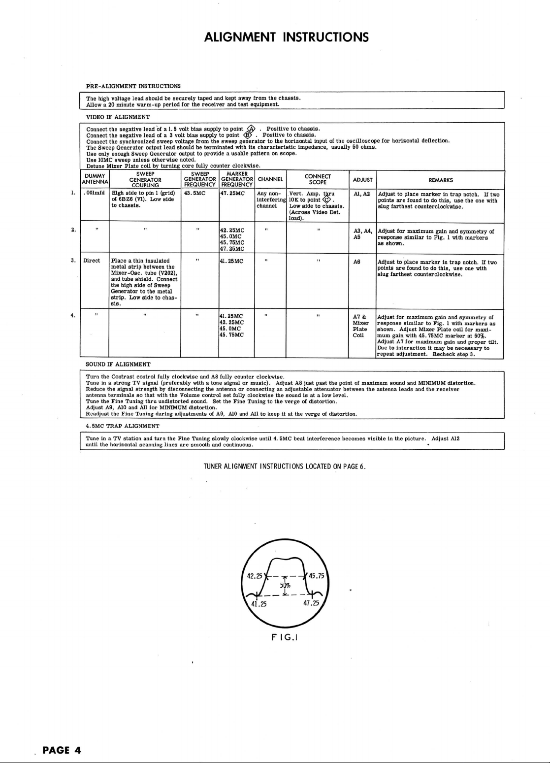
ALIGNMENT
INSTRUCTIONS
PRE-ALIGNMENT
The
high
voltage lead should
Allow
a 20
minute warm-up period
VIDEO
IF
ALIGNMENT
Connect
the
the
the
Sweep
only
enough
10MC
sweep unless
Mixer
High
of
to
Place a thin
metal
Mixer
and
the
Generator
strip.
sis.
IF
the
Contrast control
in a
strong
the
terminals
the
Fine
A9,
the
SMC
TRAP
in a TV
the
horizontal
negative lead
negative
synchronized
Generator
6BZ6
chassis.
tube
high
ALIGNMENT
signal strength
AID
Fine
Connect
Connect
The
Use
Use
Detune
DUMMY
ANTENNA
.
OOlmfd
Direct
SOUND
Turn
Tune
Reduce
antenna
Tune
Adjust
Readjust
4.
Tune
until
INSTRUCTIONS
lead
output
Sweep
Generator
otherwise
Plate
coil
SWEEP
GENERATOR
COUPLING
side
to
pin 1 (grid)
(VI).
Low
"
insulated
strip
between
-Osc.
tube
shield.
side
of
to the
Low
side
TV
signal
so
that
Tuning
thru
and All for
Tuning
ALIGNMENT
station
and
scanning
be
securely taped
for the
of a
1. 5 volt
volt
Was
voltage
lead should
output
noted.
GENERATOR
FREQUENCY
43.
side
the
chas-
clockwise
disconnecting
the
Volume
the
Fine
lines
are
Was
SWEEP
SMC
with a tone signal
sound.
distortion.
Tuning
smooth
of a 3
sweep
by
turning core
(V202),
Connect
Sweep
metal
to
fully
(preferably
by
with
undistorted
MINIMUM
during adjustments
turn
and
kept
receiver
supply
supply
from
be
terminated
to
provide a usable pattern
fully
"
and A8
the
control
away
and
test
to
point
<A> . Positive
to
point
the
counter clockwise.
Set the
of A9,
<3|> . Positive
sweep
generator
with
MARKER
GENERATOR
FREQUENCY
47.
25MC
42.
25MC
45.0MC
45.
75MC
47.25MC
41. 25 MC
41.25MC
42.
25MC
45. OMC
45.
75MC
fully
counter clockwise.
or
antenna
or
connecting
set
fully
clockwise
Fine
A10
and All to
slowly clockwise until
and
continuous.
from
the
chassis.
equipment.
to
chassis.
to
chassis.
to the
its
music).
Tuning
horizontal input
characteristic
CHANNEL
Any
interfering
channel
•
impedance, usually
on
scope.
non-
Vert. Amp.
10K
Low
(Across Video Det.
load).
Adjust
A8
an
adjustable
the
sound
to the
verge
keep
it at the
4.
BMC
beat interference becomes visible
CONNECT
SCOPE
to
point
side
to
just
past
attenuator
is at a low
of
distortion.
verge
of the
thru
<@>
.
chassis.
"
the
of
distortion.
oscilloscope
point
between
level.
for
50
ADJUST
Al, A2
A3,
A5
A6
A7&
Mixer
Plate
CoU
of
ohms.
horizontal deflection.
Adjust
to
points
are
slug farthest counterclockwise.
A4,
Adjust
for
response
as
shown.
Adjust
to
points
are
slug farthest counterclockwise.
Adjust
for
response
shown.
mum
gain
Adjust
A7 for
Due
to
interaction
repeat adjustment. Recheck
maximum
sound
the
antenna
in the
place marker
found
to do
maximum gain
similar
place marker
found
to do
maximum
similar
Adjust
Mixer
with
45.
maximum gain
and
MINIMUM
leads
and the
picture.
REMARKS
in
this,
to
Fig. 1 with
in
this,
gain
to
Fig. 1 with
Plate
75MC
it may be
receiver
Adjust
trap
notch.
use the one
and
symmetry
trap
notch.
use one
and
symmetry
coll
marker
and
necessary
step
distortion.
A12
If two
markers
If two
with
markers
for
maxi-
at
50%.
proper
3.
to
with
of
of
as
tilt.
PAGE
4
TUNER
ALIGNMENT
INSTRUCTIONS LOCATED
F
IG
ON
PAGE6.
Page 6
A
PHOTOFACT
VALUE
OR
STANDARD
Howard
W.
APPLICATION
S.ms
S,
NOTATION
Co.,
Inc. 1958
SCHEMATIC
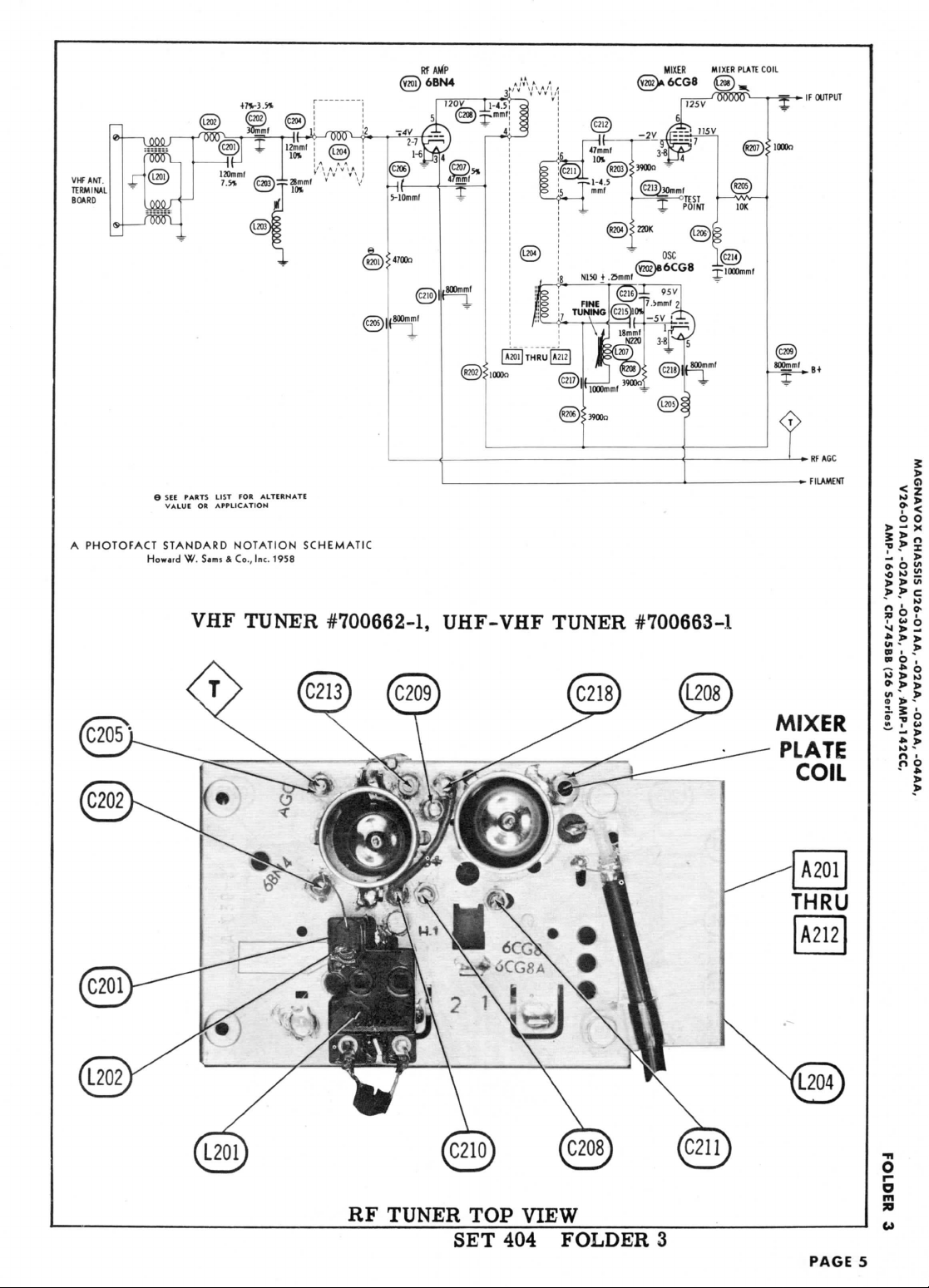
MIXER
Y2ffl>6CG8
MIXER
PLATE
COIL
VHF
TUNER
#700662-1, UHF-VHF
TUNER
#700663-1
MIXER
PLATE
COIL
RF
TUNER
TOP
VIEW
SET 404
FOLDER
3
PAGE
5
Page 7
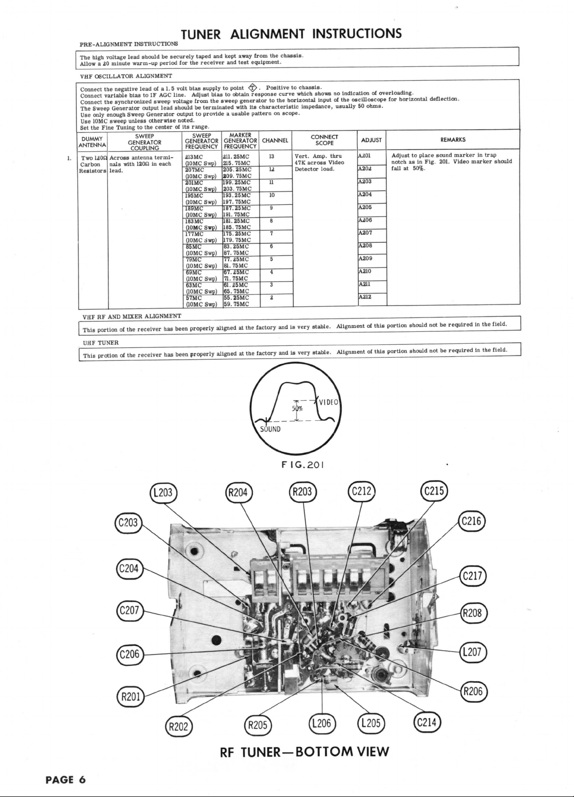
PRE-ALIGNMENT
The
high
Allow
a 20
VHP
OSCILLATOR
Connect
the
Connect
variable
Connect
The
Sweep
Use
only enough Sweep
Use
10MC sweep
Set
the
Fine
DUMMY
ANTENNA
Two
UOS1
Carbon
Resistors
VHF
RF AND
This
portion
UHF
TUNER
_
.
This
protion
INSTRUCTIONS
voltage lead
the
lead.
should
minute
warm-up
ALIGNMENT
negative
lead
bias
to IF AGC
synchronized sweep voltage
Generator
output
Generator
unless
Tuning
Across
nals
otherwise noted.
to the
SWEEP
GENERATOR
COUPLING
antenna
with
12012
in
MIXER
ALIGNMENT
of the
receiver
_^________
of the
receiver
TUNER
be
securely
period
for the
of a 1, 5
volt
bias
line.
Adjust
lead should
output
center
of its
GENERATOR
FREQUENCY
termi-
213
each
(10MC
207MC
(10MC
201MC
(10MC
195MC
(10MC
189MC
(10MC
183MC
(10MC
177MC
(10MC
85MC
(10MC
79MC
(10MC
69MC
(10MC
63MC
(10MC
57MC
(10MC
has
been properly aligned
has
been
properly
range.
ALIGNMENT
taped
and
kept
receiver
supply
from
be
terminated with
to
provide a usable
SWEEP
MC
Swp)
Swp)
Swp)
Swp)
Swp)
Swp)
;iwp)
Swp)
Swp)
Swp)
Swp)
Swp)
away
and
test
to
point
bias
to
obtain response curve
the
sweep generator
MARKER
GENERATOR
FREQUENCY
211.25MC
215.75MC
205.25MC
209.
75MC
199.
25MC
203.75MC
193.25MC
197.
75MC
187.
25MC
191.
75MC
181.
25MC
185.
75MC
175.25MC
179.
75MC
83.25MC
87.
75MC
77.25MC
81.
75MC
67.25MC
71.75MC
61. 2
SMC
65.
75MC
55.25MC
59.
75MC
at the
aligned
at the
from
the
chassis.
equipment.
^> . Positive
to the
its
characteristic
pattern
on
CHANNEL
13
u
u
10
9
8
7
6
5
4
3
2
factory
and is
—
factory
and is
INSTRUCTIONS
to
chassis.
which
horizontal
impedance, usually
scope.
Vert. Amp. thru
47K
across
Detector load.
very
stable.
very
stable.
shows
input
CONNECT
SCOPE
Video
Alignment
Alignment
no
indication
of the
of
overloading.
oscilloscope
50
ohms.
ADJUST
(U01
A204
A203
A204
A205
A206
A207
A208
A209
A210
A211
A212
of
this
of
this
for
horizontal deflection.
Adjust
to
place sound marker
notch
as in
Fig. 201.
fall
at
50%.
portion should
portion
should
not be
not be
REMARKS
Video
required
required
in
trap
marker should
in the
field.
in the
field.
FIG.201
RF
TUNER-BOTTOM
VIEW
PAGE
6
Page 8

AFINPUT(
TV
PH
hPHONO
INPUT
135V
•£_
CONTROL
&
SOCKET
Howard
.01
PLUG
W.
«
S.m,*
TOR24
A
PHOTOFACT STANDARD
CONTROL PLUG
&
3»
VOLUMiL
1220135-1
CONTROL PLUG
&
SOCKET
^~>
If
4-
NOTATION
Co.,
AUDIO
SOCKET
»2
\A7
fl
5000™,
So-\(
4r
4.7meg
II
2
UHF
1000
VER
VERSIONS-
JT
BRIGHTNESS
200K
PART
1220132-2
SCHEMATIC
Ire.
1958
CIRCUIT USED
AF
AMP AGC
CLAMPER
6AT6
-135V 270V
CONTROL
PLUG
SOCKET
TERMINAL
GUIDE
12
CONTROL PLUG
&
£
TP
WOOnmf
IN CH.
AUDIO
U/V26-01AA
OUTPUT
6DG6GT
275V
<2
o o
>
- X
» ° »
o
10
!£
j, > u>
> > C
K>
—
* o
UHF
TUNER
TOP
VIEW
SET 404
FOLDER
3
PAGE
7
O
r~
O
m
30
W
Page 9

C27
PAGE
8
CHASSIS
BOTTOM
VIEW - CAP
AC!
Page 10

o 0
J>
-*
» o <*
./>
to
j. > ui
So
«
* o
"•>
» > J,
X
!£
M
ACITOR & ALIGNMENT
IDENT.
PAGE
O
5
13
Page 11

PAGE
12
CHASSIS BOTTOM VIEW
- RES
Page 12

o
II
If
?8
25
ui
-
5
b
M
>
O-
j>
if
>
lESISTOR
&
INDUCTOR
IDENT.
SET
404
FOLDER
3
PAGE
9
O
m
Page 13

ITEM
No.
VI
V2
V3
V4
V5
V6
V7
V8
ITEM
No.
V18
ITEM
No.
CIA
B
C
D
C2A
B
C
D
C3
•Non-catalog
ITEM
No.
C4
C5
ca
07
C8
C9
CIO
01
C12
CIS
C14
C15
C16
C17
CIS
09
C20
C21
C22
C23
C24
C25
C26
C27
C28
C29
C30
C31
C32
C33
C34
C35
C36
C37
C38
C39
C40
C1I
C42
C43
C44
C45
C46
C47
C48
C49
C50
C51
C52
C53
C54A
B
ITEM
No.
R1A
B
R2
R3A
B
R4A
B
R5A
B
R6A
B
Note
1st.
Video
2nd. Video
3rd. Video
Video
Output
AGC
Keying
Sound
IF
Audio
Del.
AGC
Clamper
MAGNAVOX
PART
No.
24AHP4
RATING
CAP.
.40
•20
AlOO
100
.100
.20
llO
5
2
RATING
CAP.
470
15
800
680
800
800
1500
12
680
.22
100
1000
.22
2.2
100
3900
5000
470
18
.047
10000
10000
10000
680
.0022
150
.1
10000
.0062
1000
.068
.1
.1
.033
.0033
1000
1000
3300
.0047
.033
3900
1000
360
470
1000
.047
.047
220
120
.1
10000
10000
RATING
RESIST-
ANCE
200K
Switch
BOKO
50K
Shaft
Imeg
Shaft
600(2
Shaft
Imeg
Shaft
1. Ch.
U/V26-01AA
TUBES
(GENERAL
TYPE
6BZ6
6BZ6
6CB6
12BH7A
6AU6
6AU6
6DT6
8AT6
IF
IF
IF
Amp.
USE
Amp.
Amp.
Amp.
PICTURE
GENERAL
PART
REPLACEMENT
ELECTRIC
No.
DATA
PART
24AHP4
ELECTROLYTIC
AFH4-120-10
AFH4-07
PRS50V2
Capacitors,
AEROVOX
PART
BPDBPD-0008
BPD-00088
BPD-0008
BPD-0008
BPD-0015
BPD-00068
P488N-22
NPO-DI
BPD-001
P488N-22
NPO-SI
NPO-DI
BPD-005
BPD-00047
P288N-047
BPD-01
BPD-01
BPD-01
BPD-00068
P488N-0022
1468-00015
P488N-1
BPD-01
BPD-001
P488N-068
P488N-1
P688N-0033
1464-0039
1469-00036
1464-00047
1464-001
P488N-047
P488N-047
P688N-1
DAC-27
DAC-27
V
AEROVOX
PART
and in
No.
00047
100
2. 2
100
MAGNAVOX
VOLT.
PART
350
350
200
50
350
350
350
350
50
item.
No.
270021-73
270021-72
270027-22
FIXED CAPACITORS
Capacity values given m the
MAGNAVOX
VOLT
PART
No.
250218-6
250224-11
250218-14
250218-4
250218-14
250218-14
250218-18
250175-60
250218-4
400
250211-11
250175-59
250218-28
400
250211-15
250221-113
250175-59
250175-31
250175-30
250218-6
250175-54
200
250211-11
250218-19
250218-19
250218-19
250218-4
400
250211-3
250229-534
400
250211-13
250218-19
400
250277-118
250218-28
400
250211-12
200
250212-20
400
250211-13
250212-19
400
600
250201-4
250218-8
250218-8
250175-28
400
250212-4
400
250212-19
250228-468
250218-8
250229-343
250229-346
250218-8
250211-11
400
400
250211-11
3000
250175250175-62
250201-13
250219-3
63
/
3000
600
1000A
ioooy
NOTES
RCA
No.
No.
3>
CENTRALAB
DD-471
TCZ-15
DD-681
DD-801
DD-801
DD-152
DTZ-12
DD-681
DTZ-100
DD-102
TCZ-2H2
DTZ-100
DD-392
DD-502
DD-471
DF-503
DD-103
DD-103
DD-103
DD-681
D6-222
DD-151
DF-104
DD-103
DD-102
DF-104
D6-332
DF-503
DF-503
DF-104
DD16-103
DD16-103
ELECTRIC,
TUBE
24AHP4
CAPACITORS
REPLACEMENT
CORNELL-
DUBILIER
PART
No.
D0995
D0044
BBR2-50
rating column
mmfd.
for
REPLACEMENT
PART
No.
DD-801
1R5D1
CONTROLS
WATTS
1
I
a
a
|
i
^
MAGNAVOX
PART
No.
220135-6
220126-56
220132-1
220132-15
220146-7
220146-6
use a
brightness
PART
B-415
B-31
Not
B-69
Not
AB-4
AK-1
AB-69
AK-1
No.
Req.
Req.
control
REPLACEMENT
without switch
PART
No.
A47-50K-S
KSS-3
A47-lmeg-S
KSS-3
A47-750-S
FKS-1/4
A47-lmeg-S
FKS-1/4
DATA
Part
ITEM
No.
V9
Voltage
V10
Sync
Vert.
Vll
V12
Vert. Output
V13
Horiz.
V14
Horiz.
V15
Damper
HV
via
V17
LV
SYLVANIA
PART
No.
rFP453
LTCSS
rFP389.
4TC60
TC302
Mica
and
DATA
CORNELL-
DUBILIER
PART
No.
BYA10T47
L10T8
BYA10T68
L10T8
L10T8
BYA10D15
BYA10T68
CUB4P22
C10T1C
BYA6D1
CUB4P22
CTA6V22C
OOT1C
L10D39
BYA10D5
BYA10T47
CUB2S47
BYA6S1
BYA6S1
BYA6S1
BYA10T68
CUB6D22
5R5T15
CUB4P1
BYA6S1
BYA6D1
CUB4S68
CUB4P1
CUB6D33
1R5D1
1H5D33
1R5D39
1R5D1
5R5T36
5R5T47
1R5D1
CUB4S47
CUB4S47
CUB6P1
HVE16S1
HVE16S1
PART
QH-105
QU-123
Not
Heq.
QU-137
Not
Req.
Bll-105
SK3
BU-137
SK3
(220132-2.
SYLVANIA)
USE
Divider
Sep. -Sync
Osc.
Mult.
Output
Rectifier
Rectifier
®
(J) " Silverama"
®
"Sliver
DATA
MALLORY
PART
No.
1
are in
Ceramic
MALLORY
PART
UC-5347
UC-5368
DC5215
UC-5368
GEM-4022
ZT-531
DC521
GEM-4022
ZT-531
DC525
DC-5347
GEM-4147
DC511
DC511
DC
511
UC-5368
GEM-6222
GEM-401
DC511
DC521
GEM-4168
GEM-201
GEM-401
GEM-6233
MCB251
MCB251
GEM-16247
MCB251
GEM-4147
GEM-4147
GEM-601
No.
PART
U751R
TA546
Not
TA16L
Not
PTA751L
Not
TA16L
Not
Phase
Inv.
Screen
PYRAMID
PART
No.
-TMQ-168
L-TD-20-350
TD-2-50
mfd.
for
Capacitors.
No.
No.
Req.
Req.
Req.
Req.
TYPE
6DG6GT
12AU7
6C4
6DT5
6SN7GTB
6CD6GA
6AU4GTA
1B3GT
5V3
NOTES
®
85"
SANGAMO
PART
No.
pQ-221.
5
LMT-0550
,Q-025
LMT-4520
MT-0502
Paper
SPRAGUE
PART
No.
5GA-T47
5GA-TS
5GA-T68
5GA-T8
5GA-T8
5HK-D15
5GA-T68
4TM-P22
5TCC-T1
5HK-D1
4TM-P22
5TCCB-V22
5TCC-T1
5GA-D39
5HK-D5
5GA-T47
2TM-S47
5HK-S1
5HK-S1
5HK-S1
5GA-T68
6TM-D22
MS
-315
4TM-P1
5HK-S1
5HK-D1
4TM-S68
4TM-P1
6TM-D33
MS
-21
MS
-21
MS-233
MS-239
MS-21
MS-336
MS
-347
MS-21
4TM-S47
4TM-S47
6TM-P1
BL-S10
BL-S10
INSTALLATION
Brightness - Note
Contrast
Horiz.
Hold
Vert.
Hold
Vert.
Lin.
Vert. Height
5%
NPO5%
NPO
NPO
N1505%
10%
10%
10%
10%
10%
10%
10%
10%
10%
5%
5%
5%
10%
10%
NOTES
SPRAGUE
PART
No.
H2662*
R2661
•
TVA-1301
NOTES
NOTES
1
ITEM
No.
R7
R8
R9
RIO
Rll
R12
R13
R14
R15
R16
R17
R18
R19
R20
R21
R22
H23
R24
R25
R26
R27
R28
R29
R30
R31
R32
R33
R34
R35
R36
R37
R38
R39
R40
R41
H42
R43
R44
R45
Note
1.
Note
2.
Note
3. Not
ITEM
No.
Tl
ITEM
No.
T2
T3
T4A
B
M6
T5
(J)
Use
®
Use
®
Connect yoke
terminal
ITEM
No.
LI
1st. Video
L2
L3
3rd. Video
L4
4th.
L5
Shunt
L6
RF
L7
Resonant
L8
Series
1,9
Shunt
LlO
4.
m
Series
JU2
1st.
L13
2nd.
L14
Quadrature Coil
L15
RF
ITEM
No.
L16
RATING
WATT
OHMS
loon
2700SJ
5%
looon
4712
22K5%
looon
looon
47SJ
47K
looon
i20n
470S2
3900S2
5%
4300SJ
22K
22K
looon
220K
33K
10K
330K
5%
56K
5% '
820K
5%
9.
Imeg
5?
12K
220.Q
270K
560K
68001!
aeon
470K
33
K
1.2meg5S
Imeg
5%
27012
10K
470K
4.
7meg
Imeg
Ch.
U/V26-03AA
Some
versions
used
in
some
RATING
PRI.
SEC.
127V
560VCT
®
Tap
117V
2A
6.3V
®10.6A
2nd.
.300A
®
®
SEC.
3
SEC.
USE
Vert.
Osc.
Alt.
Vert.
Osc.
Vert.
Output
Alt. Vert. Output
Yoke-Horiz. (18.
(110°)-Vert.
(13.4MH)
Alt. Yoke
Rear
Cover
&
Centering Device
Horiz.
Output
Alt.
Horiz.
Output
original
rear
original
yoke damping network.
#10 to
terminal
USE
IF
Video
IF
IF
Video
IF
Peaking Coil
Choke
Choke
Peaking
Peaking Coil
SMC
Trap
Peaking Coil
Sound
IF
Sound
IF
Choke
A
Parallel
Alternate part
DC
RES.
PRI.
SEC.
93Q
PARTS
MAGNAVOX
PART
230104-50
230094-189
230104-62
230104-48
230094-19
230104-62
230104-62
230104-46
230104-82
230104-62
230104-51
230094-173
240073-1
5
1
230105-78
230104-78
230104-62
230104-90
230104-80
230104-74
230094-219
230094-201
230094-229
230094-254
230104-75
230104-54
230104-91
230104-95
230104-72
230104-60
230104-94
230104-80
230094-233
230094-231
3
230150-304
230104-74
230104-94
230104-108
230104-98
use
15K
use
220K
versions.
1
SEC.
5V
@3.5A
SEC.
4
8MH)
cover
and
terminal
#2 to
#2 of T5.
Coils
with
10K
#360622-9
MAGNAVOX
PART
360579-1
LIST
All
waltages
1/2
No.
Notel
In
this
application
in
this
application
TRANSFORMER
MAGNAVOX
PART
2
5
MAGNAVOX
PART
C320262-3B
320262-3
C320075-1
320075-1
C360754-1
360754-1
360755-1
360739
360739-1
centering device.
terminal
360654-1
360644-1
360644-1
360643-1
360622-16
360443-23
360620-1
360622-14
360622-9
360714-1
360622-13
360714-1
360715-1
360716-1
360622-13
resistor.
No.
No.
300099-1
TRANSFORMERS
No.
PART
B6702
#8 of T5 ;
COILS
MAGNAVOX
PART
No.
.
.
*
may be
used
TRANSFORMER
Meissner
PART
No.
AND D
RESISTO
watt,
or
less,
NOTES
(Part
*230104-7(
(Part
#230104-90
Holldorson
PART
No.
(SV
REPLA
Merit
No.
PART
No.
A-3000
MDF-117
0>®
connect yoke
(RF
REPLACEMEN
Moissner
PART
No.
17-4514
19-3300
19-1004
19-3075
»
19-3250
19-3100
A
19-3100
i
Enla
some version:
REPLACEMENT
Merit
PART
No.
TV-165
»
Rem<
(
in
u
PA
TV
BC
TV
TV
TV
TV
TV
D
Pt
PAGE
1O
Page 14

TYPE
6DG6GT
12AU7
6C4
6DT5
6SN7GTB
6CD6GA
6AU4GTA
1B3GT
5V3
SANGAMO
PART
No.
Q-221.
5
MT-0550
Q-025
MT-4520
MT-0502
(AGUE
RTNo.
-T47
«A>
-T8
-T68
-T8
-T8
-D15
NPO 5%
-T68
-P22
2-T1
NPO
-Dl
-P22
?B-V22
-D39
NPO
-D5
-T47
N150
-S47
-SI
-SI
-SI
T68
-D22
15
10%
-PI
SI
10%
Dl
-S68
10%
-PI
10%
-D33
11
a
33
10%
10%
10%
39
10%
10%
a
36
5%
47
5%
11
5%
-S47
-S47
10%
10%
-PI
10
10
INSTALLATION
glitness - Note
itrast
rlz.
Hold
rt. Hold
pt.
Lin.
rt.
Height
ca
NOTES
SPRAGUE
PART
R2662"
R2661
TVA-1301
NOTES
5%
NOTES
1
No.
*
ITEM
No.
OHMS
100(2
R7
R8
2700(2
1000(2
R9
47(2
RIO
Rll
22K5%
1000(2
R12
R13
1000(2
R14
47(2
R15
47K
R16
looon
R17
120S!
470(2
R18
R19
390052
R20
4300(2
R21
22K
22K
R22
R23
looon
R24
220K
R25
33K
10K
R26
R27
330K
R28
56K 5%
R29
020K
R30
9.
Imeg
H31
12K
R32
22011
R33
270K
R34
560K
R35
6800H
R36
eeoo
R37
470K
R38
33
K
R39
1.2meg51
R40
Imeg
R41
270(2
R42
10K
R43
470K
4.
7meg
R44
R45
Imeg
Note
1. Ch.
Note
2.
Some
Note
3. Not
ITEM
No.
PRI.
127V
Tl
Tap®
U7V
2A
SEC.
6.3V
®10.6A
ITEM
No.
T2
Vert.
Alt.
T3
Vert.
Alt. Vert. Output
T4A
Yoke-Horiz.(18.8MH)
B
(110°)-Vert.
Alt. Yoke
M6
Rear
Centering Device
T5
Horiz.
Alt.
0 Use
Use
original
Connect
Tminal
ITEM
No.
U
1st. Video
L2
2nd.
Video
L3
3rd. Video
L4
4th. Video
L5
Shunt
L6
RF
Choke
L7
Resonant
L8
Series
L9
Shunt
L10
4.
SMC
Lll
Series
L12
1st.
Sound
L13
2nd.
Sound
L14
Quadrature
U5
RF
Choke
ITEM
No.
PRI.
L16
53(2
PARTS
RATING
WAH
5%
5%
5
1
5%
5%
5^
5%
3
U/V26-03AA
versions
use
used
in
some
RATING
SEC.
1
560VCT
® . 300A
©
3
SEC.
4
USE
Osc.
Vert.
Osc.
Output
(13.4MH)
Cover
&
Output
Horiz.
Output
original
rear
yoke damping network.
yoke
terminal
#10 to
terminal
USE
IF
IF
IF
IF
Peaking
Coil
Choke
Peaking
Coils
Peaking
Coil
Trap
Peaking Coil
IF
IF
Coil
i
Parallel
with
)
Alternate
DC
RES.
SEC.
MAGNAVOX
PART
230104-50
230094-169
230104-62
230104-46
230094-19
230104-62
230104-62
230104-46
230104-82
230104-82
230104-51
230094-173
240073-1
230105-78
230104-78
230104-62
230104-90
230104-80
230104-74
230094-219
230094-201
230094-229
230094-254
230104-75
230104-54
230104-91
230104-95
230104-72
230104-60
230104-94
230104-80
230094-233
230094-231
230150-304
230104-74
230104-94
230104-106
230104-98
use
15K
220K
versions.
SEC.
3>3.5A
SEC.
cover
#2 to
#2 of T5.
10K
part
1360622-9
MAGNAVOX
PART
360579-1
LIST
All
waltages
No.
Notel
in
this
application
in
this
application
TRANSFORMER
MAGNAVOX
PART
2
5V
300099-1
5
TRANSFORMERS
MAGNAVOX
PART
No.
C320262-3B
320262-3
C320075-1
320075-1
C3
60754-1
360754-1
360755-1
360739
360739-1
and
centering
device.
terminal
#8 of T5 ;
COILS
MAGNAVOX
PART
No.
360654-1
360644-1
360644-1
360643-1
360622-16
360443-23
360620-1
360622-14
360622-9
360714-1
360622-13
360714-1
360715-1
360716-1
360622-13
resistor.
,
may be
TRANSFORMER
Meissner
No.
PART
AND
1/2
watt,
NOTES
(Part
(Part
No.
Holldorson
PART
No.
B6702
used
in
No.
DESCRIPTIONS
RESISTORS
or
less, unless otherwise
ITEM
RATING
No.
OHMS
R46
Imeg
R47
22 K
R48
3300(2
R49
3300(2
R50
47K
RSI
100K
R52
1.2meg59
R53
180K
R54
22K
R55
220(2
R56
220(2
R57
39K
R58
270K
660
K
R59
R60
470K
R61
R62
220(2
R63
220U
R64
100K
H65
100K
R66
22 K
H67
39K
R68
470K
R69
4.
7meg
R70
6800(2
H71
1300(2
R72
100K
5%
R73
100K
5%
R74
12K
R75
470K
R76
13. 5K
R77
4700!!
R78
150K
R79
Imeg
R80
1000(2
680(2
R81
R82
33(2
R83
120K
*230104-76).
#230104-90).
Note
Note
4.
Temperature
5. UHF
(POWER)
REPLACEMENT
Merit
PART
REPLACEMENT
No.
PART
Y-110
0)®®
terminals
(RF
IF)
DATA
Merit
PART
No.
TV-198
BC-565
TV-186
TV-185
TV-194
TV-149.
TV-194
•
Enlarge
Remove
No.
CIRCUITS
DATA
Ram
No.
#1 and #3 to
PART
6130
4610
»
6172
6181
A
6112
A
6112
mounting
C22
from
PART
No.
(SWEEP
Merit
PART
A-3000
MDF-117
0>®
connect yoke
REPLACEMENT
Meissner
PART
No.
17-4514
19-3300
19-1004
19-3075
»
19-3250
19-3100
A
19-3100
A
some
versions.
(HORIZ.
REPLACEMENT
PART
Merit
TV-165
No.
DATA
Miller
No.
PART
PART
«
listed.
WATT
5%
59
1
1
5%
5%
5
1
2
1
1
versions
DATA
PART
No.
PART
No.
A-
8125
DY-27A
0)®®
Miller
No.
*
i
A
hole,
circuit.
OSC.)
Rom
No.
H-102
MAGNAVOX
PART
230104-98
230104-78
230094-171
230094-171
230104-82
230104-86
230094-233
230104-89
230104-78
230105-54
230104-54
230104-81
230104-91
230104-94
230130-2
230104-54
230104-54
230104-86
230104-86
230104-78
230104-81
230104-94
230104-106
230094-179
230094-162
230094-207
230094-207
230104-75
230104-94
240071-38
230104-70
230104-88
230105-98
230106-62
230105-60
230105-44
230110-1
compensating
use
Stnncor
PART
Thordarson
PART
26A03
Y-52
0>®
resistor
PART
No.
VP-6
VP-2
»
VP-6
VP-3
A
SD-5
•
VP-3
A
PART
No.
HS-7
No.
*
No.
Note
2
Notes
Note
4
Note
5
resistor.
18(2
2W
in
this
application.
Thordarson
PART
No.
Triad
No.
PART
No.
A-97X
Y-604
NW25
3)
(R77) ; connect yoke
NOTES
Includes
41.
25MC
Includes
47.
47.
Microhenries
Microhenries
Microhenries
Microhenries,
8200(2
resistor
Microhenries
Microhenries,
10K
resistor
Microhenries,
10K
resistor
Disregard
25MC
25MC
NOTES
tap.
Includes
Includes complete
278
6*
1.65
75
on
235
100
on
100
on
*
NOTES
PART
NOTES
wound
CD
Triod
No.
Trap
Trap
Trap
assy.
wound
wound
ITEM
ITEM
ITEM
ITEM
No.
M2
ITEM
No.
M3
ITEM
M4
M5
M6
C55
C56
C57
C58
C59
C60
ITEM
R84A
R85A
R86A
ITEM
No.
R87
R88
No.
LIT
No.
SP1
SP2
SP3
SP4
No.
Ml
No.
ITEM
No.
No.
B
B
B
CURRENT
(Measured)
.300A
SIZE
12"
12"
5"
5"
RATING
CURRENT
(Measured)
TYPENRATING
ORIG.
TYPE
K6
«
PART
Tuner
Tuner
Tuner
Centering Device
Belt
High
Voltage
Shielded
Hook-up Wire
General-use
Power Cord
3000
Tuner Input Lead
300O
Antenna
Antenna
Rotor Cable
RATING
CAP.
470
3300
220
3300
68
33
RATING
RESIST-
ANCE
3.3meg
Shaft
3meg
Switch
Imeg
Shaft
Switch
C
RATING
OHMS
100K
100K
RATINGS
DC
RES.
35(2
TYPE
V. C.
FIELD
PM
PM
PM
PM
NAME
VOLT
IMP.
3-4(2
3-4(2
.3-4(2
3-4(2
MAGNAVOX
530045-2
180590-4
3AOA
250V
S/B
MAGNAVOX
PART
No.
Lead
Unshielded Hook-up
(Interlock
Lead-in
MAGNAVOX
PART
250175-41
250218-5
250175-41
250224-426
250224-418
MAGNAVOX
WATTS
PART
220131-12
2
220127-8
2
220123-31
i
MAGNAVOX
PART
WATT
230104-86
230104-86
INDUCTANCE
(0
CURRENT
1000
''U
.7Hy.
MAGN
PART
No.
<J)
MAGNAVO)
PART
FUSE
REP1ACEM
MAGNAVOX
PART
No.
700662-1
700663-1
700530-3
360755-1
441914-1
,
Type).
Capacity
Capacito
No.
No.
All
wattagi
No.
REPl
PART
58364
58366
58003
58003
No
PART
1N6
Win
BPI
BPI
1468
1466
M
CEt
CB
v
AE
P/
ft
Page 15

ESCRIPTIONS
Mess
otherwise
listed.
TEM
RATING
No.
OHMS
:46
Imeg
:47
22K
:48
3300(2
:49
3300S!
:50
47K
.51
100K
.52
1.2meg5
.53
180K
54
22K
55
2200
220ft
50
39K
57
58
270K
59
680
K
60
470K
61
62
220!!
63
220(2
64
100K
35
100K
36
22K
37
39K
38
470K
i9
4.
7meg
6800(2
70
1300(2
n
72
100K
5%
ft
100K
5%
(4
12K
15
470K
K
13. SE
4700(2
n
18
150K
r9
Imeg
10
1000(2
11
680(2
12
33(2
13
120K
Note
4.
Temperature
Note
5. UHF
(POWER)
REPLACEMENT
Meril
'ART
No.
EEP
CIRCUITS)
:MENT
DATA
Ram
PART
No.
A-
5%
5%
PART
IWATT
5%
&,
versions
DATA
No.
Sloncor
PART
No.
8125
1
1
5
1
2
1
1
MAGNAVOX
PART
230104-98
230104-78
230094-171
230094-171
230104-82
230104-86
230094-233
230104-89
230104-78
230105-54
230104-54
230104-81
230104-91
230104-94
230130-2
230104-54
230104-54
230104-86
230104-86
230104-78
230104-81
230104-94
230104-106
230094-179
230094-162
230094-207
230094-207
230104-75
230104-94
240071-38
230104-70
230104-88
230105-98
230106-62
230105-60
230105-44
230110-1
compensating
use
Stoncor
PART
No.
Thordarson
PART
26A03
18(2
No.
No.
2W in
PART
PART
A-97X
Note
Note3
Note
Note
5
resistor.
this
No.
Triod
No.
NOTES
2
4
application.
Triad
PART
NOTES
No.
ITEM
No.
L17
ITEM
No.
SPI
SP2
SP3
SP4
ITEM
No.
Ml
ITEM
No.
M2
M3
ITEM
No.
M4
M5
M6
High
Shielded
General-u
Power
300fi
300S2
Antenna
CURRENT
(Measured)
.300A
TYPE
SIZE
FIELD
12"
PM
12"
PM
5"
PM
5"
PM
RATING
CURRENT
(Measured)
TYPENRATING
3/10A
250V
S/B
K6*
PART
NAME
Tuner
Tuner
Tuner
Centering Device
Belt
Volta
H
ook-up
e
Unshie
Cor
d
(Inter
Tune
r
Input
na
Ante
R
tor
RATINGS
DC
RES.
3542
V. C IMP.
W
Le
Lead-
Cable
INDUCTANCE
(0
3-4(2
3-4(2
.3-4(2
3-4(2
MAGNAVOX
PART
530045-2
FUSE
180590-4
MAGNAVOX
700662-1
700663-1
700530-3
360755-1
441914-1
ded
Hoo
lo
ck
Type
ad
. .
In
...
"U
.7Hy.
MAGNAVOX
PART
583641
583660
580038-1
580038-1
No.
(D
MAGNAVOX
PART
MAGNAVOX
PART
320074-1
REPLACEMENT
No.
FEDERAL
PART
1215
No.
HOLDER
CURRENT
1000
CRYSTAL
1N60 1N60
MISCELLANEOUS
PART
No.
k
up
Wire
.
FILTER
No.
SPEAKER
DATA
QUAM
PART
12A6AZ5
12A6AZ5
5A15TZ3.2
5A15TZ3.2
RECTIFIERS
REPLACEMENT
No.
d®
FUSES
(N
#47
VHF
UHF-VHF
UHF
ncludea yoke
Fine
Tuning
WIRING
CHOKE
Holldorson
PART
No.
No.
DATA
GENERAL
ELECTRIC
PART
No.
REPLACEMENT
LITTELFUSE
PART
FUSE
333.300
3/10A-
125V-S/B)
DIODES
NOTES
rear
Use
Use
Use
Use
Use
Use
Use
REPLACEMENT
Merit
PART
INTERNATIONAL
PART
1T1
DATA
No.
HOLDER
346008
Video
* A 1N64
cover
DATA
BELDEN
BELDEN
BELDEN
BELDEN
BELDEN
BELDEN
BELDEN
No.
No.
(J@
Det.
DATA
PART
(Pigtail)
may be
No.
No.
No.
No.
No.
No.
No.
Rom
No.
NOTES
SARKES
TARZIAN
PART
FUSE
N3AO
used
8869
8885
(Single
8738
(Two Conductor)
8530
(Solid)
8524
(Stranded)
8874
8225
8230
or
8275
8464
(Flat)
8485
(Round)
8488
(Round)
No.
in
Stoncor
PART
some
or
PART
Available
No.
(3)
Selenium type.
(1)
Two
BUSS
No.
HOLDER
HN
0 to
versions.
Conductor)
Available
8484
(Round)
- 5
"Conductor
- 8
Conductor
PART
No.
NOTES
required.
3/10
in Ten
in Ten
Colors
- 4
Triod
PART
No.
Colors
Conductor
MAGNAVOX
AMP-142CC,
-O4AA,
V26-O1AA,
CHASSIS
AMP-169AA,
U26-O1AA,
-O2AA,
CR-745BB
-O3AA,
-O2AA,
(26
-O4AA,
Series)
-O3AA
-110
jrminals
•IF)
DATA
r NO.
PART
198
6130
565
4610
186 «
6172
185
6181
94 A
6112
49.
94k
6112
;e
mounting
•e
C22
from
IORIZ.
TA
T
No.
DY-27A
#1 and #3 to
Milter
No.
«
A
A
hole,
circuit.
osc.;
Rom
PART
No.
H-102
Y-52
resistor
PART
VP-6
VP-2»
VP-6
VP-3
SD-5
•
VP-3
A
PART
HS-7
No.
A
No.
Y-00&
NW25
(J>
(R77) ; connect yoke
NOTES
Includes
41.
47.
Includes
47.25MC
Includes
complete
278
Microhenries
Microhenries
Microhenries
75
Microhenries,
8200S2
resistor
Microhenries
Microhenries,
10K
resistor
Microhenries,
10K
resistor
Disregard
25MC
25MC
NOTES
tap.
*
Includes
6
1. 65
on
235
100
on
100
on
*
(J
Trap
Trap
Trap
assy.
wound
wound
wound
ITEM
C55
C56
C57
CSS
C59
C60
ITEM
No.
R84A
H85A
R86A
ITEM
No.
R87
R88
No.
B
B
B
C
RATING
CAP.
470
3300
220
3300
68
33
RESIST-
ANCE
3.3meg
Shaft
3meg
Switch
Imeg
Shaft
Switch
RATING
OHMS
100K
100K
VOLT
RATING
WATTS
2
J
i
WATT
MAGNAVOX
PART
No.
250175-41
250218-5
250175-41
250224-426
250224-418
MAGNAVOX
PART
No.
220131-12
220127-8
220123-31
MAGNAVOX
PART
No.
230104-86
230104-86
CONTROL
Capacity
values
Capacitors,
All
AEROVOX
PART
BPD-00047
BPD-00022
1468-000063
1468-000033
CENTRAIAB
PART
wattages
and in
No.
No.
1/2
given
CENTRALAB
REPLACEMENT
watt,
NOTES
FIXED
CAPACITORS
In
the
rating
mmfd.
for
Mica
REPtACEMENT
No.
CORNELLPART
BYA10T47
1R5D33
L10T22
1H5D33
1H5Q68
1H5Q33
PART
DD-471
DD-221
D6-680
D6-330
CONTROL'S
DATA
CLAROSTAT
PART
No.
RESISTORS
or
less,
unless
ITEM
No.
R89
UNIT
column
are in
and
Ceramic
DATA
DUBILIER
No.
IRC
PART
No.
otherwise
RATING
OHMS
68K
MALLORY
PART
UC-5347
UC-5322
ZT-5433
MALLORY
PART
PPiSL
Not
Req.
Not
Req.
listed.
WATT
mfd.
for
Paper
Capacitors.
No.
5GA-T47
MS
5GA-T22
MS-233
MS-468
MS-433
No.
Loudness-Tap Q 300K
Bass
Treble
MAGNAVOX
PART
No.
1
230104-84
SPRAGUE
PART
No.
-233
INSTALLATION
10%
10%
10%
&
1.
NOTES
NOTES
NOTES
5meg
PAGE
11
o
6
m
JO
W
Page 16

UHF
TUNER
LEFT
SIDE
PAGE
14
UHF
TUNER RIGHT SIDE
Page 17

V201
ITEM
No.
TUNER
USE
RF
Amp.
PARTS LIST
TUBES
(GENERAL ELECTRIC, SYLVANIA)
TYPE
NOTES
6UN4
AND
ITEM
No.
V202
Mlxer-Osc.
DESCRIPTIONS
USE
TYPE
6CG8
NOTES
ITEM
No.
C201
C202
C203
C204
C205
C206
C207
C208
0209
C210
C211
C212
C213
C214
C215
C216
C217
C218
ITEM
No.
R201
R202
R203
R204
CAP.
120
30
28
12
800
5-10
47
1-4.5
800
800
1-4.5
47
30
1000
18
7.5
1000
800
OHMS
4700H
1000S2
3900S;
220K
RATING
RATING
VOLT
WATT
MAGNAVOX
PART
No.
250278
250279
250280
250281
250282
260149
250283
260148
250282
250282
260148
250285
260284
250289
250287
250286
250288
250282
MAGNAVOX
PART
No.
230104-60
230104-69
230104-90
Capacity
Capacitors,
BPD-001
EF-001
All
wattages
Notel
Note
values
and in
AEROVOX
PART
No.
1/2
NOTES
1.
Some
FIXED CAPACITORS
given
in the
rating
for
Mica
CORNEU-
DUBILIER
PART
BYA6DI
column
and
DATA
No.
mmfd.
REPLACEMENT
CENTRALAB
PART
No.
DD-102
MFT-1000
RESISTORS
watt,
or
less,
unless
otherwise
ITEM
No.
R205
R206
R207
R208
versions
may use
47K
in
OHMS
10K
3900SZ
looon
3900S2
this
are in
Ceramic
MALLORY
PART
DC521
listed.
RATING
WATT
application.
mfd.
for
Paper
Capacitors.
No.
5HK-D1
503C-D1
MAGNAVOX
PART
230104-74
230104-69
230104-62
230104-69
SPRAGUE
PART
No.
No.
7.5%
+7%,
10%
10%
5%
10%
N220
N150
NOTES
-3. 5%
10%
t.
25mmf
NOTES
ITEM
No.
L201
L202
L203
L204A
COILS
(RF-IF)
ITEM
No.
L204H
L205
L206
L207
L208
Ant. , RF,
Grid,
I
J
K
L
Fil.
RF
Fine Tuning
Coil
Mixer
Coll
USE
Osc.
"
"
Choke
Choke
Plate
Mixer
Colls
MAGNAVOX
PART
No.
360761-9
360761-10
360761-11
360761-12
360761-13
360768
360766
360767
360765
NOTES
Channel
Channel
Channel
Channel
Channel
9
13
10
11
12
Mixer
Colls
MAGNAVOX
PART
No.
360769
360763
360764
360761-2
360761-3
360761-4
360761-5
360761-6
360761-7
360761-8
USE
Ant.
Trans.
Assy.
IF
Trap
Coll
IF
Trap
Coll
Ant.
HF,
Grid,
Osc.
B
C
D
E
F
G
Channel
Channel
Channel
Channel
Channel
Channel
Channel
NOTES
2
3
4
5
6
7
8
o
5
PAGE
15
Page 18

•o
>
O
ITEM
No.
V203
ITEM
C201
C202
C203
C204
C205
C206
C207
C208
C209
C210
No.
UHF
CAP.
1.2
1.0
47
.62
10
2.3-4
470
470
Osc.
RATING
TUNER
USE
VOLT
250221-115
250188-10
250221-114
250188-10
250175-21
250221-1001
250088-140
250220-2
250175-8
250175-8
TUBES
Capacity
MAGNAVOX
PART
No.
PARTS
(GENERAL
TYPE
6AF4A
values given
Capacitors,
and in
AEROVOX
PART
No.
NPO-SI1.0
NPO-SI1.0
BPD-00047
BPD-00047
LIST
NOTES
FIXED
in the
mmfd.
CENTRALAB
PART
TCZ-1
TCZ-1
TCN-47
DD-471
DD-471
AND
ELECTRIC,
ITEM
No.
CAPACITORS
rating
column
for
Mica
and
CORNELL
DUBILIER
No.
PART
No.
L10T47
L10T47
DESCRIPTIONS
SYLVANIA)
USE
are in
Ceramic
REPLACEMENT
ERIE
PART
No.
TCO-1
TCO-1
TC7-47
ED-470
ED-470
mfd.
(or
Capacitors.
DATA
MALLORY
PART
UC-5347
UC-5347
Paper
No.
TYPE
SPRAGUE
PART
No.
5TCCB-V1
5TCCB-V1
5GA-T47
5GA-T47
NOTES
NOTES
N750
5%
N1500
5%
5%
*
MEASURED
A
PHOTOFACT
IN
STANDARD
Howard
W.
NOTATION
Sims & Co., Inc. 1958
SCHEMATIC
UHF
ITEM
No.
R201
R202
ITEM
No.
L201
L202
L203
L204
ITEM
No.
M201
TUNER
All
wattages
RATING
OHMS
100K
22
K
USE
RF
Choke
RF
Choke
Cathode Choke
Fil.
Choke
ORIG.
TYPE
WATT
MAGNAVOX
PART
530036-1
MAGNAVOX
PART
No.
230104-86
230104-78
MAGNAVOX
PART
No.
360574-30
360574-30
360522-7
360574-8
No.
REPLACEMENT
PART
1N82A
PART #700530-3
1/2
watt,
NOTES
NOTES
CRYSTAL
DATA
CBS
No.
RESISTORS
or
less,
unless
COILS
(RF-IF)
DIODES
SYLVANIA
PART
No.
1N82A
otherwise listed.
ITEM
No.
OHMS
820Q
R203
ITEM
No.
L205
Fll.
L206
RF
Choke
L207
RF
Choke
L20S
RF
Choke
UHF
Mixer (Clip-in)
RATING
USE
Choke
WATT
1
MAGNAVOX
PART
230145-61
MAGNAVOX
PART
360574-8
360574-8
360574-12
360574-50
NOTES
No.
No.
NOTES
NOTES
Page 19

CONTROL
PANEL
o
o
- x
>
> 01
>
> c
K)
D
O ,
S.5S
1*2
Pg
CHASSIS
TOP
VIEW
PAGE
17
0
m
JO
o
Page 20

ITEM
TUBE
VI
6BZ6
58K
V2
6BZ6
57K
V3
6CB6
V4
V5
V6
V7
V8
V9
V10
VII
V12
V13
V14
V15
V16
V17
V18
V201
V202
ITEM
6SN7GTB
6AU4GTA
24AHP4
•
12BY7A
tSOOOn
6AU6
6AU6
3.6o
6DT6
6AT6
6DG6GT
12AU7
t
6C4
t220n
6DT5
570K
6CD6GA
TP
1B3GT
5V3
TP
Oo
6BN4
39000
6CG8
TUBE
1
THIS READING
.
THIS READING WILL VARY. CONTROL
t
MEASURED FROM 275V
tt
MEASURED FROM 135V SOURCE.
t
MEASURED FROM
Pinl
.In
130n
1.2n
On
NC
Imeg
NC
NC
.In
Pinl
CAPACITOR
RESISTANCE
Pin 2
47n
47n
120n
3900n
tlOOOn
On
680o
On
On
4.7meg
NC
NC
1
7500o
.In
NC
PINS
120K
Oo
1.2meg
tt3900n
Pin 2
CONNECTED
Pin 3
.10
.In
.10
Oo
.in
.in
.10
Oo
t270o
On
On
•
550K
1300n
Oo
llmeg
1
THRU 8 HAVE INFINITE RESISTANCE
NC
t420K
On
On
Pin 3
MAY
VARY DEPENDING UPON
IN THE
ASSOCIATED
SOURCE,
PIN 3 OF
V15.
TP TIE
MEASUREMENTS
Pin 4
Oo
On
Oo
.In
On
On
On
.10
t270n
Oo
.In
.In
.120K
TP
NC
18o
tlSOK
.10
Oo
NC
Pin4
SET
Pin5
ttlOOOo
ttlOOOn
1 1
.In
340K
tt!2K
t270K
l.lmeg
500K
On
tl.3meg
On
tlOOK
470K
tOn
NC
NC
ttlOOOn
.In
lOOOn
ttlOOOn
1 1
ttlOOOn
On
tlSOK
tt!2K
tt
l.lmeg
TP
t4300n
•
1.6meg
•
550K
1300n
TP
TP
16n
NC
Oo
1 1
Pin5
THE
CONDITION
CIRCUIT.
FOR
NORMAL OPERATION.
NOCONNECTION
POINT
Pin 6
lOOOo
68000
lOOOn
Pin 6
OF THE
Pin?
On
Oo
Oo
t4800n
tlOOOn
220n
560K
Oo
.10
22K
On
•
380n
On
On
.In
TP
•
240K
1.2m
eg
ttlOK
Pin?
ELECTROLYTIC
Pin8
tt20K
120K
33000
NC
.10
t!3.5K
Oo
120K
On
On
Pin 8
Pin 9
On
.In
t690n
TOP
t24n
TOP
t314n
220K
Pin 9
CAP
CAP
(O,
FUSE
IN
J/IOA-250V
AUDIO
SOUND
I
DFT
6AU6j
IF
AMP
VIDEO
OUTPUT
>TT\
SYNC
SYNC
PHASE
3RD
Sf P
INV
TUBE
VIDEO
IF AMP
2ND
VIDEO
/sS
(tKt)
VOLTAGE
f
V9
[
6DG6GT
PLACEMENT
IFAMP
DIVIDER
AGC
1B3GT
^_^
HVRiCT
1ST
t
AGC
KEYING
VIDEO
IF
AMP
6AT6
)
CLAMPER
HORIZMULT
BOTTOM
CHART
AC
RFCPT
(AMP!
r-H
I
J
TUNER CONTROL RECPT
VIEW
AUDIO
INPUT
ACRECPT(TV)
PAGE
18
Page 21

HORIZ
FREQ
FOCUS
CENTERING
PAGE
Set the
the
Horizontal Frequency
horizontally.
ture
Just
the
picture just falls
to
both
2O
Horizontal
Keep
falls
out of
extreme
WIDTH
HORIZONTAL
Hold
control
to the
slug
turning
ends
(Bl) until
Bl in the
sync. Reverse
in
sync. Rotate
of
rotation.
The
CABINET-REAR
center
of
Its
range.
the
picture synchronizes
same
direction until
the
direction
Horizontal
of
Hold
the
picture should either
SWEEP
Adjust
the
pic-
rotation until
control
stay
HEIGHT
CIRCUIT
in
sync
equal number
fail
to
Adjust
to
fill
LINEARITY
VIEW
ADJUSTMENTS
at
both
ends
of
rotation
of
bars
at
slug
each end.
for a
picture
horizontally.
occur, repeat procedure.
the
Width
the
picture mask
VERT
or
should
If
SLIGHTLY
either
fall
out of
of
wider
these
sync
by an
conditions
than
necessary
 Loading...