

Page 1
DGPS 12 CHANNEL
INSTALLATION
AND
SERVICE MANUAL
Prepared by
Magnavox Electronic Systems Company
West Coast Division
2829 Maricopa Street
Torrance, Califomia 90503
Page 2

West Coast Division
Magnavox reserves the right to make changes to its products and
specitications without notice.
Printed in the United States of America
Page 3

ABOUT TI·HS MANUAL
Congratulations on your purchase of a Magnavox DGPS 12 Channel Navigator/Reference Station.
It represents the Enest in DGPS technology today.
As for this manual, it provides all the infomation you’ll need to install and test your Magnavox
DGPS receiver for proper operation. This manual is used for MX-9012R, MX 9112, or MX 9212
installations. Besides step-by-step procedures, you will find valuable information on what problems
to avoid and how best to ensure trouble-free operation.
The instructions in this manual follow the order in which you’re likely to use them. We suggest,
however, that you read this manual through before proceeding. This will help you see the overall
picture of what you must do. In this way, you’ll be able to better anticipate installation
requirements.
At the back of this manual you’ll find two tear-out sheets: one is a Problem Report Sheet; the other,
a Reader Comment Sheet. On the inside back cover is a Limited Warranty Statement and Service
Request Information. Ifyou would like more in-depth information about Magnavox DGPS products,
refer to the referenced documents, below.
Thank you.
IMPORTANT NOTICE
GPS satellites still remain in the trial stages. Moreover, the stated policy of the U.S.Govemment
is to degrade accuracy for non·military use to within 100 meters RMS. The Magnavox DGPS
receivers provide increased accuracy when differential correction is available.
REFERENCED DOCUMENTS:
• Magnavox DGPS 12 Channel Navigator Operator’s Manual, R—7220: Describes how
to connect and operate the Magnavox Navigator using the Magnavox developed
Control and Display (CDU) program. ..
• Magnavox DGPS 12 Channel Reference Station Operator’s Manual, R-7277:
Describes how to connect and operate the Magnavox Reference Station using the
Magnavox developed Control and Display (CDU) program.
• Magnavox DGPS 12 Channel Technical Reference Manual, R-7278. Contains
information for programming the Magnavox DGPS Navigators and Reference
Stations.
• NMEA-0183 Specihcation: Defines the hardware and software requirements.
• EIA RS·232C Specification: Defines the hardware and software requirements for an
RS-232 data interface.
• EIA RS-422 Specification: Defines the hardware and software requirements for an
RS-422 data interface.
i
Page 4
Eiga
SYSTEM INSTALLATION ................................................... 1
Unpacking Your DGPS Receiver .......................................... 1
Installation Preparation ................................................. 2
Installing the Antenna .................................................. 4
Easy Access to Maintenance ....................................... 4
Avoiding Vertical Obstructions ...................................... 4
Cable Lengths .................................................. 4
Avoiding EMI Effects ............................................. 4
Mounting the Antenna ............................................ 5
Procedure for Navigator Antenna Installation ......................... 5
Procedure for Reference Station Antenna Installation ................... 8
Installing the DGPS Receiver ........................................... 10
Choosing a Safe Physical Environment ............................... 10
Allowing for Proper Distances ..................................... 10
Allowing Access to Rear Panel ..................................... 10
Power and Memory Backup .......................... Q ............ 11
Procedure ..................................................... 12
Connecting the Receiver to Extemal Equipment ............................. 14
Standard Port Uses ............................................. 14
Initial Power-on Conditions ............................................. 17
Test Procedure ...................................................... 18
MAINTENANCE .......................................................... 19
The Receiver Assembly ................................................ 20
Replacing the Circuit Cards ............................................. 21
Disassembly ................................................... 21
Removing the Circuit Cards ....................................... 21
Replacing the Circuit Cards and Re-assembling the Unit ................. 23
Resetting the Receiver Memory .......................................... 25
Procedure ..................................................... 26
Resetting the Solid State Fuse ........................................... 26
Troubleshooting ...................................................... 26
APPENDIX A ............................................................ 27
Receiver Specifications ................................................ 27
ii
Page 5
ILLUSTRATIONS
Figgrg Lag;
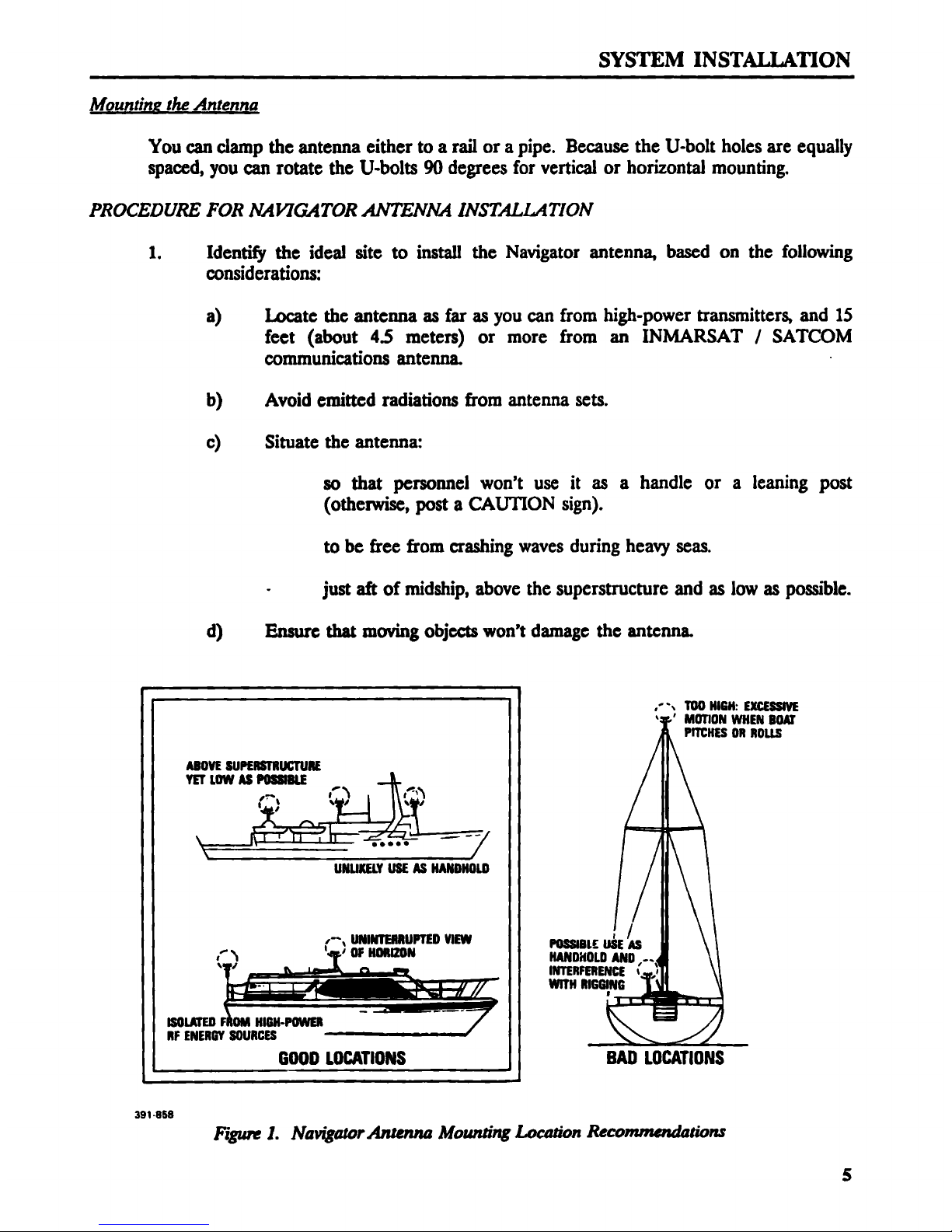
1 Navigator Antenna Mounting Location Recommendations ...................... 5
2 Navigator Vertical/Horizontal Antenna Mounting and Dimensions ................ 6
3 Antenna Connector Assembly ............................................ 7
4 Reference Stn Vertical/Horizontal Antenna Mouning & Dimensions ............... 8
5 Reference Stn Antenna Connector Assembly (TNC) ........................... 9
6 Rear Panel of the DGPS 12 Channel Receiver .............................. 11
7 Installation Template .................................................. 12
8 MULTI-PORT Interface Connector Pin Assignments ......................... 15
9 Magnavox Receiver to PC Interface Connector and Cables ..................... 16
10 Receiver Partially Disassembled ......................................... 19
11 Exploded View of the Receiver .......................................... 23
TABLES
Table hg;
1 System Parts ......................................................... 1
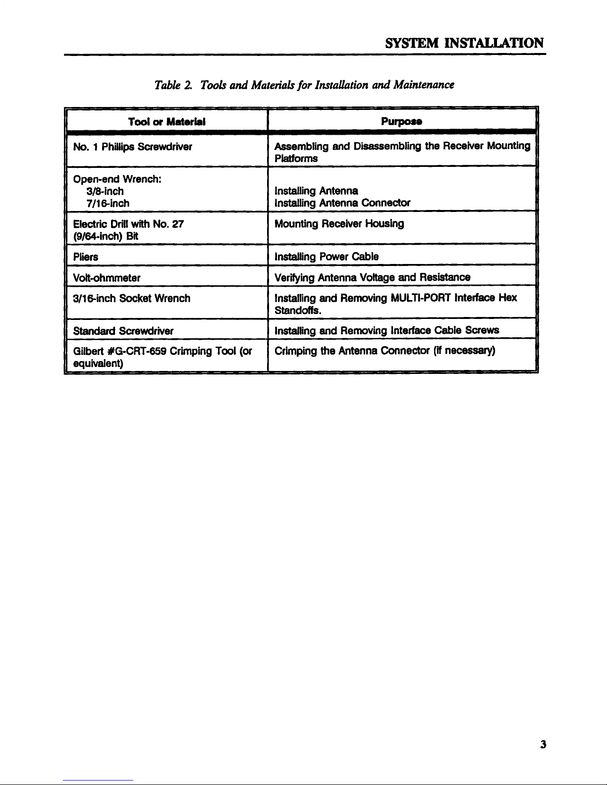
2 Tools and Materials Required for Installation and Maintenance .................. 3
3 Compass Safe Distance ................................................ 10
4 Electrical Interfaces and Data Formats .................................... 14
5 Receiver Parts List ................................................... 22
6 Troubleshooting Table ................................................. 26
iii
Page 6
SYSTEM INSTALLATION
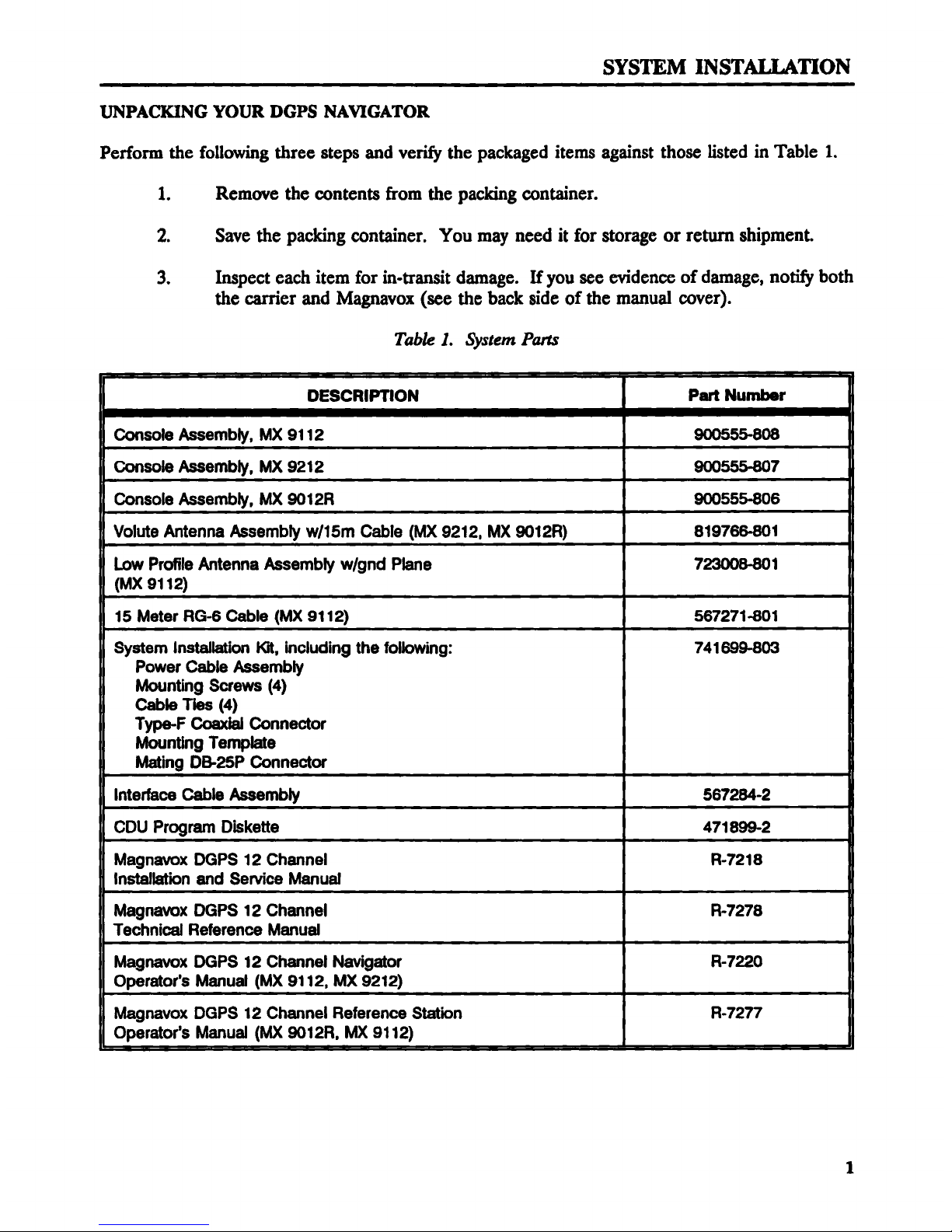
UNPACKING YOUR DGPS NAVIGATOR
Perform the following three steps and verify the packaged items against those listed in Table 1.
1. Remove the contents from the packing container.
2. Save the packing container. You may need it for storage or retum shipment.
3. Inspect each item for in·transit damage. Ifyou see evidence of damage, notify both
the carrier and Magnavox (see the back side of the manual cover).
Table I. System Pans
I DESCRIPTION Part Number 1
1 Console Assembly, MX 9112 900555-808 1
I
1 Console Assembly, MX 9212 900555-807 1
Console Assembly, MX 9012R 900555-806 1
Volute Antenna Assembly w/15m Cable (MX 9212, MX 9012R) 819766-801 1
Low Profile Antenna Assembly w/gnd Plane 723008-801
1 (Mx 9112) 1
15 Meter RG-6 Cable (MX 9112) 567271-801 1
System Installation Kit, including the following: 741699-803
Power Cable Assembly 1
Mounting Screws (4)
Cable Ties (4) 1
Type-F Coaxial Connector
Mounting Template 1
Mating DB-25P Connector
lnterlace Cable Assembly 567284-2 1
CDU Program Diskette 471899-2
Magnavox DGPS 12 Channel R·7218 1
Installation and Service Manual 1
Magnavox DGPS 12 Channel R-7278 1
Technical Reference Manual 1
Magnavox DGPS 12 Channel Navigator R-7220 1
Operator's Manual (MX 9112, MX 9212)
Magnavox DGPS 12 Channel Reference Station R-7277 [
Operator's Manual (MX 9012R, MX 9112) 1
1
Page 7
SYSTEM INSTALLATION
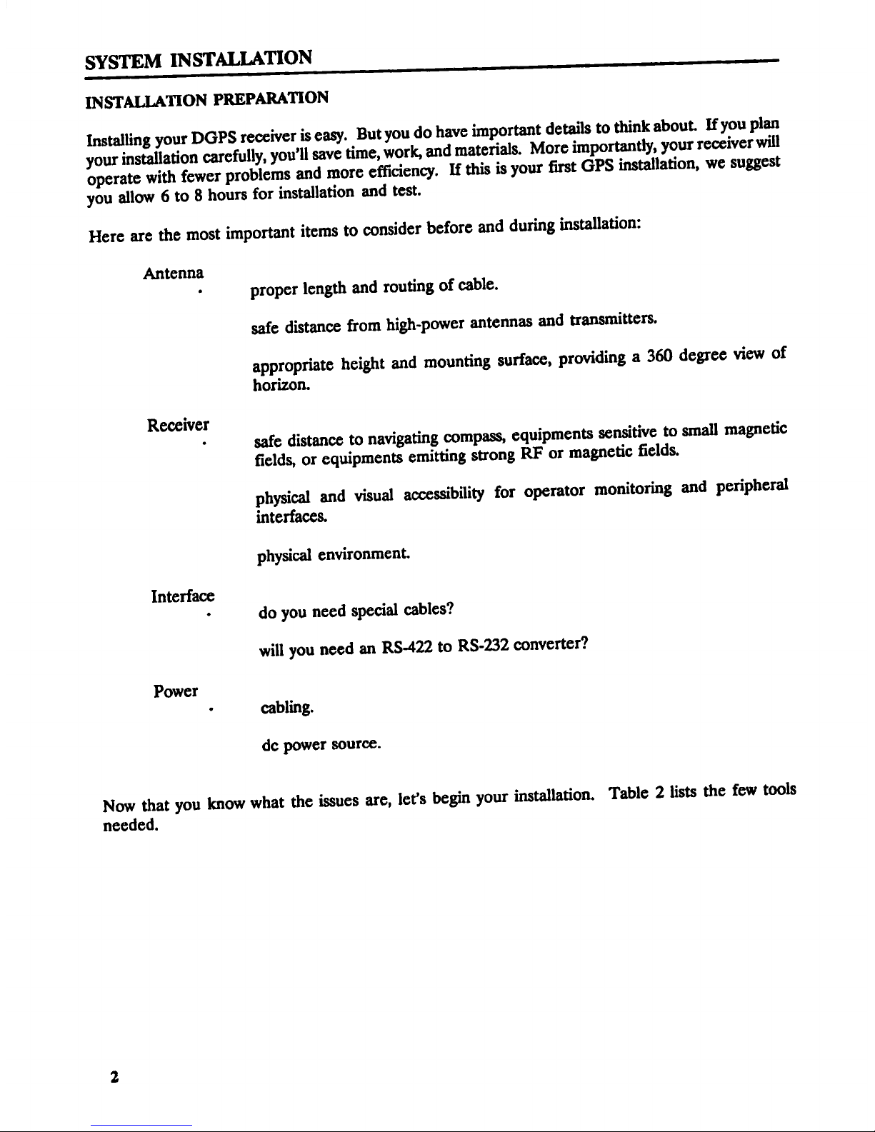
INSTALLATION PREPARATION
Installing your DGPS receiver is easy. But you do have important details to think about. Ifyou plan
your installation carefully, you’ll save time, work, and materials. More importantly, your receiver will
operate with fewer problems and more efficiency. If this is your first GPS installation, we suggest
you allow 6 to 8 hours for installation and test.
Here are the most important items to consider before and during installation:
Antenna
· proper length and routing of cable.
safe distance from high-power antennas and transmitters.
appropriate height and mounting surface, providing a 360 degree view of
horizon.
Receiver
· safe distance to navigating compass, equipments sensitive to small magnetic
fields, or equipments emitting strong RF or magnetic Eelds.
physical and visual accessibility for operator monitoring and peripheral
interfaces.
physical environment.
Interface
• do you need special cables?
will you need an RS-422 to RS-232 converter?
Power
· cabling.
dc power source.
Now that you know what the issues are, let’s begin your installation. Table 2 lists the few tools
needed.
2
Page 8
__0_ _0000 0 _____0___0_ 0 0 0 0_ _0_0 0__ 0_0___ 0_ _0_ _0__0_ ____0___ ___ _ 0 _______0________
r__ _. r__ __ M_ten__ _or I_r_Y_rion D_ M_intenDnc_
_^^__ ^__ _____^__ m_^____ ^__^_^^' ^'^ _^' ______ ^^^ ^ ^ ^ _^^^_
hto. 1 Phillips S48wdiNer _ambling 8nd ___embling th_ Re_N_r Mounting _
P_orms
p8n-end wr8nch:
3__in ch l ns_ling Anten na
7J1 _tn_h Installin9 Ant0n__ Conn0_Y _
Ele_ri_ Drtll Mh No. 27 Mounting Re_her Houstng
(9J_-in_h) B_ _
P_'_rs In_ling Pow_r C_l8 _
V__h_et8r V8r_in9 Antenna Vo_9e and Res__ _
3/1_-_nch m__t wr8nch _n6tal_._ng _d Re_v'_ng muLTl-__ lnt8__ H_ __,
S_ndotM. _
Stand8d S4_wd_N_r In_ling _d R8rnoving Int8___ C_l_ Sy8_ _
_ilbe_ dG-CRT-859 Crimping T_l (or Crtmping m_ _t_nna Conn__Dr (_ n8_) _
8q u N_e nt) ,,
Page 9
SYSTEM INSTALLATION
INSTALLING THE AN'I'ENNA
Installing the antenna is the most crutial part of the system installation. How and where you install
your antenna, with its cabling and integral preamplifier, can greatly affect its sensing efhciency.
Figure 1 shows you both good and bad installation sites for the navigator antenna.
Keep the following guidelines in mind for an ideal site: Try to install the antenna where it has a
clear view of the sky whether on land, sea, or air.
Egsy Access to Maintenance
You want to locate the antenna for easy access and maintenance. Stay safely away from
interfering high-power energy sources like radar and radio antennas. Locate the antenna at
least 9 feet (about 3 meters) away from and out of the transmitting beam of high-power
transmitters.
Avoiding Vertical Obstructions
You should not install the antenna closer than 15 feet (about 4.5 meters) to any large vertical
obstruction. The object is for the antenna to see the horizon freely through 360 degrees and
5 to 90 degrees above the horizon. Be sure that you have the base of the antenna at least
3 feet (about 1 meter) above any large, metallic, horizontal surface.
Note: Small diameter obstructions, such as masts, booms, and kingpins do not seriously
degrade signal reception, but such objects must not eclipse more than a few degrees of any
given bearing.
Cable Lengths
Standard lengths of RG-6/U, 75—ohm, coaxial antenna cable are 50 feet (about 15 meters).
Ifyou need a longer cable length than the installation kit provides, you can extend the cable
up to a total length of 100 feet, with additional RG-6/U coaxial cable connected by an RF
throughline connector (bullet). If you need additional cable, order Magnavox part number
MB0101, 50 Foot Cable Extension Kit. For cable lengths between 100 and 200 feet (30 to
60 meters), an in-line RF amplifier is required. Order Magnavox part number PA6817C,
Cable Line Amplifier (does not include coaxial cable).
Avoiding EMI Eaects
Try to route the coaxial cable between the antenna and the receiver connector directly; direct
paths reduce electromagnetic interference (EMI) effects. When doing this, avoid running
cable close to high-power lines, such as radar or radio-transmitter lines.
If you must cross antenna cables, do so at 90 degrees, so that magnetic fields are not
coupled.
Finally, consider EMI effects related to antenna cable length; longer lengths can increase
EMI effects.
4
Page 10
Page 11
SYSTEM INSTALLATION
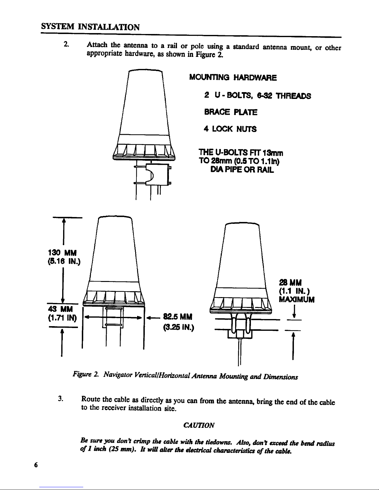
2. Attach the antenna to a rail or pole using a standard antenna mount, or other
appropriate hardware, as shown in Figure 2.
MOUNTING HARDWARE
2 U - BOLTS. 6-32 THREADS
BRACE PLATE
4 LOCK NUTS
THE U-BOLTS FIT 13mm
TO 28mm (0.5 TO 1.1In)
DIA PIPE OR RAIL
130 MM
(5.16 IN.)
28 MM
(1.1 IN.)
MAXIMUM
as uu l
(1.71 IN) <— 82.5 MM . 1
T (3.25 IN.) T
Figure 2. Navigator Vertical/Horizontal Antenna Mounting and Dimensions
3. Route the cable as directly as you can from the antenna, bring the end of the cable
to the receiver installation site.
CAUTYON
Be sure you don? crimp the cable with the tiedowns. Also, don'! exceed the bend radius
of I inch (25 mm). It will alter the electrical characteristics ofthe cable.
6
Page 12
4. Cut the antenna cable to the required length. Leave a little extra length to correct
any mistakes.
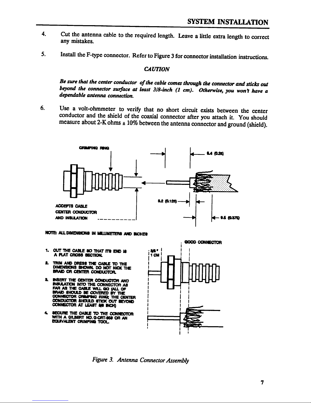
5. Install the F-type connector. Refer to Figure 3 for connector installation instructions.
CAUTION
Be sure that the center conductor ofthe cable comes through the connector and sticks out
beyond the connector surface at least 3/8-inch (1 cm). Otherwise, you won’t have a
dependable antenna connection.
6. Use a volt-ohmmeter to verify that no short circuit exists between the center
conductor and the shield of the coaxial connector after you attach it. You should
measure about 2-K ohms g 10% between the antenna connector and ground (shield).
GQIPIIB HG
{ 4.p{ {4— U (0-25)
‘— “*!
$2 (M8) ‘·P{
A®E"I'8 CABLE
OENTE OONHXZTOR
mo msuumou - ......... °‘° mm
IUTE: ALLDIMBIBIIJS III Il.I.IIlEI'ER8 AID IIOHEU
{ GOOD OGIIECIOR
1. unmeuuwmrmnnm {¤I•'{ { {
A FI.AT GMSS SECTION. I" ca I I
2. TRIM AID DRESS TIE CABLE T0 THE '
DIIEISIQIS SIKIIMI. D0 IDT NICK TIE l
BRAD OR CBGB OOIIJIDTOR.
& INET TIE EGE GOIDUGIOH AND {
N$l.I.A'I'DN INT0 'I'I·IE OGINECTOH A3 I {
FAR AS TIE GAB.! WILL @ (ALL OF I I I
BRAD SIKXID E GNEED BY TIE I I I
GONIEGTOR GFIPIJG RDR THE CENTER
eounucmn annum sncx our mom I I I
eounacmn AT Isur an new { { I
4. OECUE THE CARE TD THE IXIIIEGTOR
WITH A GILBERT ID.G-GRT-|5| OR AN
QIVALBIT ORIMPIII 'I'®I. {
I { I
Figure 3. Antenna ConnectorAssembly
7
Page 13

Page 14

Page 15

INSTALLING THE RECEIVER
Because of its compact size and light weight, you have lots of flexibility in how and where you install
your Magnavox DGPS 12 Channel Receiver. An adjustable mounting platform lets you mount the
unit in any orientation, even on the overhead. To ensure a precise installation, each unit comes with
an installation template.
You will want to choose both a physically safe environment and an eleetromagnetically safe
environment.
Choosing a Safe Physical Environment
Locate an installation site away from excessive heat sources, such as heating vents or
equipment heat exhausts. Also avoid sites (examples would be port holes/windows and
hatches that open to the outside) where the How of humid salt air might corrode intemal
components.
Despite the sturdiness of the Magnavox receiver, don’t subject it to hard, continuous
vibration. If you think excess vibration is a problem, order the vibration isolation kit (P/N:
B19807-801)
Allowing for Progr Distances
Give some thought to the location of the unit. You may wish to visually monitor the three
status indicators (red, yellow and green LEDs, willed traffic lights) on the front panel while
working with other equipment. If you intend to monitor the receiver with a personal
computer, you’ll want to view the screen while at a particular location. A careful choice of
receiver location will minimize cable lengths between components. For Navigators, you’ll
also want to allow a safe distance from the receiver to the navigation compass to minimize
compass deviation. Refer to Table 3 as your guide.
Table 3. Compass Safe Distance
VAT4 (ATT ji_ SWQM _§4l {l
· Posslblo Compass Devlatlon »
I E"""°"`°"'
I
{ Receiver 170 cm (67 in.) 75 cm (30 in.)
M ¤~¤¤ .
Allowing Access to Rear Panel
You will want access to the ANTENNA input connector, the 1 PPS output connector
(perhaps), and the MULTI-PORT Interface DB 25S connector (Figure 4).
Note: The 1 PPS (1 pulse per second) output connector provides an optonal timing source;
the 1·second timing pulses are accompanied by an ASCII message giving you the precise time
of each pulse.
10
Page 16

SYSTEM INSTALLATION
When installing, leave S inches (about 13 centimeters) or more of clearance behind the back
panel of the unit. You will need that much room for dressing the cables and getting at the
rear panel p8ItS.
asn ©··=--·
1PPl
GIITVT
@5,
% © © •¤¤
_lTI·|’$'I’ I|'|'
Figure 6. Rear Panel of the DGPS 12 Channel Receiver
zr and Memory Backug
Your receiver requires a minimum of 10 Vdc and a maximum of 32 Vdc. It requires an
average of 320 milliamps at 15 Vdc (average: 4.8 watts; maximum: 6 watts).
An ON/OFF/REMOTE switch on the back panel determines whether the unit power is
controlled locally or remotely. To control the unit power remotely, you must have the power
switch set to the REMOTE position and be able to apply 5 Vdc to a relay switch in the unit.
Remote power is controlled through the DB 25P connector, pins 1 and 25. Refer to the
wiring diagram, Figure 8.
CMUTION
For relhrble operatibn, you must pmviae dc power to the Magnavox receiver within the 10 to 32
Vdc range. Never apply voltages outswe this range.
The Magnavox receiver power supply does provide over-voltage protection. In addition, an
intemal lithium battery gives you backup power protection for random access memory
(RAM) for up to tive years. Another safeguard is an intemal thermal circuit breaker
protecting the unit from electrical surges (you may have need to reset it; see "Resetting the
Solid State Fuse" under "Maintenance").
11
Page 17

Page 18

SYSTEM INSTALLATION
Connect a ground wire to the GND stud. Connect the ground wire at the other end
to the electrical ground (the user supplies this variable length ground wire not
smaller than 14 Awg.; no more than 1 meter - about 3 feet - in length). This wire
helps disipate EMI signals to reduce interference in the Navigator and other
equipments.
Connect the unit power cable to a dc power source.
CAUTION
Be sure you connect the positive lead ofthe power input cable (identified by the white strip)
to the positive terminal of the dc power supply source. You can verify the polarity of the
cable by checking for continuity between the outer ring of the connector and the negative
(·) power lead.
Connect the antenna cable to the ANTENNA input connector (refer to Figure 6).
13
Page 19

SYSTEM INSTALLATION
CONNECI`ING THE RECEIVER TO EXTERNAL EQUIPMENT
External equipment connects to the MULTI-PORT Interface connector on the rear panel of the
receiver unit (see Figure 6). The interface consists of four Input/Output (I/O) serial ports; two RS-
232 ports and two RS-422 ports. IBM compatible (DOS-based) software controls the
communications. Figure 6 shows you the MULTI-PORT Interface connector pin assignments. If
you are logging data with a personal computer (PC) on one of the two RS-422 ports (2 and 4), you
will need the optional RS-422 to RS-232 data converter kit, P/N 741692-804. You determine the
exact use of the individual I/O ports by your needs and choice of associated equipment. You may,
for example, use the Magnavox Navigator to navigate as a stand-alone unit or as a component in an
integrated system.
Standard Port Uses
Ports 1 and 3 are RS-232 ports; ports 2 and 4 are RS-422 ports. Port 1 is fixed as the Control Port.
All ports are defaulted to 9600 baud. Here are their standard functions:
• Port 1 · RS-232, Operational control and data messages (9600 baud default)
[input/output]
• Port 2 - RS-422, Measurement (Raw data) [output]
• Port 3 - RS-232, DGPS Corrections I/O (MX-SOR) [input for navigators, output for
reference stations]
• Port 4 - RS-422, Equipment/NMEA [input/output]
All ports have selectable baud rates of 300 to 19,200 baud. Table 4 details port functions of both
data and electrical interfaces.
Table 4. Electrical Interfaces and Data Formats
PORT 1 PORT 2 PORT 3 PORT 4
IN RS-232 RS-422 RS-232 RS-422
OUT RS-232 RS-422 RS-232 RS-422
DATA FORMATS
PORT 1 PORT 2 PORT 3 PORT 4
IN CONTROL NOT ACTIVE DGPS I/O NMEA-0183
MESSAGES EQUIPMENT
OUT CONTROL MEASUREMENT DGPS I/O NMEA-0183
MESSAGES RAW DATA EQUIPMENT
14
Page 20

SYS'I`EM INS'I'ALLATION
DB25P CONNECTOR, CONNECTS TO
MULTIPORT INTERFACE CONNECTOR
I "`I
I/ I I
I I
1 I I REM 0N (-> nsmors Pwn
25 V I I REM on (+) 0¤NTR0|-
" I I Pom 1 our
10 RS-232
I 24 I I PORT 1 IN PORT II
I I PORT 1 GROUND
3 { I Pom 2 OUTPUT (+I
1: I I PORT 2 0u1·I=·u1· (-I RS422
I I PORT 2 INPUT (+_ F’¤RT 2
14 I I PORT 2 INPUT (·)
8 I I PORT 3 OUTPUT
I I RS-232
S I I PORT 3 INPUT PORT 3
I I PORT 3 GROUND
5 I I PORT 4 OU'I' PUT (+)
*7 I Pom 4 OUTPUT (-I gs.422
4 I I Pom 4 INPUT (+) P¤F1T 4
16 I I PORT 4 INPUT (-)
I3 I I EXT PWR 12 V (+) POWER OUTPUT
12 I I Ex·r Pvvn mu (60 MA MAX)
2° I I Evarrr INPUT `
21 I I Evzm nsrunu
L- I
GROUND SHIELD ONLY AT
MAGNAVOX END OF CABLE
Figure 8. MULTI-PORT Interface Connector Pin Assignments
15
Page 21

uwonmwm mnscou
P1 P.
W
numnour ' rmamwum ra
m...¤ ==._ mm ¤ ° '“’ ,,,E,,;';;',,f,,"’*"’
P$‘I'1I · · VEDKfA@ ll. Exam.
I`“ ··= — mn °
,,¤.n,.m, Q , _______ QN , _ dl ·nw¤rr¤A·rA(r¤;
,,,,,,,,,_ ,, _______ ·· _ EIIIII ummm
mmam z- ....... T a- Ill? nmuvnmnaq
rumen- s --------
|'0H'I'4l\9·&
.....,.,,. . ________ ._ n ,m,__,_(,,,
PGTATD 1 ________ O __ |npw_ mqp
p@·|*4»•. M 4 ________ 7 4 .. EB£hATA@
,,,,,,,, l'_IH . ________ ¤¤¤¤¤¤•••
EGIEGF
H ~»·~·
•··=w¤ ~ · ~ --—---—- '&¤.»..»—¤.»
EEE -------- ’
EIUIEOIH - 8 —---——-— 28-
umw. · ........ . ·--
PETIOUT · ~· ¤A·rA <—4I|¤$-»I F :·
···"···· I
mmm _ mavnmm mmmm
N, kJ ., umm.
»....··—-.a¤a”$‘·'8¤..¤».» ·=¤·~·¤=··~·¤=··~=
nammesnum ¤$·¤¤¤¤¤
Figure 9. Magnavox Receiver to PC Interface Connector and Cables
16
Page 22

INITIAL POWER-ON CONDITIONS
When you turn on the receiver the PC display unit may indicate "Sats Visible 0, used O" (where the
number of satellites is a number from 1 to 12). Elevation and azimuth values will also be zero.
These are the correct displays until the receiver has acquired an almanac.
After the initial power-up, the receiver begins to collect a new almanac. This process takes 12
uninterrupted minutes of tracking time. This means that the receiver typically requires a total of 15
to 20 minutes, from the time it’s tumed on, to complete its collection of an almanac.
When the almanac has been acquired, the receiver stops tracking satellites briefly, while it conducts
a search of collected data and compiles a table of satellite rise time predictions. The receiver is able
to navigate (or calculate corrections) while making these calculations.
Your receiver will probably have already acquired an almanac. You can verify this by glancing at
the lower right comer of the menu that first appears on the screen. If the number beside "Sats
Visible" is not zero then you already have an almanac. The intemal battery has preserved this
information in memory from the time the unit was shipped from the factory.
If you have an almanac in your receiver, the unit will navigate (or calculate corrections) within 1 or
2 minutes of power up. Because the position shown on the screen maybe in Torrance, California,
the initial displayed positions may be wrong when using a Navigator.
Continue below with TEST PROCEDURE and then refer to one of the "Magnavox DGPS 12
Channel Operator’s Manuals” for a detailed description of the PC CDU program.
17
Page 23

TEST PROCEDURE
When the installation is complete, perform the following steps to ensure proper operation:
1. Turn on the controlling device (Personal computer or other device.)
2. Set the OFF/ON/REMOTE switch (receiver rear panel) to the ON position. If the remote
control option has been implemented set the switch to the REMOTE position and activate
the remote control device.
3. Monitor the trafhc lights (three LED’s on the front panel of the receiver). The normal
startup sequence is as follows:
• RED: Indicates power on.
• YELLOW: Passed self-test, attempting to acquire satellites. (Red light turns off).
• GREEN (flashing): Tracking one or more satellites, but not yet navigating (or
computing corrections). (Yellow light tums off).
• GREEN: Magnavox receiver is navigating (or computing corrections). (No other
lights are on).
During normal operation the receiver cycles between yellow (no tracking), flashing green (some
tracking), and green (navigating/computing corrections). Changes occur as the number and geometry
of tracked satellites vary.
The sequence above is for a receiver that has been tumed on for the first time, or after its memory
has been erased. If your receiver has an almanac, the four items described above may happen so
quickly that some of them may not be noticed.
This concludes the System Installation portion of this manual. If the receiver appears to be
functioning correctly, and if you are using a PC as a Control Display Unit, you will Want to refer to
the additional manual that was shipped with the receiver. See "Magnavox DGPS 12 Channel
Operator’s Manual".
18
Page 24

Page 25

MAINTENANCE
The front panel gets secured to the chassis as it slides into grooves along the front edges of the
plastic cases. Projecting through the front panel are three status indicators. These are red, yellow,
and green LEDs, referred to as ”trafiic lights".
The rear panel is attached to the chassis by one Phillips screw and parts on the two cards; namely,
the Antenna connector on the RF/power supply card and the MULTI-PORT Interface connector
on the processor card.
Additional rear panel parts are:
• ground stud (for chassis grounding)
• power mode switch (OFF/ON/REMOTE switch)
• power socket
• 1PPS output connector, optionally used for system timing.
20
Page 26

REPLACING THE CIRCUIT CARDS
Qisussembly
CMUHON
Magnavox receiver components on the circuit cards are electrostatic discharge (ESD) sensitive.
Take care to dissipate static charges both on the equipment and on your own person. Static
charges can easily destroy the DGPS receiver circuits. lf you’re unaware of ESD safeguards,
please have an authorized service center handle repairs.
For the following procedure, refer to Table 4 and Figure 11. The numbers in parentheses
refer to the part index numbers in Figure 11.
1. Remove the quick-disconnect power cable (8) from the power socket.
2. Disconnect (unthread) the antenna cable from the antenna connector (5).
3. Disconnect the MULTI-PORT Interface cable. Unscrew the `two slotted screws
securing the connector.
4. Remove the four Phillips screws (1) that secure the case to the mounting base. The
screws sit in recesses in the mounting platforms at the sides of the unit.
5. Separate the two halves of the outer casing (2). Be careful. 'I'he unit falls apart as
you separate the two halves of the case. Set the cases, the front EMI shield (10), and
the front panel (16) to the side.
6. Turn the receiver assembly upside down. The three LED’s (15) should then be
closest to the top of the front panel.
7. Remove the two 3/16-inch hex standoff nuts (7) on the sides of the MULTI-PORT
Interface connector (11).
8. Remove the Antenna connector (5) nut and lock washer that secure the RF/power
supply card (4) to the rear panel.
9. Remove the Phillips screw next to the power socket.
10. Set the real panel (9) and the rear EMI shield (10) aside.
Removing the Circuit Cards
1. Remove the 1/4-inch Phillips screw (3) at the center of the processor card (14).
2. Grasp the processor card (14) at the sides with one hand and lift it gently, separating
the header connector (17). Don’t lift it from the front because you might damage
the LED’s.
21
Page 27

MAINTENANCE
3. Tum the assembly over and remove the phillips screw (3) from the center of the
RF/power supply card (4).
4. Grasp the RF/power supply card (4) at the sides with one hand and lift it gently to
separate the circuit card from the molded plastic chassis (6).
Table 5. Receiver Parts List
Figure & Part Number Quantity
Index No. {
1 Housing Screw Ref 4 {
2 Clam Shell Housing Case Ref 2 {
3 Circuit Card Assembly Screw Ref 2
{ 4 RF/Power Supply Circuit 819822-801/802 1 {
{ 5 Antenna Input Connector Ref 1 {
6 Chassis Ret 1
{ 7 Hex Standoff Ref 1 set {
{ 8 Power Cable Assembly Ref 1 {
9 Ftear Panel Ref 1 {
10 EMI Shield Ref 2 j
11 MULTI-PORT Interface Connector Ret 1 {
12 1PPS Connector Ret 1 {
13 Mounting Platform Rei 2 {
14 Processor Circuit Card Assembly 819978-80X 1 ;
{ 15 Light Emitting Diode Ref 3 {
{ 16 Front Panel Ref 1
{ 17 Header, 16 pin Ret 1
Ref. - Refer to parts list for the assembly, of which the item is a part.
22
Page 28

lr/,@
T [I 2 runes
' I. /9
' '“°“
<¤ 2 _ i i~
• I
· "r :
...» . · ’ Hi/mm 1 ~
| ’ II .
» :·=·
{B E · l V ey a>’°:T; —..
', . I ¤ ` caf" '•¤ "
03 " .1 I »' ·. 0 O
{ 4; Q" ,
E QN 2 rb °
REF
I ·\___ 1
I
391-851
Figure 11. Exploded View of the Receiver
Reglacing the Circuit Cards and Re-assembling the Unit
For the following procedure, refer to Table 4 and Figure 11. The numbers in parentheses
refer to the part index numbers in Figure 11.
1. Slide the rear panel (9) and EMI shield (10 into position on the replacement
RF/power supply card (4).
2. Replace the nut and washer on the Antenna input connector (5).
3. Replace the phillips head screw throu the rear anel 9).
P
4. Verify that the header (17) is in place and tirmly seated.
5. Fit the plastic molded chassis (6) onto the RF/power supply card (4). Hold the
chassis (6) in your hand with its recessed side facing the component side of the
RF/power supply card. Grasping the circuit card and the chassis in each hand, bring
them together while tilting the chassis at roughly a 45-degree angle starting at the
23
Page 29

MAINTENANCE
rear panel as you mate the two assemblies. Ease the header pins (17) through the
rectangular opening in the chassis as you join the assemblies.
6. Check to see that the bosses are seated in the comer U·slots of the card.
7. Replace the 1/4·inch screw (3) at the circuit mrd center. Tighten only until snug.
Don’t over tighten.
8. Replace the processor card (14). Grasp the processor card in one hand and hold the
chassis/RF/Power Supply assemblies in the other. Bring them together while tilting
the processor card at roughly a 45·degree angle. Gently ease the two assemblies
together while seeing that the header pins (17) seat properly.
9. Check to see that the bosses are secured in the U-slots at the comers of the card.
10. Replace the 1/4-inch screw (3) at the circuit card center. Tighten only until snug.
Don’t over tighten.
11. Replace the two hex standoffs (7) on the MULTI·PORT Interface Connector.
Tighten only until snug. Don’t over tighten.
12. Set down the receiver and lift up one half of the clam-shell case (2). How you have
the mounting platforms (13) inserted into the clam-shell case must agree with the way
you’re going to mount the receiver (from top or bottom). Be sure you have them
seated the way you want them.
13. Place the front EMI shield (1) and the front panel (16) over the LED’s (15).
14. Hold the front panel (16) with your finger as you lower it and the assembled chassis
down into one side of the clam-shell case (2). Slide the front panel into the grooves
of the case.
15. Install the other half of the clam-shell case (2). Match up the pins on one case with
the receiving holes on the other before joining the two halves of the clam-shell case.
16. Replace the four case·mounting screws (1). Tighten only until snug. Don’t over
tighten.
24
Page 30

MAINTENANCE
RESE'I"l‘ING THE RECEIVER MEMORY
You may occasionally need to reset random access memory (RAM) in the receiver for one of the
following reasons:
You wish to verify that two·way communication is taking place.
You may suspect that RAM is corrupted.
A cold start reset procedure erases the almanac, forcing all software settings to their default values.
There will be a 15 minute delay before complete normal operation resumes, just as when the backup
battery fails or when the circuit cards are separated from the chassis. For this reason, you may wish
to try a warm start, or a tepid start before trying a cold start. Neither the warm start nor the tepid
start will erase the almanac.
PROCEDURE
Follow the initialization steps in the Magnavox DGPS 12 Channel Operator’s Manual to execute the
Magnavox CDU program. Continue with these instructions after communications have been
established between the PC and the receiver.
1. If the Main Menu is not presently displayed press the ESC key. Use the tab key to
highlight the PC Modem Control field.
2. Select the PC MODEM CONTROL Menu with the enter key.
3. Key in the string: $PMVXG,018,* (must be all upper case characters) where "" is
W = Warm Start; saves the old almanac and re-acquires the satellites.
T = Tepid Start; saves the almanac but erases all other parameters.
C = Cold Start; erases the almanac and starts from the beginning. Re-
acquires almanac in about 15 minutes.
25
Page 31

RESETHNG THE SOLID STATE FUSE
'Ihe solid state fuse (thermal circuit breaker) is located in the power input housing on the RF/power
supply CCA. To reset it, remove the power cord from the rear panel receptacle and replace it after
10 seconds. If the problem persists, or recurs repeatedly, remove power from the equipment and
obtain service from your authorized Magnavox dealer.
TROUBLESHOOTING
The receiver traffic lights not only indicate operational status but also can aid you in identifying
common problems. Use Table 6 to identify common problems and remedies.
Table 6. Troubleshooting Table
{ Status Indicators
{ Rad Y now Probable Cause Recommended {
. e
{ _ ._._ _- Em.; _. -_._r,___,_i_ ._ ;{
- Circuit breaker Reset circuit {
{ tripped or no breaker by
{ power to unit. toggling power {
{ switch ON/OFF
{ positions. {
{ OFF Not tracking 1) Check for
{ satellites. proper antenna
{ connection.
{ 2) Verify clear
{ visibility to
skyline. {
{ 3) See below. {
{ OFF OFF FLASHING Tracking satellites 1) if in Search- {
{ but not the·Sky, wait for
{ navigating! additional
{ computing satellites to be
{ corrections. acquired.
{ 2) Check {
operator-entered {
{ elevation limit. {
A 3) Check
operator-entered
DOP limit.
26
Page 32

MAGNAVOX DGPS 12 CHANNEL RECEIVER SPECIFICATIONS
GENERAL OPERATING CHARACTERISTICS
NAVIGATOR OPERATING MODES 3 Dimensional navigation
Altitude hold (3 satellites visible)
Automatic cold start (no time or position
input required)
Altitude aided
POSITION UPDATE RATE: Once per second
TIME TO FIRST FIX: 1 minute (typical), with almanac in memory
ACCURACY: TBD
SELF—TEST COVERAGE: Antenna, antenna cable, digital sections of the
circuit card assemblies, and analog section of
the RF/power supply CCA
REMOTE CONTROL SOURCES: IBM PC with control software, provisions for
remote ON/OFF oontrol.
SIGNAL INPUT A __]
RECEIVER TYPE: Continuous Tracking. L1 frequency, C/A code (
(SPS), 12·channel (Independent) I
RECEIVER SENSlTlVI'I'Y: -143 dBm Costas threshold I
NAVIGATOR ANTENNA TYPE: Volute with integral L1 preamplifier h
NAVIGATOR ANTENNA CABLE:
Impedance 75 OHMS
Maximum Loss Limit 13 Db at L1 I
REFERENCE STN ANTENNA 'I'YPE: Low profile with ground plane {
I REFERENCE STN ANTENNA CABLE:
Impedance 75 OHMS
L Maximum loss Ilmit 13 Db at L1
27
Page 33

APPENDIX A
ELECTRICAL INTERFACES
INPUT:
Port 1 and 3 RS-232
Port 2 and 4 RS-422
OUTPUT:
Port 1 and 3 RS-232
Port 2 and 4 RS·422
BAUD RATE: 300 to 19200 baud all ports, selectable
OUTPUT DATA: Position, speed vector (COG, SOG, Vn, Ve) GPS status, navigation
data, time
DATA FORMATS: NMEA·0183 · proprietary; RTCM 104; ASCII
I PHYSICAL DATA · RECEIVER
DIMENSIONS:
Height 45 millimeters (1.8 inches)
Width 138 millimeters (5.4 inches)
Depth 177 millimeters (7.0 inches)
WEIGHT: 900 grams (2 pounds) _]
PHYSICAL DATA · ANTENNA
DIMENSIONS:
Helght 190 millimeters (7.5 inches) I
Diameter 83 millimeters (3.3 Inches l
WEIGHT (with cable): 1,134 Kilograms (2.5 pounds) l
CABLE LENGTH: 15 meters (50 feet) J
28
Page 34

APPENDIX A
Y ENVIRONMENTAL DATA
l TEMPERATURE RANGE
Operational 1
l Receiver: -20° to +55°C (0° to +130°F) [
I Antenna: ·40° to +70°C (-40° to +160°F) |
Storage }
Receiver: -40° to +85°C (·40° to +185°F) l
i Antenna: ·40° to +85°C (-40° to +185°F) I
i Hurvnomr l
\ Receiver: 95%
i Antenna: 100% ]
r * A · ·· · · Y :#v··· iivém · V TTTTTJ · ·:§· e- ··i
, nowzn DATA 4
AA AAAAA AAA AA A AAAAAAA A A AAA—A A A AAAAAA
i POWER INPUT REQUIREMENTS: 10-32 Vdc. 4.8 watts average, 6 watts maximum
POWER OUTPUT:
(to connected device) 12 Vdc t 10%, 65 milliamps maximum
<=¤¤¤s¤S ¤$¤»¤~¤¤ #¤¤· ¤¤¤¤¤· ¤¤>¤¤¤- A
29
Page 35

HOW ARE WE DOING?
PLEASE
HELP US TO HELP YOU AND OUR O'l`HER
VALUED CUSTOMERS BY
sending us your evaluation of this manual. We need to know such things as:
• Is the manual complete, or do you need more (or less) infomation?
• Can you find the information you need easily?
• Is the information easy to understand, or could we be clearer?
• Are there any errors and, if so, where and what are they?
Be sure to reference the title and identification number of this manual:
Magnavox DGPS 12 Channel
Installation and Service Manual R-7218
and include your name, address and telephone number. We look forward to Ending out how we
can improve our information services.
All of your comments and suggestions become the property of Magnavox.
Please send them to:
Magnavox Electronic Systems Company
West Coast Division
2829 Maricopa Street
Torrance, CA 90503
United States of America
Attn: Navigation & Positioning, Dept. 775
Technical Writing Supervisor
or write your comments on the READER COMMENT SHEET on the next page and mail it to
us.
Page 36

READER COMMENT SHEET
Magnavox DGPS 12 Channel
Installation and Service Manual R-7218 May 1993
Magnavox welcomes your evaluation of this manual. Please note errors, suggest additions, or
make general comments below. Use extra pages if you like. All comments and suggestions
become the property of Magnavox.
Do not use this form to request purchases, maintenance assistance, or additional publications.
Please contact your Magnavox marketing representative for purchases or additional publications,
and your nearest authorized service representative for maintenance assistance.
Thank you.
YOUR NAME:
ADDRESS:
PHONE: ( )
mm on mzokms uns AS su0wN ON ormsn sms 01= PAGE AND sm}. wrm TAPE.
Page 37

Paste
Stamp
Here
MAGNAVOX ELECTRONIC SYSTEMS COMPANY
WEST COAST DIVISION
2829 Maricopa Street
Torrance, CA 90503,
USA
Attn: Navigation & Positioning, Dept. 775
Technical Writing Supervisor
Page 38

. 77 7 77777 7 77 77 77 777 77 7 7 77 77777 7777777 77 7 77777777777777 777 7
Describe Problem (How long have you had this problem and is it Part and Serial No. {
repeatable). {
What is connect to the control port (normally port l)? UTC Time/Date of {
Problem {
{
What is connected to the raw data port (2)? LAT/DON {
Do you have high-power transmitting equipment, such as radar or Indicate GDOP, {
SSB radios? What are the signal strengths of satellites under track? HDOP, and VDOP,
if available. {
1.____ {
2. {
3. {
Are you using Magnavox PC control software for control of Show problem state of {
peripherals? LEDs
Red {
If Yes, what version? {
Green
Yellow {
{ Are you recording the raw data to disk? Have you reset the
{ system?
¢
{ Yes {
{ No {
Did it help? {
{ Yes No
Page 39

Paste
Stamp
Here
Magnavox Electronic Systems Company
West Coast Division
2829 Maricopa Street
Torrance, CA 90503
USA
Attn: Navigation & Positioning, Dept. 775
Technical Writing Supervisor
Page 40

Refer to the "Standard Condition of Sale" on your Order acknowledgement or Invoice.
REQUEST FOR SERVICE
MAGNAVOX IS REPRESENTED BY A WORLDWHJE NETWORK OF SERVICE
REPRESENTATIVES WHO ARE AVAILABLE TO SERVICE TI—IE COMPLETE RANGE
OF MAGNAVOX MARINE AND SURVEY PRODUCTS.
CONTACT MAGNAVOX FOR THE LOCATION OF YOUR NEAREST AUTHORIZED
SERVICE REPRESENTATIVE.
MAGNAVOX ELECTRONIC SYSTEMS COMPANY
WEST COAST DIVISION
2829 Maricopa Street
Torrance, CA 90503
U.S.A.
A’I’I'N: MSSD-FIELD SERVICE MANAGER
PHONE: (310) 320-1555 (24 I-IOUR SERVICE)
OR (310) 618-7026
TELEX: 696101 MAGNA MSO TRNC
FAX: (310) 618-7001
CABLE ADDRESS: MAGNAMAR
YOU WH,L NEED TO KNOW YOUR UNI'T’S MODEL AND SERIAL NUMBER WHEN
CONTACTING MAGNAVOX FOR SERVICE. RECORD THE SERIAL NUMBER BELOW.
YOUR MODEL NUMBER IS:
MX 9212 MX 9112 MX 9012R
SERIAL NUMBER:
 Loading...