

Page 1
MVR440MG/17
MVR450MG/17
MVR650MG/17
Video Cassette Recorder
OWNER’S MANUAL
THANK YOU FOR CHOOSING MAGNAVOX.
N
EED HELP FAST?
READ YOUR QUICK-USE GUIDE AND/OR OWNER’S MANUAL FIRST FOR
QUICK TIPS THAT MAKE USING YOUR
MAGNAVOX PRODUCT MORE ENJOYABLE.
I
F YOU HAVE READ YOUR INSTRUCTIONS AND STILL NEED ASSISTANCE,
YOU MAY ACCESS OUR ONLINE HELP AT WWW.MAGNAVOX.COM
OR CALL
1-800-705-2000 WHILE WITH YOUR PRODUCT.
IMPORTANT!
RETURN YOUR WARRANTY REGISTRATION CARD WITHIN 10 DAYS.
S
EE WHY INSIDE.
Page 2
Once your MAGNAVOX purchase is registered, you’re eligible to receive all the privileges of own-
ing a MAGNAVOX product. So complete and return the Warranty Registration Card enclosed with
your purchase at once. And take advantage of these important benefits.
Return your Warranty Registration card today to
ensure you receive all the
benefits
you’re entitled to.
For Customer Use
Enter below the Serial No.which
is located on the rear of the cabinet.Retain this information for
future reference.
Model No. __________________
Serial No. __________________
Congratulations on your purchase,
and welcome to the “family!”
Dear MAGNAVOX product owner:
Thank you for your confidence in MAGNAVOX.You’ve selected
one of the best-built,best-backed products available today. And
we’ll do everything in our power to keep you happy with your
purchase for many years to come.
As a member of the MAGNAVOX “family,” you’re entitled to
protection by one of the most comprehensive warranties and
outstanding service networks in the industry.
What’s more,your purchase guarantees you’ll receive all the
information and special offers for which you qualify, plus easy
access to accessories from our convenient home shopping
network.
And most importantly you can count on our uncompromising
commitment to your total satisfaction.
All of this is our way of saying welcome-and thanks for investing
in a MAGNAVOX product.
P.S. Remember, to get the most from your
MAGNAVOX product, you must return your
Warranty Registration Card within 10 days. So
please mail it to us right now!
Know these
safetysymbols
This “bolt of lightning” indi-
cates uninsulated material
within your unit may cause an
electrical shock.For the safety of
everyone in your household,
please do not remove product
covering.
The “exclamation point”
calls attention to features
for which you should read
the enclosed literature closely to
prevent operating and maintenance problems.
WARNING: TO PREVENT
FIRE OR SHOCK HAZARD ,DO
NOT EXPOSE THIS EQUIPMENT TO RAIN OR MOISTURE.
CAUTION: To prevent electric
shock, match wide blade of plug
to wide slot,fully insert.
ATTENTION: Pour éviter les
choc électriques, introduire la
lame la plus large de la fiche dans
la borne correspondante de la
prise et pousser jusqu’au fond.
R
E
G
I
S
T
R
A
T
I
O
N
N
E
E
D
E
D
W
I
T
H
I
N
1
0
D
A
Y
S
Hurry!
Warranty
Verification
Registering your product within
10 days confirms your right to
maximum protection under the
terms and conditions of your
MAGNAVOX warranty.
Owner
Confirmation
Your completed Warranty
Registration Card serves as
verification of ownership in the
event of product theft or loss.
Model
Registration
Returning your Warranty
Registration Card right away
guarantees you’ll receive all
the information and special
offers which you qualify for as
the owner of your model.
Visit our World Wide Web Site at http://www.magnavox.com
Page 3
Introduction 3
This manual describes the MVR440MG/17,MVR450MG/17, and
MVR650MG/17. The MVR440MG/17 and MVR450MG/17 have a
single sound channel,but the MVR650MG/17 has stereo sound
(right and left sound channels).Otherwise, these models look and
operate the same.This manual illustrates the MVR650MG/17.
Features
• Automatic Channel Setup
• Automatic Head Cleaner
• Automatic Tracking Adjustment
• Hi-Fi Stereo Sound (MVR650MG/17 only)
• MTS (Multi-Channel Television Sound) (MVR650MG/17 only)
• 19 micron head - Improves the picture quality
• On-Screen Displays in English,French and Spanish
• One-Touch Recording
• Real-Time Counter
• Repeat Play
• Search Functions:Index, Time
• Timer Recording
Package contents
The following items are provided with your new VCR.
• Remote Control and two AA batteries
• One RF coaxial cable, 75 ohm
• This Owner’s manual and Quick-Use Guide
Safety Precautions
Warning:To prevent fire or shock hazard, do not expose
this equipment to rain or moisture.
Federal Communications Commission Warning:Any unauthorized changes or modifications to this equipment void
the user’s authority to operate it.
This VCR has a High Quality (HQ) system and is compatible with
existing Video Home System (VHS) equipment.
Magnavox recommends you use only video cassettes that have the
mark.Using other tapes may result in poor picture quality
and excessive deposits on the video heads,which may not be covered by the warranty if damage occurs.
Note to the Cable TV System Installer: This reminder is provided to call the Cable TV system installer’s attention to Article
820-40 of the National Electrical Code, which provides guidelines
for proper grounding – in particular, specifying that the cable
ground shall be connected to the grounding system of the building,
as close to the point of cable entry as possible.
Declaration of Conformity
Model Numbers: MVR440MG/17,MVR450MG/17,
MVR650MG/17
Trade Name: Magnavox
Responsible Party: Philips Consumer Electronics
P.O.Box 14810
Knoxville, TN 37914-1810
(865) 521-4316
Copyright 2004 Magnavox. All rights reserved.
• Before doing anything else, record the
VCR’s model and serial numbers in
the spaces provided on page two.
These numbers will help us assist you
if you ever call for help.
• Your new product and its packaging
contain materials that can be recycled and reused. Specialized companies can recycle your product to
increase the amount of reusable
materials and to minimize the
amount that needs to be properly disposed.
Your product uses batteries that
should not be thrown away when
depleted but should be disposed of as
small chemical waste.
Please find out about the local regulations on disposal of your old product,
batteries, and packaging whenever
you replace existing equipment.
Helpful Hints
Page 4

4 Table of Contents
Setting Up Your VCR
Introduction . . . . . . . . . . . . . . . . . . . . . . . . . . . . . . . . . . . . . . . . . . . . . . . . . . . . . . . . . .3
Table of Contents . . . . . . . . . . . . . . . . . . . . . . . . . . . . . . . . . . . . . . . . . . . . . . . . . . . . . .4
Before Using Your VCR . . . . . . . . . . . . . . . . . . . . . . . . . . . . . . . . . . . . . . . . . . . . . . . . . .5
Hookups:No Cable Box/Satellite . . . . . . . . . . . . . . . . . . . . . . . . . . . . . . . . . . . . . . . . .6-7
Hookups with Cable Box/Satellite . . . . . . . . . . . . . . . . . . . . . . . . . . . . . . . . . . . . . . . .8-9
Hookups with a Stereo TV . . . . . . . . . . . . . . . . . . . . . . . . . . . . . . . . . . . . . . . . . . . . . .10
Turning on Your VCR . . . . . . . . . . . . . . . . . . . . . . . . . . . . . . . . . . . . . . . . . . . . . . . . . . .11
Automatic Channel Setup . . . . . . . . . . . . . . . . . . . . . . . . . . . . . . . . . . . . . . . . . . . .12-13
Setting the Clock . . . . . . . . . . . . . . . . . . . . . . . . . . . . . . . . . . . . . . . . . . . . . . . . . . .14-15
Language Selection . . . . . . . . . . . . . . . . . . . . . . . . . . . . . . . . . . . . . . . . . . . . . . . . . . . .16
Description of Controls
On-Screen Status Displays . . . . . . . . . . . . . . . . . . . . . . . . . . . . . . . . . . . . . . . . . . . . . . .17
Remote Control . . . . . . . . . . . . . . . . . . . . . . . . . . . . . . . . . . . . . . . . . . . . . . . . . . . .18-19
Display Panel . . . . . . . . . . . . . . . . . . . . . . . . . . . . . . . . . . . . . . . . . . . . . . . . . . . . . . . . . 20
Front Panel . . . . . . . . . . . . . . . . . . . . . . . . . . . . . . . . . . . . . . . . . . . . . . . . . . . . . . . . . .21
Rear Panel . . . . . . . . . . . . . . . . . . . . . . . . . . . . . . . . . . . . . . . . . . . . . . . . . . . . . . . . . . .22
Basic Operations
Playing . . . . . . . . . . . . . . . . . . . . . . . . . . . . . . . . . . . . . . . . . . . . . . . . . . . . . . . . . . . . . .23
Recording . . . . . . . . . . . . . . . . . . . . . . . . . . . . . . . . . . . . . . . . . . . . . . . . . . . . . . . . . . .24
Recording
One-Touch Recording . . . . . . . . . . . . . . . . . . . . . . . . . . . . . . . . . . . . . . . . . . . . . . . . . .25
Timer Recording . . . . . . . . . . . . . . . . . . . . . . . . . . . . . . . . . . . . . . . . . . . . . . . . . . .26-30
Recording One Channel/Watching Another . . . . . . . . . . . . . . . . . . . . . . . . . . . . . . . . .31
Rerecording (Tape Duplication) . . . . . . . . . . . . . . . . . . . . . . . . . . . . . . . . . . . . . . . . . . .32
Playing
Repeat Play . . . . . . . . . . . . . . . . . . . . . . . . . . . . . . . . . . . . . . . . . . . . . . . . . . . . . . . . . .33
Special Effects Playback . . . . . . . . . . . . . . . . . . . . . . . . . . . . . . . . . . . . . . . . . . . . . . . . .34
Real-Time Counter Memory . . . . . . . . . . . . . . . . . . . . . . . . . . . . . . . . . . . . . . . . . . . . .35
Time Search . . . . . . . . . . . . . . . . . . . . . . . . . . . . . . . . . . . . . . . . . . . . . . . . . . . . . . . . .36
Index Search . . . . . . . . . . . . . . . . . . . . . . . . . . . . . . . . . . . . . . . . . . . . . . . . . . . . . . . .37
Automatic Playback Features . . . . . . . . . . . . . . . . . . . . . . . . . . . . . . . . . . . . . . . . . . . . .38
Additional Features
MTS Broadcast Stereo (MVR650MG/17) . . . . . . . . . . . . . . . . . . . . . . . . . . . . . . . . .39-40
Hi-Fi Stereo (MVR650MG/17) . . . . . . . . . . . . . . . . . . . . . . . . . . . . . . . . . . . . . . . . . . . .41
Information You May Need
Helpful Hints . . . . . . . . . . . . . . . . . . . . . . . . . . . . . . . . . . . . . . . . . . . . . . . . . . . . . .42-43
Glossary . . . . . . . . . . . . . . . . . . . . . . . . . . . . . . . . . . . . . . . . . . . . . . . . . . . . . . . . . . . .44
Specifications . . . . . . . . . . . . . . . . . . . . . . . . . . . . . . . . . . . . . . . . . . . . . . . . . . . . . . . . .45
Limited Warranty . . . . . . . . . . . . . . . . . . . . . . . . . . . . . . . . . . . . . . . . . . . . . . . . . . . . .46
Index . . . . . . . . . . . . . . . . . . . . . . . . . . . . . . . . . . . . . . . . . . . . . . . . . . . . . . . . . . . . . . .47
Page 5
Before Using Your VCR 5
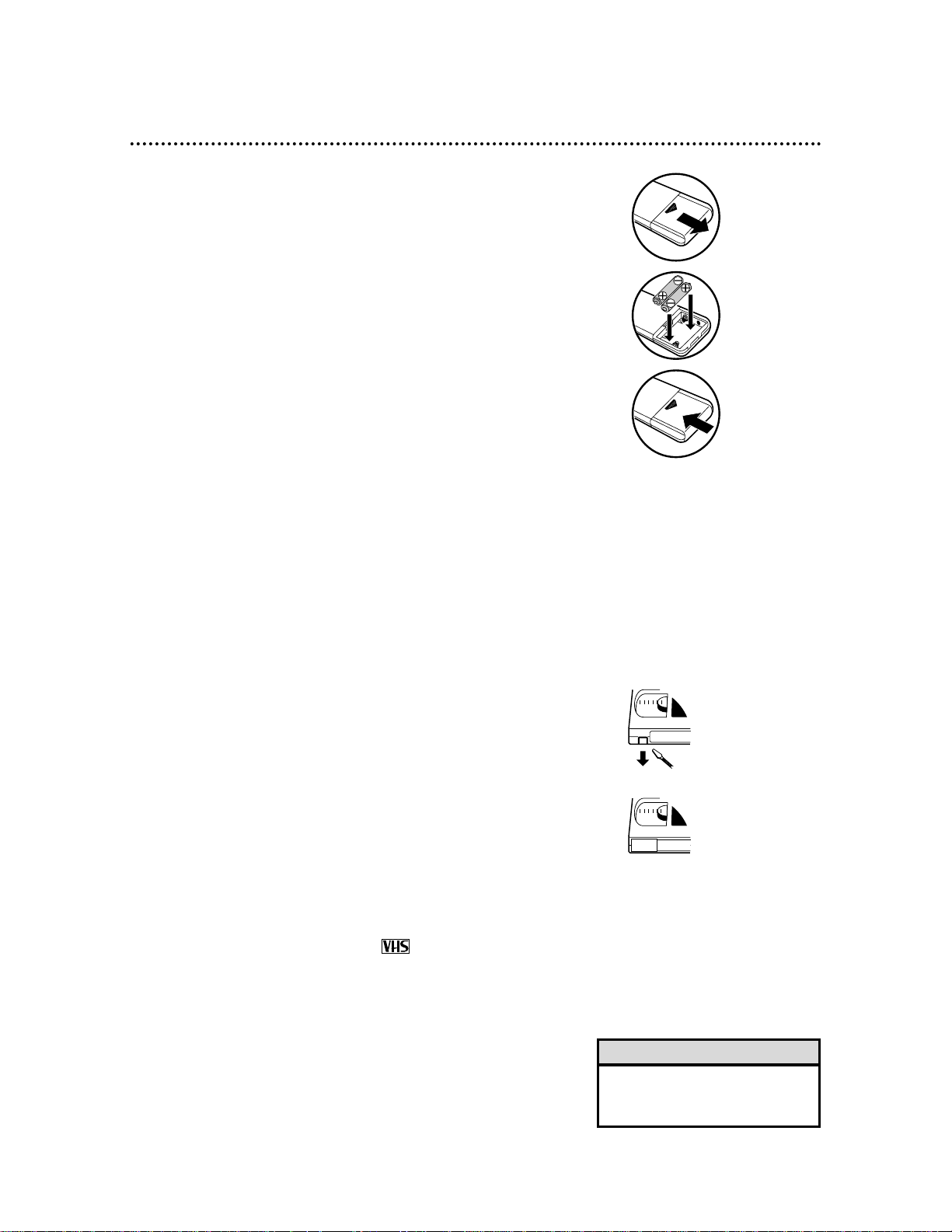
Putting Batteries in the Remote Control
VCR maintenance
● In this VCR, use only tapes with the mark.
● Make sure any light adhesive stick-on notes are removed from
the videotape before putting the tape in the VCR. Removable
labels can jam the VCR.
● Periodic maintenance is required to maintain your VCR’s excellent
performance. This VCR has a built-in Automatic Head Cleaner.
However, the video heads will require replacement eventually. Only
an authorized service center should perform this service .
Using the Remote Control
● Point the remote at the VCR’s remote sensor (see page 21) when
using the remote to operate the VCR.
● Do not put objects between the remote and the VCR.
Recording Prevention
Videotapes have record tabs to ensure that recordings are not
erased accidentally.
1
To prevent recording,break off the tab with a screwdriver.
2
To allow recording,cover the hole with cellophane tape.
• Do not mix alkaline and manganese batteries.
• Do not mix old and new batteries.
Helpful Hints
1
3
2
1
2
1
Remove the battery compartment lid on the bottom of
the remote by sliding the lid in the direction of the arrow.
2
Insert two AA batteries inside the battery compar tment
with their +and – ends aligned as indicated.
3
Replace the battery compartment lid.
Page 6
ANT
AUDIO
VIDEO
IN
OUT
OUT IN
OUT
L
R
IN
AUDIO
R
L
VIDEO
OUT
IN
IN
OUT
OUT
IN
ANT
OR
75
ANT /
CABLE
OR
75
ANT /
CABLE
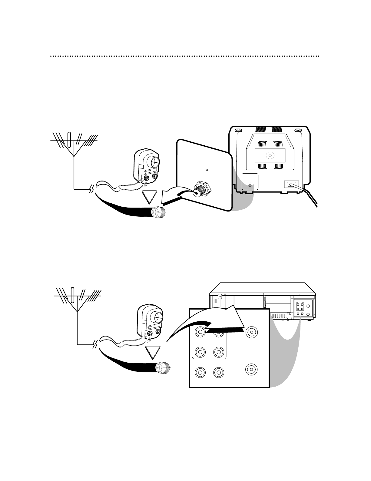
6 Hookups: No Cable Box/Satellite
The basic VCR/TV connection – antenna/Cable TV signal to VCR to TV – is shown below. If you
have a Cable Box or Satellite Receiver, see pages eight-nine. If you have a Stereo TV, see page
10. After you hook up the VCR, go to page 11 to turn on the VCR.
(The MVR650MG/17 is illustrated here. The MVR440MG/17 and MVR450MG/17 have single AUDIO
IN/OUT jacks.)
ANTENNA IN Jack
(on back of TV)
Antenna or Cable TV signal
(75 ohm)
Antenna
Indoor/Outdoor
(300 ohm)
Antenna or Cable TV signal
(75 ohm)
Antenna
Indoor/Outdoor
(300 ohm)
1
Disconnect the antenna or Cable TV signal from your TV.
2
Connect the antenna or Cable TV signal to the ANT(enna) IN Jack of your VCR.
Back of VCR
Page 7
ANT
AUDIO
VIDEO
IN
OUT
OUT IN
OUT
L
R
IN
7
5
A
N
T
/
C
A
B
L
E
AUDIO
R
L
VIDEO
OUT
IN
IN
OUT
OUT
IN
ANT
75
ANT /
CABLE
RF coaxial cable
Antenna or
Cable TV
signal
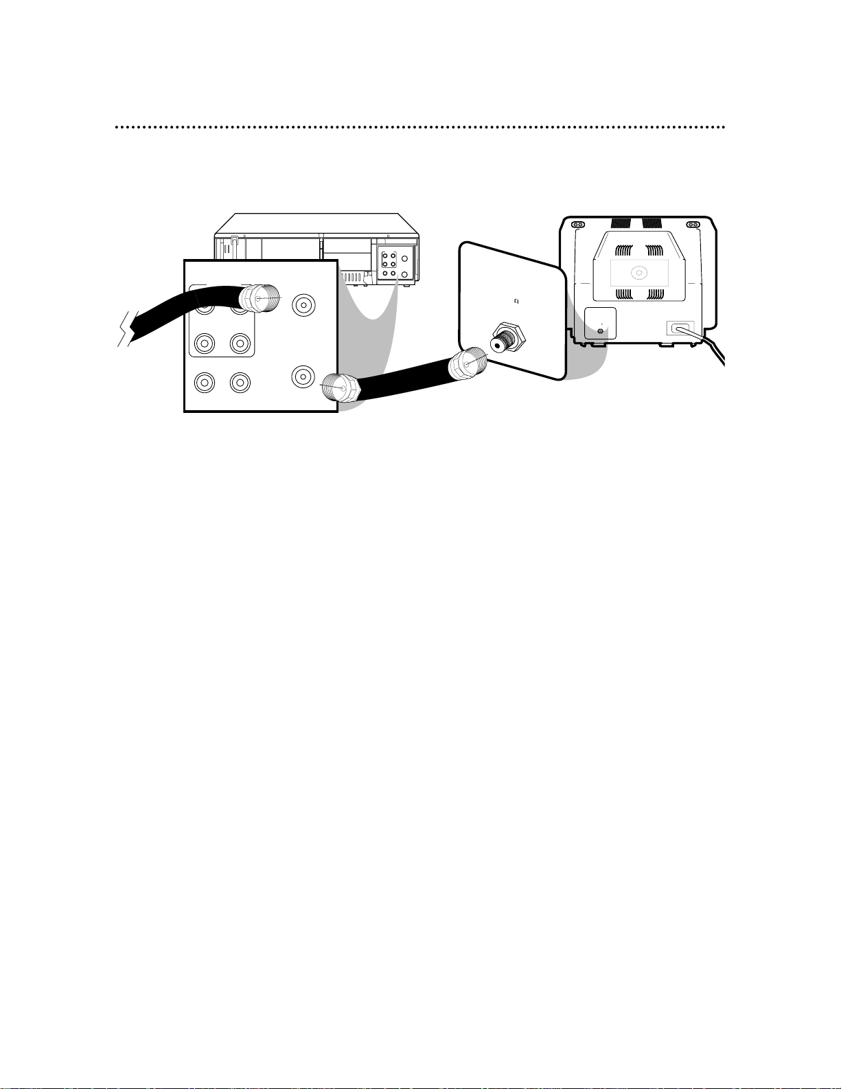
Hookups: No Cable Box/Satellite (cont’d) 7
ANTENNA IN Jack
(on back of TV)
example only
3
Connect the RF coaxial cable (supplied) to the OUT Jack on the back of the VCR and to
the Antenna In jack on the TV. (You may use either a snap-on type (supplied) or screw-on type,
whichever you prefer.)
4
Plug in the AC power cords of the TV and the VCR.
5
Set the TV to channel 3. This is the VCR’s preset RF output channel.
If you cannot use channel 3 at your TV,use channel 4 instead. To change the VCR’s output channel to
4,press and hold PLAY on the VCR for three seconds during tape play. The VCR’s RF output channel
will alternate between 3 and 4 each time you do this. There is not a channel 3/4 switch on the VCR.
You must change the RF output channel as described.
● If the RF output channel does not change , stop tape play,then star t play again. Try again to press
and hold PLAY on the front of the VCR for three seconds during tape play.
● If the power fails or if you unplug the VCR’s power cord for more than 30 seconds,the RF output
channel will return to channel 3.
6
You are ready to turn on the VCR. Please go to page 11 for directions before turning on
the VCR.
Page 8
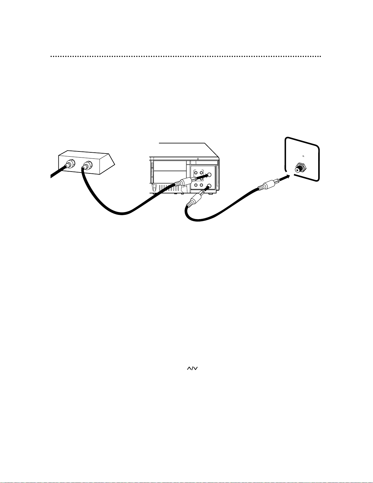
8 Hookups with Cable Box/Satellite
There are two ways to connect your Cable Box/Satellite to the VCR.With this connection:
● You may view any channel.Select channels at the Cable Box/Satellite,not at the VCR.
● You may not view a channel other than the one you are recording.
● Do not set up channels at the VCR.
● Program a timer recording for one channel at a time.Set the TV and the VCR to the Cable Box/Satellite
output channel (03 or 04);set the RF output channel of the VCR to the same channel (see page seven).Set
your Cable Box/Satellite to the channel you want to record. When you enter the channel you want to
record in a timer recording, enter 03 or 04 (the Cable Box/Satellite output channel). (This is step 7 on page
28.) Leave the Cable Box/Satellite on for a timer recording.
ANT
AUDIO
VIDEO
IN
OUT
OUT IN
OUT
L
R
IN
OUT
IN
75
ANT /
CABLE
TV’s
ANTENNA IN
Jack
Cable Box/Satellite
VCR
Connections
1
Connect a Cable TV or Satellite signal to the IN Jack on the
Cable Box/Satellite.
2
Use an RF coaxial cable (supplied) to connect the OUT Jack
on the Cable Box/Satellite to the ANT(enna) IN Jack on the
VCR.
3
Use a second RF coaxial cable to connect the OUT Jack on
the VCR to the TV’s ANTENNA IN jack.
Recording/Viewing Any Channel
1
With the VCR on and in VCR position (the green VCR/TV
light will appear on the display panel),use CH to set
the VCR to the Cable Box/Satellite output channel
(03 or 04).
2
Set the VCR’s RF output channel to 3 or 4. The default
setting is channel 3.See page seven. Set the TV to the
same channel.
3
Select the channel you want to view/record at the
Cable Box/Satellite.
1
2
3
Cable TV or
Satellite
Signal
RF coaxial
cable
RF coaxial
cable
Page 9

Hookups with Cable Box/Satellite (cont’d) 9
ANT
AUDIO
VIDEO
IN
OUT
OUT IN
OUT
L
R
IN
IN
OUT
75
A
N
T
/
C
A
B
LE
With this connection:
● You may watch one channel while recording another.
● You may not record scrambled channels.
TV’sANTENNA
IN Jack
Cable Box/Satellite
VCR
• When you play a tape, set the
Cable Box/Satellite to the same
channel as the RF output channel
of the VCR. (See page seven.) Set
the TV to the Cable Box/Satellite
output channel (03 or 04).
Helpful Hint
1
2
3
Cable TV or
Satellite
Signal
RF coaxial
cable
RF coaxial
cable
Connections
1
Connect a Cable TV or Satellite signal to the VCR’s
ANT(enna) IN Jack.
2
Use an RF coaxial cable (supplied) to connect the OUT Jack
on the VCR to the IN Jack on the Cable Box/Satellite.
3
Use a second RF coaxial cable to connect the OUT Jack on
the Cable Box/Satellite to the ANTENNA IN Jack on the TV.
Recording One Channel/Watching Another
1
Put the Cable Box/Satellite on the same channel as
the VCR’s RF output channel. The default is channel 3.
See page seven.
Set the TV to the Cable Box/Satellite output channel (03 or
04).
Then, with the VCR in VCR position (the green
VCR/TV light will appear on the display panel), use
CH to select the channel you want to record
at the VCR. Start the recording.
2
Press VCR/TV once to put the VCR in TV position.
(The VCR/TV light will disappear.)
3
Select the channel you want to watch at the Cable
Box/Satellite.
Page 10
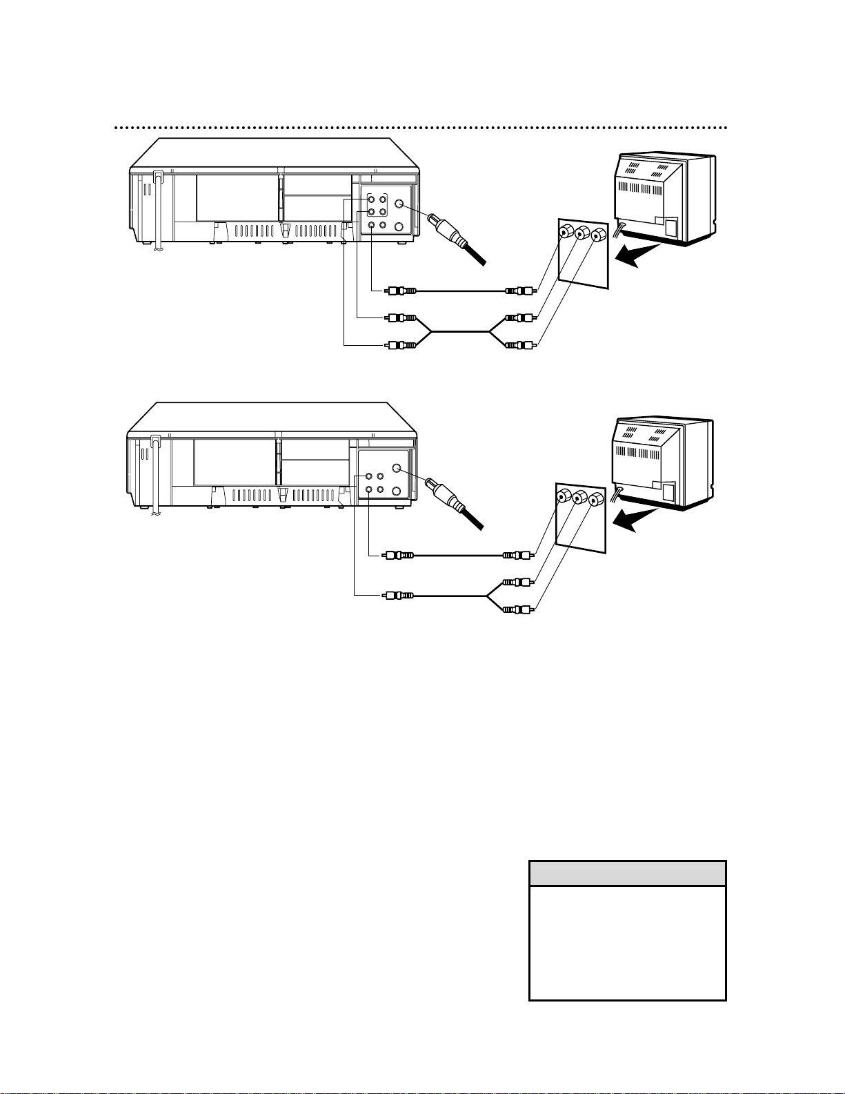
10 Hookups with a Stereo TV
ANT
AUDIO
VIDEO
IN
OUT
OUT IN
OUT
L
R
IN
Antenna or Cable TV signal
to ANT(enna) IN Jack
Video Cable
Audio Cable
VIDEO (yellow) and AUDIO
(red and white) OUT Jacks
Audio and Video
IN Jacks on TV
● Audio and Video cables are not supplied.
1
2
3
• If your TV has only one AUDIO
IN jack, connect a single audio
cable to the white AUDIO OUT
jack on the VCR and to the white
AUDIO IN jack on the TV. See
your TV manual for details of
connecting a VCR to the TV.
Helpful Hint
1
Connect the antenna or Cable TV signal to the
ANT(enna) IN Jack on the back of the VCR.
2
Connect a video cable to the VCR’s yellow VIDEO
OUT Jack and to the TV’s VIDEO IN Jack.
3
MVR650MG/17
Connect a stereo audio cable to the VCR’s red and
white AUDIO OUT Jacks and to the TV’s AUDIO IN
Jacks. Match cable colors to jack colors.
MVR440MG/17, MVR450MG/17
Connect a “Y” splitter audio cable to the VCR’s
white AUDIO OUT Jack and to the TV’s AUDIO IN
Jacks.
4
Turn on your TV, making sure it is in Line Input or
Auxiliary mode.Your TV may refer to this as an Audio/Video
In channel,or A/V In,External In, Auxiliar y In, etc. Such channels are usually located near channel zero (0).Or,your TV
remote may have a button or switch that selects different
Video or Auxiliar y channels. See your TV manual for details.
ANT
AUDIO
VIDEO
IN
OUT
OUT IN
Antenna or Cable TV signal
to ANT(enna) IN Jack
Video Cable
Audio Cable
VIDEO (yellow) and
AUDIO (white) OUT Jacks
Audio and Video
IN Jacks on TV
1
2
3
MVR650MG/17
MVR440MG/17, MVR450MG/17
Page 11
CH
321
654
987
0
POWER
STATUS
SLOWREC MEMORY
SPEED
SEARCH MODE STILL/PAUSE
VCR/TV EJECT
M
EN
U
CLEAR
REW
PLAY
STOP
F.FWD
Turning on Your VCR 11
●Before turning on your VCR, make sure batteries are in the
remote and the VCR and TV are connected (see pages 5-10).
●You cannot set up channels if you are using a Cable Box/Satellite.
●The instructions on this page only work when you turn on the
VCR for the first time. If there is a power failure or if the VCR is
unplugged for more than 30 seconds,repeat this procedure.
1
Press POWER. The POWER light and the VCR/TV light
will appear.
2
Turn on the TV. Set it to the same channel as the RF
output channel of the VCR (see page seven). If you
connected the VCR to a TV using Audio/Video cables, choose
the A/V In or Auxiliary In or Line Input channel at the TV.The
menu shown below will appear.
2
1
Turn on the TV.
• If you do not see any displays
when you turn on the VCR, check
your hookups, then try again. If
you still do not see any displays,
follow the steps under “Automatic
Channel Setup” on page 12 and
“Language Selection” on page 16.
• If you try to set up channels when
there is no antenna or cable connected to the VCR, programming
will appear to take place.
Eventually,AUTO SET UP will
appear on the screen steadily, and
channel programming will stop.
Connect an antenna or cable to
the ANT(enna) IN jack of the VCR,
then press F.FWD again. Channel
programming will begin again.
• To stop channel setup, press
CLEAR.
Helpful Hints
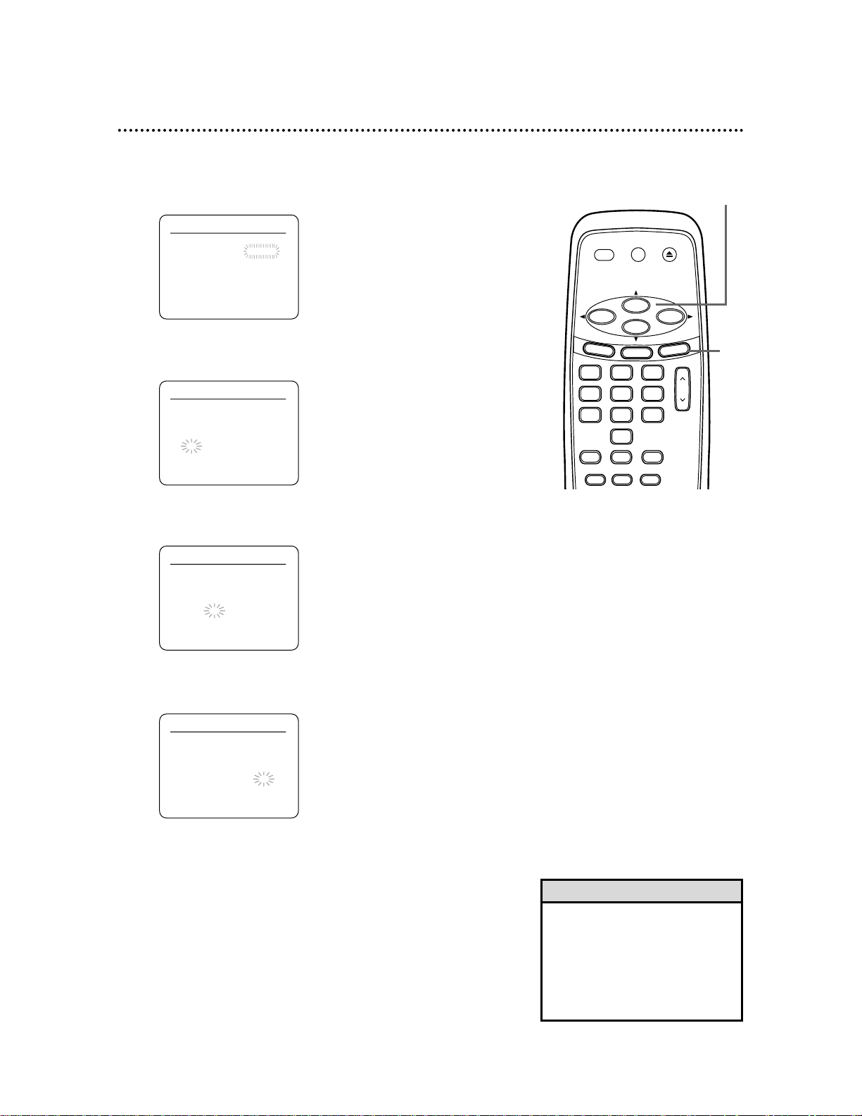
3-5
LANGUAGE SELECT
B ENGLISH [ON]
FRANCAIS
ESPAÑOL
PUSH F.FWD
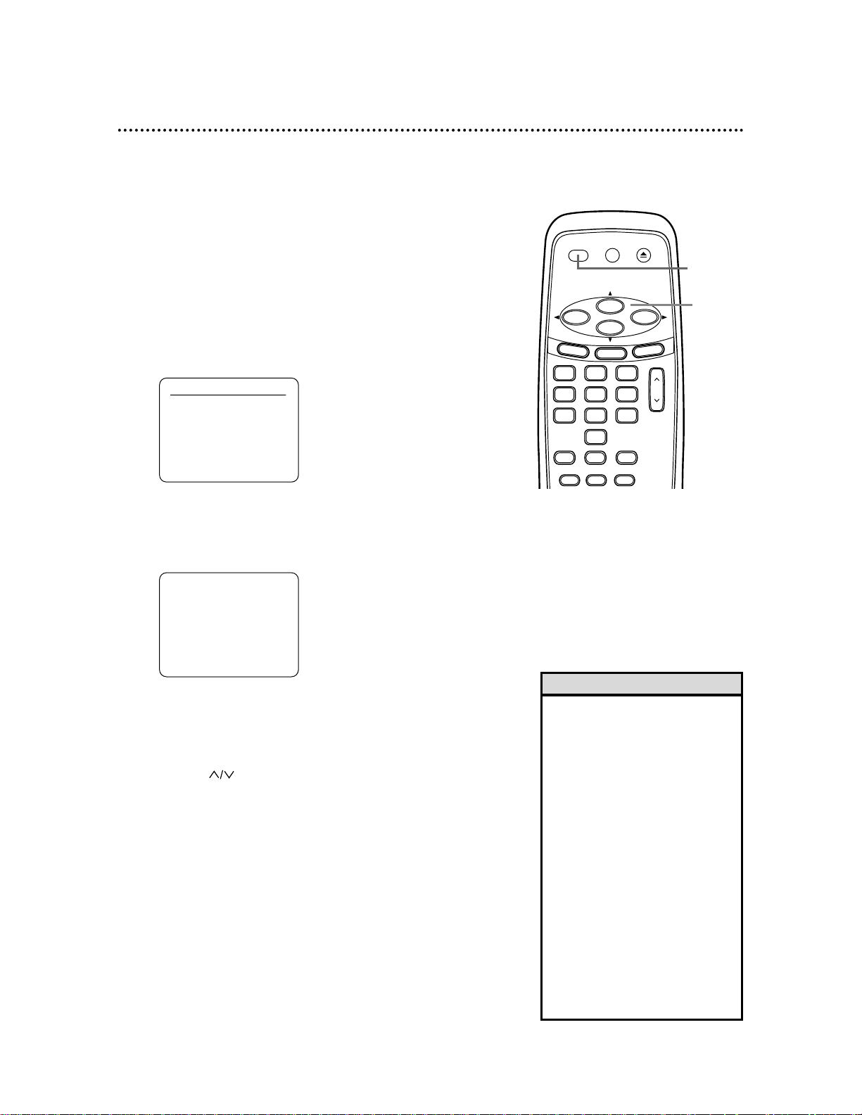
3
Press PLAY or STOP to select ENGLISH, FRANCAIS
or ESPAÑOL. [ON] will appear beside your choice.
4
Press F.FWD. AUTO SET UP will appear on the screen.
5
Press F.FWD to begin automatic channel setup.
AUTO SET UP will flash on the screen and channels will
count up on the screen as setup progresses.When channels
are set up,the VCR will go to the lowest channel available.
The VCR will memorize all available channels,so when you
use CH to change TV channels at the VCR, you’ll only
scan through channels you receive.
AUTO SET UP
PUSH F.FWD
Page 12
12 Automatic Channel Setup
Although your VCR may set channels when you turn it on the first
time, you may set up channels again.Make sure:
●The VCR is on and is in VCR position. (The VCR/TV light will
appear on the display panel.If it does not,press VCR/TV once .)
●Your antenna or Cable TV signal is connected to the VCR. See
pages six-10.
1
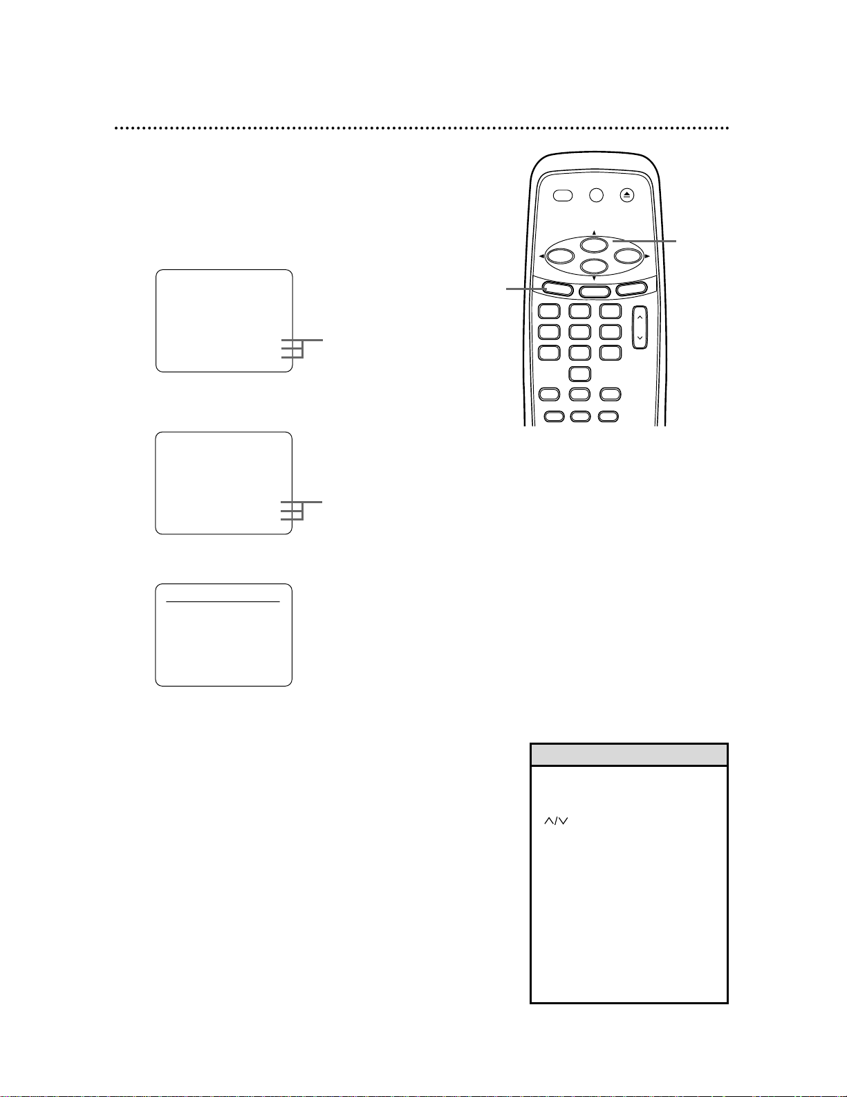
Press MENU until MENU appears.
•
Line Input mode is always channel
001 or 002. Select these channels
with the Number buttons or CH
. Choose L1 if you connect-
ed other equipment to
the AUDIO
and VIDEO IN jacks on the back
of the VCR. Choose L2 if you connected other equipment to the
AUDIO and VIDEO In jacks on
front of the VCR.
• You cannot program channels if
you are using a Cable
Box/Satellite. See pages eight-nine.
• To stop channel setup, press
CLEAR.
Helpful Hints
- M E N U -
TIMER PROGRAMMING
AUTO REPEAT [OFF]
B CHANNEL SET UP
CLOCK SET
LANGUAGE SELECT
AUDIO OUT
TV STEREO [ON]
SAP
- M E N U -
B TIMER PROGRAMMING
AUTO REPEAT [OFF]
CHANNEL SET UP
CLOCK SET
LANGUAGE SELECT
AUDIO OUT
TV STEREO [ON]
SAP
2
Press PLAY or STOP repeatedly to select CHANNEL
SET UP. Press F.FWD.
3
Press PLAY or STOP repeatedly to select AUTO SET
UP.
4
Press F.FWD. The VCR will memorize all available channels.
AUTO SET UP will flash and channels will count up as setup
progresses.When setup is complete, the lowest channel you
receive will appear on the TV screen.
MVR650MG/17 only
MVR650MG/17 only
CH
321
654
987
0
POWER
STATUS
SLOWREC MEMORY
SPEED
SEARCH MODE STILL/PAUSE
VCR/TV EJECT
M
EN
U
CLEAR
REW
PLAY
STOP
F.FWD
1
2-4
CHANNEL SET UP
B AUTO SET UP
MANUAL SET UP
Page 13
CH
321
654
987
0
POWER
STATUS
SLOWREC MEMORY
SPEED
SEARCH MODE STILL/PAUSE
VCR/TV EJECT
M
EN
U
CLEAR
REW
PLAY
STOP
F.FWD
Automatic Channel Setup (cont’d) 13
2-5
• To add or delete more than one
channel, repeat steps 4-5 for all
the channels.Then press CLEAR
to save all the settings.
Helpful Hint
Adding/Deleting Channels
Delete channels you no longer receive or seldom watch from the
memory. Or,add new channels.Make sure:
●The VCR is on and in VCR position. (The VCR/TV light will
appear. If it does not, press VCR/TV once.)
1
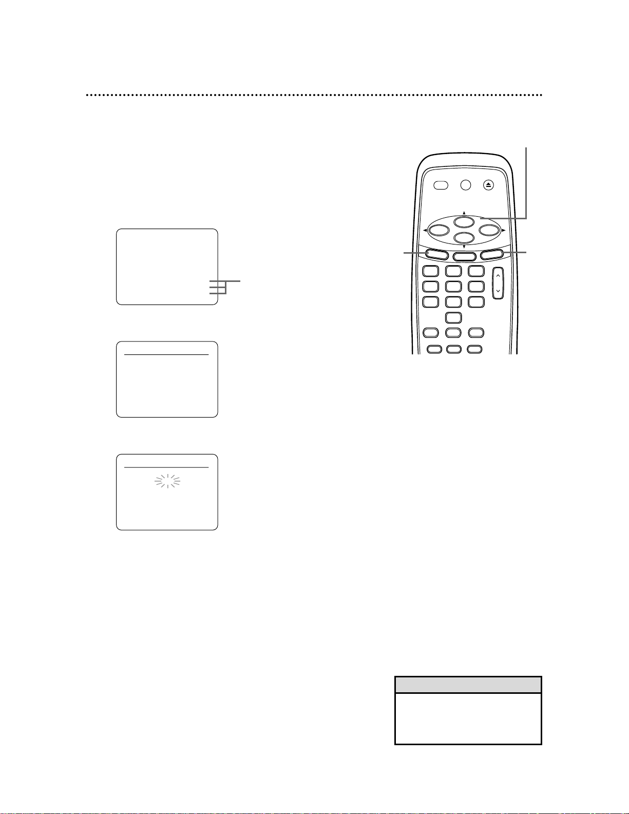
Press MENU until MENU appears.
2
Press PLAY or STOP repeatedly to select CHANNEL SET UP. Press F.FWD.
1
6
CHANNEL SET UP
AUTO SET UP
B MANUAL SET UP
MANUAL SET UP
CHANNEL 30 (CATV)
ADD
- M E N U -
TIMER PROGRAMMING
AUTO REPEAT [OFF]
B CHANNEL SET UP
CLOCK SET
LANGUAGE SELECT
AUDIO OUT
TV STEREO [ON]
SAP
3
Press PLAY or STOP repeatedly to select MANUAL
SET UP. Press F.FWD.
4
Press PLAY or STOP repeatedly until your desired
channel number appears.
5
Press F.FWD or REW so ADD or DELETE flashes on
the screen.
6
While your choice is flashing, press CLEAR. The chan-
nel you added or deleted will appear. The channel will be
added or deleted,whichever was flashing on the screen when
you exited the menu.
MVR650MG/17 only
Page 14
CH
321
654
987
0
POWER
STATUS
SLOWREC MEMORY
SPEED
SEARCH MODE STILL/PAUSE
VCR/TV EJECT
M
EN
U
CLEAR
REW
PLAY
STOP
F.FWD
14 Setting the Clock
Follow the steps below to set your VCR’s clock. Make sure:
● The VCR is on and in VCR position. (The VCR/TV light will appear.
If it does not,press VCR/TV once.)
1
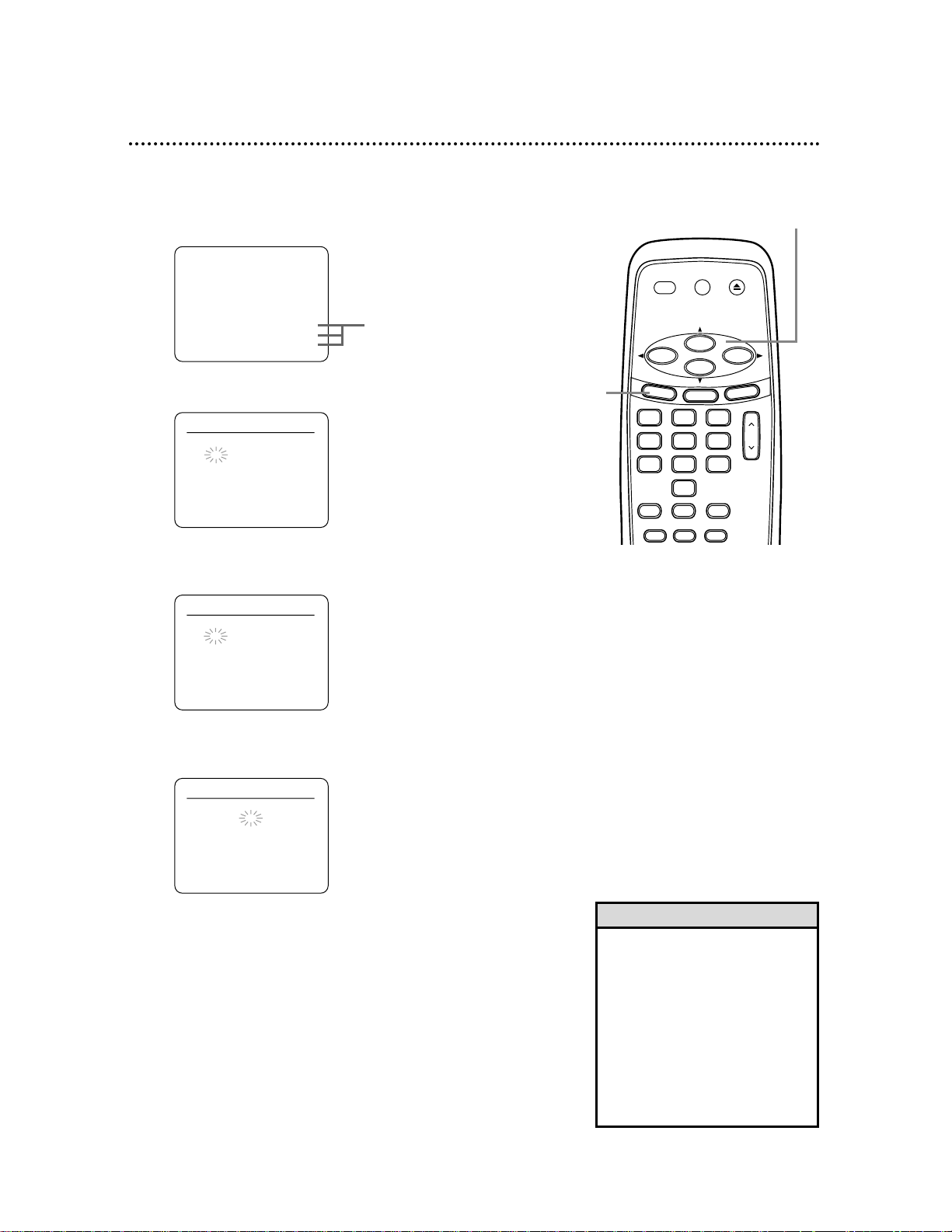
Press MENU until MENU appears.
• If the clock has never been set,
the CLOCK SET menu may
appear immediately when you
press MENU. If this happens, follow the instructions from step 3
above.
• To display the time on the TV,
press STATUS repeatedly.
• Power failures exceeding 30 seconds can erase your clock setting.
• Press REW to go back one step.
Helpful Hints
1
2-4
- M E N U -
B TIMER PROGRAMMING
AUTO REPEAT [OFF]
CHANNEL SET UP
CLOCK SET
LANGUAGE SELECT
AUDIO OUT
TV STEREO [ON]
SAP
CLOCK SET
MONTH DAY YEAR
– – / – –– – – –
HOUR MINUTE AM/PM
– – : – –– –
2
Press PLAY or STOP repeatedly to select CLOCK
SET. Press F.FWD.
3
While MONTH is flashing, press PLAY or STOP
repeatedly until the desired month appears.
Press F.FWD.
4
While DAY is flashing, press PLAY or STOP repeatedly until the desired day appears. Press F.FWD.
MVR650MG/17 only
CLOCK SET
MONTH DAY YEAR
0 3 / – –– – – –
HOUR MINUTE AM/PM
– – : – –– –
CLOCK SET
MONTH DAY YEAR
0 3 / 1 8 – – – –
HOUR MINUTE AM/PM
– – : – –– –
Page 15
CH
321
654
987
0
POWER
STATUS
SLOWREC MEMORY
SPEED
SEARCH MODE STILL/PAUSE
VCR/TV EJECT
M
ENU
CLEAR
REW
PLAY
STOP
F.FWD
Setting the Clock (cont’d) 15
• To reset the clock, follow steps 1-2
on page 14. Select information to
change using F.FWD or REW.
When the desired information is
flashing, use PLAY or STOP to
enter the correct information.
Press CLEAR to remove the menu.
Helpful Hint
CLOCK SET
MONTH DAY YEAR
0 3 / 1 8 THU 2 0 0 4
HOUR MINUTE AM/PM
0 5 : 4 0 – –
CLOCK SET
MONTH DAY YEAR
0 3 / 1 8 THU 2 0 0 4
HOUR MINUTE AM/PM
0 5 : 4 0 P M AM
B PM
5-9
9
5
While YEAR is flashing, press PLAY or STOP repeatedly until the desired year appears. Press F.FWD. The
day of the week will appear automatically.
6
While HOUR is flashing, press PLAY or STOP
repeatedly until the desired hour appears.
Press F.FWD.
7
While MINUTE is flashing, press PLAY or STOP
repeatedly until the desired minute appears.
Press F.FWD.
8
While AM/PM is flashing, press PLAY or STOP repeatedly to point to AM or PM. Your selection will flash on the
screen in the AM/PM space.
9
Press CLEAR or F.FWD to start the clock.
CLOCK SET
MONTH DAY YEAR
0 3 / 1 8 THU 2 0 0 4
HOUR MINUTE AM/PM
– – : – –– –
CLOCK SET
MONTH DAY YEAR
0 3 / 1 8 THU 2 0 0 4
HOUR MINUTE AM/PM
0 5 : – –– –
Page 16

CH
321
654
987
0
POWER
STATUS
SLOWREC MEMORY
SPEED
SEARCH MODE STILL/PAUSE
VCR/TV EJECT
M
EN
U
CLEAR
REW
PLAY
STOP
F.FWD
16 Language Selection
Follow the steps below to change the language of the on-screen
menus and displays.Make sure:
● The VCR is on and in VCR position. (The VCR/TV light will appear.
If it does not,press VCR/TV once.)
1
Press MENU until MENU appears.
1
2-3
• If you accidentally select Spanish
or French and need English:
1)Press MENU until MENU appears.
2) Press PLAY or STOP repeatedly to
choose SELEC. IDIOMA or SELECTION LANGUE. Press F.FWD.
3) Press PLAY or STOP to select
ENGLISH.
4) Press CLEAR to remove the menu.
Helpful Hint
4
- M E N U -
B TIMER PROGRAMMING
AUTO REPEAT [OFF]
CHANNEL SET UP
CLOCK SET
LANGUAGE SELECT
AUDIO OUT
TV STEREO [ON]
SAP
- M E N U -
TIMER PROGRAMMING
AUTO REPEAT [OFF]
CHANNEL SET UP
CLOCK SET
B LANGUAGE SELECT
AUDIO OUT
TV STEREO [ON]
SAP
LANGUAGE SELECT
B ENGLISH [ON]
FRANCAIS
ESPAÑOL
2
Press PLAY or STOP repeatedly to select LANGUAGE SELECT. Press F.FWD.
3
Press PLAY or STOP to select ENGLISH, FRANCAIS, or ESPAÑOL. [ON] will appear beside your choice.
4
Press CLEAR to remove the menu.
MVR650MG/17 only
MVR650MG/17 only
Page 17

On-Screen Status Displays 17
You may access on-screen status displays by pressing STATUS repeatedly. Displays may include the current
time, channel, and other information.
● Press STATUS once.The COUNT on-screen status display will appear for five seconds.After five seconds,
only the real-time counter will appear on the screen.This counter shows you the elapsed playing time of
the tape (from the point at which the real-time counter was set to zero).
● Press STATUS once again.The CLOCK on-screen status display will appear for five seconds.After five
seconds,only the current time will appear on the screen (the clock must be set).If you are watching TV,
the current channel number and the availability of stereo or second audio (MVR650MG/17 only) will also
appear on the screen.
● Press STATUS once again.The on-screen status display will disappear.
• If the channel you select has no
broadcast, the screen will be blue.
• Access a status display any time
by pressing STATUS. (The exception is when viewing a still picture
or a slow motion picture, or during
forward and reverse searching.)
• Channel numbers appear on the
screen for a few seconds at each
channel change.
Helpful Hints
<OFF mode>
<COUNT mode>
STOP
SLP 0:12:34 HIFI
<CLOCK mode>
STOP 5:40 PM
CH 02
STEREO
SAP
SLP
Press STATUS once.
Press STATUS once.
Press STATUS once.
MVR650MG/17 only
This indicates HIFI has been selected for AUDIO OUT
(see page 41). If you play non-Hi-Fi tapes while the VCR is
set to HIFI,or if MONO has been selected for AUDIO
OUT, HIFI will not appear on the status display.
<OFF mode>
MVR650MG/17 only
Page 18

EJECT Button
Press to eject the tape.
VCR/TV Button
Select the signal your TV receives from the VCR.
● VCR Position
Watch a tape, watch a program while recording it,or watch TV
using CH or the Number buttons to change channels at
the VCR. The VCR/TV light appears when in VCR position.
● TV Position
Watch TV (changing channels at the TV) or watch one program
while recording another. See page 31.
POWER Button
Press to turn the VCR on or off.
PLAY Button
Press to play a tape.Also, press to release Slow,Search,or Still
mode and return to normal play. See page 34. Use to select an
item in the menu or enter information in the menu.
MENU Button
Press repeatedly to access menus or to remove menus.
Number Buttons
Press to select channels at the VCR .
Enter channel numbers as a two-digit number for the quickest
results.For example,to select channel 6, press 0,6. If you only
press the Number 6 button,channel 6 will appear after a brief
delay. (There also may be a brief delay when you select channels
10,11, and 12.) To select channels 100 and above,enter channel
numbers as a three-digit number. For example, to select channel
117,press 1,1, 7.
REC Button
Press to start a recording or a
timed One-Touch Recording.
See pages 24-25.
MEMORY Button
Press to memorize a tape position.See page 35.
SLOW Button
Press for slow motion play. See page 34.
CH Button
Press to scan through the VCR’s available channels.
See pages 12-13.
Press to adjust tracking.See page 38.
18 Remote Control
CH
321
654
987
0
POWER
STATUS
MEMORY SLOWREC
SPEED
SEARCH MODE STILL/PAUSE
VCR/TV EJECT
MENU
CLEAR
REW
PLAY
STOP
F.FWD
Page 19

Remote Control (cont’d) 19
F.FWD Button
Press to fast forward the tape.See page 34.
Press to change a menu item or to go to the next menu.
Press to add or delete channel numbers.See page 13.
STOP Button
Press to stop the tape.
Press to select a menu item or to change information in the menu.
REW Button
Press to rewind a tape.See page 34.
Press to erase a timer recording.See page 29.
Press to go back one menu step.
Press to add or delete channel numbers.See page 13.
STATUS Button
Press to access or remove the status display. See page 17.
SPEED Button
Press to select a recording speed (SP or SLP).
See pages 24 and 44.
SEARCH MODE Button
Press to set an Index or Time Search.See pages 36-37.
STILL/PAUSE Button
Press to pause or resume recording. See page 24. You cannot
pause a One-Touch Recording. See page 25.
During play, press to freeze the picture. Press repeatedly to
advance the picture frame by frame.
CLEAR Button
Press to remove menus.
Press to reset the real-time counter to zero.See page 35.
CH
321
654
987
0
POWER
STATUS
SLOWREC MEMORY
SPEED
SEARCH MODE STILL/PAUSE
VCR/TV EJECT
MENU
CLEAR
REW
PLAY
STOP
F.FWD
Page 20

20 Display Panel
POWER
VCR/TV CST.IN TIMER REC
POWER
VCR/TV CST.IN TIMER REC
VIDEO L AUDIO R
POWER RECORD REW PLAY F.FWDSTOP/EJECTCHANNEL
Cassette Compartment
Insert a video cassette here.
VCR Display Panel
Information about VCR operations
appears here.
VCR/TV Light
This green light appears when the
VCR is in VCR position.
REC(ord) Light
This red light appears during recording.
It flashes when recording is paused.
CST.IN Light
This green light appears when a tape is in the VCR.
POWER Light
This red light indicates the VCR
power is on.
TIMER Light
This red light glows when the VCR is turned
off to set a timer recording or during a OneTouch Recording or timer recording.It flashes
if the power is off for a timer recording,but
there is no tape in the VCR. It flashes when all
timer recordings are finished.
MVR650MG/17
Page 21

Front Panel 21
Remote Sensor
Receives a signal from your
remote so you can operate
your VCR from a distance.
CHANNEL
o/p
Buttons
Press to scan through the
VCR’s channels.
During normal or slow
motion play, press to adjust
the tracking.See page 38.
POWER Button
Press to turn the VCR
power on and off.
F.FWD (Fast Forward)
Button
Press to fast forward a
tape. See page 34. Press to
select a menu item.
REW(ind) Button
Press to rewind the tape.
See page 34. Press to go
back one step in some
menus.
POWER
VCR/TV CST.IN TIMER REC
VIDEO L AUDIO R
POWER RECORD REW PLAY F.FWDSTOP/EJECTCHANNEL
VIDEO/AUDIO In Jacks
Connect video and audio cables coming from the video
and audio out jacks of a camcorder, another VCR, or
other audio/video equipment here.See page 32.The
MVR650MG/17 is shown here.The MVR440MG/17 and
MVR450MG/17 have only one AUDIO IN Jack.
RECORD Button
Press once to start a recording.See page 24. Press repeatedly to start a timed One-Touch Recording.See page 25.
STOP/EJECT Button
Press once to stop the tape. When play is stopped,press
to eject the tape.
Press to select an item in the VCR menu.
PLAY Button
Press to play a tape.Also, press to release Slow,Search,
or Still mode and return to normal play. See page 34.
Press to select an item in the VCR menu.
MVR650MG/17
Page 22

VIDEO IN Jack
Connect a video cable coming from the video out
jack of a camcorder, another VCR, or an audio-visual
source (laser disc player, video disc player, etc.) here.
See page 32.
ANT(enna) IN Jack
Connect your antenna or Cable TV
signal here.See pages 6-10.
OUT Jack
Use the supplied RF coaxial cable to
connect this jack to the Antenna In
Jack on your TV or Cable Box/Satellite.
See pages six-nine.
VIDEO OUT Jack
Connect a video cable going to the video in jack of
a camcorder, another VCR, a TV, or an audio-visual
system (laser disc player,video disc player, etc.) here.
See pages 10, 32, and 39.
AC Power Cord
Connect to a standard AC outlet
to supply power to the VCR.
ANT
AUDIO
VIDEO
IN
OUT
OUT IN
OUT
L
R
IN
22 Rear Panel
AUDIO IN Jacks
Connect the audio cables coming from the audio out jacks of a camcorder, another VCR, or an audio source here.See page 32.
The MVR650MG/17 is shown here.The MVR440MG/17 and MVR450MG/17
have only one AUDIO IN Jack.
AUDIO OUT Jacks
Connect the audio cables going to the audio in jacks of a camcorder,
another VCR,a stereo amplifier, a TV, or an audio system here. See
pages 10, 32, and 39.
The MVR650MG/17 is shown here.The MVR440MG/17 and
MVR450MG/17 have only one AUDIO OUT Jack.
MVR650MG/17
Page 23

CH
321
654
987
0
POWER
STATUS
SLOWREC MEMORY
SPEED
SEARCH MODE STILL/PAUSE
VCR/TV EJECT
M
EN
U
CLEAR
REW
PLAY
STOP
F.FWD
Playing 23
Read and follow the steps below to play a tape.
1
Turn on the TV and set it to channel 3 or 4 (the
VCR’s RF output channel).(Press and hold PLAY during
tape play for three seconds to switch the VCR’s RF output
channel to 3 or 4.Channel 3 is the default setting.)
2
Insert a tape in the VCR. The POWER,VCR/TV, and
CST.IN lights will appear.If the tape’s record tab has been
removed,play will begin automatically.
3
If play does not start automatically, press PLAY.
4
Press STOP to stop play.
5
Press REW to rewind the tape.
6
Press EJECT to remove the tape.
Turn on the TV.
Insert a tape.
3
1
2
• If the tape you want to play is in
the VCR, make sure the VCR
power is on and the VCR is in VCR
position. (Press VCR/TV so the
VCR/TV light appears.) Press PLAY.
• Other playback options and features are on pages 33-41.
• If AUTO REPEAT is ON, play will
begin automatically, even when
the record tab is intact. See page
33.
• If you used audio and video cables
to connect the VCR to the TV as
shown on page 10, set the TV to
its Video In or Auxiliary In channel
instead. See your TV manual for
details.
Helpful Hints
6
4
5
Page 24

CH
321
654
987
0
POWER
STATUS
SLOWREC MEMORY
SPEED
SEARCH MODE STILL/PAUSE
VCR/TV EJECT
M
E
N
U
CLEAR
REW
PLAY
STOP
F.FWD
Read and follow the steps below to record a television program.
1
Turn on the TV; set it to channel 3 or 4 (the VCR’s RF
output channel). (Press and hold PLAY during tape play for
three seconds to switch the VCR’s RF output channel to 3
or 4.Channel 3 is the default setting.)
2
Insert a tape with its record tab intact (see page
five) in the VCR. The POWER,VCR/TV, and CST.IN lights
will appear. If the VCR/TV light does not appear, press
VCR/TV so the VCR/TV light appears.
3
Press SPEED until the desired tape speed (SP or
SLP) appears on the screen. The tape speed will disap-
pear after about five seconds.
You can change the tape speed while the VCR is recording,
but some distortion may appear on the tape.See page 44.
4
Use CH or the Number buttons to select a
channel to record.
5
Press REC once to start recording. The red REC(ord)
light will appear. If the tape is missing the record tab, the
VCR will eject the tape.
6
To pause recording (for example, during commercials), press STILL/PAUSE once. The REC(ord) light
will flash.
To resume recording, press REC or STILL/PAUSE
again. The REC(ord) light will stay on.
7
Press STOP to stop recording.
24 Recording
Turn on the TV.
Insert a tape.
1
2
• Other recording options are on
pages 25-32.
• The VCR will record in a preset volume.
• Pause will switch to Stop after five
minutes to protect the VCR and
the tape from damage. Review the
pause time remaining with the
■
marks on the screen. Each
■
mark equals one minute. During
the last minute of paused recording, the ■mark will flash.
• You cannot start a recording if a
VCR menu is on the TV screen.
• If you used audio and video cables
to connect the VCR to the TV as
shown on page 10, set the TV to
its Video In or Auxiliary In channel
instead. See your TV manual for
details.
Helpful Hints
6
7
4
3
5
Page 25

One-Touch Recording 25
One-Touch Recording lets you program an immediate timed
recording 30 minutes to eight hours long. Make sure:
●Channels are set.
●The desired recording speed (SP, SLP) has been selected with
SPEED.
●There is a tape in the VCR. Make sure the tape’s record tab is
intact and the tape is long enough to record the program(s).
●The VCR is in VCR position. (The VCR/TV light will appear.If it
does not,press VCR/TV once.)
1
Use CH or the Number buttons to select the
channel you want to record.
2
Press REC (or RECORD on the VCR) repeatedly until
the desired recording length (30 minutes to eight
hours) appears in the upper left corner of the screen.
Recording will begin immediately.The TIMER and REC(ord)
lights will appear on front of the VCR.
3
To stop an OTR before recording is finished, press
STOP on the remote or STOP/EJECT on the VCR.
To cancel the OTRbut continue recording,press REC or
RECORD repeatedly until REC appears in the upper left corner of the screen.
When the OTR is finished,the VCR will eject the tape and
turn itself off.
OTR (0:30)
SP
• To change the recording length
while an OTR is in progress, press
REC or RECORD repeatedly until
the desired length appears on the
screen.
• You cannot pause OTR recording.
• If the preset time for a timer
recording comes up during an
OTR, the OTR has priority.The
timer recording will not occur.
• To show the time remaining for an
OTR, press STATUS repeatedly
until OTR and the time remaining
appear on the screen.
• If the end of the tape is reached
during an OTR, the VCR will stop
recording, eject the tape, and turn
itself off.
Helpful Hints
2
3
CH
321
654
987
0
POWER
STATUS
SLOWREC MEMORY
SPEED
SEARCH MODE STILL/PAUSE
VCR/TV EJECT
M
EN
U
CLEAR
REW
PLAY
STOP
F.FWD
1
Page 26

CH
321
654
987
0
POWER
STATUS
SLOWREC MEMORY
SPEED
SEARCH MODE STILL/PAUSE
VCR/TV EJECT
M
E
NU
CLEAR
REW
PLAY
STOP
F.FWD
PROGRAM NUMBER 1
B ONCE
DAILY
WEEKLY
26 Timer Recording
Your VCR can record TV programs while you’re away. You can pro-
gram up to eight timer recordings.For each one,the VCR will turn
itself on,record,and turn itself off. Make sure:
●Channels are set.
●The clock is set.
●There is a tape in the VCR. Make sure the tape’s record tab is
intact and the tape is long enough to record the program(s).
●The VCR is in VCR position. The VCR/TV light will appear.If it
does not,press VCR/TV once.
1
Press MENU until MENU appears. Press PLAY or
STOP to select TIMER PROGRAMMING. Press
F.FWD. Available program numbers will flash.
PROGRAM NUMBER 1
DATE – – / – –
STAR T TIME – – :– – – –
END TIME – – :– – – –
CHANNEL – –
REC SPEED – –
1-3
1
TIMER PROGRAMMING
PROG. 12345678
DATE
STAR T TIME
END TIME
CHANNEL
REC SPEED
• Only programs that air MondayFriday can be recorded on a
DAILY basis. If you select DAILY
at step 3, then enter a Saturday
or Sunday DATE at step 4, the
correct program will not record.
The VCR will alter the recording
date and record a different program than you intended.
Helpful Hint
2
Press PLAY or STOP repeatedly to select a program
number. Press F.FWD. (If you select a program number
that already has a timer recording stored,information about
that program will appear. Press PLAY or STOP to select
another program number.)
3
Press PLAY or STOP repeatedly to select a ONCE,
DAILY, or WEEKLY recording.When the arrow is
beside your choice, press F.FWD.
● ONCE - The VCR will record a TV program on any day
you choose,up to 12 months away.
● DAILY - The VCR will record a TV program at the same
time on the same channel every day, Monday through Friday.
●WEEKLY - The VCR will record a TV program at the same
time on the same channel every week,for example,every
Monday.
Page 27

ONE TIME PROGRAM
PROGRAM NUMBER 1
DATE 0 5 / 0 4 TUE
START TIME 0 7 :3 0 P M
END TIME – – :– – – –
CHANNEL – –
REC SPEED – –
AM
BPM
ONE TIME PROGRAM
PROGRAM NUMBER 1
DATE 0 5 / 0 4 TUE
STAR T TIME – – :– – – –
END TIME – – :– – – –
CHANNEL – –
REC SPEED – –
Timer Recording (cont’d) 27
Instructions continue on page 28.
CH
321
654
987
0
POWER
STATUS
SLOWREC MEMORY
SPEED
SEARCH MODE STILL/PAUSE
VCR/TV EJECT
M
EN
U
CLEAR
REW
PLAY
STOP
F.FWD
• You cannot access the TIMER
PROGRAMMING menu at step 1
if the clock is not set.The CLOCK
SET menu will appear. See pages
14-15 to set the clock.
• Enter information while the space
is flashing.
• Press REW to go back one step.
• To stop a started timer recording,
press STOP/EJECT on the VCR.
More Helpful Hints are on
pages 42-43.
Helpful Hints
4
Enter the date of the recording. Press PLAY or STOP
repeatedly until the desired month appears. Press
F.FWD.
Next, press PLAY or STOP repeatedly until the
desired day appears. Press F.FWD.
The day of the week
will appear. You cannot program the VCR to record more
than one year in advance.
5
Enter the recording’s start time .
Press PLAY or STOP repeatedly until the desired
hour appears. Press F.FWD.
Press PLAY or STOP repeatedly until the desired
minute appears. Press F.FWD.
Finally, press PLAY or STOP to point to AM or PM.
AM or PM will flash beside the start time. Press F.FWD.
6
Repeat the procedure in step 5 to set the recording’s
end time.
4-6
ONE TIME PROGRAM
PROGRAM NUMBER 1
DATE 0 5 / 0 4 TUE
START TIME 0 7 :3 0 P M
END TIME 0 8 : 3 0 P M
CHANNEL – –
REC SPEED – –
AM
BPM
Page 28

CH
321
654
987
0
POWER
STATUS
SLOWREC MEMORY
SPEED
SEARCH MODE STILL/PAUSE
VCR/TV EJECT
M
ENU
CLEAR
REW
PLAY
STOP
F.FWD
28 Timer Recording (cont’d)
ONE TIME PROGRAM
PROGRAM NUMBER 1
DATE 0 5 / 0 4 TUE
START TIME 0 7 :3 0 P M
END TIME 0 8 : 3 0 P M
CHANNEL 16
REC SPEED – –
ONE TIME PROGRAM
PROGRAM NUMBER 1
DATE 0 5 / 0 4 TUE
START TIME 0 7 :3 0 P M
END TIME 0 8 : 3 0 P M
CHANNEL 1 6
REC SPEED S P
B SP
SLP
Turn off the VCR for the recording.
Insert a tape in the VCR.
Leave the Cable Box/Satellite on
(if applicable).
10
7-8
9
• When recording from line input
(other equipment connected to
the VCR), connect audio/video
cables to the audio/video in jacks
on the VCR.
If you use the AUDIO/VIDEO In
jacks on the front of the VCR,
choose L2.
If you use the AUDIO IN and
VIDEO IN jacks on the back of
the VCR, choose L1. (For example, see illustration on page 32.)
Helpful Hint
7
Select the channel you want to record. Press PLAY or
STOP repeatedly until the desired channel number
appears. Press F.FWD.
● If you are using a standard antenna/Cable TV hookup (as
shown on pages six-seven),select the channel of the TV program you want to record.
● If you are recording from line input,select L1 (LineIn Rear)
or L2 (LineIn Front). See the Helpful Hint below.
● If you are using a Cable Box/Satellite,select the Cable
Box/Satellite output channel (03 or 04).Then, at the Cable
Box/Satellite,select the channel you want to record.Leave
the Cable Box/Satellite on for the recording. See page eight.
8
Press PLAY or STOP repeatedly to select a tape
speed. The arrow will appear beside your choice.The select-
ed tape speed will flash beside REC SPEED.See page 44.
9
Press CLEAR to save the timer recording.
10
Press POWER to turn off the VCR. The red TIMER
light will appear. (It will flash if there is not a tape in the
VCR.)
If the recording is several hours or days away, you may use
the VCR until time for the recording.Just turn off the VCR
about five minutes before the scheduled start time.
The VCR will not remind you of upcoming recordings.
Page 29

CH
321
654
987
0
POWER
STATUS
SLOWREC MEMORY
SPEED
SEARCH MODE STILL/PAUSE
VCR/TV EJECT
M
EN
U
CLEAR
REW
PLAY
STOP
F.FWD
Timer Recording (cont’d) 29
4
1
1-3
2
Press PLAY or STOP repeatedly to select the program you want to cancel.
3
While the program number is flashing, press REW to
cancel the timer recording.
4
Press CLEAR to remove the menu.
Cancelling a Timer Recording
1
First, press MENU until MENU appears.
Press PLAY or STOP repeatedly to select TIMER
PROGRAMMING. Press F.FWD.
TIMER PROGRAMMING
PROG. 12345678
DATE
STAR T TIME
END TIME
CHANNEL
REC SPEED
ONE TIME PROGRAM
PROGRAM NUMBER 1
DATE 05/04 TUE
START TIME 07:30 PM
END TIME 08:30 PM
CHANNEL 16
REC SPEED SP
Page 30

CH
321
654
987
0
POWER
STATUS
SLOWREC MEMORY
SPEED
SEARCH MODE STILL/PAUSE
VCR/TV EJECT
M
EN
U
CLEAR
REW
PLAY
STOP
F.FWD
30 Timer Recording (cont’d)
Correcting a Timer Recording
You can correct a timer recording after you have finished setting it.
Make sure the VCR is on and in VCR position. (The VCR/TV light
will appear. If it does not, press VCR/TV once.)
1
First, press MENU until MENU appears. Press PLAY
or STOP repeatedly to select TIMER PROGRAMMING. Press F.FWD.
2
Press PLAY or STOP repeatedly to select the timer
recording you want to correct.
1
5
1-4
3
Select the information you want to change by repeatedly pressing F.FWD. Press REW to go back one step.
(There is an exception.Do not press REW while the program number is flashing. This will cancel the timer recording
completely.)
4
While the information is flashing, enter the correct
information by pressing PLAY or STOP.
5
When all the information is correct, press CLEAR to
save the timer recording. Turn off the VCR before the
timer recording.
ONE TIME PROGRAM
PROGRAM NUMBER 1
DATE 05/04 TUE
START TIME 07:30 PM
END TIME 08:30 PM
CHANNEL 16
REC SPEED SP
Page 31

CH
321
654
987
0
POWER
STATUS
SLOWREC MEMORY
SPEED
SEARCH MODE STILL/PAUSE
VCR/TV EJECT
M
EN
U
CLEAR
REW
PLAY
STOP
F.FWD
Recording One Channel/Watching Another 31
• If you use a Cable Box/Satellite,
you may not be able to watch
one channel while recording
another. See pages eight-nine.
Helpful Hint
1
Select the channel you
want to watch at the TV.
3
2,5
6
Set the TV to channel
3 or 4.
4
1
Press REC to start recording the current channel.
See page 24.
2
Press VCR/TV to put the VCR in TV position. The
VCR/TV light will disappear.
3
Use the TV remote control to select the channel you
want to watch at the TV.
4
To return to the channel being recorded, use the TV
remote control to select channel 3 or 4, whichever
channel the RF output channel of the VCR is set to.
Choose the channel it was on before you changed it at step 3.
5
Press VCR/TV on the VCR’s remote to put the VCR
back in VCR position. The green VCR/TV light will reappear.
The channel being recorded will appear on the screen.
6
To stop recording, press STOP.
Page 32

32 Rerecording (Tape Duplication)
• If you connected another VCR to
the AUDIO/VIDEO IN jacks on the
back of VCR 2, press 0, 0, 1 at
step 5. L1 will appear on the TV.
• If you connected another VCR to
the AUDIO/VIDEO In jacks on
front of VCR 2, press 0, 0, 2 at
step 5. L2 will appear on the TV.
• When the VCR is set to L1 or L2,
the screen is blue.
• Unauthorized recording of copyrighted TV programs, video tapes,
or other materials may infringe on
the rights of copyright owners and
violate copyright laws. A copy-protected program will not record
clearly.
• Audio and video cables are not
supplied.
• If you have the MVR440MG/17
or MVR450MG/17, connect one
audio cable to the AUDIO OUT
jack on VCR1 and to the AUDIO
IN jack on VCR2.
Helpful Hints
ANT
AUDIO
VIDEO
IN
OUT
OUT IN
OUT
L
R
IN
ANT
AUDIO
VIDEO
IN
OUT
OUT IN
OUT
L
R
IN
VCR 1
Playing VCR
VCR 2 Recording VCR
1.Audio cables from AUDIO OUT Jacks
of VCR 1 to AUDIO IN Jacks of VCR 2
2.Video cable from VIDEO OUT Jack of VCR
1 to VIDEO IN Jack of VCR 2
3.RF coaxial cable
from the OUT
jack of VCR 2 to
the TV’s ANTEN-
NA IN Jack
1
Make the connections shown above.
2
VCR 1 will play your tape. Insert a prerecorded tape
in VCR 1. If the tape does not have a record tab,play
begins.If this happens, press STOP/EJECT on VCR 1 once.
3
VCR 2 will record your tape. Insert a blank tape in
VCR 2. Make sure the record tab is intact (see page five).
Make sure VCR 2 is on and in VCR position. (The green
VCR/TV light will appear. If it does not, press VCR/TV once.)
4
Turn on the TV and set it to channel 3 or 4 (the RF
output channel of VCR 2). See page seven.
5
Point the remote at VCR 2. Press 0, 0, 1 or 0, 0, 2. (See
Helpful Hints at right.)
6
Point the remote at VCR 2. Use SPEED to select SP
or SLP.
7
Press PLAY on VCR 1 and RECORD on VCR 2 at the
same time.
8
To stop recording, press STOP/EJECT on VCR 2
once, then stop the tape on VCR 1.
These instructions show you how to copy tapes using two
MVR650MG/17 VCRs.
Different VCRs may operate differently.
Page 33

CH
321
654
987
0
POWER
STATUS
SLOWREC MEMORY
SPEED
SEARCH MODE STILL/PAUSE
VCR/TV EJECT
M
E
NU
CLEAR
REW
PLAY
STOP
F.FWD
Repeat Play 33
Follow the steps below to program the VCR to play a tape over and
over. Make sure:
●The VCR is on and is in VCR position. The VCR/TV light will
appear on the front panel.If it does not,press VCR/TV once.
●There is a tape in the VCR.
1
Press MENU until MENU appears.
1
3
2
• To cancel AUTO REPEAT, follow
steps 1-2 above. At step 3, press
F.FWD so [OFF] appears beside
AUTO REPEAT. Press CLEAR to
remove the menu.
• MEMORY does not function if
AUTO REPEAT is [ON].
• The real-time counter memory is
cancelled if AUTO REPEAT is
[ON].
Helpful Hints
2
Press PLAY or STOP repeatedly to select AUTO
REPEAT.
3
Press F.FWD so [ON] appears beside AUTO
REPEAT. Tape play will begin immediately.AUTO REPEAT
B will appear on the screen briefly.
(If you are fast forwarding or rewinding the tape,you must
first press CLEAR to remove the menu,then press PLAY to
play the tape.
The VCR will play the tape to the end,rewind it,then play it
again.(TV programming will appear on the screen while the
tape is rewinding.)
MVR650MG/17 only
- M E N U -
B TIMER PROGRAMMING
AUTO REPEAT [OFF]
CHANNEL SET UP
CLOCK SET
LANGUAGE SELECT
AUDIO OUT
TV STEREO [ON]
SAP
- M E N U -
TIMER PROGRAMMING
B AUTO REPEAT [OFF]
CHANNEL SET UP
CLOCK SET
LANGUAGE SELECT
AUDIO OUT
TV STEREO [ON]
SAP
MVR650MG/17 only
- M E N U -
TIMER PROGRAMMING
B AUTO REPEAT [ON]
CHANNEL SET UP
CLOCK SET
LANGUAGE SELECT
AUDIO OUT
TV STEREO [ON]
SAP
MVR650MG/17 only
Page 34

34 Special Effects Playback
• Slow and Still modes will automatically switch to Stop mode after
five minutes to protect the VCR
and the tape from damage.
Helpful Hint
Forward and Reverse Searching
1
During tape play, press and release F.FWD or REW.
A fast forward or reverse picture search will begin.
2
Press F.FWD or REW again. The VCR will search in
super high speed.(This is possible only for tapes recorded in
LP or SLP speeds.) Each press of F.FWD or REW alternates
the search speed.
3
To return to play, press PLAY.
Viewing a Still Picture
1
During play, press STILL/PAUSE to freeze the picture.
Advance the still picture one frame at a time by pressing
STILL/PAUSE repeatedly.
2
To release the still picture and return to normal play,press
PLAY.
Viewing a Slow Motion Picture
1
During tape play, press SLOW. The tape will play in slow
motion.
2
To release Slow mode and return to normal play,press
PLAY.
POWER
REW
M
EN
U
SEARCH MODE STILL/PAUSE
SPEED
VCR/TV EJECT
PLAY
STOP
STATUS
0
SLOWREC MEMORY
F.FWD
CLEAR
321
CH
654
987
Page 35

Real-Time Counter Memor y 35
You can reset the real-time counter to zero at a tape location you
want to refer to later. Make sure:
●The VCR is on and is in VCR position. The VCR/TV light will
appear. If it does not, press VCR/TV once.
●There is a tape in the VCR.
1
Play, fast forward, or rewind a tape to the location that you
would like to refer to later. Press STOP to stop the tape.
2
Press CLEAR (repeatedly if necessary) to reset the
real-time counter to zero.
• Set the counter memory at one
location at a time. Setting the
counter to zero at a second location will erase the previous setting.
• To erase the counter memory,
press MEMORY repeatedly so the
M disappears from the screen.
• MEMORY does not function if
AUTO REPEAT is [ON].
See page 33.
Helpful Hints
2
1,4
3
CH
321
654
987
0
POWER
STATUS
SLOWREC MEMORY
SPEED
SEARCH MODE STILL/PAUSE
VCR/TV EJECT
M
EN
U
CLEAR
REW
PLAY
STOP
F.FWD
3
Press MEMORY so M appears on the screen beside
the real-time counter.
4
To go to a tape location where the counter was reset
to zero, press REW or F.FWD when play is stopped.
When the tape reaches zero,it will stop.Press PLAY to
watch the tape.
M 0 :00 : 00
0 :00 : 00
Page 36

36 Time Search
Time Search lets you go to a specific point on a tape.Enter the
amount of time you wish to skip in order to reach the specified
point.Make sure:
● The VCR is on and is in VCR position. (The VCR/TV light will
appear. If it does not, press VCR/TV once.)
● There is a tape in the VCR.
1
Press SEARCH MODE until TIME SEARCH appears.
• You can set a Time Search for up
to 9 hours, 59 minutes (9:59).
• Time Search is not available during recording.
• To exit Time Search mode, press
CLEAR.
• To cancel a Time Search in
progress, press STOP.
• If the end of the tape is reached
during a Time Search, the VCR will
cancel the search and rewind the
tape. See page 38.
Helpful Hints
2
Within 30 seconds, press PLAY or STOP repeatedly
until your desired length of time appears. Or,press and
hold PLAY or STOP until you reach the length of time.
3
Within 30 seconds, press REW or F.FWD. The VCR
begins rewinding or fast forwarding to the specified point.
The time counts down on the screen beneath TIME SEARCH
as the searching progresses. When the tape finishes rewinding
or fast forwarding,the VCR will start play automatically.
CH
321
654
987
0
POWER
STATUS
SLOWREC MEMORY
SPEED
SEARCH MODE STILL/PAUSE
VCR/TV EJECT
M
EN
U
CLEAR
REW
PLAY
STOP
F.FWD
1
2-3
TIME SEARCH
- :- -
TIME SEARCH
2 :5 0
TIME SEARCH
2 :5 0
D
Page 37

Index Search 37
When you make a recording,the VCR places an index mark at the
beginning of the recording.Essentially, an index mark is a type of
“bookmark” for your tape.This feature is useful if you have several
different programs recorded on a single tape.Skip over programs
by following the steps below. Before you begin,make sure:
●The VCR is on and is in VCR position. (The VCR/TV light will
appear. If it does not, press VCR/TV once.)
●There is a tape in the VCR.
1
Press SEARCH MODE until INDEX SEARCH
appears.
• When an index mark is passed
during rewinding or fast forwarding, the number of programs
beneath INDEX SEARCH
decreases by one.
• Up to 20 index marks may be
searched.
• This function is not available during recording.
• Press STOP to stop the search.
•
To exit Index Search, press CLEAR.
• The time gap between index
marks should be greater than 1
minute for SP recording, 2 minutes
for LP recording, and 3 minutes for
SLP recording.
• If the end of the tape is reached
during an Index Search, the VCR
will cancel the search and rewind
the tape. See page 38.
Helpful Hints
2
Within 30 seconds, press PLAY or STOP repeatedly
until the number of programs that you want to skip
appears beneath INDEX SEARCH.
This number should include the current program. For example, if you are currently viewing program 2 and you want to
skip to program 5,select 03 to skip three programs (2,3,and
4).Playback will begin at program 5. If you want to skip to
program 1,select 02 to skip two programs (2 and 1).
Playback will begin at program 1.
3
Within 30 seconds, press REW or F.FWD. The VCR
rewinds or fast forwards to the beginning of the program.
When the program is reached,play will begin.
INDEX SEARCH
--
Pro.1 Pro.2 Pro.3 Pro.4 Pro.5
02 01 01 02 03
Beginning
of tape
End
of tape
CURRENT PROGRAM
INDEX MARK
INDEX SEARCH
03
INDEX SEARCH
03
D
CH
321
654
987
0
POWER
STATUS
SLOWREC MEMORY
SPEED
SEARCH MODE STILL/PAUSE
VCR/TV EJECT
M
EN
U
CLEAR
REW
PLAY
STOP
F.FWD
1
2-3
Page 38

Automatic Playback
When you put a tape in the VCR, the power will come on automatically. If the tape’s record tab is missing,play will begin.(If a timer
recording is set,you may have to press POWER to turn on the
VCR. Turn off the VCR for the timer recording later. If you insert a
tape without a record tab when a timer recording is set,the VCR
will eject the tape.)
Automatic Rewind, Eject, Off
When a tape is played, fast forwarded,or recorded to its end,the
VCR will rewind the tape to the beginning,eject the tape,and turn
itself off.
If the real-time counter memory is set, the VCR will only rewind the
tape to the point at which the counter is set to zero,then stop.The
VCR will not eject the tape or shut itself off.
Tape Eject
A tape can be ejected with the VCR power on or off (but the VCR
must be plugged in). If a Timer Recording is programmed,a tape
can only be ejected with the power on. Be sure to insert a tape for
the Timer Recording, then turn off the VCR power.
Tracking
The VCR automatically adjusts tracking to give you the best possible
picture quality during normal play. With some recordings,you may
get a better picture using manual tracking.
To adjust the tracking manually, press CH on the remote or
CHANNEL
o/p
on the VCR during normal or slow motion play.
NOTES:
• Tracking returns to automatic tracking adjustment when you insert a
tape or stop play.
• Use CHANNEL
o/p
on the VCR or CH on the remote to
remove vertical jitter in a Still picture.
38 Automatic Playback Features
Before
Tracking
Adjustment
After
Tracking
Adjustment
Page 39

MTS Broadcast Stereo (MVR650MG/17) 39
Your VCR can play recordings broadcast in Hi-Fi (high fidelity) stereo,which produces a crisp, clear sound
from two sources. Your VCR also can play tapes recorded in a second audio (usually, that means your program is recorded in a second language). Of course, your VCR will play tapes recorded in monaural (singlesource) sound as well.
Your VCR also will record in Hi-Fi stereo or in second audio, so when you play back that tape on the VCR,
it will be in stereo or second audio.
Read the directions on this page to familiarize yourself with your VCR’s stereo and second audio setups.
Then follow the directions on page 40 to record in stereo or second audio and the directions on page 41
to play back tapes recorded in Hi-Fi stereo.
Understanding On-Screen Displays
When you receive a signal from a channel you’re watching, portions of the on-screen display shown below
will appear when you press STATUS on the remote.
The indication SAP or STEREO that appears on the status display tells you if
the program you’re watching is available in second audio or stereo.
Even though a program is available in second audio or stereo, you still must
program the VCR to receive or record the program. Follow the directions on
page 40. This indication is not available during tape play.
STOP 12:00 AM
CH 02
STEREO
SAP
SLP
To record and play back programs broadcast in stereo, even if you have a Single Speaker TV,just use one of
the connections shown,then follow the steps on pages 40-41.
R
L
VIDEO
IN
OUT
IN
OUT
AUDIO
OUT
IN
ANT
Stereo Amplifier
or Receiver
Monitor
TV
Single
Speaker TV
Stereo
Speaker TV
OR
R
L
For stereo sound, connect the audio cables to
the AUDIO OUT Jacks on the VCR and to the
AUDIO IN Jacks on the Stereo Amplifier or
Receiver.Then, connect the video cable to the
VIDEO OUT Jack of the VCR and to the
VIDEO IN Jack of a monitor TV.
OR, for monaural sound, connect only
the RF coaxial cable (supplied) to the
VCR’s OUT Jack and to the TV’s
ANTENNA IN Jack.
Page 40

CH
321
654
987
0
POWER
STATUS
SLOWREC MEMORY
SPEED
SEARCH MODE STILL/PAUSE
VCR/TV EJECT
M
EN
U
CLEAR
REW
PLAY
STOP
F.FWD
40 MTS Broadcast Stereo (MVR650MG/17) (cont’d)
• You can only receive and record
stereo or second audio if included
by the program. You can only play
in stereo or second audio tapes
that were recorded that way. See
page 39 to determine if the program is broadcast in stereo or second audio.
• If you select second audio when it
is not available, the VCR will record
normal audio.
Helpful Hints
Make sure:
●The VCR is on and is in VCR position. The VCR/TV light will
appear. If it does not, press VCR/TV once.
1
Press MENU until MENU appears.
1
2
3
2
Press PLAY or STOP repeatedly to select TV
STEREO or SAP. Press F.FWD, then [ON] will appear
beside your selection.
3
Press CLEAR to remove the menu.
4
To play a tape,press PLAY.
To record,use CH to select a channel, then press
REC.
- M E N U -
B TIMER PROGRAMMING
AUTO REPEAT [OFF]
CHANNEL SET UP
CLOCK SET
LANGUAGE SELECT
AUDIO OUT
TV STEREO [ON]
SAP
- M E N U -
TIMER PROGRAMMING
AUTO REPEAT [OFF]
CHANNEL SET UP
CLOCK SET
LANGUAGE SELECT
AUDIO OUT
B TV STEREO [ON]
SAP
Page 41

Hi-Fi Stereo (MVR650MG/17) 41
Multi-Channel Television Sound records in Hi-Fi stereo. To play
tapes in Hi-Fi stereo,follow these steps. Make sure:
●The VCR is on and is in VCR position. The VCR/TV light will
appear. If it does not, press VCR/TV once.
1
Press MENU until MENU appears.
• All programs record in both Hi-Fi
stereo and monaural sound.
• The audio level of a tape recorded
in Hi-Fi stereo will differ from the
audio level of a tape not recorded
in Hi-Fi stereo.
• You can set AUDIO OUT to
MONO if you want monaural
audio playback. Follow steps 1-2
above. At step 3, press PLAY or
STOP repeatedly to select MONO.
Press CLEAR to remove the menu.
• If you play non-Hi-Fi tapes while
AUDIO OUT is set to HIFI, HIFI
will not appear on the status display. The tape will play in monaural sound.
For more hints,see page
43.
Helpful Hints
CH
321
654
987
0
POWER
STATUS
SLOWREC MEMORY
SPEED
SEARCH MODE STILL/PAUSE
VCR/TV EJECT
M
EN
U
CLEAR
REW
PLAY
STOP
F.FWD
2-3
1
2
Press PLAY or STOP repeatedly to select AUDIO
OUT. Press F.FWD.
3
Press PLAY or STOP repeatedly to select HIFI. [ON]
will appear beside HIFI.
4
Press CLEAR to remove the menu.
4
- M E N U -
B TIMER PROGRAMMING
AUTO REPEAT [OFF]
CHANNEL SET UP
CLOCK SET
LANGUAGE SELECT
AUDIO OUT
TV STEREO [ON]
SAP
- M E N U -
TIMER PROGRAMMING
AUTO REPEAT [OFF]
CHANNEL SET UP
CLOCK SET
LANGUAGE SELECT
B AUDIO OUT
TV STEREO [ON]
SAP
AUDIO OUT
B HIFI [ON]
MONO
Page 42

If you are having problems with your product,check this list of problems and possible solutions before requesting service.You may be able to solve the problem yourself.
If you need to call a customer service representative,please know the model number and serial number of your
product before you call. This information is displayed on the back of the product.
The VCR has no power.
• Make sure the power plug is connected to an AC (alternating current) outlet.
• Make sure the power is on.
A power failure occurred.
• See page 11 to select a language and set up channels. See pages 14-15 to reset the clock.
• Timer recordings are lost if a power failure exceeds 30 seconds.Reset the recordings.See pages 26-30.
The remote will not operate the VCR.
• Aim the remote directly at the VCR’s remote sensor.See page 21.
• Remove all obstacles between the remote and the VCR.
• Inspect and/or replace the batteries in the remote control.See page five.
The VCR does not respond normally to the remote.
• Install new batteries (preferably alkaline) in the remote control.
The motor (cylinder) rotates even when the VCR is in Stop mode.
• To enable quick play, the cylinder will rotate for about five minutes.This is normal.
A TV program cannot be recorded.
• Check the connections between the VCR,TV, antenna/Cable TV signal,and Cable Box/Satellite.See pages 6-10.
• Make sure the tape has a record tab.See page five.
The VCR will not perform a timer recording.
• Make sure the start and end times are correct.See pages 26-30.
• Make sure a tape is in the VCR and the tape has a record tab. See page five.
• Make sure the VCR power is off. The VCR will not remind you of an upcoming timer recording if the VCR
power is on.
• Make sure the clock is set. See pages 14-15.
• The VCR may not complete a timer recording if the power fails for more than 30 seconds before or during
the recording,even if the power is restored.Set up channels and reset the clock before resetting the recording(s).
• Finish programming a timer recording at least five minutes before it is scheduled to begin.
• If,after programming a timer recording,you turn off the VCR without inserting a tape, the red TIMER light will
blink.Insert a tape with the record tab intact.If a tape without a record tab is inserted (when the power is off
for a timer recording),the VCR will eject the tape .The TIMER light will blink.
• Noon is 12 p.m.Midnight is 12 a.m.
• If the tape runs out before the recording ends,the VCR will stop,eject the tape,and turn itself off.The red
TIMER light will blink.
• If the preset time for a timer recording comes up during a One-Touch Recording,the OTR has priority.
• When two timer recordings overlap,the recording with the earliest start time has priority.When the earliest
program finishes recording,the next program will record (only the time remaining).
Tape cannot be removed.
• Make sure the power plug is connected to an AC (alternating current) outlet.
• If a timer recording is set,turn on the VCR and eject the tape . Insert a tape and turn off the VCR again for
your timer recording.
42 Helpful Hints
Page 43

Helpful Hints (cont’d) 43
Tape cannot be inserted.
• Insert the tape,window side up,with the record tab facing you and on the left.
• Make sure a tape isn’t already in the VCR by pressing STOP/EJECT on the VCR or EJECT on the remote.
• Gently push on the center of the tape when putting it in the VCR. Never force the tape into the VCR.
• If a timer recording is set and the VCR power is off,the VCR will not accept a tape that does not have a
record tab.You may only insert a tape with the record tab intact.
The tape ejects if you press REC or turn off the VCR for a timer recording.
• Make sure the tape has a record tab. See page five.
There is no picture or the picture is noisy or contains streaks.
• Set the TV to channel 3 or 4. See page seven. Adjust channel 3 or 4 at the TV.
• If you used audio and video cables to connect the VCR to the TV as shown on page 10, select the Video In
channel at the TV.
• Set the VCR to VCR position. (The green VCR/TV light will appear.If it does not, press VCR/TV once.)
• Adjust the tracking. See page 38.
• TVs placed too close to the VCR can cause interference during play.Move the VCR away from the TV.
TV programs cannot be watched normally.
• Press VCR/TV to put the VCR in TVposition. (The VCR/TV light will disappear.)
• Check the connections between the VCR,TV, antenna/Cable TV signal,and Cable Box/Satellite.See pages 6-10.
The reception on all channels is poor.
• You may need to tune your TV again.
Line Input
• If you accidentally enter Line Input mode (LineIn Rear (L1) or LineIn Front (L2) will appear on your TV
briefly),use CH or the Number buttons to select another channel.
The picture is too dim, too bright, or fluctuates in brightness.
• Some programs may be broadcast with copyright protection technology in order to protect the rights of
copyright owners.This technology is used on programs that are recorded on video tapes or Digital Video
Discs (DVDs),as well as some programs broadcast by antenna/cable/satellite television channels.Programs
broadcast with copyright protection technology may not record clearly.Likewise,if you play a tape that is a
recording of a copyright protected program,the picture may not be clear.Tapes of copyright protected programs may have a picture that is dark or dim,or the brightness of the picture may fluctuate.Therefore,you
should avoid recording or playing copies of copyright protected programs.
This VCR incorporates copyright protection technology that is protected by method claims of certain U.S.
patents and other intellectual property rights owned by Macrovision Corporation and other rights owners.
Use of this copyright protection technology must be authorized by Macrovision Corporation and is intended
for home and other limited viewing uses only, unless otherwise authorized by Macrovision Corporation.
Reverse engineering or disassembly is prohibited.
Hi-Fi Stereo Sound (MVR650MG/17 only)
•
During play, Hi-Fi audio may temporarily revert to normal audio when you adjust tracking.This is normal.
• When connecting the VCR to a stereo TV, you only get stereo sound if you use audio cables to connect the
VCR’s AUDIO OUT jacks to the TV’s AUDIO IN jacks. Put the TV in Line Input mode. Your TV may refer to
this as an Audio/Video In channel, or A/V In,External In,Auxiliary In,etc. Such channels are usually located
near channel zero (0).Or, your TV remote may have a button or switch that selects different Video or
Auxiliary channels. See your TV manual for details.
When you make this connection,the stereo light on the TV might not glow.But,if the VCR status display indicates you are receiving a stereo signal,you are.This is normal.
• Only tapes recorded in Hi-Fi audio will play in Hi-Fi audio. Tapes recorded in normal audio will play in monaural audio.
Page 44

44 Glossar y
AUDIO IN/OUT Jacks: jacks on the front and back of the VCR
that record audio from another source (IN) or send audio to
another system (OUT).
The MVR440MG/17 and MVR450MG/17 have a single AUDIOIN
jack on the front and back of the VCR and a single AUDIOOUT
jack on the back of the VCR. The MVR650MG/17 has Right and Left
AUDIOIN jacks on the front and back of the VCR and Right and
Left AUDIO OUT jacks on the back of the VCR.
Automatic Channel Setup: process in which the VCR scans all
available channels and places the ones you receive in its memory.
When you use CH , you only scan channels you receive.
Bands: settings that allow you to tune channels.
• Antenna – VHF (very high frequency; channels 2-13) and UHF
(ultra high frequency;channels 14-69).
• Cable – Standard channels 1-125 can be received without a
Cable Box/Satellite.
Cab
le Box/Satellite Output Channel:
Channel 3 or 4.
Dubbing: copying a tape using a second VCR.
Frame: a single still picture.
HQ: high quality;a feature in the VCR circuitry which provides
enhanced picture detail.
Line Input: The channel to which you set your VCR during dub-
bing.If you use the AUDIO and VIDEO In jacks on the front of the
VCR,select channel 002 (LineIn Front (L2)).
If you use the AUDIO and VIDEO IN jacks on the back of the VCR,
select channel 001 (LineIn Rear (L1)).
If you accidentally enter Line Input mode,press
CH
or the
Number buttons to select another channel.
OTR: One-Touch Recording; a timed recording that starts immedi-
ately and records for 30 minutes to eight hours,whichever you
specify.
Remote Contr
ol:
the small electronic unit that came with your
VCR;allows you to operate your VCR from a distance.
RF coaxial cable: The cable supplied with your VCR. Use it to
connect your VCR to your TV (or Cable Box/Satellite,if applicable).
The supplied cable is a snap-on type. However, you may also use a
screw-on type if you prefer.
Special Eff
ects:
forward and reverse searching;a still picture;slow
motion play.
Tape Speeds: how fast the tape travels during a recording or dur-
ing play.
• SP (standard play) – fastest tape speed (recording time for a
T120 tape is approximately two hours);best picture quality.
• LP (long play) – average tape speed;play only.
• SLP (super long play) – slowest tape speed (recording time for a
T120 tape is approximately six hours). Allows the most recording
time per tape.
VIDEO IN/OUT Jacks: jacks on the front and back of the VCR
which record video from another source (IN) or send video to
another system (OUT).
Page 45

Specifications 45
Video Heads
Four heads – Hi-Fi (MVR650MG/17)
Four heads (MVR440MG/17 and MVR450MG/17)
Video Signal
EIA standards;NTSC color
Antenna
VHF/UHF – 75 ohm external antenna terminal
VHF Output Signal
Channel 3 or 4 (switchable)
75 ohms unbalanced
Power Requirement
120V AC;60Hz
Power Consumption
14W
Operating Temperature
41°F (5°C) to 104°F (40°C)
Relative Humidity
10% to 80%
Weight
4.18 lbs.(1.9 kg.)
Dimensions
14.2” (W) x 3.6” (H) x 8.5” (D)
(360mm x 92mm x 216mm)
Tuner Broadcast Channels
VHF 2-13,UHF 14-69
Cable TV Channels
1-125
NOTE: Designs and specifications are subject to change without notice.
Page 46

Magnavox, P.O. Box 671539, Marietta, GA. 30006-0026
Ninety (90) Days Free Product Exchange
MAGNAVOX LIMITED WARRANTY
MAGNAVOX warrants this product against defect in material
or workmanship, subject to any conditions set forth as follows:
PROOF OF PURCHASE:
You must have proof of the date of purchase to exchange the
product. A sales receipt or other document showing the product and the date that you purchased the product as well as the
authorized retailer included, is considered such proof.
COVERAGE:
Warranty coverage begins the day you buy the product. For a
period of ninety (90) days from the date of purchase, if the
product is determined to be defective, Magnavox will exchange
the defective product with a new or renewed product, at its
option, at no charge. The replacement product is covered only
for the warranty period of the original product. When the warranty on the original product expires, the warranty on all
replaced products also expires. When it is necessary for you to
ship the product to Magnavox for exchange, you will pay the
shipping cost for shipment to Magnavox. Magnavox will pay the
shipping costs when returning a product to you.
Note: The exchange model supplied will be the most comparable one in Magnavox current inventory. Shipping of your product to Magnavox implies intent to follow the specified requirements of the warranty and exchange program. Product received
by Magnavox cannot be returned. Replacement product can
only be sent if all warranty requirements are met. Failure to follow all requirements can result in delay of exchange process.
EXCLUDED FROM WARRANTY COVERAGE
Your warranty does not cover:
• Shipping charges to return defective product.
• Labor charges for installation or setup of the product, adjustment of customer controls on the product, and installation
or repair of antenna systems outside of the product.
• Product repair and/or part replacement because of improper
installation, connections to improper voltage supply, abuse,
neglect, misuse, accident, unauthorized repair or other cause
not within the control of Magnavox.
•A product that requires modification or adaptation to enable
it to operate in any country other than the country for
which it was designed, manufactured, approved and/or
authorized, or repair of products damaged by these modifications.
• Damage occurring to product during shipping when improperly packaged or cost associated with packaging.
• Product lost in shipment and no signature verification of
receipt can be provided.
•A product used for commercial or institutional purposes
(including but not limited to rental purposes).
• Product sold AS IS or RENEWED.
WHERE WARRANTY EXCHANGE IS AVAILABLE:
Exchange is available in all countries where Magnavox officially
distributes the product. In countries where Magnavox does not
distribute the product, the local Magnavox organization will
attempt to exchange the product, although there may be a
delay if the appropriate product is not readily available or special customs processes are implied.
FOR EXCHANGE IN THE U.S.A., PUERTO RICO, OR
U.S. VIRGIN ISLANDS…
Contact Magnavox Customer Care Center at:
1-800-705-2000
FOR EXCHANGE IN CANADA…
1-800-661-6162 (French Speaking)
1-800-705-2000 (English or Spanish Speaking)
REPLACEMENT AS PROVIDED UNDER THIS WARRANTY IS
THE EXCLUSIVE REMEDY FOR THE CONSUMER. MAGNAVOX SHALL NOT BE LIABLE FOR ANY INCIDENTAL OR
CONSEQUENTIAL DAMAGES FOR BREACH OF ANY
EXPRESS OR IMPLIED WARRANTY ON THIS PRODUCT.
EXCEPT TO THE EXTENT PROHIBITED BY APPLICABLE
LAW, ANY IMPLIED WARRANTY OF MERCHANTABILITY
OR FITNESS FOR A PARTICULAR PURPOSE ON THIS
PRODUCT IS LIMITED IN DURATION TO THE DURATION
OF THIS WARRANTY.
Some states do not allow the exclusions or limitation of incidental or consequential damages, or allow limitations on how
long an implied warranty lasts, so the above limitations or
exclusions may not apply to you. In addition, if you enter into a
service contract agreement with the MAGNAVOX partnership
within ninety (90) days of the date of sale, the limitation on
how long an implied warranty lasts does not apply.
This warranty gives you specific legal rights. You may have other rights which vary from state/province to state/province.
(Warranty: 4835 710 27750)
Page 47

IB8465E002
Printed In China
0VMN04005/ HF3P0UD,HF3P1UD, HF4P0UD * * * * *
This owner’s manual is made of recyclable materials.
Remember to recycle!
ac power cord............................7, 22
accessories.........................................3
ant(enna) in jack...................6-10, 22
audio in/out jacks
...........................
10,21,22,32,39,44
automatic
playback........................................38
rewind,eject,off.........................38
batteries..............................................5
cassette compartment..................20
ch button.............................18
channel
adding............................................13
deleting.........................................13
setup.......................................11, 12
button..............................18
op buttons................................21
clear button..............................19, 35
clock on-screen display.................17
clock (setting)...........................14-15
connections.....................6-10, 32, 39
controls
remote................................5, 18-19
vcr............................................20-21
copyright protection...............32, 43
count on-screen display................17
cst.in light........................................20
display panel....................................20
duplication .......................................32
eject button.....................................18
f.fwd button..............................19, 21
front panel.......................................21
glossary.............................................44
helpful hints...............................42-43
hi-fi stereo sound ...........................41
hookups
for tape duplication...................32
with a cable box/satellite ........8-9
with a stereo...............................39
with a stereo tv...................10,39
without a cable box/satellite 6-7
index search....................................37
language selection....................11, 16
line input mode.................12, 32, 43
long play...........................................44
lp........................................................44
memory button.........................18, 35
menu (front panel access)............21
menu button....................................18
number buttons..............................18
on-screen status displays..............17
one-touch recording.....................25
out jack..............................7-9,22, 32
play button...................18, 21, 23, 34
playing a tape...................................23
power
button.....................................18, 21
cord...........................................7, 22
light................................................20
rear panel.........................................22
rec button ........................................18
rec(ord) light ...................................20
record button.................................21
record tab..........................................5
recording
basic...............................................24
one channel/watching another..31
prevention......................................5
timer.......................................26-30
remote control
buttons...................................18-19
sensor.......................................5, 21
using.................................................5
repeat play.......................................33
rerecording......................................32
rew button................................19, 21
rf coaxial cable.............3, 7-9, 32, 39
safety precautions.............................3
search mode button.........19,36-37
searching
forward/reverse..........................34
index.............................................37
time...............................................36
second audio broadcast
receiving.................................39-40
recording................................39-40
sensor (remote).........................5, 21
slow
button.....................................18, 34
motion..........................................34
slp................................................24, 44
sp.................................................24, 44
speed button.............................19, 24
standard play.............................24, 44
status button.............................17, 19
status display...................................17
stereo
broadcast
receiving.........................39-40
recording.......................39-40
hookups........................................39
still/pause button ...............19, 24, 34
still picture .......................................34
stop button......................................19
stop/eject button............................21
super long play.........................24, 44
table of contents ..............................4
tape
duplication...................................32
eject...............................................38
speed......................................24,44
time search......................................36
time (setting) .............................14-15
timer
light................................................20
recording
cancelling..............................29
correcting............................30
setting.............................26-28
tracking.............................................38
tv
hookups.......................6-10, 32, 39
position............................18, 31, 43
vcr position.........................18, 20, 31
vcr/tv button...................................18
vcr/tv light ........................................20
video in/out jacks
........................10,21,22,32,39,44
warranty...........................................46
47 Index
 Loading...