

Page 1
OWNER’S MANUAL
THANK YOU FOR CHOOSING MAGNAVOX.
N
EED HELP FAST?
READ YOUR QUICK-USE GUIDE AND/OR OWNER’S MANUAL FIRST FOR
QUICK TIPS THAT MAKE USING YOUR
MAGNAVOXPRODUCT MORE ENJOYABLE.
I
FYOU HAVE READ YOUR INSTRUCTIONS AND STILL NEED ASSISTANCE,
YOUMAY ACCESS OUR ONLINE HELP AT WWW.MAGNAVOX.COM
OR CALL 1-800-705-2000 WHILE WITH YOUR PRODUCT.
MRV700VR
D
IGITALVIDEODISCRECORDER
&
V
IDEOCASSETTERECORDER
®
E9490UD_EN.qx3 04.8.3 11:54 AM Page 1
Page 2
Registering your model with MAGNAVOX makes you eligible for all of the valuable benefits listed below, so don't
miss out. Complete and return your
Product Registration Card at once to ensure:
Return your Product Registration Card today
to get the very most from your purchase.
Know these
safety symbols
*Proof of
Purchase
Returning the enclosed card guarantees
that your date of purchase will be on
file, so no additional paperwork will be
required from you to obtain warranty
service.
*Product Safety
Notification
By registering your product, you'll
receive notification - directly from the
manufacturer - in the rare case of a
product recall or safety defect.
*Additional Benefits
of Product Ownership
Registering your product guarantees
that you'll receive all of the privileges to
which you're entitled, including special
money-saving offers.
Visit our World Wide Web Site at http://www.magnavox.com
Congratulations on your purchase,
and welcome to the “family!”
Dear MAGNAVOX product owner:
Thank you for your confidence in MAGNAVOX.
You’ve selected one of the best-built, best-backed
products available today.We’ll do everything in our
power to keep you happy with your purchase for
many years to come.
As a member of the MAGNAVOX “family,” you’re
entitled to protection by one of the most comprehensive warranties and outstanding service networks in
the industry.What’s more, your purchase guarantees
you’ll receive all the information and special offers for
which you qualify, plus easy access to accessories from
our convenient home shopping network.
Most importantly, you can count on our uncompromising commitment to your total satisfaction.
All of this is our way of saying welcome - and thanks
for investing in a MAGNAVOX product.
P.S. To get the most from your MAGNAVOX purchase, be sure to complete
and return your Product Registration
Card at once.
For Customer Use
E
nter below the Serial No. which is located on
the rear of the cabinet. Retain this information
for future reference.
Model No. ______________________________
Serial No. ______________________________
This “bolt of lightning” indicates uninsulated
material within your unit may cause an electrical shock. For the safety of everyone in your
household, please do not remove product covering.
The “exclamation point” calls attention to
features for which you should read the
enclosed literature closely to prevent operating
and maintenance problems.
WARNING: To r educe the risk of fire or electric
shock, this apparatus should not be exposed to
rain or moisture, and objects filled with liquids,
such as vases, should not be placed on this apparatus.
CAUTION: To prevent electric shock, match wide
blade of plug to wide slot, fully insert.
ATTENTION: Pour éviter les choc électriques,
introduire la lame la plus large de la fiche dans la
borne correspondante de la prise et pousser
jusqu’au fond.
t
s
E9490UD_EN.qx3 04.8.3 11:54 AM Page 2
Page 3

Safety Precautions
Warning: To prevent fire or shock hazard, do not expose this equipment to rain or moisture.
Federal Communications Commission (FCC) Warning: Any unauthorized changes or modifications to this
equipment void the user’s authority to operate it.
Laser Safety
This unit employs a laser. Only a qualified service person should remove the cover or attempt to service this device,
due to possible eye injury.
CAUTION: Use of controls or adjustments or performance of procedures other than those specified herein may
result in hazardous radiation exposure.The set complies with the FCC-Rules, Part 15 and with 21 CFR 1040.10.
CAUTION:Visible and invisible laser radiation when open and interlock defeated. Do not stare into the beam.The
beam is located inside, near the deck mechanism.
Special Information for Canadian Users
This digital apparatus does not exceed the Class B limits for radio noise emissions from digital apparatus as set out
in the Radio Interference Regulations of the Canadian Department of Communications.
CET APPAREIL NUMÉRIQUE N'ÉMET PAS DE BRUITS RADIOÉLECTRIQUES DÉPASSANT LES LIMITES APPLICABLES DANS LA RÈGLEMENT SUR LE BROUILLAGE RADIOÉLECTRIQUES ÉDICTÉ PAR LE MINISTÈRE DES
COMMUNICATIONS DU CANADA.
Radio/TV Interference
This equipment has been tested and found to comply with the limits for a Class B digital device, pursuant to Part 15
of the FCC Rules.These limits are designed to provide reasonable protection against harmful interference in a residential installation.This equipment generates, uses, and can radiate radio frequency energy and, if not installed and
used in accordance with the instructions, may cause harmful interference to radio communications. However, there is
no guarantee that interference will not occur in a particular installation. If this equipment does cause harmful interference to radio or television reception, which can be determined by turning the equipment off and on, try to correct the interference by one or more of the following measures:
1) Reorient or relocate the receiving antenna.
2) Increase the separation between the equipment and the receiver.
3) Connect the equipment into an outlet on a circuit different from that to which the receiver is connected.
4) Consult the dealer or an experienced radio/TV technician for help.
WARNING:
This device complies with Part 15 of the FCC rules. Operation is subject to the following two conditions:
1) This device may not cause harmful interference.
2) This device must accept any interference received,including interference that may cause undesired operation.
IMPORTANT:
This product was FCC verified under test conditions that included use of shielded cables and connectors between
system components. Use shielded cables to reduce the possibility of causing interference to radios, televisions, and
other electronic devices. If you have any problems, contact Magnavox.
Copyright Protection
Unauthorized copying, broadcasting, public performance, and lending of Discs are prohibited.This product incorporates copyright protection technology that is protected by method claims of certain U.S. patents and other intellectual property rights owned by Macrovision Corporation and other rights owners.Use of this copyright protection
technology must be authorized by Macrovision Corporation and is intended for home and other limited viewing uses
only unless otherwise authorized by Macrovision Corporation. Reverse engineering or disassembly is prohibited.
Notice for Progressive Scan Use:
Consumers should note that not all high definition television sets are fully
compatible with this product and may cause artifacts to be displayed in the picture. In case of 525 progressive scan picture
problems, it is recommended that the user switch the connection to the ‘standard definition’ output. If there are questions
regarding your TV set compatibility with this model 525p DVD player, please contact our customer service center.
Note to Cable TV Installer
This reminder is provided to call the Cable TV system installer’s attention to Section 820-40 of the National
Electrical Code (NEC), which provides guidelines for proper grounding and, in particular, specifies that the cable
ground shall be connected to the grounding system of the building, as close to the point of cable entry as practical.
Declaration of Conformity
Model Number: MRV700VR
Trade Name: Magnavox
Responsible Party: Philips Consumer Electronics
P. O. Box 14810, Knoxville,TN 37914-1810
(865) 521-4316
Safety Information 3
E9490UD_EN.qx3 04.8.3 11:54 AM Page 3
Page 4
4 Safety Information (cont’d)
IMPORTANT SAFETY INSTRUCTIONS
1. Read instructions. Read all the safety and operating instruc-
tions before operating the product.
2. Retain instructions. Keep the safety and operating instruc-
tions for future reference.
3. Heed warnings.Adhere to all warnings on the product and in
the operating instructions.
4. Follow instructions. Follow all operating and use instructions.
5. Cleaning – Unplug this product from the wall outlet before
cleaning. Do not use liquid cleaners or aerosol cleaners. Use
a damp cloth for cleaning.
6. Attachments – Do not use attachments not recommended
by the product manufacturer as they may cause hazards.
7. Water and Moisture – Do not use this product near water -
for example, near a bathtub, washbowl,kitchen sink, or laundry tub, in a wet basement, near a swimming pool,etc.
8. Accessories – Do not place this product on an unstable cart,
stand, tripod, bracket, or table.The product may fall, causing
serious injury to a child or adult, and serious damage to the
product. Use only with a cart, stand,tripod, bracket, or table
recommended by the manufacturer or sold with the product.Any mounting of the product should follow the manufacturer’s instructions and should use a mounting accessory
recommended by the manufacturer.
9. Move a product and cart combination with care. Quick
stops, excessive force, and uneven surfaces may
cause the product and cart combination to overturn.
10. Ventilation – Slots and openings in the cabinet provide venti-
lation, ensure reliable operation of the product, and protect
it from overheating. Do not block or cover these openings.
The openings should never be blocked by placing the product on a bed, sofa, rug, or other similar surface. Do not place
this product in a built-in installation such as a bookcase or
rack unless proper ventilation is provided or the manufacturer’s instructions have been adhered to.
11. Power Sources – This product should be operated only from
the type of power source indicated on the marking label. If
you are not sure of the type of power supply to your home,
consult your product dealer or local power company. For
products intended to operate from battery power, or other
sources, refer to the operating instructions.
12. Grounding or Polarization – This product may be equipped
with a polarized alternating-current line plug (a plug having
one blade wider than the other).This plug will fit into the
power outlet only one way.This is a safety feature. If you are
unable to insert the plug fully into the outlet, try reversing
the plug. If the plug still fails to fit, contact your electrician to
replace your obsolete outlet. Do not defeat the safety purpose of the polarized plug.
13. Power-Cord Protection – Route power supply cords so they
are not likely to be walked on or pinched by items placed
upon or against them, paying particular attention to cords at
plugs, convenience receptacles, and the point where they exit
from the product.
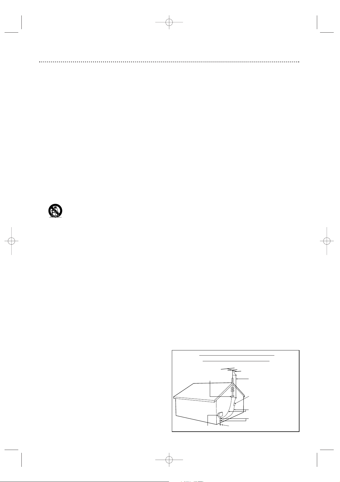
14. Outdoor Antenna Grounding – If an outside antenna or
cable system is connected to the product, be sure the antenna or cable system is grounded so as to provide some protection against voltage surges and built-up static charges.
Article 810 of the National Electrical Code, ANSI/NFPA 70,
provides information with regard to proper grounding of the
mast and supporting structure, grounding of the lead-in wire
to an antenna discharge unit, size of grounding conductors,
location of antenna-discharge unit, connection to grounding
electrodes, and requirements for the grounding electrode.
See figure at right.
15. Lightning – For added protection for this product during a
lightning storm, or when it is left unattended and unused for
long periods of time, unplug it from the wall outlet and disconnect the antenna or cable system.This will prevent damage to the product due to lightning and power-line surges.
16. Power Lines – An outside antenna system should not be
located in the vicinity of overhead power lines or other electric light or power circuits, or where it can fall into such
power lines or circuits.When installing an outside antenna
system, take extreme care to keep it from touching such
power lines or circuits; contact with them might be fatal.
17. Overloading – Do not overload wall outlets, extension
cords, or integral convenience receptacles.This can result in
a risk of fire or electric shock.
18. Object and Liquid Entry – Never push objects of any kind
into this product through openings; they may touch dangerous voltage points or short out parts, resulting in a fire or
electric shock. Never spill liquid of any kind on the product.
19. Servicing – Do not attempt to service this product yourself.
Opening or removing covers may expose you to dangerous
voltage or other hazards. Refer all servicing to qualified service personnel.
20. Damage Requiring Service – Unplug this product from the
wall outlet and refer servicing to qualified service personnel
under the following conditions:
a) When the power supply cord or plug is damaged,
b) If liquid has spilled or objects have fallen into the product,
c) If the product has been exposed to rain or water,
d) If the product does not operate normally by following the
operating instructions.Adjust only those controls covered by
the operating instructions.An improper adjustment of other
controls may result in damage and will often require extensive work by a qualified technician to restore the product to
its normal operation,
e) If the product has been dropped or damaged in any way,
f) When the product exhibits a distinct change in performance.This indicates a need for service.
21. Replacement Parts – When replacement parts are required,
be sure the service technician uses replacement parts specified by the manufacturer or having the same characteristics
as the original part. Unauthorized substitutions may result in
fire, electric shock, or other hazards.
22. Safety Check – Upon completion of any service or repairs
to this product, ask the service technician to perform safety
checks to determine that the product is in proper operating
condition.
23. Wall or Ceiling Mounting – Mount the product to a wall or
ceiling only as recommended by the manufacturer.
24. Heat - Situate this product away from heat sources, such as
radiators, heat registers, stoves, or other products (including
amplifiers) that produce heat.
25. Battery usage CAUTION - To prevent battery leakage that
may result in bodily injury, property damage, or damage to
the unit:
• Install all batteries correctly, with + and - aligned as marked
on the unit.
• Do not mix batteries (old/new,carbon/alkaline, etc.).
• Remove batteries when the unit is not used for a long
time.
Example of Antenna Grounding
per National Electrical Code
E9490UD_EN.qx3 04.8.3 11:54 AM Page 4
GROUND CLAMP
ELECTRIC SERVICE EQUIPMENT
POWER SERVICE GROUNDING ELECTRODE SYSTEM (NEC ART 250, PART H)
ANTENNA LEAD IN WIRE
ANTENNA DISCHARGE UNIT
GROUNDING CONDUCTORS (NEC SECTION 810-21)
GROUND CLAMPS
(NEC SECTION 810-20)
Page 5

Contents 5
General Information
Safety Information . . . . . . . . . . . . . . . . . . . . . . . . . . . . . . .3-4
Contents . . . . . . . . . . . . . . . . . . . . . . . . . . . . . . . . . . . . . . . .5
Introduction . . . . . . . . . . . . . . . . . . . . . . . . . . . . . . . . . . . . .6
Getting Started
Playable Discs . . . . . . . . . . . . . . . . . . . . . . . . . . . . . . . . . . . .7
General Information . . . . . . . . . . . . . . . . . . . . . . . . . . . . . . .8
Hookups . . . . . . . . . . . . . . . . . . . . . . . . . . . . . . . . . . . . . .9-17
Initial Setup . . . . . . . . . . . . . . . . . . . . . . . . . . . . . . . . . . .18-19
Basic Play and Recording
Quick Videotape Playback . . . . . . . . . . . . . . . . . . . . . . . . . .20
Quick Disc Playback . . . . . . . . . . . . . . . . . . . . . . . . . . . . . .21
Quick Disc Recording . . . . . . . . . . . . . . . . . . . . . . . . . . . . .22
Controls
Remote Control . . . . . . . . . . . . . . . . . . . . . . . . . . . . . . .23-24
Display Panel (VCR) . . . . . . . . . . . . . . . . . . . . . . . . . . . . . . .25
Front Panel . . . . . . . . . . . . . . . . . . . . . . . . . . . . . . . . . . . . .26
Rear Panel . . . . . . . . . . . . . . . . . . . . . . . . . . . . . . . . . . . . . .27
Advanced Installation
TV Channel Programming . . . . . . . . . . . . . . . . . . . . . . . . . .28
VCR Plus+
®
Channels . . . . . . . . . . . . . . . . . . . . . . . . . . . . .29
Clock Setting . . . . . . . . . . . . . . . . . . . . . . . . . . . . . . . . .30-31
Disc Menus and Displays
Menu Bars . . . . . . . . . . . . . . . . . . . . . . . . . . . . . . . . . . . . . .32
On-screen Symbols, Status Box . . . . . . . . . . . . . . . . . . . . . .33
Index Picture Screen . . . . . . . . . . . . . . . . . . . . . . . . . . . . . .34
Information Boxes . . . . . . . . . . . . . . . . . . . . . . . . . . . . . . . .35
Disc Playback Features
Title/Disc Menus, Chapter/Track Selection . . . . . . . . . . . . . .36
Audio Language, Subtitles . . . . . . . . . . . . . . . . . . . . . . . . . . .37
Zoom, Camera Angle . . . . . . . . . . . . . . . . . . . . . . . . . . . . . .38
Still Picture/Frame-by-Frame Play, Sound . . . . . . . . . . . . . . .39
Slow Motion, Searching . . . . . . . . . . . . . . . . . . . . . . . . . . . .40
Time Search, Scan . . . . . . . . . . . . . . . . . . . . . . . . . . . . . . . .41
Repeat, Repeat A-B . . . . . . . . . . . . . . . . . . . . . . . . . . . . . . .42
Disc Recording Options
One-Touch Recording . . . . . . . . . . . . . . . . . . . . . . . . . . . . .43
Videotape to DVD Duplication . . . . . . . . . . . . . . . . . . . . . .44
Timer Recording (DVD mode only) . . . . . . . . . . . . . . . . . .45
VCR Plus+
®
Timer Recording (DVD mode only) . . . . . . . . .46
Erasing Timer Recordings . . . . . . . . . . . . . . . . . . . . . . . . . . .47
Error Messages . . . . . . . . . . . . . . . . . . . . . . . . . . . . . . . . . .48
Record One Channel/Watch Another (DVD mode) . . . . . .49
Title Settings Menu . . . . . . . . . . . . . . . . . . . . . . . . . . . . . . .50
Append Recording, Chapter Markers . . . . . . . . . . . . . . . . . .51
Record Settings . . . . . . . . . . . . . . . . . . . . . . . . . . . . . . . . . .52
Disc Editing
Editing: Disc Information Screen . . . . . . . . . . . . . . . . . . . . .53
Editing . . . . . . . . . . . . . . . . . . . . . . . . . . . . . . . . . . . . . . . . .54
Finalize Disc . . . . . . . . . . . . . . . . . . . . . . . . . . . . . . . . . . . . .55
Additional Disc Features and Setup Options
Auto Resume, Playback Control . . . . . . . . . . . . . . . . . . . . .56
Access Control . . . . . . . . . . . . . . . . . . . . . . . . . . . . . . . .57-61
DVD Recorder Features Menu . . . . . . . . . . . . . . . . . . . . . .62
Picture Settings . . . . . . . . . . . . . . . . . . . . . . . . . . . . . . . . . .63
Digital Output . . . . . . . . . . . . . . . . . . . . . . . . . . . . . . . . . . .64
Analog Output . . . . . . . . . . . . . . . . . . . . . . . . . . . . . . . . . . .65
Language Settings . . . . . . . . . . . . . . . . . . . . . . . . . . . . . . . . .66
Night Mode, Remote Control Used . . . . . . . . . . . . . . . . . . .67
VCR Displays
VCR Status Displays . . . . . . . . . . . . . . . . . . . . . . . . . . . . . .68
VCR Recording Options
Videotape Recording . . . . . . . . . . . . . . . . . . . . . . . . . . . . . .69
Record One Channel/Watch Another (VCR) . . . . . . . . . . . .70
One-Touch Recording (VCR) . . . . . . . . . . . . . . . . . . . . . . . .71
Rerecording (Tape Duplication) . . . . . . . . . . . . . . . . . . . . . .72
DVD to Videotape Duplication . . . . . . . . . . . . . . . . . . . . . .73
Ta pe Playback Features
Ta pe Counter . . . . . . . . . . . . . . . . . . . . . . . . . . . . . . . . . . .74
Time Search, Index Search . . . . . . . . . . . . . . . . . . . . . . . . . .75
Special Effects Playback (Videotape) . . . . . . . . . . . . . . . . . . .76
Automatic Operation Features . . . . . . . . . . . . . . . . . . . . . .77
Information You May Need
Glossary . . . . . . . . . . . . . . . . . . . . . . . . . . . . . . . . . . . . .78-79
Helpful Hints . . . . . . . . . . . . . . . . . . . . . . . . . . . . . . . . .80-83
Care and Maintenance . . . . . . . . . . . . . . . . . . . . . . . . . . . . .84
Specifications . . . . . . . . . . . . . . . . . . . . . . . . . . . . . . . . . . . .85
Limited Warranty . . . . . . . . . . . . . . . . . . . . . . . . . . . . . . . . .86
Information Index . . . . . . . . . . . . . . . . . . . . . . . . . . . . . . . .88
E9490UD_EN.qx3 04.8.3 11:54 AM Page 5
Page 6

6 Introduction
Welcome!
Your Magnavox DVD and Video Cassette Recorder records both DVD+RW/DVD+R and videotapes,
but also plays prerecorded videotapes, DVDs and other Disc types.You can record TV programs, edit
camcorder recordings, and quickly access your DVD recordings in the Index Picture Screen.You’ll soon
appreciate the digital picture and sound quality of DVD, DVD+RW, and DVD+R, which will exceed the
quality you have had with videotapes.
Read this manual carefully to understand the latest features,then enjoy your new DVD and Video
Cassette Recorder.
DVD Features
● External Source to DVD+R/DVD+RW
recording
● Fast Forward/Reverse Search
● Index Picture Screen
● NTSC/PAL compatibility
● Paused/Slow/Step-by-Step/Zoomed Play
● Progressive Scan compatibility
● Repeat and Repeat A-B playback
● Time Search
● Timer Recording
● VCR Plus+ Programming
VCR Features
● Automatic Head Cleaner
● 19 Micron head
● Searching:Time, Index, Forward, and Reverse
● Slow Motion
● Still Picture
● Ta pe Counter
● Tracking Adjustment
DVD/VCR Features
● Channel Setup
● DVD to Videotape Duplication
● English, French, and Spanish displays
● Multi-Channel TV Sound
● OTR (One-Touch Recording)
● Videotape to DVD Duplication
Package Contents
● DVD and Video Cassette Recorder
● Remote control with two AA batteries
● One RF coaxial cable (black with silver tip,
with single prong in center of tip)
● One set of Audio (red and white tips) and
Video (yellow tips) cables
● This owner’s manual, a Quick-Use Guide, and
registration materials
Environmental Information
Your system has materials that can be recycled and reused if disassembled by a specialized company.
Please observe the local regulations regarding the disposal of packaging materials, exhausted batteries,
and old equipment.
Safety Information
● Do not expose the Recorder to excessive moisture, rain, sand, or heat sources.
● Place the Recorder on a firm, flat surface.
● Keep the Recorder away from domestic heating equipment and direct sunlight.
● When placing the Recorder in a cabinet, allow about one inch of space all around the Recorder for
ventilation.
Manufactured under license from Dolby Laboratories.“Dolby,” “Pro Logic,” and the double-D symbol are trademarks of Dolby
Laboratories. Confidential unpublished works. Copyright 1992-1999 Dolby Laboratories. All rights reserved.
VCR Plus+ and PlusCode are registered trademarks of the Gemstar Development Corporation.The VCR Plus+ system is manufactured under license from Gemstar Development Corporation.
Copyright 2004 Philips Consumer Electronics.
E9490UD_EN.qx3 04.8.3 11:54 AM Page 6
Page 7
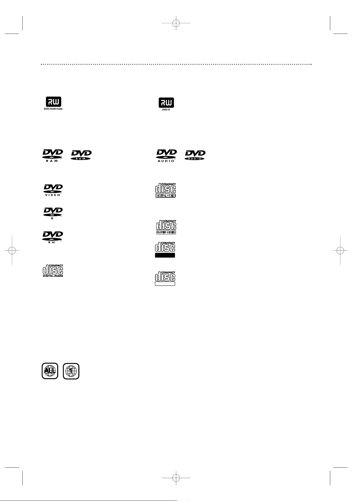
DVD-RAM DVD-Audio
Look for these logos on your Discs to determine whether the Disc will or will not play or record on
the Magnavox DVD and Video Cassette Recorder.
Playable Discs 7
DVD Region Codes and Color Systems
DVDs must meet the requirements for Region Codes and Color Systems before you can use them
with the Recorder. DVDs must be labelled for ALL regions or for Region 1 in order to play on this
DVD Recorder.You cannot play Discs that are labeled for other regions.These symbols must appear on
your DVDs,or you cannot play the DVD in this Recorder. These symbols might also appear on the
Disc’s case or packaging.
The number inside the globe refers to a region of the world. Region 1 represents the United States,
Canada, upper regions of North America, Bermuda, the U.S.Virgin Islands, and small regions near
Australia.
Furthermore, recordings are made according to different color systems throughout the world.The
most common color systems are NTSC, which is used primarily in the United States and North
America, PAL, and SECAM.
This Recorder is compatible with NTSC and PAL. Make sure the Discs you play were recorded in
NTSC or PAL.The color system of the DVD may appear on the DVD or its case.
However, when playing a PAL Disc, the Recorder must be connected to a PAL-compatible TV using
either the S-VIDEO or COMPONENT VIDEO (Y P
B PR) jacks of the Recorder.The Recorder’s VIDEO
jack does not send a clear PAL signal. If a PAL Disc is copy-protected, the picture may not be correct if
you are using the COMPONENT VIDEO (Y P
B PR) jacks.
Discs for Playing Only
DVD (Digital Video Disc)
DVD-R (DVD-Recordable)
You cannot record on these Discs
using the Magnavox Recorder.
DVD-RW (DVD-Rewritable)
You cannot record on these Discs
using the Magnavox Recorder. These
Discs play only if recorded in video
mode and finalized.
Audio CD
(Compact Disc Digital Audio)
Video CD (VCD)
Similar to DVDs, these Discs hold less
material. For example, a two-hour
movie will fit on one DVD, but may
take two VCDs.
Super Video CD (SVCD)
CD-R (CD-Recordable)
Only audio and MP3 contents will play.
CD-RW (CD-Rewritable)
The Disc must be finalized (on your
computer or audio recorder) before
playing on the Magnavox Recorder.
Only audio and MP3 contents will play.
Discs for Recording and Playing
DVD+RW (Digital Video Disc
+ Rewritable): These Discs can be
recorded on repeatedly. Recordings
can be erased, then you can record
again on the same Disc.
DVD+R (Digital Video Disc
+ Recordable): These Discs can be
recorded only once.After you finalize
a DVD+R, you cannot record on it or
edit it any more.
Discs Unsuitable for Recording or Playing
E9490UD_EN.qx3 04.8.3 11:55 AM Page 7
Recordable
ReWritable
Page 8

8 General Information
Battery Installation
1
Remove the battery compartment lid on the rear of the
remote control by pressing in the tab, then lifting off the lid.
2
Place two AA batteries inside the battery compartment
with their +and –ends aligned as indicated. Do not mix old
and new batteries or different types of batteries (standard, alkaline,
etc.).
3
Replace the battery compartment lid. You will hear it click
into place.
Using the Remote Control
Unless stated otherwise, the remote control can operate all the features of
the Recorder. Always point the remote control directly at the remote sensor on the front of the Recorder, not the TV.
See page 26.
Make sure there are no barriers between the remote and the Recorder.
DVD Disc Menus...
Some explanations in this manual describe the DVD Disc Menus,which
vary among DVDs. Movie producers set these menus, and not all DVDs
have menus. But, if the DVD has a menu, access it by pressing the DISC
MENU button on the remote control. See page 36.
Recorder Menus...
Some instructions explain how to use the Recorder’s System Menu or
Menu Bars to set up features of the Recorder or the Disc.You get to the
System Menu by pressing SYSTEM MENU on the remote control. See page
32. Even if a feature is set up in the Recorder’s menu, it will not be available
if the current Disc does not include that feature.
Upgrades
If a prerecorded (store purchased) DVD does not play properly, please contact Magnavox for assistance. Due to the inconsistency of Disc formats provided by various Disc manufacturers, your Recorder may require a free
playability enhancement or upgrade.As DVD technology has advanced,
these enhancements have become both common and easy to complete.
Available Disc Features...
Features in this manual may not be available on every Disc. If the feature is
not available, you cannot use the Recorder to make it available.An “X” will
appear in the top left corner of the TV screen if you try to access a feature
that is not available on the current Disc. Or, try stopping or starting play,
then try the feature again. (Some features are only available during play,
while others are accessible only when play is stopped.)
1
2
3
E9490UD_EN.qx3 04.8.3 11:55 AM Page 8
Page 9

Hookups 9
Determining the best possible connection...
Your existing equipment, especially your TV, will determine your connection.These
guidelines describe which options provide the best picture and sound quality.
★★★★ Component Video provides the best picture quality. Progressive Scan
Component Video has the highest quality, but use it only if the TV has
Progressive Scan. See pages 12 and 63.
★★★ S-Video provides excellent picture quality. See page 13.
★★ Composite Video (a yellow Video jack) provides good picture quality.
See page 14.
★★ Your TV may have only an RF-style jack, usually labeled
Antenna In or 75 ohm.
This may be the jack to which you have connected your Antenna or Cable TV signal already.You can use an RF
coaxial cable for a simple connection. See page 10.
★★★★ Digital audio connections provide the clearest sound. Connect the
Recorder’s COAXIAL DIGITAL AUDIO OUT jack to your Stereo for
the best sound quality. See page 16.
★★★ For the most common audio connection, connect the Recorder’s
white/red AUDIO OUT L/R (left/right) jacks to the Audio In jacks of
your Stereo or TV. See pages 12-15.
Before you begin...
● Refer to the manuals of your TV,Stereo, Cable Box, or other equipment as
necessary. Note the jacks and connectors on the other equipment. Determine
how to choose different Audio and Video In channels on your other equipment
so you can see and hear the Recorder on the TV, Stereo, etc.
● Disconnect all equipment from the power outlets. Connect the equipment to
the power outlets only after you have finished hooking up everything. Never
make or change connections with equipment connected to the power outlet.
Remember...
● Set the TV to the correct Video In channel or channel 3.
This is channel 3 only if you connect the Recorder directly to a TV as
shown on page 10.
Otherwise,Video In channels may be called AUX or AUXILIARY IN,
AUDIO/VIDEO or A/V IN, EXT1 or EXT2 or External In, etc.These
channels often are near TV channel zero (0). Or,your TV remote con-
trol may have a button or switch that lets you choose the Video In channel
directly. See your TV manual for details. Or, go to your lowest TV channel and
change channels down until you see the DVD background picture on the TV
screen.
● Connect the Recorder directly to the TV.For example, do not connect the
Recorder to another VCR, then connect the VCR to a TV.Your VCR may have
the copy protection system, which may distort the picture and sound of a Disc
or Videocassette playing on the Recorder.
● Set the Stereo to the correct channel or “source” mode.
● Do not connect the Recorder’s AUDIO OUT jacks to the PHONO IN jack of
your Stereo.
● You only need one audio connection and one video connection between the
Recorder and your TV (or TV and Stereo).You will not use all the jacks on the
Recorder.
● You can use the Recorder to preserve your memories by copying a
videotape to a DVD+R or DVD+RW. Special connections may be
needed between the Recorder and your camcorder or VCR, which
will play the existing videotape into the Recorder for recording. See
pages 17 and 44 for details and options.
● To use the DVD or VCR features of this Recorder, you must include a
connection with the supplied yellow video cable and red/white audio
cables or with the supplied RF coaxial cable. See pages 10 and 14.
Once you determine the option that best fits with your existing
equipment, find your choice on pages 10-16. Follow the steps for the
hookup you chose.
When you finish your connections and turn on the Recorder for the
first time, complete the Initial Setup.This sets up TV channels, menu
languages, and other features. Go to page 18 to do the Initial Setup.
E9490UD_EN.qx3 04.8.3 11:55 AM Page 9
Page 10
10 Hookups (cont’d)
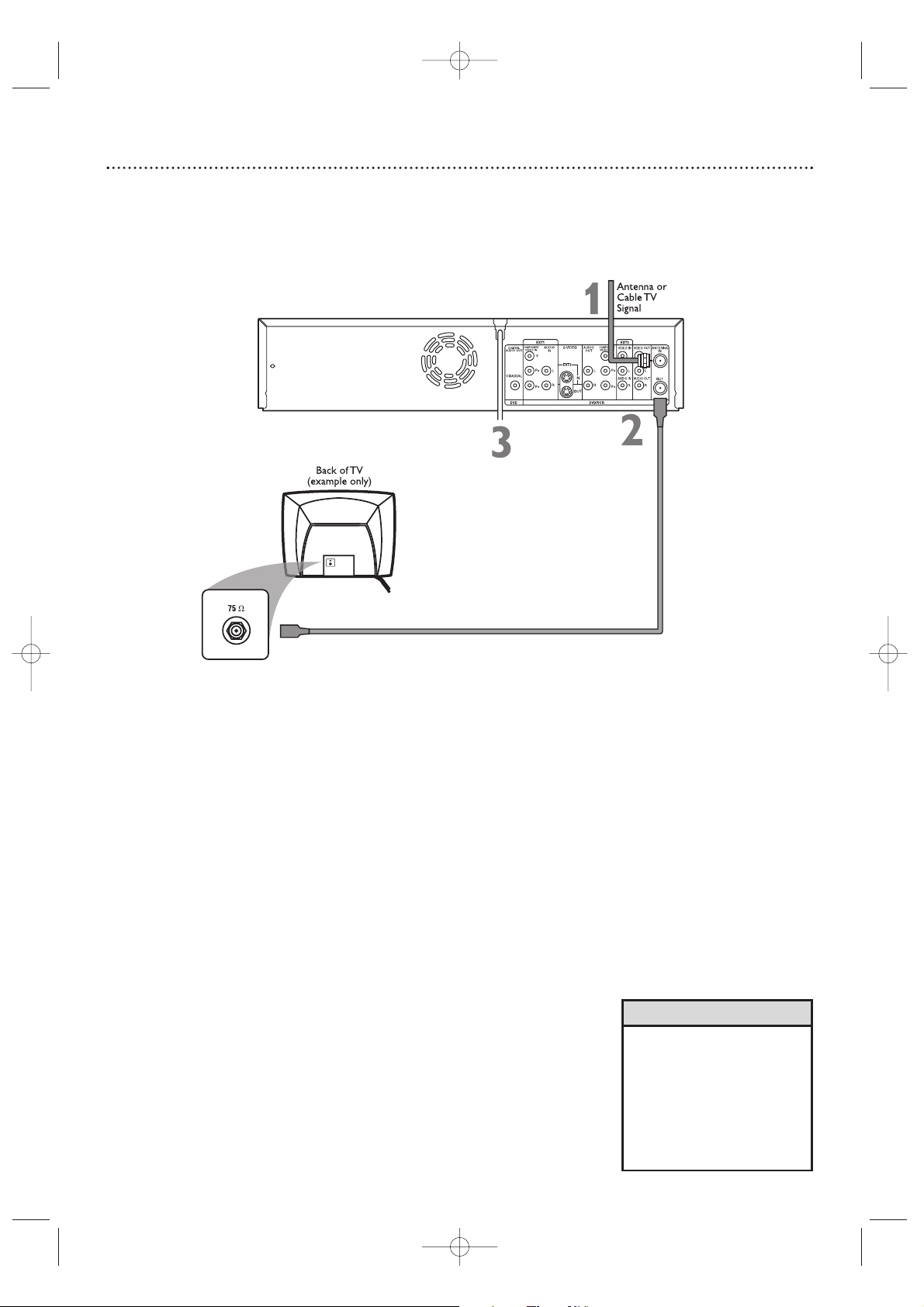
Connecting to a TV Only
TV has only an Antenna In jack
1
Connect your Antenna or Cable TV signal to the ANTENNA IN jack
on the rear of the Recorder. Your antenna or Cable TV signal may have
been connected to your TV. If so, disconnect it from the TV and connect it to
the Recorder’s ANTENNA IN jack.
2
Connect the supplied RF coaxial cable to the (ANTENNA) OUT
jack on the rear of the Recorder. Connect the other end of the
same RF coaxial cable to the Antenna In jack on your TV. Your TV’s
Antenna In jack may be labelled RF In,Antenna In, or 75 ohm. Check your TV’s
manual for details.
3
Connect the power cords of the Recorder and the TV to a power
outlet.
4
Press STANDBY-ON yyto turn on the Recorder.
5
Turn on the TV power. Set it to channel 3. You should see the DVD
background picture or the Initial Setup screen on the TV.The Initial Setup screen
will appear the first time you turn on the Recorder. Go to page 18 to continue.
If channel 3 is already occupied, you may need to use channel 4 as your
Recorder's output channel instead.To change the output channel to channel 4,
press STANDBY-ON y to turn off the Recorder. Press DVD on the
remote.Then press and hold the Number 4 button on the remote for several
seconds until you see "C04" on the display panel. Now the Recorder's output
channel is set to channel 4. Set your TV to channel 4. The Initial Setup screen
should appear. (To go back to using channel 3 at the TV, press and hold the
Number 3 button on the remote instead.)
•
If “IS TV ON? C03” appears on
the display panel, you need to
turn on your TV and set it to
channel 3.This is part of the
Initial Setup.You cannot see the
Initial Setup screens until you
turn on the TV and have it on
the correct Video In channel
(channel 3 for this connection).
Helpful Hint
*This enables use of both VCR and DVD modes.
E9490UD_EN.qx3 04.8.3 11:55 AM Page 10
Page 11
Hookups (cont’d) 11
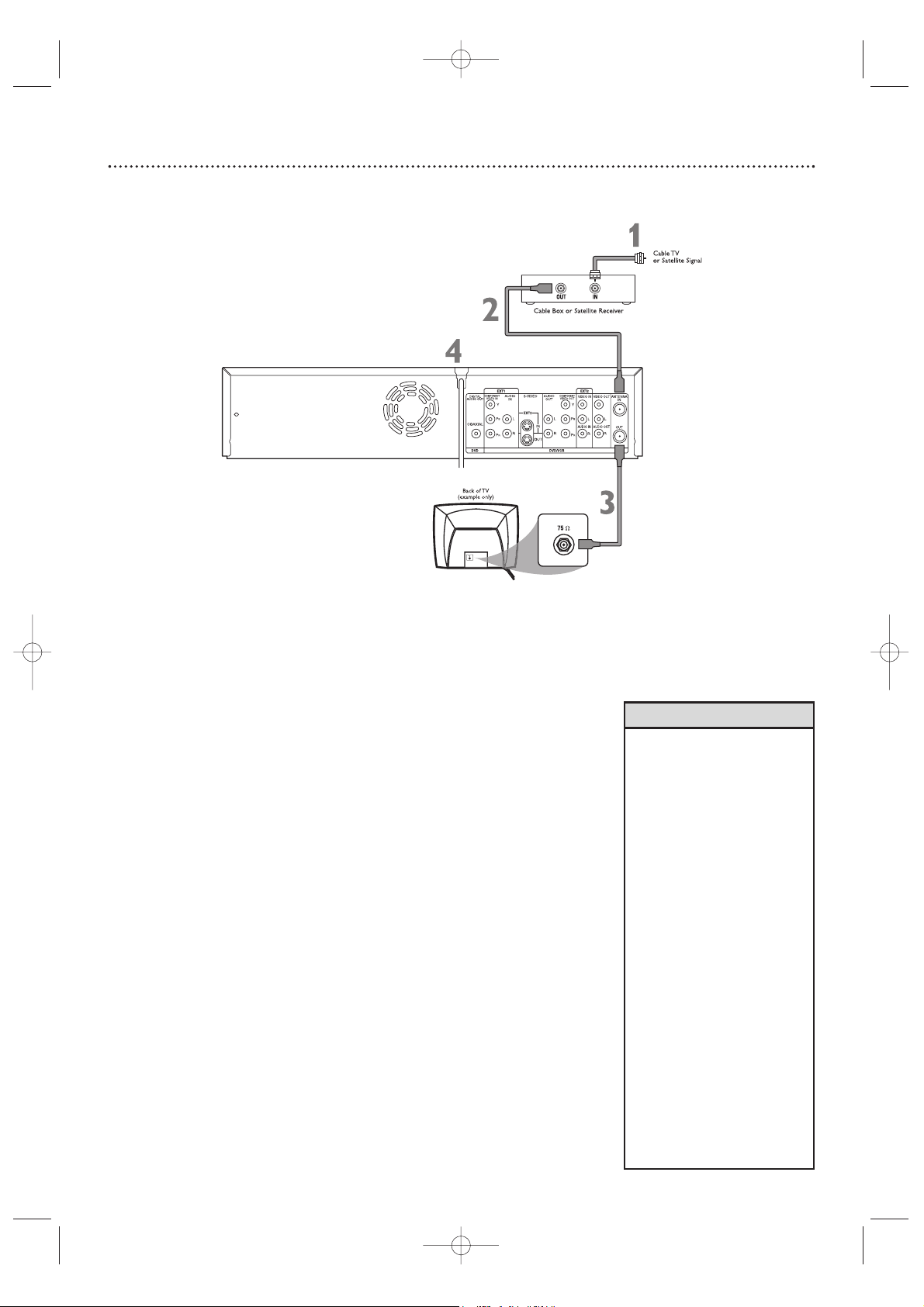
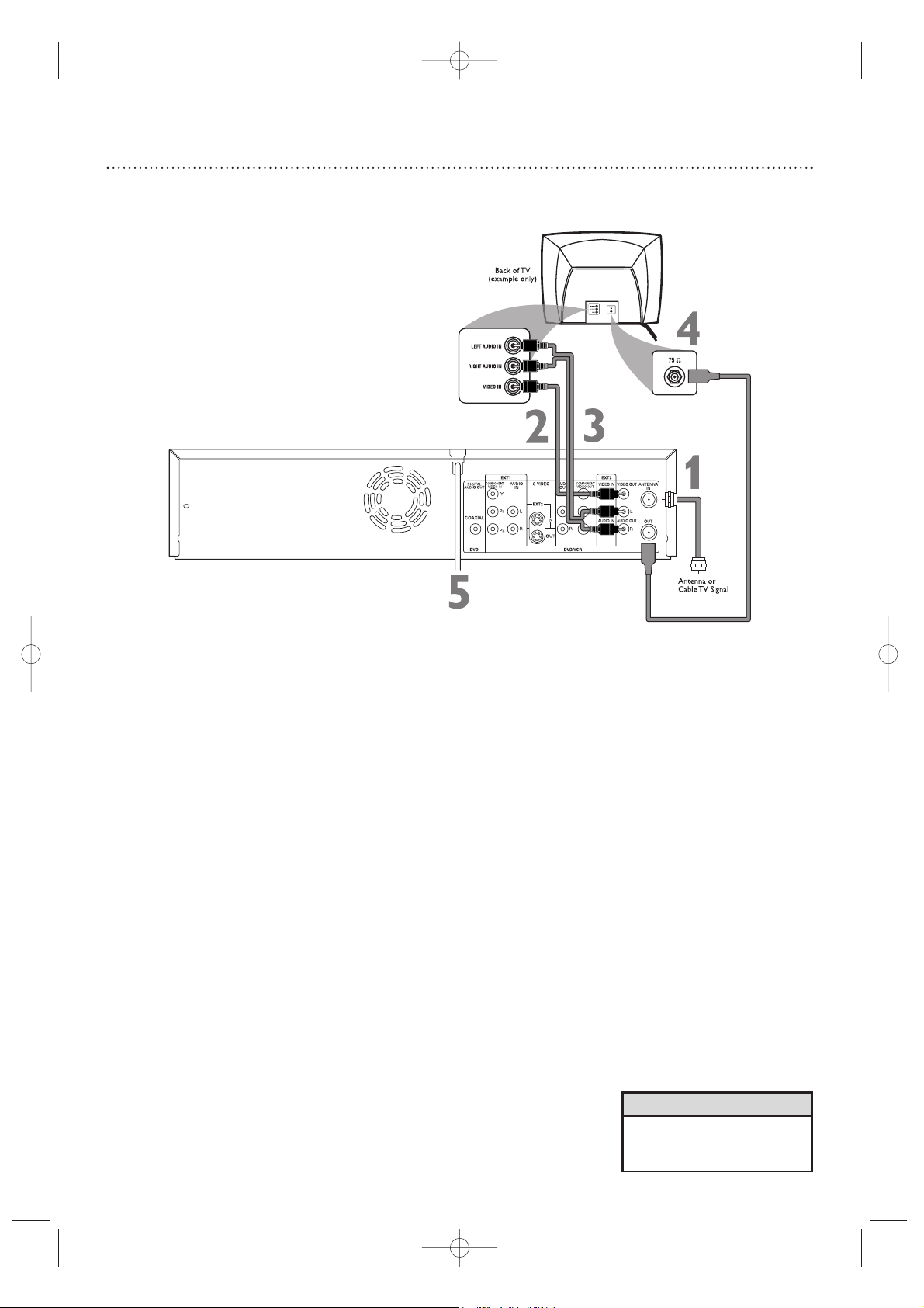
Connecting to a TV and a Cable Box or Satellite Receiver
1
Connect your Satellite or Cable TV signal to the ANTENNA IN jack
on your Cable Box/Satellite Receiver.
2
If your Cable Box/Satellite Receiver has a single ANTENNA OUT or
TO TV jack: Connect the supplied RF coaxial cable to the ANTENNA OUT/TO TV jack of the Cable Box/Satellite Receiver and to the
ANTENNA IN jack on the rear of the Recorder.
If your Cable Box/Satellite Receiver has AUDIO/VIDEO OUT jacks: Connect them to
the Recorder’s EXT 2 VIDEO IN and AUDIO IN jacks.These jacks are red and white
(AUDIO) and yellow (VIDEO). Use the supplied audio and video cables, which have
red/white/yellow markings.
3
Connect another RF coaxial cable to the Recorder’s (ANTENNA)
OUT jack and to the ANTENNA IN or RF IN jack on your TV. Your
TV’s Antenna In jack may be labelled RF In or 75 ohm. Check your TV manual
for details. Or, use an Audio/Video connection between the Recorder and the
TV. See pages 12-15.
4
Connect the power cords of the Recorder, Cable Box/Satellite
Receiver, and TV to a power outlet.
5
Press STANDBY/ON yyto turn on the Recorder. Set the Recorder
to channel 3 or 4 (your Cable Box/Satellite Receiver’s output channel) if you used an RF coaxial cable to connect the Cable
Box/Satellite Receiver to the Recorder.
Set the Recorder to EXT 2 if you used those jacks on the Recorder
to connect to the Cable Box/Satellite Receiver.
6
Tu rn on the TV and the Cable Box/Satellite Receiver.
Set the TV to channel 3 to receive the picture from the Recorder (if
you used the RF coaxial cable as shown for step 3).
You should see the DVD background picture or the Initial Setup screen on the
TV. The Initial Setup screen will appear the first time you turn on the Recorder. Go to
page 18 to continue.
•To watch TV, put the
Recorder in Monitor mode
and on channel 3 or 4. (Press
MONITOR on the
Recorder’s remote.) Change
TV channels at your Cable
Box or Satellite Receiver.
• If “IS TV ON? C03” appears on
the display panel, you need to
turn on your TV and set it to
channel 3.You cannot see the
Initial Setup screens until you
turn on the TV and have it on
the correct Video In channel.
• If channel 3 is already occupied,
you may need to use channel 4
as your Recorder's output channel instead.To change the output
channel to channel 4, press
STANDBY-ONy to turn off the
Recorder. Press DVD on the
remote.Then press and hold the
Number 4 button on the remote
for several seconds until you see
"C04" on the display panel. Now
the Recorder's output channel is
set to channel 4. Set your TV to
channel 4. The Initial Setup
screen should appear.
Helpful Hints
E9490UD_EN_v1_film.qx3 04.8.4 3:56 PM Page 11
Page 12
12 Hookups (cont’d)
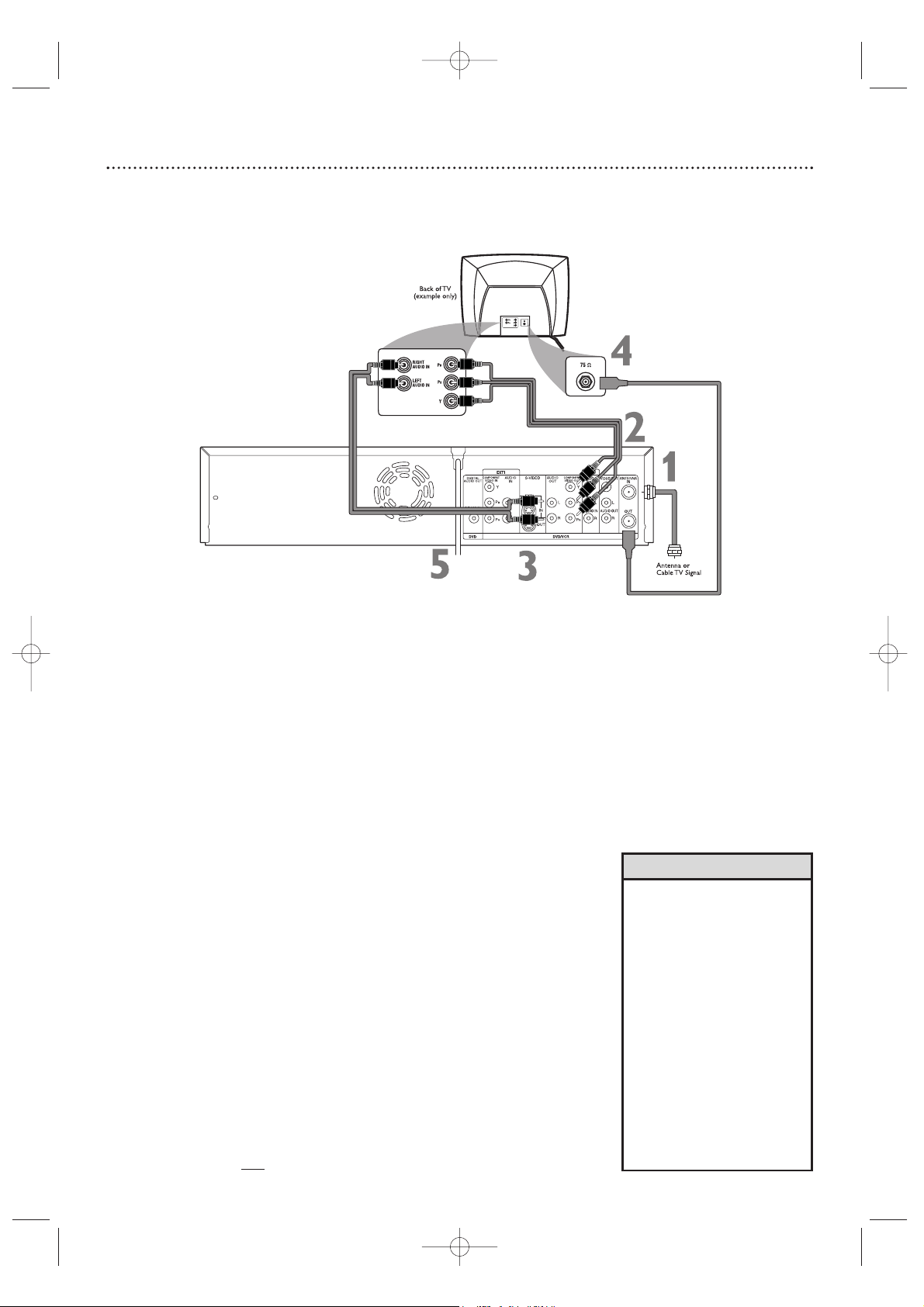
Connecting to a TV Only
TV has Component Video In Jacks
1
Connect your Antenna or Cable TV signal to the ANTENNA IN jack
on the rear of the Recorder.
2
Connect the Recorder’s COMPONENT VIDEO OUT (Y PB PR)
jacks to the TV’s COMPONENT VIDEO IN jacks. Use component
video cable (not supplied), which has red, blue, and green markings.Match the
cable colors to the jack colors.
3
Connect the Recorder’s white/red AUDIO OUT L/R (left/right) jacks
to the TV’s left/right AUDIO IN jacks. Use the supplied two-strand audio
cable, which has red and white markings. Match cable colors to jack colors.
4
Connect the supplied RF coaxial cable to the Recorder’s (ANTENNA) OUT jack and to the Antenna In jack on your TV. Your TV’s
Antenna In jack may be labelled RF In,Antenna In, or 75 ohm. Check your TV’s
manual for details.
5
Connect the power cords of the Recorder and the TV to a power
outlet.
6
Press STANDBY-ON yyto turn on the Recorder. If “IS TV ON? CO3”
appears on the display panel,you need to turn on your TV and set it to the
correct Component Video In channel. (See next step.) You cannot see the
Initial Setup screens until you turn on the TV and have it on the correct
Component Video In channel.
7
Turn on the TV power. Set the TV to the Component Video In channel. It is not channel 3 or 4 when you use Component Video. See your TV
owner’s manual for details. Your TV remote may have a button or switch that
selects the Component Video In channel. Or, go to your lowest TV channel
and change channels down until you see the DVD background picture or
Initial Setup screen on the TV. The Initial Setup screen will appear the first time
you turn on the Recorder. Go to page 18 to continue.
NOTE:When using the Component Video jacks, make sure Component
video output is set to Interlaced. Set Component video output to
Progressive Scan onl
y if your TV has Progressive Scan.
See page 63.
•
If your TV has Progressive
Scan,
connect the Recorder’s
COMPONENT VIDEO OUT (Y
PB PR) jacks to the TV’s
Progressive Scan In jacks
instead. Progressive Scan produces a clearer picture by doubling the number of visible picture lines per field, providing a
jitter-free, sharp, quiet picture.
Check your TV manual for
details.
Set the Recorder’s Video
output to Progressive Scan.
See page 63.
• On the TV, the Component Video
In jacks may be labeled YUV or
Pr/Cr Pb/Cb Y and may be
green, blue, and red.
Helpful Hints
E9490UD_EN.qx3 04.8.3 11:55 AM Page 12
Page 13
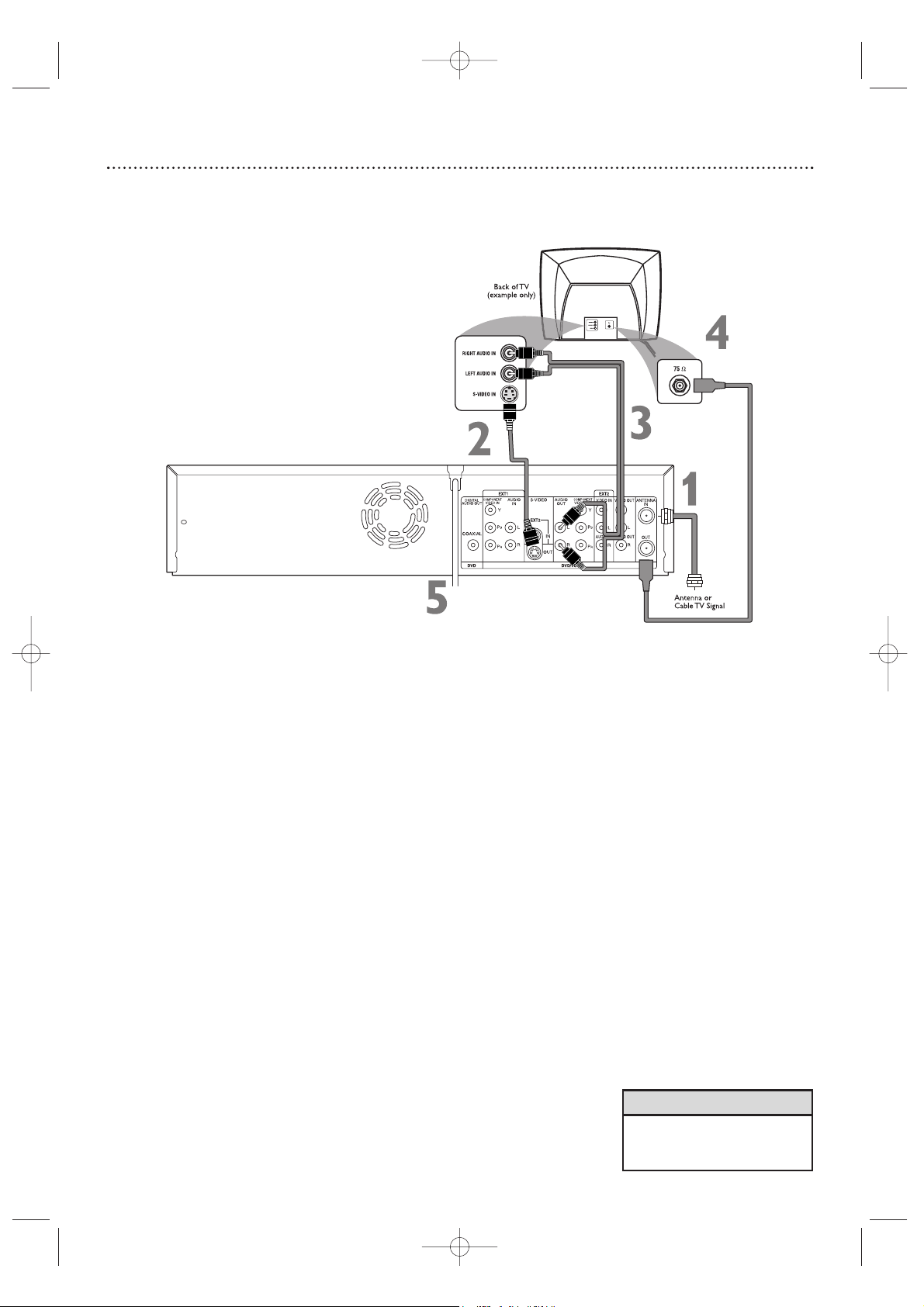
1
Connect your Antenna or Cable TV signal to the ANTENNA IN jack
on the rear of the Recorder.
2
Connect an S-Video cable (not supplied) to the Recorder’s S-VIDEO
OUT jack and to the TV’s S-VIDEO In jack.
3
Connect the supplied audio cable to the Recorder’s white/red
AUDIO OUT L/R (left/right) jacks and to the left/right AUDIO IN
jacks on the TV. Match the cable colors to the jack colors.
4
Connect the supplied RF coaxial cable to the (ANTENNA) OUT
jack on the rear of the Recorder. Connect the other end of the
same RF coaxial cable to the Antenna In jack on your TV. Your TV’s
Antenna In jack may be labelled RF In,Antenna In, or 75 ohm. Check your TV’s
manual for details.
5
Connect the power cords of the Recorder and the TV to a power
outlet.
6
Press STANDBY-ON yyto turn on the Recorder. If “IS TV ON? C03”
appears on the display panel,you need to turn on your TV and set it to the SVideo In channel. (See next step.) You cannot see the Initial Setup screens until
you turn on the TV and have it on the correct S-Video In channel.
7
Turn on the TV power. Set the TV to the S-Video In channel. This is
not channel 3 or 4 when you are using S-Video. Your TV remote may have a
button or switch that selects the S-Video In channel. Or, go to your lowest TV
channel and change channels down until you see the DVD background picture
or Initial Setup screen on the TV. The Initial Setup screen will appear the first time
you turn on the Recorder. Go to page 18 to continue.
Hookups (cont’d) 13
Connecting to a TV Only
TV has an S-Video In Jack
• On the TV, the S-Video In jack
may be labeled Y/C , S-Video, or
S-VHS (super video).
Helpful Hint
E9490UD_EN.qx3 04.8.3 11:55 AM Page 13
Page 14
14 Hookups (cont’d)
Connecting to a TV Only
TV has a yellow Video In jack
1
Connect your Antenna or Cable TV signal to the ANTENNA IN jack
on the rear of the Recorder.
2
Connect the Recorder’s yellow VIDEO OUT jack to your TV’s
VIDEO IN jack. Use the supplied video cable that has yellow markings.
3
Connect the supplied audio cable to the Recorder’s white/red
AUDIO OUT L/R (left/right) jacks and to the left/right AUDIO IN
jacks on your TV. The supplied audio cable has red and white markings.
Match the cable colors to the jack colors.
4
Connect the supplied RF coaxial cable to the (ANTENNA) OUT
jack on the rear of the Recorder. Connect the other end of the
same RF coaxial cable to the Antenna In jack on your TV. Your TV’s
Antenna In jack may be labelled RF In,Antenna In, or 75 ohm. Check your TV
manual for details.
5
Connect the power cords of the Recorder and the TV to a power
outlet.
6
Press STANDBY-ON yyto turn on the Recorder.
If “IS TV ON? CO3” appears on the display panel, you need to turn on your
TV and set it to the correct Video In channel. (See next step.) You cannot see
the Initial Setup screens until you turn on the TV and have it on the correct
Video In channel.
7
Turn on the TV power. Set the TV to the correct Audio/Video In
channel. Such channels may be called AUX or AUXILIARY IN,
AUDIO/VIDEO or A/V IN, EXT1 or EXT2 or External In, etc.
This is not
channel 3 or 4. See your TV manual. Your TV remote may have a button or
switch that selects the Video In channel. Or,go to your lowest TV channel and
change channels down until you see the DVD background picture or Initial
Setup screen.
The Initial Setup screen will appear the first time you turn on the
Recorder. Go to page 18 to continue.
• The TV’s Video In jack is usually
yellow. It may be labeled video,
CVBS, composite, or baseband.
Helpful Hint
E9490UD_EN.qx3 04.8.3 11:55 AM Page 14
Page 15
Hookups (cont’d) 15
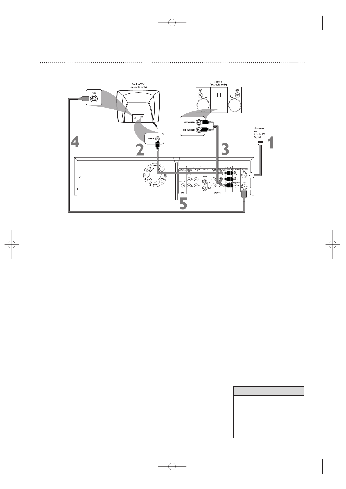
Connecting to a TV and a Stereo
1
Connect your Antenna or Cable TV signal to the ANTENNA IN jack
on the rear of the Recorder.
2
Connect the Recorder’s yellow VIDEO OUT jack to your TV’s
VIDEO IN jack. Use the supplied video cable that has yellow markings.
3
Connect the supplied audio cable to the Recorder’s white/red
AUDIO OUT L/R (left/right) jacks and to the left/right AUDIO IN
jacks on the Stereo. The audio cable has red and white markings. Match the
cable colors to the jack colors.
4
Connect the supplied RF coaxial cable to the (ANTENNA) OUT
jack on the rear of the Recorder. Connect the other end of the
same RF coaxial cable to the Antenna In jack on your TV.
Your TV’s
Antenna In jack may be labelled RF In,Antenna In, or 75 ohm. Check your TV
manual for details.
5
Connect the power cords of the Recorder, Stereo, and TV to a
power outlet.
6
Turn on the Stereo and set it to the correct Audio In channel or
sound source. Refer to the Stereo owner’s manual.
7
Press STANDBY-ON yyto turn on the Recorder.
If “IS TV ON? CO3” appears on the display panel, you need to turn on your
TV and set it to the correct Video In channel. (See next step.) You cannot see
the Initial Setup screens until you turn on the TV and have it on the correct
Video In channel.
8
Turn on the TV power. Set the TV to the correct Video In channel.
Such channels may be called AUX or AUXILIARY IN, AUDIO/VIDEO or
A/V IN, EXT1 or EXT2 or External In, etc.
This is not channel 3 or 4 if you
are using the connection shown. See your TV manual. Your TV remote may
have a button or switch that selects the Video In channel. Or, go to your lowest TV channel and change channels down until you see the DVD background
picture or Initial Setup screen.
The Initial Setup screen will appear the first time you turn on the Recorder.Go to
page 18 to continue.
• Set Analog output accordingly.
See page 65.
•To use Component Video or SVideo instead, see pages 12-13.
You only need one video connection. Choose the correct
Video In channel at the TV.
Helpful Hints
E9490UD_EN.qx3 04.8.3 11:55 AM Page 15
Page 16
16 Hookups (cont’d)
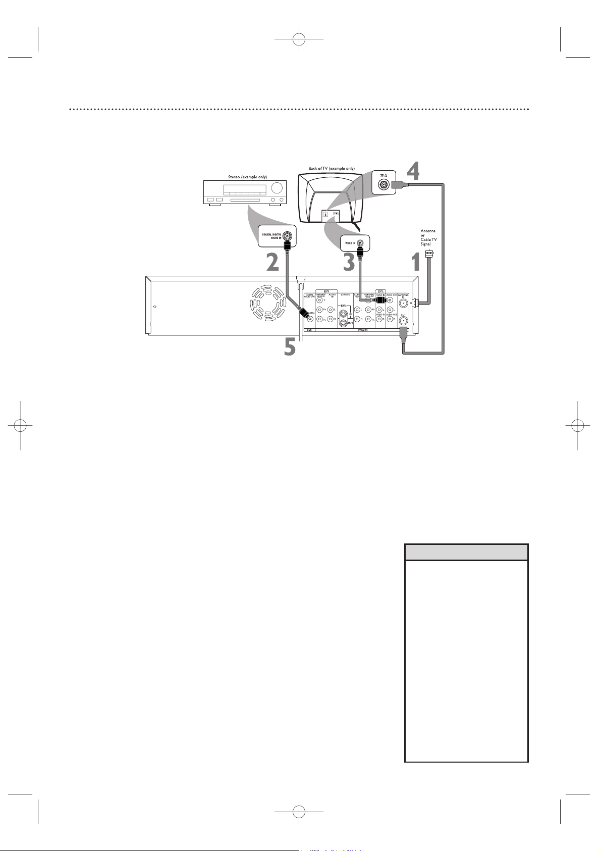
Connecting to a TV and a Digital Stereo
(Stereo has Dolby DigitalTMor MPEG2)
1
Connect your Antenna or Cable TV signal to the ANTENNA IN jack
on the rear of the Recorder.
2
Connect the Recorder’s COAXIAL DIGITAL AUDIO OUT jack to
your Stereo’s COAXIAL DIGITAL AUDIO IN jack. Use a coaxial digi-
tal audio cable (not supplied).
3
Connect the Recorder’s yellow VIDEO OUT jack to your TV’s
VIDEO IN jack. Use the supplied video cable that has yellow markings.
4
Connect the supplied RF coaxial cable to the (ANTENNA) OUT
jack on the rear of the Recorder. Connect the other end of the
same RF coaxial cable to the Antenna In jack on your TV. Your TV’s
Antenna In jack may be labelled RF In,Antenna In, or 75 ohm. Check your TV
manual for details.
5
Connect the power cords of the Recorder, Stereo, and TV to a
power outlet.
6
Turn on the Stereo power and set your Stereo to the correct Digital
Audio In channel or sound source. Refer to the Stereo owner’s manual.
7
Press STANDBY-ON yyto turn on the Recorder.
If “IS TV ON? CO3” appears on the display panel, you need to turn on your
TV and set it to the correct Video In channel. (See next step.) You cannot see
the Initial Setup screens until you turn on the TV and have it on the correct
Video In channel.
8
Turn on the TV power. Set the TV to the correct Video In channel.
This is not channel 3 or 4 if you are using the connection shown. See your TV
manual.Your TV remote may have a button or switch that selects the Video In
channel. Or,go to your lowest TV channel and change channels down until you
see the DVD background picture or Initial Setup screen on the TV. The Initial
Setup screen will appear the first time you turn on the Recorder.Go to page 18 to
continue.
• Digital audio is only available for
the Discs you play.You still must
make a stereo audio connection
(red/white cables) or the RF coaxial connection to have sound at
the VCR.
• Set Digital output accordingly. See
page 64.
If the Digital output setting does not match your Stereo’s
capabilities, the Stereo may produce a strong, distorted sound or
no sound at all.
•Your Stereo must support Dolby
Digital
TM
or MPEG2. Check the
Stereo’s manual.
•To use Component Video or SVideo instead, see pages 12-13.
You only need one video connection. Choose the correct
Video In channel at the TV.
Helpful Hints
E9490UD_EN.qx3 04.8.3 11:55 AM Page 16
Page 17
Hookups (cont’d) 17
Connecting to Other Equipment for Dubbing
• Most prerecorded videotapes
and DVDs are copy protected. If
you try to copy them, the
Recorder display may show
“COPY PROTECT.”
• If the Recorder’s display shows
“NO SIGNAL,” adjust the tracking or play the videotape on the
VCR/Camcorder/External VCR.
See your VCR/Camcorder manual to improve the quality of
tape play.
• Do not connect a Progressive
Scan video source (such as a
DVD Player) to the EXT 1
COMPONENT VIDEO IN jacks.
The Recorder cannot receive
Progressive Scan video.
Helpful Hints
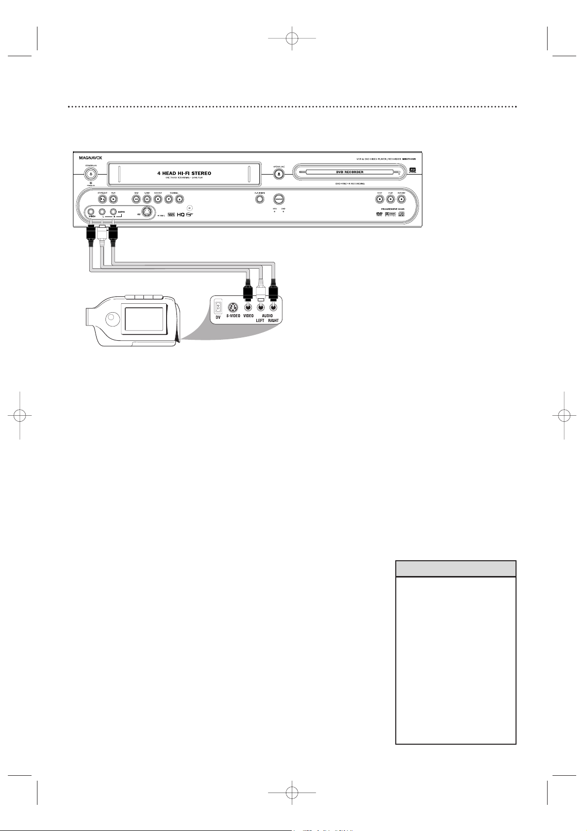
You can connect a VCR, Camcorder, or DVD Player
to the COMPONENT VIDEO IN (Y P
B PR), S-VIDEO
IN, VIDEO IN, and AUDIO IN jacks on the rear panel
or to the VIDEO IN,AUDIO IN, or SV (S-Video) IN
jacks on the front panel.
A sample connection with a Camcorder is shown here,
using the AUDIO/VIDEO IN jacks on the front of the
Recorder. These jacks are the most easily accessible.
Other equipment will connect similarly, but this is a
common connection possibility.
Use the IN jacks on the rear of the Recorder for permanent connections.That will hide the cables from view.
1
Connect the Recorder directly to your TV.
Choose a connection from pages 10-16.
2
To access the AUDIO/VIDEO IN jacks on the front of the
Recorder, flip down the door that covers the jacks.
3
Connect a video cable to the VIDEO OUT jack of your
Camcorder and to the yellow VIDEO IN jack on the front of the
Recorder. Use an RCA-style video cable, which is usually marked with
yellow. (One video cable is supplied with the Recorder.)
4
Connect audio cables to the AUDIO OUT jacks of your
Camcorder and to the red and white AUDIO IN jacks on the
front of the Recorder. One set of audio cables is supplied with the
Recorder. Most audio cables are red and white. Match the cable colors to
the jack colors.
5
When all connections are complete, connect all the equipment to
power. Turn on all the equipment.
Press STANDBY-ON y on the
front of the Recorder to turn it on.
6
Set your TV to the correct Video In channel. This will be channel 3
or 4 or a specific Video In channel, depending on your connection between
the Recorder and the TV. Refer to the connection details on pages 10-16. Or,
simply go to channel 5 on your TV, then change channels down until you
see the Recorder’s logo on the TV screen.
The Initial Setup screen will appear
the first time you turn on the Recorder. Go to page 18 to continue.
7
To watch or record the material playing on the other equipment, press
MONITOR to put the Recorder in Monitor mode. Press KKor
LL
to select CAM1 at the Recorder. This is located after your highest TV
channel and before your lowest TV channel. Choose CAM1 if you used the
connection shown on this page (with the jacks on the front of the
Recorder). If you use the EXT 1 or EXT 2 jacks on the rear of the
Recorder instead, choose channel EXT 1 or EXT 2. Choose the channel
that matches the jacks to which you connected the other equipment.
Start playing the material by pressing PLAY on the other equipment. Press RECORD I on the front of the Recorder to start
recording on a DVD+R/DVD+RW or a videotape. (See page 44 for
DVD+R or DVD+RW recording.)
E9490UD_EN.qx3 04.8.3 11:55 AM Page 17
Page 18
18 Initial Setup
Initial Setup screens will appear the very first time you turn on the Recorder.
These on-screen messages and menus will help you set up Recorder features
quickly, including TV channels and language options.
During Initial Setup,“IS TV ON? CO3” will appear on the
Recorder’s display panel.The Initial Setup information shows on
your TV.
“IS TV ON? CO3” indicates you should turn on your television and
set it to channel 3 or the correct Video In channel. Even though
your TV may be on, you must set it to the correct Video In channel
to see the Initial Setup messages. See pages 9-16 to determine the
correct Video In channel for your connection. Or, check your TV
owner’s manual for details.
Follow the steps below to set up the Recorder. You cannot turn off the
Recorder until you finish the Initial Setup.The only way to quit the
Initial Setup is to disconnect the power cord. If you quit, the Initial
Setup screens will appear again the next time you turn on the
Recorder.The screens will not go away until you finish the Initial
Setup. Also, you cannot open the Disc tray while “IS TV ON? CO3”
appears. (“INSTALL RECORDER FIRST” will show on the display panel.)
If the setup screens do not appear, your Recorder has been set up previously.
You can change setup items later. See the pages listed at each step below for
each feature.
1
Press STANDBY-ONyyto turn on the Recorder.
2
The Menu Language screen will appear first. Press KKor LLto choose
English, Espanol, or Francais, then press the OK button.
The Recorder’s menus, displays, and messages will be in the language
you selected.
To change the Recorder’s Menu Language later, see page 66.
3
The Audio Language menu appears next. Press KKor LLto choose
the language you prefer, then press OK.
The Recorder will play Discs in this language if it is on the Disc.The
DVD Disc menu will appear in the same language if available.
Some Discs require you to choose the audio language or the Disc
Menu language from the Disc menu.The Disc preferences or
defaults may override your selection in the Recorder’s Audio
Language menu.
To change the Audio Language later (as Playback Audio), see pages 37
and 66.
Instructions continue on the next page.
~
Initial Setup
Menu Language
English
K
L
Español
Français
Press OK to continue
~
Initial Setup
Audio Language
English
K
L
Español
Français
Português
Italiano
Press OK to continue
• The Recorder’s features will
scroll across the display panel
when you first connect the
power cord.This is a demonstration that cannot be cancelled. It
will not appear anymore after
you set up the Recorder.
Helpful Hint
1
2-3
E9490UD_EN.qx3 04.8.3 11:55 AM Page 18
Page 19
Initial Setup (cont’d) 19
Continued from previous page
4
The Subtitle Language menu appears next. Press KKor LLto
choose the language you prefer for subtitles, then press OK.
The Recorder will show subtitles in this language if they are available. If the language is not available, either there will be no subtitles
or subtitles will be in the default language of the Disc.
Some DVDs require you to choose a subtitle language from the Disc
menu. Disc preferences or defaults may override your selection in
the Recorder’s Subtitle Language menu.
To change the Subtitle Language later, see pages 37 and 66.
5
The TV Shape menu appears next. Press KKor LLto choose the
preferred TV Shape, then press OK.
To change the TV Shape later or for details on TV Shapes, see page 63.
6
“If you have connected the antenna - press OK” appears next. If
you have connected an Antenna or Cable TV signal to the
Recorder’s ANTENNA IN jack, press OK.
If you have not connected the Antenna or Cable TV signal, take a
moment now to do so.After the Antenna/Cable TV signal is connected, press OK. See pages 10-16.
To reset TV channels later, or to add/delete new channel choices later, see
page 28.
7
“Searching for TV channels” will appear, along with a scale
showing channels are being memorized.The number of channels
found will show on the screen as the searching progresses.This will
take a few minutes, depending on the number of channels available in
your area.
When the channel search finishes,“Auto ch. search complete” will
appear, along with the total number of channels found.
8
Press SYSTEM MENU. The Recorder automatically turns off,
then turns on again.You will see a DVD background screen and
some Information Boxes. See page 35.
The Recorder is ready for use!
~
Initial Setup
Subtitle Language
English
K
L
Español
Français
Português
Italiano
Press OK to continue
Installation
Auto Ch. Programming
Auto ch. search complete
024 Channels found
To exit press
SYSTEM MENU
~
Initial Setup
TV Shape
4:3 letterbox
K
L
4:3 panscan
16:9
Press OK to continue
8
4-6
E9490UD_EN.qx3 04.8.3 11:55 AM Page 19
Page 20
20 Quick Videotape Playback
Read and follow the steps below to play a videotape.
1
Turn on the TV. Set it to channel 3 or 4 or its AUDIO/VIDEO
IN channel. This depends on how you connected the Recorder to a
TV. See pages 10-14.
2
With the Recorder power off, insert a videotape in the cassette compartment of the Recorder. The VCR light will appear on
the front of the Recorder.
If the power is already on, press VCR to put the Recorder in VCR
mode.The VCR light will appear on the front of the Recorder.
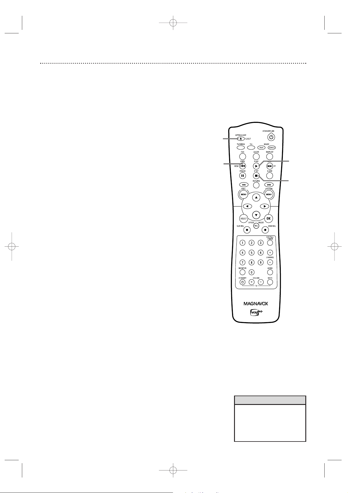
3
Press PLAY B.
4
Press STOP C to stop playback.
5
Press PREV/REW H to rewind the videotape.
6
After the videotape stops, press OPEN/CLOSE/EJECT A to
remove the videotape.
• You must connect the Recorder
to a TV using the RF coaxial
cable or composite video in
order to use the VCR features.
These hookups are explained on
pages 10 and 14.
Helpful Hint
1
2
Turn on the TV.
Insert a videotape in the
cassette compartment.
4
6
5
3
E9490UD_EN.qx3 04.8.3 11:55 AM Page 20
Page 21
Quick Disc Playback 21
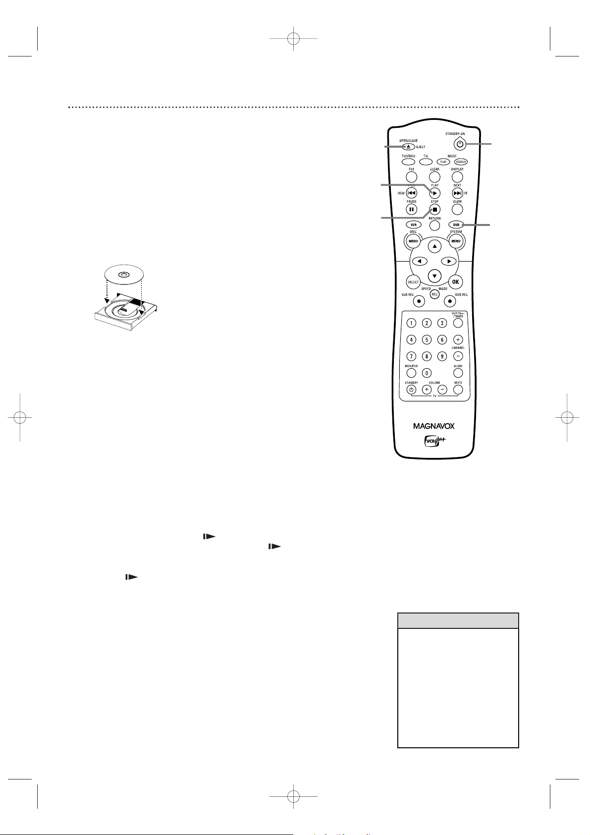
1
Press STANDBY-ONyyto turn on the Recorder.
Turn on your TV. Set it to the correct Video In channel. See
pages 9-16.
2
Press the DVD button on the remote control so the DVD
light appears on the front of the Recorder. You should see the
DVD background picture on the TV screen (if no Disc is in the
Recorder).
3
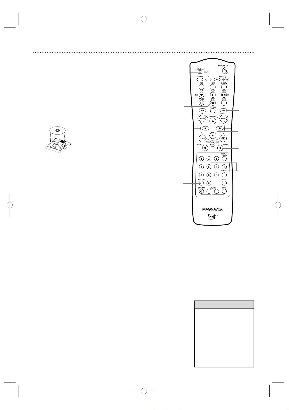
Press OPEN/CLOSE/EJECT A to open the disc tray.
Load your Disc in the tray, with the label facing up and the shiny
side facing down. If the Disc (DVD) is two-sided, make sure the label
of the side you want to play is facing up.
4
Press OPEN/CLOSE/EJECT A again to close the tray.
“Reading” will show on the display panel.The Recorder may read a
Disc for several seconds.
5
Press PLAY B to start playback.
• If you are playing a DVD, a Disc menu may appear. If the Title or
Chapter selections are numbered, press a Number button to select
an item. Or, press KK,LL,ss, or BBto select an item, then press OK.
Continue until you start playing the Disc. Or, follow the instructions in the DVD Disc menu.
• If you are playing a DVD+RW/DVD+R, the Index Picture Screen
will appear.
See page 34. Press K or L to select the Title you want
to play, then press OK. If the Disc is blank, the display will show
“EMPTY DISC.”
6
To stop play at any time, press STOP C.
If Auto resume is On, DVD play will resume at the same point the
next time you play the DVD.To play the DVD from its beginning,
restart play from the DVD’s Disc menu.
If Auto resume is Off, Resume will appear in the top left corner when you play the DVD later.While Resume appears,
press PLAY B to resume play from the point at which you last
stopped it. Otherwise, play will start at the beginning of the DVD.
Resume will disappear after about 15 seconds.
Auto resume is On when you purchase the Recorder. However, you
can turn it On or Off.
See page 56.
• If the Disc is Locked by Access
Control, you must enter the fourdigit code or unlock the Disc.
See pages 57-61.
•DVDs have a region code.Your
Recorder will not play Discs that
have a region code other than 1
(one)or ALL. See page seven.
• Auto resume does not affect
Audio CDs. If you restart play of
an Audio CD, play starts at the
beginning of the Audio CD.
Helpful Hints
P
O
W
E
R
O
N
/
O
F
F
LABEL
1
3-4
2
6
5
E9490UD_EN.qx3 04.8.3 11:55 AM Page 21
Page 22
22 Quick Disc Recording
The Recorder can record TV programming onto a DVD+RW or DVD+R.
Before you begin, set up TV channels.See pages 18-19 and 28. Use an unprotected, unfinalized, recordable DVD+RW/DVD+R.
1
Press DVD so the DVD light appears on the front of the Recorder.
2
Press OPEN/CLOSE/EJECT A to open the disc tray.
3
Insert a recordable DVD+RW/DVD+R with the label facing up.
Press OPEN/CLOSE/EJECT A to close the disc tray. The Index
Picture Screen will appear. See page 34. If the Disc is empty and has no
recordings,“EMPTY DISC” will appear on the display panel.
4
Press LLto select an empty Title box on a DVD+RW. To avoid
overwriting previous recordings on a DVD+RW, choose the last Empty
Title box.
On a DVD+R, the Recorder automatically starts recording at the end
of the Disc, so you do not need to select an Empty Title box.You cannot overwrite recordings on a DVD+R.
5
Press MONITOR to see TV channels through the Recorder.
6
Press CHANNEL +/- or the Number buttons to select the
channel you wish to record.
To r ecord material playing on equipment you connected to the
Recorder, select EXT1, EXT2 or CAM1. Choose the EXT (External) or
CAM (Camcorder) channel that matches the jack to which you connected the other equipment. See page 17.
If you are using a Cable Box/Satellite Receiver, set the Recorder to
channel 3 or 4 (or the EXT or CAM channel). (Choose the output
channel of your Cable Box/Satellite Receiver or the jacks to which you
connected the Cable Box/Satellite Receiver.) Then, change TV channels
at the Cable Box/Satellite Receiver. See page 11.
7
Press DVD REC I to record the selected channel. Recording will
begin after a few seconds. (The Disc has to prepare for recording.)
To pause recording, press PAUSE once on the remote.
To r esume recording, press DVD REC I again.
8
Press STOP Cto stop recording.The Index Picture Screen will reap-
pear after a few seconds. On a brief recording on a new DVD+RW, formatting the Disc will take a minute.
If you plan to play a DVD+R on another DVD Player, finalize the Disc. Follow
the steps on page 55.You cannot record or edit a DVD+R after you finalize it.
To edit your recordings, see page 54. However, editing changes may not be
accessible when you play the Disc on other DVD Players.
POW
ER ON/OFF
LABEL
•You cannot record only Audio
(sound) to a DVD+RW/DVD+R.
You must record both audio and
video (sound and picture).
•To erase a recording, see “Erase
this title” details on page 50.
•You cannot duplicate copyrighted DVDs, videotapes, or TV
broadcasts using the Recorder.
“COPY PROTECT” may appear
on the display panel if you
attempt this.
Helpful Hints
7
5
6
4
2-3
8
1
E9490UD_EN.qx3 04.8.3 11:55 AM Page 22
Page 23
Remote Control 23
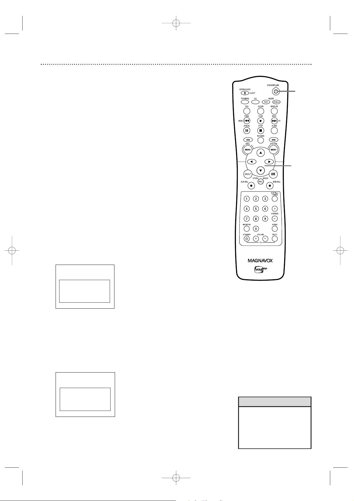
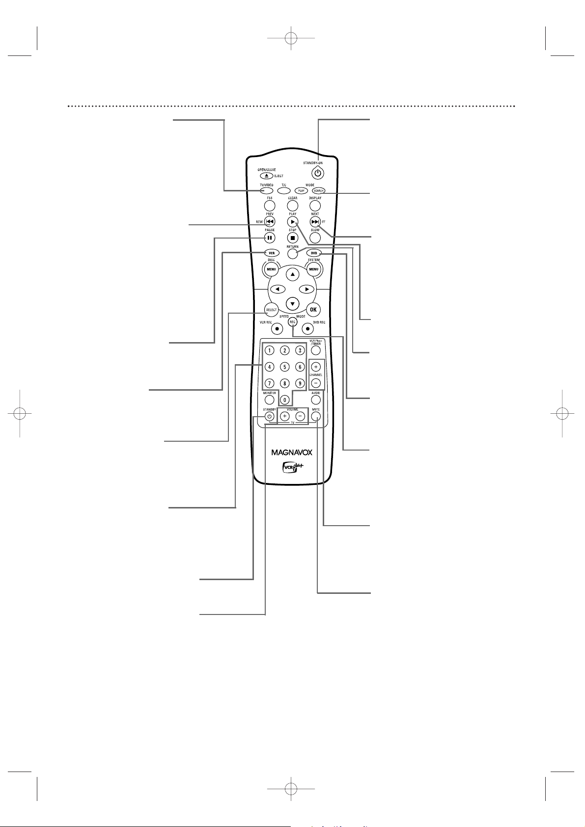
STANDBY-ON y Button
Press to turn on or off the power
of the Recorder.
Number Buttons
Use to select TV channels. If you
have Cable TV, channels 1-125 are
available. If you have an antenna,
channels 2-69 are available. In DVD
mode, press to select a Track or
Chapter for playback.
VCR Button
Press to activate the remote
control in VCR mode.
Press to select the VCR output mode.
SELECT Button
In DVD mode, press to adjust
timer recording settings.
See
page 45.
Press to choose Interlaced or
Progressive Scan. See page 63.
PREV/REW H Button
In DVD mode, press to return
to the beginning of the current Chapter/Track. Press
repeatedly to return to previous Chapters/Tracks. Press
and hold for two seconds to
search backward during play.
In VCR mode, press to search
a videotape.
See pages 75 and 76.
REC SPEED/MODE Button
Press to select a Disc or videotape recording speed.
See pages 52 and 69.
This determines the quality of
the recording and the length of
time you can record
.
TV VOLUME +/– Buttons
Press to adjust the volume of
some Magnavox TVs.
The TV VOLUME +/– buttons
do not work with all TVs.
TV MUTE Button
Press to mute the sound on
some Magnavox TVs.
The TV MUTE button does
not work with all TVs.
TV/VIDEO Button
Press to switch between TV
and Video positions. In Video
position, watch a Disc/videotape or watch/record TV programs (changing channels at the
Recorder).
Use TV position to watch TV
channels (changing channels at
the TV) or watch one program
while recording another.
CHANNEL +/- Buttons
Press to change TV channels
at the Recorder in Monitor or
VCR mode.
Press to adjust videotape
tracking during. See page 77.
DVD Button
Press to activate the remote
control in DVD mode.
Press to select the DVD output mode.
RETURN Button
Press to go to a previous
menu on a Video CD or some
DVDs.
NEXT/FF G Button
In DVD mode, press to skip
to the next Chapter or Track
during play. Press and hold for
two seconds to search forward during play.
In VCR mode, press to search
a videotape. See pages 75-76.
PLAY B Button
Press to begin Disc or videotape playback.
PAUSE k Button
Press to pause Disc or videotape play or recording (except
OTR).
SEARCH MODE Button
In VCR mode, press for a Time
Search or an Index Search. See
page 75.
TV STANDBY y Button
Press to turn on or off the power of
some Magnavox TVs.
E9490UD_EN.qx3 04.8.3 11:55 AM Page 23
Page 24
24 Remote Control (cont’d)
• When VCR REC I is pressed in DVD mode, the Recorder switches to
VCR mode and starts recording on the videotape.
• When DVD REC I is pressed in VCR mode, the Recorder switches to
DVD mode and starts recording on the DVD+R/DVD+RW.
Helpful Hints
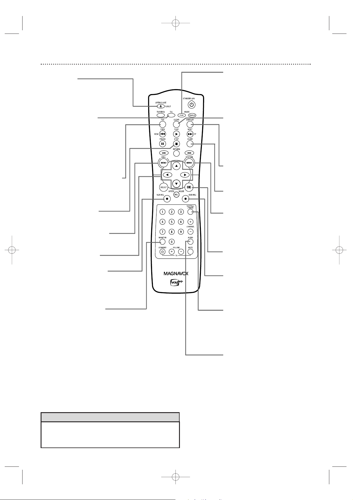
FSS Button
(Favorite Scene Selection)
Press to display or remove the
Favorite Scene Selection menu
during playback of a DVD+R
or DVD+RW. See page 54.
T/C Button
(Title/Chapter)
Press to select “T”
(Title/Track) or “C” (Chapter)
in the Menu Bar. Then press
op to select the
Title/Track/Chapter you want
to play.
This button has no effect
during Monitor mode.
VCR Plus+/TIMER button
Press to set a timer recording with
the VCR Plus+ programming system.
See page 46.
Press to access or remove the
Timer Recording menu in DVD
mode. See pages 45-47.
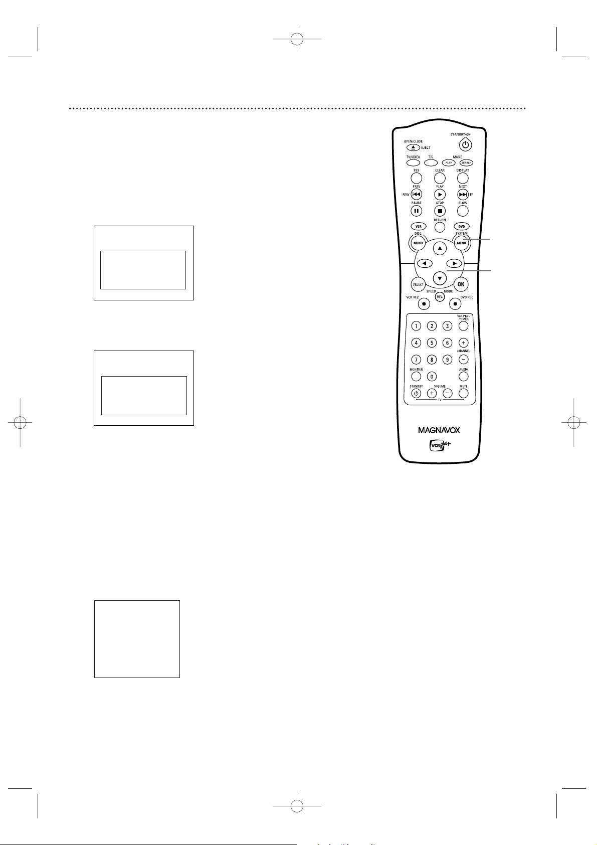
DISC MENU Button
Press to access or remove a DVD
Disc menu in DVD mode.
ops B Buttons
Press to select menu items.
STOP C Button
Press to stop playback or
recording.
VCR REC I Button
Press to begin VCR recording.
See page 69.
Press repeatedly to start a
One-Touch Recording on a
videotape.
See page 71.
PLAY MODE Button
Press during Disc play to
choose a Repeat, Shuffle, or
Scan mode.
OK Button
Press to acknowledge or
approve a menu selection.
DISPLAY Button
In VCR mode, press to see
status displays. See page 68.
OPEN/CLOSE/EJECT A
Button
Press to open or close the
Disc tray in DVD mode. Press
to eject a videotape in VCR
mode.
MONITOR Button
Press to choose Disc mode or
Monitor mode. In Disc mode,
use the Index Picture Screen
or view Disc playback. In
Monitor mode, watch TV
channels through the
Recorder or make a Disc
recording. See page 22.
CLEAR Button
In DVD mode, press to delete
the last entry of information
into a menu. Press to clear a
timer recording. See page 47.
In VCR mode, press to reset
the videotape counter.
See
page 74.
SYSTEM MENU Button
Press to access or remove the
Recorder’s Setup menu. This
also puts the Recorder in
DVD mode automatically.
DVD REC I Button
Press to start a Disc recording.
Press repeatedly to start a
One-Touch Recording on a
DVD+R or DVD+RW.
AUDIO Button
In DVD mode,
press to select a different audio language during DVD
play. Multiple languages must be
available on the DVD.
See page 37.
In VCR mode, press to select HIFI or
MONO. See page 76.
SLOW Button
Press to view a videotape in
slow motion. See page 76.
E9490UD_EN.qx3 04.8.3 11:55 AM Page 24
Page 25
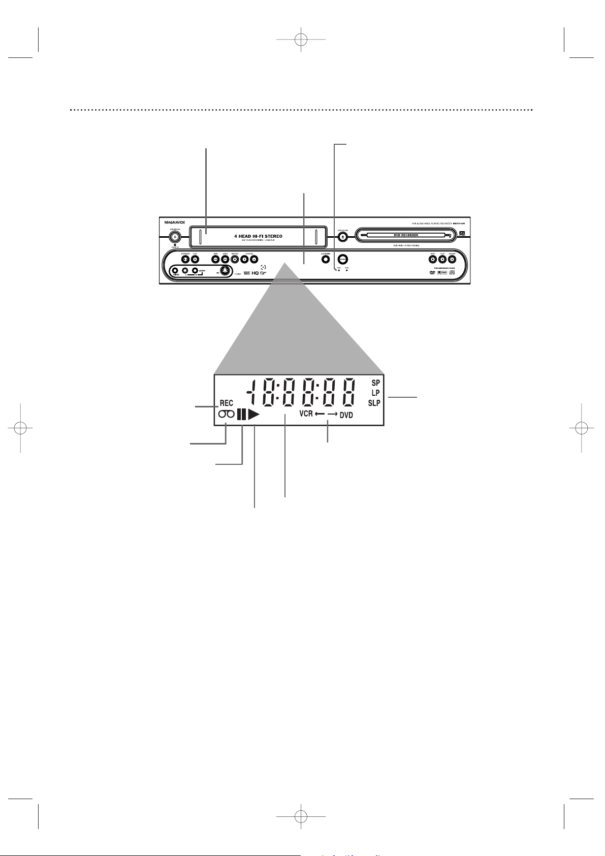
Cassette Compartment
Insert a video cassette here.
VCR light (Orange)
This light appears when the Recorder is in VCR
mode.You can only watch videotapes when the
VCR light is on.
Indicates a videotape
is in the Recorder
Appears if videotape
play is paused or
during slow motion
videotape play
Appears during
videotape play
Appears during recording;
flashes when recording is
paused
Indicates the elapsed playing time of a
videotape; also displays the remaining
time for an OTR
Indicates the
selected tape
speed
Appears during
DVD to VCR or
VCR to DVD
duplication
Display Panel (VCR) 25
VCR Display Panel
Messages about current VCR
operations appear here.
See Display Messages below.
E9490UD_EN.qx3 04.8.3 11:55 AM Page 25
Page 26
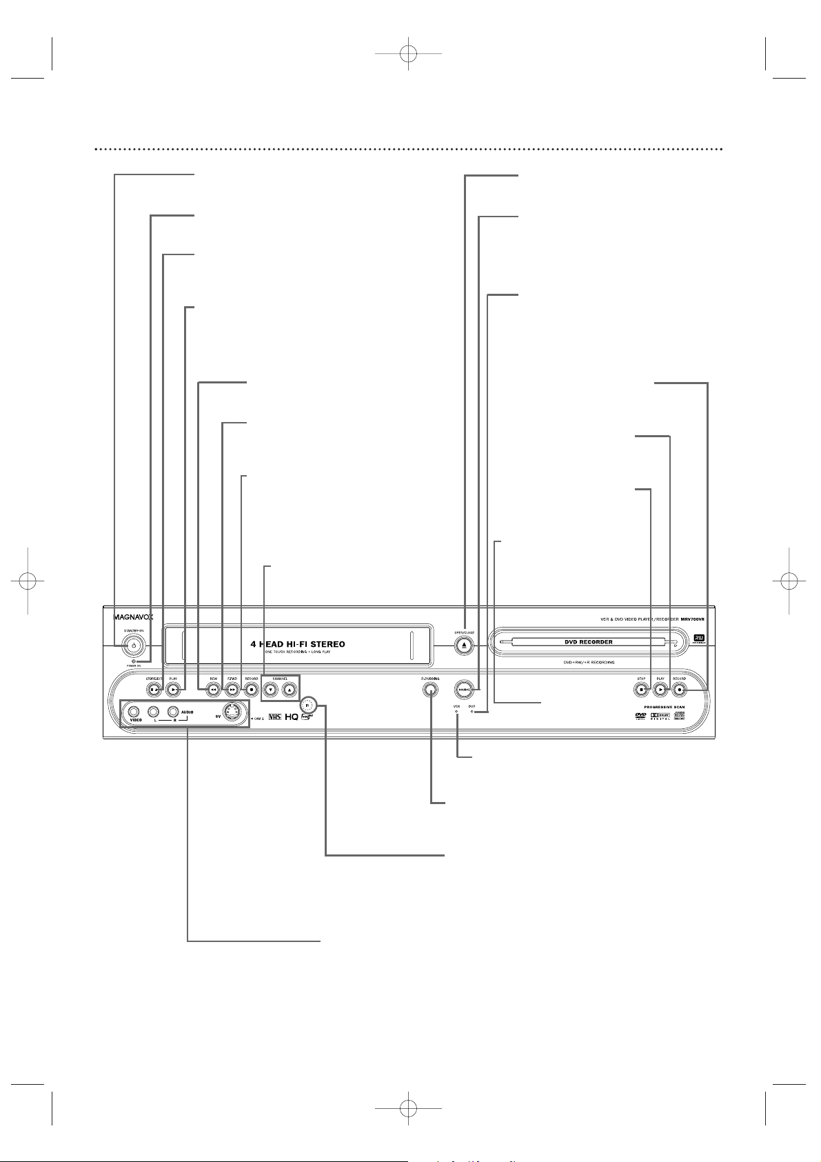
26 Front Panel
D.DUBBING Button
Press to start DVD to VCR or VCR to
DVD duplication. See pages 44 and 73.
IR (infrared) Remote Sensor
Receives a signal from your Recorder’s
remote control so you can work your
Recorder from a distance.
Point the remote here, not at your TV.
STANDBY-ON y Button
Press to turn the power on or off.
POWER ON Light
Appears when the power is on.
STOP C / EJECT A Button (VCR)
Press once to stop videotape playback.When
play is stopped, press to eject the videotape.
PLAY B Button (VCR)
Press to play a videotape.
Press to release Slow, Search, or Still mode and
return to playback. See page 76.
REW E Button (VCR)
Press to rewind a videotape. See page 76.
F.FWD D Button (VCR)
Press to fast forward a videotape.
See page 76.
RECORD I Button (VCR)
Press to start a videotape recording. See
page 69.
Press repeatedly to start a One-Touch
Recording.
See page 71.
CHANNEL KLButtons
Press to select TV channels.
SV (S-Video),VIDEO and AUDIO In jacks
Use these jacks when connecting a Camcorder or other equipment to the
Recorder. See page 17. When recording material that is playing on the other
equipment, set the Recorder to CAM1 in monitor mode.
DVD OPEN/CLOSE A Button
Press to open or close the Disc Tray.
SOURCE Button
Press to select DVD mode or VCR
mode.The DVD light appears in DVD
mode.The VCR light appears in VCR
mode.
DVD Light
This light appears when the Recorder is
in DVD mode.
RECORD I Button (DVD)
Press to start a Disc recording.
See page 22.
PLAY B Button (DVD)
Press to start Disc playback.
See page 21.
STOP C Button (DVD)
Press to stop Disc playback.
See page 21.
DVD Display Panel
Shows Disc status in DVD
mode.
VCR Light
This light appears when the Recorder is
in VCR mode.
E9490UD_EN.qx3 04.8.3 11:55 AM Page 26
Page 27
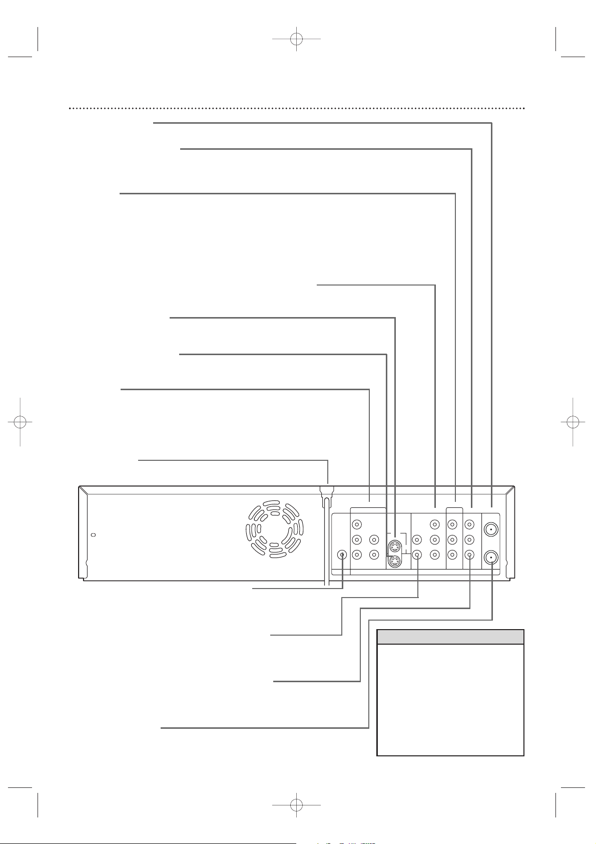
Rear Panel 27
DVDDVD/VCR
S-VIDEO
AUDIO
OUT
DIGITAL
AUDIO OUT
COAXIAL
COMPONENT
VIDEO OUT
Y
IN
OUT
P
B
PR
L
R
COMPONENT
VIDEO IN
Y
P
B
PR
AUDIO
IN
L
R
ANTENNA
IN
VIDEO OUTVIDEO IN
AUDIO OUTAUDIO IN
L
L
R
R
OUT
EXT1 EXT2
EXT2
ANTENNA IN jack
Connect your antenna or Cable TV signal here. See pages 10-16.
VIDEO OUT jack (yellow)
Connect the yellow video cable (supplied) here and to the TV’s
Video In jack.This supplies the picture for both VCR and DVD
modes. See page 14.
EXT2 Jacks
VIDEO IN jack (yellow)
Connect a video cable from an optional Camcorder,VCR, or DVD
Player here. See page 17.
AUDIO IN Jacks / Left (white) and Right (red)
Connect audio cables coming from the audio out jacks of a camcorder, another VCR, another DVD Player, or Stereo here. See
page 17. This will be useful if you want to copy a videotape or
watch material that is playing on other equipment.
COMPONENT VIDEO OUT (Y PB PR) jacks (red, green, blue)
Connect component video cables (not supplied) here and to the
Component Video In jacks of a TV. See page 12.
EXT2 S-VIDEO IN jack
Use an S-video cable (not supplied) to connect this jack to the
S-Video Out jack of optional additional equipment. See page 17.
EXT2 S-VIDEO OUT jack
Connect an S-Video cable here and to a TV’s S-Video In jack. See
page 13.
EXT1 jacks
AUDIO IN jacks / Left (white) and Right (red)
Connect audio cables here and to the AUDIO OUT jacks of other
equipment. See page 17.
COMPONENT VIDEO IN (Y PB PR) jacks (red, green, blue)
Connect these jacks to the Component Video Out jacks of optional video equipment (for example, a DVD Player). See page 17.
AC Power Cord
Connect to a standard AC outlet to supply power to the Recorder.
•
Use the same EXT (external) number
for each pair of audio and video connections. For example, if you use EXT 2
S-VIDEO IN, use the EXT 2 AUDIO IN
jacks.
•
Do not touch the inner pins of the
jacks. Electrostatic discharge may damage the unit permanently.
•
You only need one audio and one video
connection to a TV.You might not use all
the jacks.
Helpful Hints
DVD COAXIAL DIGITAL AUDIO OUT Jack
Connect a coaxial digital audio cable (not supplied) here and to the
Coaxial Digital Audio In jack of a Stereo.This supplies audio only for
DVD mode. See page 16.
AUDIO OUT Jacks / Left (white) and Right (red)
Connect audio cables here and to the Audio In jacks of a TV or Stereo.
These jacks supply audio for both DVD and VCR modes.
Use these for a second connection to another TV, etc.
AUDIO OUT Jacks / Left (white) and Right (red)
Connect the supplied audio cables here and to the Audio In jacks of a TV
or Stereo. See pages 12-15. These jacks provide audio for both DVD and
VCR modes.
(Antenna) OUT Jack
Use the supplied RF coaxial cable to connect this jack to the ANTENNA
IN jack on your TV, Cable Box, or Satellite Receiver. See pages 10-16.
E9490UD_EN.qx3 04.8.3 11:55 AM Page 27
Page 28

28 TV Channel Programming
Although the Recorder selects available TV channels during Initial Setup,
you may want to repeat the process later if more channels become available in your area.This will erase and replace all previously stored channels.
To update the available channels, follow these steps.
● Make sure the Recorder is in DVD mode. Press DVD so the DVD light
appears on the front of the Recorder.
1
Press SYSTEM MENU. Pressssto select in the top left
corner of the menu bar at the top of the TV screen.
2
Press LLrepeatedly to select at the bottom of the second
menu page, then press BBto enter the Installation menu.
3
Auto Ch. Programming will be selected. Press OK. “Searching for
TV channels” will appear, along with a progress scale.The number of
channels found will show on the screen as the searching progresses.
This will take a few minutes, depending on the number of channels
available.
4
When the channel search finishes,“Auto ch. search complete” will appear, along with the total number of channels found.
Press SYSTEM MENU. The Installation menu will reappear.
If you are satisfied with the channels found, press SYSTEM
MENU repeatedly to remove the menu.You are finished.
To add or delete additional channels, pressLLto select
Add/Delete Channels, then go to step 5.
5
Press BB. A channel list will appear. Beside each channel number,
you will see “Delete” or “Add.”
6
Press KKor LLto select the channel you want to add or
delete, then press ssor B to choose Add or Delete for that
channel. Press OK to store your choice. “Stored” will appear
briefly in the lower left corner of the menu.
Repeat step 6 as often as necessary to add or delete all the channels
you want.
7
Press SYSTEM MENU repeatedly to remove all the menus
when you are finished.
• Access added channels by
pressing CHANNEL +/-.
Deleted channels will be
skipped. Delete channels you
rarely watch.You still can select
deleted channels with the
Number buttons.
• If new channels become available, or if you receive a channel the Recorder did not set,
add the channel.
• The Recorder detects whether
you connected an Antenna or
Cable TV signal. If you are not
receiving the correct channels,
reset your channels. Follow
steps 1-2 above. Press Lto
choose Cable/Antenna, then
press B.Press B or s to
choose Cable, Anten. (antenna),
or Auto (for the Recorder to
detect automatically). Press OK.
“Stored” will appear briefly in
the lower left corner of the
menu. Press SYSTEM MENU.
Press OK again to reset the
channels. When the search
ends, press SYSTEM MENU
repeatedly to clear the screen.
Helpful Hints
1,4,7
1-6
E9490UD_EN.qx3 04.8.3 11:55 AM Page 28
Installation
K
u B Auto Ch. Programming B
L
Add/Delete Channels
VCR Plus+ ch.
Time/Date
Cable/Antenna
To exit press
SYSTEM MENU
Installation
K Auto Ch. Programming
u B Add/Delete Channels B
L
VCR Plus+ ch.
Time/Date
Cable/Antenna
To exit press
SYSTEM MENU
Page 29

VCR Plus+®Channels 29
If you intend to use the VCR Plus+®programming system, program the
Recorder with your local channel information.This will only take a few minutes. Since the channel numbers of the stations you receive may not be the
same as the station numbers, and since channel numbers differ from area to
area, you must set up channels in order for the system to work efficiently.
Before you begin, make sure you have 1) a cable TV channel list, if applicable
(you can request one from your cable TV company), and 2) a chart that lists
VCR Plus+ channel numbers, which you can find in your TV guide or the TV
listings of your local newspaper.
● Make sure the Recorder is in DVD mode. Press DVD so the DVD light
appears on the front of the Recorder.
1
Press SYSTEM MENU. Pressssto select in the top left
corner of the menu bar at the top of the TV screen.
2
Press L repeatedly to select at the bottom of the sec-
ond menu screen, then press B to enter the Installation menu.
3
Press KKor LLto select VCR Plus+ Ch. (channel), then press BB.
4
PressKKor LLto select a VCR Plus+ Ch. number, then press
s or B to enter the corresponding Channel number from
your TV guide list.
Refer to the list from your local newspaper or TV guide for the VCR
Plus+ channels and corresponding TV channel numbers for your
area.These are the numbers you will enter as the Channel number
as you complete the chart on the screen.
5
Press OK to store the Channel number. “Stored” will appear
briefly in the lower left corner of the menu. Repeat steps 4-5 as
often as necessary to complete the chart.
6
When you are finished, press SYSTEM MENU repeatedly to
remove all the menus.
•
Only memorized channels will
be available at step 4.To add
more channels, see page 28.
Helpful Hint
Call letters
(Local TV station)
Guide Channel
(Guide channel number)
TV Channel
(Local channel number)
Channel Line-Up Chart
1,6
1-5
E9490UD_EN.qx3 04.8.3 11:55 AM Page 29
Installation
Auto Ch. Programming
K Add/Delete Channels
u B VCR Plus+ ch. B
L
Time/Date
Cable/Antenna
To exit press
SYSTEM MENU
Installation
VCR Plus+ ch.
VCR Plus+ ch. Channel
KK...
u 001 s 018 B
L
002 -- -- -003 -- -- -004 -- -- -005 -- -- --
L
... To store
Press OK
Page 30

30 Clock Setting
Time/Date Automatic
The Recorder can set the time and date automatically by referring to a PBS
station. If the Recorder chooses an incorrect PBS channel or sets the
time/date incorrectly, set the clock manually. See page 31.
Before you begin, make sure TV channels are set. See page 28.
● Make sure the Recorder is in DVD mode. Press DVD so the DVD light
appears on the front of the Recorder.
1
Press SYSTEM MENU. Press s to select in the top left
corner of the menu bar at the top of the TV screen.
2
Press L repeatedly to select at the end of the second
menu screen, then press B to enter the Installation menu.
3
Press L repeatedly to select Time/Date, then press B.
4
Automatic will be selected. Press B.
5
With PBS Channel selected, press s or B to choose the
channel number of your PBS station, then press OK.
If you do not know your PBS channel number, choose Auto. The
Recorder will choose a PBS station for you and set the time.
If you want to set the clock manually, choose Off.The Recorder will
not update the time automatically according to a PBS station.
6
Press LLto choose Daylight Saving.Press s or B to choose
On, Off, or Auto, then press OK. Choose Auto if you want the
clock set according to the PBS station’s Daylight Savings Time schedule.
7
Press L to choose Time Zone. Press s or B repeatedly to
choose your time zone, then press OK.
If you want the Recorder to use the time zone from which your PBS
station broadcasts, choose Auto. But,if your PBS station broadcasts
from a different time zone than the one in which you live, be sure to
select your time zone instead.
8
Press SYSTEM MENU repeatedly to remove the menus. Press
STANDBY-ON yyto turn off the Recorder. In a few minutes, the
time will appear on the display panel on the front of the Recorder.
If the Recorder cannot find the time, you may see an error message
when you turn on the Recorder. Check the PBS channel and try again.
Or, set the clock manually. See page 31.
• The Recorder may set the clock
when you complete Initial
Setup. If the correct time
appears on the display, you do
not need to reset the clock.
• The factory default setting of
Daylight Saving is On.
• The Recorder can use the PBS
channel to set the clock only if
the PBS channel is a memorized channel.To set up channels, see page 28.
Helpful Hints
8
1,8
1-7
E9490UD_EN.qx3 04.8.3 11:55 AM Page 30
Time/date
Automatic
K
u PBS Channel s 010 B
L
Daylight Saving Off
Time Zone Auto.
To store
Press OK
Time/date
Automatic
K PBS Channel 010
u Daylight Saving s Off B
L
Time Zone Auto.
To store
Press OK
Time/date
Automatic
PBS Channel 010
K Daylight Saving Off
u Time Zone s Auto. B
L
To store
Press OK
Page 31

Clock Setting (cont’d) 31
Time/Date Manual
If the Recorder does not set the time and date correctly using the
Time/Date Automatic feature, set the clock manually by following the steps
below.Manual clock setting overrides Automatic clock setting.
● Make sure the Recorder is in DVD mode. Press DVD so the DVD light
appears on the front of the Recorder.
1
Press SYSTEM MENU. Press s to select in the top left
corner of the menu bar at the top of the TV screen.
2
Press L repeatedly to select at the end of the sec-
ond menu, then press B to enter the Installation menu.
3
Press L repeatedly to select Time/Date, then press B.
4
Press L to choose Manual, then press B.
5
Time will be highlighted. Press s or B to choose the correct
time in hours and minutes, then press OK.Or, press the
Number buttons to quickly enter the time in hours and minutes,
then press OK.
6
Press L to choose AM/PM, then press s or B to choose
AM or PM. Press OK.
7
Press L to choose Year, then press s or B to choose the
current year. Press OK.
8
Press L to choose Month, then press s or B to choose
the current month. Press OK.
9
Press L to choose Date, then press s or B to choose the
current date. Press OK.
10
Press L to choose Daylight Saving, then press s or B to
choose On or Off. Press OK.
11
Press SYSTEM MENU repeatedly to remove all menus.
•
In order for the clock to remain
set as you specified manually,
you may need to set Daylight
Saving to Off.
• If you set up channels again as
described on page 28, you may
need to reset your clock.
• If you change any item manual-
ly (Time, AM/PM,Year, Month,
Date, Daylight Saving), PBS
Channel will change to Off
automatically. See page 30.
Helpful Hints
1-10
1,11
E9490UD_EN.qx3 04.8.3 11:55 AM Page 31
Time/date
Manual
K
u Time s 04:01 B
L
AM/PM PM
Year 2004
Month 06
Date 19
Daylight Saving On
To exit press
SYSTEM MENU
Page 32

32 Menu Bars
You can use the Menu Bars to access or operate some DVD or Recorder features.You cannot access the Menu Bars during recording.
When a Menu Bar is on the screen, press K,L, s, and B on the remote to
select or change an item.
Menu Bar 1
*Press SYSTEM MENU once to access Menu Bar 1.The following
items are in Menu Bar 1.
Depending on the available Disc features,you may
not be able to access each item at all times. Only available features can be
selected.
User Preference Settings Set your preferences for Disc audio and
video quality, depending on the equipment you connected to the
Recorder. Also set up Languages, Access Control, Record Settings,
Remote Control settings, Installation features, and other Recorder features as detailed throughout this manual.
Title/Track Select to choose an available Disc Title or Track for playback. Use the Number buttons or K or L to select the Title you want.
Play will start automatically.
Chapter Select to choose an available Disc Chapter for playback. Use
the Number buttons or
K or L to select the Chapter you want. Play will
start automatically.
Audio Language If the current DVD has multiple audio soundtracks,
choose one here. For example, some DVDs let you play the movie in
other languages or hear a director’s commentary during playback. Check
the Disc case for details. See page 37.
Subtitle Language If the current Disc has subtitles,select a language
here. See page 37.
Angle Select to choose a different camera angle, if available, during
DVD play. See page 38.
Zoom Select to enlarge the DVD picture by 2, 3, or 4 times the normal
size during playback. See page 38.
Menu Bar 2
*While in Menu Bar 1, press B repeatedly to move to Menu Bar 2.
The following items may be available in Menu Bar 2.
Sound Mode Select to choose a sound mode: Stereo (st) or Dolby
Surround compatible (sur). See page 39.
Frame-by-frame playback Select for forward or reverse frame-byframe playback. Press L, then press s or B to move the DVD or Video
CD picture backward or forward one frame at a time. See page 39.
Slow motion Select to slow the speed of DVD, DVD+R, or DVD+RW
playback. See page 40.
Fast motion Select to play a DVD, DVD+R, or DVD+RW forward or
backward at four, eight,or 32 times the normal play speed. Press L, then
press s or B to choose a backward (-) or forward speed.
Time Search Select to enter a specific time within the current Title or
Track at which you want play to begin. See page 41.
W
Z
Y
d
H
E
a
X
E9490UD_EN.qx3 04.8.3 11:55 AM Page 32
Page 33

Disc status icons
recording
stop
pause play
pause recording
fast forward
fast reverse
slow motion
Disc type icons
DVD+R
DVD+RW
DVD-Video
Super Video-CD
Video-CD
no Disc
Disc error
H
1/4
J
x4
K
x4
0 ;
pause
;
pause
9
stop
0
rec
Status Box
The Status Box shows the current status of the Recorder and information about the current Disc,
including Disc type and playing time. Set Status box to On if you want to see the following icons briefly
when you access a feature. See page 62.
On-screen Symbols, Status Box 33
Repeat Chapter The current Chapter
will play repeatedly.
See page 42.
Repeat Title The current Title will play
repeatedly. See page 42.
Repeat All The entire Disc will play
repeatedly. See page 42.
Repeat A Point A for Repeat A-B playback has been entered.
See page 42.
Repeat A-B A segment of the Disc will
play repeatedly. See page 42.
OFF Each repeat option will appear in
turn every time you press PLAY MODE.
OFF will appear at the last.
Shuffle The Tracks or Chapters will play
in random order. To start shuffled play,
press PLAY MODE repeatedly until
“shuffle” appears on the TV screen.
Scan The first 10 seconds of each
Chapter/Track will play.
See page 41.
Angle Multiple angles are available.
See page 38.
Locked The current Disc is Locked and
cannot play. See pages 57-61.
Safe The current Disc is authorized for
playback.
See pages 57-61.
“X” The feature you just attempted is
not available on the current Disc or at the
current time.
On-screen Symbols
The following symbols will appear briefly on the TV screen when you activate some Disc features.
scan
2/2
locked
safe
shuffle
repeat
title
chapter
A -
A - B
OFF
DVD+R
DVD
SVCD
RW
VCD
no disc
error
E9490UD_EN.qx3 04.8.3 11:55 AM Page 33
Page 34

Title description
Includes program name (or channel/source and
time at which it was recorded), length of
recording, the speed in which it was recorded,
and the date of recording (if clock was set).
Cue
Go to the Disc Information Screen or to a
Title on a previous screen. Disc Information
Screen details are on page 53.
34 Index Picture Screen
The Index Picture Screen shows your recordings on a DVD+RW or DVD+R. It
appears automatically when you insert a DVD+R or DVD+RW or when you stop
playback or recording.The Disc must contain recordings.
An Index Picture represents each recording. Next to the Index Picture is the program
name, length of recording, recording mode/speed, and date of recording. If the recording has no name, the recording source and time will appear instead (for example, the
recorded TV channel and the time at which you started recording the channel).
Empty disc areas (erased Titles or blank space at the end of the Disc) also appear in
the Index Picture Screen.“Empty title” and the amount of remaining recording time
appear beside the empty Index Picture box.
The Index Picture Screen will dim after several minutes of no use.To brighten the
Index Picture Screen again, use the Recorder or its remote control.
Titles
The Index Picture Screen shows three Titles per screen. Press K or L to move to
other recordings.
Press STOP C to move directly to the first recording on the Disc.
Disc Bar
The Disc Bar appears at the right of the Index Picture Screen.This overviews all
recordings on the Disc, as well as any empty spaces.
On the Disc Bar, the Disc Pointer indicates your current position on the Disc. You
can press and hold the NEXT/FF G button to scroll through the Disc Bar. Moving
through the recordings by pressing K or L also moves the Disc Pointer. On a
DVD+RW, resume play or recording from this point by pressing OK for playback or
DVD REC I for recording. Later recordings will be overwritten. On a DVD+R,
resume play from the Disc Pointer location by pressing OK. However, on a DVD+R,
recording begins at the last empty title space when you press DVD REC I.
Title Settings Menu
When you select an Index Picture, press B to go to its Title Settings Menu.You can
name, play, or erase the Title. See page 50.
Disc Pointer
Shows the current Title
number and its position
within the Disc.
Disc Bar
Timer Information Box
Displays the current time or
the time/date of the next
scheduled timer recording.
See page 35.
Tuner Information Box
Displays the current TV
channel or video source (if
additional equipment is connected to the Recorder).
See page 35.
Current Title
Index Picture
An image representing a
recording.An empty box represents an area on the Disc
that is empty and available for
recording. To personalize the
Index Picture, see page 54.
E9490UD_EN.qx3 04.8.3 11:55 AM Page 34
Page 35

Information Boxes 35
Warning box
Appears near the bottom of the TV screen when appropriate. Examples and details are on page 48.
Tuner Information box
Appears briefly on the left side of the TV screen in Monitor mode and identifies the current TV channel
or Video source. For example, if EXT1 appears in the Tuner Information Box, you can view or record
the material playing on the equipment connected to the EXT1 IN jacks on the rear of the Recorder.
To r eceive TV stations,make sure you have connected an Antenna or Cable TV signal to the ANTENNA IN jack on the Recorder. See pages 10-16. Press MONITOR to go into Monitor mode and view TV
channels.
Current TV channel No signal - Channel is not Copy-protected signal
receivable or no equipment
is connected to the designated jack.
Timer Information box
Displays the start time or date of the next scheduled timer recording and appears in the Index Picture
Screen.You cannot remove it.
It appears briefly at the beginning of a timed One-Touch Recording. It does not appear during recording
or Disc playback.
Timer recording due later today Timer recording set for another day
within the upcoming year
The time at which the current Current time; no timer recordings
One-Touch Recording will end. are scheduled.
Disc locked
012
012
10:15
pm
4
E9490UD_EN.qx3 04.8.3 11:55 AM Page 35
Page 36

36 Title/Disc Menus, Chapter/Track Selection
Title/Disc Menus
● Before you begin, make sure the Recorder is in DVD mode. Press DVD so
the DVD light appears on the front of the Recorder.
1
Press DISC MENU during Disc play.
For a DVD, if the current Title has a menu, the Title menu will
appear on the screen. Otherwise, the Disc menu will appear. The
menu will list features available on the current DVD and will vary for
every DVD.
For a DVD+RW or DVD+R, the Index Picture Screen will appear.
See page 34.
2
Press Kor L to select items in the menu or Index Picture
Screen, then press OK. Repeat this process until you set up all
the features you want or until play begins.
Chapter/Track Selection
● Before you begin, make sure the Recorder is in DVD mode. Press DVD so
the DVD light appears on the front of the Recorder.
1
Press NEXT/FF G during play to go to the next
Track/Chapter. Press PREV/REW
j once to return to the
beginning of the current Track/Chapter.
Press PREV/REW j
repeatedly to step back to previous Tracks/Chapters.
2
Or, to go directly to any Track/Chapter during play, press
the Number buttons to enter the Track/Chapter number.
If you enter an invalid number, the current Track/Chapter may continue to play. Or, an incorrect Track/Chapter may begin to play. Make
sure the Track/Chapter number you enter is available on the Disc.
Make sure the Chapter is available within the current Title.The
Menu Bar will disappear automatically in a few seconds, or you can
press SYSTEM MENU to remove it quickly.
1
2
1
2
E9490UD_EN.qx3 04.8.3 11:55 AM Page 36
Page 37

Audio Language, Subtitles 37
Audio Language
Some DVDs are recorded in different languages. For example, you may be
able to watch the same movie in French, Spanish, etc.The movie may have
special audio features, such as a director’s commentary or music soundtrack. If these are available on the DVD, access the different languages or
featured soundtracks by following these steps.
● Before you begin, make sure the Recorder is in DVD mode. Press DVD so
the DVD light appears on the front of the Recorder.
1
During DVD play, press the AUDIO button.
Y Audio will be selected in the Menu Bar.
2
Within five seconds, press the AUDIO button repeatedly to
see the different languages available. Or, press K or L repeat-
edly to see the different languages.The language you select will be
audible in a few seconds; the Menu Bar will disappear.
The languages or options may be abbreviated.For example, French
may be “Fr.” See your Disc case for details on available audio features and explanations.
W X Y Z a
121en 1en
K
L
no off
~
LF
DVD play
0:29:40
0:00:07
sB
W X Y Z a
121en
K
L
1nooff
~
LF
DVD play
0:29:40
0:00:07
sB
Subtitles
Some DVDs include subtitles in different languages. Or, material you
recorded onto a DVD+RW or DVD+R might include subtitles.To choose
subtitles, follow these steps.
● Before you begin, make sure the Recorder is in DVD mode. Press DVD so
the DVD light appears on the front of the Recorder.
1
During play, press SYSTEM MENU so Menu Bar 1 appears
at the top of the TV screen.
2
Press B repeatedly to select ZZ(Subtitle) in the Menu Bar.
3
Press K or L to see the available subtitle languages. Subtitles will
appear after a few seconds.
You can choose subtitles only if they are available on the Disc.The
languages may be numbered or abbreviated, such as “En” for English.
4
Press SYSTEM MENU to remove the Menu Bar.
1-2
1,4
2-3
E9490UD_EN.qx3 04.8.3 11:55 AM Page 37
Page 38

38 Zoom, Camera Angle
Zoom
Zooming lets you enlarge the video image during play and pan through the
enlarged image.
● Before you begin, make sure the Recorder is in DVD mode. Press DVD so
the DVD light appears on the front of the Recorder.
1
During play, press SYSTEM MENU so Menu Bar 1 appears
at the top of the TV screen.
2
Press B repeatedly to select a (Zoom) in the Menu Bar.
3
Press K or L to choose 2, 3, or 4. Play will pause.The still pic-
ture will appear at 2, 3, or 4 times the normal size.
4
To move the enlarged picture (pan), press OK. Then, press
K, L, s, or B to move the picture.
5
Press OK again to see the still, zoomed picture without the
Menu Bar.
6
To r eturn to regular play, press PLAY B.
7
Press SYSTEM MENU to remove the Menu Bar again.
Camera Angle
Some DVDs include scenes recorded from different angles or perspectives.
To watch segments from a different angle, follow these steps.
● Before you begin, make sure the Recorder is in DVD mode. Press DVD so
the DVD light appears on the front of the Recorder.
1
During DVD play, press SYSTEM MENU so Menu Bar 1
appears at the top of the TV screen.
2
Press B repeatedly to select (Angle) in the Menu Bar.
3
Press K or L to select a different angle. In a few seconds, play
changes to the selected angle.
If the Angle symbol appears in the top left corner of the TV screen
during play, multiple angles are available. Simply press K or L to
switch among the different angles.
W X Y Z a
121en 1 no 2
K
L
~
LB
DVD pause
0:29:40
0:00:07
sB
Press OK to pan
1,7
2-5
6
1
2-3
E9490UD_EN.qx3 04.8.3 11:55 AM Page 38
2/2
~
LF
DVD play
0:29:40
0:00:07
W X Y Z a
121en 1 1/2
sB
K
L
off
o
p
2/2
Page 39

Still Picture/Frame-by-Frame Play, Sound 39
Still Picture/Frame-by-frame Play
To quickly pause play, press PAUSE k on the remote. To advance the still
picture one frame at a time, press PAUSE k repeatedly.To resume play,
press PLAY B.
To freeze the picture using the Menu Bar, follow these steps.
● Before you begin, make sure the Recorder is in DVD mode. Press DVD so
the DVD light appears on the front of the Recorder.
1
Press SYSTEM MENU during play so Menu Bar 1 appears.
2
Press B repeatedly to select in Menu Bar 2.
3
Press L to freeze the picture. Press s or B to move the
picture backward or forward one frame at a time.
Do not leave a still picture on your TV more than five minutes. This
may etch the image onto your picture tube permanently. Other still
visual elements, such as TV station logos or video games, also will
damage your TV if left too long.
4
Press PLAY B to resume regular play.
5
Press SYSTEM MENU to remove the Menu Bar.
Sound
Choose a sound setting based on the capabilities of the equipment to
which you connected the Recorder. See pages 10-16 and 65.
● Before you begin, make sure the Recorder is in DVD mode. Press DVD so
the DVD light appears on the front of the Recorder.
1
During play, press SYSTEM MENU so Menu Bar 1 appears
at the top of the TV screen.
2
Press B repeatedly to select d in Menu Bar 2.
3
Press K or L to select st (stereo) or sur (Dolby Surround).
Select st (stereo) to hear stereo sound.This will work with equipment that has right and left audio jacks (usually red and white).
Select sur (Dolby Surround) if your audio equipment is compatible
with Dolby Surround. If it is, usually a Dolby Pro Logic logo will
appear on the equipment.
4
Press SYSTEM MENU to remove the Menu Bar.
• The Recorder also refers to
Sound settings as Analog output.
The sound the Recorder sends to
your Stereo or TV is analog, or
two-channel, left and right. You
are using analog sound if you
used the red/white, left/right,
Audio jacks. See page 65.
Whether you adjust the sound
here or as described on page 65,
the results will be the same.
Helpful Hint
d H E
LF
DVD play
1 :2 3 : 4 5
0 :3 0 :02
sB
st
K
L
d H E
LB
DVD pause
0:29:40
0:00:07
st
e
o
2-3
1,5
4
1,4
2-3
E9490UD_EN.qx3 04.8.3 11:55 AM Page 39
Page 40

Searching
● Before you begin, make sure the Recorder is in DVD mode. Press DVD so
the DVD light appears on the front of the Recorder.
1
To search a Disc at four times the normal speed, press and
hold NEXT/FF i or PREV/REW j during play. Repeat
this to search at eight or 32 times the normal speed.The sound will
be mute.
On an Audio CD, press and hold NEXT/FF i or
PREV/REW j during play to search the Disc at four
times the normal speed. Sound will be intermittent. Repeat this
to search at eight times the normal speed. The sound will be mute.
Each press of NEXT/FF i or PREV/REW j switches between
the slower and faster search speed.
2
Press PLAY B to resume normal play.
40 Slow Motion, Searching
Slow Motion
To use the Menu Bar for slow motion, follow these steps.
● Before you begin, make sure the Recorder is in DVD mode. Press DVD so
the DVD light appears on the front of the Recorder.
1
During Disc play, press SYSTEM MENU so Menu Bar 1
appears at the top of the TV screen.
2
Press B repeatedly to select H (Slow motion) in Menu Bar
2, then press L. Play will pause.
3
Press s or B to select the required speed: -1, -1/2, -1/4 or -
1/8 (backward), or 1/8, 1/4, 1/2 or 1 (forward). The Disc will
start to play at the speed you selected, for example, one-half as fast
as normal (1/2).
Select 1 or press PLAY B to play the Disc at normal speed again.
Select 0 or press PAUSE k on the remote control to pause the picture.
4
Press SYSTEM MENU to remove the Menu Bar.
d H E
L F
DVD pause
0:00:22
0:00:05
st
-1 -1/2 -1/4 -1/8
s
0
B
1/8 1/4 1/2 1
K
1,4
2-3
1
2
E9490UD_EN.qx3 04.8.3 11:55 AM Page 40
Page 41

Time Search, Scan 41
Time Search
Time Search lets you choose a specific elapsed playing time at which you
want to begin playback.
● Before you begin, make sure the Recorder is in DVD mode. Press DVD so
the DVD light appears on the front of the Recorder.
1
Press SYSTEM MENU during Disc play so Menu Bar 1
appears at the top of the TV screen.
2
Press B repeatedly to select in Menu Bar 2.
3
Press L. Play will pause.A time edit box will appear, showing the
elapsed playing time of the current Chapter or Disc.
4
Press the Number buttons to enter the time at which you
want play to begin. Enter the hour, minutes, and seconds from left
to right in the box.
The time must be within the possible time of the current Chapter or
Disc. If it is not, play will not begin after you press OK at step 5.
Instead, a space in the time edit box will blink. Or,play may begin at the
wrong time. Refer to the Status box to see the time available, then
enter a correct time.
5
Press OK. After a few seconds, play will resume at the point you
selected.
6
Press SYSTEM MENU to remove the Menu Bar.
Scan
Scanning plays the first 10 seconds of each Chapter/Track on the Disc.
● Before you begin, make sure the Recorder is in DVD mode. Press DVD so
the DVD light appears on the front of the Recorder.
1
Press PLAY MODE repeatedly during play until “scan”
appears on the TV screen.
Starting with the current
Chapter/Track, the first 10 seconds of each Chapter/Track will play.
This will continue until the end of the Disc is reached or you
resume regular playback.
2
To stop scanning and continue regular play, press PLAY B.
d H E
L F
DVD pause
1:41:05
0:02:32
st
s
0:02:32
B
K
time edit box
elapsed playing time
Status box
total time
4
1,6
2,3,5
2
1
E9490UD_EN.qx3 04.8.3 11:55 AM Page 41
Page 42

42 Repeat, Repeat A-B
Repeat
You may play a Chapter,Track,Title or entire Disc repeatedly. All Discs do
not allow all the repeat options.You cannot play a DVD+R or DVD+RW
repeatedly. Check your Disc for details.
● Before you begin, make sure the Recorder is in DVD mode. Press DVD so
the DVD light appears on the front of the Recorder.
1
During Disc play, press PLAY MODE repeatedly to choose a
Repeat option.
Depending on the type of Disc, you may choose to
play the Chapter,Track, Title, or Disc repeatedly.
During DVD or Video CD play,the repeat symbols will appear
briefly on the TV screen.
See page 33.
2
To cancel repeat play, repeatedly press PLAY MODE to
choose “off ” or until all the repeat symbols or messages disappear
from the screen.
Repeat A-B
You also may set the Recorder to play only a specific portion of a Title,
Chapter, or Track repeatedly. Follow these steps.
● Before you begin, make sure the Recorder is in DVD mode. Press DVD so
the DVD light appears on the front of the Recorder.
1
Press PLAY B to start Disc play.
2
When the Disc reaches the point at which you want repeated play to begin, press PLAY MODE until the “repeat-A”
symbol appears on the TV screen.
3
When the Disc reaches the point at which you want to end
the segment, press OK.
The “Repeat A-B” symbol will appear on
the TV screen briefly.The segment will begin playing repeatedly.
4
To cancel Repeat A-B play, press STOP C.
1-2
1
2
4
3
E9490UD_EN.qx3 04.8.3 11:55 AM Page 42
Page 43

One-Touch Recording 43
● Before you begin, make sure the Recorder is in DVD mode. Press DVD so
the DVD light appears on the front of the Recorder.
1
Insert a recordable DVD+RW or DVD+R into the Recorder.
2
In the Index Picture Screen of a DVD+RW, press K or L to
select an Empty Title (or empty Index Picture box) on the Disc
that has enough time for the recording. Or, select the place at which
you want to start the new recording in order to overwrite other
recordings.
You may skip this step if you use Safe Record. See step 5.
Or, if you are using a DVD+R, you may skip this step. Recordings on
a DVD+R are made at the end of the Disc automatically. Previous
recordings are not overwritten.
3
Press MONITOR to see TV channels through the Recorder. Make
sure you have programmed channels. See page 28.
4
Press CHANNEL +/- or the Number buttons to select the
channel you wish to record.
If you are using a Cable Box/Satellite Receiver, enter channel 3 or 4
(the output channel of your Cable Box/Satellite Receiver) or the EXT
channel (that corresponds to the jacks to which you connected the
Cable Box/Satellite Receiver). Set the channel you want to record at
the Cable Box/Satellite Receiver. Leave it on for the recording.
5
Press DVD REC I twice to start a 30-minute recording.
Press DVD REC I repeatedly to record longer timed
recordings. The length of recording available depends on the cur-
rent recording mode/speed and the amount of time available on the
Disc. Recording mode/speed details are on page 52. Recording will
begin about 30 seconds after you press DVD REC I. (The Disc
takes this time to prepare for recording.)
Or, use Safe Record to have the Recorder automatically find the
empty space at the end of a DVD+RW; this prevents overwriting
other recordings.To do so, press and hold DVD REC I for about
two seconds, or until SAFE REC appears on the Recorder’s display
panel.Then, press DVD REC I repeatedly to choose the time length
you want for your recording.
If you press DVD REC I only once, or press and hold DVD REC I
one time and immediately start Safe Record, the Recorder will
record the current channel or source until the end of the Disc is
reached.
6
Press STOP C if you need to stop the recording before the
designated end time. Otherwise, the Recorder will automatically
stop recording at the designated end time, then turn itself off.
• “Disc locked” will appear on the
TV if a protected DVD+RW or
DVD+R is in the Recorder.
Recording is not possible.
• If the power fails during recording,
the Index Picture Screen may not
match the actual video content on
the Disc.The last recorded Title
may be lost.A power failure or
unit failure/system crash also may
destroy all the material recorded
on a Disc.
• If no free space remains on the
DVD+R,DISC FULL will appear.
Recording is not possible.
•Press SYSTEM MENU during
recording to access or remove the
Status box,Tuner Information box,
and/or Timer Information box. See
pages 33 and 35.
• The recommended operating temperature range for the Recorder is
from 32°F-122°F (Fahrenheit) for
DVD+RW recording and 32°F104°F for DVD+R recording.
Exceeding these ranges may
cause unstable recording results.
Helpful Hints
● If you plan to play a DVD+R on another DVD Player, finalize the Disc.
Follow the steps on page 55.
● To edit your recordings, see page 54. However, editing changes may not be
accessible when you play the Disc on other DVD Players.
● To erase a recording, see “Erase this title” details on page 50.
6
5
4
3
2
E9490UD_EN.qx3 04.8.3 11:55 AM Page 43
Page 44

Follow the steps below to copy a videotape to a DVD+R or DVD+RW.This will be
possible only if the videotape is not copy protected.
● Before you begin, turn on the TV and set it to channel 3 or its Video Input.
1
Put the videotape you want to copy in the cassette compartment.
With the Recorder in VCR mode, play the tape to the point at which you
want to start recording, then press STOP C.
2
Press DVD to put the Recorder in DVD mode. Insert a recordable
DVD+R/ DVD+RW in the disc tray. Use K or L to select a blank Disc
portion on which you can make the new recording.
3
Press REC SPEED/MODE to choose a recording speed.See page 52.
4
Press VCR so the VCR light appears on the front of the Recorder again.
5
Press D.DUBBING on the front of the Recorder. The unit will be in
recording standby mode.
6
Press D.DUBBING on the front of the Recorder again to start
recording. ‘REC’ will appear on the display panel.
7
To stop recording, press STOP C. Wait for the Index Picture Screen to
appear. This may take several minutes.Your new recording will show in the
Index Picture Screen.
8
The unit will be in VCR mode.To watch the new recording on the
DVD+R/DVD+RW, press DVD to put the Recorder in DVD mode.
Use K or L to select the new Title, then press PLAY B.
44 Videotape to DVD Duplication
RW
pause
012
3:00:00
0:00:00
I F
RW
012
2:59:00
0:00:01
rec
I
5,6
2,8
3
8
1,4
1
2
1,7
2
E9490UD_EN.qx3 04.8.3 11:55 AM Page 44
Page 45

Timer Recording (DVD mode only) 45
● Before you begin, make sure the Recorder is in DVD mode. Press DVD so the
DVD light appears on the front of the Recorder.
1
Press VCR Plus+/TIMER.
2
Press K or L to select Timer Programming, then press B.
3
Date will be selected. Press K or L to enter the month and date
you want the recording to start.
Press SELECT repeatedly to choose: the date (timer recording will
occur once on the day you choose);Mo-Fr (timer recording will occur
every weekday at the same time); or a day of the week (for example,
Mo for Monday; timer recording will occur every Monday at the same
time). When the date is correct, press B.
4
Ch. (channel) will be selected. Press K or L to enter the channel you
want to record, then press B.
If you are using a Cable Box/Satellite Receiver, enter channel 3 or 4 (the
output channel of your Cable Box/Satellite Receiver) or the EXT channel
(that corresponds to the jacks to which you connected the Cable
Box/Satellite Receiver). Set the channel you want to record at the Cable
Box/Satellite Receiver. Leave it on for the recording.
5
Start will be selected. Press K or L to enter the time at which you
want recording to begin - in hours and minutes.
Press SELECT repeatedly to choose AM or PM.
When the Start time is correct, press B.
6
End will be selected. Press K or L to enter the time at which you
want recording to stop. Press SELECT repeatedly to choose AM
or PM.When the End time is correct, press B.
7
Rec Mode (Record Mode) will be selected. Press K or L to choose a
recording speed: M1, M2, M2x, M3, M4, or M6.
See page 52.
8
Check your timer information. If something is incorrect, press s or B to
choose the incorrect data. Use K or L to enter the correct data.
9
When the information is correct, press OK. Stored will appear at
the bottom of the screen, then the Timer menu will reappear.
10
Press VCR Plus+/TIMER to remove the menu.
11
Put a recordable DVD+RW or DVD+R in the Recorder. Press
STANDBY-ON yyto turn off the Recorder. For the timer recording,
the Recorder will turn itself on, record, then turn itself off when finished.
If you plan to play a DVD+R on another DVD Player, finalize the Disc. Follow the
steps on page 55.
•You can enter the Date, Channel,
Start, and End information with
the Number buttons. Enter channel numbers as a three-digit
number. For example, for channel
15, press1,5.
•Press STANDBY-ON
y on the
remote to turn off the Recorder
and stop a timer recording that is
in progress.
•You cannot select Timer
Programming if six recordings are
set. Delete a recording, then set a
new one. See page 47.
• Set a Timer recording and turn
off the Recorder five minutes
before the recording will start.
(You can use the Recorder normally until that time.)
•
Set the timer recording one
minute ahead of the program’s
start time.This helps ensure the
entire program is recorded.The
Disc needs about 30 seconds to
prepare for recording.
•You cannot change channels during recording.
•To edit your recordings, see page
54. Editing changes may not be
accessible when you play the
Disc on other Players.
• TIMER will appear on the display
panel if a Timer Recording is set.
Helpful Hints
Timer
K VCR Plus+ system
uB Timer Programming B
L
Timer List
To exit
Press TIMER
Timer
Timer Programming
Rec
Date Ch. Start End Mode
10/25 122 09:00AM 09:30AM M1
Mo-Fr/Weekly To store
Press SELECT Press OK
Timer
Timer Programming
Rec
Date Ch. Start End Mode
Mo-Fr 122 09:00AM 09:30AM M1
Mo-Fr/Weekly To store
Press SELECT Press OK
Timer
Timer Programming
Rec
Date Ch. Start End Mode
Mo 122 09:00AM 09:30AM M1
Mo-Fr/Weekly To store
Press SELECT Press OK
Press SELECT once.
Recording will happen one
time on the day you chose.
Press SELECT again.
Recording will happen every day,
Monday-Friday, starting on the
day you chose.
Press SELECT again.
Recording will happen on the same
day every week, starting the day you chose.
2-9
11
1,10
E9490UD_EN.qx3 04.8.3 11:55 AM Page 45
Page 46

46 VCR Plus+®Timer Recording (DVD mode only)
A PlusCode®number is a number of up to eight digits, printed in most TV
guides next to the start time of a TV program.You can schedule a timer
recording quickly by entering the code for your TV program.
Before you begin, complete the VCR Plus+®channel setup. See page 29.
●
Before you begin, make sure the Recorder is in DVD mode. Press DVD so
the DVD light appears on the front of the Recorder.
1
Press VCR Plus+/TIMER on the remote control.
2
Press K to select VCR Plus+ system, then press B.
3
Press the Number buttons to enter the PlusCode number
from your TV guide, then press OK. If you make a mistake,
press CLEAR to erase the PlusCode number, then enter it correctly.
Information about the timer will appear. If information is missing or
not available, you may be asked to enter more information. Follow
the instructions on the screen.You may be asked to enter a channel
number if you have not set up VCR Plus+ channels. See page 29.
4
If the timer recording information seems correct and complete, press OK. Stored will appear at the bottom of the screen
briefly.The Timer menu will reappear.
5
Press VCR Plus+/TIMER to remove the menu.
6
Put a recordable DVD+RW or DVD+R in the Recorder.
Press STANDBY-ON yyto turn off the Recorder at least
five minutes before the timer recording is set to begin. The
Recorder must be off in order for the timer recording to occur.
If you plan to play a DVD+R on another DVD Player, finalize the Disc.
See page 55.
To edit your recordings, see page 54. However, editing changes may not be
accessible when you play the Disc on other DVD Players.
Timer
K
uB VCR Plus+ system B
L
Timer Programming
Timer List
To exit
Press TIMER
Timer
VCR Plus+ system
PlusCode number
- - - - - - - -
Mo-Fr/Weekly To store
Press SELECT Press OK
Timer
VCR Plus+ system
Rec
Date Ch. Start End Mode
10/24 122 09:00AM 09:30AM M1
AM/PM To store
Press SELECT Press OK
•You cannot select VCR Plus+
system if six timer recordings
are set. Delete a recording first.
Helpful Hint
6
2
1,5
3
3,4
E9490UD_EN.qx3 04.8.3 11:55 AM Page 46
Page 47

Erasing Timer Recordings 47
● Before you begin, make sure the Recorder is in DVD mode. Press DVD so
the DVD light appears on the front of the Recorder.
1
Press VCR Plus+/TIMER.
2
Press L to choose Timer list, then press B.
3
Press K or L to highlight the timer recording you want to
erase.
4
Press CLEAR.The recording you selected will appear alone on the
screen beneath “Clear Timer.”
5
Press OK to erase the timer recording. “Timer Cleared” will
appear at the bottom of the screen briefly, then the Timer List will
reappear.(If you decide not to erase the timer recording, press the
VCR Plus+/TIMER button instead.The Timer List will reappear.)
6
Press VCR Plus+/TIMER repeatedly to remove the menus.
•Press STANDBY-ON yyon
the remote to turn off the
Recorder and stop a timer
recording that is in
progress.
Helpful Hint
Timer
Timer List
Clear timer
10/25 122 09:00AM 09:30AM M1
Switch off; timer recording
To exit To clear
Press TIMER Press OK
2,3
5
4
1,6
E9490UD_EN.qx3 04.8.3 11:55 AM Page 47
Page 48

48 Error Messages
These messages may appear while or after you set a timer recording.
Collision
The timer recording overlaps with another timer recording. Timer recordings that overlap or conflict with another will appear in a red highlight in
the Timer List.
•To ignore the message, press VCR Plus+/TIMER repeatedly to remove
all the menus.The program with the earlier start time will record completely, then the remainder of the later program will record.
• Change one or both timer recordings. See page 45.
• Delete one of the timer recordings. See page 47.
Please enter channel number
The VCR Plus+ programming system does not recognize the TV channel.
• Use the Number buttons to enter the required channel number, then
press OK. See page 29.
PlusCode number wrong
You entered an incorrect the PlusCode number.
• Enter the correct information or press VCR Plus+/TIMER repeatedly to
quit.
Weekend programming not possible
You entered an incorrect date or chose a daily (Mo-Fr) recording.You can
only use daily programming for recordings that will occur Monday,Tuesday,
Wednesday,Thursday, or Friday.
Clock not set
You cannot access the Timer menu if the clock is not set. The clock setting
screen appears when you select Timer menu. See pages 30-31 to set the
clock.
This message also may appear if you turn on the Recorder while the PBS
channel is downloading the time.Turn off the Recorder for a few minutes
to let the download finish.
Data error
Make sure all information for the timer recording is correct and complete.
Refer to the on-screen menu instructions or this manual to correctly set a
recording.
Insert recordable disc
There is not a DVD+R or DVD+RW in the Recorder. Put a recordable
DVD+R or DVD+RW in the disc tray before turning off the Recorder for
the timer recording.
Memory full
There are six Timer recordings set.You cannot set more than six at a time.
Disc locked
A protected DVD+RW or DVD+R is in the Recorder. Recording is not
possible on the current Disc. You may be able to change Protection to
“Unprotected.” See page 53.
Switch off; timer recording
This is a reminder to turn off the Recorder for a scheduled timer recording.
•You cannot duplicate copyrighted DVDs, videotapes, or TV
broadcasts using the Recorder.
“COPY PROTECT” will appear
on the display if you try to dub
or record copyrighted material
onto a DVD+R or DVD+RW
using the Recorder.
Helpful Hint
E9490UD_EN.qx3 04.8.3 11:55 AM Page 48
Page 49

Record One Channel/Watch Another (DVD mode) 49
1
Press DVD REC I to record the current TV channel.
2
Press TV/VIDEO on the remote to put the Recorder in TV
position. TV will appear briefly on the Recorder’s display panel.
3
Use the TV remote control to select the channel you want
to watch at the TV.
4
To r eturn to the recording, use the TV remote control to
reselect the TV channel at which you usually view the
Recorder. This may be a Video In channel or channel 3 or 4,
depending on how you connected the Recorder to the TV. The
channel being recorded will reappear on the TV screen.
5
Press TV/VIDEO on the Recorder’s remote control to
return the Recorder to VIDEO position. VIDEO will appear
briefly on the Recorder’s display panel.
6
To stop recording, press the STOP C button.
Select the channel you
want to watch at the TV.
3
Reselect the Video In
channel at the TV.
4
1
6
2,5
E9490UD_EN.qx3 04.8.3 11:55 AM Page 49
Page 50

The Title Settings Menu lets you rename a Title or a recording on a
DVD+RW/DVD+R. From the same menu, you can play or erase a Title.
● Before you begin, make sure the Recorder is in DVD mode. Press DVD so
the DVD light appears on the front of the Recorder.
1
When DVD+RW or DVD+R play is stopped, the Index Picture
Screen will appear. See page 34.
2
Press K or L to select the Index Picture of the recording
you want to name, play, or erase, then press B. The Title set-
tings menu will appear.
3
Press K or L to select Name, Play full title, or Erase this
title. Continue as directed in step 4.
4
●
Name
Press B. The first character of the Title name will be selected.
Press K or L to change the character.
Press SELECT to switch between upper and lower case letters. Press
CLEAR to erase a character. To move to the next or previous character, press s or B.
Repeat this process until you have finished naming the Title.
When the Title is complete, press OK.“Storing name” will
appear while the name is stored.
●
Play full title
Press OK. The Disc will play from the beginning of the Title you
selected.
●
Erase this title
Press OK. The Recorder will ask you to confirm that you really
want to erase the entire Title. Press OK again to start erasing
the Title. “Erasing title” will appear during erasure. When erasing is
complete, the Index Picture Screen will reappear.
(If you do not want to erase the Title, press s to return to the
Title Settings menu instead.)
5
Press sto return to the Index Picture Screen if necessary.
50 Title Settings Menu
Settings for title XXXXX
Name XXXXX
Play full title
s
K
Erase this title Press OK
Settings for title XXXXX
Name s
K
L
XXXXX
B
Play full title
Erase this title
Settings for title XXXXX
Name XXXXX
s
K
L
Play full title Press OK
Erase this title
• If you erase a Title from a
DVD+R, you cannot reuse the
space for other recordings.
Recordings are always made at
the end of a DVD+R.
• Unless you change the Title
name, it will contain the
source/channel and time that
you recorded.
Helpful Hints
2-5
E9490UD_EN.qx3 04.8.3 11:55 AM Page 50
Page 51

Append Recording, Chapter Markers 51
Append recording
To add a new video recording to a previously recorded Title, follow these
steps.This feature is not available on DVD+Rs, which always record at the
end of the Disc.
● Before you begin, make sure the Recorder is in DVD mode. Press DVD so
the DVD light appears on the front of the Recorder.
1
In the Index Picture Screen, press K or L to select the Title
to which you want to add a recording.
2
Press PLAY B.
3
When you reach the point at which you want to add the
new recording, press PAUSE k.
4
Press MONITOR, then press CHANNEL +/- to select the
channel (or other equipment) you want to record.
5
Press DVD REC I. The new recording will start at the point you
selected and overwrite the video material beyond this point, including later Titles.
6
Press STOP C to stop recording.
Chapter Markers
Chapter Markers let you move easily through recordings by pressing
NEXT/FF
G or PREV/REW j to select a chapter during play. This lets
you access specific points on a DVD+RW/DVD+R much as you would
choose a Chapter on a DVD.
● Before you begin, make sure the Recorder is in DVD mode. Press DVD so
the DVD light appears on the front of the Recorder.
1
Press FSS during recording to insert a Chapter marker at
the current position. “Inserting chapter marker” will appear. The
maximum number of markers varies per Disc.When the maximum
number is reached, “Too many chapters” may appear. Delete some
Chapter markers before inserting more. See page 54.
You also may insert Chapter markers after recording. See page 54.
5
4
2
3
6
1
1
E9490UD_EN.qx3 04.8.3 11:55 AM Page 51
Page 52

52 Record Settings
● Before you begin, make sure the Recorder is in DVD mode. Press DVD so
the DVD light appears on the front of the Recorder.
1
Press SYSTEM MENU. Press s to select in the top left
corner of the menu bar at the top of the TV screen.
2
Press L repeatedly to select in the second menu
screen, then press B to enter the Record Settings menu.
3
Press K or L to select Record mode,Auto chapters, or
Filter mode, then proceed as detailed in step 4.
4
● Record mode
Press s or B to choose M1, M2, M2x, M3, M4, or M6, then
press OK. Recordings will be made in the speed you selected.
The recording mode defines the picture quality of recordings and
the maximum recording time for a Disc.You can play a Disc only in
the mode in which it was recorded. See the chart below for details.
● Auto chapters
Press s or B to choose On or Off, then press OK. If you
choose On, the Recorder will insert a Chapter marker every five to
six minutes during recording.To disable this feature, select Off.
You can insert additional Chapter markers after recording. See page
54.
Or, insert Chapter markers during recording. See page 51.
● Filter mode
Press s or B to choose Stndrd (Standard) or Sport, then
press OK. Select Sport to improve recording of images that move
quickly. Otherwise, choose Stndrd.
5
Press SYSTEM MENU repeatedly to remove the menus.
Mode Picture quality Recording time
per Disc
M1 Highest quality; least 1 hour
recording time per Disc
M2 Equals quality of 2 hours
a pre-recorded DVD
M2x Better quality than 2.5 hours
an S-VHS videotape
M3 Equals quality of 3 hours
an S-VHS videotape
M4 Better quality than 4 hours
a VHS videotape
M6 Equals quality of 6 hours
a VHS videotape
• If you set Record mode to a
low-quality speed, set it to a
high-quality speed after you finish recording. Leaving the
Recorder set to a low-quality
speed may affect the picture
quality when playing DVDs
later.
• VHS represents Video Home
System. S-VHS represents
Super-Video Home System.
These videotapes are commonly
used for home video recordings
on VCRs or Camcorders.
Helpful Hints
Record settings
K
u Record mode { M6 B
L
Auto chapters On
Filter mode Stndrd
To exit press
SYSTEM MENU
1,5
1-4
E9490UD_EN.qx3 04.8.3 11:55 AM Page 52
Page 53

Editing: Disc Information Screen 53
You can change Disc settings for a DVD+RW/DVD+R from the Disc
Information Screen.
● Before you begin, make sure the Recorder is in DVD mode. Press DVD so
the DVD light appears on the front of the Recorder.
1
When in the Index Picture Screen, press STOP C to select
the first Title on the DVD+RW/DVD+R.
2
Press K to enter the Disc Information Screen.
3
In the Disc Information Screen, press B to enter the
Settings menu.
4
Press K or L to select Disc name, Protection, Erase disc
(DVD+RW only), Make edits compatible (DVD+RW only),
or Finalize disc (DVD+R only). Proceed as follows, depending on which feature you want to adjust.
●
D
isc name (DVD+RW and DVD+R)
Press B.Press s or B to choose the character position,
then press K or L to enter a character. Press SELECT to alter-
nate between capital and lower case characters. Press CLEAR to
erase a character (the space will remain). Repeat this process until
you enter the complete name.
To save the name, press OK.
“Storing name” will appear briefly.
●
Protection
(DVD+RW and DVD+R)
Press B.Press K or L to select Protected or Unprotected,
then press OK. If you protect the Disc, y
ou cannot make any
further changes to the Disc, including recording.“Disc locked” will
appear on the TV screen briefly if you attempt recording. Choosing
Protected also disables most editing features.
To edit or record again, select Unprotected.
Remember, protecting a DVD+R is not the same as finalizing it.
Finalization cannot be undone.
●
Erase disc
(DVD+RW only)
Press OK.
“This will erase all titles Press OK to confirm” will
appear.
Press OK again to begin erasing. (If you decide not to
erase the Disc, press s.) “Erasing disc” appears until erasing is complete.When the Disc is erased, the Index Picture Screen will reappear, showing the free space on the Disc.
● Make edits compatible (DVD+RW only)
Press OK.“This will take XX” and “Press OK to confirm” will
appear to indicate how long the action will take.
Press OK again. “Working ..” and a progress percentage bar will
appear until the action is complete.The Index Picture Screen will
reappear when the process is complete.
● Finalize Disc (DVD+R only, if not finalized already)
Press OK. “Finalizing” will appear until finalization is complete.This
may take a few minutes.Then, the Index Picture Screen will reappear.
You cannot unfinalize a DVD+R, and you cannot record or
edit the DVD+R after you finalize it.
A DVD+R will play on other DVD Players only after the Disc is
finalized.
5
If necessary, press s when you are finished and want to return
to the Disc Information Screen.
•For information on the Index
Picture Screen, see page 34.
• Make edits compatible appears
when the current DVD+RW is
not compatible with other DVD
Players because you have added
Chapter Markers or made
Chapters invisible. See page 54.
•
If a DVD+R was recorded on a
different Recorder, the settings
may not be accessible.
•A disc name may contain a
maximum of 64 characters.
Helpful Hints
Settings for XXXXXX
sL01Disc name B sample
Protection Unprotected
Erase disc
Make edits compatible
DVD+RW example
1
2-5
E9490UD_EN.qx3 04.8.3 11:55 AM Page 53
Page 54

54 Editing
• The maximum number of
Chapters per Title varies.When
you reach the maximum number,“Too many chapters” may
appear on the screen. Delete
Chapters before making more.
•You cannot undo a Title division.
The Index Picture Screen will
show two Titles instead of one.
• Editing changes on DVD+Rs will
be accessible only when playing
the DVD+R on this Recorder.
You cannot edit a DVD+R after
it is finalized.
• Insert chapter markers during
recording by pressing FSS.
See page 51.
Helpful Hints
Although all editing changes may not be accessible when you play the Disc on
other DVD Players, these editing changes are available for the Recorder.
● Before you begin, make sure the Recorder is in DVD mode. Press DVD so
the DVD light appears on the front of the Recorder.
1
During DVD+RW or DVD+R play, press FSS. The Favorite
Scene Selection menu will appear as play continues.The current Title
and Chapter numbers will appear at the top of the screen.
2
Press K or L to select Insert chapter marker, Current chap-
ter, Delete chapter marker, Delete all markers, New index
picture, or Divide title (DVD+RW only), then proceed as
described in step 3.
3
● If you select Insert chapter marker, press OK. “Inserting
chapter marker” will appear. This places a Chapter marker at the
point you select.
● If you select Current chapter, press B (or SELECT) repeat-
edly to select Visible or Hidden. Initially all Chapters are visible,
but you can determine which chapters you want to view. For example, if you do not want to watch certain scenes (for example, commercials), insert Chapter markers at the beginning and end of the
scene, then hide that segment by choosing Hidden.The picture may
freeze briefly between scenes during playback, but you will not see
the hidden content.
● If you select Delete chapter marker, press OK. “Deleting
marker ...” will appear.This deletes the Chapter marker at the beginning of the current Chapter. (This option is not always available.)
● If you select Delete all markers, press OK. “This will delete
all markers in this title. Press OK to confirm” will appear. Press OK
again. (If you decide not to delete all markers, press s.)
(This option is not always available.)
● If you select New Index Picture, press PAUSE k to
choose a frame of picture during play. This frame will become
the miniature picture that will appear in the Index Picture Screen for
the current Title.
Press OK.“This will update the index picture Press OK to confirm”
will appear. Press OK again. (If you decide not to select a new
Index Picture, press s.) “Updating menu” will appear, then the Index
Picture Screen will reappear when the action is complete.
● If you select Divide title (DVD+RW only), press PAUSE k
during play to choose the point at which you want to start
the new Title. Press OK. “This will divide this title into two sepa-
rate titles. Press OK to confirm” will appear. Press OK again. (If
you decide not to divide the Title, press s.) “Dividing title” appears
in the menu until the action is complete; the Index Picture Screen
will reappear.
4
Press FSS to remove the Favorite Scene Selection menu.
Favorite Scene Selection
01Insert chapter marker
K
L
Current chapter B Hidden
Delete chapter marker
Delete all markers
New index picture
Divide title
Press FSS to exit
W X
12
L
B
RW play
0:01:24
0:00:22
DVD+RW example
1,4
2-3
3
E9490UD_EN.qx3 04.8.3 11:55 AM Page 54
Page 55

Finalize Disc 55
You can record and finalize DVD+Rs one time. After you fill a DVD+R or
complete all the recordings you want on a single DVD+R, finalize it.
Otherwise, the DVD+R will play only on this Recorder.To play the Disc on
other DVD Players, you must finalize it first.
Once you finalize a DVD+R,you cannot record on it anymore or make
editing changes.Therefore, make sure the Disc is as you want it before you
finalize it.
● Before you begin, make sure the Recorder is in DVD mode. Press DVD so
the DVD light appears on the front of the Recorder.
1
Press SYSTEM MENU. Press s to select in the top left
corner of the menu bar at the top of the TV screen.
2
Press L repeatedly to select in the second screen, then
press B.
3
Press L repeatedly to select Finalize disc. Finalize disc appears
in the menu only when an unfinalized DVD+R is in the Recorder.
4
Press OK. “Finalizing” will appear in the menu.The process may
take a few minutes.When finalization is complete, the Index
picture screen will reappear.
You cannot unfinalize a DVD+R, and you cannot record or
edit the DVD+R after you finalize it.
A DVD+R will play on other DVD Players only after the
Disc is finalized.
W X Y Z a
121en off no off
~
Disc features
Access control Enter code ...
Auto resume On
Finalize disc Press OK
L
s
1
4
1-3
E9490UD_EN.qx3 04.8.3 11:55 AM Page 55
Page 56

56 Auto Resume, Playback Control
Auto Resume
Auto resume affects the last 20 prerecorded DVDs and Video CDs you
played. When Auto resume is On, play resumes where you last stopped the
Disc. If Auto resume is Off, play starts at the beginning of the Disc.
● Before you begin, make sure the Recorder is in DVD mode. Press DVD so
the DVD light appears on the front of the Recorder.
1
Press SYSTEM MENU. Press s to select in the top left
corner of the menu bar at the top of the TV screen.
2
Press L repeatedly to select in the second screen, then
press B .
3
Press L to select Auto resume, then press B.
4
Press K or L to select On or Off, then press OK.
5
Press SYSTEM MENU to remove the menus.
W X Y Z a
121en off no off
~
Disc Features
Access Control
Auto resume s On L
Off
Playback Control
Some Video CDs have interactive menus that customize play. If the Video
CD has Playback Control (PBC), follow these steps to turn it on or off.
1
Press SYSTEM MENU. Press s to select in the top left
corner of the Menu Bar at the top of the TV screen.
2
Press L repeatedly to select in the second screen, then
press B.
3
Press L repeatedly to select PBC, then press B. It appears in
the menu only when a Video CD with Playback Control is in the
Recorder.
4
Press K or L to select On or Off, then press OK.
5
Press SYSTEM MENU to remove the menus.
W X Y Z a
121en off no off
~
Disc Features
Access control
Auto resume
PBC On
Off
s
L
• If the resume symbol appears
when you start play, press PLAY
B
.This lets you resume play
from the last played point, even
if Auto resume is Off. See page
21.
• The display panel will be blank
during play of a Video CD with
PBC On.
Helpful Hints
1,5
1-4
1,5
1-4
E9490UD_EN.qx3 04.8.3 11:55 AM Page 56
Page 57

Access Control 57
Access Control limits viewing of Discs that exceed the limits you set.This feature will not limit viewing if the Disc manufacturer did not code the Disc.
Magnavox cannot guarantee the availability of Access Control with all Discs,
and therefore denies any liability associated with unintended watching of
Discs. Make sure your Discs play according to your Access Control settings
before you allow children access to the Recorder.
● Before you begin, make sure the Recorder is in DVD mode. Press DVD so
the DVD light appears on the front of the Recorder.
Change Code
1
Press SYSTEM MENU. Press s to select in the top left
corner of the menu bar at the top of the TV screen.
2
Press L repeatedly to select on the second screen, then
press B. Access control will be selected.
3
Press B again, then press the Number buttons to enter your
old four-digit code. When doing this the first time, enter any four
numbers you prefer.You will have to enter the same code, exactly,
twice.This will set your code for the first time.
4
Press L repeatedly to select Change code, then press B.
5
Press four Number buttons to enter the new four-digit code.
Then, enter it again - exactly - to confirm it. The Access control
menu will reappear.
6
Press SYSTEM MENU to remove the menu.
• The code may not go into effect
until you activate Child Lock.
(You may have to keep confirming the code.) See page 58 to
activate Child Lock.
• Finalize disc will appear in this
menu only when a non-finalized
DVD+R is in the Recorder. See
page 55.
Helpful Hints
W X Y Z a
121en off no off
s Child lock [ ]
Access control Parental level [ ]
Auto resume Change country [ ]
Finalize disc Change code
K
B [ ]
~
1-4
1,6
3,5
E9490UD_EN.qx3 04.8.3 11:55 AM Page 57
W X Y Z a
~
121en off no off
Access control [ ] [ ] [ ] [ ]
Auto resume Enter code
Finalize disc
s
W X Y Z a
~
121en off no off
Access control [ ] [ ] [ ] [ ]
Auto resume Enter code
Finalize disc
s
Page 58

58 Access Control (cont’d)
Child Lock
● Before you begin, make sure the Recorder is in DVD mode. Press DVD so
the DVD light appears on the front of the Recorder.
1
Press SYSTEM MENU. Press s to select in the top left
corner of the menu bar at the top of the TV screen.
2
Press L repeatedly to select in the second screen, then
press
B . Access control will be highlighted.
3
Press B again, then press the Number buttons to enter
your four-digit code. See page 57.
4
Child lock will be highlighted. Press B.
5
Press K or L to select Locked Çor Unlocked , then
press OK. If you chose Locked, unauthorized or Locked Discs will
not play unless you enter your four-digit code.
6
Press SYSTEM MENU to remove the menus.
• Finalize disc will appear in this
menu only when a non-finalized
DVD+R is in the Recorder. See
page 55.
Helpful Hint
1,6
1-5
3
E9490UD_EN.qx3 04.8.3 11:55 AM Page 58
W X Y Z a
~
121en off no off
Access control [ ] [ ] [ ] [ ]
Auto resume Enter code
Finalize disc
s
~
W X Y Z a
121en off no off
Access control Parental level
Auto resume Change country
Finalize disc Change code @
s Child lockLB
@
Page 59

Access Control (cont’d) 59
•
The Access Control screen will
appear when you try to play a
Locked Disc. If you do not know
your code, press STOP C.Then,
select Access Control as
described in steps 1-3 on page
58. When you are asked to
enter the code, press STOP
C
four times
(no indication will
appear in the menu)
. Press SYS-
TEM MENU, then press PLAY
B
to start playback.This restores all
the Access Control settings to
their original factory settings.
All
Discs can play, and you should
set a new code.
•
Two-sided DVDs may have a different ID for each side.To unlock
the entire Disc, unlock each side.
•
Multi-volume Disc sets may have
a different ID for each volume.
Unlock each volume.
Helpful Hints
1
Locking or Unlocking Specific Discs
Not all Discs are rated or coded by Parental levels.You may choose to
specifically lock or unlock a Disc by choosing Play once or Play always.This
way, you can disable viewing regardless of the rating of a DVD. You will
need to know your four-digit code in order to view the Disc.
● Before you begin, make sure the Recorder is in DVD mode. Press DVD so
the DVD light appears on the front of the Recorder.
1
Insert a Disc. The Access Control message will appear on the TV
screen. (Child Lock should be Locked. See page 58.)
2
Press K or L to select Play once or Play always.Then, press
the Number buttons to enter your four-digit code.
If you select Play Once, the Disc will play one time. If you stop playback, open the Disc tray,or turn off the Recorder’s power, the
Access Control screen will reappear when you try to play the Disc
again.
If you select Play Always, the Disc will play even if you turn off the
Recorder, open the disc tray, or set Child Lock to Ç (Locked). See
page 58.
3
If you later decide to lock the Disc so it will not play always:
When you insert the Disc, safe {{appears on the TV screen. Press
STOP C while safe {{is on the TV screen. Locked ||will
appear. If the Disc continues playing, press STOP C again to stop
playback.You may need to turn off the Recorder or remove the Disc
before the Disc is completely Locked.The next time you turn on the
Recorder or try to play the Disc, the Access Control screen will
appear. The Disc will not play unless you enter the four-digit code.
Insert a Disc.
locked
Access Control
|
p Play once [ ] [ ] [ ] [ ]
Play always [ ] [ ] [ ] [ ]
Choose 'Play always' to insert the disc in
the child-safe list
3
2
E9490UD_EN.qx3 04.8.3 11:55 AM Page 59
Page 60

60 Access Control (cont’d)
Parental Level
Follow the steps below to set the Parental Level at which you want Discs to
play.
● Before you begin, make sure the Recorder is in DVD mode. Press DVD so
the DVD light appears on the front of the Recorder.
1
Press SYSTEM MENU. Press s to select in the top left
corner of the menu bar at the top of the TV screen.
2
Press L repeatedly to select in the second screen, then
press
B. Access control will be highlighted.
3
Press B again, then press the Number buttons to enter
your four-digit code.
4
Press L to select Parental level, then press B.
5
Press K or L or the Number buttons to select a rating, then
press OK.
Select “0” (– –) to deactivate Parental level. All Discs will play.
Choose a rating between 1-8, and Discs with the same rating or
lower will play. Higher rated Discs will not play. Enter the four-digit
code to play the Disc.
6
Press SYSTEM MENU to remove the menus.
•
The rating numbers compare to
standard U.S. movie ratings as follows:
7 - NC-17
6 - R
4 - PG-13
3 - PG
1 - G
• Finalize disc will appear in this
menu only when a non-finalized
DVD+R is in the Recorder. See
page 55.
Helpful Hints
W X Y Z a
121en off no off
~
Access control [ ] [ ] [ ] [ ]
Auto resume Enter code
Finalize disc
s
1,6
1-5
3,5
E9490UD_EN.qx3 04.8.3 11:55 AM Page 60
W X Y Z a
~
121en off no off
Access control Parental level
Auto resume Change country
Finalize disc Change code
Child lock 2
s
Page 61

Access Control (cont'd) 61
Change Country
If a Disc has Parental Level coding, the codings are applicable only for the
country specified on the Disc.The Disc manufacturer sets these codings.
For example, a Disc may be coded at Level 3 for the United States.
So, for some Discs, you may need to choose the Country for which the
Disc is coded in order for the Disc to play at the Parental Level you select.
See page 60. Also refer to your Disc case for more information.
● Before you begin, make sure the Recorder is in DVD mode. Press DVD so
the DVD light appears on the front of the Recorder.
1
Press SYSTEM MENU. Press s to select in the top left
corner of the menu bar at the top of the TV screen.
2
Press L repeatedly to select in the second screen, then
press B. Access control will be highlighted.
3
Press B again, then press the Number buttons to enter
your four-digit code. Child lock will be highlighted.
4
Press Lrepeatedly to select Change country. Press B.
5
Press K or Lto select the country for which the Disc is
coded, then press OK.
6
Press SYSTEM MENU to remove the menus.
1,6
1-5
3
E9490UD_EN.qx3 04.8.3 11:55 AM Page 61
~
W X Y Z a
121en off no off
Access control Bermuda
Auto resume Canada
Finalize disc Puerto Rico
s American Samoa L
Page 62

62 DVD Recorder Features Menu
● Before you begin, make sure the Recorder is in DVD mode. Press DVD so
the DVD light appears on the front of the Recorder.
1
Press SYSTEM MENU. Press s to select in the top left
corner of the Menu Bar at the top of the TV screen.
2
Press L repeatedly to select , then press B.
3
Press K or L to select a feature. Press B and follow step 4
according to your choice.
4
● If you selected Status box, press K or L to choose On or
Off, then press OK. The status box briefly displays the Disc type
and status of the Recorder. Select On if you want to see the Status
boxes. Choose Off if you do not want to see the Status boxes. See
page 33.
● If you selected Standby, press K or L to choose Low
power, Normal, or Demo mode, then press OK.
Choose Low power if you do not want the clock to appear on the
display panel when the power is off.Choose Normal if you want the
time to appear on the display panel when the power is off.Choose
Demo mode if you want the Recorder’s features to scroll across the
display panel when the power is off.
5
Press SYSTEM MENU repeatedly to remove the menus.
1-4
1,5
E9490UD_EN.qx3 04.8.3 11:55 AM Page 62
W X Y Z a
~
Status box s On L
G
Standby Off
r
off no off
Features
W X Y Z a
~
Status box
G
Standby s Low power
r
off no off
Normal
Demo mode
Features
K
L
Page 63

•The picture format you select
for TV Shape must be on the
DVD. If not, the settings for TV
Shape will not affect the picture.
• Some widescreen TVs may show
only part of the Recorder’s
menu.Adjust the screen mode
on your TV. See your TV owner’s
manual for details.
Helpful Hints
Picture Settings 63
● Before you begin, make sure the Recorder is in DVD mode. Press DVD so
the DVD light appears on the front of the Recorder.
1
Press SYSTEM MENU. Press s to select in the top left
corner of the menu bar at the top of the TV screen.
2
Press L to select , then press B.
3
Press K or L to select TV Shape, Black level shift,Video shift,
or Component video output.Then, press B and follow step 4
according to your choice.
4
● If you selected TV Shape, press K or L to select 4:3 letter-
box, 4:3 panscan, or 16:9, then press OK.
Select 4:3 letterbox if you want to see the widened picture with
black bars at the top and bottom of the screen.This looks like the
picture you see when watching movies in a theater.This setting is
possible only if the DVD is recorded in letterbox or widescreen format.
Select 4:3 panscan if you want the picture to be trimmed or formatted to fit your TV screen.This setting is possible only if the DVD is
recorded in the regular format.
Select 16:9 if you connected the Recorder to a widescreen TV.
● If you selected Black level shift, press K or L to select On
or Off, then press OK.
Set Black level shift to On to improve the
color contrast and brighten the picture of NTSC Discs.
● If you selected Video shift, press s or B to center the pic-
ture horizontally on your TV screen - or “shift” the video. When
you are satisfied with the position of the picture, press OK.
● If you selected Component video output, press SELECT
repeatedly to choose Interlaced or Progressive Scan. Select
Progressive Scan only if you used the COMPONENT VIDEO OUT
(Y PB PR) jacks on the Recorder to connect it to a TV that has
Progressive Scan.See page 12. Otherwise, choose Interlaced.
If you choose Progressive Scan, PRO will appear on the display panel.
Do not set Component video output to Progressive Scan
unless you have a component video connection to a TV.
Otherwise, you will lose the DVD picture from the
Recorder to the TV.You will have no picture at the TV.
5
Press SYSTEM MENU to remove the menus.
4
1,5
1-4
E9490UD_EN.qx3 04.8.3 11:55 AM Page 63
W X Y Z a
~
121en off no off
TV Shape s 4:3 letterbox L
G
Black level shift 4:3 panscan
Video shift 16:9
r
Component video output
W X Y Z a
~
121en off no off
TV Shape
G
Black level shift
Video shift s B
r
Component video output OK to exit
W X Y Z a
~
Picture
Picture
121en off no off
TV Shape
G
Black level shift s On L
Video shift Off
r
Component video output
W X Y Z a
~
121en off no off
TV Shape
G
Black level shift
Video shift
r
Component video output
Picture
Picture
s Interlaced
Progressive Scan
Press SELECT to toggle
Page 64

64 Digital Output
After connecting the Recorder to your TV and other equipment, you may
need to change the Recorder’s Digital Output setting. Look to see which
Recorder audio jacks you connected to your other equipment, then set
Digital Output accordingly. The information in step 4 will help you decide.
Adjust Digital Output only if you used the Recorder’s COAXIAL DIGITAL
AUDIO OUT jack. See page 16. (If you used the white/red AUDIO OUT
L/R jacks, set Digital Output to Off. See page 65 to adjust the sound at
Analog Output.)
● Before you begin, make sure the Recorder is in DVD mode. Press DVD so
the DVD light appears on the front of the Recorder.
1
Press SYSTEM MENU. Press s to select in the top left
corner of the menu bar at the top of the TV screen.
2
Press L repeatedly to select G, then press B.
3
Digital output will be selected. Press B.
4
Press K or L to select Off, PCM only, or All, then press OK.
● Select Off if you did not use the COAXIAL DIGITAL AUDIO
OUT jack.
● Select PCM only if you used the Recorder’s COAXIAL DIGITAL
AUDIO OUT jack for connections, but your Stereo does not
include a built-in digital multi-channel decoder. PCM represents Pulse
Code Modulation.
● Select All if you connected the Recorder’s COAXIAL DIGITAL
AUDIO OUT jack to a Stereo that has a built-in multi-channel
decoder. See page 16.
5
Press SYSTEM MENU to remove the menus.
1-4
1,5
E9490UD_EN.qx3 04.8.3 11:55 AM Page 64
W X Y Z a
~
121en off no off
Digital output s Off
G
Analog output PCM only
Night mode All
r
Sound
K
L
Page 65

Analog Output 65
•You also can set analog sound
in the Menu Bar. See page 39.
Helpful Hint
If you connected the Recorder’s white/red AUDIO OUT L/R jacks to a Stereo or
TV as shown on pages 12-15, choose a setting for Analog Output.
Check your Stereo or TV and see if it is compatible with Dolby Surround.
Then follow the steps below to choose the Analog Output setting that is
most compatible with your Stereo or TV.
● Before you begin, make sure the Recorder is in DVD mode. Press DVD so
the DVD light appears on the front of the Recorder.
1
Press SYSTEM MENU. Press s to select in the top left
corner of the menu bar at the top of the TV screen.
2
Press L repeatedly to select G, then press B.
3
Press L to select Analog output, then press B.
4
Press K or L to select Stereo or Surround, then press OK.
● Select Stereo to hear sound from the left and right audio channels
if the Recorder is connected to a Stereo TV.
● Select Surround if your audio equipment is compatible with Dolby
Surround. If it is, usually a Dolby Pro Logic logo will appear on the
equipment.
5
Press SYSTEM MENU to remove the menus.
1-4
1,5
E9490UD_EN.qx3 04.8.3 11:55 AM Page 65
W X Y Z a
~
121en off no off
Digital output
G
Analog output s Stereo L
Night mode Surround
r
Sound
Page 66

66 Language Settings
In the Language menu, select a different language for the Audio soundtrack
or Subtitles of a DVD. Or, change the language of the Recorder’s System
Menu.You also can determine whether you receive TV channels in Stereo
or a Second Audio Program language by following these steps.
● Before you begin, make sure the Recorder is in DVD mode. Press DVD so
the DVD light appears on the front of the Recorder.
1
Press SYSTEM MENU. Press s to select in the top left
corner of the menu bar at the top of the TV screen.
2
Press L repeatedly to select r, then press B.
3
Press K or L to select Playback audio, Recording audio,
Subtitle, or Menu, then press B and proceed as detailed in
step 4.
4
● If you selected Playback audio, press K or L to select the
language in which you want to play the Disc, then press OK.
The changes will be effective only if the language is available on the
Disc. Some DVDs allow you to change languages in the Disc Menu
only.
● If you selected Recording audio, press K or L to select
Stereo or SAP, then press OK. This setting applies to Disc and
videotape recording.This determines whether you receive the TV
broadcast in Stereo or SAP when you watch TV through the
Recorder in VCR mode or DVD monitor mode.
Some TV programs broadcast in stereo or in a second audio program
(SAP). Usually,second audio means the program has a second language
available. For example, the program might be available in English and
Spanish, with Spanish being the SAP (second audio program) option.
Your selection will only be active if the program is broadcast in stereo
or second audio. SAP will appear on the display panel when the current TV channel has SAP available.
When you play the recording, you can play only in the audio you
recorded. For example, if you recorded in SAP, you can play the recording only in SAP.
● If you selected Subtitle, press K or L to choose the lan-
guage in which you want the Subtitles, then press OK. The
subtitles will be in that language only if available on the Disc.
● If you selected Menu, press K or L to choose English,
Espanol (Spanish), or Français (French), then press OK. This
adjusts the language of the Recorder’s System Menu and the VCR’s displays and messages, which are available only in these three languages.
5
Press SYSTEM MENU to remove the menus.
• If Recording audio is set to SAP
and you record a TV program
that is available only in Stereo,
the Recorder will record the
program in Stereo.
Helpful Hint
W X Y Z a
121en off no off
Language
Playback audio
G
Recording audio
Subtitle s English L
r
Menu Español
Français
~
W X Y Z a
121en off no off
Language
Playback audio
G
Recording audio
Subtitle
r
Menu s English L
Español
Français
~
1-4
1,5
E9490UD_EN.qx3 04.8.3 11:55 AM Page 66
W X Y Z a
~
121en off no off
Playback audio s English L
G
Recording audio Español
Subtitle Français
r
Menu
Language
W X Y Z a
~
121en off no off
Playback audio
G
Recording audio s Stereo L
Subtitle SAP
r
Menu
Language
Page 67

Night Mode, Remote Control Used 67
Remote Control Used
1
Press SYSTEM MENU. Press s to select in the top left
corner of the menu bar at the top of the TV screen.
2
Press L repeatedly to select in the second menu screen,
then press B.
3
Remote control used will be highlighted. Press B.
4
Press K or L to select DVD Player or DVD Recorder, then
press OK. The factory setting is DVD Recorder. By selecting DVD
Recorder, you choose to operate the Recorder with its supplied
remote control (as shown at right and throughout this book). If you
have a Magnavox DVD Player and want to use its remote for the
Recorder, select DVD Player.You might not access all the Recorder’s
features unless you use the Recorder’s remote.
5
Press SYSTEM MENU to remove the menus.
W X Y Z a
121en off no off
~
Remote control
Remote control used s DVD Player L
DVD Recorder
Night Mode
Turn on Night Mode to improve the sound during low volume playback.
● Before you begin, make sure the Recorder is in DVD mode. Press DVD so
the DVD light appears on the front of the Recorder.
1
Press SYSTEM MENU. Press s to select in the top left
corner of the menu bar at the top of the TV screen.
2
Press L repeatedly to select G, then press B.
3
Press L repeatedly to select Night mode, then press B.
4
Press K or L to select On or Off, then press OK.
5
Press SYSTEM MENU to remove the menus.
W X Y Z a
121en off no off
Sound
Digital output
G
Analog output
Night mode s On L
r
Off
~
1,5
1-4
1,5
1-4
E9490UD_EN.qx3 04.8.3 11:55 AM Page 67
Page 68

68 VCR Status Displays
You may access VCR status displays that show the current videotape information.
● Before you begin, make sure the Recorder is in VCR mode. Press VCR so
the VCR light appears on the front of the Recorder.
1
Press DISPLAY to access or remove the VCR status display.
• When you turn on the
Recorder in VCR mode, the display appears for five seconds.
•You cannot access a videotape
status display when viewing a
still picture, during slow motion,
or during forward and reverse
searching.
•
Channel numbers appear on
the TV screen only for a few
seconds each time you change
TV channels in VCR mode
when the status display is off.
Helpful Hint
002
Stereo
SP 0 : 00 : 00
Videotape counter
Current TV channel
Audio available on
current TV channel
(Stereo or SAP)
Current videotape speed
indicates videotape play is stopped
indicates play
indicates recording
1
E9490UD_EN.qx3 04.8.3 11:55 AM Page 68
Page 69

Videotape Recording 69
•
The VCR will record in a preset
volume.
•
Pause will switch to Stop after
five minutes to protect the VCR
and the videotape from damage.
When a recording is paused,
review the pause time remaining
with the Cmarks on the TV
screen. Each Cmark equals one
minute remaining. During the last
minute of paused recording, the
C
mark will flash.
Helpful Hints
1
Read and follow the steps below to record a current television program
onto a videotape.
● Before you begin, make sure the Recorder is in VCR mode. Press VCR so
the VCR light appears on the front of the Recorder.
1
Turn on the TV and set it to channel 3 or 4 or the Video In
channel. If you connected the Recorder to the TV using the sup-
plied audio and video cables, select your TV’s Video In channel.
Details are on page 14.
If you connected the Recorder to the TV using the supplied RF
coaxial cable, choose channel 3 (or 4) at the TV. Details are on pages
10-11.
You must use composite video or the RF coaxial cable connection
for VCR features.
2
Insert a videotape with its record tab intact into the cassette compartment of the Recorder. If videotape playback
begins, press STOP C.
3
Press REC SPEED/MODE until the desired tape speed (SP
or SLP) appears briefly on the TV screen. Details about tape
speed are on page 79.
4
Press CHANNEL +/- or the Number buttons to select the
TV channel to record.
5
Press VCR REC I to start recording. REC will appear on the
VCR display panel.
6
To pause the recording, press PAUSE k once. REC will flash
in the VCR display panel. To r esume recording, press VCR REC
I or press PAUSE k again. REC will reappear.
7
To stop recording, press STOP C.
Turn on the TV.
2
Insert a videotape in
the Recorder.
Remove the
tab to prevent
recording.
Cover the
hole to allow
recording.
Recording Prevention
Video cassettes have record tabs to ensure that recordings are not
accidentally erased.
1
To prevent recording, break off the tab with a screwdriver.
2
To allow recording, cover the hole with clear tape.
7
3
4
5-6
6
E9490UD_EN.qx3 04.8.3 11:55 AM Page 69
Page 70

70 Record One Channel/Watch Another (VCR)
3
1
Press VCR REC I to record the current TV channel in VCR
mode. Details are on page 69.
2
Press TV/VIDEO once to put the Recorder in TV position.
TV will appear on the Recorder’s display.
3
Use the TV remote control to select the channel you want
to watch at the TV.
4
To r eturn to the channel being recorded, use the TV
remote control to return to channel 03 or 04 at the TV.
Or, if you connected the Recorder to the TV using audio and video
cables, return to the TV’s correct Video In channel.
Details are on
page 14.
5
Press TV/VIDEO on the Recorder’s remote control to put
the Recorder in VIDEO position. VIDEO will appear briefly on
the Recorder’s display panel.The channel being recorded will appear
on the TV screen.
6
Press STOP C to stop the recording.
Select the channel you
want to watch at the TV.
4
Reselect channel 03, 04,
or Video In at the TV.
1
2,5
6
E9490UD_EN.qx3 04.8.3 11:55 AM Page 70
Page 71

One-Touch Recording (VCR) 71
•
The remaining recording time will
appear on the VCR display panel
during an OTR. Press DISPLAY to
see it on the TV screen.
•
To change the recording length
while an OTR is in progress,
press VCR REC
I repeatedly.
•
You cannot pause an OTR.
•
If the end of the tape is reached
during an OTR, the VCR will stop
recording and eject the tape.
Helpful Hints
One-Touch Recording (OTR) lets you set a timed recording 30 minutes to
eight hours long of the current TV channel. Before you begin:
● Place the Recorder in VCR mode. Press VCR so the VCR light appears on
the front of the Recorder.
● Select a recording speed (SP, SLP) with the REC SPEED/MODE button.
● Put a videotape in the cassette compartment. Make sure the tape’s
record tab is intact and the tape is long enough to record the
program(s).
1
Press VCR, then press CHANNEL +/- or the Number buttons to select the channel you want to record.
2
Press VCR REC I repeatedly until the desired recording
length (30 minutes to eight hours) appears on the TV
screen. Recording will begin. REC will appear on the VCR display
panel.
Stopping an OTR
To stop an OTR before recording is finished,press STOP C on the remote
control or STOP
C / EJECT A (VCR) on the front of the Recorder.
To cancel the OTR but continue recording,press VCR REC I repeatedly until
only I appears in the upper left corner of the TV screen.
1
2
1
E9490UD_EN.qx3 04.8.3 11:55 AM Page 71
Page 72

72 Rerecording (Tape Duplication)
•
If you use the AUDIO and VIDEO
IN jacks on the back of Recorder
2, press
CHANNEL +/-
to select
EXT2 at step 5. EXT2 will
appear on the TV screen.
•
If you use the AUDIO and VIDEO
In jacks on the front of Recorder
2, press
CHANNEL +/-
to select
CAM1 at step 5. CAM1 will
appear on the TV screen.
•
Unauthorized recording of copyrighted television programs, video
tapes, or other materials may
infringe on the rights of copyright
owners and violate copyright
laws.
•
If a program has copyright protection, it may not record clearly.
Helpful Hints
1
Make the connections shown above.
2
Recorder 1 will play your tape. Put a prerecorded tape into the
cassette compartment of Recorder 1. Press VCR to put the
unit in VCR mode if necessary.
3
Recorder 2 will record your tape. Insert a blank tape in the cassette compartment of Recorder 2. Press VCR to put the unit in
VCR mode if necessary.
4
Turn on the TV and set it to channel 03. (To use channel 04
instead, see page 10.)
5
Point the remote control at Recorder 2. Press CHANNEL
+/- to select EXT2 or CAM1. (See Helpful Hints at right.)
6
Press REC SPEED/MODE to select SP or SLP as the tape
recording speed at Recorder 2.
7
Press RECORD I (VCR) on the front of Recorder 2 then
press PLAY B (VCR) on the front of Recorder 1.
To stop recording, press STOP C / EJECT A (VCR) on Recorder 1,
then press STOP C / EJECT A (VCR) on Recorder 2.
Recorder 1
Playing unit
Recorder 2
Recording unit
3. RF coaxial cable from the
(Antenna) OUT jack of Recorder
2 to the TV’s ANTENNA IN jack
These instructions show you how to copy videotapes.The illustration uses two Recorders. Other VCRs or Camcorders may operate differently.
2. Video cable from yellow
VIDEO OUT jack of
Recorder 1 to VIDEO IN
jack of Recorder 2
1. Audio cables from AUDIO OUT jacks (red and white) of
Recorder 1 to AUDIO IN jacks of Recorder 2
E9490UD_EN.qx3 04.8.3 11:55 AM Page 72
Page 73

Follow the steps below to copy a DVD to a videotape. This will be possible only if the DVD is not copy protected.
Before you begin:
● Put a videotape in the cassette compartment. Make sure the tape’s
record tab is intact and the tape is long enough to record the DVD.
Advance the tape to the point at which you want to start recording.
● Put the DVD you want to copy in the disc tray. Advance it to the point
at which you want to start recording, then press STOP C.
● Press VCR so the VCR light appears on the front of the Recorder.
● Turn on the TV and set it to channel 3, 4, or its Video Input.
1
With the Recorder in VCR mode, press REC SPEED/MODE
until the desired tape speed (SP or SLP) appears briefly on
the screen. Details about tape speed are on page 79.
2
Press DVD so the DVD light appears on the front of the
Recorder.
3
Press D.DUBBING on the front of the Recorder. The unit will
be in recording standby mode. REC will flash in the VCR display
panel.
4
Press D.DUBBING on the front of the Recorder again to
start recording. The DVD will start playing automatically, and the
tape counter will show recording progress in the VCR display panel.
REC will appear on the VCR display panel.
5
To stop recording press VCR, then press STOP C.
DVD to Videotape Duplication 73
DVDÞVCR Dubbing
DVD➞VCR Dubbing
•
You cannot copy a DVD to a
videotape if you are using
Progressive Scan.
Helpful Hint
3-4
1
5
2
E9490UD_EN.qx3 04.8.3 11:55 AM Page 73
Page 74

74 Tape Counter
•
You may only set the counter to
zero at one location at a time.
Setting the counter to zero at a
second location will erase the
previous zero setting.
•
If you remove the tape, the
counter will reset to zero at the
point at which you last stopped
playback whenever you reinsert
the tape.
Helpful Hints
Follow the steps below to reset a videotape’s counter to zero at a tape
location you want to refer to later.
● Before you begin, make sure the Recorder is in VCR mode. Press VCR so
the VCR light appears on the front of the Recorder.
1
Play, fast forward, or rewind a tape to the location that you
would like to refer to later. Press STOP C to stop the tape.
2
Press DISPLAY to see the status display.
3
Press CLEAR to reset the counter to zero.
4
Press DISPLAY to remove the status display.
5
When you later want to return to this point on the tape,
press DISPLAY while play is stopped so you can see the
counter on the TV screen. Press PREV/REW H or
NEXT/FF G.
As the tape rewinds or forwards,watch the counter.When it
approaches or reaches zero, press PLAY B to play the tape.
002
Stereo
SP 0 : 00 : 00
002
Stereo
SP 1 : 23 : 45
1
3
2,4-5
5
E9490UD_EN.qx3 04.8.3 11:55 AM Page 74
Page 75

Time Search, Index Search 75
•
Time Search and Index Search
are not available during recording.
•
To cancel a search, press STOP
C.
•
You can set up to 20 Index
Marks.
Helpful Hints
Time Search
Follow the steps below to search forward or backward on a tape a specific
length of time.There must be a tape in the cassette compartment.
● Before you begin, make sure the Recorder is in VCR mode. Press VCR so
the VCR light appears on the front of the Recorder.
1
Press SEARCH MODE until the TIME SEARCH display
appears on the TV screen.
2
Within 30 seconds, enter the desired length of time using
the Number buttons. For example, enter 0, 0, 3 for 3 minutes.
You can set a Time Search for up to 9 hours and 59 minutes (9:59).
3
Within 30 seconds, press PREV/REW H (for a reverse
search) or NEXT/FF G (for a forward search).The VCR begins
rewinding or fast forwarding the tape.When the tape finishes
rewinding or fast forwarding the time you specified, playback will
begin.
The time will count down beneath TIME SEARCH during the search.
If the beginning or end of the tape is reached before the search is
complete, the search will stop.
Index Search
An Index Mark is made automatically at the beginning of each recording.
Essentially, an Index Mark is a “bookmark.” Find the start of a recording by
following these steps.
1
Press VCR, then press SEARCH MODE until the INDEX
SEARCH display appears on the TV screen.
2
Within 30 seconds, enter the number of programs you want
to skip using the Number buttons. For a single digit number,
press 0 first. For example, enter 0, 3 for the third Index Mark. The
number you enter appears beneath INDEX SEARCH. Include the
current program in your number.
3
Within 30 seconds, press PREV/REW H (for a reverse
search) or NEXT/FF G (for a forward search).When the tape
finishes rewinding or forwarding, playback will start.The program
numbers will count down beneath INDEX SEARCH during the
search.
If the beginning or end of the tape is reached before the search is
complete, the search will stop.
Recordings should be at least one minute long in SP speed, two minutes in LP, and three minutes in SLP. Otherwise, the Index Mark will
not be available.
Details on tape recording speeds are on page 79.
TIME SEARCH
- : - -
INDEX SEARCH
_ _
1
2
3
1
1
2
3
E9490UD_EN.qx3 04.8.3 11:55 AM Page 75
Page 76

76 Special Effects Playback (Videotape)
•
Slow and Still modes will switch
to Stop mode after five minutes
to protect the Recorder and the
tape from damage.
•
SP/LP/SLP means this feature will
work with tapes recorded in
Standard Play, Long Play, or
Super Long Play.Tape speed
details are on
page 79.
Helpful Hints
● Before you begin, press VCR so the VCR light appears on the front of the
Recorder.
Forward and Reverse Searching (SP/LP/SLP)
1
During tape playback, press and release NEXT/FF G or
PREV/REW H. A fast forward or reverse picture search will
begin.
2
To r eturn to playback, press PLAY B.
Super High Speed Searching (LP/SLP)
1
During tape playback, press NEXT/FF G or PREV/REW H,
then press again. The search speed will increase. Repeatedly press-
ing NEXT/FF G or PREV/REW H will switch between regular
and high speed searching.
2
To r eturn to normal playback, press PLAY B.
Viewing a Still Picture
1
During tape playback, press PAUSE F. A still picture will
appear on the screen.
2
To advance the still picture one frame at a time, press
PAUSE F repeatedly.
3
To r elease the still picture and return to playback, press
PLAY B.
Viewing a Slow Motion Picture
1
During tape playback, press SLOW. The tape will play in slow
motion.
2
To r eturn to normal playback, press PLAY B.
Hi-Fi stereo
1
When playing a videotape that was recorded in Hi-Fi audio,
press AUDIO to switch sound between Hi-Fi stereo or monaural
(single-channel or MONO). If you have connected a stereo TV to
the Recorder, select HIFI. If you have connected a monaural TV (with
a single Audio In jack) to the Recorder, select MONO.
E9490UD_EN.qx3 04.8.3 11:55 AM Page 76
Page 77

Before
Tracking
Adjustment
After
Tracking
Adjustment
Automatic Operation Features
77
The following tape features are available in VCR mode. Press VCR so the
VCR light appears on the front of the Recorder, if necessary.
Automatic Rewind, Eject
When a tape is played,fast forwarded, or recorded to its end, the tape will
rewind to the beginning, stop, and eject itself.
Automatic Tracking Adjustment
The VCR adjusts tracking automatically to give you the best possible picture
quality.With some recordings, however, you may get a better picture using
manual tracking.
Manual Tracking
To manually adjust the tracking during normal or slow motion playback of a
videotape, press CHANNEL +/- on the remote.
Tracking will return to Automatic Tracking when you press STOP C or
insert a tape.
You can also press CHANNEL +/- to remove vertical jitter in a Still picture.
E9490UD_EN.qx3 04.8.3 11:55 AM Page 77
Page 78

AC-3: Audio Coding 3, also known as Dolby Digital; a multi-channel digital audio compression system
from Dolby Labs.
Analog: Sound that has not been turned into numbers.Analog sound varies, while digital sound has specific numerical values.Analog sound is available when you use the red and white audio jacks on your
equipment.These jacks send audio through two channels, the left and right.
AUDIO Jacks: Red and white jacks that send audio to other equipment (TV, Stereo, etc.) (OUT) or
receive sound from other equipment (IN).
COAXIAL DIGITAL AUDIO OUT jack: Sends digital audio to a Stereo, letting you adjust the volume at the Stereo.The Stereo must have a Coaxial In jack.This connection provides the 5.1 channel surround sound as heard in movie theaters.
Color system: There are various systems for transmitting television signals or a DVD picture, for
example PAL, SECAM, and NTSC. NTSC is the most common color system in the United States of
America. The Recorder automatically selects the correct color system of DVDs.
COMPONENT VIDEO Jacks: The OUT jacks send high-quality video to a TV that has Component
Video In jacks.The IN jacks allow the Recorder to receive high-quality video from other equipment, such
as a DVD Player. The OUT jacks are also compatible with Progressive Scan (if your TV has Progressive
Scan).The IN jacks cannot receive Progressive Scan video.
Digital: Sound that has been converted into numerical values. Digital sound is available when you use
the COAXIAL DIGITAL AUDIO OUT jack on the Recorder. Sound is distributed through multiple channels.
Dolby Digital: A surround sound system that provides 5.1 channel sound as used in movie theaters.
DVD+R: DVD+Recordable.These Discs can be recorded and finalized only once.
DVD+RW: DVD+ReWritable.These Discs can be recorded on repeatedly.
Index Picture Screen: A screen that gives an overview of a DVD+RW or DVD+R.An Index Picture
represents each recording.
Letterbox: Widescreen format; a TV aspect ratio setting (4:3). Displays the video in full-width, with
black bars at the top and bottom of the TV screen.This format is similar to seeing a movie in a theater. If
the Disc does not include a letterbox format, selecting 4:3 letterbox may have no effect. (For example,
some DVDs are two-sided, with one side playing in widescreen format and the other side playing in a
normal format.)
78 Glossary
E9490UD_EN.qx3 04.8.3 11:55 AM Page 78
Page 79

MPEG: Motion Picture Experts Group.A collection of compression systems for digital audio and video.
OTR: One-Touch Recording. Start a timed recording by pushing just one button; select the switch-off
time in intervals of 30 minutes.
P
an & Scan:
A TV aspect ratio setting (4:3). Displays the video with full-height picture, with one or
both sides of the picture trimmed to fit on your TV screen. Some movie companies refer to this as
“reformatting the picture to fit your TV screen.”
PBC: Playback Control.A special feature on a Video CD or Super VCD that enables interactive use.
PBS: Public Broadcast System.The PBS channel transmits data for Automatic clock setting.
PCM: Pulse Code Modulation. A digital audio encoding system.
RGB: Red-Green-Blue. A top-quality video connection where red, green and blue components of a
video signal are carried through separate wires.This also is referred to as the component video connection.
S-Video: Produces a clearer picture by sending separate signals for the luminance and the color.
Tape Speeds: how fast the video cassette travels during a recording or playback.The faster the tape
speed, the better the picture quality.Slower tape speeds affect picture quality, but you can record more
onto a videotape.
• SP (standard play) – fastest tape speed (recording time for a T120 tape is approximately two hours);
best picture quality.
•
LP (long play) – average tape speed.You cannot record in LP with this VCR. If tapes were recorded on
a different VCR in LP speed, the tape will play in LP on the Recorder.
•
SLP (super long play) – slowest tape speed (recording time for a T120 tape is approximately six
hours).This speed allows the maximum recording on a single videotape.
VCD: Video Compact Disc. Similar to DVDs, but hold a smaller amount of recording.
VCR Plus+ System: Allows you to set a timer recording by entering a PlusCode number found in par-
ticipating TV listings.
VIDEO Jacks: Yellow jacks that send picture to your TV (OUT) or receive video from other equip-
ment (IN) (Camcorder,VCR, DVD Player, etc.).
Widescreen: A TV aspect ratio setting (16:9). Displays the video appropriately when you connect the
Recorder to a widescreen TV.
Glossary (cont'd) 79
E9490UD_EN.qx3 04.8.3 11:55 AM Page 79
Page 80

80 Helpful Hints
If you are having problems with your product, check this list of problems and possible solutions before requesting service.You
may be able to solve the problem yourself.
No power
•Press STANDBY-ON y on the front of the Recorder to turn on the Recorder.
• Make sure the AC outlet has power by trying another appliance in the same outlet.
No picture
• Make sure the TV power is on.
• Check the video cables. Make sure the cable(s) are fastened securely to the Recorder and the TV.
• Set your TV to the correct Video In channel.These channels are usually near channel zero (0). Or, you may have a button on
the TV remote control that selects an Auxiliary or A/V IN channel. See your TV owner’s manual for details. Or, go to your
lowest TV channel and change channels down until you see the Recorder’s background picture on the TV screen.
•You only need one video connection between the Recorder and the TV. See page 9.
• Unless you are using a Progressive Scan TV and connection, set Component video output to Interlaced. See page 63.
The picture is distorted; the picture is black and white during playback.
• TVs have a color system standard, usually NTSC in the United States. If the Disc’s color system is different than your TV’s
color system, the picture may be distorted or colorless.
• The Recorder cannot record in color if the TV channel or source is not providing color. In some situations, programs that
are broadcast in black and white cannot be recorded.
• Check the Disc for fingerprints. Clean the Disc with a soft cloth, wiping from the center to the edge in a straight line.
• Sometimes a small amount of picture distortion may appear.This is not a malfunction.
•I
f you set Record mode to a low-quality speed, change to a higher-quality speed after you finish recording. Leaving the
Recorder set to a low-quality speed may affect the picture quality when playing DVDs later. See page 52.
• Connect the Recorder directly to the TV. Details are on pages 9-16.
The sound is distorted during Disc playback through a Stereo.
• Do not connect any cables from the Recorder to the Stereo’s “PHONO IN” jack.
• Do not connect the Recorder’s COAXIAL DIGITAL AUDIO OUT jack to an analog jack (red or white) on the Stereo.
There is no picture or the picture is noisy or has streaks during video cassette playback.
• Put the Recorder in VCR mode. Press VCR or SOURCE so the VCR light appears on the front of the Recorder.
• If you used the supplied RF coaxial cable to connect the Recorder to the TV, make sure the TV is on channel 03.
The Recorder’s output channel is channel 3 when you receive it.To change it to channel 4, see page 10. Make sure channel
03 or 04 is properly adjusted at the TV.
Or, if you connected the Recorder to the TV using audio and video cables, select the correct Video In channel at the TV.
Details are on pages 12-14.
• Adjust the tracking. Details are on page 77.
• TVs placed too close to the Recorder can cause interference during tape playback. Move the Recorder away from the TV.
You cannot insert a video cassette.
• Insert the tape, window side up, with the record tab facing you.
• Make sure a tape isn’t already in the VCR by pressing STOP C / EJECT A (VCR) on the front of the Recorder.
• Gently push on the center of the tape when putting it in the VCR. Never force the tape into the VCR.
E9490UD_EN.qx3 04.8.3 11:55 AM Page 80
Page 81

Helpful Hints (cont'd) 81
You cannot remove the tape.
• Make sure the power plug is completely connected to a power outlet.
• Unplug the Recorder power cord for five minutes.Then, plug in the power cord again and press STANDBY-ON y on the
Recorder. Press STOP C / EJECT A (VCR) on the Recorder three to five times. If the tape still does not eject, you may
need to have an authorized servicer remove the tape.
Recorder ejects the tape when you press VCR REC I.
• Make sure the tape has a record tab. Details are on page 69.
Satellite Receiver Hookups
•Watching one TV channel while recording another may not be possible if you have a Satellite Receiver. Set your TV to chan-
nel 03 or 04, then make your channel selections at the Satellite Receiver.
• With many Satellite Receiver hookups, if you use audio and video cables to connect your Recorder to your TV,you will
have to put your Recorder in Line Input mode (EXT1, EXT2, or CAM1).
Line Input mode
• If you accidentally enter Line Input mode (EXT1, EXT2 or CAM1 will appear on your TV screen briefly), press CHANNEL +/-
to select another channel.
Hi-Fi Stereo Sound
• During videotape playback, Hi-Fi audio may revert to normal audio when you adjust tracking.
• When connecting the Recorder to a TV with the red and white audio cables, you will only get stereo sound if you connect
the Recorder’s AUDIO OUT jacks to the AUDIO IN jacks on your TV, and if the TV is on its Audio/Video In channel. See
your TV owner’s manual for details.
• When you connect the Recorder’s AUDIO OUT jacks to the AUDIO IN jacks on your TV, the stereo light on the TV might
not glow.If the VCR status display indicates you are receiving stereo, you are. Details are on page 68.
• Only tapes recorded in Hi-Fi audio will play in Hi-Fi audio.Tapes recorded in normal audio will play in monaural (single-
channel) audio.
Cleaning the Video Heads
•Your Recorder automatically cleans the video heads of the VCR each time you insert a tape. However, the heads may
become dirty. If so, have an authorized servicer clean the video heads. Eventually, the heads may need to be replaced.
The playback picture is too dim, too bright, or fluctuates in brightness.
• Some programs may be broadcast with copyright protection technology in order to protect the rights of copyright owners.
This technology is used on programs that are recorded on video cassettes or DVDs, as well as some programs broadcast
by antenna/cable/satellite television channels. Programs broadcast with copyright protection may not record clearly.
Likewise, if you play a tape that is a recording of a copyright protected program, the picture may not be clear. Tapes of copyright protected programs may have a picture that is dark or dim, or the brightness of the picture may fluctuate.Therefore,
avoid recording or playing copies of copyright protected programs.
• This Recorder incorporates copyright protection technology that is protected by method claims of certain U.S. patents and
other intellectual property rights owned by Macrovision Corporation and other rights owners.Use of this copyright protection technology must be authorized by Macrovision Corporation and is intended for home and other limited viewing
uses only, unless otherwise authorized by Macrovision Corporation. Reverse engineering or disassembly is prohibited.
E9490UD_EN.qx3 04.8.3 11:55 AM Page 81
Page 82

82 Helpful Hints (cont'd)
No sound
• Check the audio connections. See pages 9-16. Remember, you only need one audio connection between the Recorder and a
TV or Stereo.
See page 9 to see what connection best suits your situation.
• Make sure cables are connected firmly to all equipment.
• Select another channel, sound source, or Auxiliary station at your Stereo or TV. See your Stereo or TV manual for details.
Or, just continue selecting the different sound sources or modes on the Stereo or TV until you hear sound from the
Recorder. See pages 9-16.
• Set Analog output or Digital output correctly, based on what equipment you connected to the Recorder. See pages 64-65.
•You cannot hear MP3 audio if you are using the COAXIAL DIGITAL AUDIO OUT jack for Disc sound from the Recorder.
• Change the Audio setting of a DVD in the DVD Disc Menu.
A Disc recorded on this Recorder will not play on a DVD Player.
• In some cases, you can adapt the Disc at the Recorder, then try it again in the Player. This procedure does not solve the
playability problem with all brands of Players. Furthermore, it may make the Disc incompatible with Players with which the
Disc was previously compatible.
To modify a Disc, place the Disc in the Recorder’s disc tray. Do not close the tray.Then, press and hold the Number 2 button on the remote control until the tray closes.The Disc is now modified. Try it on the other Player.
If the Disc still will not play on the Player, repeat this procedure, but press and hold the Number 3 button instead until the
Recorder’s tray closes.
To r eturn the Disc to its original version, repeat this process using the Number 1 button.
•To adapt a Disc that was recorded on a different Recorder, stop Disc play. Make sure the Disc Menu or INFO is not on the
screen. Press RECORD I.The following message will appear: “Disc has different menu. If you record on this disc the menu
will be replaced. Press OK to open tray or press REC to replace menu.” Press RECORD I.The “replacing menu” message
will appear. When that is finished, the Disc Information Screen will appear. Some information may be missing, for example
the recording mode.
• To play a DVD+R on another DVD Player, finalize the Disc first. See pages 53 and 55.
• Editing changes may not be accessible when you play the Disc on other DVD Players. See page 53.
An Audio CD will not play on the Recorder.
• Some Audio CDs available on the market are copy protected.This Recorder may not play such copy-protected discs.
The Recorder will not select some features, such as Angles, Subtitles, or multi-language Audio.
• The feature may not be available on the Disc. If it is not, an “X” will appear on the TV screen. Check the Disc case to see if
the Disc has the feature. If the Disc does not have the feature, the Recorder cannot create the feature.This is not a malfunction of the Recorder.
Disc will not play.
• Make sure the Disc label is facing up.If you are playing a two-sided Disc, make sure the label of the side you want to play is
facing up. See page 21.
• Check the Access Control settings for the Disc. See pages 57-61.
• Check the Region Code of the DVD.The DVD must be coded for All regions or Region 1 in order to play on this
Recorder. See page 7.
• See if the Disc is defective by trying another Disc. Make sure the Disc is not scratched or warped. Carefully clean the Disc.
See page 85.
The Recorder does not respond to the remote control.
• Aim the remote directly at the IR sensor on the front of the Recorder (not toward your TV). See page 26.
• Remove any obstacles between the Recorder and the remote control.
• Inspect or replace the batteries in the remote control. See page 8.
• Make sure you selected DVD or VCR mode using the remote control.
• Make sure you selected DVD Recorder as the Remote control used. See page 67.
• In DVD mode, the D symbol will appear briefly on the DVD display panel each time the Recorder receives a signal from
the remote. If D appears, the remote signal is reaching the Recorder correctly.
E9490UD_EN.qx3 04.8.3 11:55 AM Page 82
Page 83

Helpful Hints (cont'd) 83
Recordings are not occurring as scheduled. New recordings cannot be made.
• See if the Disc has the maximum number of titles. Delete some recordings (DVD+RW only). See page 50.
•You can record only if the Disc is Unprotected.You cannot use a write-protected or finalized Disc. See pages 53-55.
•You cannot duplicate copyrighted DVDs,videotapes, or TV broadcasts using the Recorder.“COPY PROTECT” may appear
on the display panel if you try to dub or record copyrighted material onto a DVD+R or DVD+RW using the Recorder.
• The signal from your Antenna/Cable TV system must be strong enough to provide good channel reception. If the signal is
weak, if there is no signal, or if a channel has gone off the air, a recording will not occur.
• Check the Disc. If the Disc is bad (scratched,warped, etc.) or if the Recorder cannot read the Disc, you cannot record.
“NO DISC” may appear on the display.
•A timer recording may not occur if the power fails during the time the recording was supposed to occur.
• If you adjust the clock after you set a timer recording, reset the timer recording.
The VCR will not record a TV program.
• Put the Recorder in VCR mode. Press VCR or SOURCE so the VCR light appears on the front of the Recorder.
• Check the connections between the Recorder,TV, antenna/Cable TV signal, and Cable Box/Satellite Receiver (if applicable).
Details are on pages 9-17. For VCR features, you must connect the Recorder to a TV with the RF coaxial cable or the yellow
video cable as described on pages 10 and 14.
• Make sure the video cassette has a record tab. Details are on page 69.
Another DVD Player shows the Index Picture Screen but does not react to PLAY B.
•Press STOP C to exit the Index Picture Screen, then press PLAY B.
You need to access system information for service reasons.
•Press SYSTEM MENU.Press s to select . Press L repeatedly to select in the second menu screen, then press B.
Press L until the system information appears.
The Recorder does not work.
• The Recorder will not operate until you complete the Initial Setup. See pages 18-19.
• Disconnect the power cord from the power outlet for a few minutes. Reconnect the power cord and try to operate the
Recorder again as usual.
Messages or strange codes appear on the Recorder’s display.
• Remove and reinsert the Disc.
• Clean the Disc.
• Disconnect the power cord from the power outlet, then reconnect the cord and try play as usual.
• During Initial Setup,“IS TV ON? CO3” will appear on the Recorder’s display panel. This appears in addition to the Initial
Setup information that shows on your TV screen. (Initial Setup information is on pages 18-19.) “IS TV ON? CO3” indicates
you should turn on your TV and set it to the correct Video In channel or channel 3. See pages 9-16 to determine the correct
Video In channel for your connection. Or, see your TV manual for details.
• There are error messages that apply to recording problems. See page 48.
All of the Recorder’s system menu is not visible.
• Certain TVs may not show the entire system menu on the TV screen. If the upper or top portion of the Recorder’s system
menu does not appear properly, this is a TV-related issue. It is not an improper functioning of the Recorder.
E9490UD_EN.qx3 04.8.3 11:55 AM Page 83
Page 84

84 Care and Maintenance
Cleaning the Recorder
• Wipe the front panel and other exterior surfaces of the Recorder with a soft, slightly
damp cloth.
•Never use a solvent, thinner, benzene, or alcohol to clean the Recorder. Do not spray
insecticide liquid near the Recorder. Such chemicals may discolor the surface or damage
the Recorder.
Cleaning Discs
• When a Disc becomes dirty, clean it with a cleaning cloth. Wipe the Disc from the center
to the edge in a straight line. Do not wipe the Disc in a circular motion.
• Do not use solvents such as benzine, thinner, commercially available cleaners,or anti-stat-
ic spray intended for analog discs.
•Always keep the tray closed to avoid dust on the lens.
Checking the Laser or Lens
• If the Recorder does not operate as described in this manual, the Recorder’s laser may
be dirty. Consult an Authorized Service Center for inspection and cleaning of the laser.
• The lens may cloud over if you suddenly move the Recorder from cold to warm sur-
roundings. Playing a Disc is not possible then. Leave the power on for about one hour
with no Disc in the Recorder until normal playback is possible.
Caring for Video Cassettes
• Use only cassettes with the mark.
• Remove any light adhesive stick-on notes from the video cassette before putting the cas-
sette in the VCR. Removable labels can jam the VCR.
Caring for the VCR’s Video Heads
•Periodic maintenance is required to maintain your Recorder’s excellent performance. The
VCR has an Automatic Head Cleaner. However, the video heads will require replacement
eventually. Only an authorized service center should perform this service.
E9490UD_EN.qx3 04.8.3 11:55 AM Page 84
Page 85

Specifications 85
DISC FORMATS SUPPORTED
Disc type Playback Recording
DVD+RW • •
DVD+R • •
DVD-RW (Video format) • —
DVD-R • —
DVD-Video • —
SVCD • —
Video CD • —
Audio CD • —
CD-R • —
CD-RW • —
DVD+REWRITABLE DISC FORMAT
Medium Phase-Change ReWritable
Diameter 12 cm
Capacity (single side) 4.7 Gbyte
Recording time M1 1 hour
M2 2 hours
M2x 2.5 hours
M3 3 hours
M4 4 hours
M6 6 hours
TV STANDARD PAL/SECAM NTSC
Scan Frequency 50Hz 60Hz
Number of lines 625 525
Playback • •
Recording • •
Internal tuner — VHF 2-13
UHF 14-69
CATV 1-125
VIDEO FORMAT
Digital Compression MPEG2 for DVD
MPEG1 for VCD
VIDEO RESOLUTION 50Hz 60Hz
DVD-Video/
DVD+RW(HQ/SP)
• Horiz.Resolution 720 pixels
1
720 pixels
1
• Vertical Resolution 576 lines 480 lines
DVD+RW (LP/EP)
• Horiz.Resolution 360 pixels
2
360 pixels
2
• Vertical Resolution 576 lines 480 lines
VCD
• Horiz.Resolution 352 pixels 352 pixels
• Vertical Resolution 288 lines 240 lines
1
equivalent to 500 lines on your TV
2
equivalent to 250 lines on your TV
VIDEO PERFORMANCE
DA Converter 10-bit
AD Converter 9-bit
Signal handling Components
Video Out 1 Vpp into 75 Ohm
S-Video Out Y: 1 Vpp into 75 Ohm
C: 0.300 Vpp into 75 Ohm
Component Video/
Progressive Scan Out Y: 1 Vpp into 75 Ohm
P
B: 0.7 Vpp into 75 Ohm
P
R: 0.7 Vpp into 75 Ohm
AUDIO FORMAT
Compressed digital Play Recording
• Dolby Digital (AC-3) Multi-channel 2-channel
16 bit,
fs 48 kHz
• MPEG1 2-channel —
• MPEG2 Multi-channel —
Uncompressed digital (SPDIF - Sony Philips Digital Interface)
• PCM (Pulse Code 2-channel —
Modulation) 16, 20, 24 bit
fs 48, 96 kHz
AUDIO PERFORMANCE
DA Converter 24 bit
AD Converter 16 bit
DVD fs 96 kHz 4 Hz -44 kHz
fs 48 kHz 4 Hz -22 kHz
Video CD fs 44.1 kHz 4 Hz -20 kHz
Audio CD fs 44.1 kHz 4 Hz -20 kHz
Signal-Noise (1kHz) 105 dB
Dynamic Range (1kHz) 100 dB
Crosstalk (1kHz) 110 dB
Distortion/Noise (1kHz) 90 dB
FRONT CONNECTIONS
S-Video In DIAMOND 4-pin
Video In Cinch (yellow)
Audio Left/Right In Cinch (white/red)
REAR CONNECTIONS
Component Video In Cinch (green/blue/red)
Component Video Out Cinch (green/blue/red)
S-Video In MSC 4-pin
S-Video Out MSC 4-pin
Video In Cinch (yellow)
Video Out Cinch (yellow)
Audio L/R In (2x) Cinch (white/red)
Audio L/R Out (2x) Cinch (white/red)
Digital Audio Out 1 coaxial
IEC958 for CDDA /LPCM
IEC1937 for MPEG2,
Dolby Digital
(RF) Antenna In Coaxial 75 ohms
(RF) Antenna Out Coaxial 75 ohms
Power Standard (IEC type)
NOTE: Designs and specifications are subject to change without
notice.
VCR Video Heads Four heads - HiFi
Antenna VHF/UHF - 75 ohm external antenna
terminal
VHF Output Signal Channel 03 or 04
75 ohms unbalanced
DVD Color System NTSC
Wow and Flutter Below the measurement limitation
(±0.001% W PEAK) (JEITIA)
Power Requirement 120V AC +/- 10%, 60 Hz +/- 0.5%
Power Consumption Power on: 43 W
Power off: 9.0 W
Operating Temperature 41ºF (5ºC) to 104ºF (40ºC)
Relative Humidity 30% to 80%
Dimensions 17.1” (W) x 3.9” (H) x 10.3” (D)
(435mm x 100mm x 262mm)
Weight 11.0 lbs. (5.0 kg)
E9490UD_EN.qx3 04.8.3 11:55 AM Page 85
Page 86

86 Limited Warranty
Magnavox, P.O. Box 671539, Marietta, GA 30006-0026
One (1) Year Labor and Parts Repair (Facility)
MAGNAVOX LIMITED WARRANTY
MAGNAVOX warrants this product against defect in material
or workmanship, subject to any conditions set forth as follows:
PROOF OF PURCHASE:
You must have proof of the date of purchase to receive warranted repair on the product.A sales receipt or other document showing the product and the date that you purchased the
product as well as the authorized retailer included, is considered such proof.
COVERAGE:
(If this product is determined to be defective)
LABOR: For a period of one (1) year from the date of purchase,
Magnavox will repair or replace the product, at its option, at no
charge, or pay the labor charges to the Magnavox authorized
repair facility (see warranty service phone numbers in next column).After the period of one (1) year, Magnavox will no longer
be responsible for charges incurred.
PARTS: For a period of one (1) year from the date of purchase,
Magnavox will supply, at no charge, new or rebuilt replacement
parts in exchange for defective parts. Magnavox authorized service facility will provide removal and installation of the parts for
one (1) year.
EXCLUDED FROM WARRANTY COVERAGE
Your warranty does not cover:
• Labor charges for installation or setup of the product, adjustment of customer controls on the product, and installation
or repair of antenna systems outside of the product.
•Product repair and/or part replacement because of improper
installation, connections to improper voltage supply, abuse,
neglect, misuse, accident, unauthorized repair or other cause
not within the control of Magnavox.
•A product that requires modification or adaptation to enable
it to operate in any country other than the country for
which it was designed, manufactured, approved and/or authorized, or repair of products damaged by these modifications.
• Damage occurring to product during shipping when improperly packaged or costs associated with packaging.
•Product lost in shipment and no signature verification of
receipt can be obtained.
•A product used for commercial or institutional purposes
(including but not limited to rental purposes).
•Products sold AS IS or RENEWED.
SHIP-IN WARRANTY:
For Ship-In warranty repair, ship the product to a Magnavox
authorized repair facility for repair in its original carton and
packing material. If you do not have the original carton or packing material, have your product professionally packed for shipping. Ship product via a traceable carrier.When it is necessary
for you to ship the product to Magnavox for repair, you will pay
the shipping cost for shipment to Magnavox. Magnavox will pay
the shipping costs when returning the product to you.
TO OBTAIN WARRANTY SERVICE IN THE U.S.A.,
PUERTO RICO, OR U.S.VIRGIN ISLANDS…
Contact Magnavox Customer Care Center at:
1-800-705-2000
TO OBTAIN WARRANTY SERVICE IN CANADA…
1-800-661-6162 (French Speaking)
1-800-705-2000 (English or Spanish Speaking)
REPAIR OR REPLACEMENT AS PROVIDED UNDER THIS
WARRANTY IS THE EXCLUSIVE REMEDY FOR THE CONSUMER. MAGNAVOX SHALL NOT BE LIABLE FOR ANY
INCIDENTAL OR CONSEQUENTIAL DAMAGES FOR
BREACH OF ANY EXPRESS OR IMPLIED WARRANTY ON
THIS PRODUCT. EXCEPT TO THE EXTENT PROHIBITED BY
APPLICABLE LAW, ANY IMPLIED WARRANTY OF MERCHANTABILITY OR FITNESS FOR A PARTICULAR PURPOSE
ON THIS PRODUCT IS LIMITED IN DURATION TO THE
DURATION OF THIS WARRANTY.
Some states do not allow the exclusions or limitation of incidental or consequential damages, or allow limitations on how
long an implied warranty lasts, so the above limitations or exclusions may not apply to you. In addition, if you enter into a service contract agreement with the MAGNAVOX partnership
within ninety (90) days of the date of sale, the limitation on how
long an implied warranty lasts does not apply.
EL6580E002 / 07-04
This warranty gives you specific legal rights. You may have other rights which vary from state/province to state/province.
E9490UD_EN.qx3 04.8.3 11:55 AM Page 86
Page 87

E9490UD_EN.qx3 04.8.3 11:55 AM Page 87
Page 88

8239 300 34951
1VMN20247/E9490UD *****
This owner’s manual is made of recyclable materials.
Remember to recycle!
ac power cord . . . . . . .10-16, 27
access control . . . . . . . . . .57-61
add/delete channels . . . . . . . .28
analog output . . . . . . . . . . . . .65
angle . . . . . . . . . . . . . .32, 33, 38
antenna in/out jacks . . .10-16, 27
append recording . . . . . . . . . .51
arrow buttons . . . . . . . . . . . .24
audio button . . . . . . . . . . .24,37
audio in/out jacks
. . . . . . . . . . . . .10-17, 26-27, 72
audio language . . . .18, 32, 37,66
auto chapters . . . . . . . . . . . . .52
auto resume . . . . . . . . . . .21, 56
automatic channel programming
. . . . . . . . . . . . . . . . . . . . . . . .28
automatic eject . . . . . . . . . . . .77
automatic rewind . . . . . . . . . .77
batteries . . . . . . . . . . . . . . . . . .8
black level shift . . . . . . . . . . . .63
cable box . . . . . . . . . . . . . . . .11
cam1 jack . . . . . . . . . . .17, 22,26
camcorder . . . . . . . . . . . . . . .17
camera angle . . . . . . . . . . . . . .38
change code . . . . . . . . . . . . . .57
change country . . . . . . . . . . . .61
channel +/- buttons . . . . . . . .23
channel
K/L buttons . . . . . . .26
channel programming . . . . . . .28
chapter . . . . . . . . . . . . . . . . . .32
chapter markers . . . . . . . .51, 54
chapter/track selection . . . . . .36
child lock . . . . . . . . . . . . . . . .58
cleaning discs . . . . . . . . . . . . .84
clear button . . . . . . . . . . .24, 74
clear timer . . . . . . . . . . . . . . .47
clock setting . . . . . . . . . . .30-31
coaxial (digital audio out)
jack . . . . . . . . . . . . . . .16, 27, 64
code (access control) . . . . . . .57
color systems . . . . . . . . . . . . . .7
component video
in/out jacks . . . . . . . . .12, 27, 63
component video output . . . .63
connections . . . . . . . . . . . . .9-17
contents of package . . . . . . . . .6
contents, table of . . . . . . . . . . .5
controls, remote . . . . . . . .23-24
copying videotapes . . . . . .17, 72
counter . . . . . . . . . . . . . . . . . .68
current chapter . . . . . . . . . . .54
daylight saving . . . . . . . . . .30-31
d.dubbing button . . . . .26, 44,73
delete all markers . . . . . . . . . .54
delete chapter marker . . . . . .54
digital audio . . . . . . . . . .9, 16,64
digital output . . . . . . . . . . .16, 64
disc bar . . . . . . . . . . . . . . . . . .34
disc information screen . . . . .53
disc lock . . . . . . . . . . . . . .58-60
disc menu button . . . . . . .24, 36
disc menus . . . . . . . . . . . . . . .36
disc name . . . . . . . . . . . . . . . .53
disc pointer . . . . . . . . . . . . . .34
disc tray . . . . . . . . . . . . . . .21, 26
display button . . . . . . . . . .24, 68
display panels . . . . . . . . . . .25, 26
divide title . . . . . . . . . . . . . . . .54
dolby surround . . . . . . . . .39, 65
dvd button . . . . . . . . . . . . . . .23
dvd rec
I button . . . . .22, 24, 43
dvd recorder features menu
. . .62
editing . . . . . . . . . . . . . . . .53-54
erase disc . . . . . . . . . . . . . . . .53
erase this title . . . . . . . . . . . . .50
erasing timer recordings . . . . .47
error messages . . . . . . . . . . . .48
ext 1/2 jacks . . . . . . . . . . . . . .27
fast motion . . . . . . . . . . . . . . .32
favorite scene selection . . . . .54
filter mode . . . . . . . . . . . . . . .52
finalize disc . . . . . . . . . . . .53, 55
forward searching . . . . . . . . . .40
frame-by-frame playback . .32, 39
front panel . . . . . . . . . . . . . . .26
fss button . . . . . . . . . . .24, 51, 54
glossary . . . . . . . . . . . . . . .78-79
helpful hints . . . . . . . . . . . .80-83
hidden chapter . . . . . . . . . . . .54
hi-fi stereo sound . . . . . . .76, 81
home videotape duplication . .17
hookups . . . . . . . . . . . . . . . .9-17
index picture screen . . . . . . . .34
index search . . . . . . . . . . . . . .75
information boxes . . . . . . . . .35
initial setup . . . . . . . . . . . .18-19
insert chapter marker . . . . . . .54
installation . . . . . . . . . . . . .28-31
“IS TV ON? C03” . . . . . . . . . .18
language . . . . . .18-19, 32, 37, 66
letterbox . . . . . . . . . . . . . .63, 78
limited warranty . . . . . . . . . . .86
lock/unlock . . . . . . . . . . . . . . .58
M1 - M6 . . . . . . . . . . . . . . . . .52
make edits compatible . . . . . .53
menu bars . . . . . . . . . . . . . . . .32
menu language . . . . . . . . . .18, 66
menus . . . . . . . . . . . . . . . . . . . .8
monitor button . . . . . .22, 24, 43
name . . . . . . . . . . . . . . . . . . . .50
new index picture . . . . . . . . . .54
next/ff
G button .23, 36,40, 75
night mode . . . . . . . . . . . . . . .67
ntsc . . . . . . . . . . . . . . . . . . . . . .7
number buttons . . . . . . . . . . .23
ok button . . . . . . . . . . . . . . . .24
on-screen symbols . . . . . . . . .33
one-touch recording . . . . . . . .43
open/close/eject
A button . . .24
pal . . . . . . . . . . . . . . . . . . . . . . .7
panscan . . . . . . . . . . . . . . . . . .63
parental level . . . . . . . . . . . . .60
pause
k button . . . . . .23, 39, 69
pbc . . . . . . . . . . . . . . . . . . . . .56
pbs channel . . . . . . . . . . . . . . .30
pcm only . . . . . . . . . . . . . . . . .64
picture settings . . . . . . . . . . . .63
play always . . . . . . . . . . . . . . .59
play
B button . . . .20, 21, 23, 26
play full title . . . . . . . . . . . . . .50
play mode button . . . . . . .24, 42
play once . . . . . . . . . . . . . . . .59
playable discs . . . . . . . . . . . . . .7
playback audio . . . . . . . . . . . .66
playback control . . . . . . . . . . .56
playing a disc . . . . . . . . . . . . . .21
pluscode . . . . . . . . . . . . . .46, 48
power cord . . . . . . . . .10-16, 27
preserving memories . . . . . . .17
prev/rew
H button
. . . . . . . . . . . . .23, 26, 36,40, 75
progressive scan . . . . . . . .12, 63
protection . . . . . . . . . . . . . . . .53
quick disc playback . . . . . . . . .21
quick disc recording . . . . . . . .22
rear panel . . . . . . . . . . . . . . . .27
rec speed/mode button . .23, 73
record
I buttons . . . . . . . . . .26
record mode . . . . . . . . . . . . .52
record one channel/
watch another . . . . . . . . . .49, 70
record settings . . . . . . . . . . . .52
recording audio . . . . . . . . . . .66
region codes . . . . . . . . . . . . . . .7
remote control . . . . . . . . .23-24
remote control used . . . . . . .67
remote sensor . . . . . . . . . . . .26
repeat . . . . . . . . . . . . . . . .33, 42
repeat a-b . . . . . . . . . . . . .33, 42
repeat playback . . . . . . . . . . . .42
resume . . . . . . . . . . . . . . .21, 56
return button . . . . . . . . . . . . .23
reverse searching . . . . . . . . . .40
safe . . . . . . . . . . . . . . . . . .33, 59
safe record . . . . . . . . . . . . . . .43
safety precautions . . . . . . .3-4, 6
sap . . . . . . . . . . . . . . . . . . .66, 68
satellite receiver . . . . . . . . . . .11
scan . . . . . . . . . . . . . . . . . .33, 41
search mode button . . . . . . . .23
searching . . . . . . . . . . . . . . . . .40
select button . . . . . . . . . . .23, 45
slow motion . . . . . . . . .32-33, 40
sound mode . . . . . . . .32, 39,65
specifications . . . . . . . . . . . . . .85
st (stereo) . . . . . . . . . . . . . . . .39
standby . . . . . . . . . . . . . . . . . .62
standby-on
yy
button .21, 23,26
status box . . . . . . . . . . . . .33, 62
stereo . . . . . . . . . . . . . . . .65-66
stereo connections . . . . . .15-16
still picture . . . . . . . . . . . .39, 76
stop
C / eject A button . . . . . .26
subtitles . . . . . . . . .19, 32, 37,66
sur (surround) . . . . . . . . . .39, 65
svcd . . . . . . . . . . . . . . . . . . . . .7
s-video in/out jacks . . .13, 17,27
system menu button . . . . . . . .24
T/C button . . . . . . . . . . . . . . .24
table of contents . . . . . . . . . . .5
tape
duplication . . . . . . . . . . . . . .72
eject . . . . . . . . . . . . . . . .20, 24
speed . . . . . . . . . . . . . . . . .79
time/date . . . . . . . . . . . . . .30-31
time search . . . . . . . . .32, 41,75
time zone . . . . . . . . . . . . . . . .30
timer information box . . . .34-35
timer recording . . . . . . . . .45-47
title/disc menus . . . . . . . . . . . .36
title settings menu . . . . . . . . .50
title/track . . . . . . . . . . . . . . . .32
tracking . . . . . . . . . . . . . . . . . .77
tracks . . . . . . . . . . . . . . . . . . .36
tuner information box . . . .34-35
tv mute button . . . . . . . . . . . .23
tv/video button . . . . . . . . .23, 49
tv shape . . . . . . . . . . . . . . .19, 63
tv standby button . . . . . . . . . .23
tv volume +/- buttons . . . . . . .23
user preference settings . . . . .32
vcr button . . . . . . . . . . . . . . . .23
vcr light . . . . . . . . . . . . . . . . . .25
VCR Plus+channels . . . . . . . . .29
VCR Plus+/ TIMER button
. . . . . . . . . . . . . . . . . . .24, 45-47
VCR Plus+ timer recording . .46
vcr status display . . . . . . . . . .68
vcr rec
I button . . . . . . . . . .69
video cd . . . . . . . . . . . . . . . . . .7
video jacks . . . . . . .14, 17,26-27
video in channel (tv) . . . . . . . . .9
video shift . . . . . . . . . . . . . . . .63
visible chapter . . . . . . . . . . . . .54
warranty . . . . . . . . . . . . . . . . .86
widescreen tv . . . . . . . . . . . . .63
“x” . . . . . . . . . . . . . . . . . . .8, 33
zoom . . . . . . . . . . . . . . . . .32, 38
88 Information Index
E9490UD_EN.qx3 04.8.3 11:55 AM Page 88
Page 89

-
-
First connect ...
Antenna or Cable TV signal
or coaxial cable from Cable Box
To Power Outlet
3
MRV700VR
1
2
SMART. VERY SMART.
Remove the Antenna or Cable TV signal from your TV.
1
Connect it to the ANTENNA IN jack at the rear of the
Recorder.
Connect the supplied RF coaxial cable to the (Antenna)
2
OUT jack on the Recorder and to your TV’s ANTENNA
IN or RF INPUT jack.
Connect the Recorder’s power cord to a power outlet.
3
Helpful Hint:
If your TV has different connectors, refer to the
TV manual for connection options. Also refer to
the Recorder’s owner’s manual, which details
other TV connection possibilities.
Prepare the remote
control
Complete Initial Setup
Initial Setup screens will appear the first time you turn on the
Recorder.
Press STANDBY-ON
22
2 to turn on the Recorder.
22
1
Turn on the TV and select channel 3.
2
NO PICTURE? Make sure the TV is on channel 3 if you used
the simple connection shown in section 1 of this Quick-Use
Guide. To use channel 4 or another Video channel at your TV,
refer to the owner's manual for different connections.
The Initial Setup menu will appear.
3
Use 3 or 4 to choose a setting for each item, then press
OK to confirm.
The following menus will appear:
Menu Language
• English, Español, Français – Select a language for the
Recorder’s menus and on-screen displays.
Audio Language
• English, Español, Français, etc – Select a DVD audio
language.
Subtitle Language
• English, Español, Français, etc – Select the language you
prefer for DVD subtitles.
TV Shape
• 4:3 letterbox Stretch the DVD picture with black bars on the
• 4:3 panscan See a full-height picture with the sides trimmed.
• 16:9 Use with widescreen TVs. (frame ratio 16:9)
top and bottom.
3
2
After you have connected the Antenna or Cable TV signal
4
to the Recorder’s ANTENNA IN jack, press OK.
Searching for TV Channels will appear.
5
Once the TV channel search is complete, the number of channels
found will appear.
Press SYSTEM MENU. The Recorder will turn off, then
6
on again.
1
The Recorder is ready for use!
MRV700VR_QUG.fm 04.8.4, 10:56 AM1
Page 90

Quick Disc Recording Quick Disc Play
LABEL
2
7
1
3
6
5
4
Press DVD to put the Recorder in DVD mode.
1
Press OPEN/CLOSE/ EJECTç to open the disc tray.
2
Insert a recordable DVD+RW/DVD+R with the label
facing up, then press OPEN / CLOSE / EJECTçto close
the disc tray.
Press 4 to select the last empty Title box on a DVD+RW.
3
Press MONITOR to see TV channels.
4
Press CHANNEL +/- or the Number buttons to
5
select the channel you wish to record.
Press DVD REC 0 to start recording.
6
• During recording, you may press PAUSE to pause the
recording. Press DVD REC 0 to continue.
To stop recording, press STOP 9.
7
ALL
1
2
LABEL
4
1
3
Press DVD to put the Recorder in DVD mode.
1
Insert a disc with the label facing up. Press PLAY 2 to
2
close the disc tray.
Play may start automatically.
3
If you are playing a DVD, a Disc menu may appear.
Press 1 23 4 to choose a setting. Then press OK to confirm.
If you are playing an Audio CD, press PLAY 2 to start play.
If you are playing a DVD+RW/ DVD+R, the Index Picture Screen
will appear. Press 3 or 4 to select a Title, then press OK to
start play.
To stop play, press STOP 9.
4
NO SOUND? Connect the AUDIO OUT L/R jacks at the
back of the Recorder to the AUDIO IN jacks on a TV,
stereo or receiver. Turn on the other equipment and select
the appropriate channel or sound source.
SUPER VIDEO
To play a DVD+R on other DVD Players,
you must finalize it first.
Press SYSTEM MENU. Press A to select in the
1
top left corner of the menu bar.
Press 4 to select in the menu and press B.
2
Press 4 to select Finalize disc, then press OK.
3
Once a DVD+R is finalized, no recording or
editing is possible. Unfinalizing a DVD+R is not
possible.
Detailed playback features and additional functions are described in the
MRV700VR_QUG.fm 04.8.4, 10:56 AM2
Quick Videotape Play
(not illustrated)
Press VCR to put the Recorder in VCR mode.
1
Turn on the TV. Set it to Channel 3.
2
Insert a videotape in the cassette compartment and press
3
PLAY 2.
To stop playback, press STOP 9.
4
accompanying owner’s manual.
Printed in China
8239 300 34961
IVMN20248/E9490U*****
 Loading...