

Page 1

Home Threater Set in a Box for Model MMX450/17
Item list consist of:
1. Receiver MFX 450/17
2. Satellite speakers MCS 990/17
3. Sub-woofer MSW 990/17
For DFU of MFX450/17, please refer to the next page.
Page 2
SMART. VERY SMART.
User guide
DIGITAL SURROUND SOUND RECEIVER
Read this manual first!
Congratulations on purchasing this Magnavox product.
We’ve included everything you need to get started.
If you have any problems, Magnavox Representatives can
help you get the most from your new product by explaining:
• Hookups,
• First Time Setup, and
• Feature Operation.
Do not attempt to return this product to the store.
For fast help, call us first!
1-800-705-2000
Thank you for making Magnavox a part of your home!
S
E
E
W
H
Y
I
N
S
I
D
E
I
M
P
O
R
T
A
N
T
!
Return
your Warranty
Registration Card
within 10 days
MFX-450
MFX450_eng 11/26/02 3:21 AM Page 1
Page 3
This “bolt of lightning” indicates
uninsulated material within your unit
may cause an electrical shock.
For
the safety of e
veryone in your household,
please do not remo
ve product covering.
The “exclamation point” calls attention
to features for which you should read
the enclosed literature closely to
prevent operating and maintenance problems.
WARNING: TO PREVENT FIRE OR
SHOCK HAZARD, DO NOT EXPOSE THIS
EQUIPMENT TO RAIN OR MOISTURE.
CAUTION: To prevent electric shock,
match wide blade of plug to wide slot, and
fully insert.
For Customer Use
Enter below the Serial No. which is located
on the rear of the cabinet. Retain this
information for future reference.
Model No. ___________________________
Serial No. ____________________________
• Once your Magnavox purchase is registered, you’re eligible
to receive all the privileges of owning a Magnavox product.
• So complete and return the Warranty Registration Card
enclosed with your purchase at once, and take advantage
of these important benefits.
Return your Warranty Registration card today to
ensure you receive all the benefits you’re entitled to.
Warranty
Verification
Registering your product within 10 days
confirms your right to maximum
protection under the terms and
conditions of your Magnavox warranty.
Owner
Confirmation
Your completed Warranty Registration
Card serves as verification of ownership
in the event of product theft or loss.
Model
Registration
Returning your Warranty Registration
Card right away guarantees you’ll
receive all the information and special
offers which you qualify for as the
owner of your model.
Congratulations on your purchase,
and welcome to the “family!”
Dear Magnavox product owner:
Thank you for your confidence in Magnavox.You’ve selected one of the best-built,
best-backed products available today.And we’ll do everything in our pow
er to
keep you happy with your purchase for many years to come.
As a member of the Magnavox “family,” you’re entitled to protection by one of the
most comprehensive warranties and outstanding service networks in the industry.
What’s mor
e, your purchase guarantees you’ll receive all the information and
special offers f
or which you qualify, plus easy access to accessories from our
con
venient home shopping network.
And most importantly you can count on our uncompromising commitment to
your total satisfaction.
All of this is our way of saying welcome – and thanks for investing in a
Magnavox product.
Sincerely,
Lawrence J. Blanford
President and Chief Executive Officer
P.S. Remember, to get the most from your Magnavox product, you must
return your Warranty Registration Card within 10 days. So please
mail it to us right now!
R
E
G
I
S
T
R
A
T
I
O
N
N
E
E
D
E
D
W
I
T
H
I
N
1
0
D
A
Y
S
Hurry!
MAC5097
Visit our World Wide Web Site at http://www.magnavox.com
MFX450_eng 11/26/02 3:21 AM Page 2
Page 4
3
English ....................................................2
Español .................................................29
EnglishEspañol
English: This digital apparatus does not exceed the Class B
limits for radio noise emissions from digital apparatus as set
out in the Radio Interference Regulations of the Canadian
Department of Communications.
Français : Cet appareil numérique n'émet pas de bruits
radioélectriques dépassant les limites applicables aux
appareils numériques de Classe B prescrites dans le
Règlement sur le Brouillage Radioélectrique édicté par le
Ministère des Communications du Canada.
MFX450_eng 11/26/02 3:21 AM Page 3
Page 5
4
English
1. Read these instructions.
2. Keep these instructions.
3. Heed all warnings.
4. Follow all instructions.
5. Do not use this apparatus near water.
6. Clean only with dry cloth.
7. Do not block any ventilation openings. Install in
accordance with the manufacturer´s instructions.
8. Do not install near any heat sources such as
radiators, heat registers, stoves, or other apparatus
(including amplifiers) that produce heat.
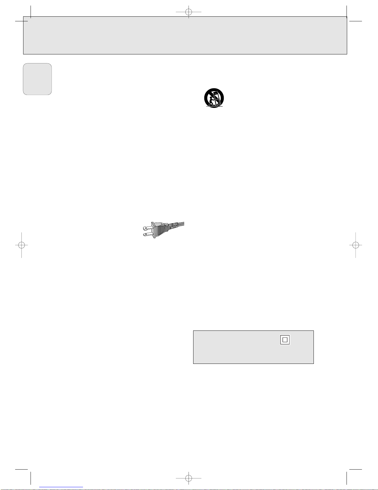
9. Do not defeat the safety
purpose of the polarized or grounding-type plug. A
polarized plug has two blades
with one wider than the other. A
grounding type plug has two
blades and a third grounding
prong. The wide blade or the third
prong are provided for your safety.
If the provided plug does not fit
into your outlet, consult an electrician for replacement of
the obsolete outlet.
10. Protect the power cord from being walked on or
pinched, particularly at plugs, convenience receptacles,
and the point where they exit from the apparatus.
11. Only use attachments/accessories specified by the
manufacturer.
12. Use only with the cart, stand, tripod,
bracket, or table specified by the
manufacturer or sold with the apparatus.
When a cart is used, use caution when
moving the cart/apparatus combination to
avoid injury from tip-over.
13. Unplug this apparatus during lightning storms or when
unused for long periods of time.
14. Refer all servicing to qualified service personnel.
Servicing is required when the apparatus has been
damaged in any way, such as power-supply cord or plug
is damaged, liquid has been spilled or objects have fallen
into the apparatus, the apparatus has been exposed to
rain or moisture, does not operate normally, or has been
dropped.
15. Battery usage CAUTION – To prevent battery leakage
which may result in bodily injury or damage to the unit:
● Install all batteries correctly, + and - as marked on the
unit.
● Do not mix batteries (old and new or carbon and
alkaline, etc.).
● Remove batteries when the unit is not used for a
long time.
EL 6475-E003: 01/6
Class II equipment symbol
This symbol indicates that the unit has a double
insulation system.
AC Polarized
Plug
IMPORTANT SAFETY INSTRUCTIONS
MFX450_eng 11/26/02 3:21 AM Page 4
Page 6
5
English
GENERAL INFORMATION
This receiver is supplied including:
– a remote control
– 2 batteries for the remote control, size AA
– a coaxial cable for audio connection with a DVD player
– a coaxial cable for the CINEMA LINK connection
– a loop antenna
– a wire antenna
– this instruction booklet
If you have stacked the components of your system, the
receiver must be on top. Place the receiver on a flat,
hard, stabile surface. Do not cover any vents and leave
50 cm (20 inches) above and 10 cm (4 inches) to the left
and right of the receiver clear for ventilation.
For good reception the loop antenna should not be placed on
top of or beneath VCRs, CD recorders, DVD players, TVs and
other radiation sources.
All redundant packing material has been omitted. We have
tried to make the packaging easy to separate into three single
materials: cardboard (box), polystyrene foam (buffer) and
polyethylene (bags, protective foam sheet).
Your set consists of materials which can be recycled if
disassembled by a specialized company. Please observe the
local regulations regarding the disposal of packing materials,
dead batteries and old equipment.
Manufactured under license from Dolby Laboratories. “DOLBY”,
“DOLBY DIGITAL”, “PRO LOGIC” and the double-D symbol 2
are trademarks of Dolby Laboratories. Confidential unpublished
works. © 1992–1997 Dolby Laboratories. All rights reserved.
“DTS” and “DTS Digital Surround” are trademarks of Digital
Theater Systems, Inc. Copyright 1996 Theater Systems, Inc.
All Rights Reserved.
Trademark acknowledgement
Environmental information
Setup
Scope of supply
Safety instructions
Safety instructions ......................................................................2 & 4
General information
Scope of supply..................................................................................5
Setup ..................................................................................................5
Environmental information.................................................................5
Trademark acknowledgement............................................................5
Controls .................................................................................................6
Remote control
Remote control use............................................................................7
Remote control buttons .....................................................................8
Connectors............................................................................................9
Connections
Analog audio connections ...............................................................10
Digital audio connections ................................................................11
System control bus, CINEMA LINK .................................................12
Video connections............................................................................12
Power ...............................................................................................13
Speaker connections........................................................................13
TV as the center speaker.................................................................13
Antenna connections .......................................................................13
System setup
Positioning the speakers..................................................................14
Speaker setup and testing...............................................................14
Power handling ................................................................................14
Headphones .....................................................................................14
Maintenance ....................................................................................14
Receiver adjustment ........................................................................15
Display.................................................................................................16
Menus
Receiver menu ...........................................................................17–18
TV menu ...........................................................................................18
Activating CINEMA LINK .................................................................18
Source selection
SOURCE SELECT...............................................................................19
6 CHANNEL-DVD/SACD INPUT selection .......................................19
Reassigning a source selection .......................................................19
Using one source selection for two or more appliances ................19
About 6 CHANNEL-DVD/SACD INPUT ............................................19
Playback, recording
Playing a source...............................................................................20
Adjusting the sound.........................................................................20
Recording from a source..................................................................20
Recording from the digital output ...................................................20
Surround sound
About surround sound......................................................................21
Switching surround sound ...............................................................21
Surround sound settings..................................................................22
Tuner
Tuning to radio stations...................................................................23
Switching FM sensitivity .................................................................23
Storing radio stations ......................................................................23
Tuning to stored radio stations........................................................24
Resorting stored radio stations .......................................................24
Naming radio stations .....................................................................24
Clearing station names....................................................................24
Technical data
Receiver............................................................................................25
Troubleshooting
Warning............................................................................................26
Troubleshooting................................................................................26
Limited warranty
Limited warranty ..............................................................................27
As an ENERGY STAR®partner, Magnavox has determined
that this product meets the ENERGY STAR
®
guidelines for energy efficiency.
MFX450_eng 11/26/02 3:21 AM Page 5
Page 7
6
English
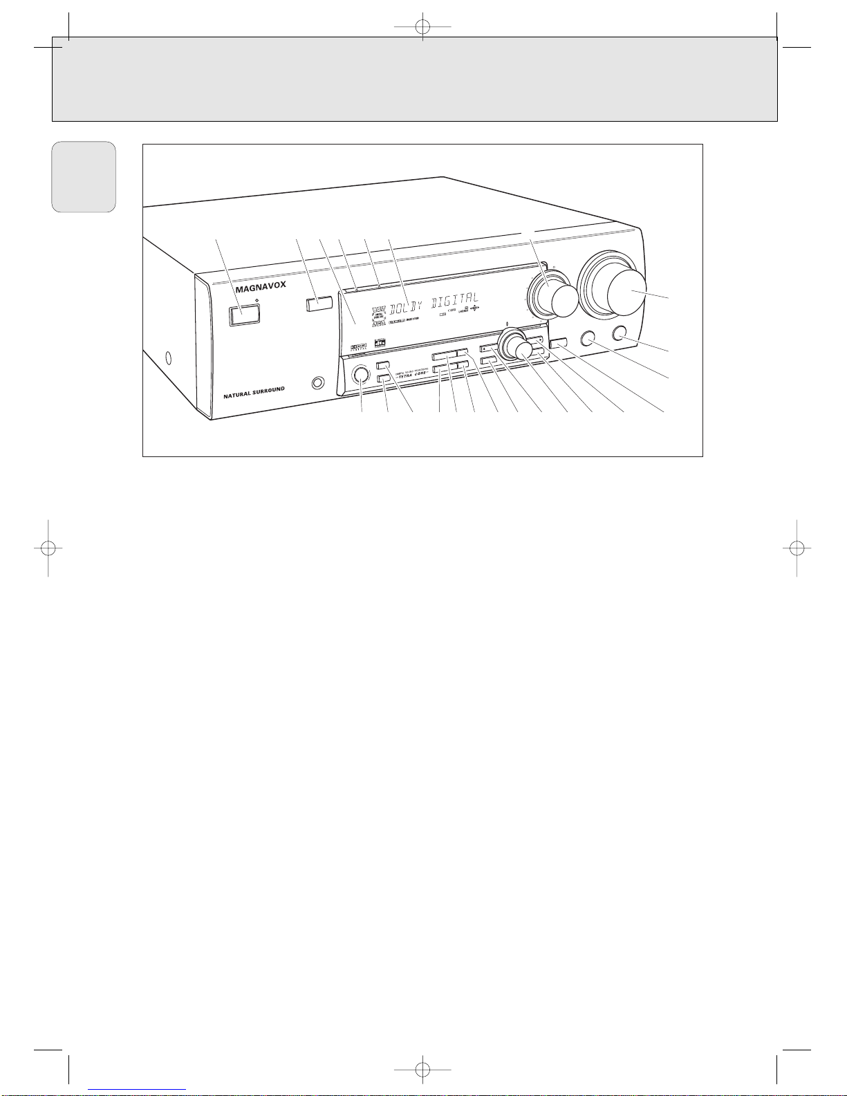
CONTROLS
1 POWER / STANDBY.......Switches the receiver on and off.
2 CINEMA LINK ................Switches on and off the system
control bus between the receiver
and the TV.
3 ..........................................Sensor for the infrared remote
control.
4 VIRTUAL..........................Control light for virtual surround
5 HALL ................................Control light for HALL.
6 ..........................................Display
7 SOURCE SELECT............Selects the different audio and
video connectors.
Reactivates the receiver from
standby.
8 VOLUME..........................Increases and decreases the
volume level.
9 TREBLE............................Adjusts the treble when used in
combination with VOLUME.
0 BASS ...............................Adjusts the bass when used in
combination with VOLUME.
! LOUDNESS .....................Switches LOUDNESS on and off.
@ NEXT 2 ...........................TUNER: searches radio stations.
MENU: switches to the next
menu level.
# ENTER / OK.....................Confirms selected menu values.
$ TUNER PRESET X MENU NAVIGATOR
TUNER: switches to the next and
previous stored radio station.
MENU: moves upwards and
downwards.
% 1 PREV. / EXIT TUNER: searches radio stations.
MENU: switches to the previous
menu level.
^ SETUP MENU ................Switches the menu on and off.
& SENS. ..............................Switches between low and high
tuner sensitivity.
* DISPLAY..........................Switches the brightness of the
display.
( TUNER BAND ................Switches the wavebands of the
tuner.
) NAME/FREQUENCY ......Switches between name and
frequency display.
¡ SURR. MODE..................Switches through the different
speaker configurations.
™ VIRTUAL MODE .............Scrolls through the different
virtual surround sound modes
£ SURROUND ON/OFF .....Switches between the last
selected surround mode and
stereo.
P
O
W
E
R
/ S
T
A
N
D
B
Y
CINEMA LINK
PHO
NES
DIGITAL CINEMA SOUND CENTER
LOUDNESS
BASS
TREBLE
S
O
U
R
C
E
S
E
L
E
C
T
O
R
D
V
D
V
O
L
U
M
E
PHONO
T
U
N
E
R
CD
C
D
R
/
T
A
P
E
T
V
V
C
R
S
A
T
MENU
NA
VIGA
TOR
TUNER
PRESET
VIRTU
AL
H
ALL
S
U
R
R
O
U
N
D
S
U
R
R
.
M
O
D
E
3
D
S
U
R
R
O
U
N
D
T
U
N
E
R
B
A
N
D
N
A
M
E
/F
R
E
Q
U
E
N
C
Y
S
E
N
S
.
D
IS
P
L
A
Y
P
R
E
V
. /
E
X
I
T
S
E
T
U
P
M
E
N
U
N
E
X
T
T
E
R
/
O
K
O
N
/
O
F
F
1 234 56 7
8
9
0
!@#$^&*()¡™£
%
MFX450_eng 11/26/02 3:21 AM Page 6
Page 8
7
English
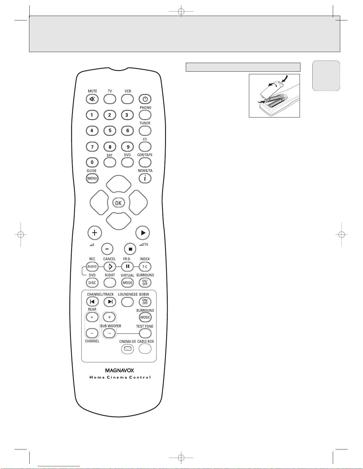
REMOTE CONTROL
Open the battery compartment
of the remote control and insert
2 alkaline batteries, type AA
(R06, UM-3).
Remove batteries if they are
dead or if the remote control
will not be used for a long time.
Batteries contain chemical substances, so they should
be disposed of properly.
The buttons on the remote control work the same way as the
corresponding ones on the receiver.
Important!
You have to press a source button for longer than 1 second to
switch the sound source on the receiver. Pressing a source
button for less than 1 second will only switch the remote
control to use the commands for the selected product.
The remote control remains tuned to the selected source until
another source button on the remote control is pressed. This
enables you to operate additional sources (i. e. winding a
tape) without changing the source on the receiver.
Remote control use
MFX450_eng 11/26/02 3:21 AM Page 7
Page 9

8
English
REMOTE CONTROL
H MUTE .....................Mutes the sound of the receiver in all
modes, except TV.
Mutes the sound of your Philips TV set
if your remote control is in TV mode.
2 ................................Switches the source selected on your
remote control (e.g. VCR, TV) to standby.
When pressed longer than 2 seconds,
the receiver switches to standby.
PHONO, TUNER, CD,
CDR/TAPE, TV,
VCR, SAT, DVD..............Switches the remote control to the
commands of the different products.
Selects the sources if pressed longer
than 1 second. SAT only works with
digital satellite receivers.
Reactivates the receiver from standby.
1–0................................Keys in numbers for tracks, stations or
frequencies. Numbers consisting of
two figures must be keyed in within
2 seconds.
CINEMA GO..........
Activates CINEMA LINK on the TV.
CABLE BOX...................Switches the remote control to the
cable box codes.
MENU GUIDE ..............TUNER: Switches the receiver menu
on and off.
DVD, TV: Switches the DVD/TV menu
on and off.
OK .................................Confirms menu options.
Arrow buttons ..............TUNER: Moves in the menus.
Right/left arrows are tuning up/down.
CD, CDR: Left/right arrows are
searching backwards/forwards,
up/down arrows are selecting the
next/previous track.
+A...........................Increases the receiver volume.
-A...........................Decreases the receiver volume.
i NEWS/TA.................TUNER: Without function.
TV: Switches teletext on and off.
SAT: Switches the information text on
and off.
ÉATV ......................Increases the TV volume.
CD, CDR, VCR, DVD: Starts playback.
ÇATV ......................Decreases the TV volume.
CD, CDR, VCR, DVD: Stops playback.
í
CHANNEL/TRACK
...Selects the previous preset tuner
station.
VCR: Rewinds the tape.
CD, CDR, DVD: Selects the previous
track.
TV: Selects the previous channel.
ë
CHANNEL/TRACK
...Selects the next preset tuner station.
VCR: Fast forwards the tape.
CD, CDR, DVD: Selects the next track.
TV: Selects the next channel.
LOUDNESS ...................Switches LOUDNESS on and off.
SUBW. ON/OFF ............Switches the subwoofer on and off
REC, DVD AUDIO..........CDR, VCR: Starts recording.
DVD: Switches audio tracks.
CANCEL, DVD ...........CD, CDR, SAT, VCR: Clears a
program, cancels selections.
DVD: Switches the view angle.
FR.D., DVD Å .............TUNER: Switches to FREQUENCY
DIRECT.
CD, CDR, VCR, DVD: Pauses
playback.
INDEX, DVD T-C............VCR: Switches the index search on
and off.
SAT: Switches the themes on and off.
DVD: Switches between title and
chapter.
DISC..............................CD-, CDR-, DVD-Changers:
Switches to the next disc.
NIGHT ...........................Switches NIGHT MODE on and off.
VIRTUAL MODE ............Scrolls through the different virtual
surround sound modes.
SURROUND ON/OFF ....
Switches SURROUND SOUND on and off.
+/- SUBWOOFER...Increases/decreases the subwoofer
volume.
+/- REAR ...............Increases/decreases the volume of the
rear speakers. While test tone is on,
the volume of the speakers you are
hearing can be increased/decreased
with these buttons.
SURROUND MODE.......Scrolls through the different surround
modes.
TEST TONE ...................Switches the test tone on and off.
While test tone is on, the volume of
the speakers you are hearing can be
increased/decreased with
+/- REAR.
Remote control buttons
MFX450_eng 11/26/02 3:21 AM Page 8
Page 10
9
English
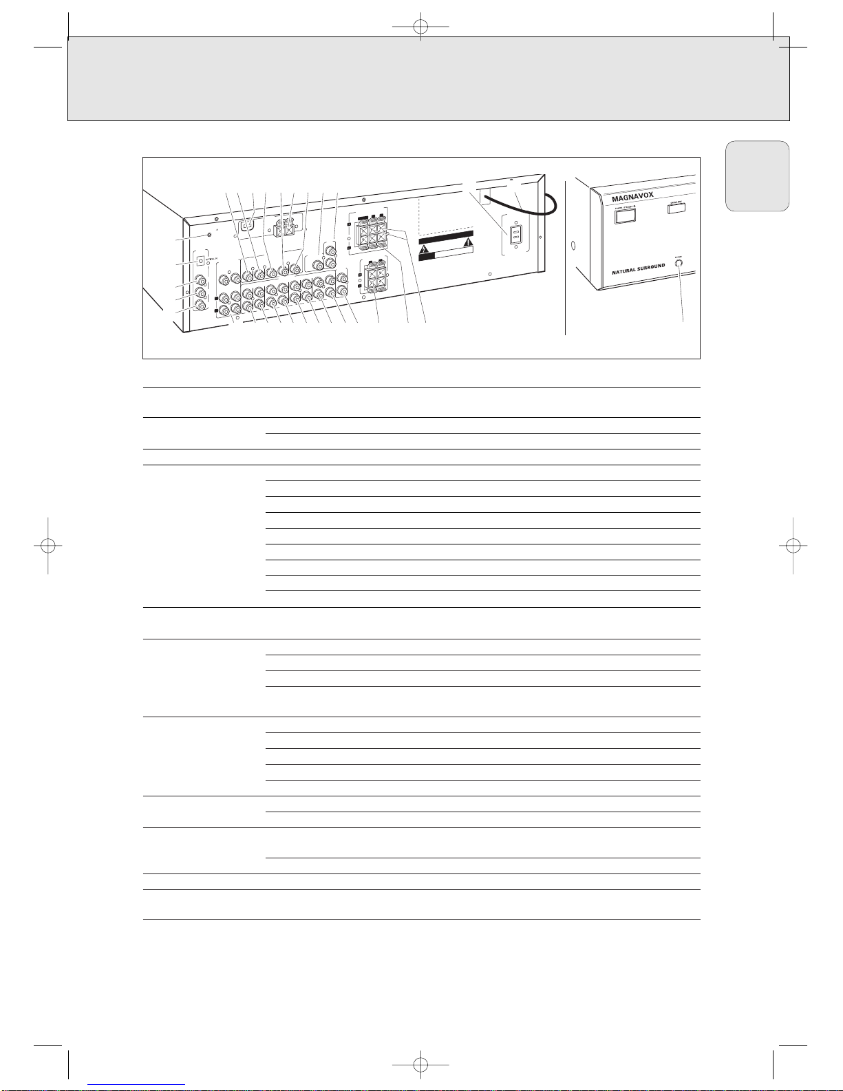
CONNECTORS
Connectors Connectors name Connect to:
6.3 mm headphone jack 1 PHONES A headphone with a 6.3 mm plug.
at the front.
FRONT SPEAKERS 2 R, L Right and left front speaker.
3 CENTER Center speaker.
SURROUND SPEAKERS 4 R, L Right and left surround speaker.
AUDIO IN/OUT 6 CDR/TAPE OUT Input of a CD recorder or a tape deck.
7 CDR/TAPE IN Output of a CD recorder or a tape deck.
8 CD IN Output of a CD player.
9 SAT IN Output of a satellite system.
0 VCR OUT Input of a video recorder.
! VCR IN Output of a video recorder.
@ TV IN Output of a TV.
# PHONO IN Output of a turntable with MM coil.
( PHONO GND f Ground cable of a turntable.
6 CHANNEL-DVD/ $
6 CHANNEL-DVD/
6 channel output of appliances such as DVD or laserdisc players.
SACD INPUT
SACD INPUT
DIGITAL AUDIO IN/OUT % COAX 1 IN Coaxial output of digital appliances (default input for source DVD).
^ COAX 2 IN Coaxial output of digital appliances.
& COAX OUT Coaxial input of digital appliances such as CD recorders or MD recorders.
* OPTICAL IN Optical output of digital appliances such as DVD players, CD players,
CD recorders or MD players.
VIDEO IN/OUT ) DVD IN Output of a DVD player.
¡ MON OUT Input of a monitor (e. g. the TV).
£ VCR IN Output of a video recorder.
≤ VCR OUT Input of a video recorder (for recording).
§ SAT IN Output of a satellite system.
Antenna connectors ™ AM LOOP Frame antenna supplied.
∞ FM 300 Ω Wire antenna supplied or exterior antenna.
Preamplified outputs 5 CENTER PRE-OUT Input of a TV when it is used as the center speaker (only possible
when the CINEMA LINK system bus is connected).
≥ SUBWOOFER PRE-OUT Input of a powered subwoofer.
System control bus • CINEMA LINK System control bus jacks of a Philips TV with CINEMA LINK.
Power outlets ª AC OUTLET Supplies same voltage as mains. Up to 120 W/1A total permitted load.
(not on all versions)
Power cord º After all other connections have been made, connect the
power cord to the wall outlet.
V
ID
EO
IN
/O
U
T
R
L
CENTER
CAUTION
R
IS
K
O
F
E
L
E
C
T
R
IC
S
H
O
C
K
D
O
N
O
T
O
P
E
N
AVIS
RISQUE DE CHOC ELECTRIQUE
NE PAS OUVRIR
D
esigned and deve
loped b
y Philips in th
e Europea
n
Community.
Manufactured under license from Dolby Laboratories.
”DOLBY
“, ”DOLBY DIGITAL“, ”PRO LOGIC“ and the
double-D Symbol are trademarks of Dolby Laboratories.
Confidential Unpublished Works.
©1992–1997 Dolby Laboratories. All righ
ts reserved.
Manufactured under license from Digital Theater
System
s. Inc. US Pat. No. 5,451,942 and other world-
w
ide patents issued and pending. ”DTS“ and ”DTS
Dig
ital Surround“ are trademarks of Digital Theater
Systems, Inc. Copyright 1996 Digital Theater Systems,
Inc. A
ll Rights Reserved.
L
R
P
H
O
N
O
G
N
D
.
IN
PLAY
IN
IN
OUT
REC
IN
PLAY
OUT
REC
C
O
A
X
O
U
T
F
M
300
Ω
D
IG
I
T
A
L
A
U
D
IO
IN
/
O
U
T
C
O
A
X
2
IN
P
H
O
N
O
V
C
R
T
V
S
A
T
C
D
C
D
R
/
T
A
P
E
A
U
D
IO
IN
/O
U
T
IN
IN
P
R
E
-
O
U
T
C
E
N
T
E
R
O
U
T
R
E
C
IN
P
LA
Y
D
VD
IN
M
O
N
O
U
T
VC
R
S
A
T
IN
S
U
B
W
O
O
F
E
R
P
R
E
-O
U
T
CINEMA
LINK
A
M
L
O
O
P
CEN
T
ER
SU
BW
.
C
O
A
X
1
IN
L
R
567890!@
ªº
•
#$
%
^
&
*
(
)¡™£≤∞§≥
SU
R
R.
FR
ON
T
A
N
T
E
N
N
A
AC OUTLET
120V - 60 Hz
1
2
0
W
/1
A
M
A
X
.
S
W
IT
C
H
E
D
S
U
R
R
O
U
N
D
S
PE
A
K
E
R
S
EA
C
H
SP
E
A
K
E
R
≥ 6
Ω
F
R
O
N
T
S
P
E
A
K
E
R
S
E
A
C
H
S
P
E
A
K
E
R
≥
6
Ω
6
C
H
A
N
N
E
L
/
D
V
D
S
A
-
C
D
I
N
P
U
T
234
1
MFX450_eng 11/26/02 3:21 AM Page 9
Page 11
10
English
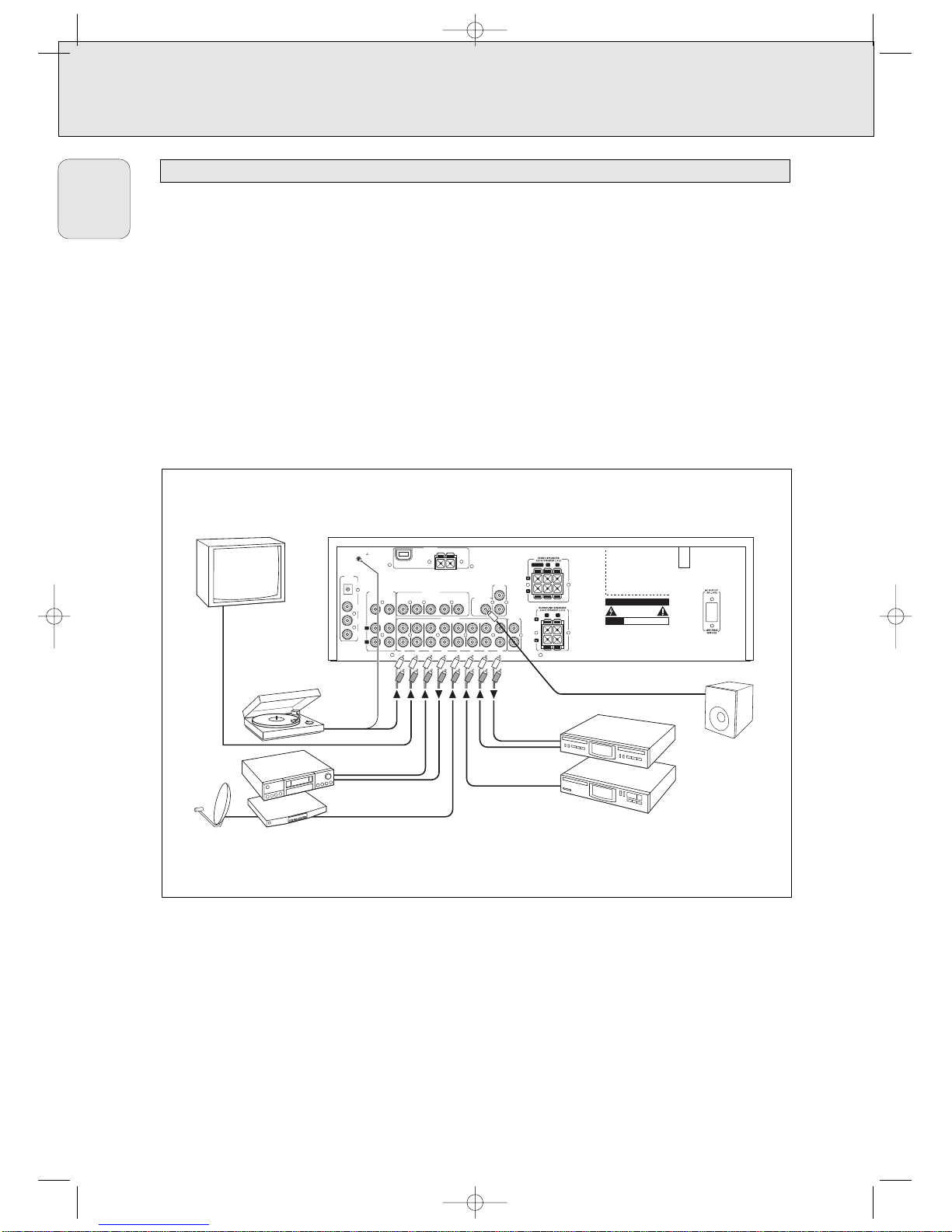
Analog audio connections
CONNECTORS
There are analog and digital connectors available on some
appliances. If possible use the digital connection; usually this
will result in better sound quality. See “Reassigning a source
selection” on how to use the digital connectors of the receiver.
Because of a different kind of output signal, the use of Dolby
Digital Laserdisc requires an optional AC-3 RF demodulator.
DTS Digital SurroundTMis a discrete 5.1-channel digital audio
format available on CD, LD, and DVD software which
consequently cannot be decoded and played back inside most
CD, LD, or DVD players. For this reason, when DTS-encoded
software is played back through the analog outputs of the CD,
LD, or DVD player, excessive noise will be exhibited. To avoid
possible damage to the audio system, proper precautions
should be taken by the customer if the analog outputs are
connected directly to the receiver.
To enjoy DTS Digital SurroundTMplayback, a DTS-compatible
player has to be connected to one of the digital inputs of the
receiver.
ANTENNA
DIGITAL
AUDIO
IN/OUT
PHONO
VCRTV SAT CD CDR/TAPE
AUDIO IN/OUT
IN IN
IN
PLAY
OUT
REC
IN IN
IN
PLAY
OUT
REC
PRE-OUT
CENTER
CAUTION
RISK OF ELECTRIC SHOCK
DO NOT OPEN
AVIS
RISQUE DE CHOC ELECTRIQUE
NE PAS OUVRIR
Designed and developed by Philips in the European
Community.
Manufactured under license from Dolby Laboratories.
”DOLBY“, ”DOLBY DIGITAL“, ”PRO LOGIC“ and the
double-D Symbol are trademarks of Dolby
Laboratories. Confidential Unpublished Works.
©1992–1997 Dolby Laboratories. All rights reserved.
Manufactured under license from Digital Theater
Systems. Inc. US Pat. No. 5,451,942 and other worldwide patents issued and pending. ”DTS“ and ”DTS
Digital Surround“ are trademarks of Digital Theater
Systems, Inc. Copyright 1996 Digital Theater Systems,
Inc. All Rights Reserved.
PHONO GND.
R
L
CENTER
R
L
AM LOOP
DVD
IN
MON
OUT
VCR
SAT
IN
PRE-OUT
CINEMA
LINK
SUBWOOFER
IN
PLAY
OUT
REC
COAX
OUT
COAX 2
IN
R
L
SURR.
CENTER SUBW.
FRONT
OPTICAL IN
FM 300 Ω
COAX 1
IN
2
ANTENNA
VIDEO IN/OUT
6 CHANNEL-DVD/
SA-CD INPUT
AUDIO
OUT
TURNTABLE
AUDIO IN
AUDIO OUT
IN
OUT
VCR
SAT RECEIVER
CD RECORDER
CD PLAYER
MONITOR / TV
POWERED
SUBWOOFER
MFX450_eng 11/26/02 3:21 AM Page 10
Page 12
11
English
CONNECTIONS
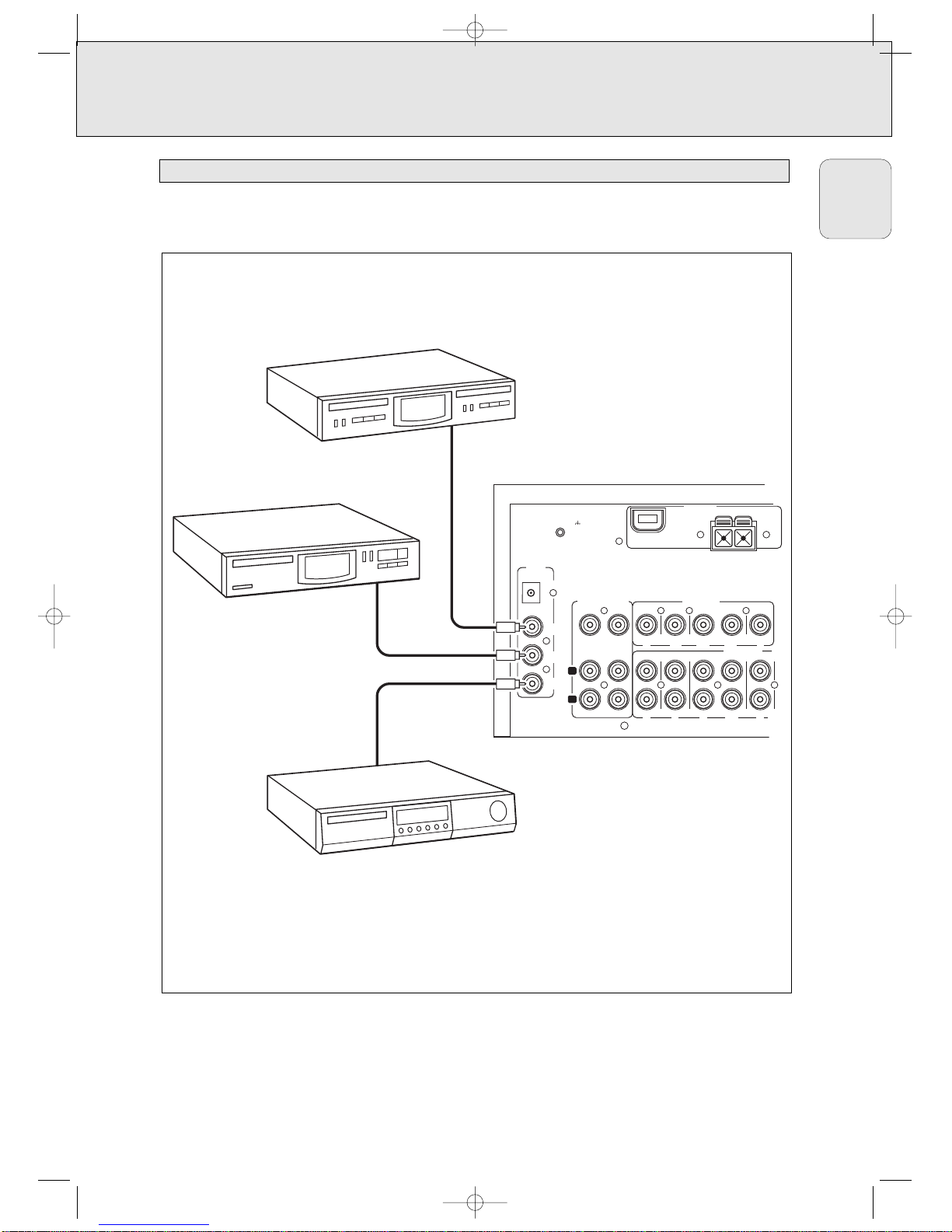
Digital audio connections
DIGITAL
AUDIO
IN/OUT
PHONO
VCRTV SAT
AUDIO IN/OUT
IN IN
IN
PLAY
OUT
REC
IN
PHONO GND.
AM LOOP
DVD
MON
VCR
SAT
COAX 1
IN
COAX 2
IN
R
L
SURR.
CENTER
SUBW.
FRONT
OPTICAL IN
FM 300 Ω
COAX
OUT
VIDEO IN/OUT
ANTENNA
CD RECORDER
CD PLAYER
DVD PLAYER
IN
OUT
IN
PLAY
IN
OUT
REC
6 CHANNEL /
DVD SA-CD INPUT
MFX450_eng 11/26/02 3:21 AM Page 11
Page 13
12
English
CONNECTIONS
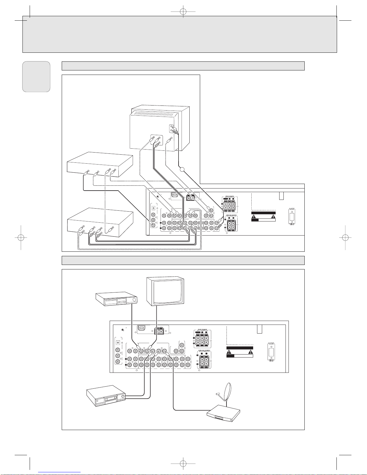
System control bus, CINEMA LINK
Video connections
ANTENNA
DIGITAL
AUDIO
IN/OUT
PHONO
VCRTV SAT CD CDR/TAPE
AUDIO IN/OUT
IN IN
IN
PLAY
OUT
REC
IN IN
IN
PLAY
OUT
REC
PRE-OUT
CENTER
CAUTION
RISK OF ELECTRIC SHOCK
DO NOT OPEN
AVIS
RISQUE DE CHOC ELECTRIQUE
NE PAS OUVRIR
Designed and developed by Philips in the European
Community.
Manufactured under license from Dolby Laboratories.
”DOLBY“, ”DOLBY DIGITAL“, ”PRO LOGIC“ and the
double-D Symbol are trademarks of Dolby
Laboratories. Confidential Unpublished Works.
©1992–1997 Dolby Laboratories. All rights reserved.
Manufactured under license from Digital Theater
Systems. Inc. US Pat. No. 5,451,942 and other worldwide patents issued and pending. ”DTS“ and ”DTS
Digital Surround“ are trademarks of Digital Theater
Systems, Inc. Copyright 1996 Digital Theater Systems,
Inc. All Rights Reserved.
PHONO GND.
R
L
CENTER
R
L
AM LOOP
DVD
IN
MON
OUT
VCR
SAT
IN
PRE-OUT
CINEMA
LINK
SUBWOOFER
IN
PLAY
OUT
REC
COAX
OUT
COAX 2
IN
R
L
SURR.
CENTER SUBW.
FRONT
6 CHANNEL-DVD/
SACD INPUT
OPTICAL IN
FM 300 Ω
COAX 1
IN
2
ANTENNA
VIDEO IN/OUT
VCR
VIDEO
IN
AUDIO
OUT
CINEMA LINK
VIDEO
OUT
D
IGITAL
O
UT
CIN
EM
A LIN
K
VIDEO
AU
D
IO
CIN
EM
A LIN
K
IN
/REC
OUT/PLAY
L
IN
REC
OU
T
PLA
Y
DVD PLAYER
TV
CENTER IN
R
A
ANTENNA
DIGITAL
AUDIO
IN/OUT
PHONO VCRTV SAT CD CDR/TAPE
AUDIO IN/OUT
IN IN
IN
PLAY
OUT
REC
IN IN
IN
PLAY
OUT
REC
PRE-OUT
CENTER
CAUTION
RISK OF ELECTRIC SHOCK
DO NOT OPEN
AVIS
RISQUE DE CHOC ELECTRIQUE
NE PAS OUVRIR
Designed and developed by Philips in the European
Community.
Manufactured under license from Dolby Laboratories.
”DOLBY“, ”DOLBY DIGITAL“, ”PRO LOGIC“ and the
double-D Symbol are trademarks of Dolby
Laboratories. Confidential Unpublished Works.
©1992–1997 Dolby Laboratories. All rights reserved.
Manufactured under license from Digital Theater
Systems. Inc. US Pat. No. 5,451,942 and other worldwide patents issued and pending. ”DTS“ and ”DTS
Digital Surround“ are trademarks of Digital Theater
Systems, Inc. Copyright 1996 Digital Theater Systems,
Inc. All Rights Reserved.
PHONO GND.
R
L
CENTER
R
L
AM LOOP
DVD
IN
MON
OUT
VCR
SAT
IN
PRE-OUT
CINEMA
LINK
SUBWOOFER
IN
PLAY
OUT
REC
COAX
OUT
COAX 2
IN
R
L
SURR.
CENTER SUBW.
FRONT
OPTICAL IN
FM 300 Ω
COAX 1
IN
2
ANTENNA
VIDEO IN/OUT
6 CHANNEL-DVD/
SACD INPUT
DVD PLAYER
MONITOR / TV
VIDEO IN
VIDEO OUT
VCR
SAT RECEIVER
If the receiver and Magnavox (or Philips) TV (or even
better in addition a Philips VCR or DVD player) with
Cinemalink are connected with the CINEMA LINK
system bus control, some extra system benefits are
offered:
– Upon starting a source, the system will
automatically switch to that input.
– You may control the system via the TV screen.
Depending on the language of the TV, this can be
done in your preferred language.
– The TV can function as the center speaker of your
system, making a separate center speaker
unnecessary.
(The cable A has to be purchased separately.)
– By pressing the standby button on the remote
control, you can switch the complete system to
standby.
MFX450_eng 11/26/02 3:21 AM Page 12
Page 14

13
English
CONNECTIONS
The type plate is located on the rear of the receiver.
1 Check whether the power voltage as shown on the type
plate corresponds to your local power voltage. If it does
not, consult your dealer or service organization.
2 Connect the power cord to the power outlet.
To disconnect the unit from the power completely, remove the
power plug from the power outlet.
Some of the speaker connections on the receiver are screw
connectors and some are click-fit connectors. Use them as
shown below.
1 Always connect the colored (or marked) wire to the colored
terminal and the black (or unmarked) wire to the black
terminal.
2 Connect:
– Left front speaker to L (red and black)
– Right front speaker to R (red and black)
– Center speaker to CENTER (blue and black)
– Left surround speaker to SURROUND L (grey and black)
– Right surround speaker to SURROUND R (grey and black)
You may use your Philips or Magnavox TV with CINEMA LINK
as the center speaker. For TV’s with cinch connectors,
additional cinch cables are needed. These cables must be
connected to the blue CENTER PRE-OUT connector on the
back. Look into the instruction manual of your TV on how to
use it as the center speaker.
AM (MW) antenna
The loop antenna supplied is for indoor use only. Position the
antenna as far away as possible from the receiver, a TV, the
cables, a DVD player, a VCR and other radiation sources.
1
Fit the plug of the frame antenna to AM LOOP as shown below.
2 Turn the antenna for optimum reception.
FM antenna
The wire antenna supplied can be used only to receive nearby
stations. For better reception we recommend using a cable
antenna system or an outdoor antenna.
1 Open the FM 300 Ω click-fits by pushing the lever down as
shown below.
2 Insert each wire of the antenna into one hole.
3 Close the click-fits using the lever.
4
Move the antenna in different positions for optimum reception.
The unit complies with the FCC-Rules, Part 15.
Operation is subject to the following two conditions:
1. This device may not cause harmful interference, and
2. This device must accept any interference received,
including interference that may cause undesired
operation.
8 mm
1
2
3
AM
LO
O
P
ANTENNA
Antenna connections
TV as the center speaker
8 mm
1
2
3
Speaker connections
Power
MFX450_eng 11/26/02 3:21 AM Page 13
Page 15
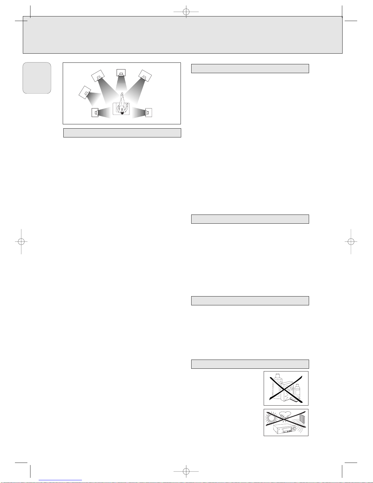
General hints for positioning
Avoid positioning the speakers in a corner or on the floor as
this will boost the bass tones too much. Placing the speakers
behind curtains, furniture, etc. will reduce the treble
response. The listener should always be able to ”see” the
speakers.
Each room has different acoustic characteristics and the
positioning possibilities often are limited. You can find the
best position for your speakers by referring to the picture
above.
As a minimum we recommend 5 speakers (2 front, a center,
2 surround) for good surround sound. It is possible to
reproduce some kind of surround sound with fewer speakers.
This is done by redirecting the signals which are foreseen for
the missing speakers to the existing ones. See “Menus” on
how to set up the receiver correctly for the number and size
of the speakers used.
Positioning the front speakers
The front speakers should be placed to the right and left in
front of the listening position like usual stereo speakers.
Positioning the center speaker
The center speaker should be placed in the center between
the two front speakers, e. g. underneath or on top of the TV.
The best height for the center speaker is the height of the
listener’s ears (while seated).
Positioning the surround speakers
The surround speakers should face each other and be in line
with, or slightly behind the listener.
Positioning the subwoofer
A subwoofer can be used to enhance the bass performance of
your system dramatically. The subwoofer can be positioned
anywhere in the room, because it is not possible to locate the
source of deep tones. Nevertheless, you should not place the
subwoofer in the middle of a room, since the bass could be
severely weakened. Do not place any object on the
subwoofer.
The relative volume of the speakers must be adjusted for
optimal surround sound. You should be at your usual listening
position when adjusting the speaker volume. See “Receiver
menu” on how to unit up the receiver for the used speakers.
Ideally, the volume in the listening position should be the
same from all speakers.
1 Press POWER / STANDBY to switch on the receiver.
2 Press TEST TONE on the remote control.
y A test tone coming from the different speakers, except
the subwoofer, is heard.
3 Press +/- REAR on the remote control to
increase/decrease the volume of the actual speaker. The
best result is achieved when all speakers have equal
volume in the listening position.
4 Press TEST TONE on the remote control.
y The test tone stops.
Note: If you are not completely satisfied with the volume
settings, we recommend making minor adjustments to
them during surround sound playback.
If the receiver is used at very high power it can produce
distortions which may damage your speakers seriously. If
distortions occur, reduce the volume and the tone controls to
a level where the sound is acceptable again.
To avoid overheating of the unit a safety circuit has
been built in. Therefore your set may disconnect under
extreme conditions. If this happens, switch the unit off
and let it cool down before reusing it. After having let
the set cool down switch the set on again and select
the desired source by turning SOURCE SELECT.
Connecting headphones to PHONES will switch off the
speakers. The receiver switches to STEREO and surround
sound will be reduced to a stereo signal which is reproducible
by standard headphones.
Disconnecting the headphones switches on the speakers
again. If you wish to enjoy surround sound again, switch the
receiver back to surround sound.
Clean the receiver with a soft,
slightly dampened, lint-free cloth. Do
not use any cleaning agents as they
may have a corrosive effect.
Do not expose the receiver to
humidity, rain, sand or excessive heat
(caused by heating equipment or
direct sunlight).
Maintenance
Headphones
Power handling
Speaker setup and testing
Positioning the speakers
SYSTEM SETUP
14
English
SUBWOOFER
SURROUND
(REAR)
LEFT
LEFT
RIGHT
CENTER
FRONT
RIGHT
FRONT
SURROUND
(REAR)
MFX450_eng 11/26/02 3:21 AM Page 14
Page 16
15
English
SYSTEM SETUP
Once the number and position of loudspeakers has been
fixed, you can adjust the initial receiver settings for optimum
surround sound with the actual setup:
1 Set which speakers have been connected to the receiver
(see “Menus / SPEAKR SETUP”).
Note: The initial setting of your receiver is:
two front speakers left and right: present
(cannot be altered)
center speaker: present
two rear speakers: present
subwoofer: present
2 Select the size of the speakers (SMALL or LARGE)
(see “Menus / SPEAKR SIZES”).
Select SMALL if your speaker is able to reproduce low
notes down to at least 80–100 Hz.
Select LARGE if your speaker is able to reproduce low
notes down to at least 50 Hz.
(As a rule of thumb, a LARGE speaker has a cone diameter
of at least 12 cms (5 inches).)
See the specification sheets of your loudspeakers.
Note: The initial setting of your receiver is:
all speakers: SMALL
3 Set the distance from the speakers to the listener’s position
(see “Menus / SPK DISTANCE”).
Note: The initial setting of your receiver is:
front speakers, left and right: 13 feet (4 meters)
center speaker: 10 feet (3 meters)
rear speakers, left and right: 7 feet (2 meters)
Receiver adjustment
MFX450_eng 11/26/02 3:21 AM Page 15
Page 17
16
English
DISPLAY
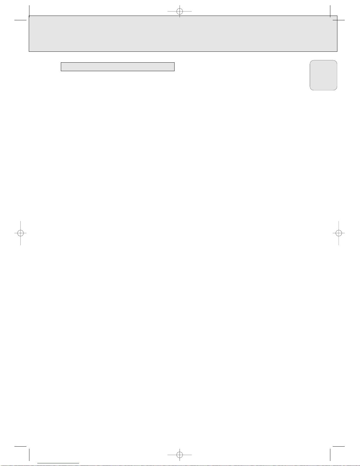
The display of the receiver is divided into 4 sections, which
are to be used for the following:
Speaker diagram
A rectangle with a letter in it shows that a speaker has been
selected in the setup menu. However, the subwoofer indicator
will only light when a subwoofer signal is available. If only a
letter is shown, this speaker is not used and its sound is
being reproduced by the other speakers.
.....virtual surround sound
SURROUND.................surround sound is reproduced
DIGITAL SURROUND ....digital surround sound is reproduced
L, R ...........................front left and right speaker
C...............................center speaker
SL, SR .......................surround speakers
SW............................subwoofer
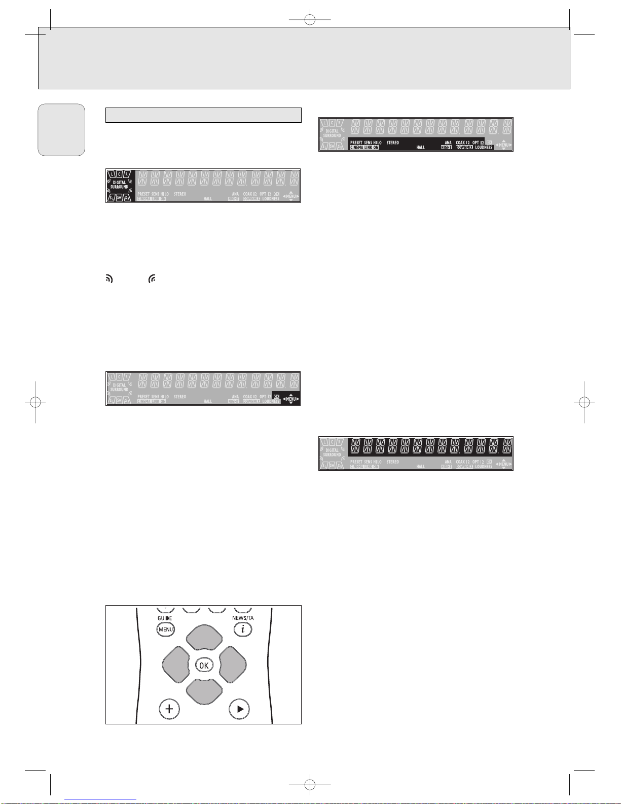
Menu indication
These signs show you if the menu is on or off and indicate in
which direction you may move.
MMEENNUU .......................Menu is on.
1..............................You may move backwards to the previous
menu topic using 1 PREV. / EXIT (“left”
key on the remote control).
3 .............................You may move up in an option list using
X MENU NAVIGATOR (“up” key on the
remote control).
4 .............................You may move down in an option list
using X MENU NAVIGATOR (“down” key
on the remote control).
2..............................You may move forward to the next menu
topic using NEXT 2 (“right” key on the
remote control).
OOKK.............................You may confirm the displayed value.
Status lights
Signs show you various settings and information about the
status of the receiver.
PRESET ......................Tuner is tuned to a preset radio station.
SENS HI.....................Tuner is switched to high sensitivity.
SENS LO ..................Tuner is switched to low sensitivity.
CCIINNEEMMAA LLII NN KK OONN ......CINEMA LINK is active
STEREO......................An FM station is being received in stereo.
SMART SOUND ...........One of the preset sound settings of the
receiver is being used.
HALL..........................HALL effect is on.
ANA ..........................Analog input is being used for the playing
source.
NNIIGG HHTT
.......................NIGHT MODE is on.
COAX 1 ......................Coaxial digital input COAX 1 is being
used for the playing source.
COAX 2 .....................Coaxial digital input COAX 2 is being
used for the playing source.
DDOOWWNNMMIIXX.................Incoming multichannel signals are being
reduced to fewer output signals
(depending on the number of speakers).
OPT ...........................Optical digital input OPTICAL IN is being
used for the playing source.
LOUDNESS .................LOUDNESS is switched on.
Information area
This area is used for feedback of the receiver, tuner
frequencies, menu options, values and scrolling text
messages.
Display
MFX450_eng 11/26/02 3:21 AM Page 16
Page 18

17
English
MENUS
The receiver is equipped with a menu system. The menu is
used for the setup of the receiver. The different menu options
are related to each other in a logical way. Let’s assume you
have no center speaker connected, and so you switched
CENTER SPEAKR to NO. If you try to use VOL CENTER,
a message will be scrolled that this is not possible
(INSTALL CENTER SPEAKER).
The menu always works the same way. Arrows in the display
show you the possible moving directions.
1 Press SETUP MENU.
yMENU, and * EFFECTS is displayed.
• You can exit the menu at any time by pressing
SETUP MENU.
2 Turn X MENU NAVIGATOR until the desired option (or a
value) is displayed.
3 Press NEXT 2 to choose the displayed option (or
ENTER / OK to confirm a value).
• You can leave any option (values remain unchanged) by
pressing 1 PREV. / EXIT.
Menu structure
* EFFECTS
Switches sound effects.
VIRT SURR
virtual surround: 0…100 %
* VOL BALANCE
Adjusts the relative volume balance between the
connected speakers.
TEST TONE
Test tone: on/off
VOL FRONT-L
Volume front left speaker: –50…+50
VOL FRONT-R
Volume front right speaker: –50…+50
VOL CENTER
Volume center speaker: –50…+50
VOL REAR-L
Volume rear left speaker: –50…+50
VOL REAR-R
Volume rear right speaker: –50…+50
VOL SUBWOOFER
Volume subwoofer: –50…+50
Note: When using the 6 CHANNEL-DVD/SACD INPUT the
values below cannot be changed.
* SPEAKR SETUP
Selects the used speakers.
SUBW PRESENT
Subwoofer present: yes/no
CENTER SPEAKR
Center speaker present: yes/no
REAR SPEAKER
Rear speakers present: yes/no
* SPEAKR SIZES
Chooses the speaker sizes of the used speakers, for
optimal sound reproduction. LARGE indicates a speaker
which can reproduce frequencies lower than 50 Hz. If
SUBW PRESENT is set to NO, FRONT SIZE can only
be set to LARGE. If FRONT SIZE is set to SMALL,
CENTER SIZE can only be set to SMALL and
consequently a subwoofer must be connected.
SUBW PRESENT
Subwoofer present: yes/no
FRONT SIZE
Left and right front speakers: small/large
CENTER SIZE
Center speaker: small/large
REAR SIZE
Rear speakers: small/large
* SPK DISTANCE
Distance between the usual listening position and the
speakers. This defines the delay time for the surround sound.
DISTANCE L/ R
Distance to front speakers: 1…10 m (3…30 ft)
DISTANCE CNTR
Distance to center speaker: 1…10 m (3…30 ft)
DISTANCE REAR
Distance to rear speakers: 1…10 m (3…30 ft)
Receiver menu
MFX450_eng 11/26/02 3:21 AM Page 17
Page 19

18
English
MENUS
* SELECT INPUT
Assigns the audio input connectors to the different source
selections chosen with SOURCE SELECT (see “Source
selection” for details).
COAX1
Digital coaxial input 1, COAX 1 IN
COAX2
Digital coaxial input 2, COAX 2 IN
OPT
Digital optical input, OPTICAL IN
SAT IN
Analog audio input SAT IN
VCR IN
Analog audio input VCR IN
TV IN
Analog audio input TV IN
CDR IN
Analog audio input CDR IN
CD IN
Analog audio input CD IN
6 CH IN
Analog audio input 6 CHANNEL-DVD/SACD INPUT
* TUNER
Setup for preset radio stations (see “TUNER” for details).
AUTO INSTALL
Stores radio stations automatically
MAN INSTALL
Stores radio stations manually
GIVE NAME
Allows you to assign names to stored radio stations
RESHUFFLE
Resorts stored radio stations
If the receiver is connected to a Magnavox (or Philips)
CINEMA LINK TV via the CINEMA LINK system control bus
jacks (see “CONNECTIONS”), you may use the TV to set up
the system. An option called RECEIVER will be added to the
TV menu.
If CINEMA LINK is on, adjustments on the receiver will be
shown on the TV screen for a few seconds. Consult the
instruction booklet of your TV on how to use the TV menu.
The options offered may vary by TV model.
Switching the connection
• Press CINEMA LINK on or off to switch the connection
between the receiver and the TV.
yIf the connection is switched on, CINEMA LINK ON is
displayed.
Note: We recommend switching CINEMA LINK off during
recording. This avoids unwanted interruptions due to
switching TV functions.
If CINEMA LINK is switched on and the TV menu is active,
TV MENU is displayed and the menu and sound functions on
the receiver are locked.
• Press
CINEMA GO on the remote control.
y
The TV sends a play command to the CINEMA LINK DVD
player, if present. The DVD player will start playing and the
receiver automatically switches to the best CINEMA LINK
sound.
•
If no DVD player is connected or if the DVD player has no disc
loaded, the TV will send a play command to the CINEMA LINK
video recorder, if present.
y
The video recorder will start playing and the audio receiver
selects the best CINEMA LINK sound.
•
If no video recorder source is connected or tape is loaded, the
TV will select the last watched TV channel.
Activating CINEMA LINK
TV menu
MFX450_eng 11/26/02 3:21 AM Page 18
Page 20

19
English
SOURCE SELECTION
When selecting a source by turning SOURCE SELECT, the
audio and video inputs with the corresponding name are
activated. The incoming signal is reproduced by all audio and
– if the source includes a video signal – video outputs of the
receiver. It is possible to reassign a source selection to other
than these standard inputs.
Source selected........Connectors used
DVD...............................COAX 1 digital audio input and
DVD IN video input
PHONO..........................PHONO IN audio input
TUNER ..........................The tuner part of the receiver is used,
all inputs are switched off.
CD .................................CD IN audio input
CDR/TAPE.....................CDR/TAPE IN audio input
TV..................................TV IN audio input and
no video input
VCR ...............................VCR IN audio input and
VCR IN video input
SAT ...............................SAT IN audio input and
SAT IN video input
The 6 CHANNEL-DVD/SACD INPUT connectors can be
assigned to any of the available sources (excluding TUNER
and PHONO). The assignment can be done via the *
SELECT INPUT option in the menu. See below for more
details.
If a source is selected with SOURCE SELECT the standard
audio input is used. To change this, the source selection must
be reassigned to another audio input.
Example: Reassigning CD from the analog CD IN audio input
to the digital COAX 2 IN audio input.
1 Choose * SELECT INPUT from the menu and press
NEXT 2.
2 Turn SOURCE SELECT to select the source which should be
reassigned (e. g. CD).
yThe name of the source is displayed and the light of the
source flashes.
3 Turn X MENU NAVIGATOR to select the input connectors
which should be used (e. g. CD - COAX2).
4 Press ENTER / OK to confirm your selection.
ySTORED is displayed briefly.
5 This source selection is now using the chosen audio input
(e. g. CD uses the COAX 2 IN input connectors, COAX 2
lights when switching to CD).
You may assign more than one source to a source selection.
This can be useful when products are connected one after the
other in a chain.
Example: A VCR is connected to the TV but only the TV is
connected to the receiver. Both SOURCE SELECT
settings, TV as well as VCR, have to use the TV
input connectors.
1 Choose * SELECT INPUT from the menu and press
NEXT 2.
2 Turn SOURCE SELECT to select the source which should be
reassigned (e. g. VCR).
yThe name of the source is displayed and the light of the
source flashes.
3 Turn X MENU NAVIGATOR to select the input connectors
which should be used (e. g. VCR - TV IN).
4 Press ENTER / OK to confirm your selection.
ySTORED is displayed briefly.
5 This source selection is now using the chosen audio input (e.
g. VCR uses the TV IN input connectors, VCR TV IN is
displayed briefly when switching to VCR).
The 6 CHANNEL-DVD/SACD INPUT can be used to connect a
device with a built-in multichannel decoder (e.g. Dolby Digital,
DTS, etc.) and 6-channel output connector, i. e. a high end
DVD/SACD player.
When using the 6 CHANNEL-DVD/SACD INPUT audio input,
the receiver works as a multichannel amplifier. The source
reproduces surround sound and sends it to the receiver
divided into the necessary channels. Therefore the
SURROUND ON/OFF, HALL and SURR. MODE button have no
effect since the provided signal is already multichannel.
From a source which is connected to the
6 CHANNEL-DVD/SACD INPUT audio input cannot be
recorded.
About 6 CHANNEL-DVD/SACD INPUT
Using one source selection for two or more
appliances
Reassigning a source selection
6 CHANNEL-DVD/SACD INPUT selection
SOURCE SELECT
MFX450_eng 11/26/02 3:21 AM Page 19
Page 21

20
English
PLAYBACK, RECORDING
1 Press POWER / STANDBY to switch on the receiver.
2 Turn SOURCE SELECT to select a source.
yThe name of the source is displayed.
3 Start playback of the source as usual.
• Turn VOLUME to adjust the volume.
yVOLUME and the volume level between 0 and 50 is
displayed.
1 Press BASS or TREBLE.
yBASS or TREBLE and the actual value are displayed
briefly. Then TURN VOLUME KNOB TO CHANGE is
scrolled.
2 Turn VOLUME to adjust the bass or treble.
yBASS or TREBLE and the actual value are displayed.
Note: If VOLUME is not turned within 5 seconds or if any
other control is used, the bass or treble adjustment is
switched off.
• If a subwoofer is connected, press SUBW. ON/OFF to
increase the bass performance.
Note: In case of digital surround sound, a subwoofer signal
will only be available when supported by the source
material.
• Press LOUDNESS to switch on or off loudness.
yLOUDNESS is displayed if loudness is on.
If you wish to record from a source you must select it with
SOURCE SELECT. The incoming signal is reproduced by all
audio and – if the source includes a video signal – video
outputs of the receiver. The sound settings do not affect the
recording.
1 Turn SOURCE SELECT to select the source you want to record
from.
yThe name of the source is displayed.
2 Prepare the desired recording appliance. It must be
connected to one of the outputs of the receiver.
3 Start recording on the recording appliance.
4 Start the playback of the source as usual.
Notes: – The audio and video signal of VCR IN is not
reproduced by VCR OUT. The same applies to the
audio signal of CDR/TAPE IN to CDR/TAPE OUT.
– We recommend not to use the digital output
COAX OUT of the receiver to record from an analog
source. Use the analog output CDR/TAPE instead.
– From a source which is connected to the
6 CHANNEL-DVD/SACD INPUT audio input cannot
be recorded.
It is possible to connect a digital recorder to the digital output of
the receiver. In this way, all signals coming from the digital
inputs can be recorded directly on the connected audio recorder.
The receiver will also convert all signals coming from the analog
inputs to the digital output.
The receiver can be used to record digitally a multichannel
surround sound audio signal (Dolby Digital or DTS) from, for
example, DVD to CD-R. The receiver will convert the digital
multichannel signal into a stereo signal without loss of relevant
sound information.
Notes: – When recording a Dolby Digital or DTS signal, each
track must be recorded individually.
– Digital recording is not possible when the digital
source material is copy-protected.
Recording from the digital output
Recording from a source
Adjusting the sound
Playing a source
MFX450_eng 11/26/02 3:21 AM Page 20
Page 22

21
English
SURROUND SOUND
Surround sound gives you a completely new listening
sensation. You will have the feeling of being in the middle of
the action, because sound is coming from everywhere around
you. Look out for TV broadcasts, audio and video tapes and
discs with the 3, 1 or marks which are
encoded for multichannel surround sound. You should prefer
Dolby Digital or DTS to get the most out of your receiver.
DTS is a premium multichannel surround sound system
available on DVD discs, laserdiscs and audio discs. Consult
your software dealer on the availability of DTS software in
your region.
Notice that DVD discs do not always carry full multichannel
surround. To be sure that a disc is multichannel encoded
consult your dealer.
Most ordinary stereo tapes and discs can be replayed using
surround sound settings with good results. If the reproduction
is distorted in surround mode, switch to normal stereo mode.
The availabilty of the various surround sound modes
described depends on the number of speakers used and the
incoming sound information.
With surround sound on, you can switch through the different
surround modes. Note that the possibilities are related to
speaker setup defined in the receivers menu.
If a digital surround signal is detected, the receiver will scroll
either DOLBY DIGITAL or DTS.
1 Press SURROUND ON/OFF to switch on the surround sound.
yThe surround mode in use is scrolled.
2 Press SURR. MODE repeatedly to listen to the different
surround modes (if available).
yThe chosen mode and the speakers used are displayed.
If the incoming multichannel signals are reduced to
fewer output signals, DOWNMIX is displayed.
3 Press VIRTUAL MODE as often as necessary to switch
through the virtual surround sound modes:
1 × to activate 3D SURROUND
2 × to activate MULTI FRONT
3 × to activate MULTI REAR
4 × to activate NATURAL SURROUND
yA light indicates if a virtual surround sound mode is on.
-signs indicate which virtual surround sound mode is
active.
4 Press SURROUND ON/OFF to switch off the surround
sound.
ySURROUND OFF is scrolled.
Switching surround sound
About surround sound
MFX450_eng 11/26/02 3:21 AM Page 21
Page 23

SURROUND SOUND
22
HALL
The sound reproduction is enhanced and a slight echo is
added. This gives the impression of being in a large room.
Can only be used in stereo mode.
SURROUND
The surround mode enables normal surround sound
reproduction with 4 or 5 speakers. Depending on the source
material, Dolby Surround Pro Logic, Dolby Digital or DTS is
reproduced.
PRO LOGIC, DOLBY DIGITAL, DTS
In addition to SURROUND, the surround mode used –
depending on the source material – will be displayed. In case
of digital surround, the sound format AC-3 (for Dolby Digital) or
DTS will be displayed, followed by the sound channels, available
on the source (e. g. DVD).
Example: AC-3 3/2.1 Dolby Digital, 3 front channels,
2 surround channels and a
subwoofer channel.
AC-3 3/1.0 Dolby Digital, 3 front channels,
1 (mono) surround channel without
subwoofer signal.
DTS 3/2.1 DTS, 3 front channels, 2 surround
channels and a subwoofer channel.
FRONT-3 STEREO
The surround sound is muted. 3 Stereo lets you listen to
surround sound without using the surround speakers.
STEREO
All sound is reproduced and played through the front left and
right speakers. This enables standard stereo reproduction.
Virtual Surround
Your receiver is able to reproduce one or more forms of virtual
surround sound. Virtual surround gives a more real life sound
impression by creating phantom speakers in addition to or
instead of real speakers. The position of the listener
influences the surround effect. The area where the effect is
best is shown in grey.
The level of virtual surround sound effect can be adjusted in
the setup menu. The following surround sound modes are
available.
3D SURROUND
No rear speakers are needed. The sound of the rear channel
is simulated by the front speakers. Surround sound is
simulated through the front left, right and center speakers.
MULTI FRONT
Phantom speakers are created next to the left and right front
speaker.
MULTI REAR
Phantom speakers are created next to the left and right rear
speaker.
NATURAL SURROUND
Phantom speakers are created next to the left and right front
and rear speakers.
Note: The availability of MULTI FRONT and
MULTI REAR depends on the sound channels on the
source material.
NIGHT MODE (only on the remote control)
The loud parts of the sound are lowered and the soft passages
are raised. You can enjoy surround sound without disturbing
sleeping children or neighbors. Night mode only works with
Dolby Digital, and only if supported by the source material.
LEFT
CENTER
FRONT
RIGHT
FRONT
Surround sound settings
English
MFX450_eng 11/26/02 3:21 AM Page 22
Page 24

23
English
TUNER
You can search for radio stations by scanning the frequency
band. You can also key in the frequency of a known radio
station. If an FM station is being broadcast and received in
stereo, STEREO is shown.
Searching for radio stations
1 Turn SOURCE SELECT to select the tuner.
yTUNER is displayed.
2 Select a waveband by pressing TUNER BAND repeatedly.
yThe selected waveband is displayed.
3 Keep 1 or 2 pressed for approximately 1 second.
ySEARCH is displayed and the tuner tunes to a station
with sufficient strength.
4 Repeat this procedure until you find the desired station.
• To fine tune to a weak transmitter, briefly press 1 or 2 as
often as necessary for optimum reception.
Tuning to a radio station by frequency (with the remote
control only)
1 Press TUNER.
yTUNER is displayed.
2 Press FR. D..
y_ is displayed.
3 Use 1–0 to key in the frequency of a radio station.
Notes: Only valid numbers within the frequency range of the
tuner can be keyed in.
You can switch the tuner to a lower search sensitivity, to
search only for stations with a strong signal (FM only).
1 Turn SOURCE SELECT to select the tuner.
yTUNER is displayed.
2 Press SENS. on the receiver.
yEither SENS HI or SENS LO is displayed for 5 seconds.
Note: While searching for radio stations, the actual sensitivity
is displayed. In this case, SENS LO means the tuner is
looking only for radio stations with a strong signal.
You may store up to 30 radio stations in the memory. The
receiver can select and program radio stations by itself or you
can choose them yourself.
Automatic programming
1 Choose * TUNER from the menu and press NEXT 2.
2 Choose AUTO INSTALL and press NEXT 2.
yThe preset number where programming will start, the
waveband and AUTO are displayed.
3 Turn TUNER PRESET X to change the preset number where
programming should start.
4 Use TUNER BAND to switch to the desired waveband.
5 Press ENTER / OK to start programming.
yAUTO INSTALL flashes and all available radio
stations are programmed, this may take a few minutes.
Programming is done when AUTO INSTALL stops
flashing.
Manual programming
1 Choose * TUNER from the menu and press NEXT 2.
2 Choose MAN INSTALL and press NEXT 2.
yA preset number, the waveband and the frequency are
displayed.
3 Turn TUNER PRESET X to change to the preset number
where the radio station should be stored.
4 Tune to the desired radio station (see “Searching for radio
stations”).
5 Press ENTER / OK to confirm your selection.
ySTORED is displayed briefly. The radio station is
programmed at the chosen preset number.
6 Select and store all desired radio stations this way.
Storing radio stations
Switching FM sensitivity
Tuning to radio stations
MFX450_eng 11/26/02 3:21 AM Page 23
Page 25

24
English
TUNER
1 Turn SOURCE SELECT to TUNER to select the tuner.
yTUNER is displayed.
2 Turn TUNER PRESET X to select a preset radio station.
yPRESET, the preset number and station are displayed.
After programming radio stations, you might want to change
their sequence. RESHUFFLE allows you to exchange the
positions of presets.
1 Choose * TUNER from the menu and press NEXT 2.
2 Choose RESHUFFLE and press NEXT 2.
yPRESET, a preset number and station are displayed.
3 Turn TUNER PRESET X to select a preset station.
4 Press ENTER / OK to confirm the selection.
yThe selected preset number SWAP - and a second
preset number are displayed.
5 Turn TUNER PRESET X to select the other preset station.
6 Press ENTER / OK to confirm the exchange.
yRESHUFFLED is displayed briefly and these two
preset numbers are swapped.
It is possible to assign a name to any of the preset radio
stations.
1 Choose * TUNER from the menu and press NEXT 2.
2 Choose GIVE NAME and press NEXT 2.
yA preset radio station is displayed.
3 Turn TUNER PRESET X to select the preset to be renamed.
4 Press ENTER / OK to confirm your selection.
yThe existing name or ________ is displayed.
5 Turn TUNER PRESET X to select a letter and NEXT 2 or
1 PREV. to move to the next or previous position.
6 After you have entered the entire name, press ENTER / OK
to confirm.
ySTORED is displayed and the name is stored.
1 Use the menu option * TUNER, choose GIVE NAME.
yA preset radio station is displayed.
2 Turn X MENU NAVIGATOR to select the name to be
cleared.
3 Press ENTER / OK to confirm your selection.
4 Press 1 PREV. while the first letter is flashing.
y CL is flashing to the left of the station name.
5 Press ENTER / OK to clear the station name.
Or, if you have changed your mind,
press 1 PREV. to leave the station name as it is.
Clearing station names
Naming radio stations
Resorting stored radio stations
Tuning to stored radio stations
MFX450_eng 11/26/02 3:21 AM Page 24
Page 26

25
English
TECHNICAL DATA
Subject to modification without notice.
General
Power consumption .........................................................260 W
Standby power consumption............................................< 2 W
Dimensions, w × h × d ............................435 × 135 × 350 mm
Weight ..............................................................................8.6 kg
Amplifier part (10 % THD, 6 Ω)
Output power, stereo mode: FTC (40 Hz–20 kHz).......2 × 80 W
Output power, surround mode (1 kHz)
Front ......................................................................2 × 80 W
Center ..........................................................................80 W
Surround................................................................2 × 80 W
Bass ..................................................................±9 dB at 100 Hz
Treble................................................................±9 dB at 10 kHz
Loudness ....+6 dB at 100 Hz (-30 dB); +3 dB at 10 kHz (-30 dB)
Total harmonic distortion.........................0.05 % at 1 kHz, 5 W
Frequency response ..................................20–20,000 Hz, ±1 dB
S/N ratio ........................................................................≥ 82 dB
Stereo separation (1 kHz) ..............................................≥ 45 dB
Crosstalk (1 kHz) ...........................................................≤ -65 dB
Inputs
Linear inputs .......................................................250 mV/47 kΩ
6 CH ....................................................................250 mV/40 kΩ
Phono ......................................................................5 mV/47 kΩ
Digital coaxial ..............................................75 Ω acc. IEC 958
Digital optical...................................................................toslink
Outputs
Power supply AC outlets (switched) ...........totally max. 120 W
Linear outputs.......................................................250 mV/1 kΩ
Digital coaxial ..............................................75 Ω acc. IEC 958
Digital output sampling frequencies
Analog in .............................................................out 48 kHz
Digital in 32 kHz..................................................out 32 kHz
Digital in 44.1 kHz............................................out 44.1 kHz
Digital in 48 kHz..................................................out 48 kHz
Digital in 96 kHz..................................................out 48 kHz
Subwoofer pre-out....................................................0.8 V/1 kΩ
Center pre-out...........................................................0.8 V/1 kΩ
Headphones....................................8–600 Ω (3 V e.m.f., 60 Ω)
Speakers ...........................................................................≥ 6 Ω
Tuner part
Wave range
FM..............................................................87.5–108.0 MHz
AM................................................................530–1,700 kHz
Sensitivity
Stereo FM ..................................................................41 dBf
Mono FM....................................................................17 dBf
Total harmonic distortion
Stereo FM ...................................................................0.8 %
Mono FM.....................................................................0.9 %
Frequency response ...................................63–12,500 Hz ±1 dB
S/N ratio
Stereo FM....................................................................55 dB
Mono FM.....................................................................60 dB
Channel separation .............................................27 dB at 1 kHz
Receiver
MFX450_eng 11/26/02 3:21 AM Page 25
Page 27

26
English
TROUBLESHOOTING
PROBLEM POSSIBLE CAUSE SOLUTION
Set does not work The overheating safety circuit Switch the set off and let it cool down. After
and is in standby mode has been activated. having let the set cool down switch it on again
and select a source by rotating SOURCE SELECT
or pressing a source key on the remote control.
No sound VOLUME is not adjusted correctly. Adjust the VOLUME.
Headphones are connected. Disconnect headphones.
The wrong source is selected. Turn SOURCE SELECT to select the correct
source.
No sound on the One speaker is connected incorrectly. Connect the speaker properly.
left or right side
A speaker cable is damaged. Replace the cable.
Volume balance in the receiver menu is Adjust VOL FRONT-L and VOL FRONT-R
adjusted incorrectly. in the receiver menu.
Poor sound or no sound at SURROUND mode is not switched on. Press SURROUND ON/OFF to switch on the
the center or surround surround sound.
speakers
Surround and/or center speakers are not Connect the speakers properly.
(properly) connected.
Surround and/or center speakers are switched Set speaker present to YES.
off in the SPEAKR SETUP menu.
A speaker cable is damaged. Replace the cable.
Poor bass sound Speakers are not in phase. Connect the colored (or marked) wires to the
colored terminals and the black (or unmarked)
wires to the black terminals.
Bad sound Badly matching setting for the given type of Correct the sound settings on the receiver.
music or sound.
Surround sound level is The level of the surround sound is not Adjust the level of the surround sound on
too low or too high adjusted properly. the receiver.
Center sound level is too The sound level of the center channel is not Adjust the level of the center channel
low or too high adjusted properly . on the receiver.
Only center speaker is A mono signal is reproduced. Choose a different sound source or switch off
heard in Dolby Surround surround sound.
Pro Logic
Bad radio reception, Receiver or antenna is positioned near a Change the position of the interfering unit
automatic programming radiation source such as TV, CD player, or try to switch it off.
does not work properly CD recorder, DVD player, etc.
No digital recording The sampling frequency is not accepted by Make sure the digital recorder can handle
possible via digital output the digital recorder. sampling frequencies between 32 kHz and 48 kHz
or make the recording via analog output.
Whole recording appears The DVD player does not provide track Record each track individually or use the
as one track when information. “manual track increment” feature on the recorder.
recording from DVD disc
WARNING
Under no circumstances should you try to repair the
set yourself as this will invalidate the warranty. Do
not open the set as there is a risk of electric shock.
If a fault occurs, first check the points listed, before taking
the set for repair.
If you are unable to solve a problem by following these hints,
consult your dealer or service center.
MFX450_eng 11/26/02 3:21 AM Page 26
Page 28

MAGNAVOX AUDIO SYSTEM
One Year Free Exchange
This product must be carried in for an exchange.
LIMITED WARRANTY
WHO IS COVERED?
You must have proof of purchase to receive warranty service. A sales
receipt or other document showing that you purchased the product
is considered proof of purchase.
WHAT IS COVERED?
Warranty coverage begins the day you buy your product. For one
year thereafter, all parts will be repaired or replaced, and labor is
free.After one year from the day of purchase, you pay for the
replacement or repair of all parts, and for all labor charges.
All parts, including repaired and replaced parts, are covered only for
the original warranty period.When the warranty on the product
expires, the warranty on all replaced and repaired parts also expires.
WHAT IS EXCLUDED?
Your warranty does not cover:
• labor charges for installation or setup of the product, adjustment
of customer controls on the product, and installation or repair of
antenna systems outside of the product.
• product repair and/or part replacement because of misuse,
accident, unauthorized repair or other cause not within the
control of Magnavox.
• reception problems caused by signal conditions or cable or
antenna systems outside the unit.
• a product that requires modification or adaptation to enable it to
operate in any country other than the country for which it was
designed, manufactured, approved and/or authorized, or repair of
products damaged by these modifications.
• incidental or consequential damages resulting from the product.
(Some states do not allow the exclusion of incidental or
consequential damages, so the above exclusion may not apply to
you.This includes, but is not limited to, prerecorded material,
whether copyrighted or not copyrighted.)
• a product that is used for commercial or institutional purposes.
WHERE IS SERVICE AVAILABLE?
Warranty service is available in all countries where the product is
officially distributed by Magnavox. In countries where Magnavox does
not distribute the product, the local Magnavox service organization will
attempt to provide service (although there may be a delay if the
appropriate spare parts and technical manual(s) are not readily
available).
MAKE SURE YOU KEEP…
Please keep your sales receipt or other document showing proof of
purchase.Attach it to this owner’s manual and keep both nearby.Also
keep the original box and packing material in case you need to return
your product.
BEFORE REQUESTING SERVICE…
Please check your owner’s manual before requesting service.
Adjustments of the controls discussed there may save you a service
call.
TO GET WARRANTY SERVICE IN U.S.A.,
PUERTO RICO, OR U.S. VIRGIN ISLANDS…
Take the product to a Magnavox factory service center (see enclosed
list) or authorized service center for repair. When the product has
been repaired, you must pick up the unit at the center. Centers may
keep defective parts. (In U.S.A., Puerto Rico, and U.S.Virgin Islands, all
implied warranties, including implied warranties of merchantability
and fitness for a particular purpose, are limited in duration to the
duration of this express warranty. But, because some states do not
allow limitations on how long an implied warranty may last, this
limitation may not apply to you.)
TO GET WARRANTY SERVICE IN CANADA…
Please contact Magnavox at:
1-800-661-6162 (French Speaking)
1-800-705-2000 (English or Spanish Speaking)
(In Canada, this warranty is given in lieu of all other warranties. No
other warranties are expressed or implied, including any implied
warranties of merchantability or fitness for a particular purpose.
Magnavox is not liable under any circumstances for any direct,
indirect, special, incidental or consequential damages, howsoever
incurred, even if notified of the possibility of such damages.)
REMEMBER…
Please record below the model and serial numbers found on the
product.Also, please fill out and mail your warranty registration card
promptly. It will be easier for us to notify you if necessary.
MODEL # ________________________________________
SERIAL # ________________________________________
EL6519E001 / 3-02
This warranty gives you specific legal rights.You may have other rights which vary from state/province to state/province.
Magnavox, P.O. Box 520890, Miami, FL 33152, USA, (402) 536-4171
MFX450_eng 11/26/02 3:21 AM Page 27
Page 29

28
MFX450_eng 11/26/02 3:21 AM Page 28
Page 30

El símbolo del «rayo» indica que
algún material no aislado dentro de
su unidad podría resultar en una
sacudida eléctrica. Para la seguridad de todos,
fa
vor de no remover la cubierta del producto.
El «signo de exclamación» le llama la
atención a características sobre las
que Ud. debe leer la información
adjunta detenidamente para evitar problemas
de funcionamiento y mantenimiento.
ADVERTENCIA: PARA EVITAR EL
RIESGO DE SACUDIDA ELECTRICA O
INCENDIO, NO EXPONGA ESTE EQUIPO A
LLUVIA NI A HUMEDAD.
PRECAUCION: Para evitar sacudida
eléctrica, introduzca la patilla ancha del enchufe
al fondo de la ranura ancha.
Para uso del cliente:
Escriba abajo el número de serie que se
encuentra en el panel posterior. Guarde esta
información para el futuro.
No. de modelo ________________________
No. de serie __________________________
• Una vez que se registre la compra de su aparato Magnavox,
Ud. tiene derecho a todas las ventajas correspondientes al
dueño de un producto Magnavox.
• Sírvase llenar y devolver en seguida la Tarjeta de
Registro de la Garantía empacada con su aparato y
saque provecho de estas ventajas importantes.
Envie hoy su Tarjeta de Registro de la Garantía
para recibir todas las ventajas correspondientes.
Verificación
de la garantía
Registre su producto dentro de
10 días para confirmar su derecho a
máxima protección bajo los términos
y condiciones de la garantía de
Magnavox.
Confirmación
del dueño
Su Tarjeta de Registro de la Garantía
comprueba que Ud. es el dueño del
aparato en caso de robo o pérdida
del producto.
Registro
del modelo
La devolución inmediata de su Tarjeta
de Registro de la Garantía le
garantiza que recibirá toda la
información y todas las promociones
especiales que le corresponden por
ser el dueño de su modelo.
¡Felicidades por su compra y
bienvenido a la «familia»!
Estimado dueño del producto Magnavox:
Gracias por su confianza en Magnavox. Ud. ha elegido uno de los mejores
productos disponibles hoy en cuanto a fabricación y respaldo después de la
venta. Haremos todo lo posible para que Ud. quede satisfecho con su producto
por muchos años.
Como miembro de la «familia» Magnavox, Ud. está protegido por una de las
garantías más completas y una de las redes de servicio más sobresalientes de
la industria.
Y además,
gracias a su compra, Ud. recibirá toda la información y todas las
pr
omociones especiales que le corresponden, y también tendrá acceso fácil a
los accesorios a tra
vés de nuestra conveniente red de compras a domicilio.
Y lo más importante es que Ud. puede contar con nuestro compromiso
incondicional de lograr su satisfacción total.
Todo esto es nuestra manera de darle la bienvenida y las gracias por invertir en
un producto Magnavox:
Atentamente,
Lawrence J. Blanford
Presidente y Director General
P.D. Recuerde que para sacar máximo prov
echo de su producto
Magnavox, Ud. debe de
volver su Tarjeta de Registro de la
Garantía dentro de 10 días. ¡Sírvase enviárnosla ahora mismo!
R
E
G
I
S
T
R
O
R
E
Q
U
E
R
I
D
O
D
E
N
T
R
O
D
E
1
0
D
I
A
S
Apurese!
MAC5097
Visite nuestro sitio del World Wide Web en http://www.magnavox.com
MFX450_spa 11/26/02 3:23 AM Page 29
Page 31

30
Español
1. Lea estas instrucciones.
2. Conserve estas instrucciones.
3. Lea todos los avisos.
4. Siga todas las instrucciones.
5. No utilice este aparato cerca del agua.
6. Para limpiar el aparato utilice sólo un trapo seco.
7. No tape las aperturas de ventilación. Proceda a
su instalación de acuerdo con las instrucciones
del fabricante.
8. No instale el equipo cerca de fuentes de calor –
Como radiadores, calentadores, estufas o cualquier otro
aparato (incluyendo los amplificadores) generador de
calor.
9. No anule la seguridad de la
clavija de corriente (ya sea de
tipo polarizado o con toma de
tierra). Las clavijas polarizadas
tienen dos patillas, una más
ancha que la otra. Las que
disponen de toma de tierra
tienen dos patillas y una tercera
que es la de conexión a tierra. Tanto la patilla más
ancha como la toma de tierra han sido incorporadas a
la clavija para su seguridad personal. Si la clavija
suministrada con el equipo no es compatible con su
toma de corriente, consulte a un electricista para
sustituir la toma de corriente obsoleta.
10. Proteja debidamente el cable impidiendo que
pueda pisarse o incluso perforarse, especialmente en la
parte más próxima a la clavija y en el punto de salida
del equipo.
11. Utilice exclusivamente aquellos dispositivos/
accesorios recomendados por el fabricante.
12. Coloque el equipo exclusivamente
sobre aquellos carros, bases, trípodes,
soportes o mesas especificados por el
comerciante o vendidos con el equipo.
Cuando utilice un carro, tenga cuidado al
desplazar el conjunto carro/equipo para
evitar posibles daños por vuelco.
13. Desenchufe el aparato durante tormentas eléctricas
o cuando no vaya a ser utilizado durante largo tiempo.
14. Confíe el mantenimiento y las reparaciones a
personal técnico especializado. El equipo deberá
repararse siempre que haya resultado dañado de
alguna manera, como por ejemplo por daños en el cable
o en la clavija, por derrame de líquido sobre el equipo,
por objetos que hubieran podido introducirse en su
interior, por exposición del equipo a la lluvia o a
ambientes húmedos, cuando el equipo no funcione con
normalidad o cuando hubiera sufrido algún tipo de
caída.
15. Uso de las pilas – PRECAUCIÓN: Para prevenir
escapes en las pilas, que pueden ocasionar lesiones
físicas o daños en la unidad:
● Instale todas las pilas correctamente, + y - como está
marcado en la unidad.
● No mezcle las pilas (viejas con nuevas o de carbono
y alcalinas, etc.).
● Extraiga las pilas cuando no vaya a usar la unidad
durante largo tiempo.
EL 6475-S002: 01/6
Símbolo del equipo Clase II
Este símbolo indica que la unidad tiene un sistema
doble de aislamiento.
Clavija
polarizada de CA
INSTRUCCIONES SOBRE SEGURIDAD
MFX450_spa 11/26/02 3:23 AM Page 30
Page 32

31
Español
INFORMACIÓN GENERAL
Este receptor viene acompañado de los siguientes componentes:
– Un mando a distancia
– 2 pilas para el mando a distancia, tamaño AA
– Un cable coaxial para conexión de audio con un reproductor
de DVD
– Un cable coaxial para la conexión de CINEMA LINK
– Una antena de cuadro
– Una antena alámbrica
– Este manual de instrucciones
Si ha colocado los componentes de su sistema uno encima
de otro, el receptor deberá ponerlo en la parte de arriba.
Coloque el receptor en una superficie lisa, firme y estable.
No cubra ninguna de las ranuras de ventilación y deje
50 cms. (20 pulgadas) de distancia libre por encima y
10 cms. (4 pulgadas) a la izquierda y a la derecha del
receptor para permitir una ventilación adecuada.
Para obtener una recepción buena, la antena de cuadro no
debe situarse encima o al lado de VCRs, grabadores de CD,
reproductores DVD, televisores u otras fuentes de radiación.
Se ha suprimido todo el material de embalaje innecesario.
Hemos hecho todo lo posible por que el embalaje pueda
separarse en tres materiales independientes: cartón (caja),
poliestireno expandible (amortiguación) y polietileno (bolsas,
plancha de espuma protectora).
Los materiales que componen el equipo son reciclables y
reutilizables si son desmontados por una empresa
especializada. Por favor, siga las normas y regulaciones
locales a la hora de tirar los materiales de embalaje, pilas
agotadas o su antiguo equipo a la basura.
Fabricado con autorización de Dolby Laboratories. «DOLBY»,
«DOLBY DIGITAL», «PRO LOGIC» y el símbolo de doble-D 2
son marcas registradas de Dolby Laboratories. Trabajos
confidenciales y no publicados. © 1992–1997 Dolby
Laboratories. Todos los derechos reservados.
«DTS» y «DTS Digital Surround» son marcas comerciales de
Digital Theater Systems, Inc. Copyright 1996 de Theater
Systems. Inc. Reservados todos los derechos.
Reconocimiento de marcas registradas
Información medioambiental
Configuración
Lista de componentes
Instrucciones sobre seguridad
Instrucciones sobre seguridad ............................................... 29 – 30
Información general
Lista de componentes..................................................................... 31
Configuración .................................................................................. 31
Información medioambiental.......................................................... 31
Reconocimiento de marcas registradas ......................................... 31
Controles............................................................................................ 32
Mando a distancia
Utilización del mando a distancia .................................................. 33
Botones del mando a distancia ...................................................... 34
Conectores......................................................................................... 35
Conexiones
Conexiones de audio analógicas.................................................... 36
Conexiones de audio digitales........................................................ 37
Sistema de control en bus, CINEMA LINK..................................... 38
Conexiones de vídeo....................................................................... 38
Alimentación................................................................................... 39
Conexiones de los altavoces .......................................................... 39
El TV como altavoz central ............................................................. 39
Conexión de las antenas................................................................. 39
Configuración del sistema
Emplazamiento de los altavoces .................................................... 40
Configuración y prueba de los altavoces ....................................... 40
Capacidad de potencia ................................................................... 40
Auriculares...................................................................................... 40
Mantenimiento................................................................................ 40
Ajuste del receptor ......................................................................... 41
Pantalla .............................................................................................. 42
Menús
Menú del receptor .......................................................................... 43
Menú del TV.................................................................................... 44
Activado de CINEMA LINK ............................................................. 44
Selección de fuente
SOURCE SELECT.............................................................................. 45
Selección 6 CHANNEL-DVD/SACD INPUT ..................................... 45
Para reasignar una selección de fuente......................................... 45
Utilización de una selección de fuente para dos o más aparatos .. 45
Acerca de 6 CHANNEL-DVD/SACD INPUT
........................................ 45
Reproducción, Grabación
Reproducción de una fuente........................................................... 46
Ajuste del sonido............................................................................ 46
Grabación de una fuente ................................................................ 46
Grabación de la salida digital......................................................... 46
Sonido envolvente
Acerca del sonido envolvente ........................................................ 47
Activación del sonido envolvente....................................................47
Ajustes del sonido envolvente ....................................................... 48
Sintonizador
Para sintonizar las emisoras de radio ............................................ 49
Activación de la sensibilidad FM ................................................... 49
Almacenamiento de emisoras de radio.......................................... 49
Para sintonizar con emisoras almacenadas ................................... 50
Para reordenar emisoras de radio almacenadas............................ 50
Para asignar un nombre a una emisora ......................................... 50
Para borrar los nombres de las emisoras....................................... 50
Datos técnicos
Receptor.......................................................................................... 51
Solución de problemas
Advertencia..................................................................................... 52
Solución de problemas ................................................................... 52
Garantía limitada
Garantía limitada ............................................................................ 53
Como socio de ENERGY STAR®, Magnzvox ha establecido
que este producto cumple las directrices de
ENERGY STAR®sobre rendimiento energético.
MFX450_spa 11/26/02 3:23 AM Page 31
Page 33

32
Español
CONTROLES
1 POWER / STANDBY.......Enciende/apaga el receptor.
2 CINEMA LINK ................Activa/desactiva el sistema de
control en bus entre el receptor
y el televisor.
3 ..........................................Detector para el mando a
distancia de infrarrojos.
4 VIRTUAL..........................Luz de control para sonido
ambiental virtual.
5 HALL ................................Indicación luminosa de control
de HALL.
6 ..........................................Pantalla
7 SOURCE SELECT............Selecciona los diversos
conectores de audio y vídeo.
Reactiva el receptor del modo de
espera.
8 VOLUME..........................Aumenta o disminuye el nivel de
volumen.
9 TREBLE............................Ajusta los agudos cuando se
utiliza VOLUME.
0 BASS ...............................Ajusta los graves cuando se
utiliza VOLUME.
! LOUDNESS .....................Activa/desactiva LOUDNESS.
@ NEXT 2 ...........................TUNER: Busca las emisoras de
radio.
MENU: Pasa al siguiente nivel
del menú.
# ENTER / OK.....................Confirma los valores
seleccionados del menú.
$ TUNER PRESET X MENU NAVIGATOR
TUNER: Selecciona la emisora
presintonizada anterior/posterior.
MENU: Se mueve hacia arriba o
hacia abajo en el menú.
% 1 PREV. / EXIT TUNER: Busca las emisoras.
MENU: Pasa al nivel anterior del
menú.
^ SETUP MENU ................Activa/desactiva el menú.
& SENS. ..............................Selector de sensibilidad baja o
alta del sintonizador.
* DISPLAY..........................Selecciona el brillo de la
pantalla.
( TUNER BAND ................Selector de bandas del
sintonizador.
) NAME/FREQUENCY ......Conmuta entre el nombre y la
frecuencia en la pantalla.
¡ SURR. MODE..................Cambia entre las diferentes
configuraciones del altavoz.
™ VIRTUAL MODE.............
Cambia entre los distinos modos de
sonido ambiental virtual.
£ SURROUND ON/OFF .....
Cambia entre los últimos modos
ambiental y estéreo seleccionados.
P
O
W
E
R
/ S
T
A
N
D
BY
CINEMA LINK
PHO
N
ES
DIGITAL CINEMA SOUND CENTER
LOUDNESS
BASS
TREBLE
S
O
U
R
C
E
S
E
L
E
C
T
O
R
D
V
D
V
O
L
U
M
E
PHONO
T
U
N
E
R
CD
C
D
R
/
T
A
P
E
T
V
V
C
R
S
A
T
MENU
NA
VIGA
TOR
TUNER
PRESET
VIRTUAL
HALL
S
U
R
R
O
U
N
D
S
U
R
R
.
M
O
D
E
3
D
S
U
R
R
O
U
N
D
T
U
N
E
R
B
A
N
D
N
A
M
E
/F
R
E
Q
U
E
N
C
Y
S
E
N
S
.
D
IS
P
L
A
Y
P
R
E
V
.
/
E
X
I
T
S
E
T
U
P
M
E
N
U
N
E
X
T
T
E
R
/
O
K
O
N
/
O
F
F
1 234 56 7
8
9
0
!@#$^&*()¡™£
%
MFX450_spa 11/26/02 3:23 AM Page 32
Page 34

33
Español
MANDO A DISTANCIA
Abra el compartimento de las
pilas del mando a distancia e
introduzca 2 pilas alcalinas, tipo
AA (R06, UM-3).
Si las pilas están desgastadas o
no va a utilizar el mando a
distancia durante un largo
período, extráigalas del compartimento.
Las pilas contienen sustancias químicas peligrosas,
cuando las vaya a tirar, hágalo conforme a la
normativa vigente.
Los botones del mando a distancia funcionan de la misma
manera que los correspondientes en el receptor.
¡Importante!
Debe pulsar un botón de origen durante más de 1 segundo
para cambiar el origen del sonido en el receptor. Si lo pulsa
durante un tiempo inferior a 1 segundo, sólo cambiará para
que el mando a distancia utilice los comandos del producto
seleccionado.
El mando a distancia permanece sintonizado con la fuente
seleccionada hasta que se pulse otra fuente diferente. Esto
permite utilizar fuentes adicionales (p. ej. el rebobinado de
una cinta) sin necesidad de cambiar de fuente en el receptor.
Utilización del mando a distancia
MFX450_spa 11/26/02 3:23 AM Page 33
Page 35

34
Español
MANDO A DISTANCIA
H MUTE .....................Anula el sonido del receptor en todos
los modos, excepto el de TV.
Anula el sonido del equipo de
TV Philips, si el mando a distancia
está en modo TV.
2 ................................Cambia el origen seleccionado en el
mando a distancia (p. ej., VCR o TV) al
modo de espera.
Cuando se pulsa durante más de
2 segundos, el receptor cambia al
modo de espera.
PHONO, TUNER, CD,
CDR/TAPE, TV,
VCR, SAT, DVD..............Cambia en el mando a distancia las
órdenes para manejar cada uno de los
aparatos. Selecciona los orígenes si se
pulsa durante más de 1 segundo. SAT
solamente funciona con receptores de
satélite digitales. Reactiva el receptor
del modo de espera.
1–0................................Para teclear los números de las pistas,
emisoras o frecuencias. Los números
de dos dígitos deberán teclearse antes
de que pasen 2 segundos.
CINEMA GO..........
Activa CINEMA LINK en el TV.
CABLE BOX...................Activa en el mando a distancia los
códigos del decodificador de cable.
MENU GUIDE ..............TUNER: Activa y desactiva el menú
del receptor.
DVD, TV: Activa y desactiva el menú
DVD/TV.
OK.................................Confirma las opciones del menú.
Botones de flecha ........TUNER: Se desplaza por los menús.
Las flechas derecha/izquierda son para
sintonizar hacia arriba o hacia abajo.
CD, CDR: Las flechas
izquierda/derecha son para la búsqueda
hacia atrás o hacia adelante, las flechas
arriba/ abajo son para seleccionar la
pista siguiente/anterior.
+A...........................Aumenta el volumen del receptor.
-A...........................Disminuye el volumen del receptor.
i NEWS/TA.................TUNER: Sin función
TV: Activa/desactiva el teletexto
SAT: Activa/desactiva el texto de
información.
ÉATV ......................Aumenta el volumen del televisor.
CD, CDR, VCR, DVD: Inicia la
reproducción.
ÇATV ......................Disminuye el volumen del televisor.
CD, CDR, VCR, DVD: Detiene la
reproducción.
í
CHANNEL/TRACK
...Selecciona la emisora presintonizada
anterior.
VCR: Rebobina la cinta.
CD, CDR, DVD: Selecciona la pista
anterior.
TV: Selecciona el canal anterior.
ë
CHANNEL/TRACK
...Selecciona la siguiente emisora
presintonizada.
VCR: Avanza rápidamente la cinta.
CD, CDR, DVD: Selecciona la pista
siguiente.
TV: Selecciona el canal siguiente.
LOUDNESS ...................Activa/desactiva LOUDNESS.
SUBW. ON/OFF ............Enciende y apaga el subaltavoz para
bajas frecuencias.
REC, DVD AUDIO..........CDR, VCR: Inicia la grabación.
DVD: Selecciona las pistas de audio.
CANCEL, DVD ...........CD, CDR, SAT, VCR: Borra un
programa, cancela las selecciones.
DVD: Selecciona el ángulo de visión.
FR.D., DVD Å .............TUNER:
Selecciona FREQUENCY DIRECT
.
CD, CDR, VCR, DVD: Interrumpe la
reproducción.
INDEX, DVD T-C............VCR: Activa/desactiva la búsqueda
del índice.
SAT: Activa/desactiva los temas.
DVD: Selecciona el título o el capítulo.
DISC..............................CD-, CDR-, Cambiadores-DVD:
Selecciona el disco siguiente.
NIGHT...........................Activa/desactiva NIGHT MODE.
VIRTUAL MODE............Se desplaza a través de los distintos
modos de sonido ambiental virtual.
SURROUND ON/OFF ....Activa/desactiva SURROUND SOUND.
+/- SUBWOOFER...Aumenta/disminuye el volumen del
subwoofer.
+/- REAR ...............Aumenta/disminuye el volumen de los
altavoces posteriores. Cuando utilice
la prueba de sonido (test tone) se
puede aumentar o disminuir con estos
botones el volumen de los altavoces
que está probando.
SURROUND MODE.......Realiza un rastreo por los diferentes
modos de sonido envolvente.
TEST TONE ...................Activa/desactiva la prueba de sonido.
Cuando esté utilizando la prueba de
sonido se puede aumentar/disminuir
el volumen de los altavoces que esté
probando con +/- REAR.
Botones del mando a distancia
MFX450_spa 11/26/02 3:23 AM Page 34
Page 36

35
Español
Conectores Nombre del conector Conexiones
Toma de auriculares de 1 PHONES Para la toma de auriculares de 6,3 mm en la parte frontal.
6,3 mm en la parte frontal.
FRONT SPEAKERS 2 R, L Para los altavoces frontales izquierdo y derecho.
3 CENTER Para el altavoz central.
SURROUND SPEAKERS 4 R, L Para los altavoces envolventes izquierdo y derecho.
AUDIO IN/OUT 6 CDR/TAPE OUT Para la entrada de una grabadora de CD o una platina de cintas.
7 CDR/TAPE IN Para la salida de una grabadora de CD o una platina de cintas.
8 CD IN Para la salida de un reproductor de CD.
9 SAT IN Para la salida de un sistema de satélite.
0 VCR OUT Para la entrada de una grabadora de vídeo.
! VCR IN Para la salida de una grabadora de vídeo.
@ TV IN Para la salida del televisor.
# PHONO IN Para la salida de un giradiscos de bobina MM.
( PHONO GND f Cable a tierra del giradiscos.
ENTRADA DE 6-CANALES $
6 CHANNEL-DVD/
Para la salida de 6-canales de aparatos como DVD o reproductores
SACD INPUT
de discos láser.
DIGITAL AUDIO IN/OUT % COAX 1 IN Para la salida coaxial de aparatos digitales (entrada predeterminada
para fuentes de DVD).
^ COAX 2 IN Para la salida coaxial de aparatos digitales.
& COAX OUT Para la entrada coaxial de aparatos digitales como grabadoras de CD
o MD.
* OPTICAL IN Para la salida óptica de aparatos digitales como reproductores DVD,
reproductores de CD, grabadoras de CD o reproductores MD.
VIDEO IN/OUT ) DVD IN Para la salida de un reproductor DVD.
¡ MON OUT Para la entrada de un monitor (p. ej. de TV).
£ VCR IN Para la salida de una grabadora de vídeo.
≤ VCR OUT Para la entrada de una grabadora de vídeo (para la grabación).
§ SAT IN Para la salida de un sistema satélite.
Conectores de antena ™ AM LOOP Para la antena de cuadro incluida.
∞ FM 300 Ω Para la antena alámbrica incluida o antena exterior.
Salidas preamplificadas 5 CENTER PRE-OUT
Para la entrada de un televisor cuando se utiliza como altavoz central (es
posible sólo cuando se tiene conectado un sistema en bus CINEMA LINK).
≥ SUBWOOFER PRE-OUT Para la entrada de un subwoofer activo.
Sistema de control en bus • CINEMA LINK Para salidas del Sistema de control en bus de un televisor Philips
con CINEMA LINK.
Para salidas de alimentación ª AC OUTLET Aplica el mismo voltaje que el de la red de alimentación. Se permite
(no en todas las versiones) una carga de hasta 120 W/1A en total.
Cable de alimentación º Después de efectuar todas las conexiones, conecte el cable de
alimentación al enchufe mural.
CONECTORES
V
ID
E
O
IN
/O
U
T
R
L
CENTER
CAUTION
R
IS
K
O
F
E
L
E
C
T
R
IC
S
H
O
C
K
D
O
N
O
T
O
P
E
N
AVIS
RISQU
E DE CHOC ELECTRIQUE
NE PAS O
UVRIR
Designed an
d develop
ed by P
hilips in the
European
Com
m
un
ity.
M
anufactu
red und
er license from
Dolb
y Labo
ratorie
s.
”
DOLB
Y“, ”DO
LB
Y D
IG
ITAL“
, ”PR
O LOGIC“ and the
double-D Sym
bol are tradem
arks of Dolby Laboratories.
C
onfidential Unp
ub
lished
W
orks.
©
1992
–19
97 D
olby Laboratories. All rights reserved.
Man
ufact
ured u
nder licen
se from
Digital Th
eater
Systems. Inc. US Pat. No. 5,451,942 and other w
orld-
wide patents issued and pending. ”DTS“ and ”DTS
D
igital S
urround“ are trademarks of Digital Theater
System
s, Inc. Copyright 1996 Digital Theater System
s,
Inc. All Rights Reserved.
L
R
P
H
O
N
O
G
N
D
.
IN
PLAY
IN
IN
OUT
REC
IN
PLAY
OUT
REC
C
O
A
X
O
U
T
F
M
3
0
0
Ω
D
I
G
IT
A
L
A
U
D
I
O
I
N
/
O
U
T
C
O
A
X
2
IN
P
H
O
N
O
V
C
R
T
V
S
A
T
C
D
C
D
R
/
T
A
P
E
A
U
D
IO
IN
/
O
U
T
IN
IN
P
R
E
-
O
U
T
C
E
N
T
E
R
O
U
T
R
E
C
IN
P
L
A
Y
D
VD
IN
M
O
N
O
U
T
V
C
R
SA
T
IN
S
U
B
W
O
O
FE
R
P
R
E
-O
U
T
CINEMA
LINK
A
M
L
O
O
P
CE
N
TE
R
S
U
BW
.
C
O
A
X
1
IN
L
R
567890!@
ªº
•
#$
%
^
&
*
(
)¡™£≤∞§≥
S
UR
R
.
FR
O
N
T
A
N
T
E
N
N
A
AC OUTLET
120V - 60 Hz
1
2
0
W
/1
A
M
A
X
.
S
W
IT
C
H
E
D
SU
R
R
O
U
N
D
S
PE
A
KE
R
S
E
A
C
H
S
P
E
A
KE
R
≥
6
Ω
F
R
O
N
T
S
P
E
A
K
E
R
S
E
A
C
H
S
P
E
A
K
E
R
≥
6
Ω
6
C
H
A
N
N
E
L
/
D
V
D
S
A
-
C
D
IN
P
U
T
234
1
MFX450_spa 11/26/02 3:23 AM Page 35
Page 37

36
Español
Conexiones de audio analógicas
CONEXIONES
Algunos aparatos poseen conectores analógicos y digitales.
Siempre que sea posible utilice la conexión digital; obtendrá
una calidad mejor de sonido. Para aprender a utilizar los
conectores digitales del receptor vea «Para reasignar una
selección de fuente».
Se necesita un desmodulador AC-3 RF opcional para utilizar Dolby
Digital Laserdisc, ya que las señales de salida son diferentes.
DTS Digital SurroundTMes un formato de audio digital discreto
de 5.1 canales disponible en software CD, LD y DVD que, en
consecuencia, no se puede descodificar y reproducir en la
mayoría de los reproductores de CD, LD o DVD. Por este
motivo, cuando se reproduce el software codificado DTS
mediante las salidas analógicas de CD, LD o DVD, se
producirá un ruido excesivo. Para evitar que se produzcan
daños en el sistema de audio, el cliente debe tomar las
debidas precauciones, si están conectados los sistemas de
salida analógicos directamente al receptor.
Para disfrutar de las reproducciones DTS Digital SurroundTM,
hay que conectar un reproductor compatible con DTS a una de
las entradas digitales del receptor.
ANTENNA
DIGITAL
AUDIO
IN/OUT
PHONO
VCRTV SAT CD CDR/TAPE
AUDIO IN/OUT
IN IN
IN
PLAY
OUT
REC
IN IN
IN
PLAY
OUT
REC
PRE-OUT
CENTER
CAUTION
RISK OF ELECTRIC SHOCK
DO NOT OPEN
AVIS
RISQUE DE CHOC ELECTRIQUE
NE PAS OUVRIR
Designed and developed by Philips in the European
Community.
Manufactured under license from Dolby Laboratories.
”DOLBY“, ”DOLBY DIGITAL“, ”PRO LOGIC“ and the
double-D Symbol are trademarks of Dolby
Laboratories. Confidential Unpublished Works.
©1992–1997 Dolby Laboratories. All rights reserved.
Manufactured under license from Digital Theater
Systems. Inc. US Pat. No. 5,451,942 and other worldwide patents issued and pending. ”DTS“ and ”DTS
Digital Surround“ are trademarks of Digital Theater
Systems, Inc. Copyright 1996 Digital Theater Systems,
Inc. All Rights Reserved.
PHONO GND.
R
L
CENTER
R
L
AM LOOP
DVD
IN
MON
OUT
VCR
SAT
IN
PRE-OUT
CINEMA
LINK
SUBWOOFER
IN
PLAY
OUT
REC
COAX
OUT
COAX 2
IN
R
L
SURR.
CENTER SUBW.
FRONT
OPTICAL IN
FM 300 Ω
COAX 1
IN
2
ANTENNA
VIDEO IN/OUT
6 CHANNEL-DVD/
SA-CD INPUT
AUDIO
OUT
TURNTABLE
AUDIO IN
AUDIO OUT
IN
OUT
VCR
SAT RECEIVER
CD RECORDER
CD PLAYER
MONITOR / TV
POWERED
SUBWOOFER
MFX450_spa 11/26/02 3:23 AM Page 36
Page 38

37
Español
CONEXIONES
Conexiones de audio digitales
DIGITAL
AUDIO
IN/OUT
PHONO
VCRTV SAT
AUDIO IN/OUT
IN IN
IN
PLAY
OUT
REC
IN
PHONO GND.
AM LOOP
DVD
MON
VCR
SAT
COAX 1
IN
COAX 2
IN
R
L
SURR.
CENTER
SUBW.
FRONT
OPTICAL IN
FM 300 Ω
COAX
OUT
VIDEO IN/OUT
ANTENNA
CD RECORDER
CD PLAYER
DVD PLAYER
IN
OUT
IN
PLAY
IN
OUT
REC
6 CHANNEL /
DVD SA-CD INPUT
MFX450_spa 11/26/02 3:23 AM Page 37
Page 39

38
Español
CONEXIONES
Sistema de control en bus, CINEMA LINK
Conexiones de vídeo
ANTENNA
DIGITAL
AUDIO
IN/OUT
PHONO
VCRTV SAT CD CDR/TAPE
AUDIO IN/OUT
IN IN
IN
PLAY
OUT
REC
IN IN
IN
PLAY
OUT
REC
PRE-OUT
CENTER
CAUTION
RISK OF ELECTRIC SHOCK
DO NOT OPEN
AVIS
RISQUE DE CHOC ELECTRIQUE
NE PAS OUVRIR
Designed and developed by Philips in the European
Community.
Manufactured under license from Dolby Laboratories.
”DOLBY“, ”DOLBY DIGITAL“, ”PRO LOGIC“ and the
double-D Symbol are trademarks of Dolby
Laboratories. Confidential Unpublished Works.
©1992–1997 Dolby Laboratories. All rights reserved.
Manufactured under license from Digital Theater
Systems. Inc. US Pat. No. 5,451,942 and other worldwide patents issued and pending. ”DTS“ and ”DTS
Digital Surround“ are trademarks of Digital Theater
Systems, Inc. Copyright 1996 Digital Theater Systems,
Inc. All Rights Reserved.
PHONO GND.
R
L
CENTER
R
L
AM LOOP
DVD
IN
MON
OUT
VCR
SAT
IN
PRE-OUT
CINEMA
LINK
SUBWOOFER
IN
PLAY
OUT
REC
COAX
OUT
COAX 2
IN
R
L
SURR.
CENTER SUBW.
FRONT
6 CHANNEL-DVD/
SACD INPUT
OPTICAL IN
FM 300 Ω
COAX 1
IN
2
ANTENNA
VIDEO IN/OUT
VCR
VIDEO
IN
AUDIO
OUT
CINEMA LINK
VIDEO
OUT
DIGITAL
OUT
CINEM
A LINK
VIDEO
AU
D
IO
CIN
EM
A LIN
K
IN
/REC
O
UT/PLA
Y
L
IN
REC
OU
T
PLAY
DVD PLAYER
TV
CENTER IN
R
A
Si el receptor y la TV Magnavox (or Philips) (o incluso
mejor, añadiendo un reproductor de vídeo o de DVD
Philips) con Cinemalink están conectados con el
control de barra del sistema CINEMA LINK, se ofrecen
beneficios extras para el sistema:
– Cuando inicie una fuente, el sistema selecciona
automáticamente esa entrada.
– Se puede controlar el sistema por medio de la
pantalla del televisor. Independientemente del idioma
del televisor, Vd. puede elegir el idioma que prefiera.
– El televisor puede hacer las veces de altavoz central
del sistema, haciendo innecesario el uso de un altavoz
central.
(El cable A debe comprarse aparte.)
– Puede poner en espera todo el sistema pulsando el
botón de puesta en espera en el mando a distancia.
ANTENNA
DIGITAL
AUDIO
IN/OUT
PHONO VCRTV SAT CD CDR/TAPE
AUDIO IN/OUT
IN IN
IN
PLAY
OUT
REC
IN IN
IN
PLAY
OUT
REC
PRE-OUT
CENTER
CAUTION
RISK OF ELECTRIC SHOCK
DO NOT OPEN
AVIS
RISQUE DE CHOC ELECTRIQUE
NE PAS OUVRIR
Designed and developed by Philips in the European
Community.
Manufactured under license from Dolby Laboratories.
”DOLBY“, ”DOLBY DIGITAL“, ”PRO LOGIC“ and the
double-D Symbol are trademarks of Dolby
Laboratories. Confidential Unpublished Works.
©1992–1997 Dolby Laboratories. All rights reserved.
Manufactured under license from Digital Theater
Systems. Inc. US Pat. No. 5,451,942 and other worldwide patents issued and pending. ”DTS“ and ”DTS
Digital Surround“ are trademarks of Digital Theater
Systems, Inc. Copyright 1996 Digital Theater Systems,
Inc. All Rights Reserved.
PHONO GND.
R
L
CENTER
R
L
AM LOOP
DVD
IN
MON
OUT
VCR
SAT
IN
PRE-OUT
CINEMA
LINK
SUBWOOFER
IN
PLAY
OUT
REC
COAX
OUT
COAX 2
IN
R
L
SURR.
CENTER SUBW.
FRONT
OPTICAL IN
FM 300 Ω
COAX 1
IN
2
ANTENNA
VIDEO IN/OUT
6 CHANNEL-DVD/
SACD INPUT
DVD PLAYER
MONITOR / TV
VIDEO IN
VIDEO OUT
VCR
SAT RECEIVER
MFX450_spa 11/26/02 3:23 AM Page 38
Page 40

39
Español
CONEXIONES
La placa tipo está situada en la parte posterior del
receptor.
1 Compruebe que la tensión indicada en la placa tipo
corresponde con el voltaje de la red local. De lo contrario,
consulte con su distribuidor u organización de servicio
2 Conecte el cable de alimentación al enchufe mural.
Para desconectar por completo el equipo de la red, retirar el
conector de la toma de red de la pared.
Algunas de las conexiones de los altavoces del receptor son
conexiones a tornillo y otras son conexiones de acoplamiento
con clic y palanca. Siga las instrucciones que se indican a
continuación.
1 Conecte siempre el cable de color (o marcado) al terminal
del mismo color y el cable negro (o sin marcar) al terminal
de color negro.
2 Conecte:
– El altavoz frontal izquierdo al terminal L (rojo y negro)
– El altavoz frontal derecho al terminal R (rojo y negro)
– El altavoz central a CENTER (azul y negro)
– El altavoz envolvente izquierdo a SURROUND L (gris y
negro)
– El altavoz envolvente derecho a SURROUND R (gris y negro)
Puede utilizar su televisor Philips or Magnavox con CINEMA
LINK como un altavoz central. Para un televisor con
conexiones «cinch» (de clavijas) se necesitan cables «cinch»
adicionales. Estos cables deben conectarse al conector azul
CENTER PRE-OUT en la parte posterior. Mire el manual de
instrucciones de su televisor para utilizarlo como altavoz
central.
Antena AM (MW)
La antena de cuadro suministrada es sólo para uso interior.
Coloque la antena tan lejos como sea posible del receptor, el
televisor, los cables, el reproductor DVD, el VCR y otras
fuentes de radiación.
1 Introduzca la clavija de la antena de cuadro en AM LOOP
como se muestra abajo.
2 Gire y mueva la antena para obtener la mejor recepción.
Antena FM
La antena alámbrica suministrada sólo puede utilizarse para
recibir emisoras cercanas. Para obtener una recepción mejor
le recomendamos que utilice un sistema de antena por cable
o una antena exterior.
1 Abra los conectores por clic FM 300 Ω pulsando la palanca
hacia abajo como se indica a continuación.
2 Introduzca cada uno de los cables de la antena en su agujero.
3 Cierre las conectores por clic con la palanca.
4 Coloque la antena en diferentes posiciones hasta obtener
una recepción óptima.
El aparato cumple las normas FCC, Parte 15.
Funcionamiento dependiente de dos condiciones
siguientes:
1. Este aparato no puede provocar interferencia dañina, y
2. Este aparato debe aceptar cualquier interferencia
recibida, incluyendo las interferencias que pueden
provocar un funcionamiento insuficiente.
8 mm
1
2
3
AM
LO
O
P
ANTENNA
Conexiones de las antenas
El TV como altavoz central
8 mm
1
2
3
Conexiones de los altavoces
Alimentación
MFX450_spa 11/26/02 3:23 AM Page 39
Page 41

40
Español
CONFIGURACIÓN DEL SISTEMA
Indicaciones generales sobre el emplazamiento
Evite la colocación de los altavoces en una esquina o en el
suelo, ya que esto reforzará demasiado los tonos graves. La
respuesta de los agudos disminuirá si coloca los altavoces
detrás de cortinas, muebles etc. La persona que escucha
deberá tener siempre los altavoces «a la vista».
Cada habitación tiene características acústicas diferentes y
las posibilidades de emplazamiento son a menudo reducidas.
Vea el dibujo de arriba para obtener el mejor emplazamiento
de los altavoces.
Para obtener un sonido envolvente de calidad recomendamos
como mínimo la utilización de 5 altavoces (2 frontales, uno
central, y 2 envolventes). Se puede obtener un sonido
envolvente con menos altavoces. Esto se consigue
reorientando las señales de los altavoces que faltan hacia los
existentes. Lea «Menús» para realizar la configuración
correcta en el receptor sobre el número y tamaño de los
altavoces utilizados.
Emplazamiento de los altavoces frontales
Los altavoces frontales deberán emplazarse en la parte
frontal derecha e izquierda de la posición normal de escucha,
como si se tratara de los altavoces estéreo normales.
Emplazamiento del altavoz central
El altavoz central deberá emplazarse en el centro, entre los
dos altavoces frontales, por ej. debajo o encima del televisor.
La altura ideal del altavoz central es a la altura de los oídos
del que escucha (sentado).
Emplazamiento de los altavoces envolventes
Los altavoces envolventes deberán emplazarse uno en frente
del otro y estar alineados o ligeramente por detrás de la
persona que escucha.
Emplazamiento del subwoofer
El subwoofer se utiliza para mejorar considerablemente el
sonido de los graves de su sistema. El subwoofer puede
colocarse en cualquier parte de la habitación, ya que no es
posible localizar la dirección de los tonos graves. De todas
formas, no coloque el subwoofer en el centro de la
habitación, ya que esto podría debilitar el sonido de los
graves. No coloque ningún objeto encima del subwoofer.
Para obtener un sonido envolvente óptimo, debe ajustarse el
volumen de los altavoces. Cuando ajuste el volumen de los
altavoces deberá situarse en su posición normal de escucha.
Vea «Menú del receptor» para aprender a configurar en el
receptor los altavoces utilizados. Lo ideal es que el volumen en
la posición de escucha sea el mismo para todos los altavoces.
1 Pulse POWER / STANDBY para encender el receptor.
2 Pulse TEST TONE en el mando a distancia.
y Se escucha un sonido de prueba de cada uno de los
altavoces excepto del subwoofer.
3
Pulse +/- REAR en el mando a distancia para
aumentar/disminuir el volumen del altavoz que emite la señal en
ese momento. Poniendo todos los altavoces al mismo volumen
en la posición de escucha se obtiene una calidad mejor.
4 Pulse TEST TONE en el mando a distancia.
y La señal de prueba se para.
Advertencia: Si no está completamente satisfecho con los
ajustes de volumen, le recomendamos que los
cambie cuando utilice el sonido envolvente.
Si se utiliza el receptor con el volumen demasiado alto, se
pueden producir distorsiones que causen daño a los
altavoces. En caso de distorsiones, reduzca el volumen y los
controles de tono a un nivel razonable.
Para evitar el recalentamiento del aparato, hay un
circuito de seguridad incorporado. Por lo tanto su
aparato puede apagarse bajo condiciones extremas. Si
esto ocurre, desconecte el aparato y espere hasta que
se enfrie antes de volver a usarlo. Después de dejar
que el aparato se enfríe, encienda de nuevo el aparato y
seleccione la fuente deseada girando SOURCE SELECT.
La conexión de los auriculares al terminal PHONES silencia
los altavoces. El receptor selecciona STEREO y el sonido
envolvente se convierte en una señal de estéreo reducida
para que los auriculares normales puedan reproducirla.
Al desconectar los auriculares, los altavoces se activan otra
vez. Si desea disfrutar de nuevo del sonido envolvente
selecciónelo de vuelta en el receptor.
Limpie el receptor con un paño suave
ligeramente humedecido y sin pelusas.
No utilice productos de limpieza que
puedan tener un efecto corrosivo.
No exponga el receptor a la humedad,
lluvia, arena o calor excesivo (causado
por sistemas calefactores o exposición
directa a la luz solar).
Mantenimiento
Auriculares
Capacidad de potencia
Configuración y prueba de los altavoces
Emplazamiento de los altavoces
SUBWOOFER
SURROUND
(REAR)
LEFT
LEFT
RIGHT
CENTER
FRONT
RIGHT
FRONT
SURROUND
(REAR)
MFX450_spa 11/26/02 3:23 AM Page 40
Page 42

41
Español
CONFIGURACIÓN DEL SISTEMA
Una vez establecidos el número de altavoces y su colocación,
puede ajustar la configuración inicial del receptor para
obtener un sonido ambiental óptimo con la configuración real:
1 Defina qué altavoces se han conectado al receptor
(consulte «Menús / SPEAKR SETUP»).
Advertencia: La configuración inicial del receptor es:
dos altavoces frontales, izquierdo y derecho:
presente (no se puede modificar)
altavoz central: presente
dos altavoces traseros: presente
subaltavoz de bajas frecuencias: presente
2 Seleccione el tamaño de los altavoces (SMALL o LARGE)
(consulte «Menús / SPEAKR SIZES»).
Seleccione SMALL, si el altavoz puede reproducir notas
bajas hasta un mínimo de 80–100 Hz.
Seleccione LARGE, si el altavoz puede reproducir notas
bajas hasta un mínimo de 50 Hz.
(Por norma general, un altavoz LARGE tiene un diámetro
cónico de como mínimo 12 cm (5 pulgadas)).
Consulte las hojas de especificaciones de los altavoces.
Advertencia: La configuración inicial del receptor es:
todos los altavoces: SMALL
3 Establezca la distancia de los altavoces a la posición de los
oyentes (consulte «Menús / SPK DISTANCE» ).
Advertencia: La configuración inicial del receptor es:
altavoces frontales, izquierdo y derecho:
4 metros (13 pies)
altavoz central: 3 metros (10 pies)
altavoces traseros, izquierdo y derecho:
2 metros (7 pies)
Ajuste del receptor
MFX450_spa 11/26/02 3:23 AM Page 41
Page 43

42
Español
PANTALLA
La pantalla del receptor está dividida en 4 secciones que se
utilizan para lo siguiente:
Dibujo de los altavoces
En el menú de ajustes, un rectángulo con una letra es indicación de
que se ha seleccionado un altavoz. De cualquier forma, el indicador
del subwoofer se encenderá sólo cuando se disponga de una señal
de subwoofer. Si sólo aparece la letra, no se está utilizando ese
altavoz y los sonidos se reorientan hacia otros altavoces.
.....sonido ambiental virtual
SURROUND.................reproducción del sonido envolvente
DIGITAL SURROUND ....reproducción del sonido envolvente digital
L, R ...........................altavoces frontales izquierdo y derecho
C...............................altavoz central
SL, SR .......................altavoces envolventes
SW............................subwoofer
Indicación de menú
Estas señales muestran si el menú está activado o
desactivado y la dirección que puede seguir.
MMEENNUU .......................el menú está activado
1..............................puede moverse hacia atrás al tema del
menú anterior con 1 PREV. / EXIT (el botón
«izquierdo» en el mando a distancia)
3 .............................puede subir en la lista de opciones con
X MENU NAVIGATOR (el botón «arriba»
en el mando a distancia)
4 .............................puede bajar en la lista de opciones con
X MENU NAVIGATOR (el botón «abajo»
del mando a distancia)
2..............................
puede bajar en la lista de opciones con
NEXT 2 (el botón «abajo» del mando a
distancia)
OOKK.............................puede confirmar el valor en pantalla
Indicadores luminosos de estado
Son signos que muestran los diversos ajustes y la información
sobre el estado del receptor.
PRESET ......................el sintonizador sintoniza con una emisora
preseleccionada
SENS HI.....................el sintonizador selecciona el modo de alta
sensibilidad
SENS LO ..................el sintonizador selecciona el modo de
baja sensibilidad
CCIINNEEMMAA LLII NN KK OONN ......está activado CINEMA LINK
STEREO......................se está utilizando uno de los ajustes de
sonido preseleccionados del receptor
SMART SOUND ...........se está utilizando uno de los ajustes de
sonido preseleccionados del receptor
HALL..........................está activado el efecto HALL
ANA ..........................se está utilizando la entrada analógica
para la fuente de reproducción
NNIIGG HHTT .......................NIGHT MODE está activado
COAX 1 ......................está en uso la entrada digital coaxial
COAX 1 para la fuente de reproducción
COAX 2 .....................está en uso la entrada digital coaxial
COAX 2 para la fuente de reproducción
DDOOWWNNMMIIXX.................las señales de entrada multicanal se
reducen a menos señales de salida
(dependiendo del número de altavoces)
OPT ...........................está en uso la entrada óptico digital
OPTICAL IN para la fuente de
reproducción
LOUDNESS .................LOUDNESS está activado
Área de información
Este área se utiliza para la retroinformación del receptor, las
frecuencias del sintonizador, las opciones del menú, los
valores y el rastreo de los mensajes de texto.
Pantalla
MFX450_spa 11/26/02 3:23 AM Page 42
Page 44

43
Español
MENÚS
El receptor está equipado con un sistema de menú. El menú se
utiliza para la configuración del receptor. Las diferentes opciones
del menú están interrelacionadas unas con otras siguiendo una
lógica. Supongamos que no tiene un altavoz central conectado, y
por consiguiente CENTER SPEAKR (altavoz central) está en la
posición NO (no). Si trata de utilizar VOL CENTER (volumen
central), aparecerá un mensaje diciendo que eso no es posible
(INSTALL CENTER SPEAKER - Instale un altavoz central).
El menú siempre funciona de la misma manera. Las flechas de la
pantalla le indican las direcciones en las que se puede desplazar.
1 Pulse SETUP MENU.
yAparece en pantalla MENU, y * EFFECTS.
• Puede salir del menú en cualquier momento
pulsando SETUP MENU.
2 Gire X MENU NAVIGATOR hasta que la opción deseada (o
el valor) aparezca en pantalla.
3 Pulse NEXT 2 para elegir la opción en pantalla (o ENTER / OK
para confirmar el valor).
• Puede abandonar cualquier opción (los valores permanecerán
intactos) pulsando 1 PREV. / EXIT.
Estructura del menú
* EFFECTS (efectos)
Activa los efectos de sonido.
VIRT SURR (sólo con el FR 994, FR 995, FR 996)
ambiente virtual: 0…100 %
* VOL BALANCE (equilibrio de volumen)
Ajusta el equilibrio de volumen relativo entre los altavoces
conectados.
TEST TONE
Prueba de sonido: on/off (activar/desactivar)
VOL FRONT-L
Volumen del altavoz frontal izquierdo: –50…+50
VOL FRONT-R
Volumen del altavoz frontal derecho: –50…+50
VOL CENTER
Volumen del altavoz central: –50…+50
VOL REAR-L
Volumen del altavoz posterior izquierdo: –50…+50
VOL REAR-R
Volumen del altavoz posterior derecho: –50…+50
VOL SUBWOOFER
Volumen del subwoofer: –50…+50
Nota: Cuando se utilice la entrada 6 CHANNEL-DVD/SACD
INPUT, no se pueden cambiar los valores.
* SPEAKR SETUP (configuración de los altavoces)
Selecciona los altavoces utilizados
SUBW PRESENT
Utilización del subwoofer: yes/no (si/no)
CENTER SPEAKR
Utilización del altavoz central: yes/no (si/no)
REAR SPEAKER
Utilización de los altavoces posteriores: yes/no (si/no)
* SPEAKR SIZES (tamaño de los altavoces)
Selecciona el tamaño de los altavoces utilizados, con el fin de
obtener una reproducción de sonido óptima. LARGE significa
que un altavoz puede reproducir frecuencias por debajo de
50 Hz. Si SUBW PRESENT está en la posición NO, FRONT
SIZE sólo puede ajustarse a LARGE. Si FRONT SIZE
está en SMALL, CENTER SIZE sólo puede ajustarse a
SMALL y consecuentemente debe conectarse un subwoofer.
SUBW PRESENT (sólo con el FR 963, FR 985, FR 986)
Utilización del Subwoofer: yes/no (si/no)
FRONT SIZE
Altavoces frontales izquierdo y derecho: small/large
(pequeños/grandes)
CENTER SIZE
Altavoz central: small/large (pequeño/grande)
REAR SIZE
Altavoces posteriores: small/large (pequeño/grande)
* SPK DISTANCE (distancia de los altavoces)
Distancia entre los altavoces y la posición de escucha
normal. Aquí se especifica el tiempo de retraso del sonido
envolvente.
DISTANCE L/ R
Distancia de los altavoces frontales: 1…10 m (3…30 ft)
DISTANCE CNTR
Distancia del altavoz central: 1…10 m (3…30 ft)
DISTANCE REAR
Distancia de los altavoces posteriores: 1…10 m (3…30 ft)
Menú del receptor
MFX450_spa 11/26/02 3:23 AM Page 43
Page 45

44
Español
MENÚS
* SELECT INPUT (selección de entrada)
Asigna los conectores de entrada audio a las diferentes
selecciones de fuente elegidas con SOURCE SELECT (Vea
«Selección de fuente» para obtener más detalles).
COAX1
Entrada coaxial digital 1, COAX 1 IN
COAX2
Entrada coaxial digital 2, COAX 2 IN
OPT
Entrada óptica digital, OPTICAL IN
SAT IN
Entrada analógica audio SAT IN
VCR IN
Entrada analógica audio VCR IN
TV IN
Entrada analógica audio TV IN
CDR IN
Entrada analógica audio CDR IN
CD IN
Entrada analógica audio CD IN
6 CH IN
Entrada analógica audio 6 CHANNEL-DVD/SACD INPUT
* TUNER (sintonizador)
Configuración de emisoras presintonizadas (Vea
«SINTONIZADOR» para más detalles).
AUTO INSTALL
Almacena emisoras de radio automáticamente
MAN INSTALL
Almacena emisoras de radio manualmente
GIVE NAME
Permite dar un nombre a las emisoras de radio
RESHUFFLE
Reordena las emisoras almacenadas
Si el receptor está conectado a un televisor Magnavox (or
Philips) CINEMA LINK a través de un sistema de control de
clavijas en bus CINEMA LINK (Vea «CONEXIONES»), se puede
utilizar el televisor para configurar el sistema. Se añadirá al
menú del televisor una opción llamada RECEIVER (receptor).
Si la función CINEMA LINK está activada, los ajustes del
receptor aparecerán en la pantalla del TV durante unos
segundos. Consulte el manual de instrucciones de su TV para
aprender a utilizar el menú. Las opciones disponibles pueden
variar según el modelo del TV.
Activación/desactivación de la conexión
• Pulse CINEMA LINK para activar/desactivar la conexión
entre el receptor y el TV.
y
Si se activa la conexión, aparece en pantalla
CINEMA LINK ON
.
Advertencia: Durante la grabación se recomienda desactivar
CINEMA LINK. Esto evita las interrupciones no
deseadas cuando se cambian las funciones del TV.
Si están activados CINEMA LINK y el menú del TV, aparece
en pantalla TV MENU y el menú y las funciones de sonido
del receptor se bloquean.
•
Pulse CINEMA GO en el mando a distancia.
y
El TV enviará una orden de reproducción al reproductor de
DVD CINEMA LINK, si lo hubiera. El reproductor de DVD
comenzará la reproducción y el receptor se cambiará
automáticamente al mejor sonido CINEMA LINK.
•
Si el reproductor de DVD no estuviera conectado o no tuviera
disco, el TV enviará una orden de reproducción al video, si lo
hubiera.
y
El video comenzará la reproducción y el receptor de audio
seleccionará el mejor sonido CINEMA LINK.
•
Si la fuente del video no estuviera conectada o no tuviera
cinta, el TV seleccionará el último canal de TV que haya visto.
Activado de CINEMA LINK
Menú del TV
MFX450_spa 11/26/02 3:23 AM Page 44
Page 46

45
Español
SELECCIÓN DE FUENTE
Cuando seleccione una fuente dando vueltas a SOURCE
SELECT, se activan las entradas de audio y vídeo
correspondientes a ese nombre. Todas las salidas de audio y
vídeo (si la fuente incluye una señal de vídeo) del receptor,
reproducen la señal de entrada. Es posible reasignar una
selección de fuente a cualquier otra entrada diferente aparte
de las ya mencionadas.
Fuente seleccionada
...
Conectores utilizados
DVD...............................Entrada digital audio COAX 1 y
entrada vídeo DVD IN
PHONO..........................Entrada audio PHONO IN
TUNER ..........................Utiliza el sintonizador, todas las
entradas se desactivan.
CD.................................Entrada audio CD IN
CDR/TAPE.....................Entrada audio CDR/TAPE IN
TV..................................Entrada audio TV IN y
sin entrada vídeo
VCR...............................Entrada audio VCR IN y
entrada vídeo VCR IN
SAT...............................Entrada audio SAT IN y
entrada vídeo SAT IN
Los conectores 6 CHANNEL / DVD INPUT se pueden asignar a
cualquiera de las fuentes disponibles (excluyendo TUNER y
PHONO). La asignación puede realizarse mediante la opción
* SELECT INPUT del menú. Consulte más abajo para
obtener detalles.
Si selecciona una fuente con SOURCE SELECT el aparato utiliza la
entrada audio estándar. Para poder modificar esto la selección de
fuente tiene que ser reasignada a otra entrada audio.
Ejemplo: Para cambiar la entrada audio analógica CD IN
asignada a CD a la entrada audio digital COAX 2 IN.
1 Seleccione * SELECT INPUT del menú y pulse NEXT 2.
2 Gire SOURCE SELECT para seleccionar la fuente que desea
reasignar (p. ej. CD).
yAparece en pantalla el nombre de la fuente y la
indicación luminosa correspondiente parpadea.
3 Gire X MENU NAVIGATOR para seleccionar los conectores
de entrada que se van a utilizar (p. ej. CD - COAX2).
4 Pulse ENTER / OK para confirmar la selección.
ySTORED aparece en pantalla brevemente.
5 Esta selección de fuente utiliza ahora la entrada audio
elegida (p. ej. CD utiliza los conectores de entrada
COAX 2 IN, COAX 2 se enciende cuando se cambia a CD).
Se pueden asignar varias fuentes a una selección de fuente.
Esto es de utilidad cuando se tienen conectados en cadena
varios aparatos.
Ejemplo: Tenemos conectado un VCR al TV, pero sólo el
televisor está conectado al receptor. Los dos ajustes
de SOURCE SELECT, TV y VCR, deberán utilizar los
conectores de entrada del televisor.
1 Seleccione * SELECT INPUT en el menú y pulse
NEXT 2.
2 Gire SOURCE SELECT para seleccionar la fuente que
necesite volver reasignar (por ej. VCR).
yAparece en pantalla el nombre de la fuente y la
indicación luminosa correspondiente comienza a
parpadear.
3 Gire X MENU NAVIGATOR para seleccionar los conectores de
entrada que se deberán utilizar (por. ej. VCR - TV IN).
4 Pulse ENTER / OK para confirmar la selección.
ySTORED aparece en pantalla brevemente.
5 Esta selección de fuente está ahora preparada para utilizar
la entrada audio elegida (por ej. VCR utilizará los
conectores de entrada TV IN; cuando seleccione VCR,
aparecerá en pantalla brevemente VCR TV IN .
La toma 6 CHANNEL-DVD/SACD INPUT se puede utilizar para
conectar un dispositivo con un decodificador multicanal
interno (por ejemplo, Dolby Digital, DTS, etc.) y un conector
de 6 canales de salida, como un reproductor DVD/SACD de
extremo alto.
Cuando utilice la entrada audio 6 CHANNEL-DVD/SACD
INPUT, el receptor funcionará como un amplificador
multicanal. La fuente reproduce sonido envolvente y lo envía
al receptor dividido en los canales necesarios. Por esta razón
los botones SURROUND ON/OFF, HALL y SURR. MODE no
tienen efecto alguno puesto que la señal que se recibe es ya
multicanal.
No se puede grabar de una fuente que esté conectada a la
entrada audio 6 CHANNEL-DVD/SACD INPUT.
Acerca de 6 CHANNEL-DVD/SACD INPUT
Utilización de una selección de fuente para
dos o más aparatos
Para reasignar una selección de fuente
Selección 6 CHANNEL-DVD/SACD INPUT
SOURCE SELECT
MFX450_spa 11/26/02 3:23 AM Page 45
Page 47

46
Español
REPRODUCCIÓN, GRABACIÓN
1 Pulse POWER / STANDBY para encender el receptor.
2 Gire SOURCE SELECT para seleccionar la fuente.
yEl nombre de la fuente aparece en pantalla.
3 Inicie la reproducción normal de la fuente.
• Gire VOLUME para ajustar el volumen.
yAparece en pantalla VOLUME junto con el nivel de
volumen de 0 a 50.
1 Pulse BASS o TREBLE.
yAparecen en pantalla brevemente BASS o TREBLE
junto con el valor actual. A continuación aparece TURN
VOLUME KNOB TO CHANGE.
2 Gire VOLUME para ajustar los sonidos graves o los agudos.
yAparece en pantalla BASS o TREBLE junto al valor
actual.
Advertencia: Si no gira VOLUME o no utiliza ningún otro
control durante 5 segundos, se apaga el ajuste
de graves o agudos.
Nota: En caso de sonido ambiental digital, sólo se dispondrá
de una señal de subaltavoz para bajas frecuencias
cuando lo admita el material de origen.
• Pulse LOUDNESS para activar/desactivar la sonoridad.
yLOUDNESS aparece en pantalla (si está activada).
Si desea grabar de una fuente, debe seleccionarla con
SOURCE SELECT. Todas las salidas audio y vídeo (si la fuente
incluye una señal de vídeo) del receptor reproducen la señal
de entrada. El ajustes del sonido no afectan a la grabación.
1 Gire SOURCE SELECT para seleccionar la fuente de la que
quiere grabar.
yAparece en pantalla el nombre de la fuente.
2 Prepare la grabadora que vaya a utilizar. Debe conectarla a
una de las salidas del receptor.
3 Comience la grabación en la grabadora.
4 Inicie la reproducción normal de la fuente.
Advertencias: – VCR OUT no reproduce la señal de audio y
vídeo de VCR IN. Lo mismo ocurre entre
CDR/TAPE OUT y la señal de audio de
CDR/TAPE IN.
– Le recomendamos que no utilice la salida
digital COAX OUT del receptor para grabar de
una fuente analógica. Utilice la salida
analógica CDR/TAPE.
– No se puede grabar de una fuente que esté
conectada a la entrada audio 6 CHANNEL-
DVD/SACD INPUT.
Se puede conectar una grabadora digital a la salida digital del
receptor. De esta forma, la grabadora digital conectada puede
grabar directamente todas las señales provenientes de las
entradas digitales. El receptor convertirá también todas las
señales provenientes de las entradas analógicas a la salida
digital.
El receptor puede utilizarse para grabar digitalmente una señal
de audio de sonido envolvente multicanal (Dolby Digital o
DTS), por ej. de DVD a CD-R. El receptor convertirá la señal
multicanal digital en una señal estéreo sin ninguna pérdida
importante de información de sonido.
Advertencias: – Cuando se grabe una señal Dolby Digital o
DTS, debe grabarse cada pista
individualmente.
– No se puede realizar la grabación digital si el
material de origen digital está protegido
contra copia.
Grabación de la salida digital
Grabación de una fuente
Ajuste del sonido
Reproducción de una fuente
MFX450_spa 11/26/02 3:23 AM Page 46
Page 48

47
Español
SONIDO ENVOLVENTE
El sonido envolvente le ofrece una calidad de sonido
innovadora. Le dará la sensación de hallarse en medio de la
acción, ya que el sonido se reproduce a su alrededor. Procure
utilizar programas de TV, cintas de vídeo o audio y discos con
los símbolos 3, 1 o que estén codificados
para el sonido envolvente multicanal. Para obtener el mejor
rendimiento del receptor, elija Dolby Digital o DTS.
El DTS es un sistema de sonido ambiental multicanal
disponible en los discos de DVD, láser y de audio. Consulte a
un proveedor de software sobre la disponibilidad del software
DTS en su zona.
Tenga en cuenta que los discos de DVD no siempre llevan
sonido ambiental multicanal completo. Para asegurarse de
que el disco sea de codificación multicanal, consulte con su
distribuidor.
Con surround sound, la mayoría de discos y cintas estéreo
ofrecen una reproducción satisfactoria. Si escucha
distorsiones durante la reproducción de dicha modalidad,
cambie a la modalidad de estéreo normal.
La disponibilidad de las diferentes modalidades de surround
sound depende del número de altavoces instalados y la
información del sonido de entrada.
Con el sonido envolvente activado, se puede cambiar de una
modalidad a otra. Su funcionamiento depende de la
configuración de los altavoces en el menú del receptor.
Si se detecta una señal de sonido ambiental, el receptor se
desplazará a DOLBY DIGITAL o a DTS.
1 Pulse SURROUND ON/OFF para activar el sonido envolvente.
yApparace la modalidad de sonido envolvente en uso.
2 Pulse SURR. MODE repetidamente para escuchar las
diferentes modalidades de sonido envolvente (si se dispone
de ellas).
yAparecen en pantalla el modo y los altavoces
seleccionados. Si las señales de entrada multicanal se
reducen a unas pocas señales de salida, aparece en
pantalla DOWNMIX.
Sólo en los modelos FR 994, FR 995, FR 996:
3 Pulse VIRTUAL MODE las veces que necesite para cambiar
entre los modos de sonido ambiental virtual:
1 × para activar 3D SURROUND
2 × para activar MULTI FRONT
3 × para activar MULTI REAR
4 × para activar NATURAL SURROUND
yUna luz indica si se ha activado un modo de sonido
ambiental virtual. Los signos indican que está activo
uno de estos modos.
4 Pulse SURROUND ON/OFF para desactivar el sonido
envolvente.
yAparece SURROUND OFF.
Activación del sonido envolvente
Acerca del sonido envolvente
MFX450_spa 11/26/02 3:23 AM Page 47
Page 49

48
Español
SONIDO ENVOLVENTE
HALL
Esta modalidad realza la reproducción del sonido y añade un
ligero eco. Esto produce la sensación de estar en una habitación
grande. Sólo puede utilizarse en la modalidad de estéreo.
SURROUND
La modalidad de sonido envolvente permite la reproducción
de sonido con 4 o 5 altavoces. En función del material de
origen, se reproducirá Dolby Surround Pro Logic, Dolby Digital
o DTS.
PRO LOGIC, DOLBY DIGITAL, DTS
Además de SURROUND, aparecerá en pantalla la modalidad
que se esté utilizando (esto dependerá de la fuente). En el
caso del sonido ambiental digital, se mostrará el formato de
sonido AC-3 (para Dolby Digital) o DTS, seguido por los
canales de sonido, disponibles en el origen (p. ej. DVD).
Ejemplo: AC-3 3/2.1 Dolby Digital, 3 canales frontales,
2 canales envolventes y un canal
subwoofer.
AC-3 3/1.0 Dolby Digital, 3 canales frontales,
1 canal de sonido envolvente (mono)
sin señal subwoofer.
DTS 3/2.1 DTS, 3 canales frontales, 2 canales
envolventes y un canal subwoofer.
FRONT-3 STEREO
Surround sound se silencia y 3 Stereo reproduce el sonido sin
utilizar los altavoces posteriores.
STEREO
Los altavoces frontales derecho, izquierdo y central
reproducen todo el sonido. Esto permite la reproducción
estándar de sonido en estéreo.
Ambiente virtual
El receptor puede reproducir uno o más formatos de sonido
ambiental virtual. El sonido ambiental virtual proporciona una
impresión de sonido más real creando altavoces fantasma en
lugar o además de los reales. La posición de los oyentes
influye en el efecto ambiental. El área en donde se obtiene un
mejor efecto aparece en gris.
El nivel del efecto de sonido ambiental virtual se puede
ajustar en el menú de configuración. Se dispone de los
siguientes modos de sonido ambiental.
3D SURROUND
No se necesitan altavoces traseros. El sonido del canal
posterior lo simulan los altavoces delanteros. El sonido
ambiental se simula mediante los altavoces frontales
izquierdo, derecho y central.
MULTI FRONT
Los altavoces fantasmas se crean al lado de los altavoces
delanteros derecho e izquierdo.
MULTI REAR
Los altavoces fantasmas se crean al lado de los altavoces
traseros derecho e izquierdo.
NATURAL SURROUND
Los altavoces fantasma se crean al lado de los altavoces
delanteros y traseros derecho e izquierdo.
Nota: La disponibilidad de MULTI FRONT y MULTI REAR
depende de los canales de sonido en el material de
origen.
NIGHT MODE (sólo en el mando a distancia)
Los sonidos agudos se moderan y los sonidos débiles se elevan.
Con esta modalidad puede disfrutar de sonido envolvente sin
despertar a los niños o molestar a los vecinos. El modo nocturno
funciona sólo con Dolby Digital, y únicamente cuando sea
compatible con las posibilidades de la fuente.
LEFT
CENTER
FRONT
RIGHT
FRONT
Ajustes del sonido envolvente
MFX450_spa 11/26/02 3:23 AM Page 48
Page 50

49
Español
SINTONIZADOR
Se pueden buscar las emisoras de radio efectuando un
barrido por la banda de frecuencias. También se puede teclear
la frecuencia de una emisora conocida. Si se emite una
emisora FM y se recibe en estéreo, aparece STEREO.
Búsqueda de emisoras de radio
1 Gire SOURCE SELECT para seleccionar el sintonizador.
yAparece en pantalla TUNER.
2 Seleccione una banda de frecuencias pulsando
repetidamente TUNER BAND.
yLa banda de frecuencias seleccionada aparece en
pantalla.
3 Mantenga pulsado 1 o 2 durante aproximadamente
1 segundo.
yAparece en pantalla SEARCH y el sintonizador
sintoniza con una emisora que tenga suficiente fuerza.
4 Repita el procedimiento hasta que encuentre la emisora
que desee.
• Para realizar una sintonización fina (precisa) para una
emisora débil, pulse 1 o 2 tantas veces como sea
necesario hasta que consiga una recepción óptima.
Para sintonizar con una emisora de radio con la
frecuencia (sólo con el mando a distancia)
1 Pulse TUNER.
yAparece en pantalla TUNER.
2 Pulse FR. D..
yAparece en pantalla _.
3 Utilice las teclas del 1 al 0 para introducir la frecuencia de
la emisora.
Advertencia: Sólo se deben teclear los números que entren
dentro de los márgenes de frecuencias del
sintonizador.
Se puede seleccionar en el sintonizador una búsqueda de baja
sensibilidad para encontrar sólo las emisoras de señales
fuertes (sólo FM).
1 Gire SOURCE SELECT para seleccionar el sintonizador.
yAparece en pantalla TUNER.
2 Pulse SENS. en el receptor.
yAparece en pantalla o bien SENS HI o SENS LO durante
5 segundos.
Advertencia: Cuando busque emisoras de radio, aparecerá en la
pantalla la sensibilidad utilizada. En este caso,
SENS LO significa que el sintonizador está sólo
buscando las emisoras de radio de señales fuertes.
Se pueden almacenar en la memoria un total de 30 emisoras
de radio. El receptor puede seleccionar y programar en la
memoria automáticamente o las puede elegir Vd..
Programación automática
1 Seleccione * TUNER en el menú y pulse NEXT 2.
2 Seleccione AUTO INSTALL y pulse NEXT 2.
yAparecen en pantalla el número preseleccionado desde
el cual se iniciará la programación, la banda de
frecuencia y AUTO.
3 Gire TUNER PRESET X para cambiar el número de
preselección desde el que desea iniciar la programación.
4 Utilice TUNER BAND para cambiar a la banda de
frecuencias deseada.
5 Pulse ENTER / OK para comenzar la programación.
yAUTO INSTALL parpadea y todas las emisoras de
radio disponibles se programan. Realizar esto le tomará
unos pocos minutos. Cuando se detenga el parpadeo de
AUTO INSTALL se habrá llevado a cabo la
programación.
Programación manual
1 Seleccione * TUNER en el menú y pulse NEXT 2.
2 Seleccione MAN INSTALL y pulse NEXT 2.
yAparecen en pantalla el número preseleccionado, la
banda y la frecuencia.
3 Gire TUNER PRESET X para cambiar al número de
preselección donde desea almacenar la emisora.
4 Sintonice con la emisora de radio deseada (vea «Búsqueda
de emisoras de radio»).
5 Pulse ENTER / OK para confirmar la selección.
yAparece brevemente en pantalla STORED . La emisora
queda programada en el número de presintonía elegido.
6 Seleccione y almacene todas las emisoras que desee de la
misma manera.
Almacenamiento de emisoras de radio
Activación de la sensibilidad FM
Para sintonizar las emisoras de radio
MFX450_spa 11/26/02 3:23 AM Page 49
Page 51

50
Español
SINTONIZADOR
1 Gire SOURCE SELECT y elija TUNER para seleccionar el
sintonizador.
yAparece en pantalla TUNER.
2 Gire TUNER PRESET X para seleccionar la emisora
preseleccionada.
yAparecen en pantalla PRESET, el número de preselección
y la emisora.
Quizá desee cambiar el orden de las emisoras después de la
programación. En tal caso, con RESHUFFLE puede efectuar
el cambio de las emisoras presintonizadas.
1 Seleccione * TUNER en el menú y pulse NEXT 2.
2 Seleccione RESHUFFLE y pulse NEXT 2.
yAparecen en pantalla PRESET, el número de preselección
y la emisora.
3 Gire TUNER PRESET X para elegir una emisora
preseleccionada.
4 Pulse ENTER / OK para confirmar la selección.
yAparecen en pantalla el número de preselección elegido,
SWAP - y un segundo número de preselección.
5 Gire TUNER PRESET X para seleccionar la otra emisora
preseleccionada.
6 Pulse ENTER / OK para confirmar el cambio.
yAparece brevemente en pantalla RESHUFFLED y los
números de preselección se intercambian.
Se pueden nombrar cualquiera de las emisoras
preseleccionadas.
1 Seleccione * TUNER en el menú y pulse NEXT 2.
2 Seleccione GIVE NAME (asignar nombre) y pulse NEXT 2.
yAparece en pantalla la emisora preseleccionada.
3 Gire TUNER PRESET X para cambiar el nombre de la
emisora preseleccionada.
4 Pulse ENTER / OK para confirmar la selección.
yAparece en pantalla el nombre de la emisora actual
o ________.
5 Gire TUNER PRESET X para seleccionar una letra y NEXT 2
o 1 PREV. para pasar a la posición siguiente o a la anterior.
6 Una vez introducido el nombre completo, pulse ENTER / OK
para confirmar.
yAparece en pantalla STORED y el nombre se almacena.
1 Utilice la opción del menú * TUNER, seleccione
GIVE NAME.
yAparece en pantalla una emisora de radio
preseleccionada.
2 Gire X MENU NAVIGATOR para seleccionar el nombre que
desea borrar.
3 Pulse ENTER / OK para confirmar la selección.
4 Pulse 1 PREV. mientras parpadea la primera letra.
y CL parpadea a la izquierda del nombre de la emisora.
5 Pulse ENTER / OK para borrar el nombre de la emisora.
O, si cambia de idea,
pulse 1 PREV. para dejar como está el nombre de la emisora.
Para borrar los nombres de las emisoras
Para asignar un nombre a una emisora
Para reordenar emisoras de radio almacenadas
Para sintonizar con emisoras almacenadas
MFX450_spa 11/26/02 3:23 AM Page 50
Page 52

51
Español
DATOS TÉCNICOS
Sujeto a modificaciones sin previo aviso.
General
Consumo de energía .......................................................260 W
Consumo de energía en espera........................................< 2 W
Dimensiones, anch. × alt. × profun.........435 × 135 × 350 mm
Peso ..................................................................................8,6 kg
Amplificador (10 % THD, 6 Ω, 1 kHz)
Energía de salida, modo estéreo: FTC (40 Hz–20 kHz)...2 × 50 W
Energía de salida, modo envolvente (1 kHz)
Frontal ...................................................................2 × 80 W
Central .........................................................................80 W
Envolvente.............................................................2 × 80 W
Graves ...............................................................±9 dB a 100 Hz
Agudos ...............................................................±9 dB a 10 kHz
Sonoridad .....+6 dB a 100 Hz (-30 dB); +3 dB a 10 kHz (-30 dB)
Distorsión armónica total..........................0,05 % a 1 kHz, 5 W
Respuesta de frecuencia ..........................20–20.000 Hz, ±1 dB
Relación S/N..................................................................≥ 82 dB
Separación estéreo (1 kHz)............................................≥ 45 dB
Diafonía (1 kHz).............................................................≤ -65 dB
Entradas
Entradas lineales ................................................250 mV/47 kΩ
6 CH ....................................................................250 mV/40 kΩ
Fonógrafo................................................................5 mV/47 kΩ
Coaxial digital..............................................75 Ω conf. IEC 958
Óptico-digital....................................................................toslink
Salidas
Alimentación AC (conectada).........................total máx. 120 W
Salidas lineales ....................................................250 mV/1 kΩ
Coaxial digital..............................................75 Ω conf. IEC 958
Frecuencias de muestreo de salida digital
Entrada analógica......................................salida de 48 kHz
Entrada digital de 32 kHz ..........................salida de 32 kHz
Entrada digital de 44,1 kHz ....................salida de 44,1 kHz
Entrada digital de 48 kHz ..........................salida de 48 kHz
Entrada digital de 96 kHz .........................salida de 48 kHz
Pre-salida subwoofer................................................0,8 V/1 kΩ
Pre-salida center.......................................................0,8 V/1 kΩ
Auriculares......................................8–600 Ω (3 V e.m.f., 60 Ω)
Altavoces ..........................................................................≥ 6 Ω
Sintonizador
Gama de frecuencias
FM..............................................................87,5–108,0 MHz
AM................................................................530–1.700 kHz
Sensibilidad
Estéreo FM.................................................................41 dBf
Mono FM....................................................................17 dBf
Distorsión armónica total
Estéreo FM..................................................................0,8 %
Mono FM.....................................................................0,9 %
Respuesta de frecuencia ...........................63–12.500 Hz ±1 dB
Relación S/N
Estéreo FM..................................................................55 dB
Mono FM.....................................................................60 dB
Separación de canales.........................................27 dB a 1 kHz
Receptor
MFX450_spa 11/26/02 3:23 AM Page 51
Page 53

52
Español
SOLUCIÓN DE PROBLEMAS
PROBLEMA CAUSA POSIBLE SOLUCIÓN
No funciona y está en El circuito de seguridad para Apague el aparato y déjelo enfriar. Después de
modo de espera sobrecalentamiento ha sido activado. dejar que el aparato se enfríe, enciéndalo de
nuevo y seleccione una fuente girando
SOURCE SELECT o pulsando una tecla fuente en
el mando a distancia.
No hay sonido VOLUME no está bien ajustado. Ajuste VOLUME.
Los auriculares están conectados. Desconecte los auriculares.
Se ha elegido una fuente equivocada. Gire SOURCE SELECT para seleccionar la
fuente correcta.
No hay sonido en el lado Uno de los altavoces está mal colocado. Conecte correctamente el altavoz.
derecho o izquierdo
El cable de uno de los altavoces está dañado. Cambie el cable.
En el menú del receptor, los ajustes de Ajuste VOL FRONT-L y VOL FRONT-R
equilibrio del volumen no son correctos. en dicho menú.
Sonido débil o ausencia No está activado SURROUND. Pulse SURROUND ON/OFF para activar el sonido
total de sonido en el envolvente.
altavoz central o los
Surround y/o los altavoces centrales Conecte correctamente los altavoces.
altavoces posteriores
no están (debidamente) conectados.
Los altavoces envolventes y/o el altavoz Seleccione YES para los altavoces utilizados.
central no están activados en el menú
SPEAKR SETUP.
El cable del altavoz está dañado. Cambie el cable.
El sonido de los graves Los altavoces no están bien conectados. Conecte los cables de color (o marcados) a las
es débil terminales del mismo color y los cables negros
(o sin marcar) a las terminales negras.
El sonido es de poca El ajuste elegido no es el correcto para el Corrija los ajustes del sonido del receptor.
calidad tipo de música o sonido.
El nivel de sonido El nivel del sonido envolvente no está Regule el nivel de sonido envolvente del
envolvente es demasiado debidamente regulado. receptor.
bajo o demasiado alto
El nivel de sonido central El nivel de sonido del canal central no está Ajuste el nivel de sonido del canal central del
es demasiado bajo o debidamente ajustado. receptor.
demasiado alto
En la modalidad de Dolby Se está reproduciendo una señal mono. Seleccione una fuente de sonido diferente o
Surround Pro Logic, sólo desactive el sonido envolvente.
se oye el altavoz central
La recepción de la radio El receptor o la antena están emplazados Cambie de posición el aparato que produce las
no es buena, la cerca de una fuente de radiación como puede interferencias o apáguelo.
programación automática ser un TV, reproductor de CD, grabadora de CD,
no funciona correctamente reproductor DVD, etc.
No se puede realizar una La frecuencia de muestreo no es aceptada por Compruebe que la grabadora digital acepta
grabación digital mediante la grabadora digital. frecuencias de muestreo entre 32 kHz, 48 kHz
la salida digital o realice la grabacióna través de la salida digital.
Cuando se graba desde El reproductor de DVD no suministra Grabe cada pista por separado o utilice la función
un DVD, toda la grabación información sobre la pista. «incremento de pista manual» de la grabadora.
completa aparece como
una sola pista.
ADVERTENCIA
No trate de reparar el aparato Vd. mismo bajo ningún
pretexto, ya que podría invalidar la garantía. No abra
el aparato o podría sufrir una descarga eléctrica.
Si se produce un fallo, comprobar en primer lugar los puntos
listados a continuación antes de llevar el equipo a reparar.
Si el usuario no es capaz de resolver un problema mediante
el seguimiento de estas ayudas, debe consultar al comercio
distribuidor o centro de servicio.
MFX450_spa 11/26/02 3:23 AM Page 52
Page 54

SISTEMA DE AUDIO
Cambio gratis por un año
Se necesita presentarse en persona con este producto para cambiarlo.
GARANTIA LIMITADA
¿QUIEN TIENE PROTECCION?
Usted debe tener su comprobante de venta para recibir servicio bajo
la garantía. Una nota de venta u otro documento mostrando que
usted compró el producto se considera un comprobante de venta.
¿QUE CUBRE?
La protección bajo la garantía comienza el mismo día en que usted
compra el producto. Durante un año a partir de esta fecha, todas las
piezas serán reparadas o reemplazadas gratis y no se cobrará mano
de obra. Después de este plazo de un año, usted tendrá que pagar el
costo del reemplazo o reparación de las piezas y también toda mano
de obra.
Todas las piezas, inclusive las piezas reparadas y de repuesto, tienen
cobertura sólo durante el período de la garantía original. Una vez que
venza la garantía del producto, la garantía de cualquier pieza
reemplazada o reparada también habrá vencido.
¿QUE EXCLUYE LA GARANTIA?
Su garantía no cubre:
• cobros por mano de obra durante la instalación o montaje del
producto, ajuste de los controles del cliente o de preferencia e
instalación o reparación de los sistemas con antena fuera de la
unidad.
• reparación del producto y/o reemplazo de piezas, a raíz de uso
indebido, accidente, reparación no autorizada u otra causa no bajo
el control de Magnavox.
• problemas de recepción ocasionados por condiciones de señales
o sistemas de cable o de antena fuera de la unidad.
• un producto que requiera modificación o adaptación para que
opere en un país que no sea el país para el que fue concebido,
fabricado, aprobado y/o autorizado, o la reparación de productos
dañados por tales modificaciones.
• daños incidentales o consecuentes que resulten del producto.
(Algunos estados no permiten la exclusión por daños incidentales
o consecuentes, de modo que es posible que la exclusión arriba
indicada no le sea aplicable a usted. Esto incluye, sin limitarse,
materiales pregrabados con o sin amparo de derechos de autor.)
• una unidad que se ha usado para fines comerciales o institucionales.
¿DONDE SE OBTIENE SERVICIO?
El servicio de garantía está disponible en todos los países con
distribución oficial del producto por Magnavox. En países donde
Magnavox no distribuye el producto, la entidad local de servicio
Magnavox tratará de brindar servicio (aunque puede haber demora si
las piezas de repuesto o manuales técnicos correspondientes no
están fácilmente disponibles).
NO SE OLVIDE DE GUARDAR…
Favor de guardar su nota de venta y otros materiales para comprobar
la compra del producto.Adjúntelos a este manual de instrucciones y
reténgalo a la mano. Favor de retener también la caja y material de
empaque originales en caso de tener que devolver el producto.
ANTES DE LLAMAR PARA OBTENER
SERVICIO…
Sírvase chequear su manual de instrucciones. Algunos ajustes de los
controles según las indicaciones en el manual podrían ahorrarle una
llamada para servicio.
PARA SERVICIO DE GARANTIA EN LOS EE.UU.,
PUERTO RICO O LAS ISLAS VIRGENES…
Lleve el producto a un centro de servicio Magnavox (ver lista
adjunta) o a un centro de servicio autorizado para reparaciones. Una
vez terminada la reparación del producto, usted debe recogerlo del
centro. Los centros tienen derecho a guardar toda pieza defectuosa.
(En los EE.UU., Puerto Rico o las Islas Vírgenes, toda garantía
implícita, inclusive las garantías implícitas de comerciabilidad y aptitud
para un propósito en particular, están limitadas en cuanto a duración
al plazo de esta garantía expresa. Puesto que algunos estados no
permiten limitaciones sobre la duración de una garantía implícita, es
posible que la limitación arriba indicada no le sea aplicable a usted.)
PARA SERVICIO DE GARANTIA EN EL
CANADA…
Favor de comunicarse con Magnavox al:
1-800-661-6162 (francófono)
1-800-705-2000 (anglófono o hispanohablante)
(En el Canadá, esta garantía es otorgada en lugar de toda otra
garantía. No se otorga ninguna otra garantía expresa ni implícita,
comprendiéndose aquí ninguna garantía implícita de comerciabilidad o
aptitud para propósito alguno. Magnavox no será responsable bajo
circunstancia alguna por daños y perjuicios directos, indirectos,
especiales, incidentales o consecuentes, independientemente de la
manera ocasionada, aún con notificación de la posibilidad de los
mismos.)
RECUERDE…
Favor de anotar los números de modelo y serie del producto en el
espacio abajo.También, sírvase llenar y enviar oportunamente su
tarjeta de registro de la garantía.Así nos será más fácil notificarle en
caso de ser necesario.
Modelo No. _______________________________________
Serie No. _______________________________________
EL6517T001 / 3-02
Esta garantía le otorga derechos legales específicos y usted podría gozar de otros derechos que varían de un estado a otro.
Magnavox, P.O. Box 520890, Miami, FL 33152, USA, (402) 536-4171
MFX450_spa 11/26/02 3:23 AM Page 53
Page 55

Español
3140 115 3000.2 Printed in China IB8387T001/HK0241
Meet Magnavox at the Internet
http://www.magnavox.com
W
English
MFX450_spa 11/26/02 3:23 AM Page 54
 Loading...