

Page 1

MANUAL 5889 DVD Player Magnavox MDV443/17, MDV453/17
Philips Consumer Electronics Company
A Division of Philips Electronics North America Corporation
Technical Service Data
Service Solutions Group
Technical Publications Dept.
P.O. Box 555, 401 E. Old Andrew Johnson Hwy.
Jefferson City,TN 37760
DVD PLAYER
Service Manual
MANUAL 5889
Sec. 1A: Main Section
( MDV443/17 )
Supplement 1
Sec. 1B: Main Section
( MDV453/17 )
Operating Instructions
Schematic Diagrams
Cabinet & Electrical Parts Lists
MAGNAVOX
Model: MDV443/17
MAGNAVOX
Model: MDV453/17
DVD PLAYER
First Issue: 5/03
2003 Philips Consumer Electronics Company
Page 2

Philips Consumer Electronics Company
A Division of Philips Electronics North America Corporation
Technical Service Data
Service Solutions Group
Technical Publications Dept.
P.O. Box 555, 401 E. Old Andrew Johnson Hwy.
Jefferson City,TN 37760
DVD PLAYER
Service Manual
MANUAL 5889
Supplement 1
Sec. 1B: Main Section
( MDV453/17 )
Operating Instructions
Schematic Diagrams
Cabinet & Electrical Parts Lists
MAGNAVOX
Model: MDV453/17
DVD PLAYER
First Issue: 5/03
2003 Philips Consumer Electronics Company
Page 3

IMPORTANT SAFETY NOTICE
Proper service and repair is important to the safe, reliable operation of all
Philips Consumer Electronics Company** Equipment. The service procedures
recommended by Philips and described in this service manual are effective
methods of performing service operations. Some of these service operations
require the use of tools specially designed for the purpose. The special tools
should be used when and as recommended.
It is important to note that this manual contains various CAUTIONS and
NOTICES which should be carefully read in order to minimize the risk of personal injury to service personnel. The possibility exists that improper service
methods may damage the equipment. It also is important to understand that
these CAUTIONS and NOTICES ARE NOT EXHAUSTIVE. Philips could not
possibly know, evaluate and advise the service trade of all conceivable ways
in which service might be done or of the possible hazardous consequences of
each way. Consequently, Philips has not undertaken any such broad evaluation. Accordingly, a servicer who uses a service procedure or tool which is
not recommended by Philips must first satisfy himself thoroughly that neither
his safety nor the safe operation of the equipment will be jeopardized by the
service method selected.
** Hereafter throughout this manual, Philips Consumer Electronics Company
will be referred to as Philips.
WARNING
Critical components having special safety characteristics are identified
with a # by the Ref. No. in the parts list and enclosed within a broken
line* (where several critical components are grouped in one area) along
with the safety symbol # on the schematics or exploded views.
Use of substitute replacement parts which do not have the same specified
safety characteristics may create shock, fire, or other hazards.
Under no circumstances should the original design be modified or altered
without written permission from Philips. Philips assumes no liability,
express or implied, arising out of any unauthorized modification of
design. Servicer assumes all liability.
* Broken Line
Page 4

TABLE OF CONTENTS
Note:
One model, MDV453/17, is covered by Supplement 1. This section only shows what differs between this model and
its base model covered by Section 1A.
OPERATING CONTROLS AND FUNCTIONS . . . . . . . . . . . . . . . . . . . . . . . . . . . . . . . . . . . . . . . . . . . . . . . . . . . . 1-1-1
REMOTE CONTROL OPERATION . . . . . . . . . . . . . . . . . . . . . . . . . . . . . . . . . . . . . . . . . . . . . . . . . . . . . . . . . . . . 1-2-1
BLOCK DIAGRAMS . . . . . . . . . . . . . . . . . . . . . . . . . . . . . . . . . . . . . . . . . . . . . . . . . . . . . . . . . . . . . . . . . . . . . . . . 1-3-1
System Control/ Servo Block Diagram . . . . . . . . . . . . . . . . . . . . . . . . . . . . . . . . . . . . . . . . . . . . . . . . . . . . . . . 1-3-1
Video/Audio Block Diagram. . . . . . . . . . . . . . . . . . . . . . . . . . . . . . . . . . . . . . . . . . . . . . . . . . . . . . . . . . . . . . . . 1-3-3
SCHEMATIC DIAGRAMS / CBA’S AND TEST POINTS . . . . . . . . . . . . . . . . . . . . . . . . . . . . . . . . . . . . . . . . . . . . 1-4-1
AV 2/3 Schematic Diagram Parts Location Guide . . . . . . . . . . . . . . . . . . . . . . . . . . . . . . . . . . . . . . . . . . . . . . . 1-4-2
AV 2/3 Schematic Diagram . . . . . . . . . . . . . . . . . . . . . . . . . . . . . . . . . . . . . . . . . . . . . . . . . . . . . . . . . . . . . . . . 1-4-3
DVD Main 2/3 Schematic Diagram . . . . . . . . . . . . . . . . . . . . . . . . . . . . . . . . . . . . . . . . . . . . . . . . . . . . . . . . . . 1-4-5
IC101 Voltage Chart . . . . . . . . . . . . . . . . . . . . . . . . . . . . . . . . . . . . . . . . . . . . . . . . . . . . . . . . . . . . . . . . . . . . . 1-4-7
DVD Main 3/3 Schematic Diagram . . . . . . . . . . . . . . . . . . . . . . . . . . . . . . . . . . . . . . . . . . . . . . . . . . . . . . . . . . 1-4-9
WAVEFORMS . . . . . . . . . . . . . . . . . . . . . . . . . . . . . . . . . . . . . . . . . . . . . . . . . . . . . . . . . . . . . . . . . . . . . . . . . . . . 1-5-1
WIRING DIAGRAM . . . . . . . . . . . . . . . . . . . . . . . . . . . . . . . . . . . . . . . . . . . . . . . . . . . . . . . . . . . . . . . . . . . . . . . . 1-6-1
MECHANICAL PARTS LIST. . . . . . . . . . . . . . . . . . . . . . . . . . . . . . . . . . . . . . . . . . . . . . . . . . . . . . . . . . . . . . . . . . 1-7-1
ELECTRICAL PARTS LIST . . . . . . . . . . . . . . . . . . . . . . . . . . . . . . . . . . . . . . . . . . . . . . . . . . . . . . . . . . . . . . . . . . 1-8-1
Manufactured under license from Dolby Laboratories. "Dolby"
and the double-D symbol are trademarks of Dolby Laboratories.
Page 5

OPERATING CONTROLS AND FUNCTIONS
1-1-1 E5775IB
Page 6

1-1-2 E5775IB
Page 7

REMOTE CONTROL OPERATION
1-2-1 E5775IBR
Page 8

1-2-2 E5775IBR
Page 9

System Control/Servo Block Diagram
" " = SMD
FOCUS SERVO SIGNAL TRACKING SERVO SIGNAL
IC451
(CLOCK GENERATOR)
3
1/4
MULTI
PLL
BLOCK DIAGRAMS
SLED SERVO SIGNAL SPINDLE SERVO SIGNAL
IC101
(MICRO CONTROLLER)
EXT CLOCK
172
CLK33M
BE CLOCK
170
X451
X'TAL
OSC
7
8
36.864MHz
OSC
NOTE FOR WIRE CONNECTORS:
1. PREFIX SYMBOL "CN" MEANS CONNECTOR.
(CAN DISCONNECT AND RECONNECT.)
2. PREFIX SYMBOL "CL" MEANS WIRE-SOLDER
HOLES OF THE PCB.
(WIRE IS SOLDERED DIRECTLY.)
FROM/TO
VIDEO/ AUDIO
BLOCK DIAGRAM
TRAY-OUT
TRAY-IN
SPINDLE
MOTOR
M
SLED
MOTOR
M
FG CBA
FG
SENSOR
PCM-SCLK
A-MUTE
ADAC-MD
ADAC-MC
ADAC-ML
I/P-SW
TO DIGITAL SIGNAL
PROCESS BLOCK
DIAGRAM
DRIVE CBA
FS(+)
FS(-)
TS(+)
TS(-)
CN301
3SP(+)
4SP(-)
5TRAY-OUT
6TRAY-IN
7GND
8SL(-)
9SL(+)
1FG-IN
15
10
1/4
IC301
(SERVO DRIVE)
FOCUS
15
ACTUATOR
DRIVE
16
TRACKING
14
ACTUATOR
DRIVE
13
SPINDLE
12
MOTOR
DRIVE
11
SLED
17
MOTOR
DRIVE
18
IC202
(OP AMP)
12 14
PLL2
-
+
-
+
-
+
-
+3.3V
14
27
+
-+
26
25
24
+
-
1
2
3
4
+
-
5
6
23
IC461
5 4
1792FSEL
95
A-MUTE
ADAC-MD
51
50 ADAC-MC
96 ADAC-ML
84
I/P-SW
152
FOCUS DRIVE
TRACKING
150
DRIVE
FP-DOUT
SPDL71
SLD70
RESET68RESET
TRAY-OUT
97
TRAY-IN
60
FG-IN
66
FP-STB
FP-CLK
REMOTE
CN401 CN1001
59
54FP-DIN
55
53
61
FP-STB 16
16
FP-DIN 18
18
FP-DOUT 20
20
FP-CLK 21
21
REMOTE 22
22
RM2001
REMOTE
SENSOR
IC2001
(FRONT PANEL CONTROL)
1G
23
~
7G
17
a/KEY-1
b/KEY-2
c/KEY-3
K2
K1
10
11
e
f
12
g
13
h
14
i
16
2
FP-STB
28
FP-DIN
27
FP-DOUT
1
FP-CLK
d/KEY-4
7
8
9
4
3
DVD MAIN CBA UNIT AV CBA
~
GRID FIP
FL2001
SEGMENT
JP2001 JP2002
KEY-1 7
7
KEY-2 2
2
KEY-3 6
6
KEY-4 5
5
K2 1
1
K1 8
8
FUNCTION CBA
KEY
MATRIX
1-3-1
1-3-2
E5775BLS
Page 10

Video / Audio Block Diagram
NOTE FOR WIRE CONNECTORS:
1. PREFIX SYMBOL "CN" MEANS CONNECTOR.
" " = SMD
(CAN DISCONNECT AND RECONNECT.)
2. PREFIX SYMBOL "CL" MEANS WIRE-SOLDER
HOLES OF THE PCB.
(WIRE IS SOLDERED DIRECTLY.)
WF1
WF2
IC1402 (VIDEO DRIVER)
4dB
6
AMP
LPF DRIVER
2dB
AMP
2dB
AMP
DRIVER
18
21
WF3
VIDEO SIGNAL
Y
3 4
1
2
AUDIO SIGNALDATA(AUDIO) SIGNAL
C
JK1401
S-VIDEO OUT
FROM
DIGITAL
SIGNAL
PROCESS
BLOCK
DIAGRAM
FROM/TO
SYSTEM
CONTROL
/SERVO
BLOCK
DIAGRAM
SPDIF
PCM-BCK
PCM-DATA0
PCM-LRCLK
I/P-SW
ADAC-MD
ADAC-MC
ADAC-ML
FROM DIGITAL
SIGNAL PROCESS
BLOCK DIAGRAM
IC601 (AUDIO DAC)
1
2
3
13
14
15
VIDEO-Y
VIDEO-C
VIDEO-Cb
VIDEO-Cr
SERIAL
PORT
SERIAL
CONTROL
CN601
7 7VIDEO-Y
9 9VIDEO-C
5 5VIDEO-Cb
3 3VIDEO-Cr
4X/8X
OVERSAMPLING
DIGITAL FILTER
/FUNCTION
CONTROLLER
CN1601
ENHANCED
MULTI-LEVEL
DELTA-SIGMA
MODULATOR
ZERO DETECT
SYSTEM CLOCK
16
DAC
DAC
2
9
11
4dB
AMP
4dB
AMP
4dB
AMP
LPF+AMP
LPF+AMP
12
11
2dB
AMP
2dB
AMP
2dB
AMP
3
7
8
CN601 CN1601
LPF DRIVER
LPF DRIVER
LPF DRIVER
MUTE
L-CH
R-CH
23
15
13
11I/P-SW
1818SPDIF
13 13AUDIO-L
15 15AUDIO-R
14 14A-L-MUTE
16 16A-R-MUTE
12 12A-MUTE
WF6
WF4
WF5
JK1404
Q1351
AMP
COMPOSITE
VIDEO OUT
VIDEO-Y
OUT
VIDEO-Cb
OUT
VIDEO-Cr
OUT
SW1401
PROGRESSIVE
/INTERLACE
3
2
6
5
+5V
Q1204
IC1201
(AMP)
1
7
Q1202
JK1202
DIGITAL
AUDIO OUT
JK1404
AUDIO-L
OUT
AUDIO-R
OUT
PCM-SCLK
A-MUTE
1-3-3
DVD MAIN CBA UNIT
1-3-4
+3.3V
Q1201
Q1203
AV CBA
+3.3V
E5775BLV
Page 11

SCHEMATIC DIAGRAMS / CBA'S AND TEST POINTS
Standard Notes
WARNING
Critical components having special safety characteristics are identified with a # by the Ref. No. in the parts
list and enclosed within a broken line* (where several
critical components are grouped in one area) along
with the safety symbol # on the schematics or
exploded views.
Use of substitute replacement parts which do not have
the same specified safety characteristics may create
shock, fire or other hazards.
Under no circumstances should the original design be
modified or altered without written permission from
Philips Consumer Electronics Company. Philips
assumes no liability, express or implied, arising out of
any unauthorized modification of design. Servicer
assumes all liability.
* Broken Line :
Capacitor Temperature Markings
Mark
(B)
Capacity
change rate
±10%
(F) +30 - 80% 20°C –25~+85°C
(SR)
(Z)
±15%
±22.5%
Capacitors and transistors are represented by the following symbols.
< PCB Symbols >
(Top View) (Bottom View)
+
(Bottom View)
Transistor or Digital Transistor
E C B
(Top View)
NPN Transistor
Standard
Temperature
temperature
20°C -25~+85°C
20°C –25~+85°C
20°C –25~+85°C
Electrolytic Capacitor
(Top View)
range
PNP Transistor
Notes:
1. Do not use the part number shown on these drawings for ordering. The correct part number is shown
in the parts list, and may be slightly different or
amended since these drawings were prepared.
2. To maintain original function and reliability of
repaired units, use only original replacement parts
which are listed with their part numbers in the parts
list section of the service manual.
3. Prefix symbol "CN" means "connector" (can disconnect and reconnect).
Prefix symbol "W" means "wire-solder holes of the
PCB" (wire is soldered directly).
4. How to read converged lines.
1-D3
Distinction Area
Line Number
(1 to 3 digits)
Examples:
(1). "1-D3" means that line number "1" goes to area
"D3."
(2). "1-B1" means that line number "1" goes to area
"B1."
5. All resistance values are indicated in ohms
3
(K=10
, M=106).
6. Resistor wattages are 1/6W unless otherwise specified.
7. All capacitance values are indicated in µF
-6
(P=10
µF).
8. All voltages are DC voltages unless otherwise
specified.
9. Voltage indications for PLAY and STOP modes on
the schematics are as shown below.
1
(Unit: Volt)
The same voltage for
both PLAY & STOP modes
5.0
< Schematic Diagram Symbols >
Digital Transistor
3
AREA D3
2
1
2
3
5.0
(2.5)
Indicates that the voltage
is not consistent here.
AREA B1
1-D3
ABCD
PLAY mode
STOP mode
1-B1
E C B
(Top View)
E C B
NPN Digital Transistor
E C B
(Top View)
PNP Digital
Transistor
E C B
1-4-1 SCNT-P2
Page 12
AV 2/3 Schematic Diagram Parts Location Guide
Ref No. Position Ref No. Position Ref No. Position
CAP A CITORS
C1201 H-1 IC1201 H-1 R1235 I-2
C1202 G-1 IC1402 I-3 R1236 I-1
C1205 H-1 R1237 I-2
C1206 H-1 L1350 J-4 R1238 I-1
C1207 H-1 L1351 K-4 R1239
C1208 H-1 L1401
C1221 I-1 L1421 K-3 R1245
C1222 I-1 L1441 K-3 R1351
C1223 J-1 L1442
C1224 J-1 L1461
C1245 H-2 L1481
C1246 H-1 L1521
C1247 H-1 L1522
C1249
C1351
C1353
C1354
C1355
C1358
C1394 H-2
C1395 G-2 R1441 G-3
C1402 J -3 R1203 H-1 R1442 K-3
C1421 H-3 R1204 H-1 R1443 K-3
C1422 J -3 R1205 H-1 R1461 G-3
C1441 H-3 R1206 H-1 R1462 K-3
C1442 J -3 R1207 H-1 R1481 G-3
C1461 H-3 R1208 H-1 R1482 K-3
C1462 J -3 R1209 H-1 R1522 G-3
C1481 H-3 R1210 H-2 R1523 H-3
C1482 J -3 R1211 H-1 R1613 I -2
C1521 H-4 R1212 H-1 R1614 G-3
C1522 H-3 R1221 I-1
C1523 H-4 R1222 J-1 SW1401 K-2
C1524 H-4 R1223 I-1
C1531 H-3 R1224 J-1 JK1202 K-4
C1532 H-3 R1225 I-1 J K1401 K-3
CONNECTOR
CN1601 G-3
DIODE
D1301 H-2 R1233 G-3
H-2
J-4Q1201J-1
K-4 Q1202 J-1
K-4 Q1203 I -2
J-4 Q1204 I -1
J-4Q1351J-4
Q1352 H-2
R1226 I-1 JK 1404 L-3
R1227 K-2
R1228 K-2
ICS
COILS
K-3
K-3
K-3
K-3
H-4
H-4
TRANSISTORS
RESISTORS
RESISTORS
I-1
R1240
R1352
R1353
R1354
R1355
R1356
R1371 G-3
R1392 G-2
R1396 H-2
R1397 H-2
R1402 K -3
R1421 G-3
R1422 K -3
SWITCH
MIS CELLANEOUS
I-1
H-2
J-4
J-4
J-4
J-4
K-4
K-4
1-4-2
Page 13
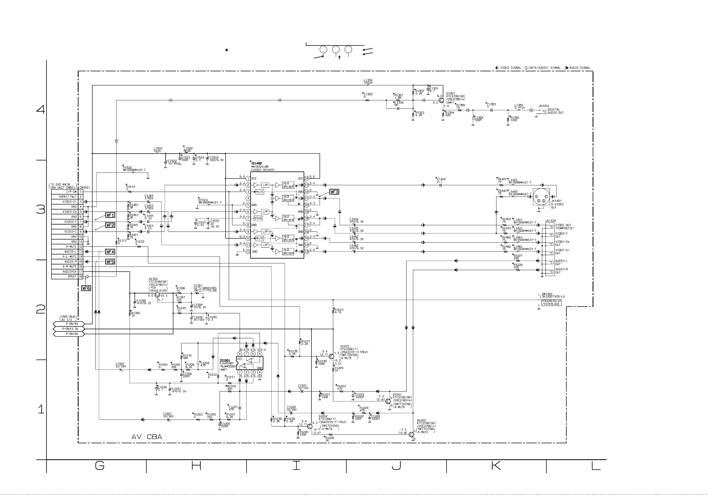
AV 2/3 Schematic Diagram
“ “ = SMD
Voltage indications for PLAY and STOP modes
on the Schematic Diagrams are as shown below:
1 2 3
5.0
THE SAME VOLTAGE FOR
BOTH PLAY & STOP MODES.
5.0
~
(2.5)
INDICATES THAT THE VOLTAGE
IS NOT CONSISTENT HERE.
PLAY MODE
STOP MODE
1-4-3
1-4-4
E5775SCAV2
Page 14
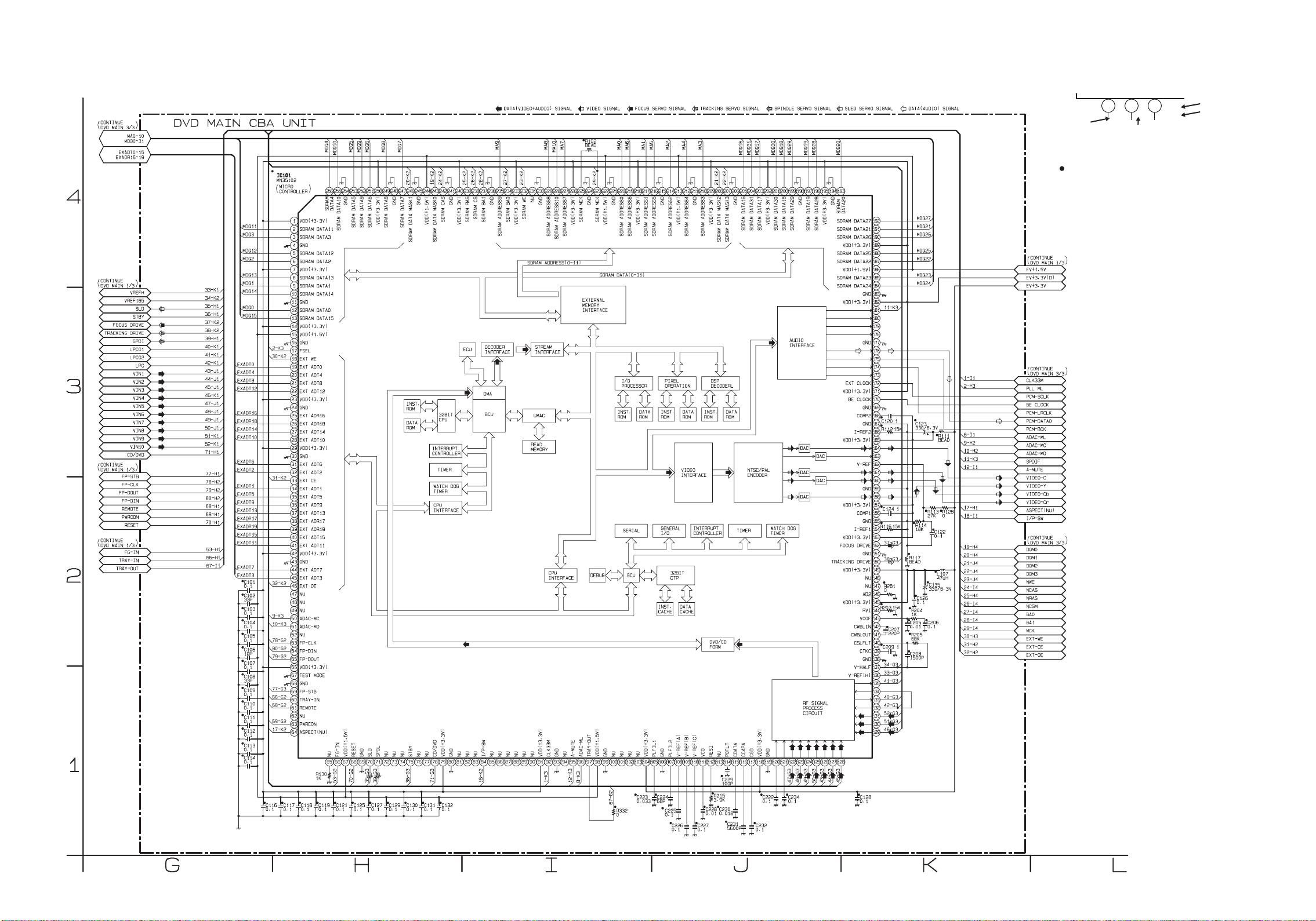
DVD Main 2/3 Schematic Diagram
Voltage indications for PLAY and STOP modes
on the Schematic Diagrams are as shown below:
1 2 3
5.0
(2.5)
~
5.0
THE SAME VOLTAGE FOR
BOTH PLAY & STOP MODES.
INDICATES THAT THE VOLTAGE
IS NOT CONSISTENT HERE.
PLAY MODE
STOP MODE
“ “ = SMD
1-4-5
1-4-6
E5775SCD2
Page 15

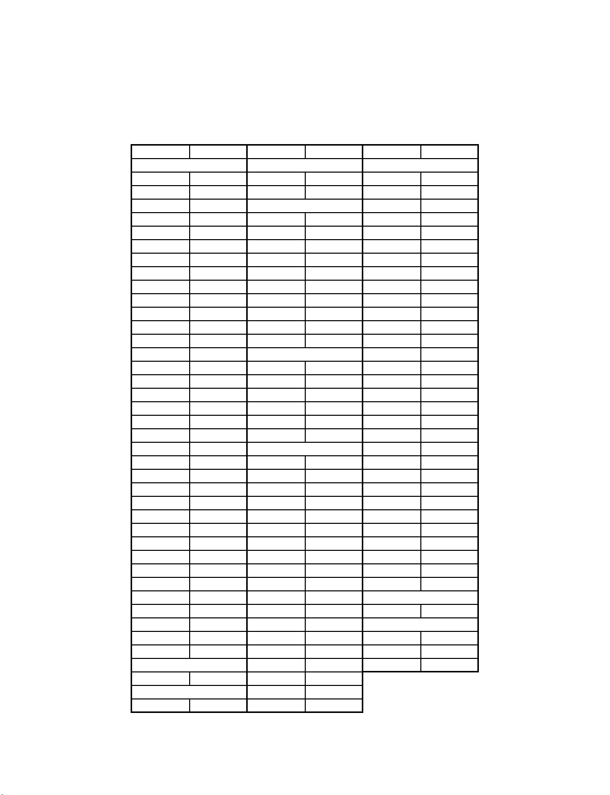
IC101 VOLTAGE CHART
PIN.NO PLAY STOP PIN.NO PLAY STOP PIN.NO PLAY STOP PIN.NO PLAY STOP
129 2.0 2.0 161 0.5 0.5 193 ~ ~ 225 1.9 1.9
130 2.2 2.2 162 1.4 1.4 194 0 0 226 3.3 3.3
131 2.3 2.3 163 ----- ----- 195 3.3 3.3 227 ~ ~
132 0.4 0.1 164 0.9 0.9 196 ~ ~ 228 ~ ~
133 1.2 0.4 165 3.3 3.3 197 ~ ~ 229 ~ ~
134 0.4 0.1 166 1.5 1.5 198 0 0 230 0 0
135 0.2 0.2 167 0 0 199 ~ ~ 231 ----- -----
136 2.3 2.3 168 2.1 2.1 200 ~ ~ 232 3.3 3.3
137 1.7 1.7 169 0 0 201 ~ ~ 233 3.3 3.3
138 0 0 170 0.8 0.8 202 3.3 3.3 234 1.6 1.6
139 1.7 1.7 171 3.3 3.3 203 ~ ~ 235 ~ ~
140 1.7 1.7 172 1.6 1.6 204 ~ ~ 236 0 0
141 1.7 1.7 173 ----- ----- 205 ~ ~ 237 1.7 1.7
142 1.7 1.7 174 1.8 1.8 206 0 0 238 3.0 3.0
143 0.5 0.5 175 1.7 1.7 207 2.4 3.5 239 3.3 3.3
144 1.6 1.6 176 1.4 0.1 208 2.4 2.1 240 3.3 3.3
145 3.3 3.3 177 0 0 209 3.3 3.3 241 0 0
146 0 0 178 ----- ----- 210 ~ ~ 242 3.2 3.2
147 ----- ----- 179 ----- ----- 211 0 0 243 2.4 2.1
148 ----- ----- 180 ----- ----- 212 ~ ~ 244 1.5 1.5
149 3.3 3.3 181 1.7 1.7 213 1.5 1.5 245 0 0
150 1.7 1.7 182 3.3 3.3 214 ~ ~ 246 2.4 2.1
151 0 0 183 0 0 215 0 0 247 ~ ~
152 1.7 1.7 184 ~ ~ 216 ~ ~ 248 0 0
153 3.3 3.3 185 ~ ~ 217 ~ ~ 249 ~ ~
154 1.4 1.4 186 1.5 1.5 218 3.3 3.3 250 3.3 3.3
155 0 0 187 ~ ~ 219 ~ ~ 251 ~ ~
156 2.2 2.2 188 ~ ~ 220 ~ ~ 252 ~ ~
157 3.3 3.3 189 3.3 3.3 221 0 0 253 ~ ~
158 0.7 0.7 190 ~ ~ 222 1.5 1.5 254 0 0
159 0 0 191 ~ ~ 223 1.9 1.9 255 ~ ~
160 0.5 0.5 192 ~ ~ 224 0 0 256 ~ ~
PIN.NO PLAY STOP PIN.NO PLAY STOP PIN.NO PLAY STOP PIN.NO PLAY STOP
1 3.33.3332.22.9650.10.1973.43.4
2 ~ ~ 34 ~ ~ 661.22.5981.61.6
3 ~ ~35~ ~671.61.6990 0
4 0 0 36 ~ ~ 68 3.4 3.4 100 ----- -----
5 ~ ~ 37 ~ ~ 69 0 0 101 ----- -----
6 ~ ~ 38 0.3 0.5 70 1.7 1.7 102 ----- -----
7 3.3 3.3 39 0.1 0.1 71 2.4 1.7 103 ----- -----
8 ~ ~ 40 ~ ~ 72 ----- ----- 104 3.3 3.3
9 ~ ~ 41 ~ ~ 73 ----- ----- 105 0.9 0.9
10 ~ ~ 42 3.3 3.3 74 ----- ----- 106 0 0
11 0 0 43 0 0 75 3.4 3.4 107 0.8 0.8
12 ~ ~ 44 ~ ~ 76 ----- ----- 108 1.6 1.6
13 ~ ~ 45 ~ ~ 77 ----- ----- 109 2.1 2.1
14 3.3 3.3 46 2.0 2.6 78 0.1 0.1 110 2.6 2.6
15 1.5 1.5 47 ----- ----- 79 3.3 3. 3 111 2.0 2.0
16 0 0 48 ----- ----- 80 0 0 112 0.7 0.9
17 3.4 3.4 49 ----- ----- 81 ----- ----- 113 ----- -----
18 3.4 3.4 50 3.4 3.4 82 ----- ----- 114 1.8 1.8
19 ~ ~ 51 3.4 3.4 83 ----- ----- 115 1.4 1.4
20 ~ ~ 52 ----- ----- 84 2.4 2.4 116 0.3 0.3
21 ~ ~ 53 3.4 3.4 85 ----- ----- 117 1.6 1.6
22 ~ ~ 54 3.4 3.4 86 ----- ----- 118 3.3 3.3
23 3.3 3.3 55 3.3 3.3 87 ----- ----- 119 0 0
24 0 0 56 3.3 3.3 88 ----- ----- 120 1.9 1.9
25 0.4 0.4 57 0 0 89 ----- ----- 121 1.9 1.9
26 0.9 0.6 58 0 0 90 ----- ----- 122 2.4 2.4
27 ~ ~ 59 3.3 3.3 91 3.3 3.3 123 2.4 2.4
28 ~ ~ 60 3.4 3.4 92 1.7 1.5 124 2.4 2.4
29 3.3 3.3 61 3.1 3.1 93 0 0 125 2.4 2.4
30 0 0 62 ----- ----- 94 ----- ----- 126 2.0 2.0
31 ~ ~ 63 3.4 3.4 95 3.4 0.1 127 2.0 2.0
32 ~ ~ 64 0.8 0.8 96 3.4 3.4 128 2.0 2.0
1-4-7 1-4-8
Page 16

DVD Main 3/3 Schematic Diagram
“ “ = SMD
Voltage indications for PLAY and STOP modes
on the Schematic Diagrams are as shown below:
1 2 3
5.0
THE SAME VOLTAGE FOR
BOTH PLAY & STOP MODES.
5.0
~
(2.5)
INDICATES THAT THE VOLTAGE
IS NOT CONSISTENT HERE.
PLAY MODE
STOP MODE
1-4-9
1-4-10
E5775SCD3
Page 17

WAVEFORMS
WF1 Pin 7 of CN1601
VIDEO-Y 0.2V 20µsec
WF2 Pin 9 of CN1601
WF5
Pin 15 of CN1601
AUDIO-R
WF6
Pin 18 of CN1601
1V 0.5msec
NOTE:
Input
CD: 1kHz PLAY
(WF4~WF6)
DVD: POWER ON (STOP) MODE
(WF1~WF3)
VIDEO-C 0.2V 20µsec
WF3 Pin 21 of IC1402
VIDEO-CVBS 0.5V 20µsec
WF4
Pin 13 of CN1601
SPDIF
1V 0.1µsec
AUDIO-L
1V 0.5msec
1-5-1
1-5-2
E5775WF
Page 18
VIDEO-Y
OUT
VIDEO-Cb
OUT
VIDEO-Cr
OUT
VIDEO
OUT
AUDIO-L
OUT
CN1001
AUDIO-R
OUT
DIGITAL
AUDIO OUT
S-VIDEO
OUT
2222
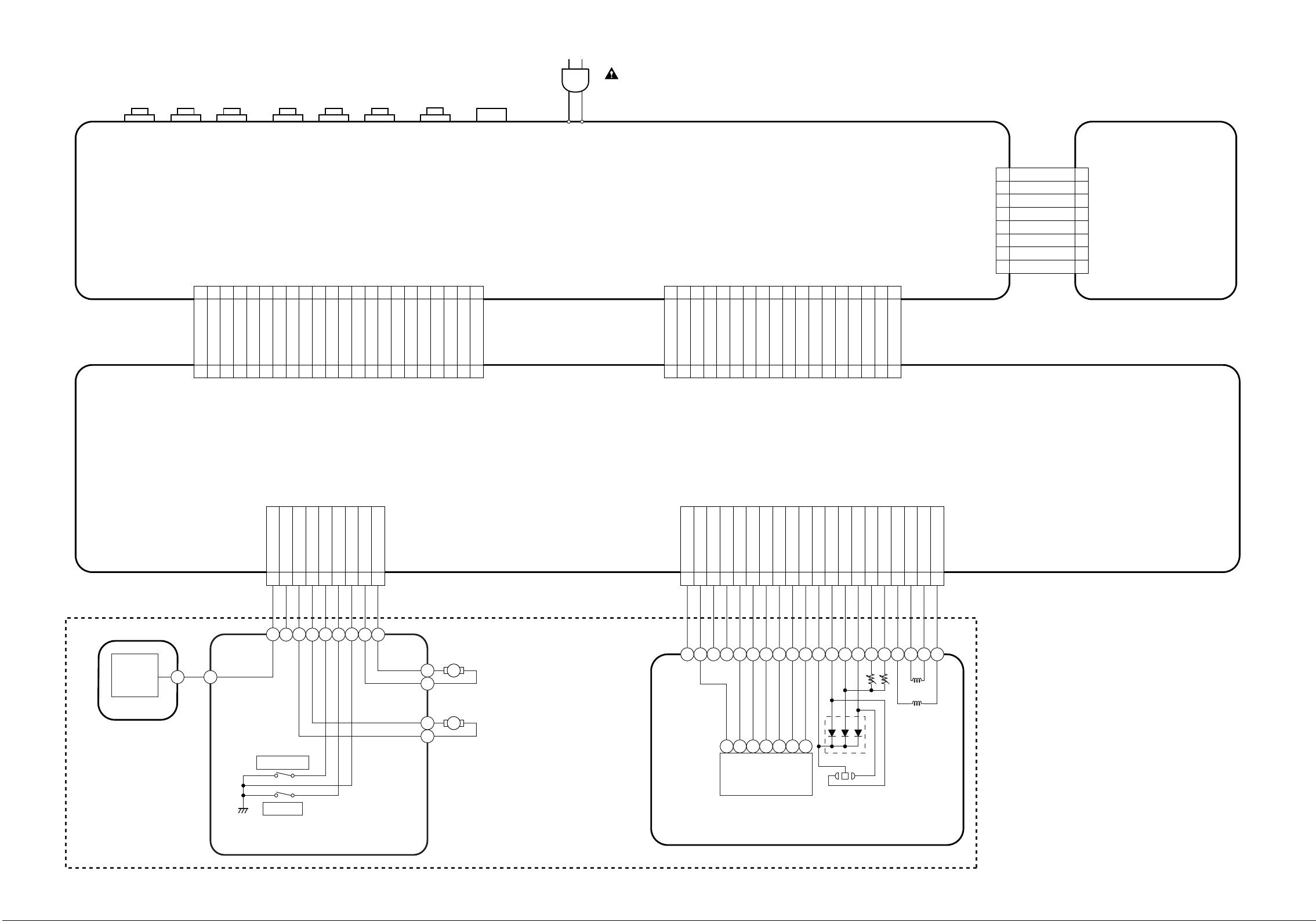
WIRING DIAGRAM
AV CBA
(BE57S0F01015)
AC CORD
CN1601
NOTE FOR WIRE CONNECTORS:
1. PREFIX SYMBOL "CN" MEANS CONNECTOR.
(CAN DISCONNECT AND RECONNECT.)
2. PREFIX SYMBOL "JP" MEANS WIRE-SOLDER
HOLES OF THE PCB.
(WIRE IS SOLDERED DIRECTLY.)
JP2001 JP2002
K2 1
1
KEY-2 2
2
NU 3
3
GND 4
4
KEY-4 5
5
KEY-3 6
6
KEY-1 7
7
K1 8
8
FUNCTION CBA
(BE57S0F01015)
FG
SENSOR
FG CBA
W1001
EV+1.5V 11
EV+1.5V 22
EV+3.3V 44
EV+3.3V 55
GND 66
GND 77
GND 88
GND 99
GND 1010
GND 1111
GND 1212
P-ON+5V 1313
EV+9V 1414
EV+9V 1515
FP-STB 1616
P-ON+3.3V 1717
FP-DIN 1818
EV+1.5V 33
CN401
PWRCON 1919
REMOTE
FP-DOUT 2020
FP-CLK 2121
W1601
AUDIO-L 1313
A-L-MUTE 1414
VIDEO-Cb 55
VIDEO-Y 77
VIDEO-Cr 33
I/P-SW 11
GND 44
ASPECT(NU) 22
GND 88
GND 66
CN601
GND 1111
VIDEO-C 99
A-MUTE 1212
GND 1010
AUDIO-R 1515
SPDIF 1818
A-R-MUTE 1616
AUDIO+5V 1717
DVD MAIN CBA UNIT
CN201CN301
FG-IN
123
SP(-)7SP(+)
P-ON+3.3V(D)
TRAY-OUT
TRAY-IN
GND
4
5
6
8 SL(-)
9 SL(+)
SLED
MOTOR
M
SPINDLE
MOTOR
M
GND
123456789
VREF
P-ON+5VFE
CBD
A
PD-MONI
GND(LD)
CD/DVD
101112131415161718
DVD-LD
CD-LD
GND(DVD-PD)
TS(+)
FS(-)
FS(+)
TS(-)
GND(CD-PD)
19
20
FS
TS
11 2 3 5 6 4 7
TRAY-OUT
DETECTOR
TRAY-IN
PICK UP UNIT
DRIVE CBA
DVD MECHA
1-6-1 1-6-2
E5775WI
Page 19
MECHANICAL PARTS LIST
PRODUCT SAFETY NOTE: Products marked with a
# have special characteristics important to safety.
Before replacing any of these components, read carefully the product safety notice in this service manual.
Don't degrade the safety of the product through
improper servicing.
NOTE: Parts that are not assigned part numbers
(---- --- ----- or blank) are not normally available.
To order parts call the TOLL FREE Philips Sales
Center number: 1 - 800 - 851 - 8885
(In Canada) 1 - 800 - 363 - PART.
1 - 800 - 535 - 3715 (Fax).
Ref. # Description ID No. Part No.
A1X FRONT ASSEMBLY 0VM204248
A2 TRAY PANEL 0VM415462
A13 FOOT(REAR) 0VM415007
A15 MAIN CHASSIS 0VM101219
A16 TOP COVER:SILVER 0VM101220
A17 REAR PANEL 0VM204250
A21 LABEL, SERIAL NO. ---------- -- -- --- -----
A22 LABEL, BAR CODE ---------- ---- --- --- --
A27 REGISTRATION CARD 0VMN03333
A28 LABEL, IMPORTANT ----------
1B1 DVD MECHA (THIN TYPE) N79F1GVM
2B3 HOLDER, MAIN PCB 0VM305832B
2L011 SCREW, C-TIGHT M3X5 BIND HEAD + GBCC3050
2L021 SCREW, S-TIGHT M3X8 BIND + CHROME GBMS3080
2L031 SCREW, C-TIGHT M3X6 BIND HEAD GBMC3060 ---- --- -----
2L041 SCREW, B-TIGHT M3X8 BIND HEAD + GBKB3080
2L071 SCREW, C-TIGHT M3X6 BIND HEAD GBMC3060 ---- --- -----
2L101 SCREW, C-TIGHT M3X6 BIND HEAD GBMC3060 ---- --- -----
2L105 P-TIGHT SCREW 3X8 BIND + GBMP3080
PACKING
S1 GIFT BOX CARTON 0VM306366
S2 STYROFOAM 0VM101231
S4 UNIT, BAG 0VM411683
S5 PAD 0VM414757
ACCESSORIES
X1 REMOTE CONTROL UNIT DVD NA820UD 4835 218 37353
X2 DRY BATTE RY R6P/2S or XB0M451T0001 4835 138 17012
X4 ACCESSORY BAG 0VM413280
X5 AV CORD TSCKA-Y/RW100 or WPZ0102TM015 4835 321 17148
X10 # OWNER'S MANUAL 0VMN03736 00IB 843 4E001
X12 SERVICE LOCATION MAP 0VMN03463
X13 # IMPORTANT SAFEGUARD 0VMN02376
X17 QUICK GUIDE 0VMN03780 8 239 300 27251
X33 STOP SHEET(MAGNAVOX) 0VMN03201
DRY BATTERY ES-GR6M-C XB0M571GLP01 4 835 138 17012
AV CORD RCA(M*2)TO RCA(M*2) WPZ0102LTE01 4835 321 17148
20030331 1-7-1 E5775CA
Page 20

ELECTRICAL PARTS LIST
PRODUCT SAFETY NOTE: Products marked with a
# have special characteristics important to safety.
Before replacing any of these components, read carefully the product safety notice in this service manual.
Don't degrade the safety of the product through
improper servicing.
To order parts call the TOLL FREE Philips Sales
Center number: 1 - 800 - 851 - 8885
(In Canada) 1 - 800 - 363 - PART.
1 - 800 - 535 - 3715 (Fax).
NOTES:
1. Parts that are not assigned part numbers
(---- --- ----- or blank) are not normally available.
2. “ ● ”=SMD
DVD MAIN CBA UNIT
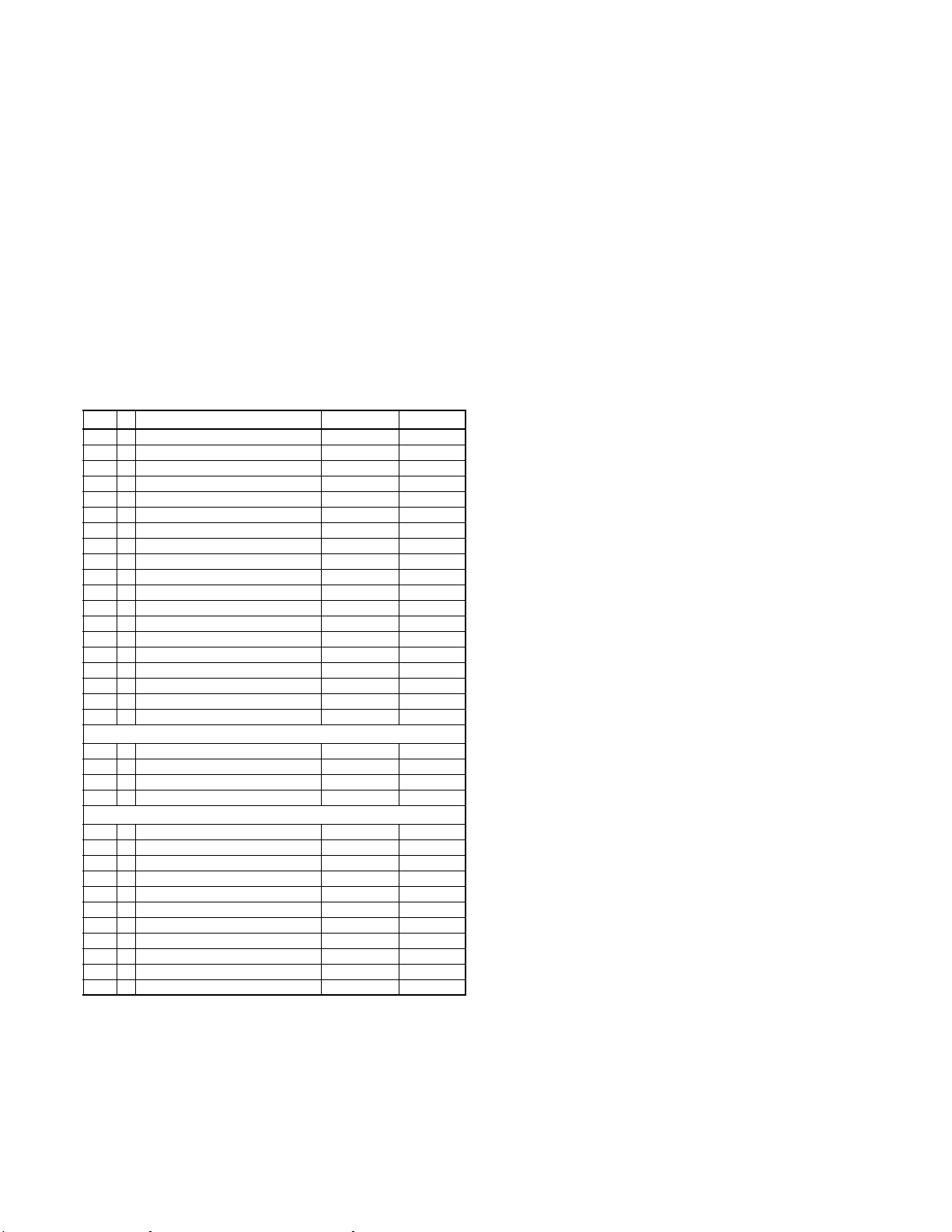
Ref. # Description ID No. Part No.
DVD MAIN CBA UNIT N79PBGUP
AV CBA ASSEMBLY
Ref. # Description ID No. Part No.
AV CBA ASSEMBLY
Consists of the followings:
AVC BA
FUNCTION CBA
MAIN CBA
Ref. # Description ID No. Part No.
AV C BA
Consists of the followings:
CAPACITORS
C1001 # METALLIZED FILM CAP. 0 .01µF/275V ±10% orCT2E103HJE05
# METALLIZED FILM CAP. 0.01µF/250V ±20% orCT2E103MS037
# METALLIZED FILM CAP. 0.01µF/250V ±10% CT2E10 3DC011 4835 122 47703
C1003 ELECTROLYTIC CAP. 2.2 µF/250V ±20% or CA2E2R2S6009 4835 124 47748
C1004 ELECTROLYTIC CAP. 82µF/200V ±20% or CA2D820S6014
C1005 CERAMIC CAP. 56pF/500V ±5% (CH) CCD2JJPCH560
C1006 # SAFETY CAP. 2200pF/250V or CCD2EMA0E222
C1007 ELECTROLYTIC CAP. 1000 µF/6.3V ±20% CE0KMASDL102 4835 124 47203
C1009 ELECTROLYTIC CAP. 2200 µF/6.3V ±20% CE0KMASTL222 4 835 121 47718
C1010 CERAMIC CAP.(AX) 560pF/50V ±5% (CH) CA1J561TU008 4835 122 47206
C1013 CERAMIC CAP.(AX) 3300pF/50V ±10% (B) CA1J332TU011
C1014 ELECTOLYTIC CAP. 1000µF/6.3V
C1017 CERAMIC CAP.(AX) 0.01µF/16V ±20% (Y) CCA1CMT0Y103 4835 122 47522
C1018 ELECTROLYTIC CAP. 100µF/6.3V ±20% CE0KMASDL101 4835 124 47165
●
C1021 CHIP CERAMI C CAP. 0.01µF/50V ±10 % (B) CHD1JK30B103 4835 122 87255
●
C1022 CHIP CERAMI C CAP. 0.01µF/50V ±10 % (B) CHD1JK30B103 4835 122 87255
C1029 CERAMIC CAP.(AX) 2200pF/16V ±10% (X) CCA1CKT0X222 4835 122 47727
ELECTROLYTIC CAP. 2.2µF/250V
°C)
±20%(105
ELECTROLYTIC CAP. 82µF/200V ±20% CA2D820NC002 4835 124 17017
# SAFETY CAP. 2200pF/250V or CCG2E MA0F222 4835 125 97034
# SAFETY CAP. 2200pF/125V CCG2BMA 0E222 4835 125 97033
±20%(105
°C)
0VSA13623
----------
----------
----------
CE2EMASTH2R2 4835 124 47748
CE0KMASDH102
Ref. # Description ID No. Part No.
C1034 ELECTROLYTIC CAP. 470µF/6.3V ±20% CE0KMASDL471 4835 124 4723 9
C1035 ELECTROLYTIC CAP. 470µF/16V ±20% CE1CMASDL471 4835 1 24 47286
●
C1036 CHIP CER AMIC CAP. 0.01µF/50 V ±10% (B) CHD1JK30B103 4835 122 87255
●
C1037 CHIP CER AMIC CAP. 0.1µF/50V +80/-20%
C1038 ELECTROLYTIC CAP. 470µF/6.3V ±20% CE0KMASDL471 4835 124 4723 9
●
C1039 CHIP CER AMIC CAP. 0.1µF/50V +80/-20%
C1047 FILM CAP. (P) 0.01µF/50V ±5% or CMA1JJS0010 3 4835 121 47461
C1048 ELECTROLYTIC CAP. 220µF/16V ±20% CE1CMASDL221 4835 1 24 47209
●
C1049 CHIP CER AMIC CAP. 0.1µF/50V +80/-20%
C1050 ELECTROLYTIC CAP. 220µF/6.3V ±20% CE0KMASDL221 4835 124 4716 8
C1201 ELECTROLYTIC CAP. 10µF/16V ±20% CE1CMASDL 100 4835 124 47268
C1202 ELECTROLYTIC CAP. 10µF/16V ±20% CE1CMASDL 100 4835 124 47268
●
C1205 CHIP CER AMIC CAP. 220pF/50V ± 5% (CH) CHD1JJ3CH2 21 4835 122 87137
●
C1206 CHIP CER AMIC CAP. 220pF/50V ± 5% (CH) CHD1JJ3CH2 21 4835 122 87137
●
C1207 CHIP CER AMIC CAP. 47pF/50V ± 5% (CH) CH D1JJ3CH470 4835 122 87148
●
C1208 CHIP CER AMIC CAP. 47pF/50V ± 5% (CH) CH D1JJ3CH470 4835 122 87148
C1221 ELECTROLYTIC CAP. 10µF/16V ±20% CE1CMASDL 100 4835 124 47268
C1222 ELECTROLYTIC CAP. 10µF/16V ±20% CE1CMASDL 100 4835 124 47268
●
C1223 CHIP CER AMIC CAP. 1000pF/50 V ±5% (CH) CHD1JJ3CH102
●
C1224 CHIP CER AMIC CAP. 1000pF/50 V ±5% (CH) CHD1JJ3CH102
●
C1245 CHIP CER AMIC CAP. 0.1µF/50V +80/-20%
●
C1246 CHIP CER AMIC CAP. 0.1µF/50V +80/-20%
C1247 ELECTROLYTIC CAP. 470µF/6.3V ±20% CE0KMASDL471 4835 124 4723 9
C1249 ELECTROLYTIC CAP. 47µF/16V ±20% CE1CMASDL 470 4835 124 47073
●
C1351 CHIP CER AMIC CAP. 0.1µF/25V ±10% (B) CHD1E K30B104 4835 122 8721 3
●
C1353 CHIP CER AMIC CAP. 1µF/10V ± 10% (B) CHD 1AK30B105 483 5 122 87639
●
C1354 CHIP CER AMIC CAP. 100pF/50V ± 5% (CH) CHD1JJ3CH1 01 4835 122 87193
●
C1355 CHIP RES.(1608) 1/10W 0 Ω RRXAZR5Z0000 4835 1 11 37215
●
C1358 CHIP CERAMIC CAP. 9pF/50V ±0.5% (CH) CHD1JD3CH9R0
C1394 ELECTROLYTIC CAP. 47µF/6.3V ±20% CE0KMASDL470 4835 124 47265
C1395 ELECTROLYTIC CAP. 470µF/6.3V ±20% CE0KMASDL471 4835 124 4723 9
C1402 ELECTROLYTIC CAP. 470µF/6.3V ±20% CE0KMASDL471 4835 124 4723 9
●
C1421 CHIP CER AMIC CAP. 0.01µF/50 V ±10% (B) CHD1JK30B103 4835 122 87255
●
C1422 CHIP CER AMIC CAP. 0.1µF/25V ±10% (B) CHD1E K30B104 4835 122 8721 3
●
C1441 CHIP CER AMIC CAP. 0.33µF/10 V ±10% (B) CHD1AK30B334
C1442 ELECTROLYTIC CAP. 470µF/6.3V ±20% CE0KMASDL471 4835 124 4723 9
C1461 ELECTROLYTIC CAP. 1µF/50V ±20% CE1JMASDL010 4835 124 47014
C1462 ELECTROLYTIC CAP. 470µF/6.3V ±20% CE0KMASDL471 4835 124 4723 9
C1481 ELECTROLYTIC CAP. 1µF/50V ±20% CE1JMASDL010 4835 124 47014
C1482 ELECTROLYTIC CAP. 470µF/6.3V ±20% CE0KMASDL471 4835 124 4723 9
●
C1521 CHIP CER AMIC CAP. 100pF/50V ± 5% (CH) CHD1JJ3CH1 01 4835 122 87193
C1522 ELECTROLYTIC CAP. 10µF/16V ±20% CE1CMASDL 100 4835 124 47268
●
C1523 CHIP CER AMIC CAP. 0.1µF/50V +80/-20%
C1524 ELECTROLYTIC CAP. 100µF/6.3V ±20% CE0KMASDL101 4835 124 4716 5
●
C1531 CHIP CER AMIC CAP. 0.01µF/50 V ±10% (B) CHD1JK30B103 4835 122 87255
C1532 ELECTROLYTIC CAP. 22µF/6.3V ±20% CE0KMASDL220 4835 124 47238
C2001 ELECTROLYTIC CAP. 22µF/50V ±20% CE1JMASDL 220 4835 124 47051
C2002 ELECTROLYTIC CAP. 22µF/50V ±20% CE1JMASDL 220 4835 124 47051
●
C2004 CHIP CER AMIC CAP. 0.1µF/50V +80/-20%
●
C2011 CHIP CER AMIC CAP. 0.1µF/50V +80/-20%
C2012 ELECTROLYTIC CAP. 100µF/6.3V ±20% CE0KMASDL101 4835 124 4716 5
●
C2013 CHIP CER AMIC CAP. 1000pF/50 V ±5% (CH) CHD1JJ3CH102
(F)
(F)
FILM CAP.(P) 0.01µF/50V ±5% CA1J103MS029 4835 121 47461
(F)
(F)
(F)
(F)
(F)
(F)
CHD1JZ30F104 4835 122 8764 5
CHD1JZ30F104 4835 122 8764 5
CHD1JZ30F104 4835 122 8764 5
CHD1JZ30F104 4835 122 8764 5
CHD1JZ30F104 4835 122 8764 5
CHD1JZ30F104 4835 122 8764 5
CHD1JZ30F104 4835 122 8764 5
CHD1JZ30F104 4835 122 8764 5
CONNECTORS
CN1001 FMN CONNECTOR, TOP 22P 22FMN-BTK JCFNG22JG001 ---- --- -----
CN1601 FMN CONNECTOR, TOP 18P 18FMN-BTK orJCFNG18JG001
FFC/FPC CONNECTOR 18P 00 6232 018
000 800
JC62G18TM009
20030331 1-8-1 E5775EL
Page 21

Ref. # Description ID No. Part No.
DIODES
D1001 RECTIFIER DIODE 1N4005 NDQZ001 N4005 4835 130 37047
D1002 RECTIFIER DIODE 1N4005 NDQZ001 N4005 4835 130 37047
D1003 RECTIFIER DIODE BA157 or NDQZ000BA157 4835 130 37052
FAST RECOVERY DIODE ERA18-04 QDPZ0ERA1804 4835 130 37641
D1004 RECTIFIER DIODE 1N4005 NDQZ001 N4005 4835 130 37047
D1005 RECTIFIER DIODE 1N4005 NDQZ001 N4005 4835 130 37047
D1006 SCHOTTKY BARRIER DIODE SB140 or N DQZ000SB140 4 835 130 37894
SCHOTTKY BARRIER DIODE ER A81-004 QDPZERA81004 4835 130 37211
D1008 SCHOTTKY BARRIER DIODE SB140 or N DQZ000SB140 4 835 130 37894
SCHOTTKY BARRIER DIODE ER A81-004 QDPZERA81004 4835 130 37211
D1011 RECTIFIER DIODE BA157 or NDQZ000BA157 4835 130 37052
FAST RECOVERY DIODE ERA18-04 QDPZ0ERA1804 4835 130 37641
D1012 SWITCHING DIODE 1N4148M or NDTZ01N4148M 4835 130 37048
SWITCHING DIODE 1S S133(T-77) QDTZ001SS 133 4835 130 37235
D1015 ZENER DIODE DZ-6.8BSBT265 or NDTB0 DZ6R8BS 4835 130 38027
ZENER DIODE MTZJT-776.8B QDTB0MTZJ6R8 4835 130 37881
D1016 RECTIFIER DIODE BA157 or NDQZ000BA157 4835 130 37052
FAST RECOVERY DIODE ERA18-04 QDPZ0ERA1804 4835 130 37641
D1017 ZENER DIODE DZ-22BSBT265 or NDTB00DZ22BS 4835 130 38056
ZENER DIODE MTZJT-7722B QDTB00MTZJ22 4 835 130 38017
D1018 SWITCHING DIODE 1N4148M or NDTZ01N4148M 4835 130 37048
SWITCHING DIODE 1S S133(T-77) QDTZ001SS 133 4835 130 37235
D1024 SWITCHING DIODE 1N4148M or NDTZ01N4148M 4835 130 37048
SWITCHING DIODE 1S S133(T-77) QDTZ001SS 133 4835 130 37235
D1030 RECTIFIER DIODE FR202 or NDQZ000FR202 4835 130 38058
FAST RECOVERY DIODE ERB32-01L3 QDQZ0ERB3201 4835 130 37149
D1046 ZENER DIODE DZ-5.6BSCT265 or NDTC0DZ5R6BS 4 835 130 38026
ZENER DIODE MTZJT-775.6C QDTC0MTZJ5R6 4835 130 37329
D1047 ZENER DIODE DZ-5.1BSBT265 or NDTB0 DZ5R1BS 4835 130 38025
ZENER DIODE MTZJT-775.1B QDTB0MTZJ5R1 4835 130 37964
D1048 ZENER DIODE DZ-15BSAT265 or NDTA00DZ15BS 4835 130 38029
ZENER DIODE MTZJT-7715A QDTA00MTZJ15 4835 130 38046
D1051 ZENER DIODE DZ-6.2BSBT265 or NDTB0 DZ6R2BS 4835 130 38039
ZENER DIODE MTZJT-776.2B QDTB0MTZJ6R2 4835 130 37593
D1053 PCB JUMPER D0.6-P10.0 JW10.0T ---- --- -----
D1054 PCB JUMPER D0.6-P10.0 JW10.0T ---- --- -----
D1055 SWITCHING DIODE 1N4148M or NDTZ01N4148M 4835 130 37048
SWITCHING DIODE 1S S133(T-77) QDTZ001SS 133 4835 130 37235
D1058 SCHOTTKY BARRIER DIODE SB140 or N DQZ000SB140 4 835 130 37894
SCHOTTKY BARRIER DIODE ER A81-004 QDPZERA81004 4835 130 37211
D1301 ZENER DIODE DZ-5.6BSBT265 or NDTB0 DZ5R6BS 4835 130 38026
ZENER DIODE MTZJT-775.6B QDTB0MTZJ5R6 4835 130 37329
D2005 SWITCHING DIODE 1N4148M or NDTZ01N4148M 4835 130 37048
SWITCHING DIODE 1S S133(T-77) QDTZ001SS 133 4835 130 37235
D2006 SWITCHING DIODE 1N4148M or NDTZ01N4148M 4835 130 37048
SWITCHING DIODE 1S S133(T-77) QDTZ001SS 133 4835 130 37235
D2007 SWITCHING DIODE 1N4148M or NDTZ01N4148M 4835 130 37048
SWITCHING DIODE 1S S133(T-77) QDTZ001SS 133 4835 130 37235
D2008 SWITCHING DIODE 1N4148M or NDTZ01N4148M 4835 130 37048
SWITCHING DIODE 1S S133(T-77) QDTZ001SS 133 4835 130 37235
D2010 PCB JUMPER D0.6-P5.0 JW5.0T
ICS
IC1001 # IC, ERROR VOLTAGE DET LTV-817B-F or NPEB0LTV817F 4 835 130 37977
# IC, ERROR VOLTAGE DET LTV-817C-F NPEC0LTV817F 4835 130 37977
IC1002 IC, +1.5V REGULATOR PQ070XF01SZ QSZBA0SSH026 4835 209 47612
IC1006 IC, SHUNT REGULATOR KIA431-AT NSZLA0TJ Y001 4835 209 88194
IC1201 IC, AMP KIA4558P or NSZBA0SJY004
IC, AMP NJM4558D QSZBA0SJR006 4835 209 47544
IC1402 IC, VIDEO DRIVER MM 1622XJBE QSZBA0TMM085
IC2001 IC, FRONT PANEL CONTROL PT6313-S-TP NSZBA0TG2006
COILS
L1001 # L INE FILTE R 20MH SA-00911 LLBG00 ZSA003
L1007 CHOKE COIL 22µH-K LLBD00PKV006 4835 157 58024
L1008 CHOKE COIL 22µH-K LLBD00PKV006 4835 157 58024
L1009 CHOKE COIL 22µH-K LLBD00PKV006 4835 157 58024
Ref. # Description ID No. Part No.
L1011 BEAD CORE B16 RH 3.5X3X1.3 XL03003X M002
L1043 BEAD CORE B16 RH 4X3X2 X L03003XM001 ---- --- -----
L1060 BEAD CORE B16 RH 3.5X3X1.3 XL03003X M002
L1350 INDUCTOR 100µH-K-26T LLAXKATTU101 4835 157 57369
L1351 INDUCTOR 0.47µH-K-26T LLAXKATTUR47 4835 157 5801 8
●
L1401 CHIP INDUCTOR BK1608HM121-T LLBC003TU051
●
L1421 CHIP INDUCTOR BK1608HM121-T LLBC003TU051
●
L1441 CHIP INDUCTOR BK1608HM121-T LLBC003TU051
●
L1442 CHIP INDUCTOR BK1608HM121-T LLBC003TU051
●
L1461 CHIP INDUCTOR BK1608HM121-T LLBC003TU051
●
L1481 CHIP INDUCTOR BK1608HM121-T LLBC003TU051
L1521 CHOKE COIL 22µH-K LLBD00PKV006 4835 157 5802 4
●
L1522 CHIP BEAD MMZ1608R102CT XL06001TE002
L2001 PCB JUMPER D0.6-P5.0 JW5.0T
L2002 INDUCTOR 100µH-K-26T LLAXKATTU101 4835 157 57369
L2003 PCB JUMPER D0.6-P5.0 JW5.0T
TRANSISTORS
Q1001 SWITCHIN G 2SK3374 QFWZ02SK3374
Q1002 SWITCH ING P-ON+9V KTA1267(Y) "PNP" NQSY0KTA1267 4835 130 47913
Q1003 SWI TCHING CONTROL KTC3199(GR)
"NPN" or
NQS10KTC3199 4835 130 47914
SWITCHING CONTROL 2SC 2785(H) "NPN" QQSH02SC2785 4835 1 30 47722
Q1004 SWITCHIN G P-ON+5V KTC3198(Y) "NPN" NQSY0KTC31 98 4835 130 47946
Q1005 SWITCH ING P-ON-ON KTC3198(Y) "NPN" NQSY0KTC319 8 4835 130 47946
Q1006 SHUNT REGULATOR KRA110M " PNP" or NQSZ0KRA110M 4835 130 48158
SHUNT REGULATOR BN1L3Z(P) QQSP00BN1L3Z
Q1011 SWITCHIN G P-ON+3.3V 2SC2120-Y(TPE2)
"NPN"
QQSY02SC2120 4835 130 48047
Q1015 SWITCH ING P-ON-ON KRA110M "PNP" or NQS Z0KRA110M 4835 130 4815 8
SWITCHING P-ON-ON BN1L3Z(P) QQSP00BN1L3Z
Q1016 SWITCH ING P-ON-ON KTC3199(GR) "NPN" orNQS10KTC3199 4835 130 47914
SWITCHING P-ON-ON 2 SC2785(H) "NPN" QQSH02SC2785 4835 130 47722
Q1201 SWITCH ING A-MUTE KTC3199(GR) "NPN" orNQS10KTC3199 4835 130 47914
SWITCHING A-MUTE 2SC2785(H) "NPN" QQSH02SC2785 4835 130 47722
Q1202 SWITCH ING A-MUTE KTC3199(GR) "NPN" orNQS10KTC3199 4835 130 47914
SWITCHING A-MUTE 2SC2785(H) "NPN" QQSH02SC2785 4835 130 47722
Q1203 SWITCHIN G A-MUTE KTA1266(Y) "PNP" or NQSY0KTA1266 4835 130 47422
SWITCHING A-MUTE 2SA1015-Y(TPE2)
"PNP"
QQSY02SA1015
Q1204 SWITCHIN G A-MUTE KTA1266(Y) "PNP" or NQSY0KTA1266 4835 130 47422
SWITCHING A-MUTE 2SA1015-Y(TPE2)
"PNP"
QQSY02SA1015
Q1351 AMP KT C3199(GR) "NPN" or NQS10KTC3199 4835 130 4791 4
AMP 2SC2785(H) "NPN" QQSH02SC2785 4835 130 47722
Q1352 +5V RE GURATOR KTC3199(GR ) "NPN" or NQ S10KTC3199 483 5 130 47914
+5V REGURATOR 2SC2785(H) "NPN" QQSH02SC278 5 4835 1 30 47722
RESISTORS
●
R1002 CHIP RES.(1608) 1/10W 390 Ω ±5% RRXAJR5Z0391 483 5 111 37253
R1004 METAL OXIDE FILM RES. 2W 82k Ω ±5% or RN02823ZU001
R1005 CARBON RES. 1/4W 2.7M Ω ±5% RCX4JATZ0275 4835 110 5737 2
R1006 CARBON RES. 1/4W 2.7M Ω ±5% RCX4JATZ0275 4835 110 5737 2
R1008 CARBON RES. 1/4W 1k Ω ±5% RCX4JATZ0102 4835 110 57025
R1010 CARBON RES. 1/6W 15k Ω ±5% or RCX6JATZ0153 483 5 111 37307
R1011 METAL OXIDE FILM RES. 1W 1.2 Ω ±5% or RN011R2ZU001 4835 116 67022
R1013 CARBON RES. 1/4W 560 Ω ±5% RCX4JATZ0561 4835 110 57052
R1015 CARBON RES. 1/4W 560 Ω ±5% RCX4JATZ0561 4835 110 57052
R1016 CARBON RES. 1/6W 22k Ω ±5% or RCX6JATZ0223 483 5 111 37177
●
R1019 CHIP RES.(1608) 1/16W 820 Ω or RRXGFR5Z0821
●
R1020 CHIP RES.(1608) 1/10W 2.7k Ω ±5% RRXAJR5Z0272 4835 111 37243
●
R1021 CHIP RES.(1608) 1/10W 5.6k Ω ±5% RRXAJR5Z0562 4835 111 37376
●
R1022 CHIP RES.(1608) 1/10W 820 Ω ±5% RRXAJR5Z0821 483 5 111 37466
METAL OXIDE FILM RES. 2W 82k Ω ±5% RN02823KE009
CARBON RES. 1/4W 15k Ω ±5% RCX4JATZ0153 4835 110 57032
METAL OXIDE FILM RES. 1W 1.2 Ω ±5% RN011R2KE009 4835 116 6702 2
CARBON RES. 1/4W 22k Ω ±5% RCX4JATZ0223 4835 110 57038
CHIP RES. 1/10W 820 Ω RRXAFR5Z8200
20030331 1-8-2 E5775EL
Page 22

Ref. # Description ID No. Part No.
●
R1023 CHIP RES.(16 08) 1/16W 2.4k Ω or RRXGFR5Z0242
CHIP RES.(1608) 1/10W 2.4k Ω ±1% RRXAFR5Z2401
●
R1025 CHIP RES.(16 08) 1/10W 10k Ω ±5% RRXAJR5Z0103 4 835 111 37216
R1029 CARBON RES. 1/6W 470k Ω ±5% or RCX6JATZ0474 4835 110 57225
CARBON RES. 1/4W 470k Ω ±5% RCX4 JATZ0474 4835 110 57225
R1032 CARBON RES. 1/6W 3.3k Ω ±5% or RCX6JATZ0332 4835 111 37185
CARBON RES. 1/4W 3.3k Ω ±5% RCX4JATZ0332 4835 110 57046
R1035 CARBON RES. 1/4W 1k Ω ±5% RCX4JATZ0102 4835 110 57025
R1043 METAL OXIDE FILM RES. 1W 2.7 Ω ±5% or RN012R 7ZU001 4835 116 57346
METAL OXIDE FILM RES. 1W 2.7 Ω ±5% RN012R7K E009 4835 116 57346
●
R1044 CHIP RES.(16 08) 1/10W 100k Ω ±5% RRXA JR5Z0104 4835 111 37 434
●
R1059 CHIP RES.(16 08) 1/10W 10k Ω ±5% RRXAJR5Z0103 4 835 111 37216
●
R1067 CHIP RES.(1608) 1/10W 1k Ω ±5% RRXAJR5Z0102 4 835 111 17068
R1068 CARBON RES. 1/4W 1k Ω ±5% RCX4JATZ0102 4835 110 57025
R1069 CARBON RES. 1/6W 470 Ω ±5% or RCX6JATZ0471 4835 111 37193
CARBON RES. 1/4W 470 Ω ±5% RCX4JATZ0471 4835 110 57167
R1073 METAL OXIDE FILM RES. 2W 22 Ω ±5% or R N02220ZU001 4835 116 57368
METAL OXIDE FILM RES. 2W 22 Ω ±5% RN02220KE009
R1074 RECTIFIER DIODE 1N4005 NDQZ001 N4005 4835 130 37047
●
R1075 CHIP RES.(16 08) 1/10W 2.7k Ω ±5% RRXAJR5Z0272 4835 111 37243
●
R1076 CHIP RES.(16 08) 1/10W 10k Ω ±5% RRXAJR5Z0103 4 835 111 37216
●
R1078 CHIP RES.(1608) 1/10W 470 Ω ±5% RRXAJR5Z0471 4835 111 37259
R1079 CARBON RES. 1/4W 0.47 Ω ±5% RCX4JATZ0R47 4835 110 57343
●
R1080 CHIP RES.(16 08) 1/10W 22k Ω ±5% RRXAJR5Z0223 4 835 111 37441
●
R1081 CHIP REG. 1/16W 100 Ω or RRXGFR5Z0101
CHIP RES. 1/10W 100 Ω RRXAFR5Z1000
●
R1082 CHIP RES.(16 08) 1/10W 10k Ω ±5% RRXAJR5Z0103 4 835 111 37216
R1083 CARBON RES. 1/4W 0.47 Ω ±5% RCX4JATZ0R47 4835 110 57343
R1084 CARBON RES. 1/6W 220k Ω ±5% or RCX6JATZ0224 4835 110 57208
CARBON RES. 1/4W 220k Ω ±5% RCX4 JATZ0224 4835 110 57208
●
R1085 CHIP RES.(16 08) 1/10W 6.8k Ω ±5% RRXAJR5Z0682 4835 111 37272
●
R1086 CHIP RES.(1608) 1/10W 0 Ω RRXAZR5Z0000 4835 111 37215
●
R1091 CHIP RES.(1608) 1/10W 0 Ω RRXAZR5Z0000 4835 111 37215
●
R1203 CHIP RES.(1608) 1/10W 0 Ω RRXAZR5Z0000 4835 111 37215
●
R1204 CHIP RES.(1608) 1/10W 0 Ω RRXAZR5Z0000 4835 111 37215
●
R1205 CHIP RES.(16 08) 1/16W 20k Ω or RRXGFR5Z0203
CHIP RES.(1608) 1/10W 20k Ω ±1% RRXAFR5Z2002
●
R1206 CHIP RES.(16 08) 1/16W 20k Ω or RRXGFR5Z0203
CHIP RES.(1608) 1/10W 20k Ω ±1% RRXAFR5Z2002
●
R1207 CHIP RES.(16 08) 1/10W 8.2k Ω ±5% RRXAJR5Z0822 4835 111 37448
●
R1208 CHIP RES.(16 08) 1/10W 8.2k Ω ±5% RRXAJR5Z0822 4835 111 37448
●
R1209 CHIP RES. 1 /16W 30k Ω or RRXGFR5Z0303
CHIP RES.(1608) 1/10W 30k Ω ±1% RRXAFR5Z3002
●
R1210 CHIP RES. 1 /16W 30k Ω or RRXGFR5Z0303
CHIP RES.(1608) 1/10W 30k Ω ±1% RRXAFR5Z3002
●
R1211 CHIP RES.(1608) 1/10W 0 Ω RRXAZR5Z0000 4835 111 37215
●
R1212 CHIP RES.(1608) 1/10W 0 Ω RRXAZR5Z0000 4835 111 37215
●
R1221 CHIP RES.(16 08) 1/10W 100k Ω ±5% RRXA JR5Z0104 4835 111 37 434
●
R1222 CHIP RES.(16 08) 1/10W 100k Ω ±5% RRXA JR5Z0104 4835 111 37 434
●
R1223 CHIP RES.(1608) 1/10W 470 Ω ±5% RRXAJR5Z0471 4835 111 37259
●
R1224 CHIP RES.(1608) 1/10W 470 Ω ±5% RRXAJR5Z0471 4835 111 37259
●
R1225 CHIP RES.(1608) 1/10W 1k Ω ±5% RRXAJR5Z0102 4 835 111 17068
●
R1226 CHIP RES.(1608) 1/10W 1k Ω ±5% RRXAJR5Z0102 4 835 111 17068
●
R1227 CHIP RES.(1608) 1/10W 220 Ω ±5% RRXAJR5Z0221 4835 111 37371
●
R1228 CHIP RES.(1608) 1/10W 220 Ω ±5% RRXAJR5Z0221 4835 111 37371
●
R1233 CHIP RES.(1608) 1/10W 0 Ω RRXAZR5Z0000 4835 111 37215
●
R1235 CHIP RES.(16 08) 1/10W 2.2k Ω ±5% RRXAJR5Z0222 4835 111 37234
●
R1236 CHIP RES.(16 08) 1/10W 2.2k Ω ±5% RRXAJR5Z0222 4835 111 37234
●
R1237 CHIP RES.(16 08) 1/10W 2.2k Ω ±5% RRXAJR5Z0222 4835 111 37234
●
R1238 CHIP RES.(16 08) 1/10W 2.2k Ω ±5% RRXAJR5Z0222 4835 111 37234
●
R1239 CHIP RES.(16 08) 1/10W 100k Ω ±5% RRXA JR5Z0104 4835 111 37 434
●
R1240 CHIP RES.(16 08) 1/10W 100k Ω ±5% RRXA JR5Z0104 4835 111 37 434
●
R1245 CHIP RES.(1608) 1/10W 10 Ω ±5% RRXAJR5Z0100 4835 111 17 393
●
R1351 CHIP RES.(16 08) 1/10W 1.8k Ω ±5% RRXAJR5Z0182 4835 111 37231
●
R1352 CHIP RES.(16 08) 1/10W 2.2k Ω ±5% RRXAJR5Z0222 4835 111 37234
●
R1353 CHIP RES.(16 08) 1/10W 2.2k Ω ±5% RRXAJR5Z0222 4835 111 37234
●
R1354 CHIP RES.(1608) 1/10W 220 Ω ±5% RRXAJR5Z0221 4835 111 37371
Ref. # Description ID No. Part No.
●
R1355 CHIP RES.(1608) 1/10W 75 Ω ±5% RRXAJR5Z0750 4835 111 17131
●
R1356 CHIP RES.(1608) 1/10W 100k Ω ±5% RRXAJR5Z0104 4835 111 37434
●
R1371 CHIP RES.(1608) 1/10W 0 Ω RRXAZR5Z0000 4835 1 11 37215
●
R1392 CHIP RES.(1608) 1/10W 1k Ω ±5% RRXA JR5Z0102 4835 111 1706 8
●
R1396 CHIP RES.(1608) 1/10W 1k Ω ±5% RRXA JR5Z0102 4835 111 1706 8
●
R1397 CHIP RES.(1608) 1/10W 100 Ω ±5% RRXAJR5Z0101 483 5 111 37432
●
R1402 CHIP RES.(1608) 1/10W 75 Ω ±5% RRXAJR5Z0750 4835 111 17131
●
R1421 CHIP RES. 1/16W 75 Ω or RRXGFR5Z0750
CHIP RES.(1608) 1/10W 75 Ω ±1% RRXAFR5Z75R0
●
R1422 CHIP RES.(1608) 1/10W 75 Ω ±5% RRXAJR5Z0750 4835 111 17131
●
R1441 CHIP RES. 1/16W 75 Ω or RRXGFR5Z0750
CHIP RES.(1608) 1/10W 75 Ω ±1% RRXAFR5Z75R0
●
R1442 CHIP RES.(1608) 1/10W 75 Ω ±5% RRXAJR5Z0750 4835 111 17131
●
R1443 CHIP RES.(1608) 1/10W 75 Ω ±5% RRXAJR5Z0750 4835 111 17131
●
R1461 CHIP RES(1608) 1/16W 36 Ω or RRXGFR5Z0360
CHIP RES.(1608) 1/10W 36 Ω ±1% RRXAFR5Z36R0
●
R1462 CHIP RES.(1608) 1/10W 75 Ω ±5% RRXAJR5Z0750 4835 111 17131
●
R1481 CHIP RES(1608) 1/16W 36 Ω or RRXGFR5Z0360
CHIP RES.(1608) 1/10W 36 Ω ±1% RRXAFR5Z36R0
●
R1482 CHIP RES.(1608) 1/10W 75 Ω ±5% RRXAJR5Z0750 4835 111 17131
●
R1522 CHIP INDUCTOR BK1608HM121-T LLBC003TU051
●
R1523 CHIP INDUCTOR BK1608HM121-T LLBC003TU051
●
R1524 CHIP INDUCTOR BK1608HM121-T LLBC003TU051
●
R1613 CHIP RES.(1608) 1/10W 4.7k Ω ±5% RRXAJR5Z0472 4835 111 37426
●
R1614 CHIP RES.(1608) 1/10W 0 Ω RRXAZR5Z0000 4835 1 11 37215
●
R2015 CHIP RES.(1608) 1/10W 100k Ω ±5% RRXAJR5Z0104 4835 111 37434
●
R2016 CHIP RES.(1608) 1/10W 10k Ω ±5% RRX AJR5Z0103 4835 111 3721 6
●
R2017 CHIP RES.(1608) 1/10W 10k Ω ±5% RRX AJR5Z0103 4835 111 3721 6
●
R2025 CHIP RES.(1608) 1/10W 0 RRXAZR5Z0000 4835 111 37215
●
R2026 CHIP RES.(1608) 1/10W 6.8k Ω ±5% RRXAJR5Z0682 4835 111 37272
●
R2028 CHIP RES.(1608) 1/10W 10k Ω ±5% RRX AJR5Z0103 4835 111 3721 6
●
R2031 CHIP RES.(1608) 1/10W 22k Ω ±5% RRX AJR5Z0223 4835 111 3744 1
●
R2033 CHIP RES.(1608) 1/10W 0 Ω RRXAZR5Z0000 4835 1 11 37215
●
R2041 CHIP RES.(1608) 1/10W 0 Ω RRXAZR5Z0000 4835 1 11 37215
●
R2042 CHIP RES.(1608) 1/10W 10k Ω ±5% RRX AJR5Z0103 4835 111 3721 6
●
R2048 CHIP RES.(1608) 1/10W 10k Ω ±5% RRX AJR5Z0103 4835 111 3721 6
●
R2049 CHIP RES.(1608) 1/10W 10k Ω ±5% RRX AJR5Z0103 4835 111 3721 6
R2053 CARBON RES. 1/6W 10 Ω ±5% or RCX6JATZ0100 4835 111 37159
CARBON RES. 1/4W 10 Ω ±5% RCX4JATZ0100 4835 110 57002
●
R2054 CHIP RES.(1608) 1/10W 1k Ω ±5% RRXA JR5Z0102 4835 111 1706 8
●
R2055 CHIP RES.(1608) 1/10W 1k Ω ±5% RRXA JR5Z0102 4835 111 1706 8
●
R2056 CHIP RES.(1608) 1/10W 1k Ω ±5% RRXA JR5Z0102 4835 111 1706 8
MISCELLANEOUS
AC1001 # AC CORD PB8K 9F9110A-055 WAC0162LW003 483 5 321 17158
F1001 # FUSE 1A/25 0V or PAGA20CW3102 4835 253 97152
# FUSE 1A/250V PAGG20CAG102 4835 253 97152
FH1001 FUSE HOLDER MSF-015 XH01Z00LY001
FH1002 FUSE HOLDER MSF-015 XH01Z00LY001
FL2001 V.F.D. 7-BT-292GN or TVFD150FT010
JK1202 RCA JACK(BLACK) MSP-251V-01 NI JXRL010LY070
JK1401 S TYPE JACK MDC-050V-2.4 JXEL0 40LY001 4835 265 9750 7
JK1404 RCA JACK MSD-246V-65NI/PBSN JXRL060LY069
JP2001 PARALLEL WIRE (8P)250MM WX1E57S0-
JP2002 PARALLEL WIRE (8P)250MM WX1E57S0-
RM2001 REM OTE RECEIVER PIC-37042LU USESJRSKK033 4835 210 27058
SA1001 # SURGE ABSORBER PVR-10D471KB or NVQZ10D471KB
SW1401 SLIDE SWITC H SK12D07VG5-L A SSS0102LY003 4835 277 17003
T1001 # PULSE TRANS CSA-SW0215B LTT00CPSA132
W1001 22P FFC AV PCB TO MAIN WX1E57S0-002
W1601 18P FFC WX1E57S0-005
V.F.D. 20U29100SAN TVFD150FT007
003
003
WX1E57S0-003
WX1E57S0-003
# SURGE ABSORBER CNR-10D471K NVQZR10 D471K 4835 252 27024
20030331 1-8-3 E5775EL
Page 23

FUNCTION CBA
Ref. # Description ID No. Part No.
FUNCTION CBA
Consists of the followi ngs:
RESISTORS
●
R2011 CHIP RES.(1608) 1/10W 0 Ω RRXAZR5Z0000 4835 111 37215
●
R2012 CHIP RES.(1608) 1/10W 0 Ω RRXAZR5Z0000 4835 111 37215
●
R2044 CHIP RES.(1608) 1/10W 0 Ω RRXAZR5Z0000 4835 111 37215
●
R2045 CHIP RES.(1608) 1/10W 0 Ω RRXAZR5Z0000 4835 111 37215
●
R2046 CHIP RES.(1608) 1/10W 0 Ω RRXAZR5Z0000 4835 111 37215
SWITCHES
SW2002 TACT SWITCH KSM0614B or SST01 01HH013 4835 276 17282
SW2003 TACT SWITCH KSM0614B or SST01 01HH013 4835 276 17282
SW2005 TACT SWITCH KSM0614B or SST01 01HH013 4835 276 17282
SW2006 TACT SWITCH KSM0614B or SST01 01HH013 4835 276 17282
SW2007 TACT SWITCH KSM0614B or SST01 01HH013 4835 276 17282
SW2008 TACT SWITCH KSM0614B or SST01 01HH013 4835 276 17282
TACT SWITCH SKQSAF001A SST0101AL041 4835 2 76 17282
TACT SWITCH SKQSAF001A SST0101AL041 4835 2 76 17282
TACT SWITCH SKQSAF001A SST0101AL041 4835 2 76 17282
TACT SWITCH SKQSAF001A SST0101AL041 4835 2 76 17282
TACT SWITCH SKQSAF001A SST0101AL041 4835 2 76 17282
TACT SWITCH SKQSAF001A SST0101AL041 4835 2 76 17282
----------
20030331 1-8-4 E5775EL
Page 24

Philips Consumer Electronics Company
A Division of Philips Electronics North America Corporation
Service Solutions Group
Philips Consumer Electronics Company
Service Solutions Group
Technical Publications Dept.
P.O. Box 555, 401 E. Old Andrew Johnson Hwy.
Jefferson City,TN 37760
Page 25

Philips Consumer Electronics Company
A Division of Philips Electronics North America Corporation
Service Solutions Group
Philips Consumer Electronics Company
Service Solutions Group
Technical Publications Dept.
P.O. Box 555, 401 E. Old Andrew Johnson Hwy.
Jefferson City,TN 37760
Page 26

MANUAL 5889 DVD Player Magnavox MDV443/17, MDV453/17
 Loading...